Embed Size (px)
Citation preview

1
ROCK ENGINEERING
ECG533
Rock Mass Classification
Kamaruzzaman Mohamed
ROCK MASS CLASSIFICATION

2
○ The student should be able to apply rock mass
classification system to quantify quality of rock mass
○ To determine the suitable rock support system of rock
mass
Learning Outcome
Rock mass classifications were developed to create
some order out of the chaos in site investigation
procedures. They were not intended to replace analytical
studies, field observations, measurements or
engineering judgement.
And main benefits of rock mass classifications:
• Improving the quality of site investigations by calling for
the minimum input data as classification parameters.
• Providing quantitative information for design purposes.
• Enabling better engineering judgement and more
effective communication on a project.
Introduction

3
List of rock mass classifications
1) Terzaghi‟s rock mass classification or rock load
classification method
2) Stand-up time classification
3) Rock Quality Designation (RQD)
4) Rock Structure Rating (RSR)
5) Rock Mass Rating System (RMR)
6) Q-System
7) CSIR classification of jointed rock mass
Introduction
• Intact rock
• Stratified rock
• Moderately jointed rock
• Blocky and seamy rock
• Crushed
• Squeezing rock
• Swelling rock
1. Terzaghi‟s rock mass classification

4
• Intact rock contains neither joints nor hair cracks. Hence, if it breaks, it breaks across sound rock. On account of the injury to the rock due to blasting, spalls may drop off the roof several hours or days after blasting. This is known as a spalling condition. Hart, intact rock may also be encountered in the popping condition involving the spontaneous and violent detachment of rock slabs from the sides or roof.
• Stratified rock contains of individual strata with little or no resistance against separation along the boundaries between the strata. The strata may or may not be weakened by transverse joints. In such rock the spalling condition is quite common.
• Moderately jointed rock contains joints and hair cracks, but the blocks between joints are locally grown together or so intimately interlocked that vertical walls do not require lateral support. In rocks of this type, both spalling and popping conditions may be encountered
1. Terzaghi‟s rock mass classification
• Blocky and seamy rock contains of chemically intact or almost intact rock fragments, which are entirely separated from each other and imperfectly interlocked. In such rock, vertical walls may require lateral support.
• Crushed but chemically intact rock has the character of crusher run. If most or all of the fragments are as small as fine sand grains and no recementation has taken place, crushed rock below the water table exhibits the properties of a water-bearing sand.
• Squeezing rock slowly advances into the tunnel without perceptible volume increase. A prerequisite for squeeze is a high percentage of microscopic and sub-microscopic particles of micaceous minerals or clay minerals with a low swelling capacity.
• Swelling rock advances into the tunnel chiefly on account of expansion. The capacity to swell seems to be limited to those rocks that contain clay minerals such as montmorillonite, with a high swelling capacity.
1. Terzaghi‟s rock mass classification
5
2. Stand-up time classification
The stand-up time for an unsupported span is related
to the quality of the rock mass in which the span is
excavated (Lauffer, 1958)
The main significance of this method is that an
increase in tunnel span leads to a major reduction in
the stand up time.
3. Rock quality designing index (RQD)
The Rock Quality Designing index (RQD) was developed
by Deere in 1964 to provide a quantitative estimate of rock
mass quality from drill core logs.
RQD is defined as the percentage of intact core pieces
longer than 100 mm (4 inches) in the total length of core.
The core should be at least NW size (54.7 mm or 2.15
inches in diameter) and should be drilled with a double-
tube core barrel.

6
Total lengths of core run = 200 cm
RQD = Σ Length of core pieces > 10 cm lengths x 100
Total length of core run
RQD = 38 + 17 + 20 + 35 x 100 = 56%
200
3. Rock quality designing index (RQD)
• Palmstrom (1982) suggested that, when no core is available but discontinuity traces are visible in surface exposures or exploration adits, the RQD may be estimated from the number of discontinuities per unit volume. The suggested relationship for clay-free masses is:
RQD = 115 – 3.3 Jv
where Jv is the sum of the number of joints per unit length for all joint (discontinuity) sets known as the volumetric joint count.
3. Rock quality designing index (RQD)

7
• RQD is a directionally dependent parameter and its value may change significantly, depending upon the borehole orientation.
• RQD is intended to represent the rock mass quality in situ. When using diamond drill core, care must be taken to ensure that fractures, which have been caused by handling or the drilling process, are identified and ignored when determining the value of RQD.
• When using Palmstrom‟s relationship for exposure mapping, blast induced fractures should not be included when estimating Jv.
3. Rock quality designing index (RQD)
Rock Mass Classification Based on RQD
RQD Rock Quality
Classification
<25% Very Poor
25-50% Poor
50-75% Fair
75-90% Good
90-100% Excellent
3. Rock quality designing index (RQD)

8
4. Rock Structure Rating (RSR)
Rock Structure Rating (RSR) is a quantitativemethod for describing quality of a rock mass and then appropriate ground support.
There are considered two general categories:
• geotechnical parameters: – rock type; joint pattern; joint orientations; type of
discontinuities; major faults; shears and folds; rock material properties; weathering or alteration. and
• construction parameters: – size of tunnel; direction of drive; method of
excavation.
Parameter A, Geology: General appraisal of geological structure on the basis of:
– Rock type origin (igneous, metamorphic, sedimentary).
– Rock hardness (hard, medium, soft, decomposed).
– Geologic structure (massive, slightly faulted/folded, moderately faulted/folded, intensely faulted/folded).
Parameter B, Geometry: Effect of discontinuity pattern with respect to the direction of the
tunnel drive on the basis of:
– Joint spacing.
– Joint orientation (strike and dip)
– Direction of tunnel drive.
Parameter C: Effect of groundwater inflow and joint condition on the basis of:
– Overall rock mass quality on the basis of A and B combined.
– Joint condition (good, fair, poor).
– Amount of water inflow (in gallons per minute per 1000 feet of tunnel).
4. Rock Structure Rating (RSR)

9
BASIC ROCK TYPE GEOLOGIC STRUCTURE
Hard Medium Soft Decomposed
Massive
Slightly
Folded or
Faulted
Moderately
Folded or
Faulted
Intensively
Folded or
Faulted
Igneous 1 2 3 4
Metamorphic 1 2 3 4
Sedimentary 2 3 4 4
Type 1 30 22 15 9
Type 2 27 20 13 8
Type 3 24 18 12 7
Type 4 19 15 10 6
PARAMETER “A”
4. Rock Structure Rating (RSR)
Average joint spacing
Strike ┴ to Axis Strike ║ to Axis
Direction of Drive Direction of Drive
Both With Dip. Against Dip Either direction
Dip of Prominent Joints a Dip of Prominent Joints
Flat Dipping Vertical Dipping Vertical Flat Dipping Vertical
1. Very closed joint, < 2 in 9 11 13 10 12 9 9 7
2. Closely jointed, 2 – 6 in 13 16 19 15 17 14 14 11
3. Moderately jointed, 6 – 12 in 23 24 28 19 22 23 23 19
4. Moderate to blocky, 1 – 2 ft 30 32 36 25 28 30 28 24
5. Blocky to massive, 2 -4 ft. 36 38 40 33 35 36 24 28
6. Massive, > 4 ft. 40 43 45 37 40 40 38 34
Dip of Prominent Joints flat : 0 – 20 o
dipping : 20 – 50 o
vertical : 50 – 90 o
PARAMETER “B”
4. Rock Structure Rating (RSR)

10
DIRECTION OF DRIVE
4. Rock Structure Rating (RSR)
Anticipated water inflow
gpm/1000 ft of tunnel
Sum of Parameter A + B
13 - 44 45 - 75
Joint Condition
Good Fair Poor Good Fair Poor
None 22 18 12 25 22 18
Slight, < 200 gpm 19 15 9 23 19 14
Moderate, 200 – 1000 gpm 15 22 7 21 16 12
Heavy, > 1000 gpm 10 8 6 18 14 10
Joint condition good : tight or cemented
fair : slightly weathered or altered
poor : severely weathered, altered or open
PARAMETER “C”
4. Rock Structure Rating (RSR)

11
6 & 8 : Size in inch
H : „H‟ Section
WF : Wide flange „I‟ section
20,31 & 48 : weight in lb/foot
4. Rock Structure Rating (RSR)
Proposed by Bieniawski (1976)
The following six parameters are used to classify a
rock mass using the RMR system
Uniaxial compressive strength of rock material.
Rock quality designation (RQD).
Spacing of discontinuities.
Condition of discontinuities.
Groundwater conditions.
Orientation of discontinuities.
5. Rock Mass Rating System (RMR)

12
A. CLASSIFICATION PARAMETER AND THEIR RATINGS
Parameter Range of values
1 Strength of
intact rock
material
Point – load
strength index
> 10 MPa 4 – 10 MPa 2 – 4 MPa 1 – 2 MPa For this low range –
uniaxial compressive
test is preferred
Uniaxial comp.
strength
> 250 MPa 100 – 250 MPa 50 –100 MPa 25 – 50 MPa 5 – 25
MPa
1 – 5
MPa
< 1
MPa
Rating 15 12 7 4 2 1 0
2 Drill core Quality RQD 90% - 100% 75% - 90% 50% - 75% 25% - 50% < 25%
Rating 20 17 13 8 3
3 Spacing of discontinuities > 2 m 0.6 – 2. m 200 – 600 mm 60 – 200 mm < 60 mm
Rating 20 15 10 8 5
4 Condition of discontinuities
(See E)
Very rough surfaces
Not continuous
No separation
Unweathered wall
rock
Slightly rough
surfaces
Separation < 1 mm
Slightly weathered
walls
Slightly rough
surfaces
Separation < 1 mm
Highly weathered
walls
Slickensided surfaces
or
Gouge < 5 mm thick
or
Separation 1 – 5 mm
Continuous
Soft gouge > 5 mm thick
or
Separation > 5 mm
Continuous
Rating 30 25 20 10 0
5 Ground
water
Inflow per 10 m
tunnel length (l/m)
None < 10 10 - 25 25 – 125 > 125
(Joint water press)/
(Major principal )
0 < 0.1 0.1, -0.2 0.2 – 0.5 > 0.5
General conditions Completely dry Damp Wet Dripping Flowing
Rating 15 10 7 4 0
5. Rock Mass Rating System (RMR)
B. RATING ADJUSTMENT FOR DISCONTINUITY ORIENTATIONS (see F)
Strike and dip orientations Very favourable Favourable Fair Unfavourable Very Unfavourable
Rating Tunnel & mines 0 -2 -5 -10 -12
Foundations 0 -2 -7 -15 -25
Slopes 0 -5 -25 -50
C. ROCK MASS CLASSES DETERMINED FROM TOTAL RATINGS
Rating 100 81 80 61 60 41 40 21 < 21
Class number I II III IV V
Description Very good rock Good rock Fair rock Poor rock Very poor rock
D. MEANING OF ROCK CLASSES
Class number I II III IV V
Average stand – up time 20 yrs for 15 m span 1 year for 10 m span 1 week for 5 m span 10 hrs for 2.5 m span 30min for 1 m span
Cohesion of rock mass (KPa) > 400 300 - 400 200 - 300 100 - 200 < 100
Friction angle of rock mass (deg) > 45 35 - 45 25 – 35 15 – 25 < 15
E. GUIDELINES FOR CLASSIFICATION OF DISCONTINUITY conditions
Discontinuity length (persistence)
Rating
< 1 m
6
1 – 3 m
4
3 – 10 m
2
10 – 20 m
1
> 20 m
0
Separation (aperture)
Rating
None
6
< 0.1 m
5
0.1 – 1.0 mm
4
1 – 5 mm
1
> 5 mm
0
Roughness
Rating
Very rough
6
Rough
5
Slightly rough
3
Smooth
1
Slickensided
0
Infilling (gouge)
Rating
None
6
Hard filling < 5 mm
4
Hard filling > 5 mm
2
Soft filling < 5 mm
2
Soft filling < 5 mm
0
Weathering
Rating
Unweathered
6
Slightly weathered
5
Moderately weathered
3
Highly weathered
1
Decomposed
0

13
F. EFFECT OF DISCONTINUITY STRIKE AND DIP OREINTATION TUNNELLING
Strike perpendicular to tunnel axis Strike parallel to tunnel axis
Drive with dip – Dip 45 – 90o Drive with dip – Dip 20 – 45o Dip 45 – 90o Dip 20 – 45o
Very favourable Favourable Very unfavourable Fair
Drive against dip – Dip 45 – 90o Drive against dip – Dip 20 – 45o Dip 0 – 20 – irrespective of strike o
Fair Unfavourable Fair
5. Rock Mass Rating System (RMR)
5. Rock Mass Rating System (RMR)
RMR Rock quality
0 - 20 Very poor
21 - 40 Poor
41 - 60 Fair
61 - 80 Good
81 - 100 Very good

14
Rock mass class Excavation Rock bolts
(20 mm diameter, fully
grouted)
Shotcrete Steel sets
I – Very good rock
RMR: 81 –100
Full face,
3 m advance.
Generally no support required except spot bolting.
II – Good rock
RMR: 61 - 80
Full face,
1 – 1.5 m advance. Complete
support 20 m from face.
Locally, bolts in crown
3 m long, spaced 2.5 m
with occasional wire mesh.
50 mm in crown
where required.
None.
III – Fair rock
RMR: 41 - 60
Top heading and bench
1.5 – 3 m advance in top heading.
Commerce support after each blast.
Complete support 10 m from face.
Systematic bolts 4 m long
spaced 1.5 – 2 m in crown
and walls with wire mesh
in crown.
50 – 100 mm in
crown and 30 mm
in sides.
None
IV – Poor rock
RMR: 21 – 40
Top heading and bench
1.0 – 1.5 m advance in top heading.
Install support concurrently with
excavation, 10 m from face.
Systematic bolts 4 – 5 m
long, spaced 1 – 1.5 m in
crown and walls with wire
mesh.
100 – 150 mm in
crown and 100 mm
in sides.
Light to medium ribs
spaced 1.5 m where
required.
V – Very poor rock
RMR: < 20
Multiple drifts
0.5 – 1.5 m advance in top heading.
Install support concurrently with
excavation. Shotcrete as soon as
possible after blasting.
Systematic bolts 5 – 6 m
long spaced 1 – 1.5 m in
crown and walls with wire
mesh. Bolt invert.
150 – 200 mm in
crown, 150 mm in
sides, and 50 mm
on face.
Medium to heavy ribs
spaced 0.75 m with steel
lagging and forepoling if
required. Closed invert.
5. Rock Mass Rating System (RMR)
Guidelines for excavation and support of 10 m span rock tunnels in accordance
with the RMR System (After Bieiniawski 1989)
EXAMPLES OF EXCAVATION
5. Rock Mass Rating System (RMR)
15
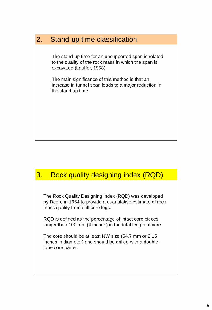
EXAMPLES OF ROCKBOLT
5. Rock Mass Rating System (RMR)
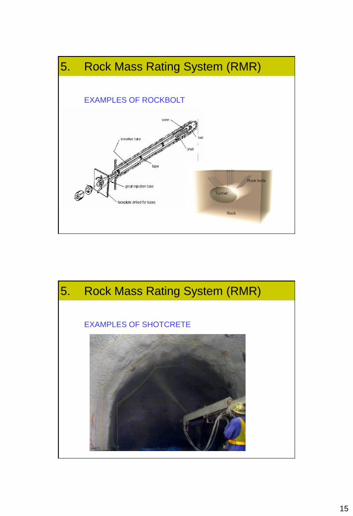
EXAMPLES OF SHOTCRETE
5. Rock Mass Rating System (RMR)

16
5. Rock Mass Rating System (RMR)
PRACTICAL EXAMPLE
A tunnel is to be driven through a slightly weathered
granite with a dominant joint set dipping at 60o against
the direction of the drive. Index testing and logging of
diamond drilled core give typical Point- load strength
index values of 8 MPa and average RQD values of 70%.
The slightly rough and slightly weathered joints with a
separation of < 1 mm, are spaced at 300 mm. Tunneling
conditions are anticipated to be wet.
5. Rock Mass Rating System (RMR)
The RMR value is determined as follows:
Table Item Value Rating
A.1 Point load index 8 MPa 12
A.2 RQD 70% 13
A.3 Spacing of discontinuities 300 mm 10
E.4 Condition of discontinuities Note 1 22
A.5 Groundwater Wet 7
B Adjustment for joint orientation Note 2 -5
Total 59
Note 1: For slightly rough and altered discontinuity surfaces with a separation of < 1 mm, Table A.4
gives a rating of 25. When more detailed information is available, Table E can be used to obtain a
more refined rating. Hence, in this case, the rating is the sum of: 4 (1-3 m discontinuity length), 4
(separation 0.1-1.0 mm), 3 (slightly rough), 6 (no infilling) and 5 (slightly weathered) = 22.
Note 2: Table 4.4.F gives a description of ‘Fair’ for the conditions assumed where the tunnel is to be
driven against the dip of a set joints dipping at 60o. Using this description for ‘Tunnel and Mines’ in
Table 4.4.B gives an adjustment rating of –5.
SOLUTION

17
• Note 1: For slightly rough and altered discontinuity surfaces with a separation of < 1 mm, Table A.4 gives a rating of 25. When more detailed information is available, Table E can be used to obtain a more refined rating. Hence, in this case, the rating is the sum of: 4 (1-3 m discontinuity length), 4 (separation 0.1-1.0 mm), 3 (slightly rough), 6 (no infilling) and 5 (slightly weathered) = 22.
• Note 2: Table 4.4.F gives a description of ‘Fair’ for the conditions assumed where the tunnel is to be driven against the dip of a set joints dipping at 60o. Using this description for ‘Tunnel and Mines’ in Table 4.4.B gives an adjustment rating of –5.
Rock mass class Excavation Rock bolts
(20 mm diameter, fully
grouted)
Shotcrete Steel sets
I – Very good rock
RMR: 81 –100
Full face,
3 m advance.
Generally no support required except spot bolting.
II – Good rock
RMR: 61 - 80
Full face,
1 – 1.5 m advance. Complete
support 20 m from face.
Locally, bolts in crown
3 m long, spaced 2.5 m
with occasional wire mesh.
50 mm in crown
where required.
None.
III – Fair rock
RMR: 41 - 60
Top heading and bench
1.5 – 3 m advance in top heading.
Commerce support after each blast.
Complete support 10 m from face.
Systematic bolts 4 m long
spaced 1.5 – 2 m in crown
and walls with wire mesh
in crown.
50 – 100 mm in
crown and 30 mm
in sides.
None
5. Rock Mass Rating System (RMR)
With RMR = 59, Table suggests that
a tunnel could be excavated by top
heading and bench, with a 1.5 to 3 m
advance in the top heading. Support
should be installed after each blast
and the support should be placed at
a maximum distance of 10 m from
the face.
Systematic rock bolting, using 4 m long
20 mm diameter fully grouted bolts
spaced at 1.5 to 2 m in the crown and
walls, is recommended. Wire mesh, with
50 to 100 mm of shotcrete for the crown
and 30 mm of shotcrete for the walls, is
recommended.

18
The Q-system of rock mass classification was developed in Norway in 1974 by Nick Barton, Lien, R., and Lunde, J at NGI (Norwegian Geotechnical Institute).
The system was developed on the basis of an analysis of 212 tunnel case histories from Scandinavia. It is a quantitative classification system and is an engineering system facilitating the design of tunnel supports
6. Rock Tunneling Quality Index, Q
6. Rock Tunneling Quality Index, Q

19
CLASSIFICATION OF INDIVIDUAL PARAMETERS
6. Rock Tunneling Quality Index, Q
Jr
CLASSIFICATION OF INDIVIDUAL PARAMETERS
Jr
6. Rock Tunneling Quality Index, Q

20
CLASSIFICATION OF INDIVIDUAL PARAMETERS
6. Rock Tunneling Quality Index, Q
Jw
CLASSIFICATION OF INDIVIDUAL PARAMETERS
6. Rock Tunneling Quality Index, Q

21
Equivalent Dimension, De
6. Rock Tunneling Quality Index, Q

22
6. Rock Tunneling Quality Index, Q
ESTIMATED SUPPORT CATEGORIES
6. Rock Tunneling Quality Index, Q

23
PRACTICAL EXAMPLE
A 15 m span crusher chamber for an underground mine is to be
excavated in a norite at depth of 2,100 m below surface. The rock
mass contains two sets of joints controlling stability. These joints
are undulating, rough and unweathered with very minor surface
staining. RQD values range from 85% to 95% and laboratory tests
on core samples of intact rock give an average uniaxial
compressive strength of 170 MPa. The principal stress directions
are approximately vertical and horizontal and the magnitude of the
horizontal principal stress is approximately 1.5 times that of the
vertical principal stress. The rock mass is locally damp but there is
no evidence of flowing water.
6. Rock Tunneling Quality Index, Q
Parameter Description Value
RQD 85% to 95% 90 (average)
Jn for two joint sets 4
Jr rough or irregular which are undulating 3
Ja unaltered joint wall with surface staining only 1
Jw excavation with minor inflow 1
SRF σc /σ1 < 2.5 (competent rock) 15 (average)
6. Rock Tunneling Quality Index, Q
For a depth below surface of 2,100 m the
overburden stress will be approximately 57 MPa
(2100 m2 x 27kN/m3 = 57 MPa)
1.5 x 57 = 85 MPa (the major principal stress
σ1)
Given, the uniaxial compressive strength of the
norite is approximately 170 MPa, this gives a
ratio of σc /σ1 = 2.
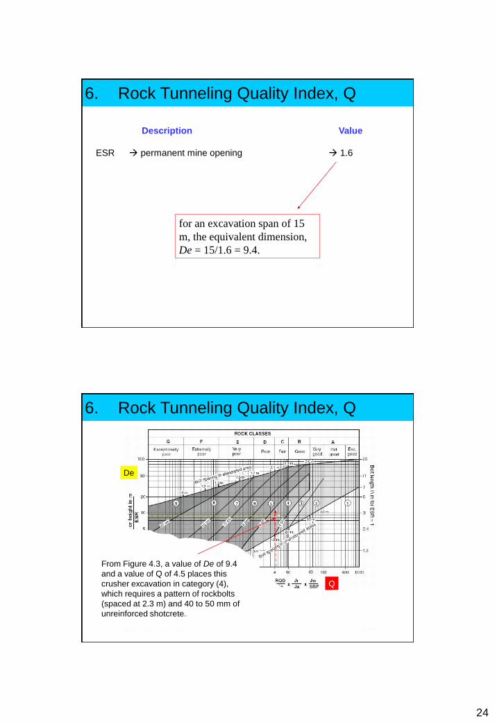
24
Description Value
ESR permanent mine opening 1.6
for an excavation span of 15
m, the equivalent dimension,
De = 15/1.6 = 9.4.
6. Rock Tunneling Quality Index, Q
De
Q
6. Rock Tunneling Quality Index, Q
From Figure 4.3, a value of De of 9.4
and a value of Q of 4.5 places this
crusher excavation in category (4),
which requires a pattern of rockbolts
(spaced at 2.3 m) and 40 to 50 mm of
unreinforced shotcrete.

25
6. Rock Tunneling Quality Index, Q
Length of rockbolt,
Permanent roof support
pressure,
ADDITIONAL (Barton et al, 1980)
Bieniawski suggested that a classification for jointed
rock mass should:
• divide the rock mass into groups of similar
behaviour;
• provide a good basis for understanding the
characteristics of the rock mass;
• facilitate the planning and the design of
structures
in rock by yielding quantitative data required for
the solution of real engineering problems; and
• provide a common basis for effective
communication among all persons concerned with
a geomechanics problem.
7. CSIR Classification for jointed rock

26
7. CSIR Classification for jointed rock
These aims should be fulfilled by ensuring that
the adopted classification is
• simple and meaningful in term; and
• based on measurable parameters which can
be determined quickly and cheaply in the field.
In order to satisfy these requirements, Bieniawski
originally proposed that his “Geomechanics
Classification” should incorporate the following
parameters:
• Rock Quality Designation (RQD),
• State of weathering,
• Uniaxial compressive strength of intact rock,
• Spacing of joints and bedding,
• Strike and dip orientations,
• Separation of joints,
• Continuity of joints, and
• Ground water inflow.
7. CSIR Classification for jointed rock

27
The five classification parameters then became:
• Strength of intact rock material table 3
• Rock Quality Designation
• Spacing of joints table 4
• Condition of joints
• Ground water conditions
7. CSIR Classification for jointed rock
Table 3 – DEERE AND MILLER‟S CLASSIFICATION OF INTACT ROCK STRENGTH
DescriptionUniaxial Compressive Strength
Example of rock typesLbf/in2 kgf/cm2 MPa
Very low strength
Low strength
Medium strength
High strength
Very high strength
150 – 3500
3500 – 7500
7500 – 15000
15000 –
30000
> 30000
10 – 250
250 – 500
500 – 1000
1000 –
2000
> 2000
1 – 25
25 – 50
50 – 100
100 – 200
> 200
Chalk, rocksalt.
Coal, siltstone, schist.
Sandstone, slate, shale.
Marble, granite, gneiss.
Quartzite, dolerite, gabbro, basalt
Table 4 – DEERE‟S CLASSIFICATION FOR JOINT SPACING
Description Spacing of joints Rock mass grading
Very wide
Wide
Moderately close
Close
Very close
> 3 m
1 m to 3 m
0.3 m to 1 m
50 mm to 300 mm
< 50 mm
> 10 ft
3 ft to 10 ft
1 ft to 3 ft
2 in to 1 ft
< 2 in
Solid
Massive
Blocky/seamy
Fractured
Crushed and shattered
7. CSIR Classification for jointed rock

28
PARAMETER RANGES OF VALUES
1. Strength of intact
rock material
Point
load
strength
> 8 MPa 4 – 8 MPa 2 – 4 MPa 1 – 2 MPa
For this low range uniaxial
compressive test is preferred
Uniaxial
compressi
ve
strength
> 250 MPa 100 – 250 MPa 50 – 100 MPa 25 -50 MPa
10 –
25
MPa
3 – 10
MPa
1 – 3
MPa
Rating 15 12 7 4 2 1 0
2. Drill core quality RQD 90% - 100% 75% - 90% 50% - 75% 25% - 50% < 25%
Rating 20 17 13 8 3
3. Spacing of joints > 3 m 1 – 3 m 0.3 – 1 m 50 – 300 mm < 50 mm
Rating 30 25 20 10 5
4. Condition of joints Very rough
surfaces
Not continuous
No separation
Hard joint wall
rock
Slightly rough
surfaces
Separation < 1 mm
Hard joint wall
rock
Slightly rough
surfaces
Separation < 1 mm
Soft joint wall
rock
Slickensided
surfaces or
Gough < 5 mm
thick or
Joint open 1 – 5
mm
Continuous joints
Soft gouge > 5 mm thick or
Joints open > 5 mm
Continuous joints
Rating 25 20 12 6 0
5 Ground water Inflow per 10
m tunnel
length
None
Or
0
Or
Completely dry
< 25 litres/ min
Or
0.0 – 0.2
Or
Moist only
(interstitial water)
25 – 125 litres/
min
Or
0.2 – 0.5
Or
Water under
moderate pressure
> 125 litres/ min
Or
> 0.5
Or
Severe water problemsRatio:
Joint water
pressure/
major
principal
stress
General
conditions
Rating 10 7 4 0
A. CLASSIFICATION PARAMETERS AND THEIR RATINGS
7. CSIR Classification for jointed rockTa
ble
5
B. RATING ADJUSTMENT FOR JOINT ORIENTATIONS
Strike and dip
orientations of joints
Very favourable Favourable Fair Unfavourable Very unfavourable
Rating Tunnel 0 -2 -5 -10 -12
Foundati
ons
0 -2 -7 -15 -25
Slopes 0 -5 -25 -50 -60
C. ROCK MASS CLASSES DETERMINED FROM TOTAL RATINGS
Rating 100 – 81 80 – 61 60 – 41 40 – 21 < 20
Class no. I II III IV V
Description Very good rock Good rock Fair rock Poor rock Very poor rock
D. MEANING OF ROCK MASS CLASSES
Class no. I II III IV V
Average stand –up time 10 years for 5 m span 6 months for 4 m span 1 week for 3 m span 5 hours for 1.5 m span 10 min for 0.5 m span
Cohesion of the rock
mass
> 300 kPa 200 – 300 kPa 150 – 200 kPa 100 – 150 kPa < 100 kPa
Friction angle of the
rock mass
> 45o 40o – 45o 35o – 40o 30o – 35o < 30o
7. CSIR Classification for jointed rock
Ta
ble
5

29
Strike perpendicular to tunnel axis Strike parallel to tunnel axis Dip 0o – 20o
irrespective of
strikeDrive with dip Drive against dip
Dip 45o – 90o Dip 20o – 45o Dip 45o – 90o Dip 20o – 45o Dip 45o – 90o Dip 20o – 45o
Very favourable Favourable Fair Unfavourable Very
unfavourable
Fair Unfavourable
TABLE 6 – THE EFFECT OF JOINT STRIKE AND DIP ORIENTATIONS IN
TUNNELING
7. CSIR Classification for jointed rock
PRACTICAL EXAMPLE
Consider the example of a granitic rock mass in which a tunnel is to be driven.
The classification has been carried out as follows:
7. CSIR Classification for jointed rock

30
The tunnel has been oriented such that the dominant joint set strikes
perpendicular to the tunnel axis with a dip of 30o against the drive
direction. From Table 6,
this situation is described as unfavourable for which a rating
adjustment of –10 is obtained from Table 5B.
Thus the final rock mass rating becomes 59 which places the rock
mass at the upper end of Class III with a description of fair.
Figure 6 gives the stand-up time of an unsupported 3 metre tunnel
in this rock mass as approximately 1 month.
7. CSIR Classification for jointed rock
PRACTICAL EXAMPLE
Figure 6: relationship between the stand-up time of an unsupported
underground excavation span and the CSIR Geomechanics
Classification proposed by Bieniawski
7. CSIR Classification for jointed rock

31
http://www.geoconsol.com/page
s.php?page=a
Figure 7. Relationship between the maximum equivalent dimension
De of an unsupported underground excavation and the NGI tunneling
quality index Q. (After Barton, Lien and Lunde1).
7. CSIR Classification for jointed rock