Embed Size (px)
Citation preview
Rockwell Automation 1606-XLE80E 24V, 3.3A; Single Phase Input
10000108328 (Version 00)
www.ra.rockwell.com
Page 1
1606-XLE80E 24V,3.3A Single Phase Input
POWER SUPPLY Ultra-small size Extra-low inrush current Active power factor correction Wide range AC/DC input Superior efficiency and temperature rating DC-OK
1. GENERAL DESCRIPTION The 1606 XLE power suppliesare cost optimized power supplies without compromising quality, reliability and performance. The 1606-XLE80E is part of the XLE power supply family.
The 1606-XLE includes all the essential basic functions. The most important features are the small size, the high efficiency and the wide temperature range.The wide-range-input makes worldwide installation and usage very simple.
2. SPECIFICATION QUICK REFERENCE Output voltage DC 24V Adjustment range 24 - 28V Output current 3.3A At 24Vdc 2.7A At 28Vdc Output power 80W Output ripple < 50mVpp 20Hz to 20MHz Input voltage AC 100-240V Wide-range Input Line frequency 50-60Hz ±6% AC Input current typ. 1.24 / 0.68A At 120 / 230Vac Power factor typ. 0.61 / 0.56 At 120 / 230Vac AC Inrush current typ. 23 / 45A At 120 / 230Vac DC Input 110-375Vdc Full output current 88-110Vdc Output current max.
2.5A Efficiency typ. 88.0 / 89.8% At 120 / 230Vac Losses typ. 11.1 / 9.1W At 120 / 230Vac Temperature range -25°C to +70°C Operational Derating 1.8W/°C +60 to +70°C Hold-up time typ. 29 / 120ms At 120 / 230Vac Dimensions 32x124x102mm WxHxD
3. AGENCY APPROVALS
IND. CONT. EQ. UL 508
UL 60950-1
EMC, LVD
4. RELATED PRODUCTS 1606-XLB Wall mount bracket 1606-XLSRED Redundancy Module 1606-XLBUFFER Buffer unit
Rockwell Automation 1606-XLE80E 24V, 3.3A; Single Phase Input
10000108328 (Version 00)
www.ra.rockwell.com
Page 2
INDEX PAGE INDEX PAGE 1. General Description................................................................1 2. Specification Quick reference.................................................1 3. Agency Approvals...................................................................1 4. Related Products ....................................................................1 5. AC-Input..................................................................................3 6. DC-Input .................................................................................4 7. Input Inrush Current Surge .....................................................5 8. Hold-up Time ..........................................................................5 9. Output .....................................................................................6 10. Efficiency and Power Losses..................................................7 11. Functional Diagram ................................................................8 12. Reliability ................................................................................8 13. Product Face Label ................................................................9 14. Terminals and Wiring............................................................10 15. EMC......................................................................................11 16. Environment .........................................................................12 17. Protection Features ..............................................................12 18. Safety....................................................................................13 19. Dielectric Strength ................................................................13 20. Approvals..............................................................................14
21. Fulfilled Standards ................................................................14 22. Used Substances..................................................................15 23. Physical Dimensions and Weight .........................................15 24. Installation and Operation Instructions .................................16 25. Accessory .............................................................................16 26. Application Notes ..................................................................17
26.1. Peak Current Capability ...........................................17 26.2. Charging of Batteries................................................17 26.3. Back-feeding Loads..................................................17 26.4. Output Circuit Breakers ............................................18 26.5. Inductive and Capacitive Loads ...............................18 26.6. Series Operation ......................................................19 26.7. Parallel Use to Increase Output Power ....................19 26.8. Parallel Use for 1+1 Redundancy ............................19 26.9. External Input Protection ..........................................19 26.10. Operation on Two Phases........................................20 26.11. Use in a Tightly Sealed Enclosure ...........................20 26.12. Mounting Orientations ..............................................21
INTENDED USE Those responsible for the application and use of the products must satisfy themselves that all necessary steps have been taken to assure that each application and use meets all performance and safety requirements, including and applicable laws, regulation , codes, and standards.
TERMINOLOGY AND ABREVIATIONS PE and symbol PE is the abbreviation for Protective Earth and has the same meaning as the symbol . Earth, Ground This document uses the term “earth” which is the same as the U.S. term “ground”. T.b.d. To be defined, value or description will follow later. AC 230V A figure displayed with the AC or DC before the value represents a nominal voltage with standard tolerances (usually
±20%) included. E.g.: DC 12V describes a 12V battery disregarding whether it is charged (13.7V) or discharged (10V). As long as not otherwise stated, AC 100V and AC 230V parameters are valid at 50Hz and AC 120V parameters are valid at 60Hz mains frequency.
230Vac A figure with the unit (Vac) at the end is a momentary figure without any additional tolerances included. 50Hz vs. 60Hz As long as not otherwise stated, AC 380V and AC 400V parameters are valid at 50Hz and AC 480V
parameters are valid at 60Hz mains frequency. PELV Protective Extra Low Voltage SELV Safety Extra Low Voltage
Rockwell Automation 1606-XLE80E-2 24V, 3.3A; Single Phase Input
10000108328 (Version 00)
www.ra.rockwell.com Page 3
5. AC-INPUT
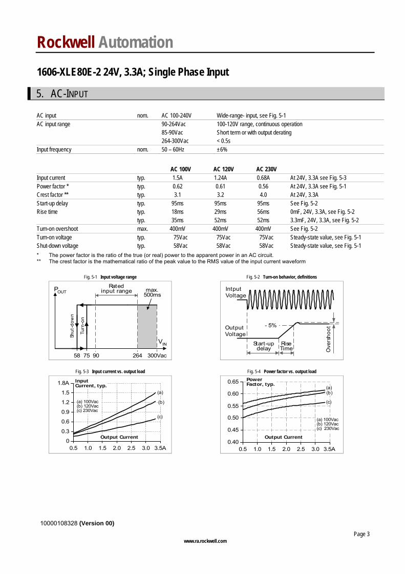
AC input nom. AC 100-240V Wide-range- input, see Fig. 5-1 AC input range 90-264Vac 100-120V range, continuous operation 85-90Vac Short term or with output derating 264-300Vac < 0.5s Input frequency nom. 50 – 60Hz ±6%
AC 100V AC 120V AC 230V
Input current typ. 1.5A 1.24A 0.68A At 24V, 3.3A see Fig. 5-3 Power factor * typ. 0.62 0.61 0.56 At 24V, 3.3A see Fig. 5-1 Crest factor ** typ. 3.1 3.2 4.0 At 24V, 3.3A Start-up delay typ. 95ms 95ms 95ms See Fig. 5-2 Rise time typ. 18ms 29ms 56ms 0mF, 24V, 3.3A, see Fig. 5-2 typ. 35ms 52ms 52ms 3.3mF, 24V, 3.3A, see Fig. 5-2 Turn-on overshoot max. 400mV 400mV 400mV See Fig. 5-2 Turn-on voltage typ. 75Vac 75Vac 75Vac Steady-state value, see Fig. 5-1 Shut-down voltage typ. 58Vac 58Vac 58Vac Steady-state value, see Fig. 5-1
* The power factor is the ratio of the true (or real) power to the apparent power in an AC circuit. ** The crest factor is the mathematical ratio of the peak value to the RMS value of the input current waveform
Fig. 5-1 Input voltage range Fig. 5-2 Turn-on behavior, definitions
Turn
-on
90
Ratedinput range max.
500ms
VIN
POUT
58 300Vac264
Shut
-dow
n
75
Start-updelay
RiseTime O
vers
hoot
- 5%OutputVoltage
IntputVoltage
Fig. 5-3 Input current vs. output load Fig. 5-4 Power factor vs. output load
0.5 1.51.0 2.0 2.5 3.0 3.5A0
0.3
0.6
0.9
1.2
1.5
1.8A
Output Current
InputCurrent, typ.
(a) 100Vac(b) 120Vac(c) 230Vac
(a)
(b)
(c)
PowerFactor, typ.
0.5 1.0 1.5 2.0 3.5A0.40
0.45
0.50
0.55
0.60
0.65
Output Current
2.5 3.0
(a) 100Vac(b) 120Vac(c) 230Vac
(a)(b)
(c)
Rockwell Automation 1606-XLE80E-2 24V, 3.3A; Single Phase Input
10000108328 (Version 00)
www.ra.rockwell.com Page 4
6. DC-INPUT
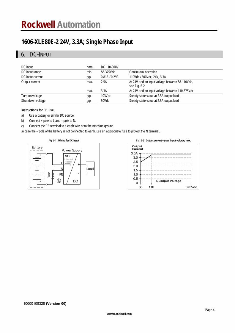
DC input nom. DC 110-300V DC input range min. 88-375Vdc Continuous operation DC input current typ. 0.81A / 0.29A 110Vdc / 300Vdc, 24V, 3.3A
Output current max. 2.5A At 24V and an input voltage between 88-110Vdc, see Fig. 6-2
max. 3.3A At 24V and an input voltage between 110-375Vdc Turn-on voltage typ. 103Vdc Steady-state value at 2.5A output load Shut-down voltage typ. 50Vdc Steady-state value at 2.5A output load
Instructions for DC use: a) Use a battery or similar DC source. b) Connect + pole to L and – pole to N. c) Connect the PE terminal to a earth wire or to the machine ground. In case the – pole of the battery is not connected to earth, use an appropriate fuse to protect the N terminal.
Fig. 6-1 Wiring for DC input Fig. 6-2 Output current versus input voltage, max.
Fuse
+
-
Load
L
N
PE
+
-
Power Supply
AC
DC
Battery
internalfused
0
1.51.0
2.0
0.5
3.5A
88 110 375Vdc
DC Input Voltage
2.53.0
OutputCurrent
Rockwell Automation 1606-XLE80E-2 24V, 3.3A; Single Phase Input
10000108328 (Version 00)
www.ra.rockwell.com Page 5
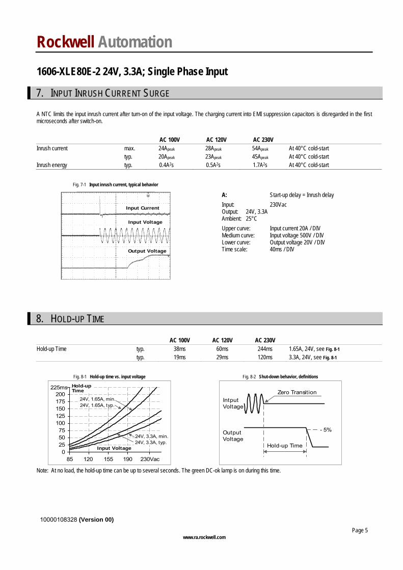
7. INPUT INRUSH CURRENT SURGE A NTC limits the input inrush current after turn-on of the input voltage. The charging current into EMI suppression capacitors is disregarded in the first microseconds after switch-on. AC 100V AC 120V AC 230V
Inrush current max. 24Apeak 28Apeak 54Apeak At 40°C cold-start typ. 20Apeak 23Apeak 45Apeak At 40°C cold-start Inrush energy typ. 0.4A2s 0.5A2s 1.7A2s At 40°C cold-start
Fig. 7-1 Input inrush current, typical behavior
Input Current
Input Voltage
Output Voltage
A: Start-up delay = Inrush delay Input: 230Vac Output: 24V, 3.3A Ambient: 25°C Upper curve: Input current 20A / DIV Medium curve: Input voltage 500V / DIV Lower curve: Output voltage 20V / DIV Time scale: 40ms / DIV
8. HOLD-UP TIME
AC 100V AC 120V AC 230V Hold-up Time typ. 38ms 60ms 244ms 1.65A, 24V, see Fig. 8-1 typ. 19ms 29ms 120ms 3.3A, 24V, see Fig. 8-1
Fig. 8-1 Hold-up time vs. input voltage Fig. 8-2 Shut-down behavior, definitions
0255075
100
225ms
85 120 155 190 230Vac
Input Voltage
125150175
Hold-upTime
200
24V, 3.3A, min.24V, 3.3A, typ.
24V, 1.65A, min.24V, 1.65A, typ.
- 5%
Hold-up Time
Zero Transition
OutputVoltage
IntputVoltage
Note: At no load, the hold-up time can be up to several seconds. The green DC-ok lamp is on during this time.
Rockwell Automation 1606-XLE80E-2 24V, 3.3A; Single Phase Input
10000108328 (Version 00)
www.ra.rockwell.com Page 6
9. OUTPUT
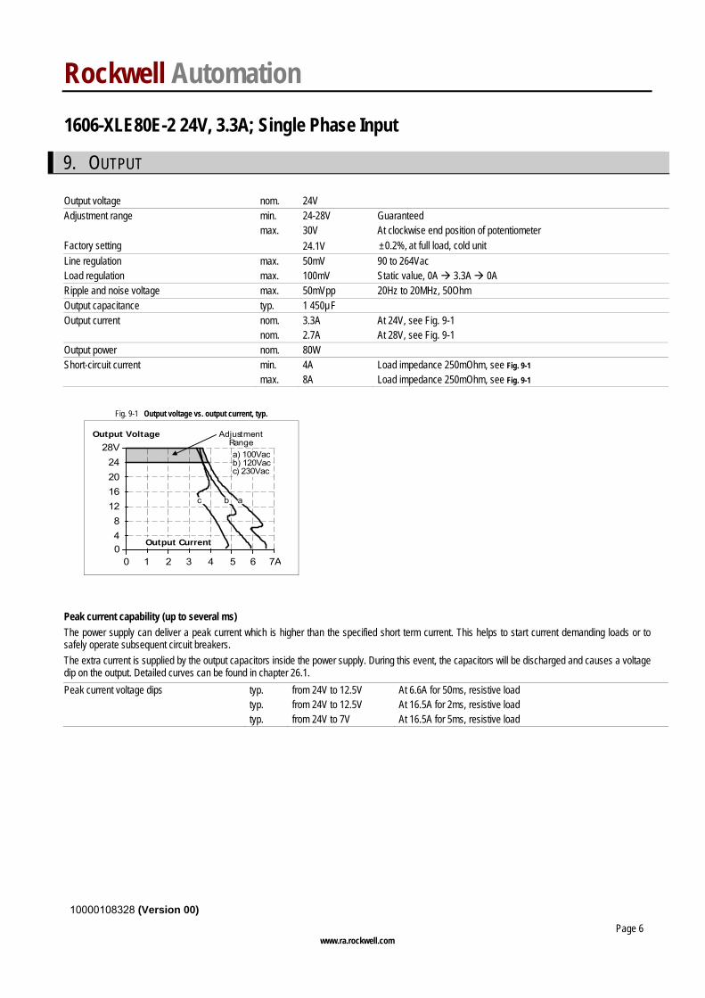
Output voltage nom. 24V Adjustment range min. 24-28V Guaranteed max. 30V At clockwise end position of potentiometer Factory setting 24.1V ±0.2%, at full load, cold unit Line regulation max. 50mV 90 to 264Vac Load regulation max. 100mV Static value, 0A 3.3A 0A Ripple and noise voltage max. 50mVpp 20Hz to 20MHz, 50Ohm Output capacitance typ. 1 450µF Output current nom. 3.3A At 24V, see Fig. 9-1 nom. 2.7A At 28V, see Fig. 9-1 Output power nom. 80W Short-circuit current min. 4A Load impedance 250mOhm, see Fig. 9-1 max. 8A Load impedance 250mOhm, see Fig. 9-1
Fig. 9-1 Output voltage vs. output current, typ.
Output Voltage
00 4
48
12
28V
162024
7A621 3 5
AdjustmentRange
Output Current
a) 100Vacb) 120Vacc) 230Vac
abc
Peak current capability (up to several ms) The power supply can deliver a peak current which is higher than the specified short term current. This helps to start current demanding loads or to safely operate subsequent circuit breakers. The extra current is supplied by the output capacitors inside the power supply. During this event, the capacitors will be discharged and causes a voltage dip on the output. Detailed curves can be found in chapter 26.1.
Peak current voltage dips typ. from 24V to 12.5V At 6.6A for 50ms, resistive load typ. from 24V to 12.5V At 16.5A for 2ms, resistive load typ. from 24V to 7V At 16.5A for 5ms, resistive load
Rockwell Automation 1606-XLE80E-2 24V, 3.3A; Single Phase Input
10000108328 (Version 00)
www.ra.rockwell.com Page 7
10. EFFICIENCY AND POWER LOSSES
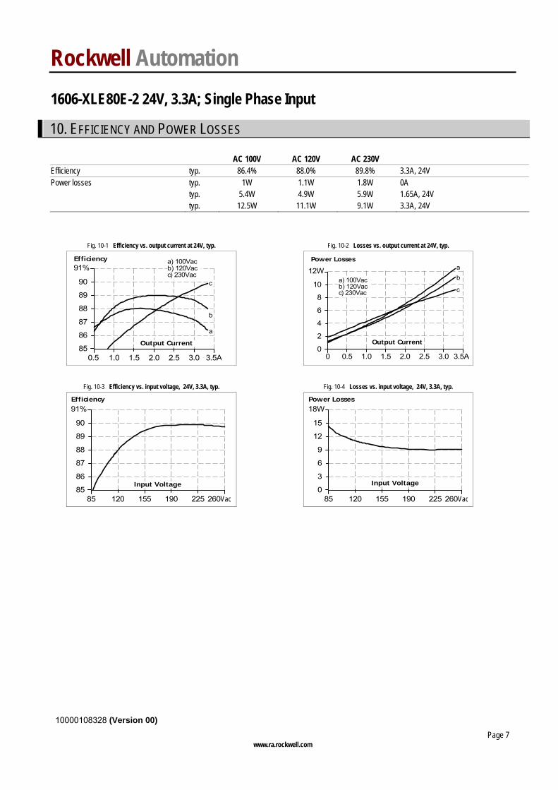
AC 100V AC 120V AC 230V Efficiency typ. 86.4% 88.0% 89.8% 3.3A, 24V Power losses typ. 1W 1.1W 1.8W 0A typ. 5.4W 4.9W 5.9W 1.65A, 24V typ. 12.5W 11.1W 9.1W 3.3A, 24V
Fig. 10-1 Efficiency vs. output current at 24V, typ. Fig. 10-2 Losses vs. output current at 24V, typ.
Efficiency
0.5 1.0 3.5A
86
87
88
89
Output Current
90
91%
852.0 3.01.5 2.5
a) 100Vacb) 120Vacc) 230Vac
a
b
c
Power Losses
0 0.5 3.5A0
2
4
6
8
10
12W
1.0 1.5 2.0 2.5 3.0
Output Current
a) 100Vacb) 120Vacc) 230Vac
ab
c
Fig. 10-3 Efficiency vs. input voltage, 24V, 3.3A, typ. Fig. 10-4 Losses vs. input voltage, 24V, 3.3A, typ.
Efficiency
85 120 155 190 225 260Vac85
86
87
88
Input Voltage
89
90
91%
Power Losses
0
3
6
9
12
15
18W
85 120 155 190 225 260Vac
Input Voltage
Rockwell Automation 1606-XLE80E-2 24V, 3.3A; Single Phase Input
10000108328 (Version 00)
www.ra.rockwell.com Page 8
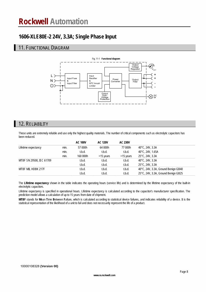
11. FUNCTIONAL DIAGRAM
Fig. 11-1 Functional diagram
++
--
VOUT
Input Fuse&Input Filter
OutputVoltage
Regulator
PowerConverter
OutputFilter
DCok
LN
OutputOver-
VoltageProtection
InputRectifier&NTC InrushLimiter
12. RELIABILITY These units are extremely reliable and use only the highest quality materials. The number of critical components such as electrolytic capacitors has been reduced.
AC 100V AC 120V AC 230V Lifetime expectancy min. 57 000h 64 000h 77 000h 40°C, 24V, 3.3A min. t.b.d. t.b.d. t.b.d. 40°C, 24V, 1.65A min. 160 000h >15 years >15 years 25°C, 24V, 3.3A MTBF SN 29500, IEC 61709 t.b.d. t.b.d. t.b.d. 40°C, 24V, 3.3A t.b.d. t.b.d. t.b.d. 25°C, 24V, 3.3A MTBF MIL HDBK 217F t.b.d. t.b.d. t.b.d. 40°C, 24V, 3.3A, Ground Benign GB40 t.b.d. t.b.d. t.b.d. 25°C, 24V, 3.3A, Ground Benign GB25
The Lifetime expectancy shown in the table indicates the operating hours (service life) and is determined by the lifetime expectancy of the built-in electrolytic capacitors. Lifetime expectancy is specified in operational hours. Lifetime expectancy is calculated according to the capacitor’s manufacturer specification. The prediction model allows a calculation of up to 15 years from date of shipment. MTBF stands for Mean Time Between Failure, which is calculated according to statistical device failures, and indicates reliability of a device. It is the statistical representation of the likelihood of a unit to fail and does not necessarily represent the life of a product.
Rockwell Automation 1606-XLE80E-2 24V, 3.3A; Single Phase Input
10000108328 (Version 00)
www.ra.rockwell.com Page 9
13. PRODUCT FACE LABEL
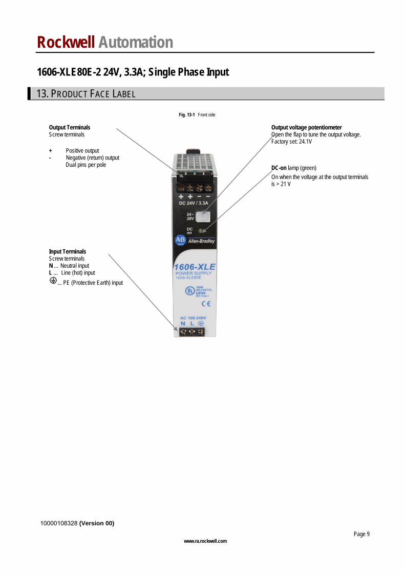
Fig. 13-1 Front side
Output voltage potentiometer Open the flap to tune the output voltage. Factory set: 24.1V
Output Terminals Screw terminals + Positive output - Negative (return) output Dual pins per pole
Input Terminals Screw terminals N … Neutral input L … Line (hot) input
... PE (Protective Earth) input
DC-on lamp (green) On when the voltage at the output terminals is > 21 V
Rockwell Automation 1606-XLE80E-2 24V, 3.3A; Single Phase Input
10000108328 (Version 00)
www.ra.rockwell.com Page 10
14. TERMINALS AND WIRING All terminals are easy to access when mounted on the panel. Input and output terminals are separated from each other (input below, output above) to help in error-free wiring.
Type Screw terminals Solid wire 0.5-6mm2 Stranded wire 0.5-4mm2 American wire gauge 20-10 AWG Ferrules Allowed, but not required Wire stripping length 7mm / 0.275inch Screwdriver 3.5mm slotted or Pozidrive No 2 Recommended tightening torque 0.8Nm, 7lb.in
Instructions: a) Use appropriate copper cables that are designed for an operating temperature of:
60°C for ambient up to 45°C and 75°C for ambient up to 60°C minimum. b) Follow national installation codes and installation regulations! c) Ensure that all strands of a stranded wire enter the terminal connection! d) Up to two stranded wires with the same cross section are permitted in one connection point (except PE wire). e) Do not use the unit without PE connection. f) In order to fulfill GL requirements, unused terminal spaces must be closed.
Rockwell Automation 1606-XLE80E-2 24V, 3.3A; Single Phase Input
10000108328 (Version 00)
www.ra.rockwell.com Page 11
15. EMC The CE mark is in conformance with EMC directive 89/336/EC, 93/68/EC and 2004/108/EC and the low-voltage directive (LVD) 73/23/EWG.
EMC Immunity EN 61000-6-2, EN 61000-6-1 Generic standards
Electrostatic discharge EN 61000-4-2 Contact discharge Air discharge
8kV 15kV
Criterion A Criterion A
Electromagnetic RF field EN 61000-4-3 80MHz-2.7GHz 10V/m Criterion A
Fast transients (Burst) EN 61000-4-4 Input lines Output lines
4kV 2kV
Criterion A Criterion A
Surge voltage on input EN 61000-4-5 L N N / L PE
2kV 4kV
Criterion A Criterion A
Surge voltage on output EN 61000-4-5 + - + / - PE
500V 500V
Criterion A Criterion A
Conducted disturbance EN 61000-4-6 0,15-80MHz 10V Criterion A
Mains voltage dips EN 61000-4-11 0% of 100Vac 40% of 100Vac 70% of 100Vac 0% of 200Vac 40% of 200Vac 70% of 200Vac
0Vac, 20ms 40Vac, 200ms 70Vac, 500ms 0Vac, 20ms 80Vac, 200ms 140Vac, 500ms
Criterion B *) Criterion C Criterion A Criterion A Criterion A Criterion A
Voltage interruptions EN 61000-4-11 0Vac, 5000ms Criterion C Input voltage swells RA internal standard 300Vac, 500ms Criterion A Powerful transients VDE 0160 Over entire load range 750V, 1.3ms Criterion A
Criterions: A: Power supply shows normal operation behavior within the defined limits. B: The power supply continuous to operate as intended after the test. No degradation of performance or loss of function occur, when the power supply is used as intended. During the test, degradation of performance is however possible. C: Temporary loss of function is possible. Power supply might shut-down and restarts by itself. No damages or hazards for the power supply will occur. *) Below 2.8A criterion A is fulfilled
EMC Emission EN 61000-6-3, EN 61000-6-4 Generic standards Conducted emission EN 55011, EN 55022, FCC Part 15, CISPR 11, CISPR 22 Class B, input lines EN 55022 Class A, output lines Radiated emission EN 55011, EN 55022 Class B Harmonic input current EN 61000-3-2 Fulfilled (Class A) Voltage fluctuations, flicker EN 61000-3-3 Fulfilled
This device complies with FCC Part 15 rules. Operation is subjected to following two conditions: (1) this device may not cause harmful interference, and (2) this device must accept any interference received, including interference that may cause undesired operation.
Switching frequency 50kHz to 450kHz Input voltage and load dependent
Rockwell Automation 1606-XLE80E-2 24V, 3.3A; Single Phase Input
10000108328 (Version 00)
www.ra.rockwell.com Page 12
16. ENVIRONMENT
Operational temperature -25°C to +70°C (-13°F to 158°F) Resistive load, Reduce output power according Fig. 16-1
Output de-rating 1.8W/°C 60-70°C (140°F to 158°F) Storage temperature -40 to +85°C (-40°F to 185°F) Storage and transportation
Humidity 5 to 95% r.H. IEC 60068-2-30 Do not energize while condensation is present
Vibration sinusoidal 2-17.8Hz: ±1.6mm; 17.8-500Hz: 2g 2 hours / axis
IEC 60068-2-6
Shock 30g 6ms, 20g 11ms 3 bumps / direction, 18 bumps in total
IEC 60068-2-27
Altitude 0 to 6000m (0 to 20 000ft) Reduce output power or ambient temperature above 2000m sea level.
Output de-rating (for altitude) 5W/1000m or 5°C/1000m above 2000m (6500ft), see Fig. 16-2 Over-voltage category III EN 50178, IEC 62103 altitudes < 2000m II Altitudes from 2000m to 6000m Degree of pollution 2 EN 50178, IEC 62103 not conductive
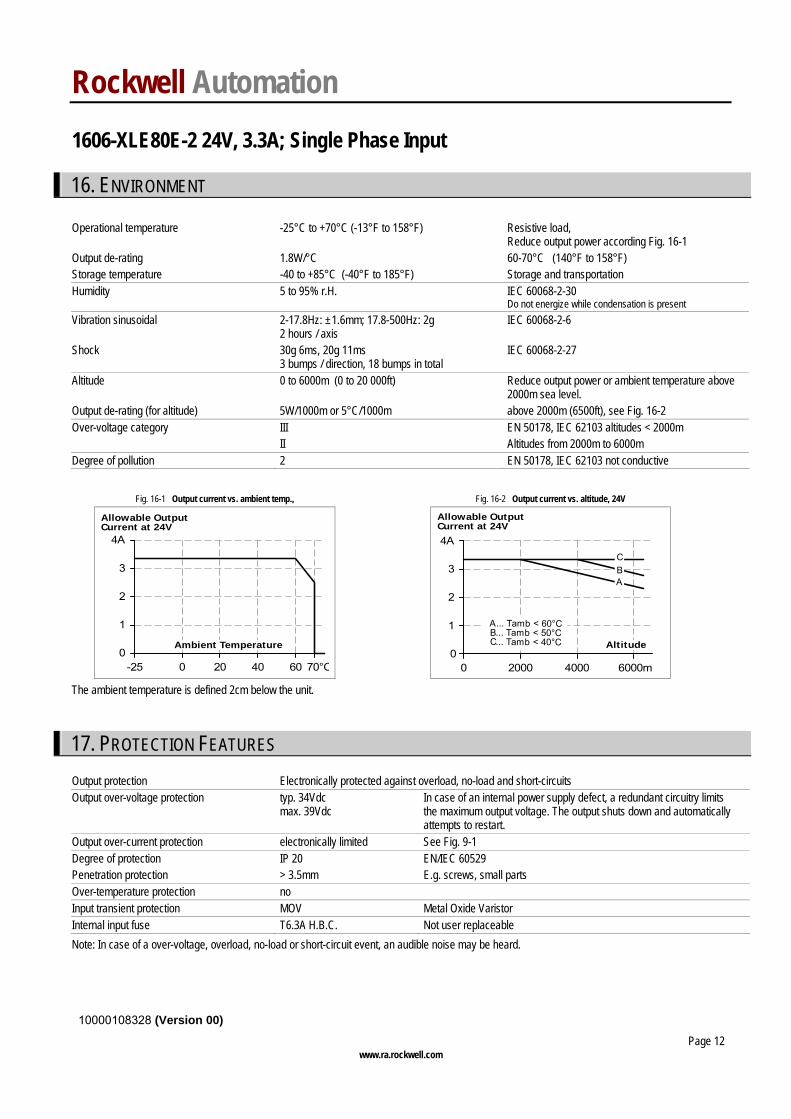
Fig. 16-1 Output current vs. ambient temp., Fig. 16-2 Output current vs. altitude, 24V
0-25 0 20 40 70°C
1
2
3
4A
60
Ambient Temperature
Allowable OutputCurrent at 24V
00 2000 4000 6000m
1
2
3
4A
Altitude
A... Tamb < 60°CB... Tamb < 50°CC... Tamb < 40°C
C
AB
Allowable OutputCurrent at 24V
The ambient temperature is defined 2cm below the unit.
17. PROTECTION FEATURES
Output protection Electronically protected against overload, no-load and short-circuits Output over-voltage protection typ. 34Vdc
max. 39Vdc In case of an internal power supply defect, a redundant circuitry limits the maximum output voltage. The output shuts down and automatically attempts to restart.
Output over-current protection electronically limited See Fig. 9-1 Degree of protection IP 20 EN/IEC 60529 Penetration protection > 3.5mm E.g. screws, small parts Over-temperature protection no Input transient protection MOV Metal Oxide Varistor Internal input fuse T6.3A H.B.C. Not user replaceable
Note: In case of a over-voltage, overload, no-load or short-circuit event, an audible noise may be heard.
Rockwell Automation 1606-XLE80E-2 24V, 3.3A; Single Phase Input
10000108328 (Version 00)
www.ra.rockwell.com Page 13
18. SAFETY
Input / output separation SELV IEC/EN 60950-1 PELV EN 60204-1, EN 50178, IEC 62103, IEC 60364-4-41 double or reinforced insulation Class of protection I PE (Protective Earth) connection required Isolation resistance > 5MOhm input to output, 500Vdc PE resistance < 0.1Ohm between housing and PE terminal Touch current (leakage current) typ. 0.16mA 100Vac, 50Hz typ. 0.24mA 120Vac, 60Hz typ. 0.41mA 230Vac, 50Hz < 0.22mA 110Vac, 50Hz < 0.32mA 132Vac, 60Hz < 0.57mA 264Vac, 50Hz
19. DIELECTRIC STRENGTH
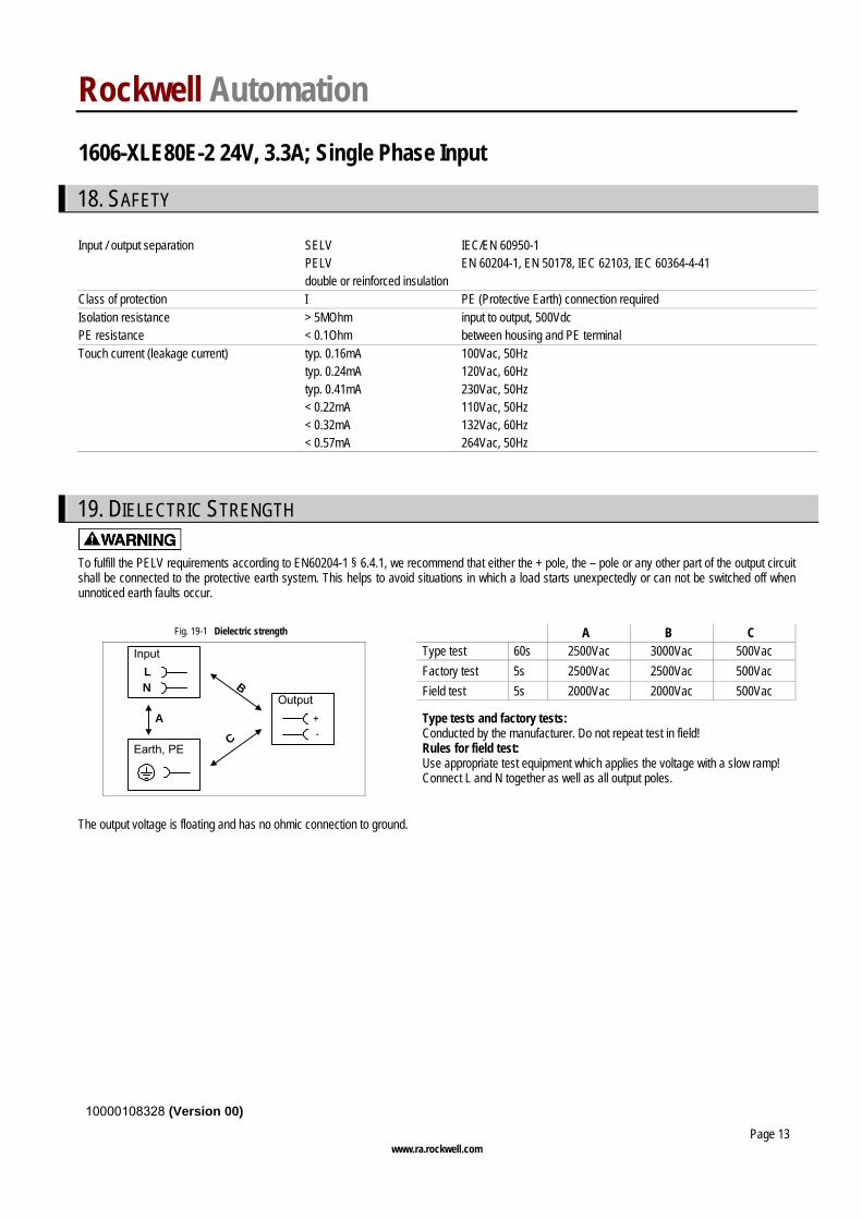
To fulfill the PELV requirements according to EN60204-1 § 6.4.1, we recommend that either the + pole, the – pole or any other part of the output circuit shall be connected to the protective earth system. This helps to avoid situations in which a load starts unexpectedly or can not be switched off when unnoticed earth faults occur.
Fig. 19-1 Dielectric strength A B C Type test 60s 2500Vac 3000Vac 500Vac Factory test 5s 2500Vac 2500Vac 500Vac Field test 5s 2000Vac 2000Vac 500Vac
A
C
NL
Input
Earth, PE
Output
-
+
B
Type tests and factory tests: Conducted by the manufacturer. Do not repeat test in field! Rules for field test: Use appropriate test equipment which applies the voltage with a slow ramp! Connect L and N together as well as all output poles.
The output voltage is floating and has no ohmic connection to ground.
Rockwell Automation 1606-XLE80E-2 24V, 3.3A; Single Phase Input
10000108328 (Version 00)
www.ra.rockwell.com Page 14
20. APPROVALS
IEC 60950-1 IECEE
CB SCHEME
CB Scheme, Information Technology Equipment
UL 508
IND. CONT. EQ.
18WMLISTED
LISTED E198865 Industrial Control Equipment
NEC Class 2 According to NEC (National Electrical Code) Article 725-41 (4). Listed as Limited Power Source (LPS) in the UL 60950-1 UL report.
UL 60950-1
RECOGNIZED E137006 recognized for the use in U.S.A. (UL 60950-1) and Canada (C22.2 No. 60950) Information Technology Equipment, Level 3
CSA pending R
182790C US
CSA approval for Canada CAN/CSA C22.2 No 107-1; CAN/ CSA 60950-1-03; UL60950-1
21. FULFILLED STANDARDS
EN 61558-2-17 Safety of Power Transformers EN/IEC 60204-1 Safety of Electrical Equipment of Machines EN/IEC 61131-2 Programmable Controllers EN 50178, IEC 62103 Electronic Equipment in Power Installations
Rockwell Automation 1606-XLE80E-2 24V, 3.3A; Single Phase Input
10000108328 (Version 00)
www.ra.rockwell.com Page 15
22. USED SUBSTANCES
The unit does not release any silicone and is suitable for the use in paint shops. The unit conforms to the RoHS directive 2002/96/EC Electrolytic capacitors included in this unit do not use electrolytes such as Quaternary Ammonium Salt Systems. Plastic housings and other molded plastic materials are free of halogens, wires and cables are not PVC insulated.
The production material within our production does not include following toxic chemicals: Polychlorized Biphenyl (PCB), Polychlorized Terphenyl (PCB), Pentachlorophenol (PCP), Polychlorinated naphthalene (PCN), Polybrom Biphenyl (PBB), Polybrom Bipheny-oxyd (PBO), Polybrominated Diphenylether (PBDE), Polychlorinated Diphenylether (PCDE), Polydibromphenyl Oxyd (PBDO), Cadmium, Asbest, Mercury, Silicia
23. PHYSICAL DIMENSIONS AND WEIGHT
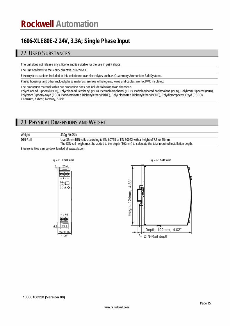
Weight 430g / 0.95lb DIN-Rail Use 35mm DIN-rails according to EN 60715 or EN 50022 with a height of 7.5 or 15mm.
The DIN-rail height must be added to the depth (102mm) to calculate the total required installation depth. Electronic files can be downloaded at www.ab.com
Fig. 23-1 Front view Fig. 23-2 Side view
Rockwell Automation 1606-XLE80E-2 24V, 3.3A; Single Phase Input
10000108328 (Version 00)
www.ra.rockwell.com Page 16
24. INSTALLATION AND OPERATION INSTRUCTIONS
Hazardous voltage inside device. Risk of electric shock, severe burns, or death.
• Do not use the unit without proper earth connection (Protective Earth). Use the pin on the terminal block for earth connection and not one of the screws on the housing.
• Turn power off before working on the power supply. Protect against inadvertent re-powering. • Make sure the wiring is correct by following all local and national codes. • Do not open, modify or repair the unit. • Use caution to prevent any foreign objects from entering into the housing. • Do not use in wet locations or in areas where moisture or condensation can be expected.
Mounting Orientation: Output terminal must be located on top and input terminal on the bottom. For other orientations see section 26.12 Cooling: Convection cooled, no forced cooling required. Do not cover ventilation grid (e.g. cable conduits) by more than 30%! Installation clearances: 40mm on top, 20mm on the bottom, 5mm on the left and right side are recommended when loaded permanently with full power. In case the adjacent device is a heat source, 15mm clearance is recommended. Service parts: The unit does not contain any serviceable parts. The tripping of an internal fuse is caused by an internal defect.
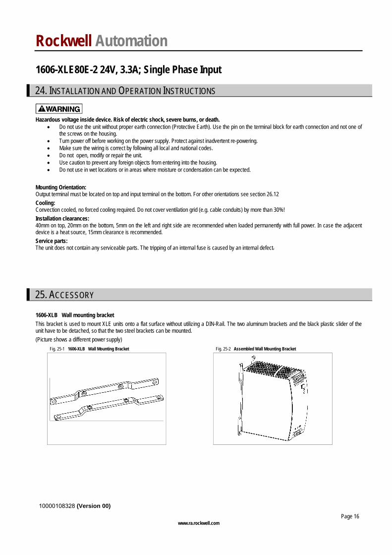
25. ACCESSORY 1606-XLB Wall mounting bracket This bracket is used to mount XLE units onto a flat surface without utilizing a DIN-Rail. The two aluminum brackets and the black plastic slider of the unit have to be detached, so that the two steel brackets can be mounted. (Picture shows a different power supply)
Fig. 25-1 1606-XLB Wall Mounting Bracket Fig. 25-2 Assembled Wall Mounting Bracket
Rockwell Automation 1606-XLE80E-2 24V, 3.3A; Single Phase Input
10000108328 (Version 00)
www.ra.rockwell.com Page 17
26. APPLICATION NOTES
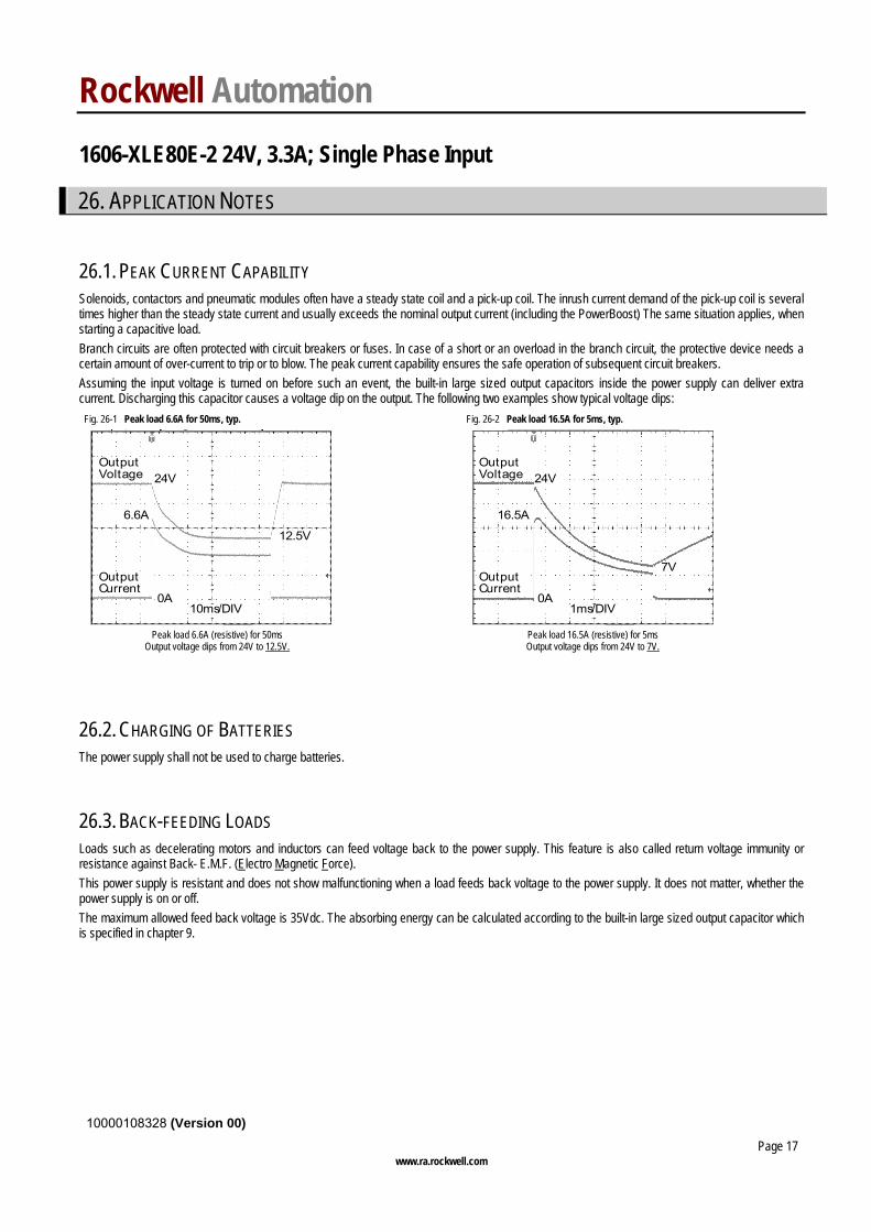
26.1. PEAK CURRENT CAPABILITY Solenoids, contactors and pneumatic modules often have a steady state coil and a pick-up coil. The inrush current demand of the pick-up coil is several times higher than the steady state current and usually exceeds the nominal output current (including the PowerBoost) The same situation applies, when starting a capacitive load. Branch circuits are often protected with circuit breakers or fuses. In case of a short or an overload in the branch circuit, the protective device needs a certain amount of over-current to trip or to blow. The peak current capability ensures the safe operation of subsequent circuit breakers. Assuming the input voltage is turned on before such an event, the built-in large sized output capacitors inside the power supply can deliver extra current. Discharging this capacitor causes a voltage dip on the output. The following two examples show typical voltage dips:
Fig. 26-1 Peak load 6.6A for 50ms, typ. Fig. 26-2 Peak load 16.5A for 5ms, typ.
10ms/DIV
OutputVoltage
OutputCurrent
24V
0A
6.6A
12.5V
1ms/DIV
OutputVoltage
OutputCurrent
24V
0A
16.5A
7V
Peak load 6.6A (resistive) for 50ms
Output voltage dips from 24V to 12.5V. Peak load 16.5A (resistive) for 5ms
Output voltage dips from 24V to 7V.
26.2. CHARGING OF BATTERIES The power supply shall not be used to charge batteries.
26.3. BACK-FEEDING LOADS Loads such as decelerating motors and inductors can feed voltage back to the power supply. This feature is also called return voltage immunity or resistance against Back- E.M.F. (Electro Magnetic Force). This power supply is resistant and does not show malfunctioning when a load feeds back voltage to the power supply. It does not matter, whether the power supply is on or off. The maximum allowed feed back voltage is 35Vdc. The absorbing energy can be calculated according to the built-in large sized output capacitor which is specified in chapter 9.
Rockwell Automation 1606-XLE80E-2 24V, 3.3A; Single Phase Input
10000108328 (Version 00)
www.ra.rockwell.com Page 18
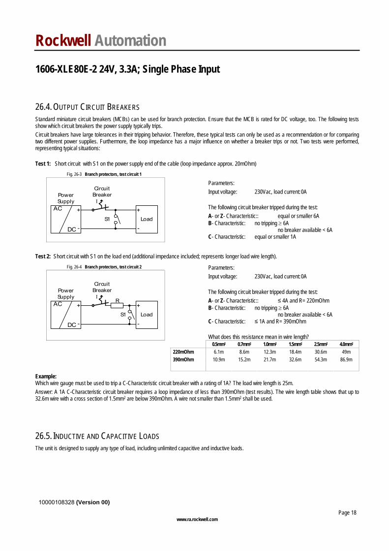
26.4. OUTPUT CIRCUIT BREAKERS Standard miniature circuit breakers (MCBs) can be used for branch protection. Ensure that the MCB is rated for DC voltage, too. The following tests show which circuit breakers the power supply typically trips. Circuit breakers have large tolerances in their tripping behavior. Therefore, these typical tests can only be used as a recommendation or for comparing two different power supplies. Furthermore, the loop impedance has a major influence on whether a breaker trips or not. Two tests were performed, representing typical situations: Test 1: Short circuit with S1 on the power supply end of the cable (loop impedance approx. 20mOhm)
Fig. 26-3 Branch protectors, test circuit 1
CircuitBreakerPower
SupplyAC
DC
+
-
I
Load+
-S1
Parameters: Input voltage: 230Vac, load current: 0A The following circuit breaker tripped during the test: A- or Z- Characteristic:: equal or smaller 6A B- Characteristic: no tripping ≥ 6A no breaker available < 6A C- Characteristic: equal or smaller 1A
Test 2: Short circuit with S1 on the load end (additional impedance included; represents longer load wire length).
Fig. 26-4 Branch protectors, test circuit 2
R
CircuitBreakerPower
SupplyAC
DC
+
-
I
S1 Load+
-
Parameters: Input voltage: 230Vac, load current: 0A The following circuit breaker tripped during the test: A- or Z- Characteristic:: ≤ 4A and R= 220mOhm B- Characteristic: no tripping ≥ 6A no breaker available < 6A C- Characteristic: ≤ 1A and R= 390mOhm What does this resistance mean in wire length?
0.5mm2 0.7mm2 1.0mm2 1.5mm2 2.5mm2 4.0mm2 220mOhm 6.1m 8.6m 12.3m 18.4m 30.6m 49m 390mOhm 10.9m 15.2m 21.7m 32.6m 54.3m 86.9m
Example: Which wire gauge must be used to trip a C-Characteristic circuit breaker with a rating of 1A? The load wire length is 25m. Answer: A 1A C-Characteristic circuit breaker requires a loop impedance of less than 390mOhm (test results). The wire length table shows that up to 32.6m wire with a cross section of 1.5mm2 are below 390mOhm. A wire not smaller than 1.5mm2 shall be used.
26.5. INDUCTIVE AND CAPACITIVE LOADS The unit is designed to supply any type of load, including unlimited capacitive and inductive loads.
Rockwell Automation 1606-XLE80E-2 24V, 3.3A; Single Phase Input
10000108328 (Version 00)
www.ra.rockwell.com Page 19
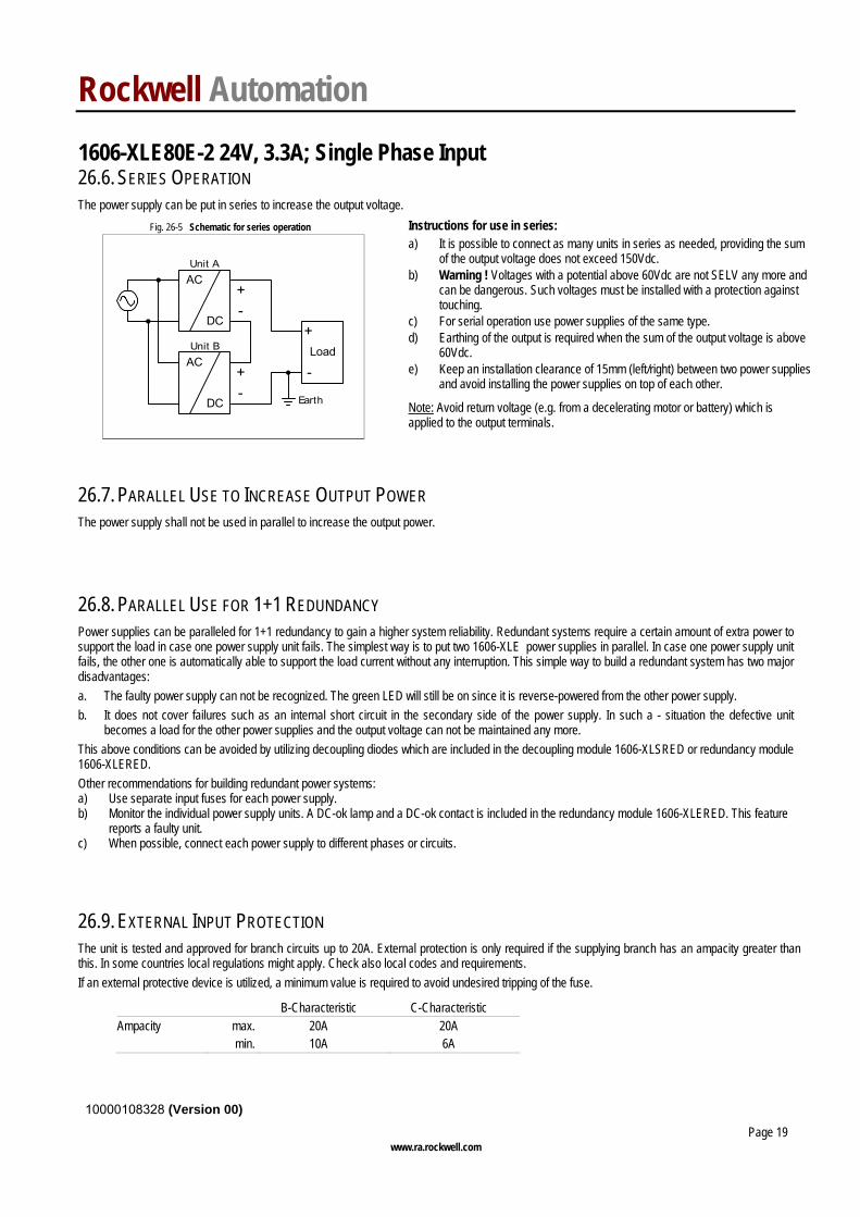
26.6. SERIES OPERATION The power supply can be put in series to increase the output voltage.
Fig. 26-5 Schematic for series operation Instructions for use in series:
Earth
Unit AAC
DC
Unit BAC
DC
-
+-
+
Load
+
-
a) It is possible to connect as many units in series as needed, providing the sum of the output voltage does not exceed 150Vdc.
b) Warning ! Voltages with a potential above 60Vdc are not SELV any more and can be dangerous. Such voltages must be installed with a protection against touching.
c) For serial operation use power supplies of the same type. d) Earthing of the output is required when the sum of the output voltage is above
60Vdc. e) Keep an installation clearance of 15mm (left/right) between two power supplies
and avoid installing the power supplies on top of each other.
Note: Avoid return voltage (e.g. from a decelerating motor or battery) which is applied to the output terminals.
26.7. PARALLEL USE TO INCREASE OUTPUT POWER The power supply shall not be used in parallel to increase the output power.
26.8. PARALLEL USE FOR 1+1 REDUNDANCY Power supplies can be paralleled for 1+1 redundancy to gain a higher system reliability. Redundant systems require a certain amount of extra power to support the load in case one power supply unit fails. The simplest way is to put two 1606-XLE power supplies in parallel. In case one power supply unit fails, the other one is automatically able to support the load current without any interruption. This simple way to build a redundant system has two major disadvantages: a. The faulty power supply can not be recognized. The green LED will still be on since it is reverse-powered from the other power supply. b. It does not cover failures such as an internal short circuit in the secondary side of the power supply. In such a - situation the defective unit
becomes a load for the other power supplies and the output voltage can not be maintained any more. This above conditions can be avoided by utilizing decoupling diodes which are included in the decoupling module 1606-XLSRED or redundancy module 1606-XLERED. Other recommendations for building redundant power systems: a) Use separate input fuses for each power supply. b) Monitor the individual power supply units. A DC-ok lamp and a DC-ok contact is included in the redundancy module 1606-XLERED. This feature
reports a faulty unit. c) When possible, connect each power supply to different phases or circuits.
26.9. EXTERNAL INPUT PROTECTION The unit is tested and approved for branch circuits up to 20A. External protection is only required if the supplying branch has an ampacity greater than this. In some countries local regulations might apply. Check also local codes and requirements. If an external protective device is utilized, a minimum value is required to avoid undesired tripping of the fuse.
B-Characteristic C-Characteristic Ampacity max. 20A 20A min. 10A 6A
Rockwell Automation 1606-XLE80E-2 24V, 3.3A; Single Phase Input
10000108328 (Version 00)
www.ra.rockwell.com Page 20
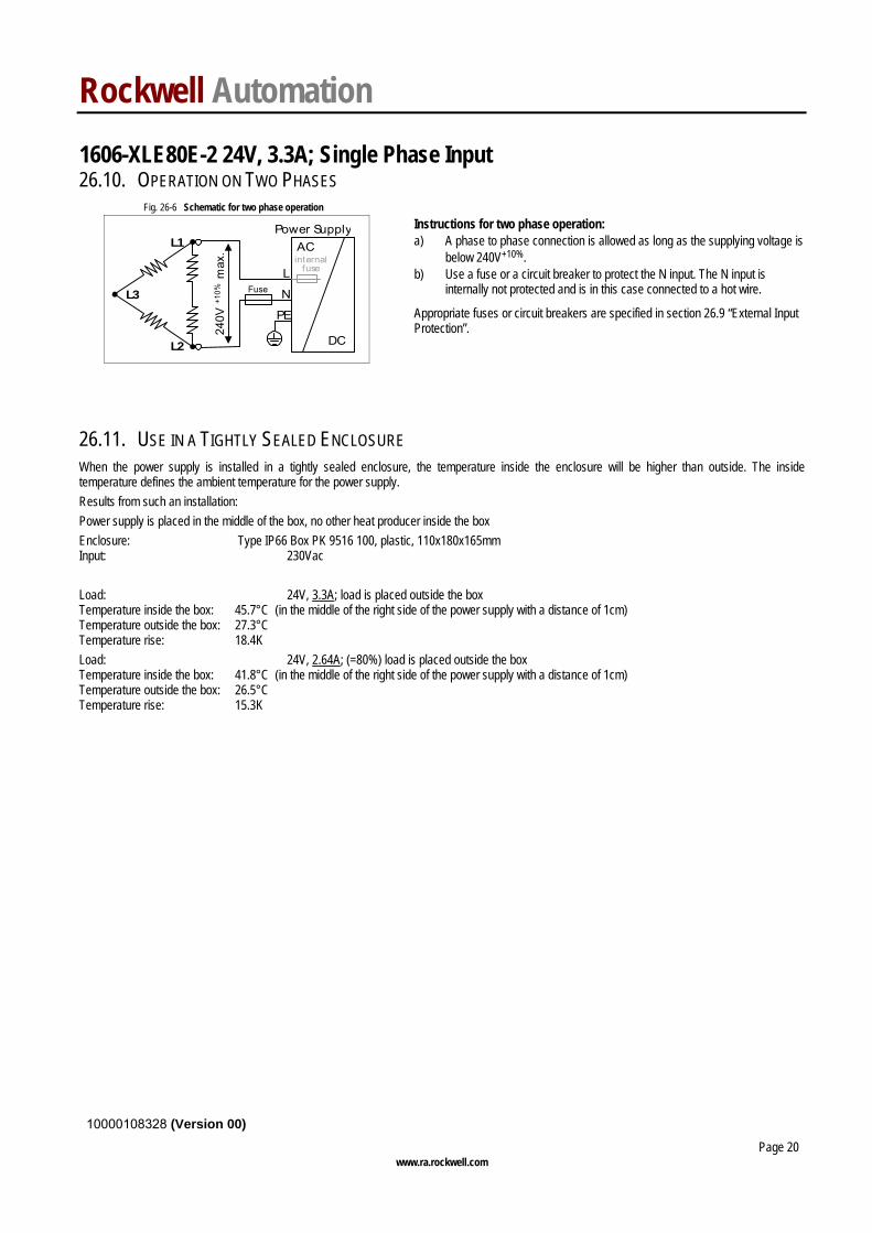
26.10. OPERATION ON TWO PHASES Fig. 26-6 Schematic for two phase operation
240V
+10%
max
.
Fuse
L2
L1
L3
L
N
PE
Power SupplyAC
DC
internalfuse
Instructions for two phase operation: a) A phase to phase connection is allowed as long as the supplying voltage is
below 240V+10%. b) Use a fuse or a circuit breaker to protect the N input. The N input is
internally not protected and is in this case connected to a hot wire.
Appropriate fuses or circuit breakers are specified in section 26.9 “External Input Protection”.
26.11. USE IN A TIGHTLY SEALED ENCLOSURE When the power supply is installed in a tightly sealed enclosure, the temperature inside the enclosure will be higher than outside. The inside temperature defines the ambient temperature for the power supply. Results from such an installation: Power supply is placed in the middle of the box, no other heat producer inside the box Enclosure: Type IP66 Box PK 9516 100, plastic, 110x180x165mm Input: 230Vac Load: 24V, 3.3A; load is placed outside the box Temperature inside the box: 45.7°C (in the middle of the right side of the power supply with a distance of 1cm) Temperature outside the box: 27.3°C Temperature rise: 18.4K Load: 24V, 2.64A; (=80%) load is placed outside the box Temperature inside the box: 41.8°C (in the middle of the right side of the power supply with a distance of 1cm) Temperature outside the box: 26.5°C Temperature rise: 15.3K

Rockwell Automation 1606-XLE80E-2 24V, 3.3A; Single Phase Input
10000108328 (Version 00)
www.ra.rockwell.com Page 21
26.12. MOUNTING ORIENTATIONS Mounting orientations other than input terminals on the bottom and output on the top require a reduction in continuous output power or a limitation in the max. allowed ambient temperature. The amount of reduction influences the lifetime expectancy of the power supply. Therefore, two different derating curves for continuous operation can be found below: Curve A1 Recommended output current. Curve A2 Max allowed output current (results approx. in half the lifetime expectancy of A1).
Fig. 26-7 Mounting Orientation A Standard Orientation
PowerSupply
OUTPUT
INPUT
Output Current
010 20 30 40 60°C
1
2
3
4A
50
A1
Ambient Temperature
Fig. 26-8 Mounting Orientation B (Upside down)
PowerSupply
OUTPUT
INPUT
Output Current
010 20 30 40 60°C
1
2
3
4A
50
A1
A2
Ambient Temperature
Fig. 26-9 Mounting Orientation C (Table-top mounting)
Output Current
010 20 30 40 60°C
1
3
4A
50
2A1A2
Ambient Temperature
Fig. 26-10 Mounting Orientation D (Horizontal cw)
Pow
erS
upply
OU
TPU
T
INP
UT
Output Current
010 20 30 40 60°C
1
3
4A
50
2A1A2
Ambient Temperature
Fig. 26-11 Mounting Orientation E (Horizontal ccw)
Pow
erS
uppl
y
OU
TPU
T
INP
UT
Output Current
010 20 30 40 60°C
2
3
4A
50
1
A1A2
Ambient Temperature