Embed Size (px)
Citation preview

Rocky Mountain RMRS Remediation Services. L.L.C. . . . pmtsctlng the envlmnmenf PROCEDURE OPERATION AND MAINTENANCE OF RMRS/OPS-PR0.084 STREAM-GAGING AND SAMPLING STATIONS
APPROVED FOR US
Revision 0 Date Effective: 09/15/98
Page 1 of44
TABLE OF CONTENTS
1 . PURPOSE .................................................................................................................................. 3
2 . SCOPE ....................................................................................................................................... 3
3 . REFERENCES .......................................................................................................................... 3 3.1 Source References ................................................................................................................... 3
. 3.2 Internal References ................................................................................................. : ................ 3 4 . LIMITATIONS AND PRECAUTIONS .................................................................................... 4
5 . PREREQUISITES ..................................................................................................................... 4
6 . INSTRUCTIONS ....................................................................................................................... 5 6.1 Operation of Automatic Samplers .......................................................................................... 5
6.1.2 Conversion from Sequential to Composite Sampling .......................................................... 7 6.1.2.1 Conversion of the Isco Model 3700R Refrigerated Sampler ............................................ 7 6.1.2.2 Conversion of the Isco Model 3700 Portable Sampler ..................................................... 7 6.2 Operation of Flow Meters ....................................................................................................... 8 6.2.1 Programming ........................................................................................................................ 8 6.2.2 6.3 Maintenance of Automatic Samplers .................................................................................... 12 6.3.1 Cleaning the Sampler ......................................................................................................... 13 6.3.2 Replacement of the Pump Tubing ...................................................................................... 13 6.3.3 6.3.4 6.3.4.1 6.3.4.2 Fuse Replacement ...................................................................................... 1 .................... 16 6.4 Maintenance Of Flow Meters ............................................................................................... 17 6.4.1 Care of the Flow-Meter Case ............................................................................................. 17 6.4.1.1 Careofthecaseseal ....................................... .............................................................. 17 6.4.1.2 Preventing Moisture Damage ......................................................................................... 18
6.1.1 Programming ........................................................................................................................ 5
Operation of the Bubble Rate Adjust Valve (Model 3230 Only) ....................................... 12
Changing the Internal Desiccant ........................................................................................ 15 Charging the Nicad and Lead-Acid Battery Packs ............................................................ 15
Charging ............................................................................................................... : .......... 16
ig%&i!l RErni’ SW-A -002707

OPERATION AND MAINTENANCE OF RMRS/OPS-PRO.O84 a; STREAM-GAGING A N D SAMPLING STATIONS Revision 0
5 0911 5/98 Page 2of44 . 6.4.2 Reactivation of the Desiccant ............................................................................................ 18 6.4.2.1 Checking and Regenerating the Internal Case Desiccant ............................................... 19 6.4.2.2 Regenerating the External Desiccant Cartridges ............................................................ 19 6.4.3 Bubble Line Maintenance (Model 3230 Only) .................................................................. 20 6.4.4 Maintenance of the Internal Plotter .................................................................................... 20 6.4.4.1 Changing the Paper Roll ................................................................................................. 20 6.4.4.2 Installing a New Paper Roll ............................................................................................ 21 6.4.4.3 Re-threading the Paper .................................................................................................... 21 6.4.4.4 Ink Ribbon Replacement ................................................................................................. 22 6.5 Flowlink Software Data Transfer .......................................................................................... 23 6.6 Documentation ...................................................................................................................... 23 7 . DISPOSITION ......................................................................................................................... 23
ATTACHMENTS
Attachment 1 Attachment 2 Attachment 3 Attachment 4 Attachment 5 Attachment 6 Attachment 7 Attachment 8 Attachment 9 Attachment 10 Attachment 11 Attachment 12 Attachment 13
Illustration 1 Illustration 2 Illustration 3 Illustration 4 Illustration 5
Automatic Sampler Description .......................................................................... 24 Automatic Sampler Operation ............................................................................ 25 Automatic Sampler Keypad Functions ................................................. .; ............ 26 Automatic Sampler Time-Paced Sequential Sampling ....................................... 27
Automatic Sampler Interactive State Structure ................................................... 30 Automatic Sampler Configure Option Functions ............................................... 31
Automatic Sampler Time-Paced Composite Sampling ...................................... 28
Flow Meter Description ...................................................................................... 32 Switch And Keypad Description ........................................................................ 33 Internal Plotter Description ................................................................................. 36
Nicad And Lead-Acid Battery Packs .................................................................. 38 Programming Overview ...................................................................................... 37
Internal Plotter Example Report ......................................................................... 39
ILLUSTRATIONS
Isco Model 3700R Refrigerated Sampler ............................................................ 40 Isco Model 3700 Portable Sampler ..................................................................... 41 1x0 Model 3220 Flow Meter Front Panel .......................................................... 42 1x0 Model 3230 Flow Meter Side View ............................................................ 43 24-Position Keypad .............................. ............................................................... 44

OPERATION AND MAINTENANCE OF STREAM-GAGING AND SAMPLING STATIONS
09/15/98
RMRS/OPS-PR0.084 Revision 0
Page 3 of 44
1.
2.
3.
3.1
3.2
PURPOSE
The purpose of this procedure is to establish protocols for the operation and maintenance of automatic sampling and flow-measurement equipment at stream-gaging and sampling stations at the Rocky Flats Environmental Technology Site (WETS). Procedures are described for the day-to-day operation and periodic maintenance of the equipment. Additional information is available in the instruction manuals for the specific equipment used at WETS.
SCOPE
These procedures apply to all personnel involved with stream gaging and surface-water sampling as part of the automated surface-water monitoring program at WETS. These procedures instruct the personnel in the correct execution of protocols for the operation and maintenance of the automatic samplers and flow meters used at stream-gaging and sampling stations included in this program.
REFERENCES
Source References
1.
2.
3.
4.
5 .
6 .
7.
Isco, Inc., 1990a. Instruction Manual for Model 3220 Flow Meter
Isco, Inc., 1990b. Instruction Manual for Model 3230 Flow Meter
1x0, Inc., 1990c. Instruction Manual for Model 3 700W3 740 Repigerated Sampler
1x0, Inc., 1990d. Instruction Manual for Model 3700 Portable Sampler
Isco, Inc., 1994a. Instruction Manual for FLOWLINK 3 Sofiware
Isco, Inc., 1994b. Instruction Manual for Model 4230 Flow Meter
Isco, Inc., 1994c, Instruction Manual for Model 4220 Flow Meter
Internal References
1. EG&G Rocky Flats, Inc., 1991% Work Plan for Event-Related Surface Water Monitoring and Sediment Characterization
EG&G Rocky Flats, Inc., 1991b. 5-21000-OPS-SW. 10: Event-Related Surface Water Sampling
EG&G Rocky Flats, Inc., 199 1 c. 5-2 1000-OPS-FO: Field Operations
2.
3.

OPERATION AND MAINTENANCE OF RMRS/OPS-PRO .084 STREAM-GAGING AND SAMPLING STATIONS Revision 0
091 1 5/98 Page 4of44
4. LIMITATIONS AND PRECAUTIONS
Stream-gaging and sampling crews will be responsible for the operation and maintenance of automatic samplers and flow meters as well as the transfer of collected data using the Isco FLOWLINK software.
5. PREREQUISITES
Personnel executing the protocols described in this procedure should be instructed in the operation of the automatic samplers and flow-measurement equipment used at the gaging and sampling stations. At least one person in each field crew should have one (1) year of field experience sampling either surface water or ground water. All field personnel should have satisfied Occupational Safety and Health Administration (OSHA) training requirements for work at hazardous waste sites (40 CFR 191 0.120). '
Each sampling crew is required to be equipped (at a minimum) with the following items during the operation and maintenance of stream-gaging and sampling stations:
0 Field Logbook
0 Replacement tubing 0 Field data transfer equipment (laptop computer)
0 Plotter paper

6. INSTRUCTIONS
This section contains information on the operation and maintenance of automatic samplers and flow meters.
6.1
6.1.1
e
OPERATION AND MAINTENANCE OF RMRS/OPS-PR0.084 STREAM-GAGING AND SAMPLING STATIONS Revision 0
0911 5/98 Page 5 of44
0
Operation of Automatic Samplers
See Attachments 1 and 2 for a description and overview of the 3700/3700R automatic samplers. Illustration 1 shows an Isco Model 3700R Refiigerated Sampler and Illustration 2 shows an 1x0 Model 3700 Portable Sampler.
Programming
NOTE: The Liquid Crystal Display (LCD) is used to prompt the user through the programming and configuration process and allows the user to monitor a running sample routine. The LCD is located on the control panel of both the Isco Model 3 700 and Model 3 700R samplers.
There are two types of displays: displays that communicate information about the sampler’s status and those which require input from the user via the keypad Displays which require input can be identified by a blinking word or number. The blinking word or number serves as a prompt for input.
Configuring and programming the Isco Model 3 700 and Model 3 700R samplers is accomplished by responding to displays andprompts on the LCD by using the keypad. The keypad is located on the control panel of both the Isco Model 3700 and Model 3700R samplers. Attachment 3 explains the function of each key on the keypad An audible beep should be heard when a key is pressed
Programming Steps - The steps to program the Isco Model 3700R or Model 3700 samplers are outlined below:
1. Turn the sampler on with the ON/OFF key. The sampler always “wakes” up in the “standby” state. The “STANDBY” message will appear or, if the sampler was turned off while running a routine, the “PROGRAM HALTED” message will be displayed. Both messages indicate that the sampler is in standby mode.
Press the ENTERPROGRAM key to access the interactive state. Select the program sequence. If the user wishes to return to a previous display during the programming sequence, he/she can press the EXIT PROGRAM key. The sampler will return to the standby state and the user can repeat steps 1 and 2 and then press the ENTElUPROGRAM key to scroll through the settings until the desired display is located.
2.

OPERATION AND MAINTENANCE OF RMRS/OPS-PRO.O84 I
STREAM-GAGING AND SAMPLING STATIONS Revision 0 0911 5/98 Page 6of44
3.
4.
5.
6.
7.
8.
9.
Enter the Sample Pacing settings. The sampler will prompt the user to select either time- or flow-paced sampling. The user will then be prompted to enter the time interval between samples or the flow-pulse interval.
Enter the Sample Distribution settings. The settings in the Sample Distribution section allow the user to perform sequential or multiplexed sampling. The first display asks the user if multiplexing is desired. Selecting “NO” means sequential sampling is desired. The sampler will then prompt the user for bottle volumes.
Enter the Sample volume settings. The Sample Volume section contains prompts for the sample volume. Depending on the selections made in the configure sequence, it may contain prompts for suction head and for sampler calibration. Because the actual sample volume varies by 10 ml, the user should enter a total sample volume that is slightly less than the volume of the bottle.
Enter the Key Times settings. In the basic programming mode, the user will be asked if he/she wants to enter a specific start time for the routine. If “YES” is selected, the user will be prompted to enter a start time &d date. If “NO” is selected, the sampler will use the start time delay. The start time delay can be set between 0 and 999 minutes in the Start Time Delay configure option.
The sampler will automatically return to standby.
From standby, press the START SAMPLING key to start the routine. This will place the sampler into the “run” state. If a start time delay has been entered, the delay begins when the START SAMPLING key is pressed. The user will be prompted to enter the starting bottle number. To begin with bottle 1, press the ENTERPROGRAM key. If no response is made within 60 seconds, the sampler will automatically begin with bottle 1.
Use the run state displays while running the sampling program to monitor the sampler’s progress.
NOTE: See Attachments 4 and 5 for step-by-step instructwns on how to program the sampler for time-paced sequential and time-paced composite sampling, respectively. These Attachments also illustrate the display that the user willfind on the LCD at each progranuning step. Illustration 5 shows the 24-position keypad on an Isco Model 3700 Portable Sampler.
The program sequence and the conjgure sequence are interdependent The selections made in the configure sequence determine what settings will be available in the program sequence. Attachment 6 illustrates the relationship of the program and configure sequences within the interactive state. Attachment 7 summarizes the options available in the configure sequence. Programming in the configure sequence is analogous to the programming sequence. The display prompts the user to make

OPERATION AND MAINTENANCE OF STREAM-GAGING AND SAMPLING STATIONS
09/15/98
RMRSIOPS-PR0.084 Revision 0
Page 7 of 44
selections using the keypad. The user can scroll through different configure options using the left and right arrows.
6.1.2 Conversion fiom Sequential to Composite Sampling
Several adjustments must be made to both the Isco Model 3700 Portable Sampler and the Isco Model 3700R Refrigerated Sampler to prepare them for composite sampling. These adjustments are easily reversed to return the sampler to a sequential sampling mode.
6.1.2.1 Conversion of the Isco Model 3700R Refrigerated Sampler
Conversion of the Isco Model 3700R sampler requires the following steps:
1 .
2.
3.
Remove the sample bottle rack or the bottle locating base.
Unscrew the distributor arm nut and remove the distributor arm. Replace the pump tubing with 40.5-inch composite pump tubing. Route the tubing into the refrigerator and through the hole in the support bracket. The support bracket is located directly in fiont of the distributor arm.
Place the composite bottle in the sampler and route the tubing through the hole in the bottle top.
4.
6.1.2.2 Conversion of the Isco Model 3700 Portable Sampler
Conversion of the Isco Model 3700 Portable Sampler is similar to the procedure described above except that-a float cage assembly must be attached to the hole in the I
distributor shaft, and a composite bottle locating deck must be installed in the sampler base. Conversion of the 1x0 Model 3700 Portable Sampler requires the following steps:
1 .
2.
3.
4.
5.
Remove the sample bottle rack or the bottle locating base.
Unscrew the distributor arm nut and remove the distributor arm. Install the float and float cage. The shaft on the float should be installed in the hole in the distributor shaft. The float cage is attached to the underside of the center section using the four screws and 1 -inch spacers provided with the float cage kit. When attaching the cage, reuse the existing lock washers. The float cage should be aligned so that the tubing guide is facing the pump tubing port.
Feed the 34.5-inch composite pump tubing through the port in the center section. Feed the tubing into the float cage tube guide.
Insert the locating deck, open side down, in the sampler base. Reassemble the sampler.

OPERATION AND MAINTENANCE OF STREAM-GAGING AND SAMPLING STATIONS
RMRSIOPS-PR0.084 ,
Revision 0 0911 5/98 Page 8 of 44
6.2 Operation of Flow Meters
See Attachment 8 for a description of the 1x0 flow meters. Attachment 9 describes the switch and keypad in detail and Attachment 10 describes the internal plotter. Illustration 3 shows an Isco Model 3220 Flow Meter front panel and Illustration 4 shows an Isco Model 3230 Flow Meter side view.
NOTE: The flow meter LCD is used to prompt the user through the set-up program, to display current program parameters, and to display total flow, present flowrate, and level. The display may be viewed through the window on the front door of theflow meter's cabinet when the door is closed The display is a 2-line, 40-character, dot matrix liquid crystal.
Low Power Indication - When power to the meter falls too low for the unit to operate properly, the message "POWER LOSTLO W BATTERY'' will appear on the top line of the display. When power is lost or falls below operating limils, the flow meter will stop accumulating data, and the internal plotter will not prinl. However, stored data and program parameters entered into memory will be retained by the internal battery- backed RAM.
6.2.1 Programming
1x0 Flow Meter models 3220,4220,3230, and 4230 are programmed with the aid of the dot matrix display. The keypad is used to enter program parameters and to control certain flow meter functions. The display is used to show both menu selections available and selections chosen. The entry selected will flash on the display. The display also indicates operational status and guides the user through the flow-meter programming sequence by showing the step being programmed. Each time a key is pressed an audible signal is emitted. See Attachment 11 for an overview of flow-meter programming and program steps.
NOTE: The following programming sequence is designed for a speciflc event-related surface-water sampling scheme. Changes other than for this speciflc programming sequence can be made, and the user is advised to consult the instruction manual referenced in Section 3.0. Enter the program by pressing the "ENTER PROGRAM STEP" key then select choices from the menus presented on the display.
1.0
Select "NORMAL" for operation in the normal mode when a primary flow-measurement device such as a flume or weir is present, then press "ENTER." Otherwise select "LEVEL ONLY" for measurement of water flow in channels or culverts, then press "ENTER." Selecting "LEVEL
1. NORMAL 2. LEVEL ONLY
ONLY" will result in a request that units to measure be entered. Select "FEET," and the program will then skip to step 2.0.
OPERATION AND MAINTENANCE OF STREAM-GAGING AND SAMPLING STATIONS
RMRS/OPS-PRO. 084 Revision 0
09/15/98 Page 9of44
1.1 SELECT FLOW CONVERSION TYPE 1. STD 2. EQN 3. MANN 4. DATA 5. PROM
Select "STD" for standard flow conversion for flumes and weirs, then press "ENTER."
1.2 ENTER MAX HEAD - RANGE XXXX-XXXX MAX HEAD IN (Units) = XXX (Units)
Select a value for MAXHEAD that is the highest water level that will occur in the given flume or weir (read from top of staff gage). The flow meter's internal resolution is based on this value. (Units = Feet, as selected in step 1.3).
SELECT UNITS OF LEVEL MEASUREMENTS 1. FEET 2. METERS
1.3
Select "FEET", then press "ENTER"
1.4 SELECT FLOW RATE UNITS 1. GPM 2. GPS 3. MGD 4. CFS 5. OTHER
Select "CFS" for cubic feet per second, then press "ENTER."
1. CF 2. GAL 3. CM 4. AF 5. L 6. MGAL 1.5 SELECT TOTALIZED VOLUME UNITS:
Select "CF" for cubic feet, then press "ENTER."
1.6 SELECT TYPE OF STANDARD DEVICE: 1. WEIR 2. FLUME
Select "FLUME," then press "ENTER." By selecting "FLUME," the program will go to step 1.7.
1.7 SELECT TYPE OF FLUME: 1. PAL-BOW 2. PARS 3. TRAP 4. H
Select "PARS" for Parshall flume, or 'H" for H flume, then press "ENTER."
1. 1" 2. 2" 3. 3" 4.6" 5. 9" 6. 12" 7. 18" 8. 24" 9. 36" 1.8 SELECT SIZE:
Step 1.8 will be displayed if "PARS" was selected in step 1.7. Select the size of the flume, then press "ENTER."
1.9 SELECT SAMPLER FLOW PACING 1 .OFF 2.ENTER FLOW INTERVAL
For timed-paced sampling, select "OFF," then press "ENTER."
2.0 SELECT SAMPLER CONTROL 1. ENABLE 2. DISABLE 3. ENABLE BY LEVEL
Select "ENABLE BY LEVEL," then press "ENTER."
2.1 ENTER LEVEL AT WHICH TO ENABLE SAMPLER: X.XXX FT
Enter the level desired for sampling initiation. This will cause the sampler to be enabled at and above this level.
2.2 SELECT PLOTTER ON/OFF WITH SAMP ENAB: 1.YES 2. NO

OPERATION AND W T E N A N C E OF RMRSIOPS-PR0.084 ,
STREAM-GAGING AND SAMPLING STATIONS Revision 0 Page 10 of 44 0911 5/98
If "YES," is selected, the plotter will be turned on or off when the sampler is enabled or disabled, respectively. The plotter will not turn off with the sampler until it has printed a time- anddate line on the chart. When stopped, the plotter will print a line similar to: >-c, which will cross the entire chart. This line alerts the user that the chart generated by the plotter has not been running continuously.
Step 3.0 will be displayed if 'NORMAL" was selected in step 1 .O.
3.0 SELECT PLOTTER MODE OF OPERATION: 1. OFF 2. LEVEL 3. FLOW
For this programming exercise, select "FLOW," and press "ENTER."
Step 4.0 will be displayed if "LEVEL ONLY" was selected in step 1 .O.
4.0 SELECT PLOTTER MODE OF OPERATION: 1. OFF 2. LEVEL
Select "LEVEL," and press "ENTER."
If "LEVEL" was selected in step 3.0 of 4.0, then step 5.0 will be displayed.
5.0 ENTER PLOTTER FULL-SCALE READING: 100% LEVEL = xx.m FT
Enter the 100% level, then press "ENTER." For event monitoring, the 100% level should be equal to the MAX HEAD for the particular primary flow-measurement device or estimated maximum head for the channel or culvert.
If "FLOW was selected in step 3.0, then step 6.0 will be displayed.
6.0 ENTER PLOlTER FULL-SCALE READING: 100% FLOW = XXXXXX CFS
Maximum flow will be automatically displayed based on the size of the primary flow- measurement device. Press "ENTER" to accept this value.
7.0 SELECT PLOTTER CHART SPEED: 1. 0.5"/H 2. 1"/HR 3.2"/HR 4.4"/HR
Select '0.WHR" to conserve plotter paper.
8.0 SET: YEAR MONTH DAY HOUR MINUTE xxxxxxxxxxxx
Enter the current date and time.

OPERATION AND MAINTENANCE OF RMRS/OPS-PRO.O84 STREAM-GAGING AND SAMPLING STATIONS Revision 0
0911 5/98 Page 11 of44
9.0 ENTER SITE IDENTIFICATION NUMBER: SITE NUMBER = XXX
Enter the site identification number that will be printed on the chart and may be used for subsequent identification of the chart record. Use the GS designation for the station. For example, if the station is GS03, enter 003.
1
12.0 SELECT RESET FLOW TOTALIZER: 1. YES 2. NO
Select "NO," then press "ENTER."
10.0 SELECT AUTO PURGE FREQUENCY 1. OFF 2. 5 3. 10 4. 15 5. 30 6. 60
The units are in minutes.
11.0 ADJUST LEVEL: UPIDOWN OR VALUE ENTER PRESENT LEVEL: 2 XX.xMx FT
Measure the actual water level in the channel using a staff gage and enter the value, then press "ENTER."
I I
13.0 REPORT GENERATION 1. ON 2. OFF 3. PRINT
Select "PRINT" for a report printout, then press "ENTER."
13.1 CLEAR REPORT DATA AFTER PRINT: 1.YES 2. NO
If "YES" is selected, the minimum level, maximum level, minimum flow, maximum flow, average flow, and the volume for the period will be cleared and the next report will cover the period from the present to the next report time.
13.2 REPORT INTERVAL TO BE IN: 1. HOURS 2. DAYS 3. MONTHS
Select 'HOURS," then press "ENTER."
13.3 ENTER INTERVAL IN HOURS: XXXX HOURS
Enter '24," then press "ENTER."
13.4 ENTER THE INTERVAL START TIME: YR:YYYY M0NTH:MM DAY:DD HR:HH MIN:MM
Enter the current year, month, day. Enter "0000" for hour and '0" for minute, then press "ENTER."
OPERATION AND MAINTENANCE OF RMRSIOPS-PRO .084 ,
STREAM-GAGING AND SAMPLING STATIONS Revision 0 09/15/98 Page 12 of 44
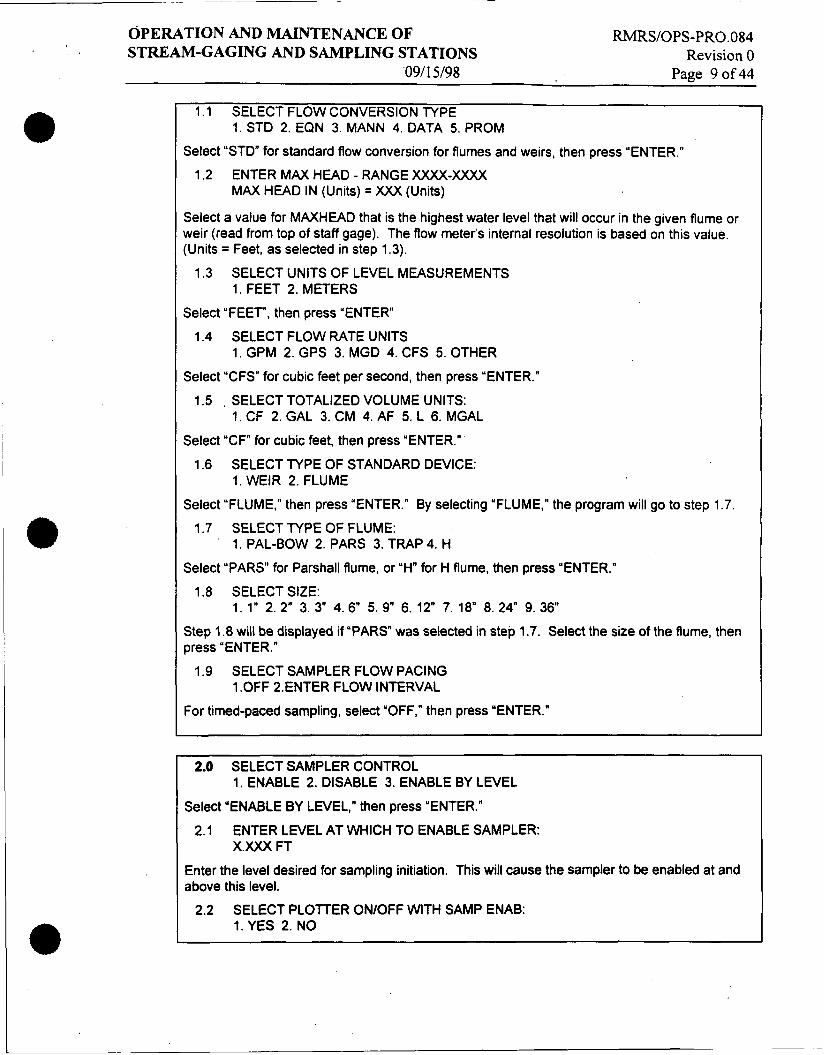
14.0 ENABLE PROGRAM LOCK? 1. YES 2. NO
The programmed parameters can still be viewed, but not altered, when the "LOCK" is enabled (the unlock code number for the flow meter is the model number, 3220,4220, 3230, or 4230). If the "LOCK" is enabled, the letter "L" will appear at the right side of the display when the flow meter is operating in the normal mode (displaying level or flowrate). If the user enters the program to make changes, the display will ask for the password (3220, 4220, 3230, or 4230). After the changes have been installed and the user exits the program, the program will lock and the "L" will reappear on the display after about 30 seconds. The "L" will stay off only if "NO" is chosen in step 14.0.
' 6.2.2 Operation of the Bubble Rate Adjust Valve (Model 3230 and 4230 Only)
This valve, located on the right side of the flow meter's case, is a "needle" type valve that controls the rate at which compressed air is bled from the reservoir into the bubble tube and the rate at which the bubbles are released into the flow stream. To operate the Bubble Rate Adjust Valve:
1.
2.
Turn the valve knob counterclockwise to increase the bubble rate.
Turn the knob clockwise until it stops completely to shut off the air supply to the bubble line.
Set the bubble rate at approximately one (1) bubble per second. For relatively clean flow streams, a bubble rate of one (1) bubble per second will provide the required sensitivity while at the same time minimizing power consumption.
Set the bubble rate at approximately two (2) bubbles per second for flow streams with suspended solids (e.g., domestic raw sewage or streams with a high grease content). A bubble rate of two (2) bubbles per second will aid in preventing clogging of the bubble line at the expense of higher power consumption.
'
3.
4. '
NOTE: Do not use anything butfingers to tighten the Bubble Rate Adjust Valve. The needle and the seat inside the valve are very small and may be damaged or broken if tools or excessive force are used to force the valve when closing it. Once the valve is properly set, do not use excessive force to tighten the hex screw that locks the adjustment knob or either the wrench or hex screw may be stripped
6.3 Maintenance of Automatic Samplers
This section contains procedures for routine, quarterly maintenance of automatic sampling equipment in use at the stream gaging and sampling stations: Information that addresses non-routine maintenance such as equipment failure or breakage, or other

OPERATION AND MAINTENANCE OF RMRS/OPS-PRO.O84 STREAM-GAGING AND SAMPLING STATIONS Revision 0
09/15/98 Page 13 of 44
6.3.1
6.3.2
maintenance issues not covered in this section, can be found in the instruction manuals referenced in Section 3.0 of this procedure.
Cleaning
Primary flow-measurement devices (flumes and weirs) should be inspected each time a site is visited, and any debris that is present should be removed. Also, sample bottles must be cleaned thoroughly after each use.
NOTE: Pump tubing and suction line will not require-cleaning because of the automatic purge capability of the automatic samplers that will condition the tubing prior to the collection of each sample. Water or cleaning solution can be pumped through the tubing to clear an obstruction or clean the tubing in a special case. If a cleaning solution is used, the tubing must be rinsed thoroughly before the next sampling event. Ifthe sampling crew has any reason to believe that either the sample tubing or the pump tubing has become contaminated, the tubing should be replaced
Replacement of the Pump Tubing
NOTE: The constant mechanical strain placed on the tubing by the action of the peristaltic pump, as well as chewing by small mammals such as mice, will eventually cause the tubing to fail. The pump tubing should be inspected periodically for wear inside the pump by removing the cover. The tubing should be inspected for cracks where the pump roller compresses the tubing. The tubing 1iJe configure option reports the number of pump counts elapsed during the life of the pump tube.
Removing the Pump Tubing - The following steps should be followed to remove the pump tubing:
1.
2.
3.
4.
5 .
Disconnect power from the unit.
Separate the center section from the rest of the sampler. Turn center section over to access the distributor assembly. (This step is not necessary on the Isco Model 3700R sampler because the distributor assembly can be accessed by opening the door to the refiigerator compartment).
Unscrew the distributor arm retaining nut. Pull arm off of distributor shaft. Do not manually rotate the distributor adshaf t .
Pull the pump tubing out of the distributor arm and coil spring assembly. (Isco Model 3700R samplers are not equipped with a coil spring assembly).
Pull the tubing out of the pump tubing port in the center section.

OPERATION AND MAINTENANCE OF STREAM-GAGING AND SAMPLING STATIONS
RMRSIOPS-PRO. 0 84 Revision 0
0911 5/98 Page 14 of 44
Remove the outer case of the liquid detector. This is done by loosening the two captivated thumbscrews that fasten the case to the liquid detector housing. Next, pull the tubing away from the detector.
Remove the outer pump cover. This is done by looseriing the four captivated thumbscrews that fasten the pump cover to the pump housing. This will expose the pump tubing.
Extract the tubing from the pump. The pump rollers can be rotated manually to facilitate the removal of the tubing. When the tubing has been removed. thoroughly clean the interior of the pump casing.
Remove the suction line, if attached. Loosen the clamp which secures the line to the pump tubing and disconnect the suction line from the pump tubing.
6.
7.
8.
9.
Installing a New Pump Tube - The following steps should be followed to replace the pump tubing:
1.
2.
3.
4.
'5.
6. 7.
8.
9.
Line up black bands on the new pump tubing. These bands are used to correctly locate the tubing in the detector and pump. Correct placement is critical to prolonging the life of the pump tubing and to assuring efficient operation and accurate sample volumes. Facing the liquid detector, place the inner edge of the end band against the upper left inlet of the liquid detector. Place the inner band at the lower outlet of the liquid detector.
Slip the pump tubing under the pump rollers. Tubing should be situated so that the pump tubing does not interfere with the installation of the outer pump cover.
Check the position of the black marker bands. Adjust the tubing if the position of the bands indicate that the tubing has slipped.
Replace the outer cover of the liquid detector. Secure the cover in place by tightening the two thumbscrews.
Replace the pump cover and tighten the four thumbscrews.
Feed the tubing through the pump tubing port in the center section.
Feed the tubing through the coil spring (Isco Model 3700 only) and distributor arm. The end of the tubing should be installed flush to the lip protruding 1116- inch fiom end of the distributor arm. Reinstall the distributor arm. Align the distributor arm on the distributor shaft and screw in the retaining nut. Make sure the retaining nut is tight.
Inspect the length of exposed tubing under the center section. There should be no excessive slack in this tubing; it should slope continuously downward from the bottom of the center section to the point where it enters the distributor arm. This prevents low spots in the tubing where liquid could pool and prevent

OPERATION AND MAINTENANCE OF RMRS/OPS-PR0.084 STREAM-GAGING AND SAMPLING STATIONS Revision 0
09/15/98 Page 15 of 44
complete drainage. Slack can be adjusted by pulling the tubing out of the pump tubing port.
10. Reinstall the suction line.
1 1. Reset the pump tubing count to zero. This is done through the Tubing Life configure option (consult the instruction manual referenced in Section 3.0).
6.3.3 Changing the Internal Desiccant
NOTE: A humidity indicator, labeled “INTERNAL CASE HUMIDITY, ” is located in the lower left corner of the control panel. It indicates the amount of moisture present inside the control born The paper indicator is blue in a dry state. If moisture accumulates inside the control box, the numbered areas on the indicator will turn light pink or white. The indicator has three sections numbered 20,30, and 40, indicating the percent humidity in the control born If the indicator section marked 30 turns white or pink, the desiccant inside must be renewed or replaced
To change the internal desiccant:
1. ,
Unscrew the screws located around the outer rim of the control box bezel, and lift the bezel and cover off the control box.
2.
3.
Replace or renew the three bags of desiccant. The desiccant bags can be renewed by placing them in an oven at 250°F for 16 hours.
Inspect the control box for leaks while it is open. If a leak is found, it can be repaired by following procedures detailed in the Isco Model 3700 Portable Sampler Instruction Manual, (Isco, Inc., 1990d, Sec. 6.5 and 6.7), or by returning the control box to the factory.
Coat the cover gasket with a thin film of silicone grease. 4.
5. Reseal the control box.
6. Tighten the screws that fasten the control box cover using an even cross- torquing pattern.
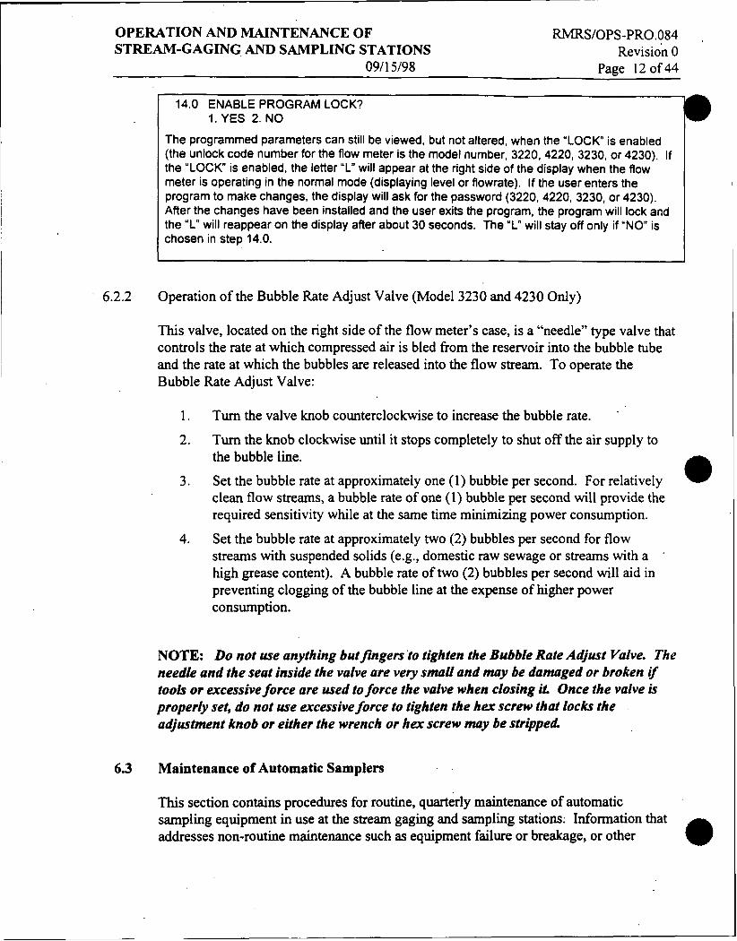
6.3.4 Charging the Nicad and Lead-Acid Battery Packs.
The Isco Model 3700 and Model 3700R samplers may be supplied with nickel-cadmium (nicad) and lead-acid battery packs as primary power supplies for sampling and gaging stations without an AC power source, or as secondary “backup” supplies in case of AC power failure.
L

OPERATION AND MAINTENANCE OF RMRS/OPS-PR0.084 STREAM-GAGING A N D SAMPLING STATIONS Revision 0 '
NOTE: Both the Isco Model 3700 and the Model 3700R samplers can be powered from an Isco AC Power Pack, from an Isco Nicad Battery Pack, or from an external 12 Volt DC Lead-Acid battery. The power pack may also be used to charge the batteries.
The following sections describe the use and changing of the nicad and lead-acid batteries. I
6.3.4.1 Charging I CAUTION - CHARGING: The nicad battery pack should only be charged with an Isco Power Pack, Battery Charger, or Five Station Battery Charger. AN will supply the proper DC charging current to the battery when they are connected to an ACpower source. Chargers designed for Iead-acid batteries, such as automotive or gelled- electrolyte types, are not satisfactory because their open-circuit voltage is generally not high enough to fulIy charge a nicad battery; consequent& they are not recommended
The lead-acid batteries should be charged with an Isco AC Power Pack. The AC Power Pack will suppIy a regulated DC charging current to the lead-acid battery when connected to an appropriate AC line source. The charge level of the lead-acid battery can be determined by measuring the output voltage. A chart is provided on the side of the battery that lists the level of charge and time required to recharge for various output voltages.
CAUTION - OVERCHARGING: Overcharging the battery causes it to overheat, gradually breaking down separator material inside the battery. Repeated overcharging will reduce the useable life of the battery and should be avoided If an Isco Power Pack is used, the battery may be overcharged occasionally with little loss of capacity.
To charge a battery:
1. Connect the plug on the battery cable to the mating receptacle on the power pack or to the connector on the battery charger.
Plug the power pack or five station battery charger into any standard 110-V grounded wall outlet.
2.
See Attachment 12 for more information regarding charging nicad and lead-acid packs.
) 6.3.4.2 Fuse Replacement
If the internal fuse link is blown, the battery fuse will have to be replaced by performing the following:
I
a

OPERATION AND MAINTENANCE OF STREAM-GAGING A N D SAMPLING STATIONS
09/15/98
RMRS/OPS-PRO.084 Revision 0
Page 17 of 44
6.4
6.4.1
' 6.4.1.1
1.
2. Remove the four screws holding the battery cover.
Remove the cover. This will expose the blown fuse link and battery wires. The fuse is a two-inch length of #22 AWG copper wire; this wire is available from Isco.
Cut away the ends of the blown fuse wire.
Solder in a new link where the old wire was attached.
Insulate with tape or shrink tubing.
Replace the cover. Be careful to place the cord strain relief ferrule just inside the case so that the cord may not be accidentally pulled out.
3. 4. 5. 6.
MAINTENANCE OF FLOW METERS
This part of the procedure provides detailed instructions on the care and routine maintenance necessary to keep the flow meter in top operating condition.
NOTE: Primary flow-measurement devices (flumes and weirs), channels, and culverts should be inspected each time a site is visited and any debris that is present should be removed
Care of the Flow Meter Case
If the lid is tightly latched and the Military Standard (WS) connectors on the side of the case are tightly capped, the case may be cleaned by performing the following:
1. Spray the case with a hose or wash it with soapy water.
NOTE: Do not use a hose with a nozzle or a high pressure hose-and-wand such as is found at car washes. Do not immerse thejlow meter in a tank of water to wash it. While designed to withstand accidental submersion in water should that occur, the
flow meter is not intended for routine submersion.
Care of the Case Seal
The case seal should be inspected and cleaned when necessary by performing the following:
1. Inspect the ridge that extends around the edge of the back half of the flow meter cabinet. This ridge forms a seal with the groove in the cabinet door and should be fiee of dirt, sand, etc.

OPERATION AND MAINTENANCE OF RMRS/OPS-PRO.O&I STREAM-GAGING AND SAMPLING STATIONS Revision 0
0911 5/98 Page 18 of44
2.
3. Wipe the above described ridge carefully with a damp cloth if it isn’t clean.
Clean the rubber gasket in the lid. It may be cleaned with a small brush a damp cloth.
NOTE: If any of these cleaningprocedures are performed while the case is open, be careful not to allow any dirt or debris to fall inside thejlow-meter case. It b best to work on the flow meter with the case standing upright. If the seals are not properly maintained, they may leak, causing damage and eventual failure of the components inside.
6.4.1.2 Preventing Moisture Damage
To prevent moisture damage to internal components, the following steps must be observed:
1 .
2.
3.
4.
Tightly latch the lid at all times. Open the case lid only when it is necessary to access the front panel to change the program or change the paper roll.
Inspect weekly and recharge the desiccant canister as necessary.
Keep the external connectors clean by keeping the mating connectors of the protective caps tightly screwed down.
Under severe operating conditions, spray the threads of the connectors with a cleaner/lubricant (such as J I F T M manufactured by GC Electronics or W D - 4 0 T M manufactured by the WD-40 Company) to prevent corrosion. Be careful not to spray any of the conductive terminals (pins or jacks) inside the connectors; residue from the sprays could cause intermittent or failed contacts.
NOTE: Do not routinely operate the jlow meter with the case open. Doing so will expose the internal components to dirt and moisture; it will also cause the desiccant canister inside the case to be prematurely spent
6.4.2 Reactivation of the Desiccant
NOTE: Both Iscojlow meter models are equipped with a re-usable desiccant canister attached by two thumbscrews to the inside of the flow meter’s lid and two tubular desiccant cartridges mounted on the right side of the case next to the connectors. The canister contains silica gel that adsorbs moisture trapped inside the flow meter’s case when it is closed, keeping the inside of the case completely dry during shipment, storage, and use. If the case is left open, the desiccant will adsorb moisture from the surrounding air. Eventually, its adsorption capacity will be reached, and it will no longer be able to protect the internal components of the flow meter.

OPERATION AND MAINTENANCE OF STREAM-GAGING AND SAMPLING STATIONS
RMRS/OPS-PRO . 0 84 Revision 0
e
0911 5/98 Page 19 of 44
6.4.2.1 Checking and Regenerating the Internal Case Desiccant
1.
2.
3.
4.
5.
Inspect the desiccant canister each time the case is opened. The desiccant canister has a window on its side that looks blue when the desiccant is in good condition. As the desiccant adsorbs moisture, the window will turn pink. When the window is pink, the desiccant needs to be regenerated or replaced with the spare canister provided in the flow meter’s accessory package.
Remove the canister from the flow meter by first loosening the two thumbscrews which hold the canisters mounting bracket down.
Remove the canister from the mounting bracket.
Heat the canister in an oven at 300°F (1 50°C) for about three hours or until the blue color returns. Do not use a microwave oven.
Reinstall the canister in the flow meter after cooling. Make sure the window on the side of the canister remains visible.
6.4.2.2 Regenerating the External Desiccant Cartridges
NOTE: The external desiccant cartridges may be inspected at the same time as the internal desiccant canister, or whenever the j low meter’s battery is changed. As long as the color is blue the desiccant is “safe” and need not be regenerated The cartridges willfirst begin to turn pink at one end of the plastic tubing as water is ahorbed. As time passes, the pink color will spread through the rest of the desiccant until eventually, the cartridges will become pink throughout their length. Before either cartridge has changed color completely, the desiccant should be regenerate&
To regenerate either or both cartridges:
1.
2.
3.
4.
5 .
6 .
Snap the cartridges out of the brackets which hold them attached to the flow meter’s case, one at a time.
Gently detach the silicone tubing from the top of each cartridge.
Pull one of the end caps off the cartridge.
Pour the spent desiccant into a small metal pan or some other container.
Refill the cartridge with the extra desiccant provided.
Replace the end caps. Note the cotton filters in the end caps. These are to prevent small pieces of the desiccant material falling out of the cartridge. These filters should be replaced periodically using ordinary. surgical cotton balls.
Regenerate spent desiccant by placing the particles in a shallow layer in the bottom of a small metal pan.
7.

OPERATION AND MAINTENANCE OF RMRSIOPS-PRO.084 ,
STREAM-GAGING AND SAMPLING STATIONS Revision 0 0911 5/98 Page 20of44
8. Heat at 400'F (299' to 225°C) in a clean atmosphere for one to two hours, or until the blue color returns.
The bubble line on the Isco Model 3230 and Model 4230 should be periodically inspected to make sure that it is not kinked, frayed, cut, nicked, or otherwise damaged. If the bubble line is found to be damaged, it should be replaced. A leaky or obstructed line may cause erroneous level readings and/or decreased battery life as a result of the pump having to run more frequently. If it becomes necessary to replace the bubble line, a new bubble line may be installed.
The outlet of the bubble line should be inspected periodically to ensure that it has not become obstructed due to accumulation of foreign material or organic growth. If the line is found to be obstructed, it should be cleaned or the top may simply be cut off. If clogging of the outlet of the bubble line proves to be a continuing problem, it may be desirable to use a bubble line with a larger inside diameter. However, it is usually preferable to increase the frequency of the automatic purge operation (see the following note). Consult the factory for specific recommendations regarding the size of the line, special connectors required, etc.
NOTE: The Isco Model 3230 and Model 4230 is equipped with an automatic purge feature to clear the bubble line with a discharge of air from the pump periodically. This may be useful as an aid in keeping the outlet of the bubble line clean. The program step SELECT PURGE INTERVAL allows the user to establish the interval between purge cycles, which ranges from five minutes to one hour. The purge button on the flow meter's front panel keypad also allows the user to purge the bubble line. Operation of the purge can readily be identified by the sound of the pump running inside the flow meter. The pump will continue to run for as long as the button is pressed, and for a few seconds after the button is released
6.4.4 Maintenance of the Internal Plotter
The internal plotter will be used under normal WETS operations and requires little periodic maintenance beyond changing the paper roll and changing the ink ribbon.
6.4.4.1 Changing the Paper Roll
NOTE: Refer to the illustration inside the front of the cabinet on the Isco Model 3220 and Model 3230. The roll of paper should be changed when it runs out, as the internal plotter will shut down when there is no paper in it The end of the roll is near when a 1-inch pink band appears on the left side of the chart

e
OPERATION AND MAINTENANCE OF STREAM-GAGING AND SAMPLING STATIONS
0911 5/98
RMRSIOPS-PRO.OS4 Revision 0
Page 21 of 44
To change the,roll of paper:
1.
2.
Locate the handle on the left side of the take-up roll.
Pull gently, but firmly, straight out on this handle until the take-up roll assembly comes off of the internal plotter mechanism.
Remove the roll from the take-up spool by holding the handle and gear of the take-up spool in the left hand while pulling the paper roll off the spool with the right hand.
Remove the feed spool by pulling gently on the handle protruding from the right side of the internal plotter assembly.
Remove the spent roll from the spool by holding the handle in the right hand and pulling the roll from the spool with the left hand.
3.
4.
5 .
6.4.4.2 Installing a New Paper Roll
After the spent roll has been removed:
1.
2.
3 .
4.
5 .
6.
Slide the new roll onto the feed spool so that it unrolls from the back side,. facing away. Do this by lining up the slots in the cardboard tube with the raised guides on the feed spool.
Peel the paper back gently so that it will unroll freely.
Using a knife or scissors, cut the end off the roll if it is tom; then fold it over on itself so that the end is straight and a little stiffer than a single thickness of paper would be.
Unroll a few inches of the paper and set the roll on the top of the flow meter’s cabinet.
Feed the paper down the back of the internal plotter with fingers to where it touches the roller. Make sure the paper gets past the lever for the paper sensing switch.
Press the CHART ADVANCE key and hold it down until the paper is fed through the internal plotter mechanism.
6.4.4.3 Re-threading the Paper
When the new paper has come through the internal plotter:
1.
2.
Reinsert the feed spool with the new roll on it into the internal plotter assemble.
Run a few inches through the internal plotter, using the CHART ADVANCE key.
L

- ~~
OPERATION AND MAINTENANCE OF RMRS/OPS-PRO.O84 STREAM-GAGING AND SAMPLING STATIONS Revision 0
Page 22 of 44 09/ 15/98
3.
4.
5 .
6.
Unfold the end that was folded over on the take-up spindle.
With a small piece of tape, tape the end of the new paper to the cardboard tube from the old roll.
Roll some of the paper onto the spool so that it will wind clockwise, facing away.
Re-insert the take-up roll into the top of the internal plotter. Be careful to push it all the way back in, so that the take-up gear on the end of the spool assembly will re-engage.
When the take-up spool is back in place, again push the CHART ADVANCE key; this will remove any slack in the paper.
7.
. 6.4.4.4 Ink Ribbon Replacement
NOTE: It is dijjficult to predict how long an ink ribbon will last, as the frequency of use of the internal plotter and report generator will vary from one installation to another. However, after a long period of operation and when the charactersprinted on the chart start to become faint, the ink ribbon should be replaced Whenever possible, ink ribbon replacement should be performed at the same time the roll of paper, is replaced, as it is easier to replace the ink ribbon when the roll of paper is out of the way. Refer to the illustration inside the front of the cabinet on the Isco Model 3220 and Model 3230.
To replace the ink ribbon:
1. Turn the unit off.
2. If there is still paper in the unit, remove the take-up spool and unroll enough paper to get it out of the way so that the two ink ribbon spools can be clearly '
seen. Each spool has a ribbon-detecting lever pressing against the ink ribbon. Note the direction in which the ink ribbon comes off the left spool and how it goes back onto the right spool.
Grasp one of the spools and rotate it slightly, loosening the ink ribbon.
Lift gently until the spool comes free from its shaft. Do the same thing with the other spool.
Lift the chart and take-up spool out of the way.
Remove the ink ribbon from around the printer mechanism, noting how it is threaded through.
7. Place the new ink ribbon around the printer mechanism.
8. Locate the three small pins on each spool of the ink ribbon.
9. ' Turn the spools so the pins face the gears on the two ribbon shafts.
3.
4.
5.
6 .

OPERATION AND MAINTENANCE OF STREAM-GAGING AND SAMPLING STATIONS
RMRS/OPS-PR0.084 Revision 0
091 1 5/98 Page 23 of44
10.
1 1.
12.
Replace the two spools on their respective shafts, pushing the detector levers out of the way so that spools will easily re-engage their gears.
Gently rotate each spool to tighten the ink ribbon.
Reinstall the paper take-up roll if necessary. The procedure outlined above will also be followed if the roll of paper is being replaced.
6.5 Flowlink Software Data Transfer
NOTE: A laptop computer with Isco FLO WLINK software is required for the retrieval of data other than the printed data produced from the internal printer/plotter. Data must be collected periodically to avoid losing data If a memory partition is filled, past collected data is erased as new data replaces the oldest entries.
This section only considers data retrieval when a laptop computer is used at each flow- meter site and the flow meter is connected to the laptop with a serial cable. The computer retrieves the data fiom the flow meter’s memory and transfers it to the hard drive. The flow meter should be partitioned for flow and sampling data prior to data collection. For more information on partitioning and the use of FLOWLINK software, consult the FLOWLINK Instruction Manual (Isco, Inc., 1994a).
6.6 Documentation
NOTE: The flow meter’s Internal Plotter provides a “hard copy’’ of totalflow, level, or flow-rate variation over time and provides sampling information and a printout of the selections programmed into the flow meter’s memory. The plotter also generates reports. All chart markings and characters are generated by the internal plotter on a chart of plain white paper.
See Attachment 13 for an example report printed by the Isco Model 3230 or Model 3230 Flow Meter.
Field crews should record summary information of daily activities in the Field Activity Daily Log. The Field Activity Daily Log narrative should create a chronological record of the sampling crew’s activities, including the date and time each site is visited. Descriptions of the sampling and stream gaging activities at each station, problems encountered, and deviations fiom this procedure.
7.0 DISPOSITION
Authentication of the completion of this procedure is documented by initializing the last page of the Field Activity Daily Log entry for each day.

OPERATION AND MAINTENANCE OF STREAM-GAGING AND SAMPLING STATIONS
RMRS/OPS-PRO.O84 Revision 0
091 15/98 Page 24 of 44
ATTACHMENT 1 AUTOMATIC SAMPLER DESCRIPTION
The automatic sampling equipment that will be used in the event-related surface-water monitoring program includes the Isco Model 3700R Refiigerated Sampler and the Isco Model 3700 Portable Sampler. Details of this program are presented in the document referenced in Section 3.0 of this procedure. These samplers are both versatile programmable samplers that can be used in conjunction with flow measuring devices. Both samplers can be operated in either sequential or composite mode and can be programmed to sample at intervals based on either flow increments or time increments. Both devices are also capable of multiplex sampling. Multiplexing places more than one sample in a bottle for different sampling events or places a sample in several bottles for the same sampling event.
Both the Isco Model 3700R Refiigerated Sampler and the Isco Model 3700 Portable Sampler consist of three units: the top cover, the center section, and the base section. The removable cover protects the control box mounted on the center section. The center section includes the control box, liquid detector, pump, and distribution system. The sample base on both models houses the sequential or composite bottles. The Model 3700R base is a rectangular refrigerated unit, and the base of the Model 3700 is a cylindrical insulated compartment that can accommodate ice for sample cooling but has no integral refrigeration system.
The controller on both samplers is housed in the watertight control box mounted on the top of the center section. The controller runs the pump, moves the distributor arm, responds to the keypad, and presents information on the display. The controller provides for manual control of the sampler.
The control panel on both samplers contains a 40-character alphanumeric LCD and a keypad and is located on top of the control box. The 24-position keypad is used to enter program parameters and direct various devices.
Composite sampling will be the predominant mode of sampling during the event-related surface-water monitoring program. Sequential sampling will be performed to a lesser extent. Information regarding other sampling modes or any other general information not covered in this procedure can be found in the instruction manuals for the automatic samplers (Isco, Inc., 199Oc; 1990d).

OPERATION AND MAINTENANCE OF RMRS/OPS-PRO.O84 STREAM-GAGING AND SAMPLING STATIONS Revision 0
09/15/98 Page 25 of44
ATTACHMENT 2 AUTOMATIC SAMPLER OPERATION
The automatic samplers have three operating states: the “standby” state in which the sampler is awaiting instruction, the “run” state in which the sampler is running a sampling routine, and the “interactive” state that is used to program the sampler. Crews will use the interactive state when preparing the sampler for the next event.
When the sampler is in the standby state it is awaiting instructions. From standby, one can start or resume a sampling program, access the program or configure sequences, take manual samples, and use the DISPLAY STATUS key to review program settings or the results of a sampling routine. When a sampler is first turned on, it will “wake up” in the standby state.
A sampler in standby uses a number of displays to communicate its status. Some of these displays are associated with the function of a specific key; other displays are used to notify the user that a sampling program has been completed, was halted, or has encountered a problem. The STANDBY display simply informs the user that the sampler is in standby and gives the current time and date. Keys that are operable at this point are: ON/OFF, PUMP REVERSE, PUMP FORWARD, START SAMPLING, MANUAL SAMPLE, NEXT BOTTLE, DISPLAY STATUS, and ENTERPROGRAM. For information concerning the function of each of these keys as well as other displays that may be encountered in standby mode, consult the Isco Model 3700 Instruction Manual (Isco, Inc., 1990d, Section 4.3).
A sampler in the run state is executing the sampling routine according to the settings that were entered in the program and configure sequences. The samplers can be placed in the run state by pressing the START SAMPLING key. For event-related surface-water monitoring, the run state will be activated by an enable signal from the accompanying flow-measurement device. For information concerning the various displays that may be encountered during the run state, consult the 1x0 Model 3700 Instruction Manual (Isco, Inc., 1990d, Section 4.4).
The interactive state allows a user to program the sampler. The interactive state consists of two branches, the program sequence and the configure sequence. The program sequence is used to define the sampling routine; it allows the user to enter the interval between samples, the number of samplers to be placed in each bottle, the sample size, and the start time. There are two programming modes, basic and extended. The basic mode is used for conventional sampling routines and the extended mode allows the programming of more complex sampling routines such as non-uniform time intervals. The configure sequence allows the user to choose different setup options such as equipment specifications and basic or extended programming.
Other options accessible through the configure sequence allow the user to calibrate the sampler and enable the password program protection or the master/slave operations.

OPERATION AND MAINTENANCE OF STREAM-GAGING AND SAMPLING STATIONS
RMRS/OPS-PR0.084 Revisioil 0
0911 5/98 . Page 26of44
c ATTACHMENT 3 AUTOMATIC SAMPLER KEYPAD FUNCTIONS
Control Keys Control keys allow you to turn the sampler on or off, start or resume the currently entered program, and control the sampler manually. The functions of the control keys are listed below.
ONlOFF - Pressing the ONlOFF key when the sampler is off will turn the sampler on, reactivate the display and place the sampler in the standby state. Pressing the ON/OFF key (when the sampler is on) will halt sampling activity and clear the display.
PUMP FORWARD - While in the standby state, pressing the PUMP FORWARD key will cause the pump to run continuously in the forward direction. The pump will run until the STOP key is pressed.
PUMP REVERSE - While in the standby state, pressing the PUMP REVERSE key will run the pump continuously in reverse. The pump will continue to operate until the STOP key is pressed.
STOP - The STOP key will stop the pump any time it is running. When the STOP key is pressed in the run state, the sampling routine will be halted, the sampler will be transferred to the standby state, and the “PROGRAM HALTED message will be displayed. Pressing the STOP key while in the interactive state will access the display’s reference number.
START SAMPLING - When in the standby state, pressing the START SAMPLING key will begin the sampling program.
RESUME SAMPLING - When “PROGRAM HALTED is displayed, pressing the RESUME SAMPLING key will cause the sampler to continue with the current sample program at the point at which it was halted.
MANUAL SAMPLE - Pressing the MANUAL SAMPLE key will allow you to take a manual sample. The MANUAL SAMPLE key is valid in the standby state, the run state, and when calibrating the sampler.
NEXT BOTTLE - Pressing the NEXT BOTTLE key will cause the distributor to move to the next bottle. If the distributor is positioned over the last bottle, it will move to bottle position 1.
Program Keys The four program keys are used to enter program settings. Each key’s fimction is listed below. .
DISPLAY STATUS - While the sampler is in the standby or run state, pressing the DISPLAY STATUS key will allow you to view the program settings or the sampling results.
EXIT PROGRAM - Pressing the EXIT PROGRAM key while in the program sequence will return the sampler to standby. Pressing the EXIT PROGRAM key while in the run state will halt the program: the message “PROGRAM HALTED will be displayed.
CLEAR ENTRY - When entering a number, the CLEAR ENTRY key can be used to return to the original entry.
ENTEWPROGRAM - Pressing the ENTERPROGRAM key, while in the standby state, will cause the sampler to enter the interactive state. While at an input display, pressing the ENTERPROGRAM key will accept an entered value or a blinking option, and direct the sampler to proceed to the next step. Input displays arc discussed in section 4.2.2.1.2.

OPERATION AND MAINTENANCE OF STREAM-GAGING AND SAMPLING STATIONS
09/15/98
I . . . STANDBY.. . 5:34:50 41 19/90
2 [PROGRAM, CONFIGURE] SAMPLER
RMRS/OPS-PRO.O84 Revision 0
Page 27 of 44
If the sampler is not already on, press the ON/OFF key to turn it on. The standby display shown here will appear. Press ENTEWPROGRAM to access the interactive state.
Access the program sequence by selecting “PROGRAM.” Because the choice “PROGRAM” will already be selected (blinking), press the ENTERPROGRAM key to
ATTACHMENT 4 AUTOMATIC SAMPLER TIME-PACED SEQUENTIAL SAMPLING
3 [TIME, FLOW] PACED SAMPLING
To enter the interval between Samples in time increments, select “TIME.” If the choice, “TIME” is already blinking, press the ENTERPROGRAM key to accept the selection. IF
I5 1 1
4 SAMPLE EVERY 0 HOURS, 1 MINUTES
The cycle of displays, illustrated in steps 12 through 13, is repeated for each bottle until the sampling routine is done.
This display requires two entries: one for the hours, one for the minutes. Enter “0” to set the hours at zero. Press ENTEWROGRAM to accept the number “0” and move to the minutes
5 SAMPLE EVERY 0 HOURS, 30 MINUTES
6 MULTIPLEX SAMPLES? [YES, NO]
Enter “30” to set the minutes entry to 30. Press ENTEWPROGRAM to accept the entry.
For the purposes of this example, select “NO.” Press the ENTEWPROGRAM key to accept. the entry. If you select “YES” in response to this question, you would be able to select
7 SAMPLE VOLUMES OF 250 ML EACH (IO - 990)
IYES, NO1 8 ENTER START TIME?
Enter “250” to set the sample volume at 25Oml. Press the ENTEWPROGRAM key to accept the entry.
Because this sampling routine does not require a specific start time, use the arrow keys to select “NO.” Press the ENTEWPROGRAM key to accept the entry. If you select “YES,”
9 PROGRAMMING SEQUENCE COMPLETE,. . . . . STANDBY.. . ”
10 5:42:23 411 9/90
B O T n E I (1-24) I 1 START SAMPLING
AAer this message is displayed briefly, the sampler will automatically return to the standby State.
AAer the sampler is properly installed. press the START SAMPLING key to run the program.
To start the sampling routine with the first bottle, accept the blinking “1” by pressing the V W P R O G R A M key. If you want to start the routine with another bottle, enter the
12 BOTTLE I AT 5:44 5:42:33
This display appears as the sampler counts down the time remaining to the start time. The first line reports the bottle which will receive the next sample volume. The
13 BO’ITLE 1 When the start time arrives, the sampler will take the fist sample. The sample event cycle begins with a pre-sample purge. During the purge, the display indicates the bottle number
B O T n E 1 ‘
PUMPING 250 ML 14 BO’ITLE 2
AT 6:14 5:45: 1 I
As soon as the pump NnS forward to deliver the sample volume, the message on the second line appears. This message remains through the post-sample purge.
This display appears when the post-sample purge from the pnvious sample event is completed. It indicates the bottle number which is to receive the sample at the upcoming
DONE . . . 24 SAMPLES 6:10:35 4/21/90
When the routine is completed, this message appears. It reports the status of the routine (“DONE”), the total number of sample events, and the current time and date.

OPERATION AND MAINTENANCE OF RMRS/OPS-PRO .084 STREAM-GAGING AND SAMPLING STATIONS Revisiori 0
Page 28 of 44 0911 5/98
I . . . STANDBY.. . 10:34:50 4/ 1 9/90
2 [PROGRAM, CONFIGURE]
3 SELECT OPTION: (e +)
4 SELECT OPTION: (e +) BOTTLES AND SUES
5 [PORTABLE, REFRIG.]
SAMPLER
SET CLOCK
SAMPLER A
ATTACHMENT 5 AUTOMATIC SAMPLER TIME-PACED COMPOSITE SAMPLING
If the sampler is not already on, press the ON/OFF key to turn it on. Press ENTEW PROGRAM to access the interactive state.
Access the configure sequence by selecting “CONFIGURE.”
Press the LEFT ARROW or RIGHT ARROW key to scroll through the configure options until the Bottles and Sizes configure option appears.
To access the Bottles and Sizes settings, press the ENTESUPROGRAM key.
Select “PORTABLE.”
6 [1,241 BOTTLES
Select “1” for single bottle composite sampling.
7 BOTTLE VOLUME IS 15000 ML
Enter the bottle size here, “15000.” (Table 4.2-2 lists the standard lsco bottle sizes).
8 SELECT OPTION: (e +)
9 SUCTION LINE ID IS
SUCTION LINE
r1/4.3/81 INCH
Press the ENTESUPROGRAM key at this display to acccss the Suction Line input displays.
Select “1/4” if you are using % inch suction line, “ 3 / 8 if you are using 3/8 inch suction line.
10 SUCTION LINE IS . VINYL. TEFLON]
I S IO FEET (3 - 99) I / SUCTION LINE LENGTH
12 SELECT OPTION: (e +) LIQUID DETECTOR
This display appears when you have selected “ 3 / 8 in step 9 Select “VMYL” if you are using vinyl suction line, “TEFLOK‘ if you are using Teflon’ suction line.
Enter the length of the suction line. The length should not include the tube coupling or the strainer.
To verify the Liquid Detector configure options, press the ENTERlPROGRAM key.
I4 . . . STANDBY.. . Press the ENTERlPROGRAM key to reenter the interactive state. 10:38:50 41 1 9/90
I5 [PROGRAM, CONFIGURE) SAMPLER
Access the program sequence by selecting “PROGRAM.”
16 V M E , FLOW]
17 SAMPLE EVERY
PACED SAMPLING
0 HOURS, 1 MINUTES
OHOURS, l5MMuTES 18 SAMPLE EVERY
19 48 COMPOSITE SAMPLES (0 - 200)
20 SAMPLE VOLUMES OF 250 ML EACH (10 - 310)
Select “TIME.”
Enter “0” to set the hours at zero. Press ENTEIUPROGRAM to store the number “0” and move to the minutes entry.
Enter“I5” to set the minutes entry to 15.
Enter the number of samples to be collected: “48.”
Enter the sample volume: “250.” Note that the upper limit of the range of acceptable volumes has been adjusted. When 48 samples arc to be collected, the maximum sample

OPERATION AND MAINTENANCE OF RMRS/OPS-PR0.084 STREAM-GAGING AND SAMPLING STATIONS Revision 0
Page. 29 of 44 091 1 5/98
21 ENTER START TIME? [YES, NO1
22 TAKE FIRST SAMPLE AT . 6:OO 4/20
Select “YES” to enter the start time for the routine.
Enter the start time and date: “6:OO on “4/20.”
23
24
25
PROGRAMMING SEQUENCE COMPLETE.. . . . . STANDBY.. .
10:40:23 41 1 9190
SAMPLE I OF 48 AT 6:OO 5:50:43
SAMPLE 1 OF 48 PUMPING 250 ml
26 SAMPLE I OF48 I
After this message is displayed briefly, the sampler will automatically return to the standby state.
ARer the sampler is properly installed press the START SAMPLING key to run the program.
27
28
The first line of this display indicates the number of the upcoming sample event and the total number of programmed samples. The second line indicates the scheduled time of the upcoming event followed by the current time.
When the time to the next sample event has elapsed and the sampler has initiated the sample event, the sampling cycle begins.
When the pump reverses for the pre-sample purge, the second line disappears. At the end of the pre-sample purge, the pump NnS forward to deliver the sample. and the second line appears on the display. This display remains through the end of the post-sample purge.
At the end of the sample event, the display changes to indicate the number and time of the NEXT EVENT. The current time is reported in the lower right corner.
The cycle is repeated for the remainder of the sampling routine.
SAMPLE 2 OF 48 AT 6:15 6:00:33
SAMPLE 2 OF 48
30 DONE.. . 48 SAMPLES 6:10:35 4/21/90
This display appears when the routine is completed. It reports the status of the routine (“DONE), the total number of sample events, and the current time and date.

OPERATION AND MAINTENANCE OF STREAM-GAGING AND SAMPLING STATIONS
Program
RMRSIOPS-PRO.084 . . Revision 0
[PROGRAM, CONFIGURE] Configure SAMPLER
0911 5/98 Page 30of44
PROGRAM SEQUEP
e ATTACHMENT 6 AUTOMATIC SAMPLER INTERACTIVE STATES STRUCTURE
. . . STANDBY.. . 9:50:34 411 1/90
Key Times Y PROGRAMMING SEQUENCE
. . . COMPLETE.. .
'E
I I 1
. . . STANDBY.. . '-4 9:54:40 4/11/90
4 CONFIGUR Set Clock Bottles and Sizes Suction Line Liquid Detector Programming Mode
Load Stored Program Save Stored Program Flow Mode Sampling Non-uniform Time
Calibrate Sampler Sampling StopIResume
Start Time Delay Enable Pin Event Mark Purge Counts Tubing Life Program Lock Run Diagnostics Exit Configuration
- Indicates Extended Programming Mode
SEQUENCE

OPERATION AND MAINTENANCE OF STREAM-GAGING AND SAMPLING STATIONS
09/15/98
Programming Mode
Basic & extended Basic & extended Basic & extended
Basic & extended
Basic & extended Extended Extend e d
RMRS/OPS-PR0.084 Revision 0
Page 3 1 of44
Function
Sets the sampler's real time clock. Sets the number and size of bottles used in the tub. Sets the type of line (vinyl or Teflon@), line diameter (1/4 or 318 inch), and line length (3 to 99 feet). Enableddisables liquid detector, sets the number of rinse cycles (0 to 3), enableddisables the suction head entry, and sets the number of sampling retries (0
Sets the programming mode: basic or extended. Loads one of up to three previously saved sampling programs. Saves current samolinn Droeram.
'
to 3).
ATTACHMENT 7 AUTOMATIC SAMPLER CONFIGURE OPTION FUNCTIONS
Extended
Basic & extended Extended
Basic & extended
Basic & extended
Set clock
Liquid detector
Directs sampler to take a sample at time-switches. Directs sampler to accept non-uniform intervals as specific lock times or in minutes. Enableddisables the calibration sequence. Enableddisables sampling stops and resumes feature.
Sets the start time delay (from 0 to 9999 minutes). If no start time is entered in the .program sequence, the program will start after the set amount of time has elapsed after the START SAMPLING key is pressed or after the sampler is enabled. Enableddisables the master/slave sampling mode. Directs the sampler to take a sample when disabled and/or enabled by a liquid level actuator or like device. Allows YOU to restart the samdine interval when the samder is enabled.
1 Programming mode
Basic & extended Basic & extended Basic & extended Basic & extended
Adjusts the number of pre-sample and post-sample purge counts. Displays the pump tubing life information. .Resets the tubing life count. Enableddisables the password protection for input displays. Tests the RAM, ROM, pump, and distributor. Allows for re-initialization of certain program and configure settings.
. Y . Y
I Extended I Directs sampler to take a sample at the beginning of a flow-paced program. + Non-uniform time
I Sampling
Event mark Basic & extended I Allows YOU to select one of four tvDes of event marks.

OPERATION AND MAINTENANCE OF RMRS/OPS-PR0.084 I
STREAM-GAGING AND SAMPLING STATIONS Revision 0 Page 32 of 44 094 5/98
ATTACHMENT 8 FLOW METER DESCRIPTION
The flow meters used during the event-related surface-water monitoring program will be the Isco Models 3220,4220, 3230, and 4230 open-channel flow meters (Isco, Inc., 1990a; 1990b; 1994b; 1994~). The Isco Model 3220 and 4220 meters utilize a submerged probe with an internal pressure transducer. This probe senses hydrostatic pressure in the channel and produces an output signal that is boosted by an in-line amplifier that provides a useable signal to the flow meter. The Isco Model 3230 and 4230 meters utilize a bubbler system that measures hydrostatic pressure by sensing the pressure required to force a bubble of air out of a tube located in the bottom of the flow channel. A differential pressure transducer in the flow meter senses this pressure and converts it into an electrical signal that the meter uses to convert into water level.
Both types of flow meters are used, whenever possible, in conjunction with a primary flow-measurement device (weir or flume); otherwise an open channel is used where a stage-discharge relationship (rating curve) may be developed. Both types of flow meters also provide standard or optional flow-related output signals to be used for:
0 Flow-proportional sampler pacing, 0 Recording flow rate information on an external printer/plotter or circular chart
recorder,
Data transfer through a modem,
Control of a 4-20 milliampere (mA) device,
Data transfer by a laptop computer.
0
Both types of flow meters contain microprocessor-controlled circuitry. to make the computations necessary to calculate level and flowrates from the signals produced by their in-stream level measuring device, store programming instructions from the user, and operate the display and the internal plotter mechanism. An alpha-numeric LCD is provided with each unit both to show current total flow, level, and flowrate information, and to prompt the user in programming the flow meter during initial set up or subsequent program changes. An internal plotter provides a “hard copy” printout of the information computed by the flow meter, plots level or flowrate, and generates reports. Connectors for other equipment that may be used with these meters are provided on the right side of each or the flow meter’s case.
a

OPERATION AND MAINTENANCE OF RMRS/OPS-PR0.084 STREAM-GAGING AND SAMPLING STATIONS Revision 0
Page 33 of 44 0911 5/98
ATTACHMENT 9 SWITCH AND KEYPAD DESCRIPTION
The operation and use of the switch and keypad are described in detail in the instruction manuals for the Isco Models 3220,4220, 3230, and 4230 flow meters (Isco, Inc., 1990a; 1990b; 1994b; 1994c) and the following sections. Access to the switch and keypad is possible only when the door is opened. The LCD and the internal plotter are visible through the window in the front door of the cabinet.
ON/OFF Toggle Switch - Turning the ON/OFF switch to the “ON’ position turns on the flow meter. Once powered, the flow meter will begin to display level, flow rate, and total flow, and may be programmed. If the flow meter is already operating and the ON/OFF switch is turned “OFF”, the LCD will go blank and the flow meter will stop accumulating data. However, the program entries and the stored data will be retained in memory by a lithium battery. Each time the flow meter is reprogrammed, the latest program will be retained in memory.
Keypad Layout and Functions - The keypad is mounted in the lower right quarter of the flow meter front panel. It is not visible when the cabinet door is closed. The keypad has 22 keys arranged in four vertical columns. The function of each key is as follows:
t (ARROW LEFT) - This key is used in combination with the display to move to the left when selecting a menu option. It is also used in the “LEVEL ADJUST” step of the program; it can be used in place of the number keys to decrease the level shown on the display.
+ (ARROW RIGHT) - This key is used in combination with the display to move to the right when selecting a menu option and is used in the “LEVEL ADJUST” step of the program; it can be used instead of the number keys to increase the level shown on the display.
+/- (PLUS OR MINUS) - This key is used to enter an addition or subtraction sign when programming an equation. Pressing this key when the flow meter is in the normal condition (displaying level or flow) will provide the user with the status of the Sampler Enable feature and the revision number of the installed soha re .
PRINT PROGRAM - If the meters are in the normal operating state (plotting level or flow and accumulating data), pressing this key causes a “hard copy” of the program selection entered to be printed by the flow meter’s internal plotter. While printing; the flow meter will keep track of the total flow and time. AAer printing the program selections the flow meter will go back to plotting flowrate or level.
CHART ADVANCE - Pressing this key will cause the internal plotter to advance the chart at the fastest speed. The paper will advance as long as the key is pressed.

OPERATION AND MAINTENANCE OF RMRSIOPS-PR0.084 STREAM-GAGING AND SAMPLING STATIONS Revision 0
Page 34 of 44 091 1 5/98
. (DECIMAL) - This key is used with the number keys when entering numeric values into the program.
@ NUMBER KEYS - The number keys are used to enter numeric values into the program. They may also be used to make a selection from the menus displayed on the LCD.
ENTER PROGRAM STEP - When the flow meter is powered up, (that is, the power switch turned on) pressing this key will allow the user to enter the program to make changes. The user should be aware that the flow meter always has a program in it and is always in one of three states: (1) the flow meter is “off,” but with a program retained in memory; (2) the flow meter is “on” and the program is running (displaying level, total flow, etc.); or (3) the flow meter is “on” with the program running, but allowing changes to be entered. Pressing “ENTER PROGRAM STEP” puts the flow meter in the third condition by allowing the user to enter the program. It is also possible to view the program held in memory by pressing this key. The program step will be displayed and the selected entry will flash. Pressing this key after having made a selection from the displayed menu will cause the value entered or the menu option displayed to be accepted into memory after which the program will advance to the next step.
ENTRY - This key provides the user with a way to return to a previous entry of a program step.
GO TO PROGRAM STEP - Pressing this key followed by pressing the number key or keys corresponding to a particular program step will cause the flow meter to display that program step. This allows the user to go directly to a specific program step. When this key is pressed, the following will appear on the top line of the display: “ENTER PROGRAM STEP NUMBER 1 - 12.” The user then selects the number of the program step he/she wishes to view and presses the “ENTER PROGRAM STEP” key. If a correct value is entered, that step will be displayed. If an incorrect nknber is entered, the display will again show “ENTER PROGRAM STEP NUMBER 1-12.”
EXIT PROGRAM - This key is used to put the flow meter back into the “running” state after “ENTER PROGRAM STEP” has allowed the user to make changes to the program. “EXIT PROGRAM” is also used to view stored data. Note that in certain cases, if the user attempts to exit after program changes have been made, a warnkg message will prompt the user either to continue programming or exit and discard the changes. The user cannot change selections for a program step without having gone through all the “sub- steps” for that particular program step. (It is not necessary to change all the “sub-steps”, but the user should step through all of them before any changed selections are entered into the program memory). If the program lock is enabled (step 12) the display will request entry of the pass number (Models 3230,4230,3220, and 4220) thereby allowing any changes to be entered into memory. Program step number 12 allows the user to disable this automatic lock feature; the lock must be disabled to enter any changes to the program.

OPERATION AND MAINTENANCE OF STREAM-GAGING AND SAMPLING STATIONS
0911 5/98
RMRSIOPS-PR0.084 Revision 0
Page 35 of 44
PRINT REPORT - This key is used to print a flow data or level data report if the report generation feature has been enabled. Pressing this key provides the user with a report printed on the internal plotter. The printed report will begin at the last start interval and end at the current time. Pressing this key will not affect the scheduled time interval that the report generator is to collect data; it gives the user a report running from the last report interval start time to the time the user presses the key.
PURGE (Models 3230, and 4230 only) - This key is used to purge the bubble line by actuating a solenoid valve that allows the full pressure of the air in the system to be discharged into the bubble line. The pump will run at the same time. The pump will continue to run for a short time after the key is released.

OPERATION A N D MAINTENANCE OF STREAM-GAGING AND SAMPLING STATIONS
0911 5/98
RMRS/OPS-PR0.084 Revision 0
Page 36of44
I
l
ATTACHMENT 10 INTERNAL PLOTTER DESCRIPTION
The internal plotter provides a “hard copy” of level or total flow and flow rate information over time. It also provides sampling information and a printout of the parameters programmed into the flow meter’s memory. The internal plotter may be programmed to advance at speeds of 0.5, 1,2, or 4 inches per hour. The chart is visible through the cabinet window when the door is closed. The plotter detects when it has run out of paper and will shut off automatically. This does not affect the operation of the flow meter: measurements will continue to be made and data will continue to accumulate in the flow meter’s memory. However, the flow meter will not be able to print.
.-.

OPERATION AND MAINTENANCE OF STREAM-GAGING AND SAMPLING STATIONS
RMRS/OPS-PRO.084 Revision 0
0911 5/98 Page 37 of 44
ATTACHMENT 11 PROGRAMMING OVERVIEW
First, the user should remember that the flow meter always has a program in it, stored in memory, even if it is only the “default” program installed at the factory. Then, the user should recall that the program is always ‘‘running” (flow meter in normal operation . accumulating and plotting data) even when allowing the user to make changes. In programming, the user must first enter the program by pressing the “ENTER PROGRAM STEP” key; then the user selects choices from the menus presented on the display which are pertinent for hisher application. After a particular selection is made, it is entered into the flow meter’s memory by pressing the “ENTER PROGRAM STEP” key.
Display Prompts - A list of program steps and corresponding text displayed during program setup is shown in Section 6.2.1. To enter a selection for a particular step, the user presses the number key associated with the selection wanted, or uses the t (arrow left) or + (arrow right) keys to move back and forth across the display. The selected text will then begin flashing, indicating that this value will be accepted when the’“ENTER’ key is pressed. If a number is flashing, this indicates that a numeric entry is required from the number keys. The quantity entered will be accepted when the “ENTER” key is pressed.
OPERATION AND MAINTENANCE OF RMRS/OPS-PR0.084 STREAM-GAGING AND SAMPLING STATIONS Revision 0
Page 38 of 44 0911 5/98
ATTACHMENT 12 NICAD AND LEAD-ACID BATTERY PACKS
Determining Charge - Because the nicad battery will show an almost constant output voltage regardless of state-of-charge, voltage measurements are of no value. The battery should be left on charge for 15 to 18 hours. While charging, the battery will stay cool to the touch; when charged, the battery will feel warm as the charging current will be dissipated as heat. Charging should be discontinued when the battery feels warm.
Hazards of Overcharging - Overcharging the battery causes it to overheat, gradually breaking down the separator material inside the battery. Repeated overcharging will reduce the useable life of the battery, and should be avoided. If an 1 x 0 Power Pack is used, the battery may be overcharged occasionally with little loss of capacity.
Self-Discharge Characteristic - When recharged, the nicad battery should be returned to service within a reasonable period of time (two to three weeks) to ensure the availability of most of the battery’s capacity. The reason for this suggestion is that nicad batteries exhibit higher rates of self-discharge than some other batteries. Unlike some types of non-rechargeable “primary” batteries (such as alkalines) that can stay on the shelf for several years without losing their charge, nicad batteries will discharge themselves completely in a matter of months.
Charging with Other Source - Isco does not recommend the use of any other charging apparatus to recharge the battery pack, as it is possible to damage the batteries or the charger with incompatible equipment.
Internal Fuse - To minimize the possibility of a dangerous rate of discharge in the event of a short circuit, the nicad battery is internally fused at approximately 50 amperes. The lead-acid batteries do not require internal fusing because of their inherently high internal impedance.
Vent Holes - The nicad battery has two small vent holes on the top of the inside case cover. These holes are provided as pressure relief should the battery be overcharged or otherwise malfunction. The cells under this cover are packed in grease to prevent corrosion. Some grease may eventually find its way through these vent holes. The presence of grease around these vent holes does not indicate a battery malfunction or failure.

OPERATION AND MAINTENANCE OF RMRSIOPS-PR0.084 STREAM-GAGING AND SAMPLING STATIONS Revision 0
Page 39 of 44 091 1 5/98
ATTACHMENT 13 INTERNAL PLOTTER EXAMPLE REPORT
An example of a report printed by an Isco Flow meter is as follows:
SITE 123 - INTERVAL FROM 13-MAR-89 18:OO TO 14-MAR-89 06100
MAXIMUM LEVEL: 0.455 FT
MINIMUM LEVEL: 0.424 FT OCCURRED 6 TIMES
ON 13-MAR-89 AT 20~13
FIRST ON 13-MAR-89 AT 22:03 LAST ON 14-MAR-89 AT 0 1 : 14
MAXIMUM FLOW RATE: 0.348 CFS
MINIMUM FLOW RATE: 0.292 CFS OCCURRED 6 TIMES
ON 13-MAR-89 AT 20:13
FIRST ON 13-MAR-89 AT 22:03 LAST ON 14-MAR-89 AT 01:14
AVERAGE FLOW RATE: 0.3 12 CFS INTERVAL FLOW VOLUME: 13546 CF
TOTAL FLOW VOLUME: 19935 CF NUMBER OF SAMPLES: 0
In this example, the report generator is set up to print at 12-hour intervals starting at 1 R O O . The report lists the maximum level of 0.455 feet and the date and time that it occurred. The minimum level was 0.424 feet and it occurred six times, the first time at 22:03 on the 13", and the last time at 01:14 on the 14". The minimum and maximum flow rates are also listed along with the date and time they occurred.
The average flow rate from 18:OO 13-MAR-89 to 06:OO 14-MAR-89 was 0.312 CFS and the volume during the same time interval was 13546 CF.
The TOTAL FLOW VOLUME line lists the value of the front panel totalizer at the end of the reporting interval (06:OO 14-MAR-89). This may be used for quickly calculating the total flow volume over multiple reports. Rather than totaling the individual report interval values, it is possible to simply subtract the total flow volume from two reports to calculate the total volume that occurred from the ending time of the first report to the ending-time of the last report.
The NUMBER-OF-SAMPLES line indicates the number of samples collected by the sampler. It reports only the number of samples within the reporting interval.

OPERATION AND MAINTENANCE OF STREAM-GAGING AND SAMPLING STATIONS
091 1 5/98
RMRS/OPS-PR0.084 . Revision 0
Paee 40 O f 4 4
ILLUSTRATION 1 ISCO MODEL 3700R REFRIGERATED SAMPLER
1
I
!
, -’-
I
56

OPERATION AND MAINTENANCE OF RMRS/O P S - P RO. 084 STREAM-GAGING AND SAMPLING STATIONS Revision 0
0911 5/98 Page 41 o f 4 4
ILLUSTRATION 2 ISCO MODEL 3700 PORTABLE SAMPLER
I
.
!
57

OPERATION AND MAINTENANCE OF RMRS/O PS-P RO .084 . STREAM-GAGING AND SAMPLING STATIONS Revision 0
09/15/98 Page 42 of 44
a ILLUSTRATION 3 ISCO MODEL 3220 FLOW METER FRONT PANEL

OPERATION AND MAINTENANCE OF RMRS/O PS -PRO. 084 STREAM-GAGING AND SAMPLING STATIONS Revision 0
Page 43 of44 091 1 5/98
ILLUSTRATION 4 ISCO MODEL 3230 FLOW METER SIDE VIEW
'L" B r a d c u for Attaching Curying Handle or Optional SupcDuoa H m c u
i ! . !
. , .
j i
- I ? VDC Conncctor
\ ' Duiccalor Cartridgcr
59

OPERATION AND MAINTENANCE OF STREAM-CAGING AND SAMPLING STATIONS
RMRS/O P S - PRO. 0 8 4 Revision 0 ~~.
09/ 1 5/98 Page 44 of 44
ILLUSTRATION 5 24-POSITION KEYPAD
e