Embed Size (px)
Citation preview

67w w w. l i t t e l f u s e . c o m
2
VAR
ISTO
RP
RO
DU
CT
S
Varistor ProductsLow to Medum Voltage, Radial Lead
ZA Varistor SeriesThe ZA Series of transient voltage surge suppressors are radial-leadvaristors (MOVs) designed for use in the protection of low and medium-voltage circuits and systems. Typical applications include motor control,telecom, automotive systems, solenoid, and power supply circuits to protect circuit board components and maintain data integrity.
These devices are available in five model sizes: 5mm, 7mm, 10mm,14mm and 20mm, and feature a wide VDC voltage range of 5.5V to 615V.
See ZA Series Device Ratings and Specifications table for part numberand brand information.
Features• Lead-free and RoHS compliant option available. Please see the
device and ratings specifications table for more information.
• Wide Operating Voltage Range VM(AC)RMS . . . . . . . . . .4V to 460V
• DC Voltage Ratings . . . . . . . . . . . . . . . . . . . . . . . . . . . . . .5.5V to 615V
• No Derating Up to 85oC Ambient
• 5 Model Sizes Available . . . . . 5, 7, 10, 14, and 20mm
• Radial-Lead Package for Hard-Wired or Printed Circuit Board Designs
• Available in Tape and Reel or Bulk Pack
• Standard Lead Form Options
AGENCY APPROVALS FOR STANDARD PARTS:Recognized under the components program of Underwriters Laboratories.CECC and VDE certified.
Agency File Numbers: UL E135010, UL E75961, VDE 116895E, CECC42201.
AGENCY APPROVALS FOR LEAD-FREE AND RoHS COMPLI-ANT PARTS:Recognized under the components program of Underwriters Laboratories.CECC and VDE certified.
Agency File Numbers: UL E135010, UL E75961 (selected parts recog-nized), VDE 116895E, CECC 42201-006.
®
VD E
NEW LEAD-FREE ANDRoHS COMPLIANT PARTS
AVAILABLE
PbRoHS

68w w w. l i t t e l f u s e . c o m
Varistor Products
ZA Varistor Series
Low to Medum Voltage, Radial Lead
Absolute Maximum Ratings For ratings of individual members of a series, see Device Ratings and Specifications chart.
Continuous:Steady State Applied Voltage:AC Voltage Range (VM(AC)RMS) . . . . . . . . . . . . . . . . . . . . . . . . . . . . . . . . . . . . . . . . . . . . . . . . . . . . . . . . . . . . . . . . . . . . . . 4 to 460 V DC Voltage Range (VM(DC)) . . . . . . . . . . . . . . . . . . . . . . . . . . . . . . . . . . . . . . . . . . . . . . . . . . . . . . . . . . . . . . . . . . . . . . . . . 5.5 to 615 V
Transient:Peak Pulse Current (ITM)For 8/20µs Current Wave (See Figure 2). . . . . . . . . . . . . . . . . . . . . . . . . . . . . . . . . . . . . . . . . . . . . . . . . . . . . . . . . . . . . . . . 50 to 6500 ASingle Pulse Energy Range (Note 1)For 10/1000µs Current Wave (WTM) . . . . . . . . . . . . . . . . . . . . . . . . . . . . . . . . . . . . . . . . . . . . . . . . . . . . . . . . . . . . . . . . . . . 0.1 to 52 J
Operating Ambient Temperature Range (TA) . . . . . . . . . . . . . . . . . . . . . . . . . . . . . . . . . . . . . . . . . . . . . . . . . . . . . . . . . . . . . . . -55 to85 oCStorage Temperature Range (TSTG) . . . . . . . . . . . . . . . . . . . . . . . . . . . . . . . . . . . . . . . . . . . . . . . . . . . . . . . . . . . . . . . . . . . . . -55 to125 oCTemperature Coefficient (V) of Clamping Voltage (VC) at Specified Test Current . . . . . . . . . . . . . . . . . . . . . . . . . . . . . . . . . . . <0.01 %/oCHi-Pot Encapsulation (Isolation Voltage Capability) . . . . . . . . . . . . . . . . . . . . . . . . . . . . . . . . . . . . . . . . . . . . . . . . . . . . . . . . . . . . 2500 V
(Dielectric must withstand indicated DC voltage for one minute per MIL-STD 202, Method 301)Insulation Resistance . . . . . . . . . . . . . . . . . . . . . . . . . . . . . . . . . . . . . . . . . . . . . . . . . . . . . . . . . . . . . . . . . . . . . . . . . . . . . . . . . . . 1000 MΩ
CAUTION: Stresses above those listed in “Absolute Maximum Ratings” may cause permanent damage to the device. This is a stress only rating and operation of the deviceat these or any other conditions above those indicated in the operational sections of this specification is not implied.
Device Ratings and Specifications (Note 1)
ZA SERIES UNITS
PARTNUMBER
MODEL SIZEDISC
DIA. (mm)BRANDING
MAXIMUM RATING (85 oC) SPECIFICATIONS (25oC)
CONTINUOUS TRANSIENT
VARISTOR VOLT-AGE AT 1mA DC TEST CURRENT
MAXIMUM CLAMPING VOLTAGE8 x 20µs
TYPICALCAPACI-TANCE
f = 1MHzVRMS VDC
ENERGY 10 x 1000µs
PEAK CURRENT 8 x 20µs
VM(AC) VM(DC) WTM ITM
VNOM MIN
VNOM MAX VC IPK C
(V) (V) (J) (A) (V) (V) (A) (pF)
V8ZA05 5Z08 4 5.5 0.1 50 6 11 30 1 1400
V8ZA1 708Z1 4 5.5 0.4 100 6 11 22 2.5 3000
V8ZA2 1008Z2 4 5.5 0.8 250 6 11 20 5 7500
V12ZA05 5Z12 6 8 0.14 50 9 16 37 1 1200
V12ZA1 712Z1 6 8 0.6 100 9 16 34 2.5 2500
V12ZA2 1012Z2 6 8 1.2 250 9 16 30 5 6000
V18ZA05 5Z18 10 14 0.17 100 14.4 21.6 36 1 1000
V18ZA1 718Z1 10 14 0.8 250 14.4 21.6 36 2.5 2000
V18ZA2 10 18Z2 10 14 1.5 500 14.4 21.6 36 5 5000
V18ZA3 14 18Z3 10 14 3.5 1000 14.4 21.6 36 10 11000
V18ZA40 20 18Z40 10 14 80 (Note 2) 2000 14.4 (Note 3)
21.6 37 20 22000
V22ZA05 5Z22 14 18 0.2 100 18.7 26 43 1 800
V22ZA1 722Z1 14 18 0.9 250 18.7 26 43 2.5 1600
V22ZA2 10 22Z2 14 18 2 500 18.7 26 43 5 4000
V22ZA3 14 22Z3 14 18 4 1000 18.7 26 43 10 9000
V24ZA50 20 24Z50 14 18(Note 4)
100 (Note 2) 2000 19.2 (Note 3)
26 43 20 18000
V27ZA05 5Z27 17 22 0.25 100 23 31.1 53 1 600
V27ZA1 727Z1 17 22 1 250 23 31.1 53 2.5 1300
V27ZA2 1027Z2 17 22 2.5 500 23 31.1 53 5 3000
V27ZA4 1427Z4 17 22 5 1000 23 31.1 53 10 7000
V27ZA60 2027Z60 17 22 120 (Note 2) 2000 23(Note 3)
31.1 50 20 13000
PARTNUMBER BRANDING
V8ZA05P PZ08
V8ZA1P P08Z1
V8ZA2P P08Z2
V12ZA05P PZ12
V12ZA1P P12Z1
V12ZA2P P12Z2
V18ZA05P PZ18
V18ZA1P P18Z1
V18ZA2P P18Z2
V18ZA3P P18Z3
V18ZA40P P18Z40
V22ZA05P PZ22
V22ZA1P P22Z1
V22ZA2P P22Z2
V22ZA3P P22Z3
V24ZA50P P24Z50
V27ZA05P PZ27
V27ZA1P P27Z1
V27ZA2P P27Z2
V27ZA4P P27Z4
V27ZA60P P27Z60
LEAD-FREEAND RoHS
COMPLIANTMODELS
STANDARDMODELS
PbRoHS
See Page 70 for NOTES
PbRoHS
69w w w. l i t t e l f u s e . c o m
2
VAR
ISTO
RP
RO
DU
CT
S
Varistor ProductsLow to Medum Voltage, Radial Lead
ZA Varistor Series
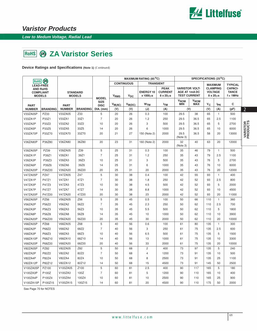
Device Ratings and Specifications (Note 1) (Continued)
V33ZA05 5Z33 20 26 0.3 100 29.5 38 65 1 500
V33ZA1 733Z1 20 26 1.2 250 29.5 36.5 65 2.5 1100
V33ZA2 1033Z2 20 26 3 500 29.5 36.5 65 5 2700
V33ZA5 1433Z5 20 26 6 1000 29.5 36.5 65 10 6000
V33ZA70 2033Z70 21 27 150 (Note 2) 2000 29.5 (Note 3)
36.5 58 20 13000
V36ZA80 2036Z80 23 31 160 (Note 2) 2000 32(Note 3)
40 63 20 12000
V39ZA05 5 Z39 25 31 0.3 100 35 46 79 1 500
V39ZA1 7 39Z1 25 31 1.2 250 35 43 79 2.5 1100
V39ZA3 10 39Z3 25 31 3 500 35 43 76 5 2700
V39ZA6 14 39Z6 25 31 6 1000 35 43 76 10 6000
V39ZA20 2039Z20 25 31 20 2000 35 43 76 20 12000
V47ZA05 5Z47 30 38 0.4 100 42 55 93 1 400
V47ZA1 747Z1 30 38 1.8 250 42 52 93 2.5 800
V47ZA3 1047Z3 30 38 4.5 500 42 52 93 5 2000
V47ZA7 1447Z7 30 38 8.8 1000 42 52 93 10 4500
V47ZA20 2047Z20 30 38 23 2000 42 52 93 20 11000
V56ZA05 5Z56 35 45 0.5 100 50 66 110 1 360
V56ZA2 756Z2 35 45 2.3 250 50 62 110 2.5 700
V56ZA3 1056Z3 35 45 5.5 500 50 62 110 5 1800
V56ZA8 1456Z8 35 45 10 1000 50 62 110 10 3900
V56ZA20 2056Z20 35 45 30 2000 50 62 110 20 10000
V68ZA05 5Z68 40 56 0.6 100 61 80 135 1 300
V68ZA2 768Z2 40 56 3 250 61 75 135 2.5 600
V68ZA3 1068Z3 40 56 6.5 500 61 75 135 5 1500
V68ZA10 1468Z10 40 56 13 1000 61 75 135 10 3300
V68ZA20 2068Z20 40 56 33 2000 61 75 135 20 10000
V82ZA05 5Z82 50 68 2 400 73 97 135 5 240
V82ZA2 782Z2 50 68 4 1200 73 91 135 10 500
V82ZA4 1082Z4 50 68 8 2500 73 91 135 25 1100
V82ZA12 1482Z12 50 68 15 4500 73 91 145 50 2500
V100ZA05 5Z100 60 81 2.5 400 90 117 165 5 180
V100ZA3 7100Z 60 81 5 1200 90 110 165 10 400
V100ZA4 10100Z4 60 81 10 2500 90 110 165 25 900
V100ZA15 14100Z15 60 81 20 4500 90 110 175 50 2000
PARTNUMBER
MODEL SIZEDISC
DIA. (mm)BRANDING
MAXIMUM RATING (85 oC) SPECIFICATIONS (25oC)
CONTINUOUS TRANSIENT
VARISTOR VOLT-AGE AT 1mA DC TEST CURRENT
MAXIMUM CLAMPING VOLTAGE8 x 20µs
TYPICALCAPACI-TANCE
f = 1MHzVRMS VDC
ENERGY 10 x 1000µs
PEAK CURRENT 8 x 20µs
VM(AC) VM(DC) WTM ITM
VNOM MIN
VNOM MAX VC IPK C
(V) (V) (J) (A) (V) (V) (A) (pF)
V33ZA05P PZ33
V33ZA1P P33Z1
V33ZA2P P33Z2
V33ZA5P P33Z5
V33ZA70P P33Z70
V36ZA80P P36Z80
V39ZA05P PZ39
V39ZA1P P39Z1
V39ZA3P P39Z3
V39ZA6P P39Z6
V39ZA20P P39Z20
V47ZA05P PZ47
V47ZA1P P47Z1
V47ZA3P P47Z3
V47ZA7P P47Z7
V47ZA20P P47Z20
V56ZA05P PZ56
V56ZA2P P56Z2
V56ZA3P P56Z3
V56ZA8P P56Z8
V56ZA20P P56Z20
V68ZA05P PZ68
V68ZA2P P68Z2
V68ZA3P P68Z3
V68ZA10P P68Z10
V68ZA20P P68Z20
V82ZA05P PZ82
V82ZA2P P82Z2
V82ZA4P P82Z4
V82ZA12P P82Z12
V100ZA05P PZ100
V100ZA3P P100Z
V100ZA4P P100Z4
V100ZA15P P100Z15
PARTNUMBER BRANDING
LEAD-FREEAND RoHS
COMPLIANTMODELS
STANDARDMODELS
PbRoHS
See Page 70 for NOTES
PbRoHS

70w w w. l i t t e l f u s e . c o m
Varistor Products
ZA Varistor Series
Low to Medum Voltage, Radial Lead
Device Ratings and Specifications (Note1) (Continued)
V120ZA05 5Z120 75 102 3 400 108 138 205 5 140
V120ZA1 7120Z 75 102 6 1200 108 132 205 10 300
V120ZA4 10120Z4 75 102 12 2500 108 132 200 25 750
V120ZA6 14120Z6 75 102 22 4500 108 132 210 50 1700
V120ZA20 20120Z20 75 102 33 6500 108 132 210 100 1500
V150ZA05 5Z150 92 127 4 400 135 173 250 5 120
V150ZA1 7Z051 95 127 8 1200 135 165 250 10 250
V150ZA4 10150Z4 95 127 15 2500 135 165 250 25 600
V150ZA8 14150Z8 95 127 20 4500 135 165 250 50 1400
V150ZA20 20150Z20 95 127 45 6500 135 165 250 100 1000
V180ZA05 5Z180 110 153 5 400 162 207 295 5 100
V180ZA1 7180Z 115 153 10 1200 162 198 300 10 200
V180ZA5 10180Z5 115 153 18 2500 162 198 300 25 500
V180ZA10 14180Z10 115 153 35 4500 162 198 300 50 1100
V180ZA20 20180Z20 115 153 52 6500 162 198 300 100 2400
V205ZA05 5Z205 130 170 5.5 400 184 226 340 5 100
V220ZA05 5Z220 140 180 6 400 198 253 360 5 90
V240ZA05 5Z240 150 200 7 400 216 264 395 5 80
V270ZA05 5Z270 175 225 7.5 400 243 311 455 5 70
V330ZA05 5Z330 210 275 9 400 297 380 540 5 60
V360ZA05 5Z360 230 300 9.5 400 324 396 595 5 55
V390ZA05 5Z390 250 330 10 400 351 449 650 5 50
V430ZA05 5Z430 275 369 11 400 387 495 710 5 45
V470ZA05 5Z470 300 385 12 400 420 517 775 5 35
V620ZA05 5Z620 385 505 13 400 558 682 1025 5 33
V680ZA05 5Z680 420 560 14 400 610 748 1120 5 32
V715ZA05 5Z715 440 585 15.5 400 643 787 1180 5 31
V750ZA05 5Z750 460 615 17 400 675 825 1240 5 30
NOTES:
1. Average power dissipation of transients not to exceed 0.2W, 0.25W, 0.4W, 0.6W or 1W for model sizes 5mm, 7mm, 10mm, 14mm and 20mm, respectively.
2. Energy rating for impulse duration of 30ms minimum to one half of peak current (auto load dump).
3. 10mA DC test current.
4. Also rated to withstand 24V for 5 minutes.
5. Higher voltages available, contact Littelfuse.
† Recognized to UL1449, “Transient Voltage Surge Suppressors” File #E75961.
PARTNUMBER
MODEL SIZEDISC
DIA. (mm)BRANDING
MAXIMUM RATING (85oC) SPECIFICATIONS (25oC)
CONTINUOUS TRANSIENT
VARISTOR VOLT-AGE AT 1mA DC TEST CURRENT
MAXIMUM CLAMPING VOLTAGE8 x 20µs
TYPICALCAPACI-TANCE
f = 1MHzVRMS VDC
ENERGY 10 x 1000µs
PEAK CURRENT 8 x 20µs
VM(AC) VM(DC) WTM ITM
VNOM MIN
VNOM MAX VC IPK C
(V) (V) (J) (A) (V) (V) (A) (pF)
V120ZA05P PZ120
V120ZA1P P120Z
V120ZA4P P120Z4
V120ZA6P P120Z6
V120ZA20P P120Z20
V150ZA05P PZ150
V150ZA1P PZ051
V150ZA4P P150Z4
† V150ZA8P P150Z8
V150ZA20P P150Z20
V180ZA05P PZ180
V180ZA1P P180Z
V180ZA5P P180Z5
V180ZA10P P180Z10
V180ZA20P P180Z20
V205ZA05P PZ205
† V220ZA05P PZ220
† V240ZA05P PZ240
† V270ZA05P PZ270
† V330ZA05P PZ330
† V360ZA05P PZ360
† V390ZA05P PZ390
† V430ZA05P PZ430
† V470ZA05P PZ470
† V620ZA05P PZ620
† V680ZA05P PZ680
V715ZA05P PZ715
V750ZA05P PZ750
PARTNUMBER BRANDING
LEAD-FREEAND RoHS
COMPLIANTMODELS
STANDARDMODELS
PbRoHS
PbRoHS

71w w w. l i t t e l f u s e . c o m
2
VAR
ISTO
RP
RO
DU
CT
S
Varistor ProductsLow to Medum Voltage, Radial Lead
ZA Varistor Series
Power Dissipation RatingsShould transients occur in rapid succession, the average power dissipationrequired is simply the energy (watt-seconds) per pulse times the numberof pulses per second. The power so developed must be within the specifications shown on the Device Ratings and Specifications table forthe specific device. Furthermore, the operating values need to be deratedat high temperatures as shown in Figure 1. Because varistors can only dissipate a relatively small amount of average power they are, therefore,not suitable for repetitive applications that involve substantial amounts ofaverage power dissipation.
FIGURE 1. CURRENT, ENERGY AND POWER DERATING CURVE
100
90
80
70
60
50
40
30
20
10
0-55 50 60 70 80 90 100 110 120 130 140 150
AMBIENT TEMPERATURE ( oC)
PE
RC
EN
T O
F R
ATE
D V
AL
UE
FIGURE 2. PEAK PULSE CURRENT TEST WAVEFORM
100
90
50
10
O1 T
T1T2
TIME
PE
RC
EN
T O
F P
EA
K V
AL
UE
O1 = Virtual Origin of WaveT = Time From 10% to 90% of Peak
T1 = Virtual Front time = 1.25 • tT2 = Virtual Time to Half Value (Impulse Duration)
Example: For an 8/20µs Current Waveform:8µs = T1 = Virtual Front Time
20µs = T2 = Virtual Time to Half Value
FIGURE 3. CLAMPING VOLTAGE FOR V8ZA05(P) - V68ZA05(P)
600500400300
200
100908070605040
30
20
MA
XIM
UM
PE
AK
VO
LTS
(V
)
PEAK AMPERES (A)10-2 10-1 100 101 102 103
MAX CLAMPING VOLTAGEMODEL SIZE 5mm8 TO 68VN(DC) RATINGTA = -55oC TO 85oC
10
V68ZA05(P)V56ZA05(P)V47ZA05(P)V39ZA05(P)V33ZA05(P)V27ZA05(P)V22ZA05(P)V18ZA05(P)V12ZA05(P)
V8ZA05(P)
10-3
FIGURE 4. CLAMPING VOLTAGE FOR V82ZA05(P) - V33ZA05(P)
2000
1000
500
200MA
XIM
UM
PE
AK
VO
LTS
(V
)
PEAK AMPERES (A)
0.01 0.1 1 10 100 1000100
0.0010.0001
V100ZA05(P)
V82ZA05(P)
MAX CLAMPING VOLTAGEMODEL SIZE 5mm82 TO 330VN(DC) RATINGTA = -55oC TO 85oC
V330ZA05(P)V270ZA05(P)V240ZA05(P)V220ZA05(P)V205ZA05(P)V180ZA05(P)V150ZA05(P)V120ZA05(P)
Transient V-I Characteristics Curves
PbRoHS

72w w w. l i t t e l f u s e . c o m
Varistor Products
ZA Varistor Series
Low to Medum Voltage, Radial Lead
Transient V-I Characteristics Curves (Continued)
FIGURE 5. CLAMPING VOLTAGE FOR V360ZA05(P) - V750ZA05(P) FIGURE 6. CLAMPING VOLTAGE FOR V8ZA1(P) - V68ZA2(P)
FIGURE 7. CLAMPING VOLTAGE FOR V82ZA2(P) - V180ZA1(P) FIGURE 8. CLAMPING VOLTAGE FOR V8ZA2(P) - V68ZA3(P)
FIGURE 9. CLAMPING VOLTAGE FOR V82ZA4(P) - V180ZA5(P) FIGURE 10. CLAMPING VOLTAGE FOR V18ZA3(P) - V68ZA10(P)
3000
2000
1000
500
MA
XIM
UM
PE
AK
VO
LTS
(V
)
PEAK AMPERES (A)
0.01 0.1 1 10 100 10000.0010.0001
V750ZA05(P)V715ZA05(P)V680ZA05(P)V620ZA05(P)V470ZA05(P)V430ZA05(P)V390ZA05(P)V360ZA05(P)
MAX CLAMPING VOLTAGEMODEL SIZE 5mm360 TO 750VN(DC) RATINGTA = -55oC TO 85oC
500400
300
200
100908070605040
30
20
10M
AX
IMU
M P
EA
K V
OLT
S (
V)
10-3 10-2 10-1 100 101 102 103
MAXIMUM CLAMPING VOLTAGE
8 TO 68VN(DC) RATINGTA = -55oC TO 85oC
PEAK AMPERES (A)
V68ZA2(P)V56ZA2(P)V47ZA1(P)V39ZA1(P)V33ZA1(P)V27ZA1(P)V22ZA1(P)
V12ZA1(P)V18ZA1(P)
V8ZA1(P)
MODEL SIZE 7mm
MA
XIM
UM
PE
AK
VO
LTS
(V
)
PEAK AMPERES (A)10-2 10-1 100 101 102 10310-3
MAXIMUM CLAMPING VOLTAGEMODEL SIZE 7mm82 TO 180VN(DC) RATINGTA = -55oC TO 85oC
4,000
3,000
2,000
1,000900800700600500400
300
200
100104
V180ZA1(P)V150ZA1(P)
V120ZA1(P)V100ZA3(P)
V82ZA2(P)
500400
300
200
100908070605040
30
20
10
MA
XIM
UM
PE
AK
VO
LTS
(V
)
10-3 10-2 10-1 100 101 102 103
PEAK AMPERES (A)
V68ZA3(P)V56ZA3(P)V47ZA3(P)V39ZA3(P)V33ZA2(P)V27ZA2(P)V22ZA2(P)V18ZA2(P)
V8ZA2(P)
V12ZA2(P)
MAXIMUM CLAMPING VOLTAGEMODEL SIZE 10mm8 TO 68VN(DC) RATINGTA = -55oC TO 85oC
MA
XIM
UM
PE
AK
VO
LTS
(V
)
PEAK AMPERES (A)10-2 10-1 100 101 102 10310-3
MAXIMUM CLAMPING VOLTAGEMODEL SIZE 10mm82 TO 180VN(DC) RATINGTA = -55oC TO 85oC
4,000
3,000
2,000
1,000900800700600500400
300
200
100104
V180ZA5(P)V150ZA4(P)
V120ZA4(P)V100ZA4(P)
V82ZA4(P)
600500400
300
200
100908070605040
30
2010-3 10-2 10-1 100 101 102 103
PEAK AMPERES (A)
MA
XIM
UM
PE
AK
VO
LTS
(V
)
V68ZA10(P)V56ZA8(P)V47ZA7(P)V39ZA6(P)V33ZA5(P)V27ZA4(P)V22ZA3(P)V18ZA3(P)
MAXIMUM CLAMPING VOLTAGE
18 TO 68VN(DC) RATINGTA = -55oC TO 85oC
MODEL SIZE 14mm
PbRoHS

73w w w. l i t t e l f u s e . c o m
2
VAR
ISTO
RP
RO
DU
CT
S
Varistor ProductsLow to Medum Voltage, Radial Lead
ZA Varistor Series
Transient V-I Characteristics Curves (Continued)
FIGURE 11. CLAMPING VOLTAGE FOR V82ZA12(P) - V180ZA10(P) FIGURE 12. CLAMPING VOLTAGE FOR V18ZA40(P) - V36ZA80(P)
FIGURE 13. CLAMPING VOLTAGE FOR V39ZA20(P) - V180ZA20(P)
MA
XIM
UM
PE
AK
VO
LTS
(V
)
PEAK AMPERES (A)10-2 10-1 100 101 102 10310-3
MAXIMUM CLAMPING VOLTAGEMODEL SIZE 14mm82 TO 180VN(DC) RATINGTA = -55oC TO 85oC
4,000
3,000
2,000
1,000900800700600
500400
300
200
100104
V180ZA10(P)V150ZA8(P)
V120ZA6(P)V100ZA15(P)
V82ZA12(P)
300
200
10090807060
50
40
30
20M
AX
IMU
M P
EA
K V
OLT
S (
V)
PEAK AMPERES (A)10-2 10-1 100 101 102 10310-3 104
MAXIMUM CLAMPING VOLTAGEMODEL SIZE 20mm18 TO 36VN(DC) RATINGTA = -55oC TO 85oC
V36ZA80(P)V33ZA70(P)
V27ZA60(P)V24ZA50(P)
V18ZA40P(P)
10-3 10-2 10-1 100 101 102 104103
1,000
500
300
200
30
PEAK AMPERES (A)
MA
XIM
UM
PE
AK
VO
LTS
(V
)
V56ZA20(P)V47ZA20(P)
V39ZA20(P)
MAXIMUM CLAMPING VOLTAGEMODEL SIZE 20mm
TA = -55oC TO 85oC39 TO 180VM(AC) RATING V180ZA20(P)
V150ZA20(P)V120ZA20(P)
100
50
V68ZA20(P)
Pulse Rating Curves
FIGURE 14. SURGE CURRENT RATING CURVES FOR V8ZA05(P) FIGURE 15. SURGE CURRENT RATING CURVES FOR
50
20
10
5
2
1
0.5
0.2
0.1
SU
RG
E C
UR
RE
NT
(A
)
20 100 1,000 10,000IMPULSE DURATION (µs)
1
10
102
2
103
INDEFINITE
104105
106
MODEL SIZE 5mmV8ZA05(P)
100
50
20
10
2
1
0.5
0.2
0.1
SU
RG
E C
UR
RE
NT
(A
)
20 100 1,000 10,000IMPULSE DURATION (µs)
INDEFINITE
104105
106
MODEL SIZE 5mmV12ZA05(P) - V68ZA05(P)
110
102
2
103
PbRoHS
74w w w. l i t t e l f u s e . c o m
Varistor Products
ZA Varistor Series
Low to Medum Voltage, Radial Lead
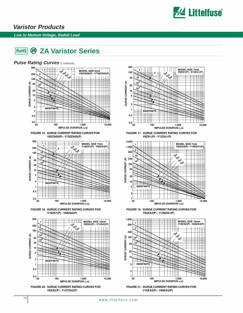
Pulse Rating Curves (Continued)
FIGURE 16. SURGE CURRENT RATING CURVES FOR V82ZA05(P) - V750ZA05(P)
FIGURE 17. SURGE CURRENT RATING CURVES FORV8ZA1(P) - V12ZA1(P)
FIGURE 18. SURGE CURRENT RATING CURVES FOR V18ZA1(P) - V68ZA2(P)
FIGURE 19. SURGE CURRENT RATING CURVES FOR V82ZA2(P) - V180ZA1(P)
FIGURE 20. SURGE CURRENT RATING CURVES FOR V8ZA2(P) - V127ZA2(P)
FIGURE 21. SURGE CURRENT RATING CURVES FOR V18ZA2(P) - V68ZA3(P)
50
20
10
5
2
1
0.5
0.2
SU
RG
E C
UR
RE
NT
(A
)
20 100 1,000 10,000IMPULSE DURATION (µs)
1
10
102
2103
INDEFINITE
104105
106
MODEL SIZE 5mmV82ZA05(P) - V750ZA05(P)
500
200
100
20 100 1,000 10,000IMPULSE DURATION (µs)
SU
RG
E C
UR
RE
NT
(A
)
1
10
102
2
103
INDEFINITE
104105
106
200
100
50
20
10
5
2
1
0.5
0.2
MODEL SIZE 7mmV8ZA1(P) - V12ZA1(P)
20 100 1,000 10,000IMPULSE DURATION (µs)
SU
RG
E C
UR
RE
NT
(A
)
1
10
102
2
103
INDEFINITE
500
200
100
50
20
10
2
1
0.5
0.2
104105
106
5
MODEL SIZE 7mmV18ZA1(P) - V68ZA2(P)
2,000
1,000
200
100
50
20
10
5
1
2
500
20 100 1,000 10,000IMPULSE DURATION (µs)
SU
RG
E C
UR
RE
NT
(A
)
1
2
10
102104
105
106
103
INDEFINITE
MODEL SIZE 7mmV82ZA2(P) - V180ZA1(P)
20 100 1,000 10,000IMPULSE DURATION (µs)
SU
RG
E C
UR
RE
NT
(A
)
1
10
102
2
103
INDEFINITE
500
200
100
50
20
10
2
1
0.5
0.2
104105
106
5
MODEL SIZE 10mmV8ZA2(P) - V12ZA2(P)
1,000
500
100
50
20
10
5
1
2
200
20
SU
RG
E C
UR
RE
NT
(A
)
1
2
105
106
104
INDEFINITE
MODEL SIZE 10mmV18ZA2(P) - V68ZA3(P)
100 1,000 10,000IMPULSE DURATION (µs)
102
103
PbRoHS

75w w w. l i t t e l f u s e . c o m
2
VAR
ISTO
RP
RO
DU
CT
S
Varistor ProductsLow to Medum Voltage, Radial Lead
ZA Varistor Series
Pulse Rating Curves (Continued)
FIGURE 22. SURGE CURRENT RATING CURVES FOR V82ZA4(P) - V180ZA5(P)
5,000
2,000
1,000
500
200
100
50
20
10
5
220 100 1,000 10,000
IMPULSE DURATION (µs)
SU
RG
E C
UR
RE
NT
(A
)
1
10
102
2
103
INDEFINITE
104105
106
MODEL SIZE 10mmV82ZA4(P) - V180ZA5(P)
FIGURE 23. SURGE CURRENT RATING CURVES FOR V18ZA3(P) - V68ZA10(P)
200
100
50
20
10
5
1
2
20 100 1,000 10,000IMPULSE DURATION (µs)
SU
RG
E C
UR
RE
NT
(A
)
12
10
102
104
105
106
103
INDEFINITE
1,000
500MODEL SIZE 14mmV18ZA3(P) - V68ZA10(P)
PbRoHS

76w w w. l i t t e l f u s e . c o m
Varistor Products
ZA Varistor Series
Low to Medum Voltage, Radial Lead
NOTE: If pulse ratings are exceeded, a shift of VN(DC)(at specified current) of more then ±10% could result. This type of shift, which normally results in a decrease of VN(DC),may result in the device not meeting the original published specifications, but does not prevent the device from continuing to function, and to provide ample protection.
Pulse Rating Curves (Continued)
FIGURE 24. SURGE CURRENT RATING CURVES FOR V82ZA12(P) - V180ZA10(P)
FIGURE 25. SURGE CURRENT RATING CURRENT FOR V18ZA40(P) - V68ZA20(P)
FIGURE 26. SURGE CURRENT RATING CURVES FOR V120ZA20(P) - V180ZA20(P)
5,000
2,000
200
100
50
20
10
5
2
500
20 100 1,000 10,000IMPULSE DURATION (µs)
SU
RG
E C
UR
RE
NT
(A
)
12
10
104
105
106
103
INDEFINITE
1,000 102
MODEL SIZE 14mmV82ZA12(P) - V180ZA10(P)
2,000
200
100
50
20
10
5
2
500
20 100 1,000 10,000IMPULSE DURATION (µs)
SU
RG
E C
UR
RE
NT
(A
)
12
101,000
102
103
104
105
106
INDEFINITE
MODEL SIZE 20mmV18ZA40(P) - V68ZA20(P)
10,0001,00010020
IMPULSE DURATION (µs)
SU
RG
E C
UR
RE
NT
(A
)
5,00010,000
2,000
500
100
20
10
2
1,000
200
50
1
5
12
10
102
103
104
105
106
INDEFINITE
MODEL SIZE 20mmV120ZA20(P) - V180ZA20(P)
PbRoHS

77w w w. l i t t e l f u s e . c o m
2
VAR
ISTO
RP
RO
DU
CT
S
Varistor Products
ZA Varistor Series
Low to Medum Voltage, Radial Lead
Tape and Reel Specifications
Crimped Leads "ZT" Crimped Leads "ZT"
Straight Leads "ZS"Straight Leads "ZS"
Under-crimped Leads "ZU"
P1P0
E
DPDH DH
W1
W
F t
W2W0
P
DP
C
∆bH0
∆D0
H1SEATING PLANE
P2
P1
P1
W0
E
DPDH DH
W1
W
F t
W2
P
DP
C
∆bH0
∆D0
H1SEATING PLANE
P2
P0
DH
E
DHDP
W1
W
F t
W2
P
DP
∆bH
∆D0
H1
P1
P2
W0
P1P0
P2
DH
E
DHDP
W1
W
F t
W2W0
P
DP
∆bH
∆D0
H1
U
P1P0
P2
DH
E
DHDP
W1
W
F t
W2W0
P
DP
∆bHo
∆D0
H1
Under-crimped Leads "ZU"
P0
U
DH
E
DHDP
W1
W
F t
W2
P
DP
∆bHo
∆D0
H1
P2
W0
P1
5 and 7mm Devices 10, 14 and 20mm Devices
PbRoHS

78w w w. l i t t e l f u s e . c o m
Varistor Products
Tape and Reel Data• Conforms to ANSI and EIA specifications
• Can be supplied to IEC Publication 286-2
• Radial devices on tape are supplied withcrimped leads, straight leads, or under-crimped leads
• 5mm parts are available on tape and reel upto 385 VAC only
NOTE: Leads are offset by Dim e1
SYMBOL PARAMETER
MODEL SIZE
5mm 7mm 10mm 14mm 20mm
P Pitch of Component 12.7 ± 1.0 12.7 ± 1.0 25.4 ± 1.0 25.4 ± 1.0 25.4 ± 1.0
P0 Feed Hole Pitch 12.7 ± 0.2 12.7 ± 0.2 12.7 ± 0.2 12.7 ± 0.2 12.7 ± 0.2
P1 Feed Hole Center to Pitch 3.85 ± 0.7 3.85 ± 0.7 8.85 ± 0.7 8.85 ± ± 0.7 8.85 0.7
P2 Hole Center to Component Center 6.35 ± 1.0 6.35 ± 1.0 12.7 ± 0.7 12.7 ± 0.7 12.7 ± 0.7
F Lead to Lead Distance 5.0 ± 1.0 5.0 ± 1.0 7.5 ± 1.0 7.5 ± 1.0 7.5 ± 1.0
h Component Alignment 2.0 Max 2.0 Max 2.0 Max 2.0 Max 2.0 Max
W Tape Width 18.0 + 1.018.0 - 0.5
18.0 + 1.018.0 - 0.5
18.0 + 1.018.0 - 0.5
18.0 + 1.018.0 - 0.5
18.0 + 1.018.0 - 0.5
W0 Hold Down Tape Width ±12.0 0.3 ±12.0 0.3 ±12.0 0.3 ±12.0 0.3 ±12.0 0.3
W1 Hole Position 9.0 + 0.759.0 - 0.50
9.0 + 0.759.0 - 0.50
9.0 + 0.759.0 - 0.50
9.0 + 0.759.0 - 0.50
9.0 + 0.759.0 - 0.50
W2 Hold Down Tape Position 0.5 Max 0.5 Max 0.5 Max 0.5 Max 0.5 Max
H Height from Tape Center toComponent Base
18.0 + 2.018.0 - 0.0
18.0 + 2.018.0 - 0.0
18.0 + 2.018.0 - 0.0
18.0 + 2.018.0 - 0.0
18.0 + 2.018.0 - 0.0
H0 Seating Plane Height 16.0 ± 0.5 16.0 ± 0.5 16.0 ± 0.5 16.0 ± 0.5 16.0 ± 0.5
H1 Component Height 29.0 Max 32.0 Max 36.0 Max 40.0 Max 46.5 Max
D0 Feed Hole Diameter 4.0 ± 0.2 4.0 ± 0.2 4.0 ± 0.2 4.0 ± 0.2 4.0 ± 0.2
t Total Tape Thickness 0.7 ± 0.2 0.7 ± 0.2 0.7 ± 0.2 0.7 ± 0.2 0.7 ± 0.2
U Under-crimp Width 8.0 Max
p Component Alignment 3o Max 3o Max 3o Max 3o Max 3o Max
NOTE: Dimensions are in mm.
8.0 Max 8.0 Max 8.0 Max 8.0 Max
Low to Medum Voltage, Radial Lead
ZA Varistor SeriesPbRoHS

79w w w. l i t t e l f u s e . c o m
2
VAR
ISTO
RP
RO
DU
CT
S
Varistor ProductsLow to Medum Voltage, Radial Lead
ZA Varistor Series
Mechanical Dimensions
Tape and Reel Ordering InformationCrimped leads are standard on ZA types supplied in tape and reel andare denoted by the model letter “T”. Model letter “S” denotes straightleads and letter “U” denotes special under-crimped leads.
Example:
STANDARD MODEL
CRIMPED LEADS
STRAIGHT LEADS
UNDER-CRIMPED
LEADS
V18ZA3 V18ZT3 V18ZS3 V18ZU3
SHIPPING QUANTITY
SIZE
RMS (MAX)
VOLTAGE
QUANTITY PER REEL
“T” REEL “S” REEL “U” REEL
5mm All 1000 1000 1000
7mm All 1000 1000 1000
10mm All 500 500 500
14mm < 300V 500 500 500
14mm ≥ 300V 500 500 400
20mm < 300V 500 500 500
20mm ≥ 300V 500 500 400
SYM-BOL
VOLTAGE MODEL
VARISTOR MODEL SIZE
5mm 7mm 10mm 14mm 20mm
MIN MAX MIN MAX MIN MAX MIN MAX MIN MAX
A All --
10 (0.394)
--
12 (0.472)
--
16 (0.630)
--
20 (0.787)
--
26.5 (1.043)
øD All --
7 (0.276)
--
9 (0.354)
--
12.5 (0.492)
--
17 (0.669)
--
23 (0.906)
e All 4 (0.157)
6 (0.236)
4 (0.157)
6 (0.236)
6.5 (0.256)
8.5 (0.335)
6.5 (0.256)
8.5 (0.335)
6.5 (0.256)(Note 6)
8.5 (0.335)(Note 6)
e1 V8ZA-V56ZA
1 (0.039)
3 (0.118)
1 (0.039)
3 (0.118)
1 (0.039)
3 (0.118)
1 (0.039)
3 (0.118)
1 (0.039)
3 (0.118)
V68ZA-V100ZA
1.5 (0.059)
3.5 (0.138)
1.5 (0.059)
3.5 (0.138)
1.5 (0.059)
3.5 (0.138)
1.5 (0.059)
3.5 (0.138) (0.059) (0.138)
1.5 3.5
V120ZA-V180ZA
1 (0.039)
3 (0.118)
1 (0.039)
3 (0.118)
1 (0.039)
3 (0.118)
1 (0.038)
3(0.118) (0.038) (0.118)
V205ZA-V750ZA
1.5 (0.059)
3.5 (0.138)
--
--
--
--
--
--
--
--
E V8ZA-V56ZA
--
5 (0.197)
--
5 (0.197)
--
5 (0.197)
--
5 (0.197)
--
5 (0.197)
V68ZA-V100ZA
--
5.6 (0.220)
--
5.6 (0.220)
--
5.6 (0.220)
--
5.6 (0.220)
--
5.6 (0.220)
V120ZA-V180ZA
--
5 (0.197)
--
5 (0.197)
--
5 (0.197)
--
5 (0.197)
--
5 (0.197)
V205ZA-V750ZA
--
5.6 (0.220)
--
--
--
--
--
--
--
--
øb All 0.585 (0.023)
0.685 (0.027)
0.585 (0.023)
0.685 (0.027)
0.76 (0.030)
0.86 (0.034)
0.76 (0.030)
0.86 (0.034)
0.76 (0.030)
0.86 (0.034)
NOTES: Dimensions in millimeters, inches in parentheses.
6. 10mm ALSO AVAILABLE; See Additional Lead Style Options.
7. V24ZA50(P) and V24ZC50(P) only supplied with lead spacing of 6.35mm ± 0.5mm (0.25 ± 0.0196)Dimension e = 5.85 min. Does not apply to T&R parts.
1 3
PbRoHS

80w w w. l i t t e l f u s e . c o m
Varistor Products
ZA Varistor Series
Low to Medum Voltage, Radial Lead
Additional Lead Style OptionsRadial lead types can be supplied with combination preformed crimp andtrimmed leads. This option is supplied to the dimensions shown.
• To order this crimped and trimmed lead style, standard radial typemodel numbers are changed by replacing the model letter “ZA” with“ZC”. This option is supplied in bulk only.
Example:
For crimped leads without trimming and any varitions to the above, contact Littelfuse.
• For 10/±1mm lead spacing on 20mm diameter models only; append stan-dard model numbers by adding “X10”.
Example:
*SEATING PLANE INTERPRETATION PER IEC-717 CRIMPED AND TRIMMED LEAD
STANDARD CATALOGMODEL ORDER AS:
V18ZA3 V18ZC3
VARISTOR
VARISTOR NOMINALVOLTAGE (VNOM)
(One, Two or Three Digits)
SERIES DESIGNATOR/LEAD STYLE DESIGNATOR
ZC = Crimped and ClippedZS = StraightZT = CrimpedZU = Under Crimped
V XXX ZA XX
RELATIVE ENERGY INDICATOR(One or Two Digits)
P: LEAD-FREE AND RoHS COMPLIANT OPTION
P
Other OptionsBase Part #
Ordering InformationZA series Varistors are shipped standard in bulk pack with straight leadsand lead spacing outlined in the package dimensions on page 4-13.Contact your Littelfuse sales representative to discuss the non-standardoptions outlined below.
For Lead-free and RoHS compliant parts add the letter ‘P’ after the basepart number and before any option as shown in the ordering examplebelow.
ex: V8ZA40PX10V150ZA20PX1347
ZA series varistors for Hi-Temperature operating conditions:• Phenolic Coated ZA Series devices are available with improved maxi-
mum operating maximum temperature 125°C.• These devices also have improved temperature cycling performance
capability.• Ratings and Specifications are as per standard ZA Series except Hi-
Pot encapsulation Isolation Voltage Capability = 500V.• To order: add X1347 to part number (e.g. V22ZA3X1347)• These devices are not UL, CSA, VDE or CECC certified.• Contact factory for further details.
SYMBOL
VARISTOR MODEL SIZE
5mm 7mm 10mm 14mm 20mm
MIN MAX MIN MAX MIN MAX MIN MAX MIN MAX
A --
13.0 (0.512)
--
15(0.591)
--
19.5 (0.768)
--
22.5 (0.886)
--
29.0 (1.142)
LTRIM 2.41 (0.095)
4.69 (0.185)
2.41 (0.095)
4.69 (0.185)
2.41 (0.095)
4.69 (0.185)
2.41 (0.095)
4.69 (0.185)
2.41 (0.095)
4.69 (0.185)
NOTE: Dimensions in millimeters, inches in parentheses.
STANDARD CATALOGMODEL ORDER AS:
V18ZA40 V18ZA40X10
PbRoHS