Embed Size (px)
Citation preview
ROLE OF GEOTECHNICAL ENGINEERING IN ASSURING THE INTEGRITY OF BURIED PIPELINE
SYSTEMS
Dharma Wijewickreme1
1University of British Columbia, Vancouver, B.C., Canada
Telephone: 1-604-822-5112; Fax: 1-604-822-6901
E-mail: [email protected]
Abstract
Buried pipeline systems form a major part of global infrastructure that threads the human-made
physical environment, contributing to the health, safety, and welfare of communities. Satisfactory
performance of these pipeline systems, therefore, has become a key factor in assuring a sustainably
built environment since any significant disruption to them often translates into undesirable impacts on
economies or the living conditions of citizens. Geotechnical engineering has a dominant role to play
in ensuring satisfactory performance of buried pipelines. Adequate knowledge of site-specific soil
and groundwater conditions is critical to the design of pipelines, as well as ensuring good predictions
of their field performance. Quantification of anticipated geotechnical hazards and evaluation of their
impacts are other important considerations in assessing the long-term performance of buried
pipelines. The interaction between buried pipes and surrounding soil is complex. Therefore,
approaches ranging from those based on simplified assumptions to sophisticated numerical modeling
techniques need to be employed in solving soil-pipe interaction problems. The overall goal is to
reduce the risk of damage to buried pipelines from geotechnical hazards. A spectrum of options such
as isolation from the hazard, accommodation of the hazard, or mitigation of the hazard using ground
improvement can be considered in this regard.
Keywords: Buried pipelines, pipeline integrity, geotechnical engineering, geotechnical hazards
1. Introduction
Buried pipeline systems form a key part of global lifeline infrastructure that serves as the backbone to
the human-made physical environment that contributes to upholding the health, safety, and welfare of
society. Pipeline systems are commonly used to transport large quantities of fluids between
geographic locations. Compared to ground transportation, they offer a mode of transfer of fluids at
lower cost per unit volume and at higher capacity; the transportation of water, sanitary waste, oil, gas,
and hot water (for district heating) are some examples in this regard. Most pipelines are located
along over-land alignments although there are some major pipelines that are located under the sea
primarily to transport petroleum products.
In spite of the advantages in terms of efficiently serving the society, the risk of damage to pipelines is
a key consideration from a sustainability point of view. Any significant disruption to the performance
of pipeline systems often translates into undesirable impacts on regional businesses, economies, the
living conditions of citizens, along with likely adverse effects on the environment (e.g., risk of harm
to the environment from loss of integrity in oil pipelines). Based on available data from the U. S.
Pipeline and Hazardous Materials Safety Administration (PMHSA 2011), the average damage costs
arising from significant pipeline damage incidents over the past 10 years have been in excess of
$400M/year. Pipeline damage statistics from Canada, Europe, and the United States indicate that
about one-eighth of all pipeline damage incidents over the last 30 years have been due to geotechnical
hazards. It has been noted that pipeline failures induced due to ground movements would typically
lead to damage costs more than double those arising from other hazards.
In addition to the loads from the transported content, it is critical that buried pipelines accommodate
external loads that are transmitted through the surrounding soils (generally referred to as “soil loads”).
The soil loads on pipelines can be wide ranging, and they include one or a combination of the
following loadings that arise during different phases over the lifespan of a pipeline system: (i) pipeline
installation; (ii) general operation; and (iii) extreme situations (e.g., landslides, earthquake-induced
ground movements, etc.). Therefore, geotechnical engineering, the sub-discipline of civil engineering
that addresses the concerns related to the use of earth as an engineering material, has a critical role to
play in the design, construction, and satisfactory operation of pipelines.
This paper is aimed at presenting geotechnical considerations associated with pipeline engineering
with particular reference to the above phases. Pipeline materials and installation methods are briefly
discussed at the outset and the approaches available to identify and quantify geotechnical hazards on
buried pipelines, and engineering solutions to mitigate geotechnical hazards are then discussed.
2. Pipeline materials and installation methods
2.1 Pipeline materials
The type of pipeline material selected is dependent on many factors. When transporting content under
high pressure, the expected maximum internal pressure mostly governs the pipe design. Pipe
materials with good stress crack resistance, low permeation, high impact resistance, and satisfactory
UV performance are often sought by the designers.
Welded large diameter steel pipes are often used in industry applications for conveying pressurized
water, oil, and natural gas. Usually, the exterior of steel pipes are specially coated to protect against
corrosion and abrasion. Due to the high strength and ductile nature, steel pipes are equally good in
many applications involving rough terrains or regions where ground movements are expected.
Polymeric plastic piping (e.g., PVC - Polyvinyl chloride, PE - Polyethylene, PB - Polybutylene, and
PP - Polypropylene) is also used for industrial applications such as sewer and municipal and industrial
waste, natural gas distribution, potable water transportation or as subsoil field drains. The plastic pipes
are considered advantageous because of their lower material, installation, and maintenance costs and
their high corrosion resistance and extensibility.
The pipes used for district heating have a composite cross-section since they are typically pre-
insulated, bonded DH pipes where three different materials are combined in the manufacturing
process. These materials include: steel pipes for the supply of hot water, surrounding insulation foam
made of polyurethane, and an outer pipe coating made of polyethylene. Consequently, the interface
between the pipe and the surrounding soil is polyethylene (Weidlich and Wijewickreme 2012).
2. 2 Pipeline installation methods
Installation of the pipelines below the ground surface has been found to be very attractive since it
provides a convenient mode of supporting and protecting the pipelines. The determination of critical
loads for engineering design of buried pipes requires consideration of the internal pressure of
transported fluid and/or external loads from the soil surrounding. For example, the design of high
pressure lines under operating conditions is mostly governed by the internal content pressure (e.g., oil
and gas pipelines) as the external soil loads are comparatively small under typical operating
conditions. In comparison, for pipelines with relatively low internal pressure (e.g., water and sewer
pipelines), the soil overburden loads can be a significant operating consideration.
Most pipelines are buried at shallow depths below the ground (less than 1.5 m) for the ease of
installation and access during maintenance or repair. The open-cut (or cut-and-cover) is the most
common method of pipe installation in such shallow burial depths, in which a trench is excavated
from the ground surface, and then pipes are placed to meet a certain gradient and alignment (Figure
1). In the presence of space constraints, earth support systems of trenches and groundwater
dewatering may be required. The trench is backfilled with select material types or with the native soil.
When pipeline are below roadways, the backfill often requires to be compacted to a specified density.
Buried pipelines need to be located at greater depths in situations such as below-water river crossings
(see Figure 2), mountain passes, etc., and trenchless techniques are adopted in such installations
(Chehab and Moore 2008; Moore 2010). Some of the technologies for trenchless installations
include: (a) horizontal auger boring; (b) horizontal directional drilling (HDD); (c) micro-tunneling;
(d) pipe ramming; (e) moling; and (f) pipe bursting. Depending on the available or chosen alignment,

trenchless pipeline installation processes can be economically and technically demanding, however,
the methods are becoming increasingly popular due to the advantages in protecting the environment
and impacting developed areas. The North American Society for Trenchless Technology (NASTT
2012) serves as one of the leading engineering societies and trade associations promoting and
educating with respect to the renewal and installation of buried infrastructure using trenchless
technology and the practical, social and environmental benefits thereof.
Figure 1: Typical open cut installation of buried pipelines.
Figure 2: Example of a below-water pipeline river crossing; plan and profile of design pipeline
alignment – FortisBC Fraser River Crossing Project, Vancouver, British Columbia, Canada.
3. General geotechnical engineering considerations
Detailed understanding of subsurface soil and groundwater conditions along a given pipeline
alignment through adequate geotechnical investigation is one of the keys to good design and
construction of pipelines to meet the performance requirements. This is particularly important for
trenchless techniques where special construction risks and significant challenges during pipe
installation may arise due to potentially unforeseen soil and groundwater conditions.
Geotechnical investigations to determine site-specific soil and groundwater conditions could range
from sampled test pits to other in-situ testing and geophysical profiling techniques. The extent of
exploratory test holes (in terms of number and depth) and the investigation methodology should be
based on the general knowledge of the regional geology, length/depth of the subject pipeline
alignment, and the level of sophistication of the installation technique. Relatively deep drilled
geotechnical test holes are typically required in cases with trenchless installations with deep
alignments. While drilled test holes should be located close to the pipeline alignment, it is preferable
that they are performed with at least a 10-m offset from the proposed alignment to minimize the risk
of drill fluid escaping during trenchless pipeline installation work. If the initial findings indicate
anomalies, discontinuity in the strata, the presence of rock or large concentrations of gravel, it is
advisable to make additional borings to better define the strata. At below-water channel crossings,
serious consideration should be given to carrying out adequate investigation within the channel
section.
Laboratory sieve analyses and index testing are generally carried out on selected samples to classify
the soils and to prepare detailed borehole logs, as appropriate. Information on the shear strength of
fine-grained soils may be obtained using vane shear testing, unconfined laboratory compressive
strength testing, etc. If rock is encountered, the type of rock and mineralogy, the Rock Quality
Designation (RQD), the relative hardness, and the unconfined compressive strength should generally
be determined.
4. Soil loads on pipelines during construction and general operational conditions
Forces imparted by soils on a buried pipe is dependent on a number of factors: (i) the type and
mechanical properties of the soil; (ii) the type and mechanical properties of the pipe material and pipe
geometry; and (iii) pipe-soil interaction which is largely driven by the relative stiffness and strength of
pipe materials in relation to the soil surrounding.
There have been many methods developed to determine the pipe performance under static loading.
They range from closed-form solutions mainly developed assuming elastic pipe/soil material
conditions; empirical and semi-empirical approaches; and numerical analyses methods based on two-
dimensional and three-dimensional finite-element and finite-difference analyses supported by physical
field and laboratory testing.

4.1 Static loads
Static soil loads on pipes buried in soils are based on the use of methods developed for determining
geostatic stresses under free-field conditions (i.e., stress conditions prevalent without pipe). The
vertical stress and horizontal stress, therefore, are expressed using the following formulae:
v H (1)
h vK (2)
where: v = vertical effective stress at a given depth;
h = horizontal effective stress at that depth; = average effective unit weight of soil above pipe; H = depth from ground surface to the point of
interest; K = coefficient of lateral earth pressure (Note: under geostatic “at rest” conditions, 0K K
= coefficient of lateral earth pressure at rest). While the loads only from effective soil stresses are
considered in the subsequent discussions, groundwater pressures should be accounted as appropriate.
In the presence of groundwater, additional pore pressure could develop due to soil shear-induced
volume change tendencies.
The weight of soil within the rectangular prism of soil having a width equal to the pipe diameter ( D )
and a height equal to the depth of soil (h) above the crown level of the pipe (termed "prism load", Wp)
is often used for computation of static soil stresses on pipes (see Figure 3). The “prism” load is
generally used to determine the vertical load on relatively flexible pipes, except when such pipes are
buried in micro-tunnels or pipes installed in jacked casings.
Figure 3: “Prism load” (pW ) used in computation of static soil stresses on pipes.
Marston developed a theory to express the soil load on the pipe under this vertical stress. It is assumed
that the settlement of the backfill and pipe generates shearing or friction forces at the sides of the
trench. With these assumptions, the soil load on a rigid pipe in trench installation can be obtained
from the following:
2
d d dW C B (3)
d d[1-exp(-2 / )]/[2 ]C K H B K
dB = Trench width
K = Soil friction coefficient (recommended value is 0.15).
H = Depth of earth fill over pipe (in feet).
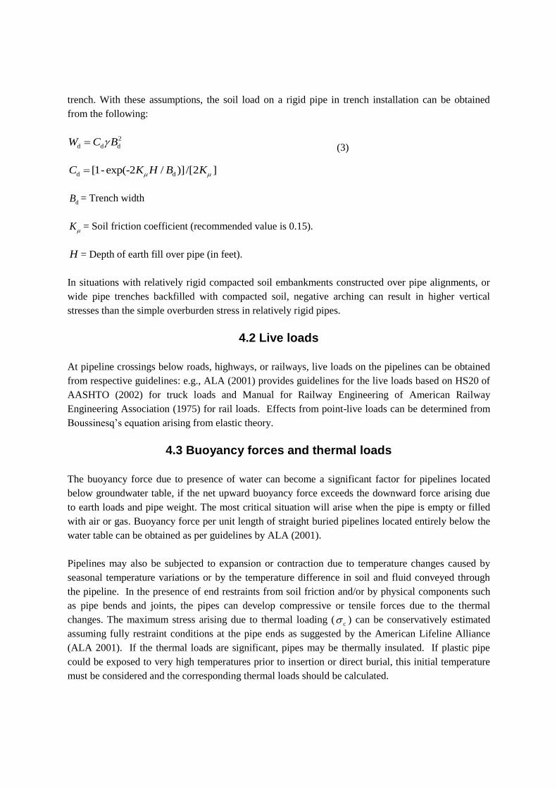
In situations with relatively rigid compacted soil embankments constructed over pipe alignments, or
wide pipe trenches backfilled with compacted soil, negative arching can result in higher vertical
stresses than the simple overburden stress in relatively rigid pipes.
4.2 Live loads
At pipeline crossings below roads, highways, or railways, live loads on the pipelines can be obtained
from respective guidelines: e.g., ALA (2001) provides guidelines for the live loads based on HS20 of
AASHTO (2002) for truck loads and Manual for Railway Engineering of American Railway
Engineering Association (1975) for rail loads. Effects from point-live loads can be determined from
Boussinesq’s equation arising from elastic theory.
4.3 Buoyancy forces and thermal loads
The buoyancy force due to presence of water can become a significant factor for pipelines located
below groundwater table, if the net upward buoyancy force exceeds the downward force arising due
to earth loads and pipe weight. The most critical situation will arise when the pipe is empty or filled
with air or gas. Buoyancy force per unit length of straight buried pipelines located entirely below the
water table can be obtained as per guidelines by ALA (2001).
Pipelines may also be subjected to expansion or contraction due to temperature changes caused by
seasonal temperature variations or by the temperature difference in soil and fluid conveyed through
the pipeline. In the presence of end restraints from soil friction and/or by physical components such
as pipe bends and joints, the pipes can develop compressive or tensile forces due to the thermal
changes. The maximum stress arising due to thermal loading (c ) can be conservatively estimated
assuming fully restraint conditions at the pipe ends as suggested by the American Lifeline Alliance
(ALA 2001). If the thermal loads are significant, pipes may be thermally insulated. If plastic pipe
could be exposed to very high temperatures prior to insertion or direct burial, this initial temperature
must be considered and the corresponding thermal loads should be calculated.

4.4 Deformations in low pressure pipes due to soil stresses
In pipes with low internal pressure subject to external static loading, a given pipeline can be
categorized as relatively rigid or relatively flexible. In rigid pipes, pipe stiffness is significantly large
compared to the stiffness of the soil, whereas, in flexible pipes, the in-plane pipe wall bending
stiffness of the pipe can be comparable to or smaller than soil. The transmission of soil loads to the
pipe is influenced by the relative stiffness of the pipe with respect to the soil – i.e., a soil-pipe
interaction problem. For example, the soil-load carrying capacity of flexible pipes made of
corrugated metal, thin-walled steel, or plastic is heavily dependent on soil-pipe interaction. Moreover,
pipe bedding and other support conditions are critical to the ability of a flexible pipe system to
withstand loads.
A given pipe, in the absence of lateral support, has only limited vertical load carrying capacity since
the tendency would be for the pipe to deflect laterally under vertical loads. In most instances, lateral
support derived from surrounding soil has an important role to play in maintaining the stability of
buried pipes. It is also of interest to note that the ring deflection at the crown will induce the soil to
arch, in turn, developing a tendency for relieving a significant portion of the vertical soil load. With
proper understanding and accounting of these combined pipe-soil interaction effects in the vertical
and horizontal directions, buried flexible pipe-soil system can be designed effectively to meet the
performance criteria.
Spangler (1956) developed a method to calculate the change in horizontal diameter of flexible metal
pipes once the total vertical load on the pipe per unit length have been determined. Similar methods
have been developed over the years (e.g. Burns and Richard 1964; Hoeg 1968; Einstein and Schwartz
1979; and Moore 1987). The soil deformation modulus ( E ) represents the supporting strength of the
surrounding soil which has considerable influence on the deflection of flexible pipes. Although the
direct measurement of E is not generally possible, this parameter is determined empirically based on
the degree of soil compaction, soil type, effective stress conditions, etc. It is important to provide
sufficiently rigid pipes in places where adequate lateral soil support cannot be assured.
5. Geotechnical hazards impacting pipelines
In addition to the loadings under operational conditions, potential loads on buried pipelines from
external hazards are of importance in assessing the performance of pipeline systems since such loads
can lead to potentially unacceptable strains in the pipelines. Typical hazards to pipelines include
damage during construction, permanent ground deformation hazards such as slope failures (Figure 4),
earthquake-induced soil displacements, ground movements at topographic discontinuities or faults,
volcanic hazards, and tsunami inundation.
In particular, earthquake-induced permanent ground deformations have been recognized as one of the
major causes of system damage and associated service disruption to lifeline facilities during past
earthquakes (Hamada and O'Rourke 1992). The extent of permanent ground displacements is
expected to increase with the increasing amplitude of earthquake accelerations and with the duration

of seismic shaking. These ground movement extents can be classified as flowslides (more than ~5m),
lateral spreading flowslides (~5 m to ~0.3 m), and ground oscillation (less than ~0.3 m). In addition
to liquefaction-induced ground movements, flotation and soil uplift could also be identified as another
potential concern in relation to the reduction in soil strength associated with liquefaction. This would
be of particular concern if the pipe trench backfill materials are poorly compacted and susceptible to
liquefaction.
When it is necessary to assess wide-area pipeline networks, regional approaches are required to
determine the ground displacement hazards (Wijewickreme et al. 2005). The approach proposed by
Youd and Perkins (1987) provides a general method for mapping the liquefaction susceptibility based
on the geological characteristics of a given area. Youd and Perkins (1987) have defined "liquefaction
susceptibility" as the capacity of the soil to resist liquefaction (see Figure 5). They suggested that the
age of the deposit, relative density, particle size, and depth to groundwater table are the primary
factors that influence the liquefaction susceptibility. This approach provides a convenient and
effective method of assessing the liquefaction susceptibility of a large area for a regional zonation
study, where general surficial geological data are available but site specific data are limited.
The methods available for the computation of earthquake-induced permanent lateral ground
displacements can be broadly classified into (a) empirical approaches developed based on measured
displacements (e.g., Youd et al. 2002); and (b) mechanistic approaches which rely more on the
principles of engineering mechanics (e.g., Newmark 1965; Byrne et al. 2004). Mechanistic methods
mostly involve finite element or finite difference analyses, which are more appropriate for detailed
site-specific analyses requiring a greater level of confidence. The estimation of earthquake-induced
ground deformations, particularly from the viewpoint of regional assessments, still relies heavily on
empirical correlations. Both empirical and mechanistic approaches would require the selection of
earthquake magnitude and epicentral distance that is consistent with the probabilistic seismic hazard
considered in the design.
Liquefaction can also produce overall volume changes in the liquefied soil mass that take place due to
the dissipation of earthquake-shear-induced excess pore water pressures. The volume changes
manifest in the field as post-liquefaction settlements, and they may occur both during and after
earthquake shaking. The adverse impacts of these settlements on the performance of structural
foundations and linear lifelines (such as buried pipelines and bridges) have been well recognized.
Several simplified methods have been proposed to estimate settlements of soils knowing the field
penetration resistance (i.e., standard penetration resistance N-value or cone penetration testing
resistance) or laboratory cyclic shear resistance and the cyclic stress ratio corresponding to the level of
ground shaking being considered (e.g., Tokimatsu and Seed 1987; Wu 2002; Wijewickreme and
Sanin 2010). Much larger vertical movements are expected at river crossings, in the vicinity of dykes,
ditches, road embankments, etc. due to distortion of the soil mass. Estimation of such vertical
deformations would require rigorous site-specific analyses.
6. Pipeline response to geotechnical hazards
Evaluation of the performance of pipeline systems under anticipated geotechnical hazards commonly
uses equations based on simplified assumptions or sophisticated numerical modeling techniques as
described in guidelines dating back to mid-1970s (e.g., ASCE 1984) and recently updated (e.g., PRCI
2009).
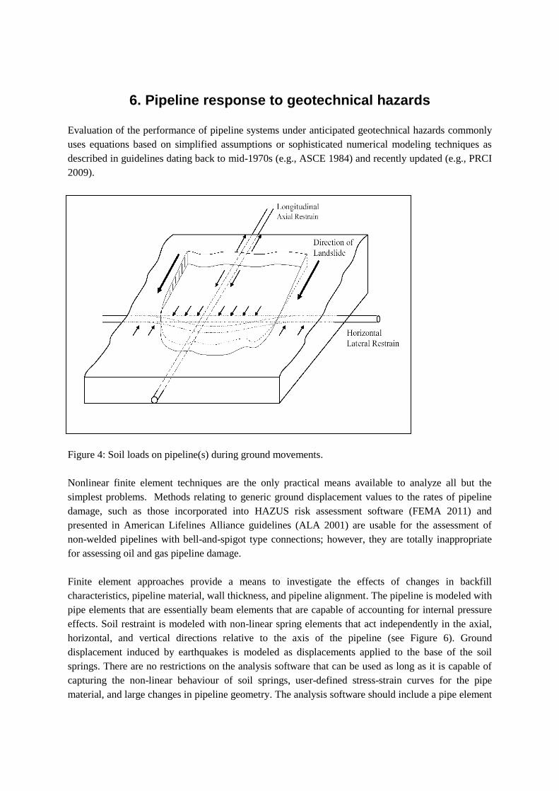
Figure 4: Soil loads on pipeline(s) during ground movements.
Nonlinear finite element techniques are the only practical means available to analyze all but the
simplest problems. Methods relating to generic ground displacement values to the rates of pipeline
damage, such as those incorporated into HAZUS risk assessment software (FEMA 2011) and
presented in American Lifelines Alliance guidelines (ALA 2001) are usable for the assessment of
non-welded pipelines with bell-and-spigot type connections; however, they are totally inappropriate
for assessing oil and gas pipeline damage.
Finite element approaches provide a means to investigate the effects of changes in backfill
characteristics, pipeline material, wall thickness, and pipeline alignment. The pipeline is modeled with
pipe elements that are essentially beam elements that are capable of accounting for internal pressure
effects. Soil restraint is modeled with non-linear spring elements that act independently in the axial,
horizontal, and vertical directions relative to the axis of the pipeline (see Figure 6). Ground
displacement induced by earthquakes is modeled as displacements applied to the base of the soil
springs. There are no restrictions on the analysis software that can be used as long as it is capable of
capturing the non-linear behaviour of soil springs, user-defined stress-strain curves for the pipe
material, and large changes in pipeline geometry. The analysis software should include a pipe element
in its element library with the capability to model internal pressure and provide output at various
circumferential locations.
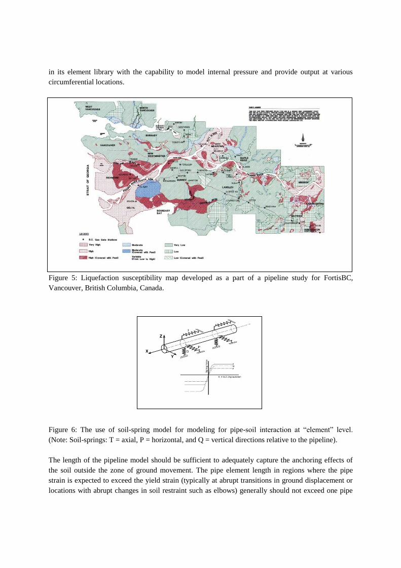
Figure 5: Liquefaction susceptibility map developed as a part of a pipeline study for FortisBC,
Vancouver, British Columbia, Canada.
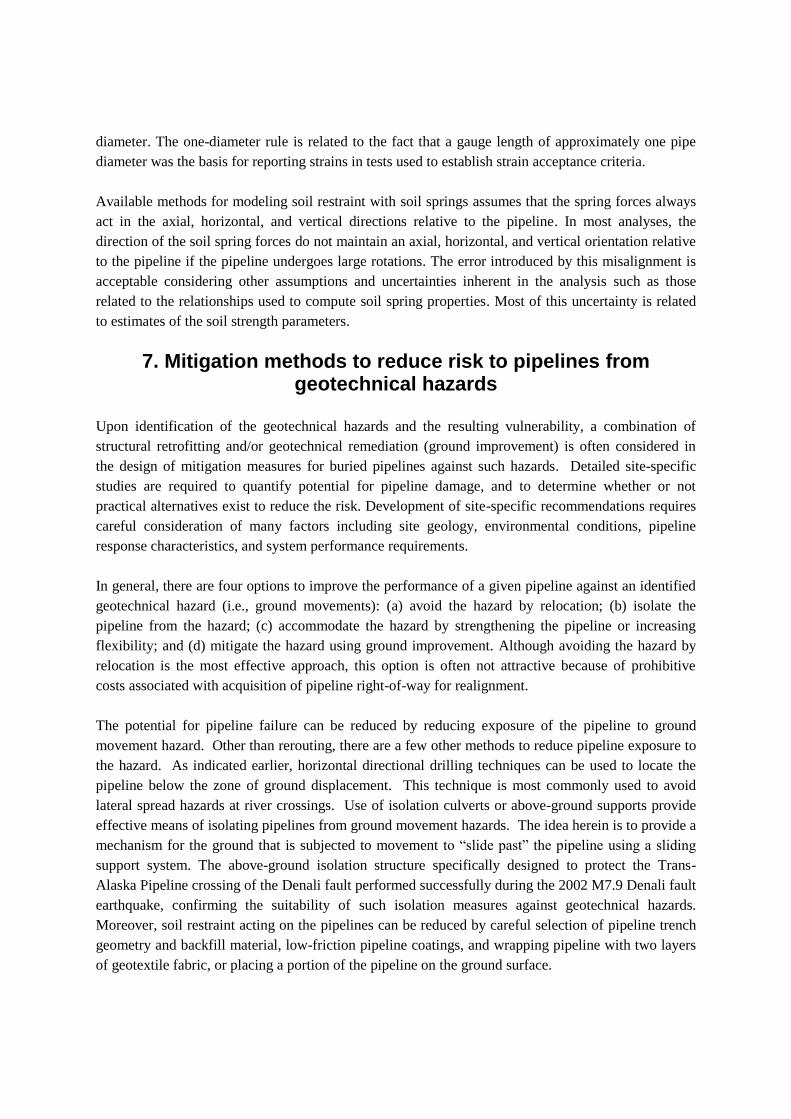
Figure 6: The use of soil-spring model for modeling for pipe-soil interaction at “element” level.
(Note: Soil-springs: T = axial, P = horizontal, and Q = vertical directions relative to the pipeline).
The length of the pipeline model should be sufficient to adequately capture the anchoring effects of
the soil outside the zone of ground movement. The pipe element length in regions where the pipe
strain is expected to exceed the yield strain (typically at abrupt transitions in ground displacement or
locations with abrupt changes in soil restraint such as elbows) generally should not exceed one pipe
diameter. The one-diameter rule is related to the fact that a gauge length of approximately one pipe
diameter was the basis for reporting strains in tests used to establish strain acceptance criteria.
Available methods for modeling soil restraint with soil springs assumes that the spring forces always
act in the axial, horizontal, and vertical directions relative to the pipeline. In most analyses, the
direction of the soil spring forces do not maintain an axial, horizontal, and vertical orientation relative
to the pipeline if the pipeline undergoes large rotations. The error introduced by this misalignment is
acceptable considering other assumptions and uncertainties inherent in the analysis such as those
related to the relationships used to compute soil spring properties. Most of this uncertainty is related
to estimates of the soil strength parameters.
7. Mitigation methods to reduce risk to pipelines from geotechnical hazards
Upon identification of the geotechnical hazards and the resulting vulnerability, a combination of
structural retrofitting and/or geotechnical remediation (ground improvement) is often considered in
the design of mitigation measures for buried pipelines against such hazards. Detailed site-specific
studies are required to quantify potential for pipeline damage, and to determine whether or not
practical alternatives exist to reduce the risk. Development of site-specific recommendations requires
careful consideration of many factors including site geology, environmental conditions, pipeline
response characteristics, and system performance requirements.
In general, there are four options to improve the performance of a given pipeline against an identified
geotechnical hazard (i.e., ground movements): (a) avoid the hazard by relocation; (b) isolate the
pipeline from the hazard; (c) accommodate the hazard by strengthening the pipeline or increasing
flexibility; and (d) mitigate the hazard using ground improvement. Although avoiding the hazard by
relocation is the most effective approach, this option is often not attractive because of prohibitive
costs associated with acquisition of pipeline right-of-way for realignment.
The potential for pipeline failure can be reduced by reducing exposure of the pipeline to ground
movement hazard. Other than rerouting, there are a few other methods to reduce pipeline exposure to
the hazard. As indicated earlier, horizontal directional drilling techniques can be used to locate the
pipeline below the zone of ground displacement. This technique is most commonly used to avoid
lateral spread hazards at river crossings. Use of isolation culverts or above-ground supports provide
effective means of isolating pipelines from ground movement hazards. The idea herein is to provide a
mechanism for the ground that is subjected to movement to “slide past” the pipeline using a sliding
support system. The above-ground isolation structure specifically designed to protect the Trans-
Alaska Pipeline crossing of the Denali fault performed successfully during the 2002 M7.9 Denali fault
earthquake, confirming the suitability of such isolation measures against geotechnical hazards.
Moreover, soil restraint acting on the pipelines can be reduced by careful selection of pipeline trench
geometry and backfill material, low-friction pipeline coatings, and wrapping pipeline with two layers
of geotextile fabric, or placing a portion of the pipeline on the ground surface.

The potential for pipeline failure can also be reduced by increasing the pipeline wall thickness and
material strength and also modifying the pipeline alignment to provide a more beneficial angle
between the direction of ground displacement and the pipeline axis. The latter option is generally
only possible during the design of new pipelines because of difficulties in obtaining new right-of-way.
Ground improvement is emerging as one of the widely adopted mitigation measures to reduce the
impact of earthquake-related ground displacement hazards. In mitigation works, the design
philosophy often revolves around implementing ground improvement measures to limit deformations
in a given pipeline to acceptable levels (e.g., design to minimize the loss of pressure integrity in
pipelines). Observations following major earthquake events have indicated that sites with improved
ground had performed well during earthquakes (Mitchell et al. 1995). The ground improvement
configurations used in practice are dependent on geotechnical risks that are to be mitigated, and these
configurations essentially fall into one of the following categories: (i) in-ground densified barrier(s)
aligned perpendicular to the direction of ground movement; and (ii) densification of wide-area
footprints beneath and around foundation footprints.
The selection of the most suitable remedial option is governed by many factors including, but not
limited to: soil conditions, space restrictions, issues related to the protection of existing structures
during ground improvement, operational constraints, environmental regulatory requirements, and land
availability. A variety of ground improvement techniques have evolved in the past few decades.
These measures include dynamic deep compaction, vibro-replacement using stone columns,
compaction piling, explosive compaction, and compaction grouting. The method of vibro-replacement
using stone columns is the most preferred technique of ground improvement in sandy soils. The
method can be effectively used to densify soils within about 25 m below existing ground level (see
Figure 7). The method is attractive because of the potential availability of drainage through stone
columns for the dissipation of excess pore water pressures in addition to the densification effect.
Compaction grouting is a useful tool not only in fine-grained soils, but also in improving sites that
have physical constraints such as low headroom. Deep dynamic compaction is another viable means
of improving the settlement characteristics and liquefaction resistance of random fills and alluvial
soils that are in a state of loose relative density and difficult for a probe to penetrate through. In-situ
verification using penetration resistance measurements confirm that this method can be used to a
maximum depth of about 10 to 12 m below existing ground level. Below this depth, the achieved
improvement in penetration resistance diminishes considerably.
Verification testing for quality control forms a key component in undertaking ground improvement
works. Evaluation of the treated soil type, method of ground improvement, and site constraints is
required in selecting the parameters and testing tools to assess the conformance of ground
improvement to specified criteria. In addition, effects from ageing and pore pressure dissipation can
have significant influence on the observations from verification testing, and they should be carefully
evaluated in determining the acceptability of a given ground improvement. The need to protect
adjacent existing pipelines/structures is often a key consideration during ground improvement. Thus,
systematic monitoring of existing facilities during ground improvement and structural evaluation of
the performance of structures based on data from monitoring is essential.

8. Challenges and future trends
The available data on soil and groundwater conditions along pipeline alignments are typically limited.
As a result, characterization of sites for soil-pipe interaction often becomes a challenging task. In
addition, high variability of soil conditions along pipeline alignments combined with complexities
associated with the mechanical behaviour of soil (e.g., stress and strain level dependence, effects of
particle fabric, effects of loading paths, etc.) present additional constraints to the level of accuracy
attainable in geotechnical evaluations. Sensitivity of the geotechnical hazard estimates to the above
considerations along with the uncertainties arising due to the difficulties in accurately defining
loadings such as earthquake shaking should be kept in mind when interpreting outcomes from hazard
assessments.
Figure 7: Illustration of the method of vibro-replacement methodology for densification of coarse-
grained soils (Geopac Inc.) [Methodology: (i) Position vibro-probe vertically over compaction point;
(ii) Penetrate to required target depth and terminate penetration; (iii) Begin feeding densification stone
backfill from the skip bucket / vibro-probe hopper for DBF or directly at ground surface with wheel
loader for WTF. (See WTF/DBF photos); (iv) Working in 0.5 m to 1.0 m depth increments starting
from the maximum penetration depth; and (v) Continue building stone column at appropriate
amperage level for each depth increment from maximum depth to the surface, while adding stone as
required with wheel loader].
8.1 Numerical modeling
In general, soil-pipe interaction problems are statically indeterminate. The use of numerical
modeling, in general, allows assessing the effect of a wide range of variables in a timely and efficient
Dry Bottom Feed (DBF)
Wet Top Feed (WTF)
manner. A vast amount of numerical analysis has also been performed to comprehend the complex
interactions between pipe and soil (e.g., Rowe and Davis 1982; Guo and Stolle 2005).
The data generated from physical testing work would be of great applicability to calibrate and verify
the numerical models. Despite the difficulties of attempting to use for routine engineering
applications, continuum modeling methods have value in increasing the understanding of the general
soil-pipe interaction problems, particularly with respect to improved definition of equivalent soil
springs. One example in this regard is the need to understand the response of pipelines subject to
ground movements that are oblique to the pipeline alignment; clearly, 3-dimensional continuum
modeling becomes valuable in the modeling of such problems that cannot be captured in a 2-
dimensional analysis. It also appears that discrete element methods seem to have a role to play in
modeling complex soil-pipe interaction situations, especially when the particulate nature of soil seems
to be the major governing factor of the observed response (e.g., modeling of the effectiveness of using
geotextile interfaces, or coarse-grained trench backfills, in in reducing soil loads on pipelines).
8.2 Non-linear pipe material behavior of plastic pipelines
Polyethylene (PE) pipes (either high density polyethylene (HDPE) or medium density polyethylene
(MDPE)) are becoming popular in natural gas distribution networks due to its lower material
installation and maintenance costs, corrosion resistance, lower friction at the interface, lightweight,
and its apparent capacity to accommodate larger displacements than steel pipes. The use of MDPE
pipes takes advantage of having higher flexibility and fracture toughness while having comparable
long-term strength and stiffness to that of HDPE (Stewart et al. 1999).
Reported research on the response of buried PE pipe systems subject to ground movement is very
limited. Considering the relatively smaller deformation stiffness and time-dependent and nonlinear
stress-strain response (viscoelastic and creep behavior) of PE pipe material, significant limitations
could arise when methods developed for steel pipes are used for evaluating PE pipes. Data from
controlled experimental work on pipelines subject to axial movement, particularly at full-scale level,
is needed to advance the knowledge of the response of buried PE pipe systems subject to ground
movement. A number of research programs have been already undertaken to investigate the response
of PE pipe systems under permanent ground movements and analytical methods have been developed
to account for the mobilization of soil loads in buried PE pipes under such ground movements
(Weerasekara and Wijewickreme 2008).
8.3 Full-scale model testing
Laboratory modeling of full-scale pipeline configurations is an attractive way of understanding the
complexities in soil-pipe interaction. For example, full-scale testing provides a meaningful approach
to estimate parameters of soil-springs to model the interaction between pipe and soil in different
directions. Physical models simulating the field situations also play a key role in calibrating and
validating the analytical approaches and numerical models. Some of the large soil chambers for full-
scale testing of pipe-soil interaction problems are available at Cornell University (Trautmann and
O’Rourke 1983), Center for Cold Oceans Resources Engineering (Paulin et al. 1997), Queen’s
University (Moore and Brachman 1994), and University of British Columbia (Wijewickreme et al.
2009; see Figure 8 and 9 for details related to the Advanced Soil Pipe Interaction Research
(ASPIReTM
) test facility at the University of British Columbia (UBC)).
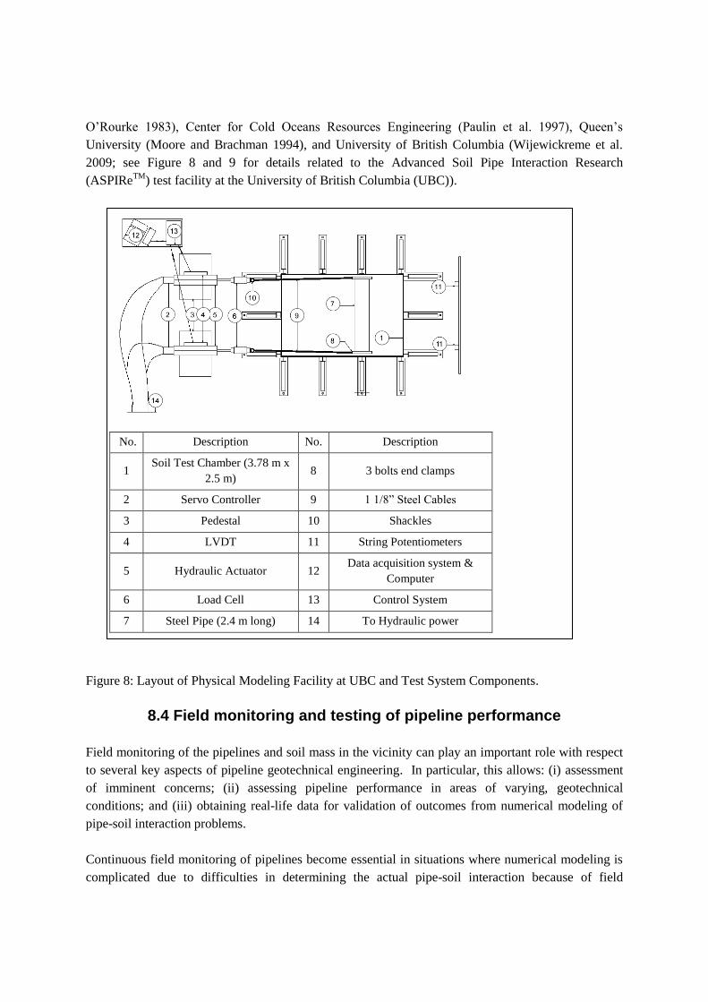
Figure 8: Layout of Physical Modeling Facility at UBC and Test System Components.
8.4 Field monitoring and testing of pipeline performance
Field monitoring of the pipelines and soil mass in the vicinity can play an important role with respect
to several key aspects of pipeline geotechnical engineering. In particular, this allows: (i) assessment
of imminent concerns; (ii) assessing pipeline performance in areas of varying, geotechnical
conditions; and (iii) obtaining real-life data for validation of outcomes from numerical modeling of
pipe-soil interaction problems.
Continuous field monitoring of pipelines become essential in situations where numerical modeling is
complicated due to difficulties in determining the actual pipe-soil interaction because of field
No. Description No. Description
1 Soil Test Chamber (3.78 m x
2.5 m) 8 3 bolts end clamps
2 Servo Controller 9 1 1/8” Steel Cables
3 Pedestal 10 Shackles
4 LVDT 11 String Potentiometers
5 Hydraulic Actuator 12 Data acquisition system &
Computer
6 Load Cell 13 Control System
7 Steel Pipe (2.4 m long) 14 To Hydraulic power
variability on many fronts. An advantage in field monitoring is that they could be conducted over
longer periods, without the space-time constraints that are common in laboratory environments.
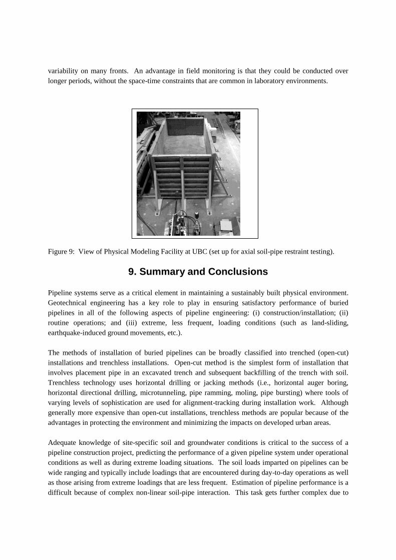
Figure 9: View of Physical Modeling Facility at UBC (set up for axial soil-pipe restraint testing).
9. Summary and Conclusions
Pipeline systems serve as a critical element in maintaining a sustainably built physical environment.
Geotechnical engineering has a key role to play in ensuring satisfactory performance of buried
pipelines in all of the following aspects of pipeline engineering: (i) construction/installation; (ii)
routine operations; and (iii) extreme, less frequent, loading conditions (such as land-sliding,
earthquake-induced ground movements, etc.).
The methods of installation of buried pipelines can be broadly classified into trenched (open-cut)
installations and trenchless installations. Open-cut method is the simplest form of installation that
involves placement pipe in an excavated trench and subsequent backfilling of the trench with soil.
Trenchless technology uses horizontal drilling or jacking methods (i.e., horizontal auger boring,
horizontal directional drilling, microtunneling, pipe ramming, moling, pipe bursting) where tools of
varying levels of sophistication are used for alignment-tracking during installation work. Although
generally more expensive than open-cut installations, trenchless methods are popular because of the
advantages in protecting the environment and minimizing the impacts on developed urban areas.
Adequate knowledge of site-specific soil and groundwater conditions is critical to the success of a
pipeline construction project, predicting the performance of a given pipeline system under operational
conditions as well as during extreme loading situations. The soil loads imparted on pipelines can be
wide ranging and typically include loadings that are encountered during day-to-day operations as well
as those arising from extreme loadings that are less frequent. Estimation of pipeline performance is a
difficult because of complex non-linear soil-pipe interaction. This task gets further complex due to
the difficulties in quantifying geotechnical hazards (e.g., landslide risk, liquefactions susceptibility
and liquefaction-induced ground displacements, etc.).
In general, there are four options to improve the performance of a given pipeline against an identified
geotechnical hazard: (a) avoid the hazard by relocation; (b) isolate the pipeline from the hazard; (c)
accommodate the hazard by strengthening the pipeline or increasing flexibility; and (d) mitigate the
hazard using ground improvement. In addition to mitigation, field monitoring and physical testing of
pipeline performance are important considerations in the performance evaluation of buried pipelines.
Acknowledgements
The research activities performed by Mr. Chris Anderson, Drs. Hamid Karimian and Lalinda
Weerasekara as team members of the author’s Advanced Soil Pipe Interaction Research (ASPIReTM
)
initiative are deeply appreciated.
References
AASHTO (2002) Standard Specifications for Highway Bridges (Seventeenth Edition), Washington,
DC, American Association for State Highway and Transportation Officials.
American Lifelines Alliance (ALA) (2001) Design of buried steel pipe, (available online
www.americanlifelinesalliance.com [accessed 28/12/2011]).
American Railway Engineering Association (1975) Manual for Railway Engineering.
ASCE (1984) Guidelines for the seismic design of oil and gas pipeline systems, American Society of
Civil Engineers, Gas and Liquid Fuel Lifelines Committee, Technical Council on Lifeline Earthquake
Engineering, pp. 157-170.
Burns J and Richard R (1964) “Attenuation of stresses around buried cylinders”, Symposium on Soil-
Structure Interaction. Tucson, AZ: American Society for Testing & Materials, West Conshohocken,
PA, pp. 379-392.
Byrne P, Park S, Beaty M, Sharp M, Gonzalez L, and Abdoun T (2004) “Numerical modeling of
liquefaction and comparison with centrifuge tests.” Canadian Geotechnical Journal 41(2):193-211.
Chehab A and Moore I (2008) “Axial force in pulled-into-place HDPE pipes during and after
installation”. 3rd Brazilian Conference on Trenchless Technology and 1st Latin America No-Dig, Sao
Paolo, Brazil, 10 pp.
Einstein H and Schwartz C (1979) “Simplified analysis for tunnel supports” Journal of Geotechnical
Engineering, 105(4): 499-518.
FEMA (2011) HAZUS user manual, Federal Emergency Management Agency. (available online
www.fema.gov/hazus/ [accessed online 28/12/2011]).
Guo P and Stolle D (2005) “Lateral pipe-soil interaction in sand with reference to scale effect.”
Journal of Geotechnical and Geoenvironmental Engineering, 131(30): 338-349.
Hamada M and O’Rourke T, Eds. (1992) Case studies of liquefaction and lifelines performance
during past earthquakes: Japanese case studies, Technical Report NCEER-92-0001, Vol. 1, Buffalo,
NY: National Center for Earthquake Engineering Research, State University of New York.
Hoeg K (1968) “Stresses against underground structural cylinders.” Journal of Soil Mechanics and
Foundation Engineering, 94(4): 833-858.
Mitchell J, Baxter C, and Munson T (1995) “Performance of improved ground during earthquakes.”
In RD Hryciw, Ed., Soil Improvement for Earthquake Hazard Mitigation, Geotechnical Special
Publication GSP No. 49, Proceedings of sessions, conjunction with the ASCE Conference, San Diego,
CA, 22-26 October 1995, New York, NY.
Moore I (1987) “The elastic stability of shallow buried tubes.” Géotechnique 37(2):151-161.
Moore I (2010) “Design Tools for Directional Drilling”, Association of Professional Engineers and
Geoscientists of British Columbia, Annual Conference & AGM, 21-23 October, 2010, Whistler, BC.
Moore I and Brachman R (1994) “Three dimensional analysis of flexible circular cylinders.” Journal
of Geotechnical Engineering, 120(10): 1829-1844.
North American Society for Trenchless Technology (NASTT) (2012), General website, (available
online http://www.nastt.org/ [accessed on 30/11/2012]).
Newmark N (1965) “Effect of earthquakes on Dams and embankments.” Geotechnique 15: 139-160.
Paulin M, Phillips R, Clark J, Hurley S, and Trigg A (1997) ‘Establishment of a full-scale
pipeline/soil interaction test facility and results from lateral and axial investigations in sand,’ 16th
international conference of offshore mechanics and arctic engineering, OMAE 5, American Society
of Mechanical Engineers, pp. 139-146.
Pipeline Hazardous Material Safety Administration (PHMSA) (2011) (available online
http://www.phmsa.dot.gov [accessed 28/12/2011]).
Pipeline Research Council International (PRCI) (2009) Guidelines for constructing natural gas and
liquid hydrocarbon pipelines in areas subject to landslide and subsidence hazards, Catalog No.
L52292.

Rowe R and Davis E (1982) “The behaviour of anchor plates in sand.” Geotechnique 32(1): 25-41.
Spangler M (1956) “Stresses in pressure pipe-lines and protective casing pipes”. Journal of Structural
Engineering (82): 1-33.
Stewart H, Bilgin O, O’Rourke T and Keeney T (1999) Technical reference for improved design and
construction to account for thermal loads in plastic gas pipelines. Technical report, Ithaca, NY:
Cornell University.
Tokimatsu, K and Seed, BH (1987) “Evaluation of settlements due to earthquake shaking.” Journal of
Geotechnical Engineering, 1138(8): 861–879.
Trautmann C and O'Rourke T (1983) Behaviour of Pipe in dry sandunder lateral and uplift loading.
Geotechnical Engineering Report, Ithaca, NY, Cornell University.
Weidlich I and Wijewickreme D (2012) “Factors Influencing Soil Friction Forces on Buried Pipes
Used for District Heating”, 13th International Symposium on District Heating and Cooling,
Copenhagen, Denmark, 2-4 September, 2012.
Weerasekara L and Wijewickreme D (2008) “Mobilization of soil loads on buried polyethylene
natural gas pipelines subject to relative axial displacements.” Canadian Geotechnical Journal, 45(9):
1237-1249.
Wijewickreme D, Honegger D, Mitchell A, and Fitzell T (2005) “Seismic vulnerability assessment
and retrofit of a major natural gas transmission system: A case history.” Earthquake Spectra, 21(2):
539-567.
Wijewickreme D, Karimian H and Honegger D (2009) “Response of buried steel pipelines subjected
to relative axial soil movement.” Canadian Geotechnical Journal, 46(7): 735-752.
Wijewickreme D, and Sanin M (2010) “Post-cyclic reconsolidation strains in low-plastic Fraser River
silt due to dissipation of excess pore water pressures.” Journal of Geotechnical and
Geoenvironmental Engineering 136(10): 1347-1357.
Wu, J (2002) Liquefaction triggering and post-liquefaction deformation of Monterey 0/30 sand under
unidirectional cyclic simple shear loading, Ph.D. thesis, University of California, Berkeley, CA.
Youd L and Perkins D (1987) “Mapping liquefiable ground failure potential.” Journal of the
Geotechnical Engineering Division, American Society of Civil Engineers, 104(4): 433-445.
Youd T, Hansen C, and Bartlett S (2002) “Revised multilinear regression equations for prediction of
lateral spread displacement.” Journal of Geotechnical and Geoenvironmental Engineering, 128(12):
1007–1017.