Embed Size (px)
Citation preview
ROLE OF
PHASOR MEASUREMENT UNIT
(PMU) IN WIDE AREA MONITORING
AND CONTROL
KRISH NARENDRA
ERLPhase Power Technology Ltd
Winnipeg, Manitoba ,CANADA
www.erlphase.com
OUTLINE
• INTRODUCTION
• INTERPRETATION OF SYNCHROPHASOR STANDARD
• CALIBRATION AND TESTING OF PMU
• COMMUNICATION OF PMU DATA
• APPLICATION OF PMUs FOR WIDE AREA MONITORING AND CONTROL
• CONCLUSIONS
• QUESTIONS
• HANDS ON WITH PMU
INTRODUCTION
• Definition of Phasor
• Global Time Reference
• Importance of Global Time Reference
• Phasor Measurement Unit (PMU)
• PMU Functionality with Relays and DFRs
• Phasor Data Concentrator (PDC)
• Super PDC

Definition of Phasor
•Complex number
•Single frequency
•Steady State Conditions
Global Time Reference
• Coordinated Universal Time (UTC)- 00 longitude
• GPS (Global Positioning System) synchronized with UTC (< 1 uS)
• GPS receivers sends global time via different time code format
• Most widely used is IRIG-B (Inter Range Instrumentation Group)
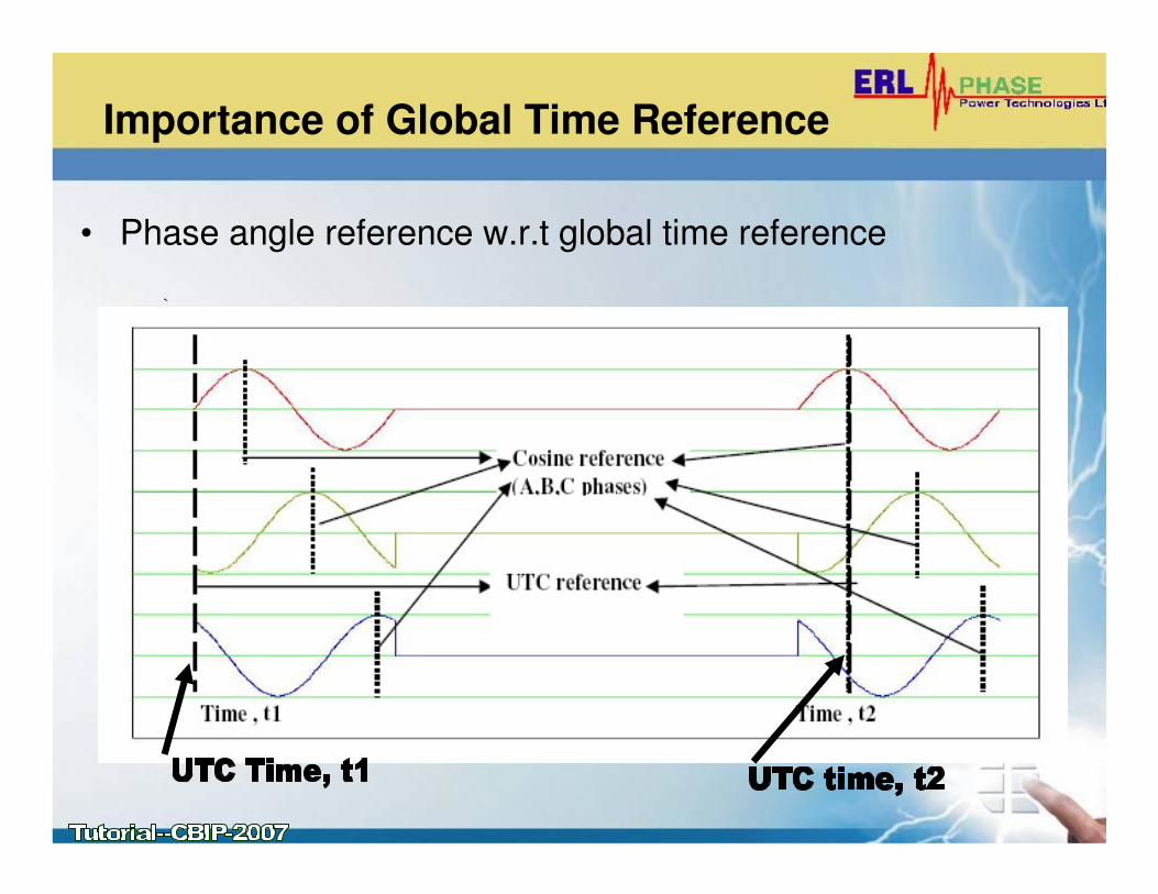
Importance of Global Time Reference
• Phase angle reference w.r.t global time reference
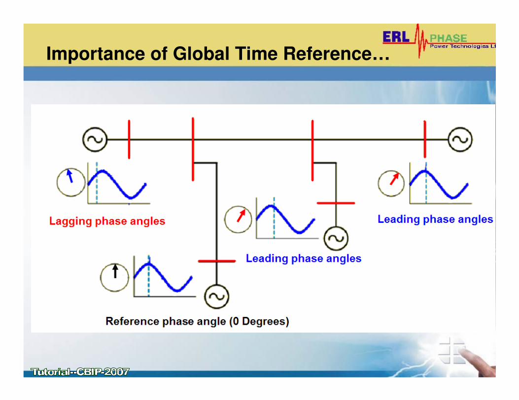
Importance of Global Time Reference…
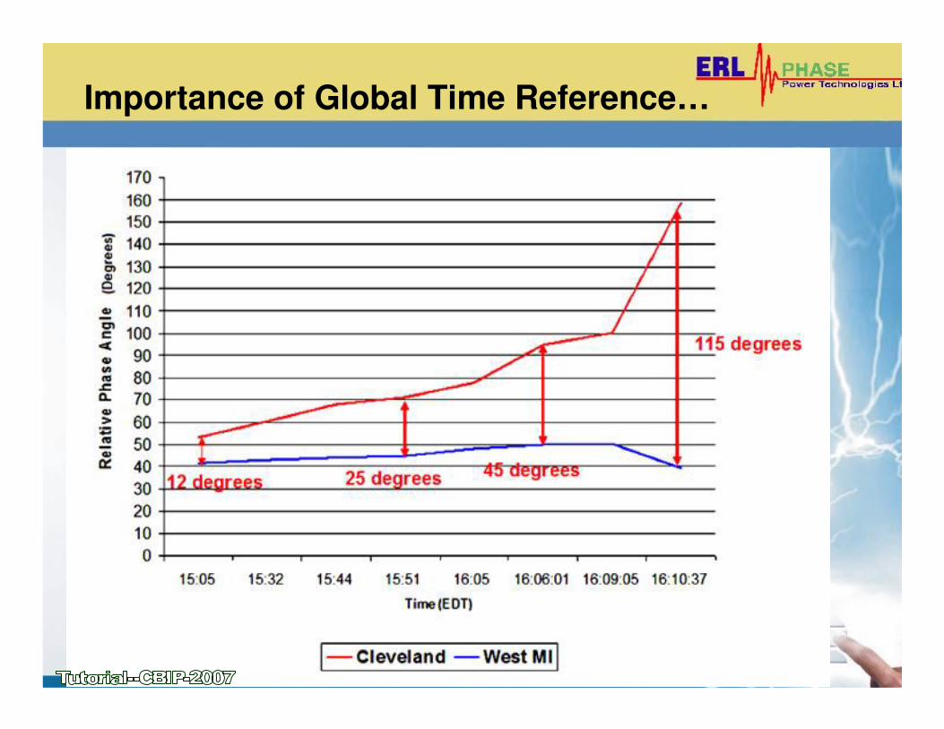
Importance of Global Time Reference…
Phasor Measurement Unit (PMU)
• A device (mostly microprocessor based) which
reports the magnitude and phase angle of an
analog and /or derived phasor with respect to
the global time reference, as per the
synchrophasor standards ( IEEE 1344, IEEE
C37.118).
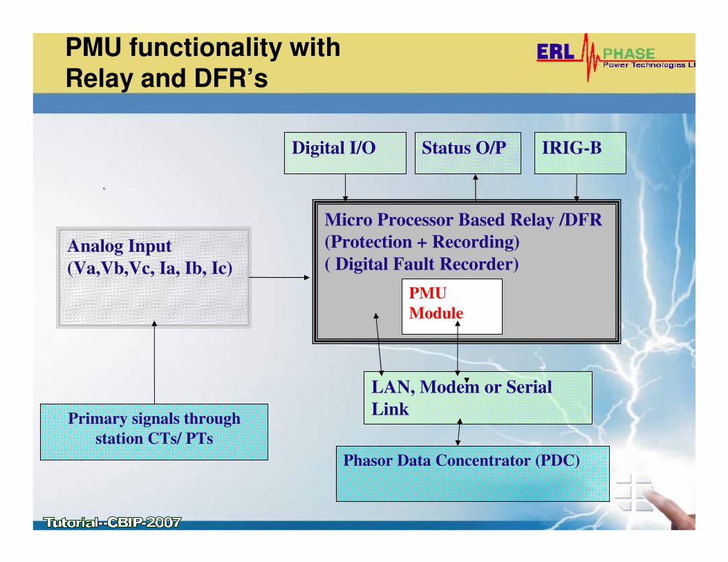
PMU functionality with
Relay and DFR’s
Analog Input
(Va,Vb,Vc, Ia, Ib, Ic)
Micro Processor Based Relay /DFR
(Protection + Recording)
( Digital Fault Recorder)
PMU
Module
Digital I/O Status O/P
LAN, Modem or Serial
Link
Phasor Data Concentrator (PDC)
IRIG-B
Primary signals through
station CTs/ PTs
Phasor Data Concentrator (PDC)
• A Software application runs on normal desktop
PC- and collects data from multiple PMUs
• Dedicated Server application designed to accept
several PMU data and analyze the data
depending on application requirement
• Dedicated hardware/software to do real time
monitoring and control studies using PMU data
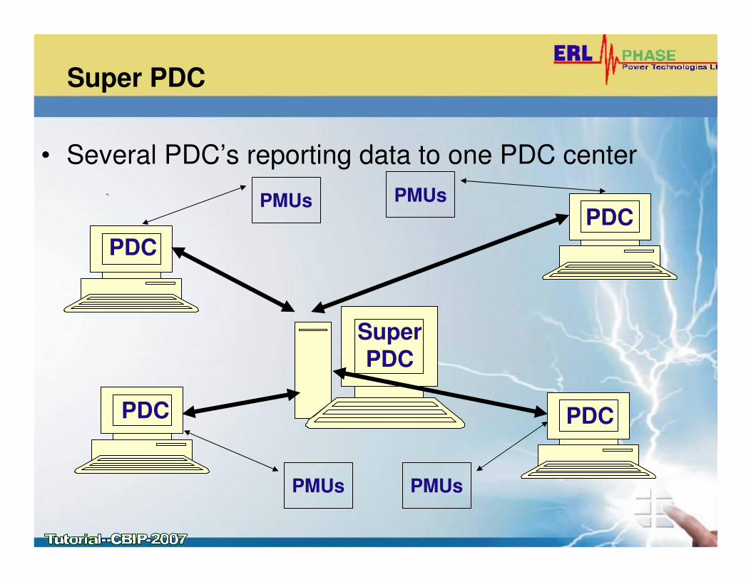
Super PDC
• Several PDC’s reporting data to one PDC center
PDC
PDC
PDC
PDC
Super PDC
PMUs
PMUs
PMUs
PMUs
INTERPRETATION OF
SYNCHROPHASOR STANDARD (C37.118)
• PMU protocol (C37.118)
• Difference between IEEE 1344 and IEEE C37.118
• Total Vector Error (TVE)
• Compliance Levels as defined in C37.118
• Limitations – under dynamic system conditions
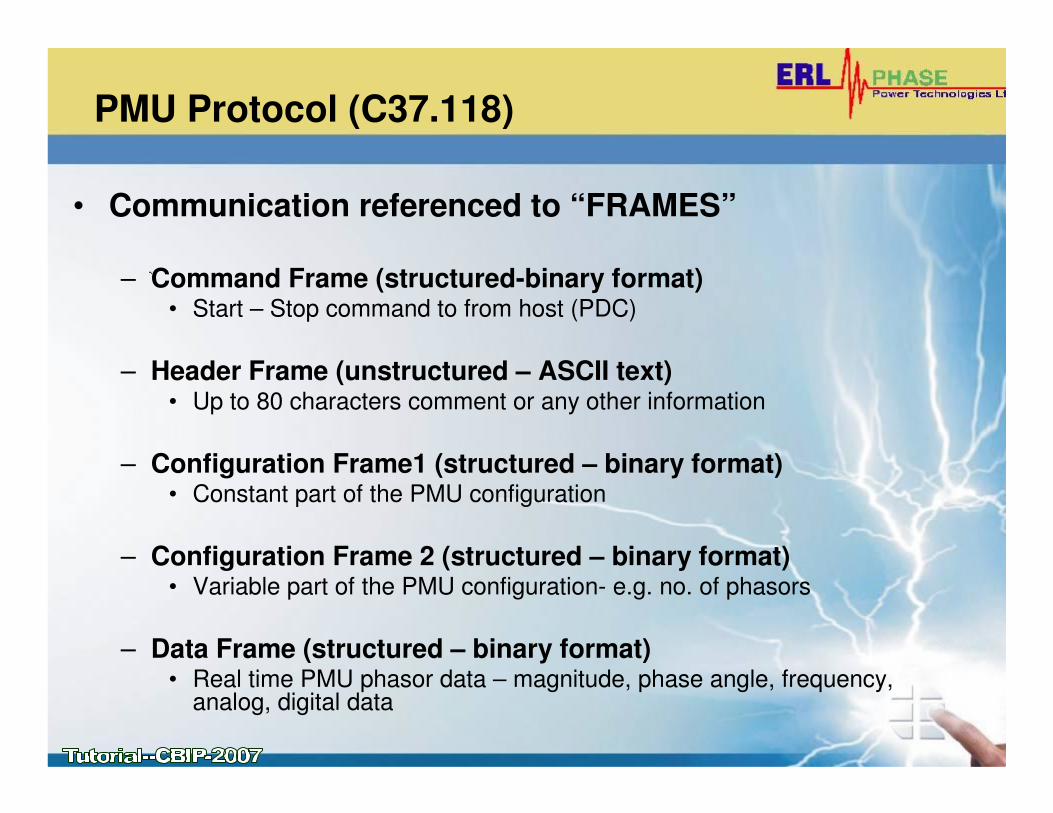
PMU Protocol (C37.118)
• Communication referenced to “FRAMES”
– Command Frame (structured-binary format)• Start – Stop command to from host (PDC)
– Header Frame (unstructured – ASCII text)• Up to 80 characters comment or any other information
– Configuration Frame1 (structured – binary format)• Constant part of the PMU configuration
– Configuration Frame 2 (structured – binary format)• Variable part of the PMU configuration- e.g. no. of phasors
– Data Frame (structured – binary format)• Real time PMU phasor data – magnitude, phase angle, frequency,
analog, digital data
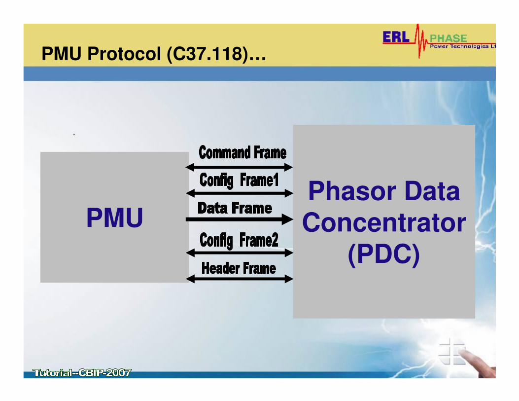
PMU Protocol (C37.118)…
Phasor Data
Concentrator
(PDC)
PMU
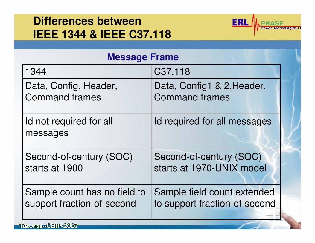
Differences between
IEEE 1344 & IEEE C37.118
Second-of-century (SOC) starts at 1970-UNIX model
Second-of-century (SOC) starts at 1900
Sample field count extended to support fraction-of-second
Sample count has no field to support fraction-of-second
Id required for all messagesId not required for all
messages
Data, Config1 & 2,Header,
Command frames
Data, Config, Header,
Command frames
C37.1181344
Message Frame
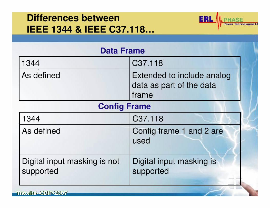
Differences between
IEEE 1344 & IEEE C37.118…
Extended to include analog
data as part of the data
frame
As defined
C37.1181344
Data Frame
Config frame 1 and 2 are used
As defined
Digital input masking is
supported
Digital input masking is not
supported
C37.1181344
Config Frame
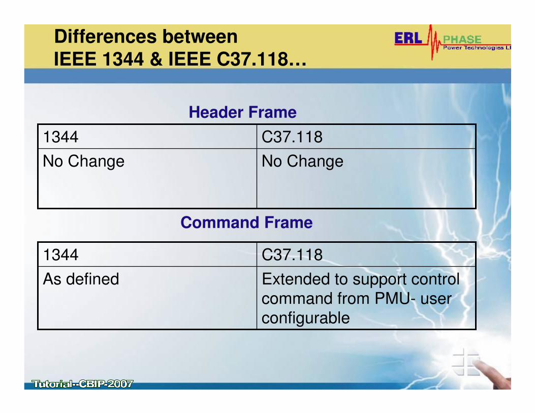
Differences between
IEEE 1344 & IEEE C37.118…
No ChangeNo Change
C37.1181344
Header Frame
Extended to support control
command from PMU- user configurable
As defined
C37.1181344
Command Frame
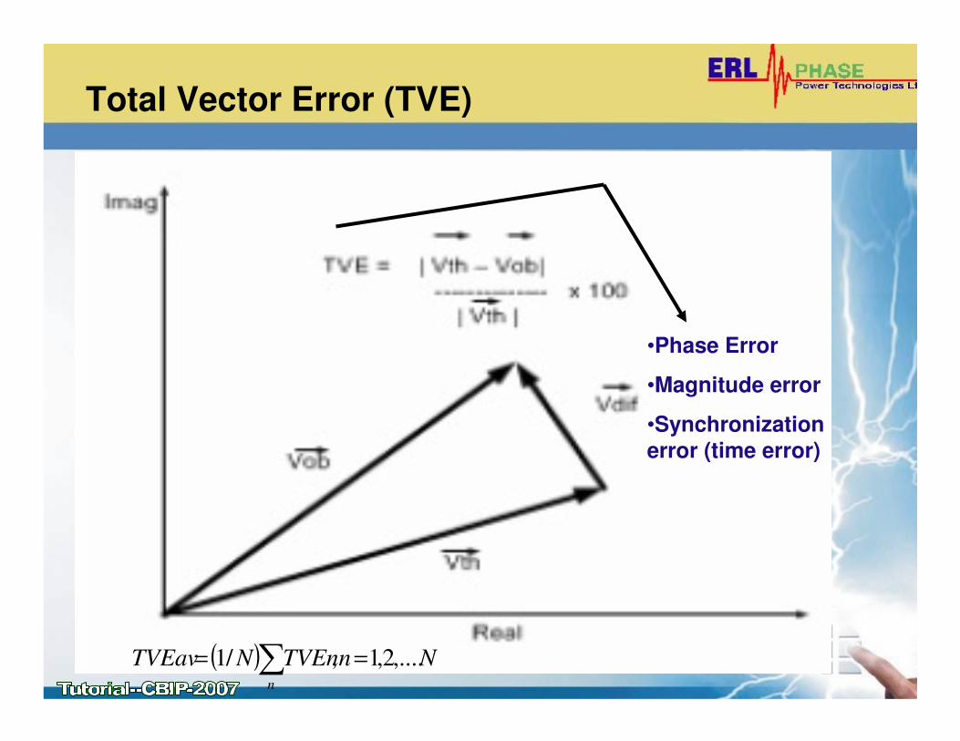
Total Vector Error (TVE)
•Phase Error
•Magnitude error
•Synchronization
error (time error)
( ) NnTVEnNTVEav
n
,....2,1,/1 == ∑

Compliance Levels (C37.118)
C37.118 Limitations
• Applicable under steady-state conditions
• Difficult to extend the concept of TVE under dynamic conditions – due to different algorithms used to evaluate
the phasor
• Out of band frequency compliance - difficult to realize in testing
• Not focused on communication issues
CALIBRATION AND TESTING OF PMU
• Sources of errors in measuring analog signal
• Impact of error on PMUs accuracy
• Calibration of PMU
• Challenges of testing PMUs
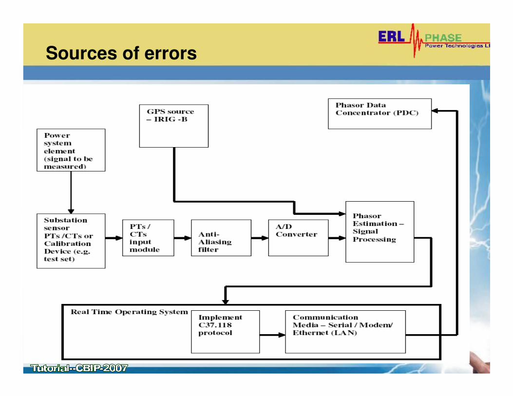
Sources of errors
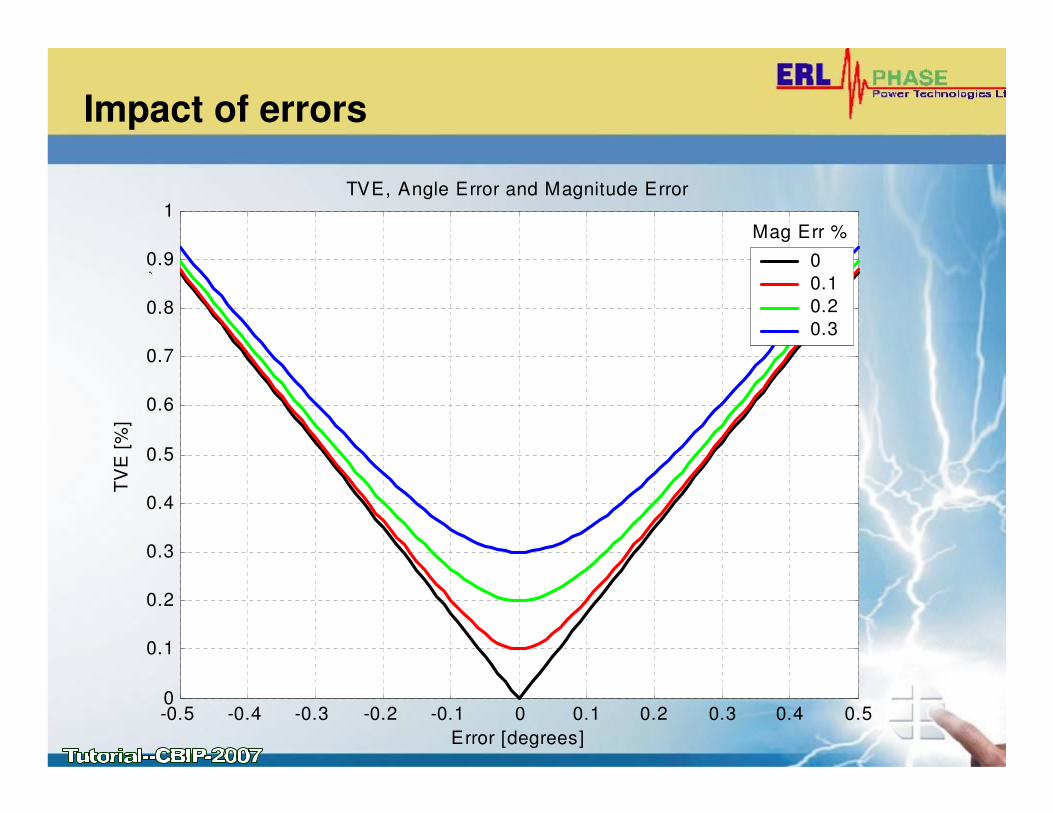
Impact of errors
-0.5 -0.4 -0.3 -0.2 -0.1 0 0.1 0.2 0.3 0.4 0.50
0.1
0.2
0.3
0.4
0.5
0.6
0.7
0.8
0.9
1
Error [degrees]
TV
E [
%]
TVE, Angle Error and Magnitude Error
0
0.1
0.2
0.3
Mag Err %
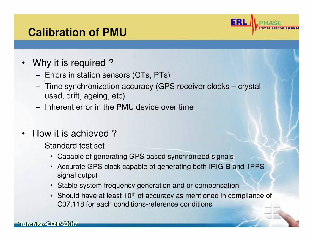
Calibration of PMU
• Why it is required ?
– Errors in station sensors (CTs, PTs)
– Time synchronization accuracy (GPS receiver clocks – crystal used, drift, ageing, etc)
– Inherent error in the PMU device over time
• How it is achieved ?
– Standard test set
• Capable of generating GPS based synchronized signals
• Accurate GPS clock capable of generating both IRIG-B and 1PPS
signal output
• Stable system frequency generation and or compensation
• Should have at least 10th of accuracy as mentioned in compliance of
C37.118 for each conditions-reference conditions
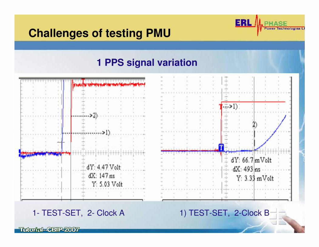
Challenges of testing PMU
1- TEST-SET, 2- Clock A 1) TEST-SET, 2-Clock B
1 PPS signal variation
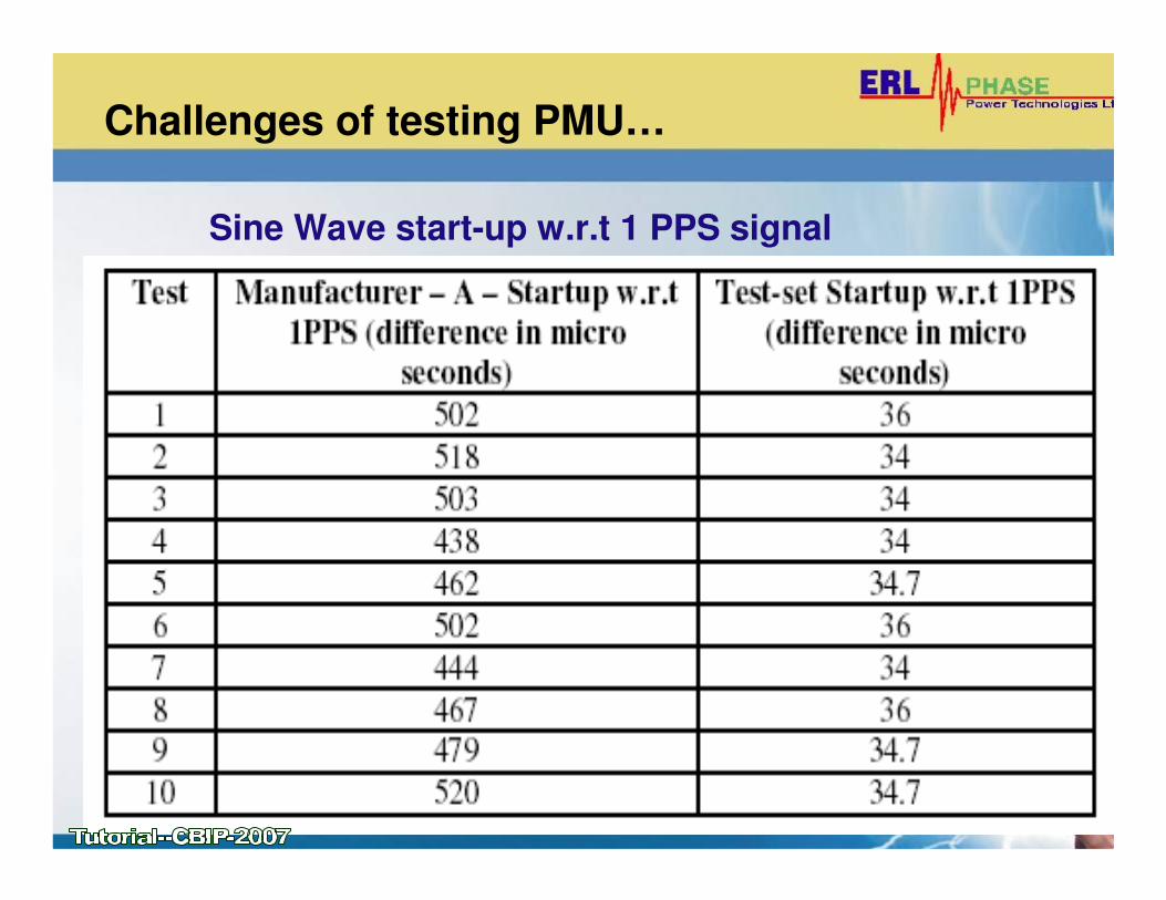
Challenges of testing PMU…
Sine Wave start-up w.r.t 1 PPS signal
Challenges of testing PMU…
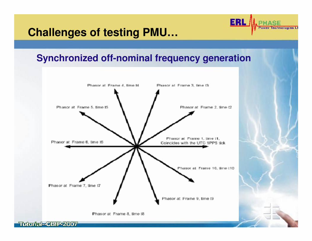
Synchronized off-nominal frequency generation
Challenges of testing PMU…
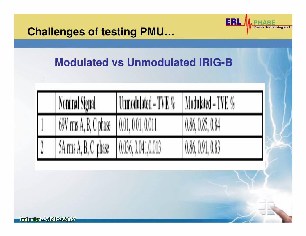
Modulated vs Unmodulated IRIG-B
Challenges of testing PMU…
• Harmonic distortion
– Standard requires upto 50th harmonic needs to be
tested- difficult to generate harmonics upto 50th
• Out-of-band interfering signal
– Could be additive, subtractive, multiplicative – not clear
• Communication issues
– Limited testing is done with TVA – PDC
– Need more real time field data to prove communication
reliability
COMMUNICATION OF PMU DATA
• PMU Data Frame
• Different methods of communication with the PMU
• TCP vs UDP protocol
• Typical case studies of traffic over the LAN
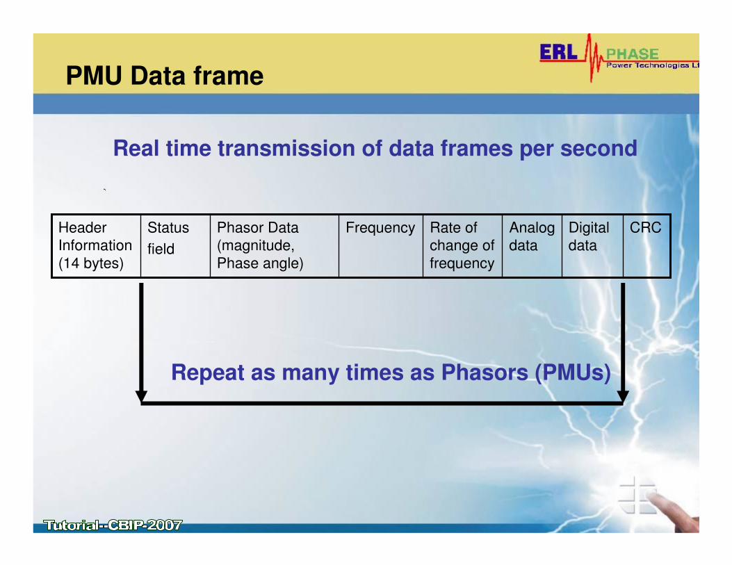
PMU Data frame
Header
Information
(14 bytes)
Digital
data
Analog
data
CRCRate of
change of
frequency
FrequencyPhasor Data
(magnitude,
Phase angle)
Status
field
Real time transmission of data frames per second
Repeat as many times as Phasors (PMUs)
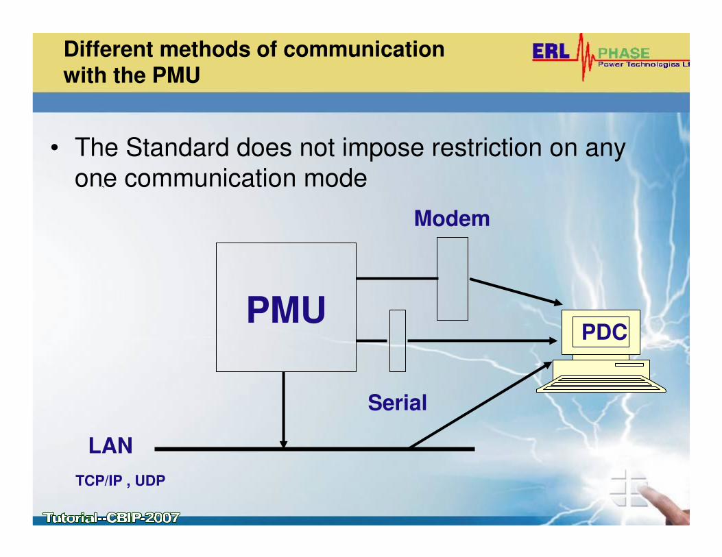
Different methods of communicationwith the PMU
• The Standard does not impose restriction on any
one communication mode
PMU
LAN
Serial
Modem
TCP/IP , UDP
PDC
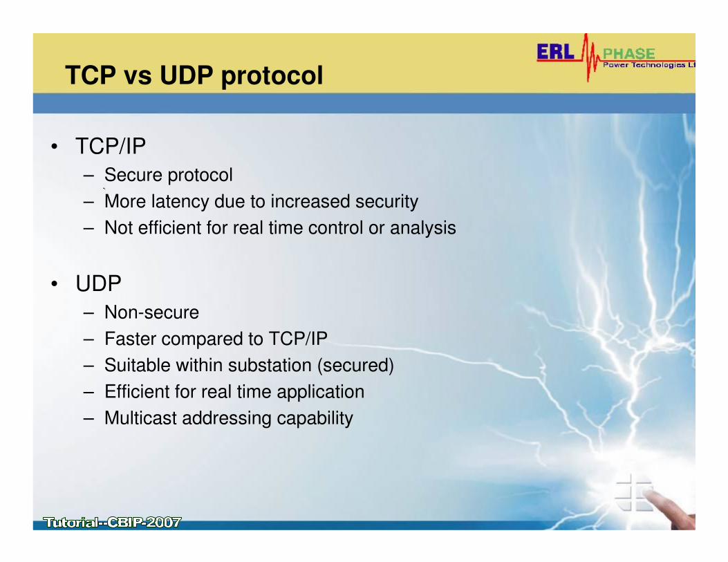
TCP vs UDP protocol
• TCP/IP
– Secure protocol
– More latency due to increased security
– Not efficient for real time control or analysis
• UDP
– Non-secure
– Faster compared to TCP/IP
– Suitable within substation (secured)
– Efficient for real time application
– Multicast addressing capability
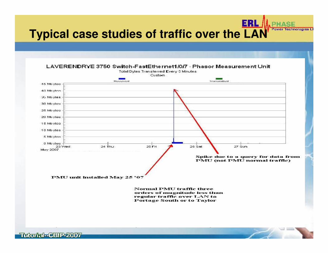
Typical case studies of traffic over the LAN
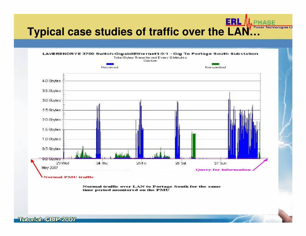
Typical case studies of traffic over the LAN…

Typical case studies of traffic over the LAN…

PMUs FOR WIDE AREA MONITORING
AND CONTROL
• Wide Area Monitoring and Control with PMUs
– Utilizing PMU data for various Power System Applications analysis and modelling
– Strategic Deployment of PMUs
– Discussion on real time control using PMU data

PMU data for power system application
• Real Time Power System Measurement Snap Shot
– State “estimation” is simply “measurement”
– No need to solve cumbersome iterative state estimation
– Wide area is observable in real time

PMU data for power system application…
• Transient Stability
– Real time information helpful in observing stability of the system (e.g. PV curve)
– Small Signal analysis (e.g. modal analysis, using Prony’stechnique)
– Real time stability control is possible – especially with synchronized sampling on PMUs
PMU data for power system application…
• System Modelling
– Transmission line modelling
– Driving point impedance is helpful to under stand frequency response of the system
– Useful for training intelligent systems- such as – Neural Network, Fuzzy logic – training samples are available with real system data
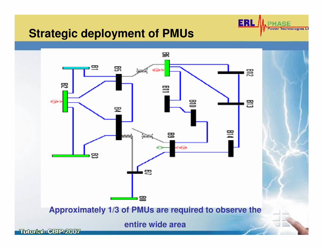
Strategic deployment of PMUs
Approximately 1/3 of PMUs are required to observe the
entire wide area
Real time control
• Possible, but not very easy
• Just the real time data availability is not enough
• Real time capabilities to analyze good-and-bad data
• High availability of communication system (reliability), and security are very important
• Interoperability of different vendor PMUs

CONCLUSIONS
• PMUs can provide useful information for Wide Area Monitoring, Protection and Control
• Need to establish interoperability of PMUs (dynamic performance)
• Need for more customer friendly PMU calibration and testing devices to meet C37.118 compliance levels
• PMU technology can be best utilized with active participation and cooperation from Utilities, Industries, Academic Institutions, and organizations like NASPI, PSRC, NIST, EPRI etc.
Acknowledgements
• NASPI – North American Synchrophasor Initiative- Damir Novosel, Vahid Vadani, Jerry Stenbakken, Henry Huang and (other PSTT members)
• WECC / BPA / PNNL- Ken Martin, John Hauer
• Manitoba Hydro - Tony Weekes
• Virginia Tech University – Arun G Phadke
• North Eastern University – Ali Abur
• PSRC- Power System Relaying Committee (WG H11)
• Others – Directly or indirectly referenced


![Monitoring of Three-Phase Signals based on Singular-Value ...pierre.granjon/doc/publi/artTSG19.pdfusing synchronized devices called Phasor Measurement Units (PMU) [4]–[6]. In particular,](https://img.pdfslide.net/doc/110x75/610996fd3089447ddd20a8a2/monitoring-of-three-phase-signals-based-on-singular-value-using-synchronized.jpg)


![PMU Placement to Ensure Observable Freqqyuency and Voltage Dynamics…electriconf/2012/slides/Section D2-P1/2... · References [1] Ali Abur, Optimal Plancement of Phasor Measurement](https://img.pdfslide.net/doc/110x75/5a827d217f8b9ada388de528/pmu-placement-to-ensure-observable-freqqyuency-and-voltage-dynamics-electriconf2012slidessection.jpg)