Embed Size (px)
Citation preview
Roll-aRound tool Cabinet
© 2014 August Home Publishing Co.
1 WoodsmithPlans.com SN12532 ©2014 August Home Publishing Co. All Rights Reserved.
dream shop project
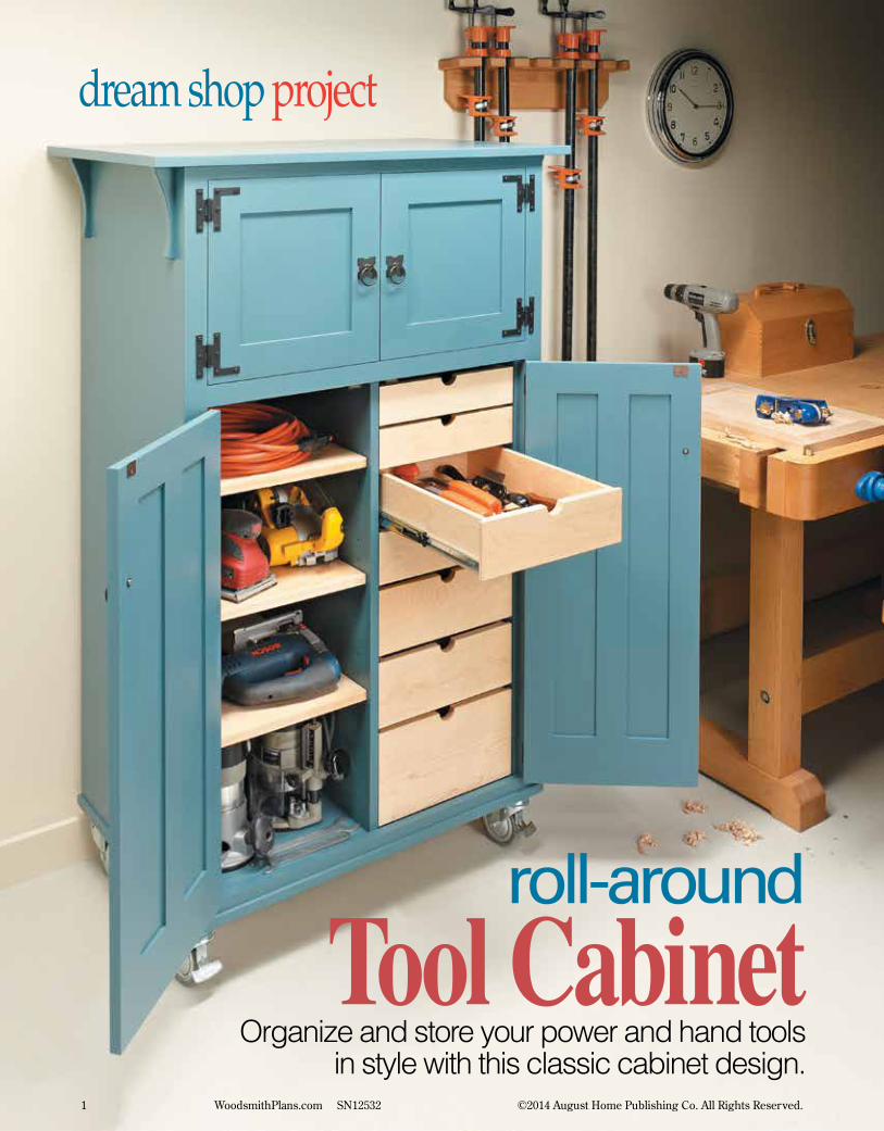
Organize and store your power and hand tools in style with this classic cabinet design.
roll-around
Tool Cabinet
2 WoodsmithPlans.com SN12532 ©2014 August Home Publishing Co. All Rights Reserved.
When I saw the conept drawings for this tool chest, I thought it hit all the right but-tons for a fantastic shop project. It’s packed full of storage options, including a bank of drawers and adjustable shelves. All of this is hidden inside a classic, “country Craftsman” cabinet that looks more like an armoire worthy of storing your most-prized tools. The heavy-duty locking casters make
it easy to keep your tools at hand wherever and whenever you need them.
The best part is, the woodworking is all pretty straightforward. You start by build-ing the basic case, add the top and bottom, and then concentrate on the shelves and drawers with full-extension slides. Finally, you close everything up with the two pairs of frame and panel doors.
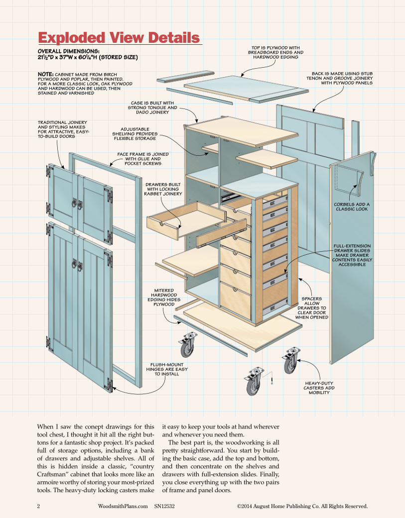
OVERALL DIMENSIONS:211⁄2"D x 37"W x 601⁄4"H (STORED SIZE)
Exploded View Details
NOTE: cabinet made from birch plywood and poplar, then painted. for a more classic look, oak plywood and hardwood can be used, then stained and varnished
top is plywood with breadboard ends and
hardwood edging
corbels add a classic look
back is made using stub tenon and groove joinery
with plywood panels
case is built with strong tongue and
dado joinery
face frame is joined with glue and pocket screws
traditional joinery and styling makes for attractive, easy-to-build doors
flush-mount hinges are easy
to install
heavy-duty casters add
mobility
mitered hardwood
edging hides plywood
spacers allow
drawers to clear door
when opened
drawers built with locking
rabbet joinery
adjustable shelving provides flexible storage
full-extension drawer slides make drawer
contents easily accessible
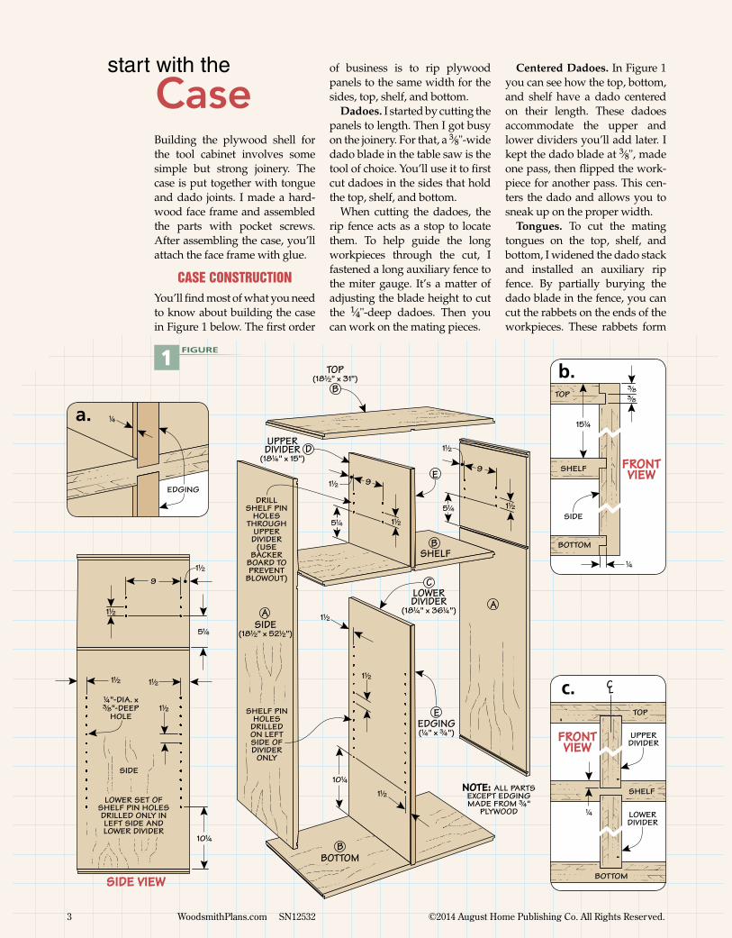
Building the plywood shell for the tool cabinet involves some simple but strong joinery. The case is put together with tongue and dado joints. I made a hard-wood face frame and assembled the parts with pocket screws. After assembling the case, you’ll attach the face frame with glue.
case constructionYou’ll find most of what you need to know about building the case in Figure 1 below. The first order
of business is to rip plywood panels to the same width for the sides, top, shelf, and bottom.
Dadoes. I started by cutting the panels to length. Then I got busy on the joinery. For that, a 3⁄8"-wide dado blade in the table saw is the tool of choice. You’ll use it to first cut dadoes in the sides that hold the top, shelf, and bottom.
When cutting the dadoes, the rip fence acts as a stop to locate them. To help guide the long workpieces through the cut, I fastened a long auxiliary fence to the miter gauge. It’s a matter of adjusting the blade height to cut the 1⁄4"-deep dadoes. Then you can work on the mating pieces.
start with the
CaseCentered Dadoes. In Figure 1
you can see how the top, bottom, and shelf have a dado centered on their length. These dadoes accommodate the upper and lower dividers you’ll add later. I kept the dado blade at 3⁄8", made one pass, then flipped the work-piece for another pass. This cen-ters the dado and allows you to sneak up on the proper width.
Tongues. To cut the mating tongues on the top, shelf, and bottom, I widened the dado stack and installed an auxiliary rip fence. By partially burying the dado blade in the fence, you can cut the rabbets on the ends of the workpieces. These rabbets form
5!/4
ASIDE
(18!/2" x 52!/2")
B
B
B
A
C
D
E
E
SHELF PIN HOLES
DRILLED ON LEFT SIDE OF DIVIDER
ONLY
NOTE: ALL PARTS EXCEPT EDGING MADE FROM #/4"
PLYWOOD
TOP(18!/2" x 31")
LOWER DIVIDER
(18!/4" x 36!/4")
UPPERDIVIDER
(18!/4" x 15")
EDGING(!/4" x #/4")
SHELF
BOTTOM
DRILL SHELF PIN
HOLES THROUGH
UPPER DIVIDER
(USE BACKER
BOARD TO PREVENT
BLOWOUT)
5!/4
1!/2
1!/2
99
1!/2
1!/2
1!/2
1!/2
1!/2
10!/4
1 FIGURE
1!/2
LOWER SET OF SHELF PIN HOLES DRILLED ONLY IN LEFT SIDE AND LOWER DIVIDER
9
1!/2
5!/4
1!/2
1!/2
1!/2
10!/4
!/4"-DIA. x#/8"-DEEP
HOLE
SIDE
SIDE VIEW
!/4
EDGING
a.
FRONT VIEW
TOP
SHELF
BOTTOM
SIDE
!/4
#/8
#/8
15!/4
b.
FRONT VIEW
CL
!/4
TOP
SHELF
BOTTOM
UPPER DIVIDER
LOWERDIVIDER
c.
3 WoodsmithPlans.com SN12532 ©2014 August Home Publishing Co. All Rights Reserved.
4 WoodsmithPlans.com SN12532 ©2014 August Home Publishing Co. All Rights Reserved.
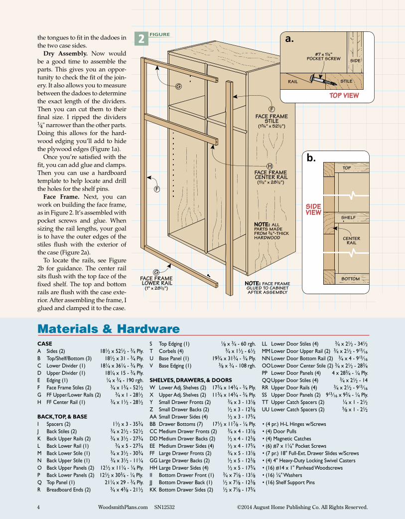
the tongues to fit in the dadoes in the two case sides.
Dry Assembly. Now would be a good time to assemble the parts. This gives you an oppor-tunity to check the fit of the join-ery. It also allows you to measure between the dadoes to determine the exact length of the dividers. Then you can cut them to their final size. I ripped the dividers 1⁄4" narrower than the other parts. Doing this allows for the hard-wood edging you’ll add to hide the plywood edges (Figure 1a).
Once you’re satisfied with the fit, you can add glue and clamps. Then you can use a hardboard template to help locate and drill the holes for the shelf pins.
Face Frame. Next, you can work on building the face frame, as in Figure 2. It’s assembled with pocket screws and glue. When sizing the rail lengths, your goal is to have the outer edges of the stiles flush with the exterior of the case (Figure 2a).
To locate the rails, see Figure 2b for guidance. The center rail sits flush with the top face of the fixed shelf. The top and bottom rails are flush with the case exte-rior. After assembling the frame, I glued and clamped it to the case.
Materials & HardwareCASEA Sides (2) 181⁄2 x 521⁄2 - 3⁄4 Ply.B Top/Shelf/Bottom (3) 181⁄2 x 31 - 3⁄4 Ply.C Lower Divider (1) 181⁄4 x 361⁄4 - 3⁄4 Ply.D Upper Divider (1) 181⁄4 x 15 - 3⁄4 Ply.E Edging (1) 1⁄4 x 3⁄4 - 190 rgh.F Face Frame Stiles (2) 3⁄4 x 13⁄4 - 521⁄2G FF Upper/Lower Rails (2) 3⁄4 x 1 - 281⁄2H FF Center Rail (1) 3⁄4 x 11⁄2 - 281⁄2
BACK, TOP, & BASEI Spacers (2) 11⁄2 x 3 - 353⁄4J Back Stiles (2) 3⁄4 x 21⁄2 - 521⁄2K Back Upper Rails (2) 3⁄4 x 31⁄2 - 273⁄4L Back Lower Rail (1) 3⁄4 x 5 - 273⁄4M Back Lower Stile (1) 3⁄4 x 31⁄2 - 303⁄4N Back Upper Stile (1) 3⁄4 x 31⁄2 - 111⁄4O Back Upper Panels (2) 121⁄2 x 111⁄4 - 1⁄4 Ply. P Back Lower Panels (2) 121⁄2 x 303⁄4 - 1⁄4 Ply.Q Top Panel (1) 211⁄4 x 29 - 3⁄4 Ply.R Breadboard Ends (2) 3⁄4 x 43⁄8 - 211⁄2
S Top Edging (1) 1⁄8 x 3⁄4 - 60 rgh.T Corbels (4) 3⁄4 x 11⁄2 - 61⁄2U Base Panel (1) 193⁄4 x 313⁄4 - 3⁄4 Ply.V Base Edging (1) 3⁄8 x 3⁄4 - 108 rgh.
SHELVES, DRAWERS, & DOORSW Lower Adj. Shelves (2) 173⁄4 x 143⁄4 - 3⁄4 Ply.X Upper Adj. Shelves (2) 113⁄4 x 143⁄4 - 3⁄4 Ply.Y Small Drawer Fronts (2) 3⁄4 x 3 - 131⁄8Z Small Drawer Backs (2) 1⁄2 x 3 - 123⁄8AA Small Drawer Sides (4) 1⁄2 x 3 - 173⁄4BB Drawer Bottoms (7) 171⁄2 x 117⁄8 - 1⁄4 Ply.CC Medium Drawer Fronts (2) 3⁄4 x 4 - 131⁄8DD Medium Drawer Backs (2) 1⁄2 x 4 - 123⁄8EE Medium Drawer Sides (4) 1⁄2 x 4 - 173⁄4FF Large Drawer Fronts (2) 3⁄4 x 5 - 131⁄8GG Large Drawer Backs (2) 1⁄2 x 5 - 123⁄8HH Large Drawer Sides (4) 1⁄2 x 5 - 173⁄4II Bottom Drawer Front (1) 3⁄4 x 71⁄8 - 131⁄8JJ Bottom Drawer Back (1) 1⁄2 x 71⁄8 - 123⁄8KK Bottom Drawer Sides (2) 1⁄2 x 71⁄8 - 173⁄4
LL Lower Door Stiles (4) 3⁄4 x 21⁄2 - 341⁄2MM Lower Door Upper Rail (2) 3⁄4 x 21⁄2 - 913⁄16
NN Lower Door Bottom Rail (2) 3⁄4 x 4 - 913⁄16
OO Lower Door Center Stile (2) 3⁄4 x 21⁄2 - 283⁄4PP Lower Door Panels (4) 4 x 283⁄4 - 1⁄4 Ply.QQ Upper Door Stiles (4) 3⁄4 x 21⁄2 - 14RR Upper Door Rails (4) 3⁄4 x 21⁄2 - 913⁄16
SS Upper Door Panels (2) 913⁄16 x 93⁄4 - 1⁄4 Ply.TT Upper Catch Spacers (2) 1⁄4 x 1 - 21⁄2UU Lower Catch Spacers (2) 5⁄8 x 1 - 21⁄2
• (4 pr.) H-L Hinges w/Screws• (4) Door Pulls• (4) Magnetic Catches• (6) #7 x 11⁄4" Pocket Screws• (7 pr.) 18" Full-Ext. Drawer Slides w/Screws• (4) 4" Heavy-Duty Locking Swivel Casters • (16) #14 x 1" Panhead Woodscrews• (16) 1⁄4" Washers • (16) Shelf Support Pins
H
G
FFACE FRAME
STILE(1#/4" x 52!/2")
NOTE: FACE FRAME GLUED TO CABINET AFTER ASSEMBLY
NOTE: ALL PARTS MADE FROM #/4"-THICK HARDWOOD
GFACE FRAME LOWER RAIL
(1" x 28!/2")
FACE FRAME CENTER RAIL
(1!/2" x 28!/2")
F
TOP VIEW
#7 x 1!/4" POCKET SCREW
STILERAIL
SIDE
a.
SIDE VIEW
TOP
SHELF
BOTTOM
CENTER RAIL
b.
2 FIGURE
5 WoodsmithPlans.com SN12532 ©2014 August Home Publishing Co. All Rights Reserved.
NOTE: PANELS MADE
FROM !/4" PLYWOOD
CL
O
N
M
L
K
I
I
J
J
K
O
P
P
SPACER(1!/2" x 3" - 35#/4")
BACK STILE(#/4" x 2!/2" - 52!/2")
BACK UPPER RAIL
(#/4" x 3!/2" - 27#/4")
BACK LOWER RAIL
(#/4" x 5" - 27#/4")
BACK LOWER STILE
(#/4" x 3!/2" - 30#/4")
BACK UPPER STILE
(#/4" x 3!/2" - 11!/4")
BACK UPPER PANEL
(12!/2" x 11!/4")
BACK LOWER PANEL
(12!/2" x 30#/4")
NOTE: BACK PANEL ASSEMBLY GLUED TO BACK OF CABINET
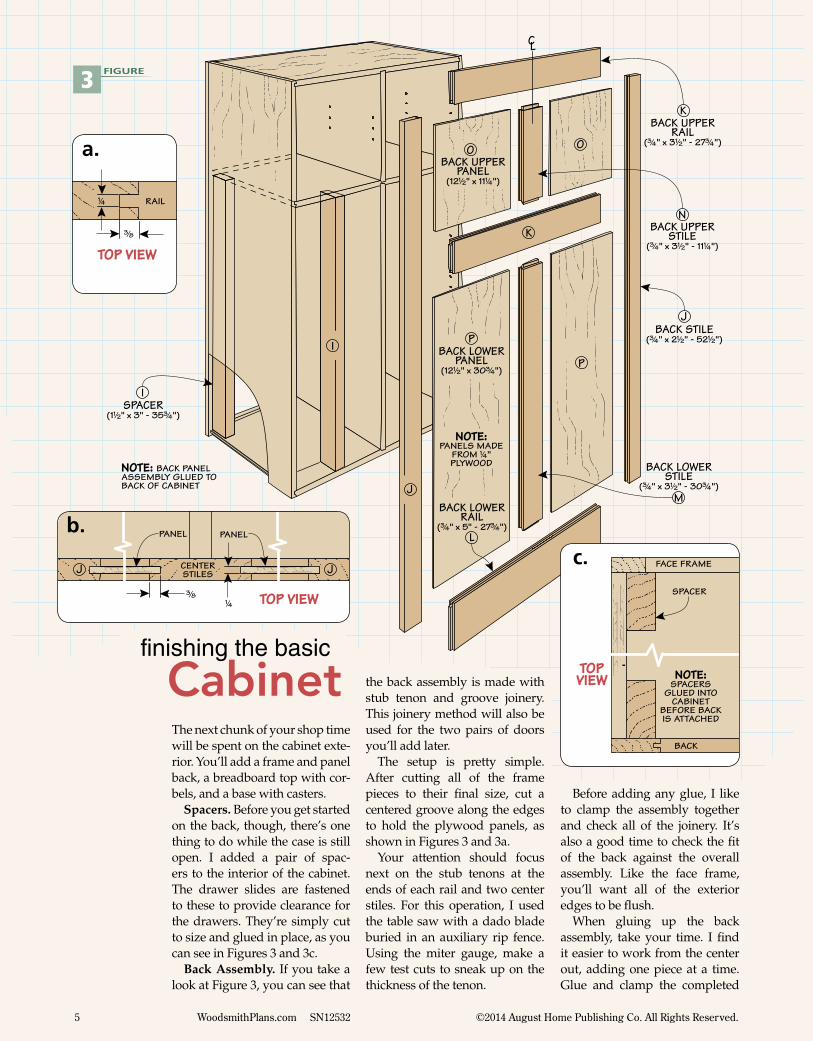
The next chunk of your shop time will be spent on the cabinet exte-rior. You’ll add a frame and panel back, a breadboard top with cor-bels, and a base with casters.
Spacers. Before you get started on the back, though, there’s one thing to do while the case is still open. I added a pair of spac-ers to the interior of the cabinet. The drawer slides are fastened to these to provide clearance for the drawers. They’re simply cut to size and glued in place, as you can see in Figures 3 and 3c.
Back Assembly. If you take a look at Figure 3, you can see that
Before adding any glue, I like to clamp the assembly together and check all of the joinery. It’s also a good time to check the fit of the back against the overall assembly. Like the face frame, you’ll want all of the exterior edges to be flush.
When gluing up the back assembly, take your time. I find it easier to work from the center out, adding one piece at a time. Glue and clamp the completed
3 FIGURE
finishing the basic
Cabinet
RAIL
TOP VIEW
!/4
#/8
a.
PANEL
CENTERSTILES
TOP VIEW
J
#/8!/4
PANEL
J
b.
TOP VIEW NOTE:
SPACERSGLUED INTO
CABINET BEFORE BACKIS ATTACHED
SPACER
BACK
FACE FRAMEc.
the back assembly is made with stub tenon and groove joinery. This joinery method will also be used for the two pairs of doors you’ll add later.
The setup is pretty simple. After cutting all of the frame pieces to their final size, cut a centered groove along the edges to hold the plywood panels, as shown in Figures 3 and 3a.
Your attention should focus next on the stub tenons at the ends of each rail and two center stiles. For this operation, I used the table saw with a dado blade buried in an auxiliary rip fence. Using the miter gauge, make a few test cuts to sneak up on the thickness of the tenon.
6 WoodsmithPlans.com SN12532 ©2014 August Home Publishing Co. All Rights Reserved.
1!/2
S
Q
R
R
T
TOPEDGING(!/8" x #/4")
TOP PANEL(21!/4" x 29" - #/4" Ply.) BREADBOARD END
(#/4" x 4#/8" - 21!/2")
CORBEL(#/4" x 1!/2" - 6!/2")
CUT BACK ENDSOF TONGUE TO ACCOMMODATE
EDGING
SOFTEN EDGES AFTER ASSEMBLY
SOFTEN EDGES WITH SANDPAPER
4
FRONTVIEW
#/8
BREADBOARD END
CORBEL
!/4
b.
VUBASE PANEL
(19#/4" x 31#/4" - #/4" Ply.)BASE EDGING
(#/8" x #/4")
4" LOCKING SWIVEL CASTER
VSOFTEN EDGES
BEFORE ATTACHING PANEL
TO CASE
#14 x 1"PANHEAD SCREW
AND WASHER
5
FRONTVIEW
BASE PANEL
!/16"RAD.
b.
TOP VIEW
BASE EDGING
BASE PANEL
MITER EDGING TO FIT AROUND
PANEL
a.
CORBELPATTERN
(FULL SCALE)
1!/2
6!/2
BREADBOARDEND
TOP VIEW
!/8
EDGING
a.
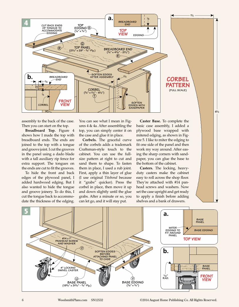
assembly to the back of the case. Then you can start on the top.
Breadboard Top. Figure 4 shows how I made the top with breadboard ends. The ends are joined to the top with a tongue and groove joint. I cut the grooves in the panel using a dado blade with a tall auxiliary rip fence for extra support. The tongues on the ends are cut to fit the grooves.
To hide the front and back edges of the plywood panel, I added hardwood edging. But I also wanted to hide the tongue and groove joinery. To do this, I cut the tongue back to accommo-date the thickness of the edging.
You can see what I mean in Fig-ures 4 & 4a. After assembling the top, you can simply center it on the case and glue it in place.
Corbels. The graceful curve of the corbels adds a trademark Craftsman-style touch to the cabinet. You can use the full-size pattern at right to cut and sand them to shape. To fasten them in place, I used a rub joint. First, apply a thin layer of glue (I use original Titebond because it “grabs” quicker). Press the corbel in place, then move it up and down slightly until the glue grabs. After a minute or so, you can let go, and it will stay put.
Caster Base. To complete the basic case assembly, I added a plywood base wrapped with mitered edging, as shown in Fig-ure 5. I like to miter the edging to fit one side of the panel and then work my way around. After eas-ing the sharp corners with sand-paper, you can glue the base to the bottom of the cabinet.
Casters. The locking, heavy-duty casters make the cabinet easy to roll across the shop floor. They’re attached with #14 pan-head screws and washers. Now set the case upright and get ready to apply a finish before adding shelves and a bank of drawers.
1!/2
S
Q
R
R
T
TOPEDGING(!/8" x #/4")
TOP PANEL(21!/4" x 29" - #/4" Ply.) BREADBOARD END
(#/4" x 4#/8" - 21!/2")
CORBEL(#/4" x 1!/2" - 6!/2")
CUT BACK ENDSOF TONGUE TO ACCOMMODATE
EDGING
SOFTEN EDGES AFTER ASSEMBLY
SOFTEN EDGES WITH SANDPAPER
7 WoodsmithPlans.com SN12532 ©2014 August Home Publishing Co. All Rights Reserved.
Applying a finish to the inte-rior and exterior of the cabinet is easier now, before you add the drawers. I applied a coat of acrylic latex primer and sanded it smooth before spraying on the color coat. I used Benjamin Moore’s Aura satin acrylic paint, Fair Isle Blue (CSP-715) followed by General Finishes’ High Perfor-mance flat, water-based varnish (refer to Sources on page 13).
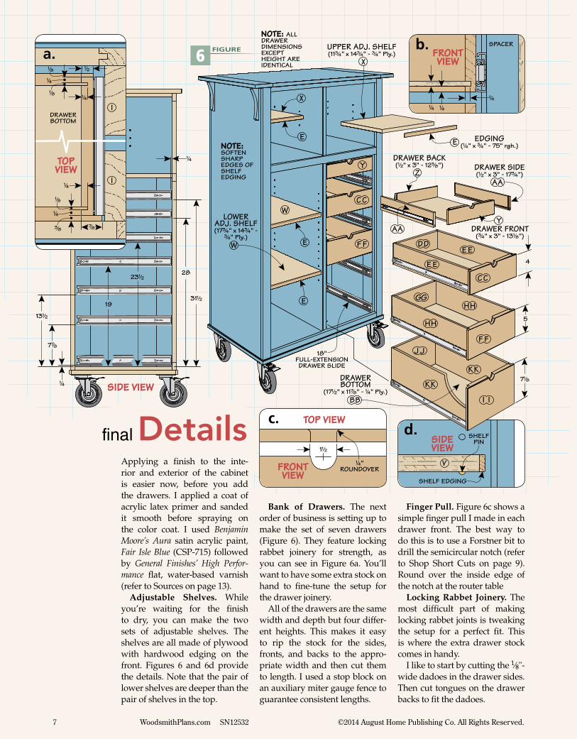
Adjustable Shelves. While you’re waiting for the finish to dry, you can make the two sets of adjustable shelves. The shelves are all made of plywood with hardwood edging on the front. Figures 6 and 6d provide the details. Note that the pair of lower shelves are deeper than the pair of shelves in the top.
final Details
Bank of Drawers. The next order of business is setting up to make the set of seven drawers (Figure 6). They feature locking rabbet joinery for strength, as you can see in Figure 6a. You’ll want to have some extra stock on hand to fine-tune the setup for the drawer joinery.
All of the drawers are the same width and depth but four differ-ent heights. This makes it easy to rip the stock for the sides, fronts, and backs to the appro-priate width and then cut them to length. I used a stop block on an auxiliary miter gauge fence to guarantee consistent lengths.
Finger Pull. Figure 6c shows a simple finger pull I made in each drawer front. The best way to do this is to use a Forstner bit to drill the semicircular notch (refer to Shop Short Cuts on page 9). Round over the inside edge of the notch at the router table
Locking Rabbet Joinery. The most difficult part of making locking rabbet joints is tweaking the setup for a perfect fit. This is where the extra drawer stock comes in handy.
I like to start by cutting the 1⁄8"-wide dadoes in the drawer sides. Then cut tongues on the drawer backs to fit the dadoes.
SIDE VIEW
SHELF EDGING
V
SHELFPIN
NOTE: ALLDRAWER DIMENSIONS EXCEPTHEIGHT ARE IDENTICAL
7!/8
ZY
E
X
W
BB
HH
II
KK
F F
GG
EE
JJ
DD
AA
UPPER ADJ. SHELF(11#/4" x 14#/4" - #/4" Ply.)
EDGING(!/4" x #/4" - 75" rgh.)
LOWERADJ. SHELF(17#/4" x 14#/4" -
#/4" Ply.)
E
E
W
X
E
18" FULL-EXTENSION DRAWER SLIDE
F F
CC
CC
YAA
DRAWER SIDE(!/2" x 3" - 17#/4")
DRAWER FRONT(#/4" x 3" - 13!/8")
DRAWER BACK(!/2" x 3" - 12#/8")
EE
HH
KK
4
5
DRAWERBOTTOM
(17!/2" x 11&/8" - !/4" Ply.)
NOTE: SOFTENSHARPEDGES OF SHELFEDGING
6 FIGURE FRONT VIEW
SPACER
!/4 !/4
!/4
b.
SIDE VIEW!/4
7&/8
13!/2
19
23!/228
31!/2
!/4
DRAWERBOTTOM
TOP VIEW
I
&/8
!/4
!/8
#/8
!/4
!/4
!/8
!/8
!/2
!/4
I
a.
FRONT VIEW
TOP VIEW
1!/2
!/4"ROUNDOVER
c.d.
8 WoodsmithPlans.com SN12532 ©2014 August Home Publishing Co. All Rights Reserved.
< Hinges. Align the door in the opening using shims then fasten the hinge in place.
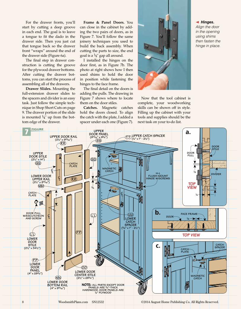
For the drawer fronts, you’ll start by cutting a deep groove in each end. The goal is to leave a tongue to fit the dado in the drawer side. Then you just cut that tongue back so the drawer front “wraps” around the end of the drawer side (Figure 6a).
The final step in drawer con-struction is cutting the groove for the plywood drawer bottoms. After cutting the drawer bot-toms, you can start the process of assembling all of the drawers.
Drawer Slides. Mounting the full-extension drawer slides to the spacers and divider is an easy task. Just follow the simple tech-nique in Shop Short Cuts on page 9. The drawer portion of the slide is mounted 1⁄4" up from the bot-tom edge of the drawer.
Frame & Panel Doors. You can close in the cabinet by add-ing the two pairs of doors, as in Figure 7. You’ll follow the same joinery techniques you used to build the back assembly. When cutting the parts to size, the end goal is a 1⁄8" gap all around.
I installed the hinges on the door first, as in Figure 7b. The photo at right shows how I then used shims to hold the door in position while fastening the hinges to the face frame.
The final detail on the doors is adding the pulls. The drawing in Figure 7 shows where to locate them on the door stiles.
Catches. Magnetic catches hold the doors closed. To align the catch with the plate, I added a spacer under each one (Figure 7).
Now that the tool cabinet is complete, your woodworking skills can be shown off in style.Filling up the cabinet with your tools and supplies should be the next task on your to-do list.
NOTE: ALL PARTS EXCEPT DOOR PANELS ARE #/4"-THICK
HARDWOOD. DOOR PANELS ARE !/4" PLYWOOD
CL
SST T
MM
OO
PP
RR
LL
UPPERDOOR PANEL(9!#/16" x 9#/4") UPPER CATCH SPACER
(!/4" x 1" - 2!/2")
UULOWERCATCH
SPACER(%/8" x 1" - 2!/2")
LOWERDOORSTILE
(2!/2" x 34!/2")
LOWER DOORUPPER RAIL(2!/2" x 9!#/16")
LOWER DOORBOTTOM RAIL
(4" x 9!#/16")
LOWER DOORCENTER STILE
(2!/2" x 28#/4")
LOWERDOORPANEL
(4" x 28#/4")
UPPERDOOR STILE
(2!/2" x 14")
UPPER DOOR RAIL(2!/2" x 9!#/16")
H-LFLUSH-MOUNT
HINGE W/SCREWS
MAGNETIC CATCH
CATCH PLATE
CATCH PLATE
DOOR PULLW/ESCUTCHEON
AND SCREW
NN
LL
PP
RR
#/4
CL
7
CL
CL
TOP VIEW
DOORPULL
CL
!/4
#/8
!/8
DOORSTILE
DIVIDER
a.
DOOR
TOP VIEW
!/8
FACE FRAMEb.
CATCHPLATE
CATCHSPACER
MAGNETICCATCH
c.
7 FIGURE
9 WoodsmithPlans.com SN12532 ©2014 August Home Publishing Co. All Rights Reserved.
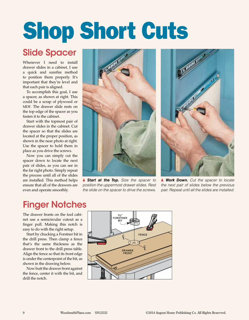
The drawer fronts on the tool cabi-net use a semicircular cutout as a finger pull. Making this notch is easy to do with the right setup.
Start by chucking a Forstner bit in the drill press. Then clamp a fence that’s the same thickness as the drawer front to the drill press table. Align the fence so that its front edge is under the centerpoint of the bit, as shown in the drawing below.
Now butt the drawer front against the fence, center it with the bit, and drill the notch.
CL
CL
FENCE
DRAWER FRONT
1!/2"FORSTNER
BIT
{ Start at the Top. Size the spacer to position the uppermost drawer slides. Rest the slide on the spacer to drive the screws.
{ Work Down. Cut the spacer to locate the next pair of slides below the previous pair. Repeat until all the slides are installed.
Whenever I need to install drawer slides in a cabinet, I use a quick and surefire method to position them properly. It’s important that they’re level and that each pair is aligned.
To accomplish this goal, I use a spacer, as shown at right. This could be a scrap of plywood or MDF. The drawer slide rests on the top edge of the spacer as you fasten it to the cabinet.
Start with the topmost pair of drawer slides in the cabinet. Cut the spacer so that the slides are located at the proper position, as shown in the near photo at right. Use the spacer to hold them in place as you drive the screws.
Now you can simply cut the spacer down to locate the next pair of slides, as you can see in the far right photo. Simply repeat the process until all of the slides are installed. This method helps ensure that all of the drawers are even and operate smoothly.
Finger Notches
Slide Spacer
Shop Short Cuts
10 WoodsmithPlans.com SN12532 ©2014 August Home Publishing Co. All Rights Reserved.
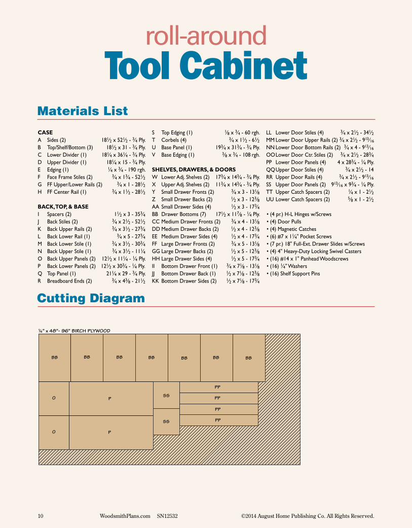
Materials List
roll-aroundTool Cabinet
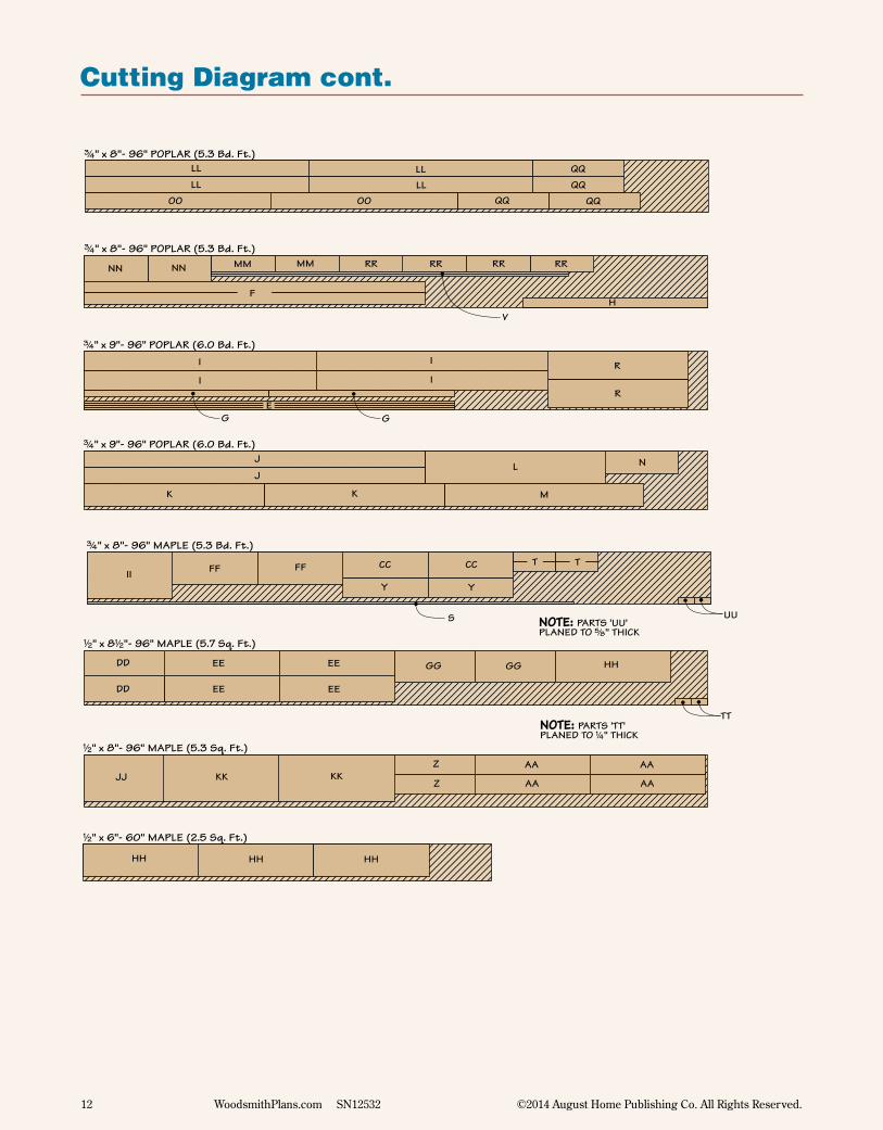
Cutting Diagram
NOTE: PARTS 'TT'PLANED TO !/4" THICK
BB
!/4" x 48"- 96" BIRCH PLYWOOD
BB BB BB BB BB BB
PP
PP
PP
PP
O
O
P
P
#/4" x 48"- 96" BIRCH PLYWOOD
Q
#/4" x 48"- 96" BIRCH PLYWOOD
U
B
C
D W W
A
A
BB
X
X
!/2" x 8!/2"- 96" MAPLE (5.7 Sq. Ft.)
DD
DD
EE
EE
GG GG
HHHH
#/4" x 8"- 96" POPLAR (5.3 Bd. Ft.)LL
LLLLLL
OO OO
QQQQ QQ
#/4" x 8"- 96" POPLAR (5.3 Bd. Ft.)
NN NN MMMM RR RR RR RR
V
F
#/4" x 8"- 96" MAPLE (5.3 Bd. Ft.)
II FF FF CC CC
Y Y
T T
S
#/4" x 9"- 96" POPLAR (6.0 Bd. Ft.)I
I I
I
G
H
E
R
R
#/4" x 9"- 96" POPLAR (6.0 Bd. Ft.)J
J
K K
L
M
N
!/2" x 8"- 96" MAPLE (5.3 Sq. Ft.)
JJ KK KKZ
Z
AA
AA
SS
SS
TT
UU
HH
HHEE
EE
!/2" x 6"- 60" MAPLE (2.5 Sq. Ft.)
NOTE: PARTS 'UU'PLANED TO %/8" THICK
AA
AA
G
CASEA Sides (2) 181⁄2 x 521⁄2 - 3⁄4 Ply.B Top/Shelf/Bottom (3) 181⁄2 x 31 - 3⁄4 Ply.C Lower Divider (1) 181⁄4 x 361⁄4 - 3⁄4 Ply.D Upper Divider (1) 181⁄4 x 15 - 3⁄4 Ply.E Edging (1) 1⁄4 x 3⁄4 - 190 rgh.F Face Frame Stiles (2) 3⁄4 x 13⁄4 - 521⁄2G FF Upper/Lower Rails (2) 3⁄4 x 1 - 281⁄2H FF Center Rail (1) 3⁄4 x 11⁄2 - 281⁄2
BACK, TOP, & BASEI Spacers (2) 11⁄2 x 3 - 353⁄4J Back Stiles (2) 3⁄4 x 21⁄2 - 521⁄2K Back Upper Rails (2) 3⁄4 x 31⁄2 - 273⁄4L Back Lower Rail (1) 3⁄4 x 5 - 273⁄4M Back Lower Stile (1) 3⁄4 x 31⁄2 - 303⁄4N Back Upper Stile (1) 3⁄4 x 31⁄2 - 111⁄4O Back Upper Panels (2) 121⁄2 x 111⁄4 - 1⁄4 Ply. P Back Lower Panels (2) 121⁄2 x 303⁄4 - 1⁄4 Ply.Q Top Panel (1) 211⁄4 x 29 - 3⁄4 Ply.R Breadboard Ends (2) 3⁄4 x 43⁄8 - 211⁄2
S Top Edging (1) 1⁄8 x 3⁄4 - 60 rgh.T Corbels (4) 3⁄4 x 11⁄2 - 61⁄2U Base Panel (1) 193⁄4 x 313⁄4 - 3⁄4 Ply.V Base Edging (1) 3⁄8 x 3⁄4 - 108 rgh.
SHELVES, DRAWERS, & DOORSW Lower Adj. Shelves (2) 173⁄4 x 143⁄4 - 3⁄4 Ply.X Upper Adj. Shelves (2) 113⁄4 x 143⁄4 - 3⁄4 Ply.Y Small Drawer Fronts (2) 3⁄4 x 3 - 131⁄8Z Small Drawer Backs (2) 1⁄2 x 3 - 123⁄8AA Small Drawer Sides (4) 1⁄2 x 3 - 173⁄4BB Drawer Bottoms (7) 171⁄2 x 117⁄8 - 1⁄4 Ply.CC Medium Drawer Fronts (2) 3⁄4 x 4 - 131⁄8DD Medium Drawer Backs (2) 1⁄2 x 4 - 123⁄8EE Medium Drawer Sides (4) 1⁄2 x 4 - 173⁄4FF Large Drawer Fronts (2) 3⁄4 x 5 - 131⁄8GG Large Drawer Backs (2) 1⁄2 x 5 - 123⁄8HH Large Drawer Sides (4) 1⁄2 x 5 - 173⁄4II Bottom Drawer Front (1) 3⁄4 x 71⁄8 - 131⁄8JJ Bottom Drawer Back (1) 1⁄2 x 71⁄8 - 123⁄8KK Bottom Drawer Sides (2) 1⁄2 x 71⁄8 - 173⁄4
LL Lower Door Stiles (4) 3⁄4 x 21⁄2 - 341⁄2MM Lower Door Upper Rails (2) 3⁄4 x 21⁄2 - 913⁄16
NN Lower Door Bottom Rails (2) 3⁄4 x 4 - 913⁄16
OO Lower Door Ctr. Stiles (2) 3⁄4 x 21⁄2 - 283⁄4PP Lower Door Panels (4) 4 x 283⁄4 - 1⁄4 Ply.QQ Upper Door Stiles (4) 3⁄4 x 21⁄2 - 14RR Upper Door Rails (4) 3⁄4 x 21⁄2 - 913⁄16
SS Upper Door Panels (2) 913⁄16 x 93⁄4 - 1⁄4 Ply.TT Upper Catch Spacers (2) 1⁄4 x 1 - 21⁄2UU Lower Catch Spacers (2) 5⁄8 x 1 - 21⁄2
• (4 pr.) H-L Hinges w/Screws• (4) Door Pulls• (4) Magnetic Catches• (6) #7 x 11⁄4" Pocket Screws• (7 pr.) 18" Full-Ext. Drawer Slides w/Screws• (4) 4" Heavy-Duty Locking Swivel Casters • (16) #14 x 1" Panhead Woodscrews• (16) 1⁄4" Washers • (16) Shelf Support Pins
11 WoodsmithPlans.com SN12532 ©2014 August Home Publishing Co. All Rights Reserved.
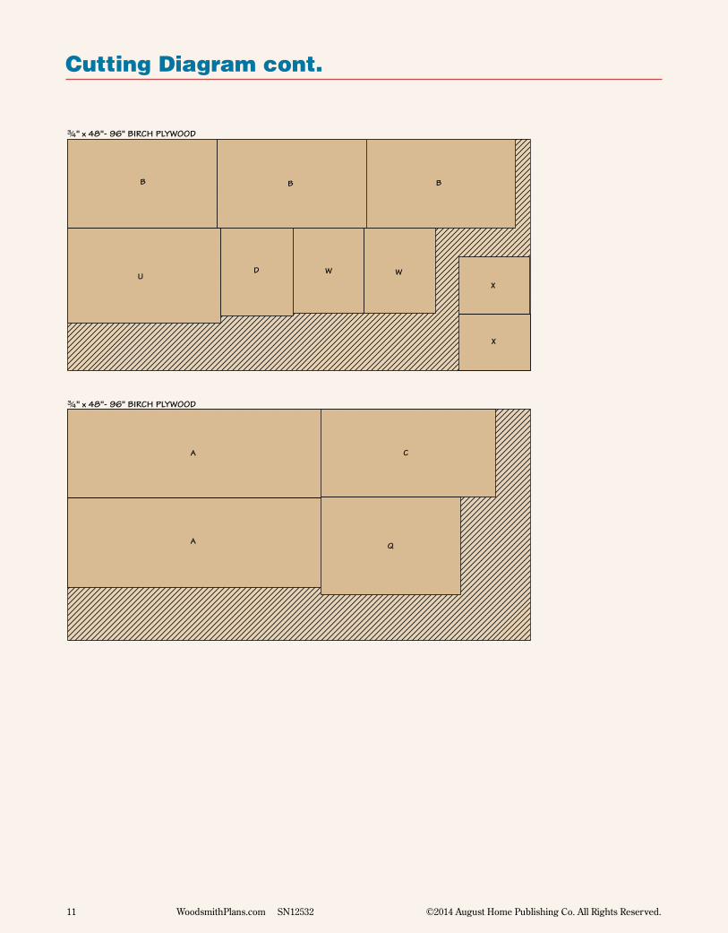
Cutting Diagram cont.
NOTE: PARTS 'TT'PLANED TO !/4" THICK
BB
!/4" x 48"- 96" BIRCH PLYWOOD
BB BB BB BB BB BB
PP
PP
PP
PP
O
O
P
P
#/4" x 48"- 96" BIRCH PLYWOOD
Q
#/4" x 48"- 96" BIRCH PLYWOOD
U
B
C
D W W
A
A
BB
X
X
!/2" x 8!/2"- 96" MAPLE (5.7 Sq. Ft.)
DD
DD
EE
EE
GG GG
HHHH
#/4" x 8"- 96" POPLAR (5.3 Bd. Ft.)LL
LLLLLL
OO OO
QQQQ QQ
#/4" x 8"- 96" POPLAR (5.3 Bd. Ft.)
NN NN MMMM RR RR RR RR
V
F
#/4" x 8"- 96" MAPLE (5.3 Bd. Ft.)
II FF FF CC CC
Y Y
T T
S
#/4" x 9"- 96" POPLAR (6.0 Bd. Ft.)I
I I
I
G
H
E
R
R
#/4" x 9"- 96" POPLAR (6.0 Bd. Ft.)J
J
K K
L
M
N
!/2" x 8"- 96" MAPLE (5.3 Sq. Ft.)
JJ KK KKZ
Z
AA
AA
SS
SS
TT
UU
HH
HHEE
EE
!/2" x 6"- 60" MAPLE (2.5 Sq. Ft.)
NOTE: PARTS 'UU'PLANED TO %/8" THICK
AA
AA
G
12 WoodsmithPlans.com SN12532 ©2014 August Home Publishing Co. All Rights Reserved.
Cutting Diagram cont.
NOTE: PARTS 'TT'PLANED TO !/4" THICK
BB
!/4" x 48"- 96" BIRCH PLYWOOD
BB BB BB BB BB BB
PP
PP
PP
PP
O
O
P
P
#/4" x 48"- 96" BIRCH PLYWOOD
Q
#/4" x 48"- 96" BIRCH PLYWOOD
U
B
C
D W W
A
A
BB
X
X
!/2" x 8!/2"- 96" MAPLE (5.7 Sq. Ft.)
DD
DD
EE
EE
GG GG
HHHH
#/4" x 8"- 96" POPLAR (5.3 Bd. Ft.)LL
LLLLLL
OO OO
QQQQ QQ
#/4" x 8"- 96" POPLAR (5.3 Bd. Ft.)
NN NN MMMM RR RR RR RR
V
F
#/4" x 8"- 96" MAPLE (5.3 Bd. Ft.)
II FF FF CC CC
Y Y
T T
S
#/4" x 9"- 96" POPLAR (6.0 Bd. Ft.)I
I I
I
G
H
E
R
R
#/4" x 9"- 96" POPLAR (6.0 Bd. Ft.)J
J
K K
L
M
N
!/2" x 8"- 96" MAPLE (5.3 Sq. Ft.)
JJ KK KKZ
Z
AA
AA
SS
SS
TT
UU
HH
HHEE
EE
!/2" x 6"- 60" MAPLE (2.5 Sq. Ft.)
NOTE: PARTS 'UU'PLANED TO %/8" THICK
AA
AA
G
Woodsmith Store800-444-7527
Rockler800-279-4441rockler.com
General Finishes800-783-6050
generalfinishes.com
Horton Brasses800-754-9127
horton-brasses.com
Lee Valley800-871-8158leevalley.com
MAIL ORDER
SOURCES
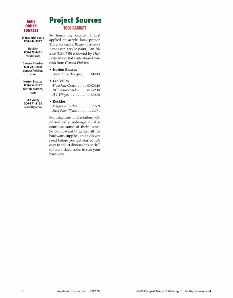
Project Sourcestool cabinet
To finish the cabinet, I first applied an acrylic latex primer. The color coat is Benjamin Moore’s Aura satin acrylic paint, Fair Isle Blue (CSP-715) followed by High Performance flat water-based var-nish from General Finishes.
•Horton BrassesDoor Pulls (Antique) . . . . .MS-13
•Lee Valley4” Locking Casters . . . . . 00K20.1018” Drawer Slides . . . . 02K42.18H-L Hinges . . . . . . . . . . .01X35.30
•RocklerMagnetic Catches . . . . . . . . 26559Shelf Pins (Black) . . . . . . . . 22781
Manufactures and retailers will periodically redesign or dis-continue some of their items. So you’ll want to gather all the hardware, supplies, and tools you need before you get started. It’s easy to adjust dimensions or drill different sized holes to suit your hardware.
13 WoodsmithPlans.com SN12532 ©2014 August Home Publishing Co. All Rights Reserved.


![eventguide.engineering.asu.edu · Web viewIf room has an outside window, be prepared to signal someone outside. Clothing on Fire: [Stop, Drop, Roll] Roll person around on floor to](https://img.pdfslide.net/doc/110x75/5b382bc47f8b9a600a8cf5eb/-web-viewif-room-has-an-outside-window-be-prepared-to-signal-someone-outside.jpg)


![Virtuoso: The Tool Cabinet and Workbench of Henry … The Tool Cabinet and Workbench of Henry O. Studley [ 66 ] Working our way around the open cabinet in a roughly clockwise manner](https://img.pdfslide.net/doc/110x75/5aa9c73a7f8b9a90188d4730/virtuoso-the-tool-cabinet-and-workbench-of-henry-the-tool-cabinet-and-workbench.jpg)