Embed Size (px)
Citation preview
78 I Renold Roller Chain Catalogue
Section 2Chain Installation & Maintenance

HEALTH AND SAFETY WARNING
The following precautions must be taken before disconnecting and removing a chain from a system prior to replacement.
1. Always isolate the power source from the drive or equipment.
2. Always wear safety glasses.
3. Always wear appropriate protective clothing, hats, gloves and safety shoes as warranted by the circumstances.
4. Always ensure tools are in good working condition and used in the proper manner.
5. Always loosen tensioning devices.
6. Always support the chain to avoid sudden unexpected movement of chain or components.
7. Never attempt to disconnect or reconnect a chain unless the chain construction is fully understood.
8. Always ensure that directions for the correct use of any tools are followed.
9. Never reuse individual components.
10. Never reuse a damaged chain or chain part.
N.B. Breach of these practices could result in serious injury or death.
Renold Roller Chain Catalogue I 79
80 I Renold Roller Chain Catalogue
Sect
ion
2
Chain Installation and MaintenanceIntroduction
Renold Chain has over 120 years’ experience in the operation and maintenance of transmission chain. Involvement with designers, manufacturers and users of all types of equipment has enabled Renold todevelop this definitive guide, designed to pass on the preferred methods of correct handling, adjustment, installation and maintenance of transmission chain drivesresulting in maximum chain life.
Should you require any further information,please contact our technical sales staff.
Equipment Needed
The breaking of chain can be achieved by usinga Renold Chain Extractor, these being:-
• 311015 for light industrial chains up to 0.5” pitch.
• 10101 for chains from 0.375” to 0.625” pitch
• 10102 for chains from 0.75” to 1.25” pitch
For joining any chain up to 2.5” pitch, a driftpunch will be required.
Erection of medium or heavy chain drivesrequires millwrighting equipment such as lifting tackle, slings, wedges, packing, etc.
Other useful equipment
Quantity of inner and outer links.
Straight edges and/or strong, fine line.
Spirit level.
Plumb line.
Selection of hammers, files, key blanks, etc.
Preparation
Check equipment to ensure that general transmission requirements are correct (e.g.flexible couplings, flywheel, means of driveadjustment).
Check condition and rigidity of the shafts and bearings, particularly if there has beenconsiderable previous service with an alternative method of transmission. Replace or rectify if necessary.
Driver and driven shafts should be checked to ensure they are level and parallel to eachother. This applies equally to the jockey shaft if present.
Use a spirit level and adjustable comparatorbar or micrometer between shafts at extremepoints on each side of the drive. Rectify anyparallelism error present and mark a permanentdatum line for the adjustable shaft.
Place sprockets or respective shafts in approximate alignment and fit the keys inaccordance with correct engineering practice.Do not finally secure keys at this stage.
Care must be taken with sprockets of splitdesign to ensure perfect abutting of the facesof each half. Proceed with the key fitting afterthe halves are finally bolted together, otherwisethe key can prevent correct assembly and subsequently result in malgearing.
It should be verified that key heads will notproject beyond the width of any chaincases.
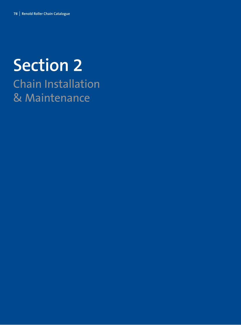
Checking Sprocket Alignment
Accurate alignment of shafts and sprockettooth faces provides a uniform distribution of load across the entire chain width and contributes substantially to maximum drive life.
Use a straight edge across the machined facesof the sprockets in several different positions,if possible, as a check against wobble. A nylonor similar line is a good substitute for a straightedge particularly on longer centre distances.
Should endwise “float” of shafts be present,make due allowance so that sprocket alignmentis correct at the mid position of “float”.
When alignment is correct within closest practical limits, drive the keys home and take a final check on sprocket alignment.
Renold Roller Chain Catalogue I 81
Sect
ion
2
Chain Installation and Maintenance
Important Note
Sprockets should always be designed to be asclose to the supporting bearings as possible.
Installation of Chain
Renold Chain should not be assembled on thesprockets until attention has been paid to:
1. Cleanliness of the sprocket teeth, particularly if debris of an abrasive nature(cement dust, weld spatter, etc.), has been prevalent whilst work was in progress.
2. Temporary positioning of the lower sectionof a chaincase if present. In restrictedspaces, manoeuvring of large sections is often simplified by using the spacesbetween shafts which will later be occupiedby the chain.
Ensure the chain is clean and free from debrisand place around the sprockets, observinginstructions where matched strands areinvolved. In chain of two or more strands, joining is most easily accomplished at the mid span of the drive, drawing the chain endstogether with a chain clamp or rope tackleblock. Ensure that the strength of the drawingtackle is sufficient to hold the chain. Chainweights are shown in the Renold catalogue.When inserting the joining link of multiplexchain, ensure the intermediate plates areassembled. Do not detach the drawing tackleuntil the link is completely assembled. Whenonly partially inserted through inner links, the
weight of the chain on release can “splay”unsupported bearing pins.
Adjust the chain using the datum mark mentioned in the preparation section to retain shaft parallelism.
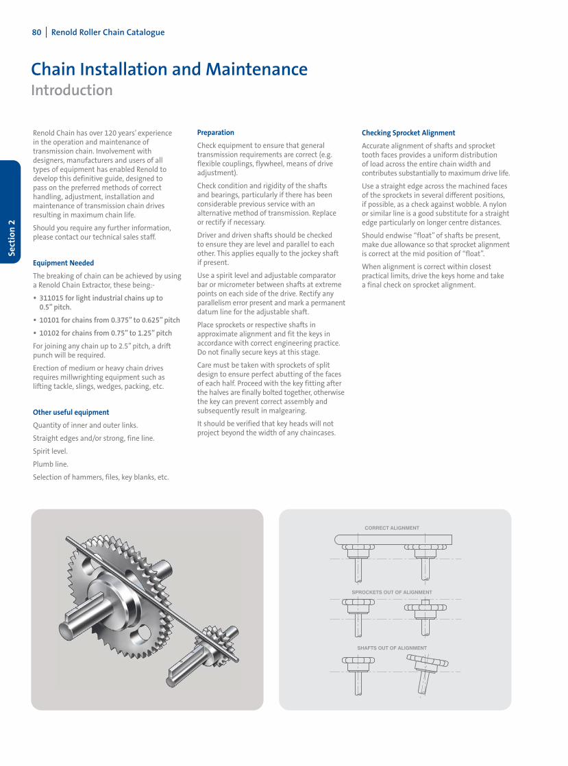
For a chain of average centre distance (30-50 x chain pitch) correct adjustment is when themid point of the longest span can be fullymoved by hand in accordance with dimension‘A’ shown in diagram one.
Chaincases
• Position the chaincase bottom sections with the shafts concentric in their cavities
• Manufacture suitable mountings and brackets to ensure rigidity
• Assemble the oil supply and return pipe system and the drive to the oil pump
• Assemble top section(s) of chaincase
• Fill the oil sump and check delivery to the chain
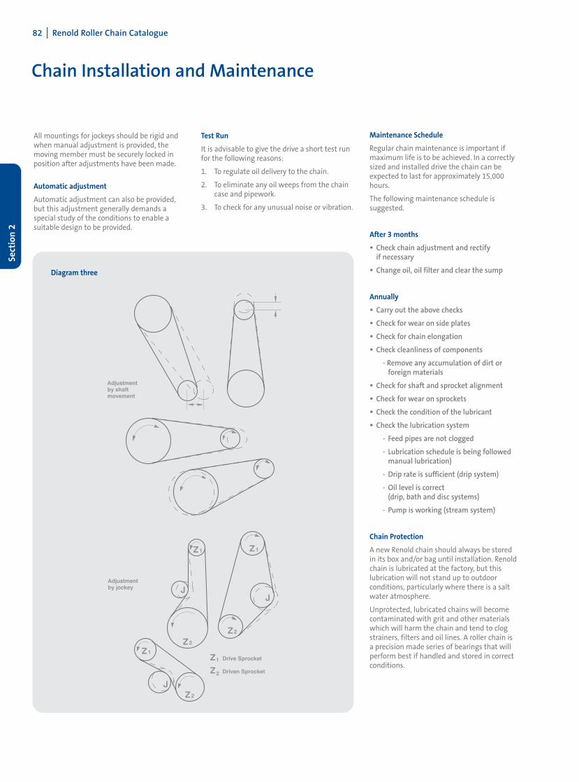
Chain Adjustment
To maximise chain life, some form of chainlength adjustment must be provided, preferablyby moving one of the shafts. See diagramthree. If shaft movement is not possible, anadjustable jockey sprocket engaging with theunloaded strand of the chain is recommended.Generally, the jockey should have the samenumber of teeth as the driver sprocket andcare should be taken to ensure speed does not exceed the maximum ratings shown.
Diagram one Diagram two
The chain should be adjusted regularly so thatwith one strand tight the slack strand can bemoved a distance of 'A' at the mid point. Seediagram one, on this page.
To cater for any eccentricities of mounting, the adjustment of the chain should be triedthrough a complete revolution of the largesprocket.
Adjustment, as shown in these diagrams, isachieved either by the movement of one of the shafts or by use of the jockey sprocket. Theamount of the adjustment provided by eithermethod should be sufficient to take up chainwear amounting to two pitches or two percentelongation above nominal chain length,whichever is the smaller.
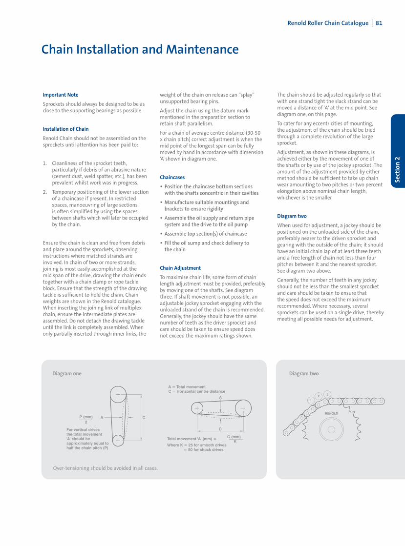
Diagram two
When used for adjustment, a jockey should bepositioned on the unloaded side of the chain,preferably nearer to the driven sprocket andgearing with the outside of the chain; it shouldhave an initial chain lap of at least three teethand a free length of chain not less than fourpitches between it and the nearest sprocket.See diagram two above.
Generally, the number of teeth in any jockeyshould not be less than the smallest sprocketand care should be taken to ensure that the speed does not exceed the maximum recommended. Where necessary, severalsprockets can be used on a single drive, therebymeeting all possible needs for adjustment.
Over-tensioning should be avoided in all cases.
82 I Renold Roller Chain Catalogue
Sect
ion
2
Chain Installation and Maintenance
All mountings for jockeys should be rigid andwhen manual adjustment is provided, themoving member must be securely locked inposition after adjustments have been made.
Automatic adjustment
Automatic adjustment can also be provided,but this adjustment generally demands a special study of the conditions to enable a suitable design to be provided.
Maintenance Schedule
Regular chain maintenance is important ifmaximum life is to be achieved. In a correctlysized and installed drive the chain can beexpected to last for approximately 15,000hours.
The following maintenance schedule is suggested.
After 3 months
• Check chain adjustment and rectify if necessary
• Change oil, oil filter and clear the sump
Annually
• Carry out the above checks
• Check for wear on side plates
• Check for chain elongation
• Check cleanliness of components
- Remove any accumulation of dirt or foreign materials
• Check for shaft and sprocket alignment
• Check for wear on sprockets
• Check the condition of the lubricant
• Check the lubrication system
- Feed pipes are not clogged
- Lubrication schedule is being followed manual lubrication)
- Drip rate is sufficient (drip system)
- Oil level is correct(drip, bath and disc systems)
- Pump is working (stream system)
Chain Protection
A new Renold chain should always be stored in its box and/or bag until installation. Renoldchain is lubricated at the factory, but this lubrication will not stand up to outdoor conditions, particularly where there is a saltwater atmosphere.
Unprotected, lubricated chains will becomecontaminated with grit and other materialswhich will harm the chain and tend to clogstrainers, filters and oil lines. A roller chain is a precision made series of bearings that willperform best if handled and stored in correctconditions.
Test Run
It is advisable to give the drive a short test runfor the following reasons:
1. To regulate oil delivery to the chain.
2. To eliminate any oil weeps from the chaincase and pipework.
3. To check for any unusual noise or vibration.
Diagram three
Renold Roller Chain Catalogue I 83
Sect
ion
2
Chain Installation and Maintenance
Lubrication
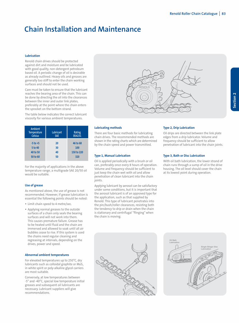
Renold chain drives should be protectedagainst dirt and moisture and be lubricatedwith good quality, non-detergent petroleumbased oil. A periodic change of oil is desirableas already outlined. Heavy oils and greases aregenerally too stiff to enter the chain workingsurfaces and should not be used.
Care must be taken to ensure that the lubricantreaches the bearing area of the chain. This canbe done by directing the oil into the clearancesbetween the inner and outer link plates, preferably at the point where the chain entersthe sprocket on the bottom strand.
The table below indicates the correct lubricantviscosity for various ambient temperatures.
AmbientTemperature Lubricant Rating
Celsius SAE BS4231
-5 to +5 20 46 to 685 to 40 30 100
40 to 50 40 150 to 22050 to 60 50 320
Lubricating methods
There are four basic methods for lubricatingchain drives. The recommended methods areshown in the rating charts which are determinedby the chain speed and power transmitted.
Type 1, Manual Lubrication
Oil is applied periodically with a brush or oil can, preferably once every 8 hours of operation.Volume and frequency should be sufficient tojust keep the chain wet with oil and allow penetration of clean lubricant into the chainjoints.
Applying lubricant by aerosol can be satisfactoryunder some conditions, but it is important thatthe aerosol lubricant is of an approved type forthe application, such as that supplied byRenold. This type of lubricant penetrates intothe pin/bush/roller clearances, resisting boththe tendency to drip or drain when the chain is stationary and centrifugal “flinging” whenthe chain is moving.
Type 2, Drip Lubrication
Oil drips are directed between the link plateedges from a drip lubricator. Volume and frequency should be sufficient to allow penetration of lubricant into the chain joints.
Type 3, Bath or Disc Lubrication
With oil bath lubrication, the lower strand ofchain runs through a sump of oil in the drivehousing. The oil level should cover the chain at its lowest point during operation.
For the majority of applications in the abovetemperature range, a multigrade SAE 20/50 oilwould be suitable.
Use of grease
As mentioned above, the use of grease is notrecommended. However, if grease lubrication isessential the following points should be noted:
• Limit chain speed to 4 metre/sec.
• Applying normal greases to the outside surfaces of a chain only seals the bearing surfaces and will not work into them. This causes premature failure. Grease has to be heated until fluid and the chain are immersed and allowed to soak until all air bubbles cease to rise. If this system is used the chains need regular cleaning and regreasing at intervals, depending on the drives, power and speed.
Abnormal ambient temperatures
For elevated temperatures up to 250°C, drylubricants such as colloidal graphite or MoS2
in white spirit or poly-alkaline glycol carriersare most suitable.
Conversely, at low temperatures between -5° and -40°C, special low temperature initialgreases and subsequent oil lubricants are necessary. Lubricant suppliers will give recommendations.
RENOLD
84 I Renold Roller Chain Catalogue
Sect
ion
2
Chain Installation and Maintenance
With slinger disc lubrication, an oil bath is usedbut the chain operates above the oil level. Adisc picks up oil from the sump and deposits it on the chain by means of deflection plates.When such discs are employed they should bedesigned to have peripheral speeds between180 to 2240 metre/min.
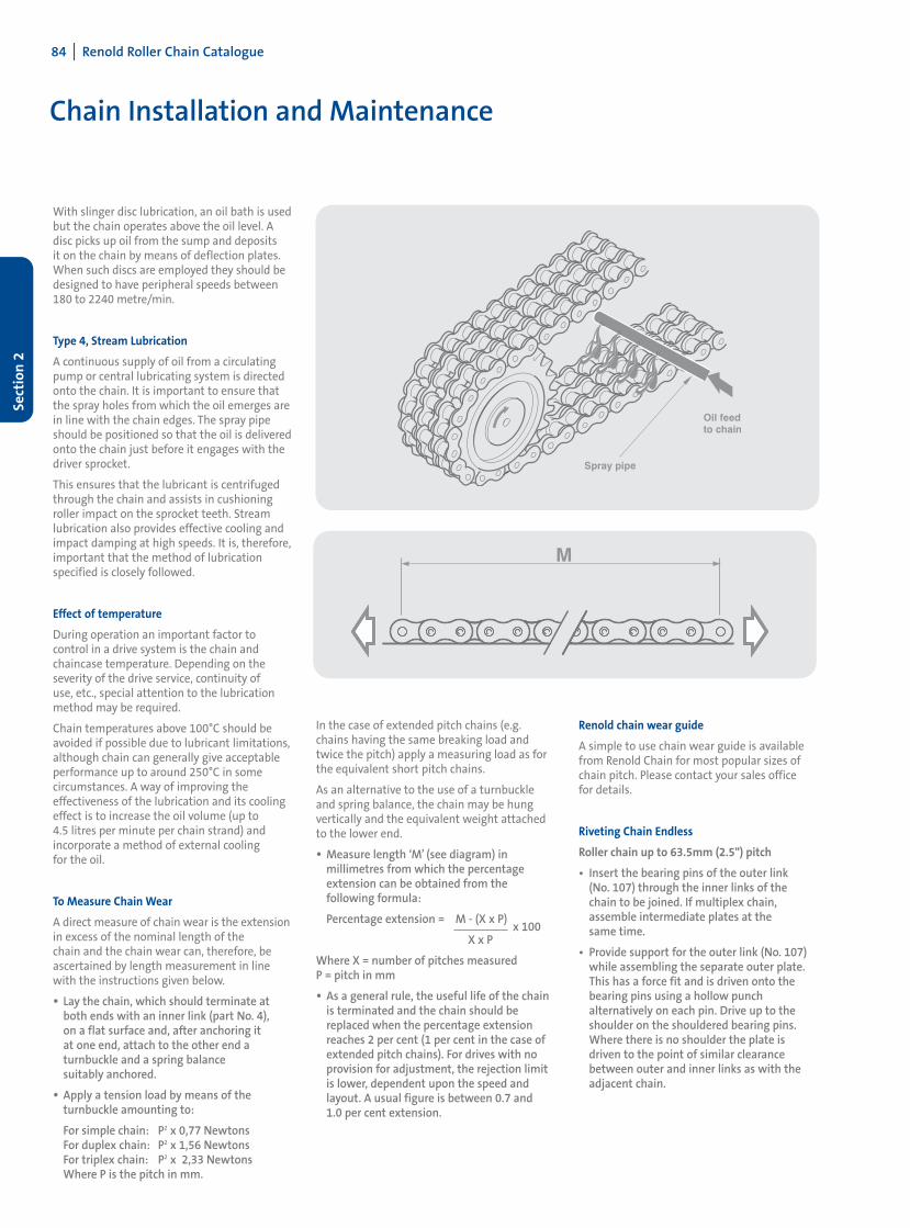
Type 4, Stream Lubrication
A continuous supply of oil from a circulatingpump or central lubricating system is directedonto the chain. It is important to ensure thatthe spray holes from which the oil emerges arein line with the chain edges. The spray pipeshould be positioned so that the oil is deliveredonto the chain just before it engages with thedriver sprocket.
This ensures that the lubricant is centrifugedthrough the chain and assists in cushioningroller impact on the sprocket teeth. Streamlubrication also provides effective cooling andimpact damping at high speeds. It is, therefore,important that the method of lubrication specified is closely followed.
Effect of temperature
During operation an important factor to control in a drive system is the chain andchaincase temperature. Depending on theseverity of the drive service, continuity of use, etc., special attention to the lubricationmethod may be required.
Chain temperatures above 100°C should beavoided if possible due to lubricant limitations,although chain can generally give acceptableperformance up to around 250°C in some circumstances. A way of improving theeffectiveness of the lubrication and its coolingeffect is to increase the oil volume (up to 4.5 litres per minute per chain strand) andincorporate a method of external cooling for the oil.
To Measure Chain Wear
A direct measure of chain wear is the extensionin excess of the nominal length of the chain and the chain wear can, therefore, beascertained by length measurement in linewith the instructions given below.
• Lay the chain, which should terminate at both ends with an inner link (part No. 4), on a flat surface and, after anchoring it at one end, attach to the other end a turnbuckle and a spring balance suitably anchored.
• Apply a tension load by means of the turnbuckle amounting to:
For simple chain: P2 x 0,77 NewtonsFor duplex chain: P2 x 1,56 NewtonsFor triplex chain: P2 x 2,33 NewtonsWhere P is the pitch in mm.
Renold chain wear guide
A simple to use chain wear guide is availablefrom Renold Chain for most popular sizes ofchain pitch. Please contact your sales office for details.
Riveting Chain Endless
Roller chain up to 63.5mm (2.5") pitch
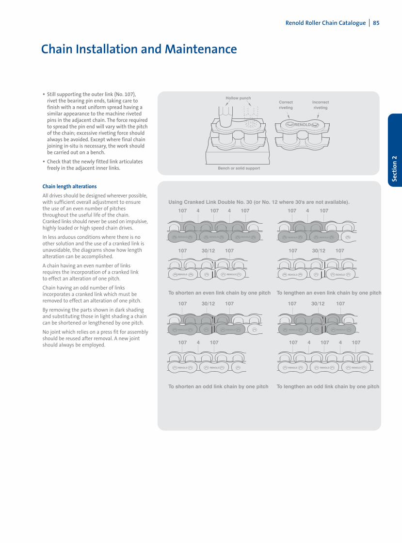
• Insert the bearing pins of the outer link (No. 107) through the inner links of the chain to be joined. If multiplex chain, assemble intermediate plates at the same time.
• Provide support for the outer link (No. 107) while assembling the separate outer plate. This has a force fit and is driven onto the bearing pins using a hollow punch alternatively on each pin. Drive up to the shoulder on the shouldered bearing pins. Where there is no shoulder the plate is driven to the point of similar clearance between outer and inner links as with the adjacent chain.
In the case of extended pitch chains (e.g.chains having the same breaking load andtwice the pitch) apply a measuring load as forthe equivalent short pitch chains.
As an alternative to the use of a turnbuckleand spring balance, the chain may be hung vertically and the equivalent weight attachedto the lower end.
• Measure length ‘M’ (see diagram) in millimetres from which the percentage extension can be obtained from the following formula:
Percentage extension = M - (X x P) x 100
X x P
Where X = number of pitches measuredP = pitch in mm
• As a general rule, the useful life of the chain is terminated and the chain should be replaced when the percentage extension reaches 2 per cent (1 per cent in the case of extended pitch chains). For drives with no provision for adjustment, the rejection limit is lower, dependent upon the speed and layout. A usual figure is between 0.7 and 1.0 per cent extension.
Renold Roller Chain Catalogue I 85
Sect
ion
2
Chain Installation and Maintenance
• Still supporting the outer link (No. 107), rivet the bearing pin ends, taking care to finish with a neat uniform spread having a similar appearance to the machine riveted pins in the adjacent chain. The force required to spread the pin end will vary with the pitch of the chain; excessive riveting force should always be avoided. Except where final chain joining in-situ is necessary, the work should be carried out on a bench.
• Check that the newly fitted link articulates freely in the adjacent inner links.
Chain length alterations
All drives should be designed wherever possible,with sufficient overall adjustment to ensurethe use of an even number of pitches throughout the useful life of the chain.Cranked links should never be used on impulsive,highly loaded or high speed chain drives.
In less arduous conditions where there is noother solution and the use of a cranked link isunavoidable, the diagrams show how lengthalteration can be accomplished.
A chain having an even number of linksrequires the incorporation of a cranked link to effect an alteration of one pitch.
Chain having an odd number of links incorporates a cranked link which must beremoved to effect an alteration of one pitch.
By removing the parts shown in dark shadingand substituting those in light shading a chaincan be shortened or lengthened by one pitch.
No joint which relies on a press fit for assemblyshould be reused after removal. A new jointshould always be employed.
86 I Renold Roller Chain Catalogue
Sect
ion
2
Chain Installation and Maintenance
Pairing and Matching Chains
Any application in which two or more strandsof transmission chain are required to operateside by side in a common drive or conveyingarrangement, may involve the need for eitherpairing or matching, and such applicationsgenerally fall into one of the following categories:
Length Matching for Conveying and Similar Applications
Wherever length matching of transmissionchain is necessary it is dealt with as follows:
• The chains are accurately measured in handling lengths between 3m to 8m as appropriate and then selected to provide a two (or more) strand drive having overall length uniformity within close limits. However, such length uniformity will not necessarily apply to any intermediate sections along the chains, but the actual length of all intermediate sections, both along and across the drive, will not vary more than our normal manufacturing limits. However, adapted transmission chains are usually manufactured to specific orders which are generally completed in one production run so that it is reasonable to assume that length differences of intermediate sections will be small.
• Chains are supplied in sets which are uniform in overall length within reasonably fine limits and will be within our normal manufacturing limits. It should be noted that chain sets supplied against different orders at different times may not have exactly the same lengths to those supplied originally, but will vary by no more than our normal tolerance of 0.0%, +0.15%.
Pitch Matching Transmission Drive Chains
Pitch matched chains are built up from shortersubsections (usually 300 to 600mm lengths)which are first measured and then graded forlength. All subsections in each grade are ofclosely similar length and those forming anyone group across the set of chains are selectedfrom the same length grade.
The requisite number of groups are then connected to form a pitch matched set ofchains, or alternatively, if this is too long forconvenient handling, a set of handling sectionsfor customer to assemble as a final set of pitchmatched chain. Suitable tags are fixed to thechains to ensure they are connected togetherin the correct sequence.
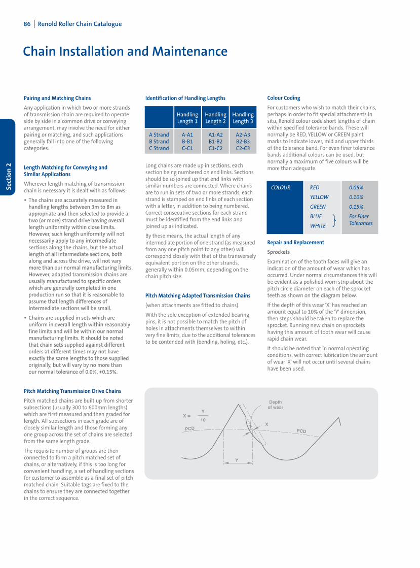
Identification of Handling Lengths
Long chains are made up in sections, each section being numbered on end links. Sectionsshould be so joined up that end links with similar numbers are connected. Where chainsare to run in sets of two or more strands, eachstrand is stamped on end links of each sectionwith a letter, in addition to being numbered.Correct consecutive sections for each strandmust be identified from the end links andjoined up as indicated.
By these means, the actual length of any intermediate portion of one strand (as measuredfrom any one pitch point to any other) will correspond closely with that of the transverselyequivalent portion on the other strands, generally within 0.05mm, depending on thechain pitch size.
Pitch Matching Adapted Transmission Chains
(when attachments are fitted to chains)
With the sole exception of extended bearingpins, it is not possible to match the pitch ofholes in attachments themselves to withinvery fine limits, due to the additional tolerancesto be contended with (bending, holing, etc.).
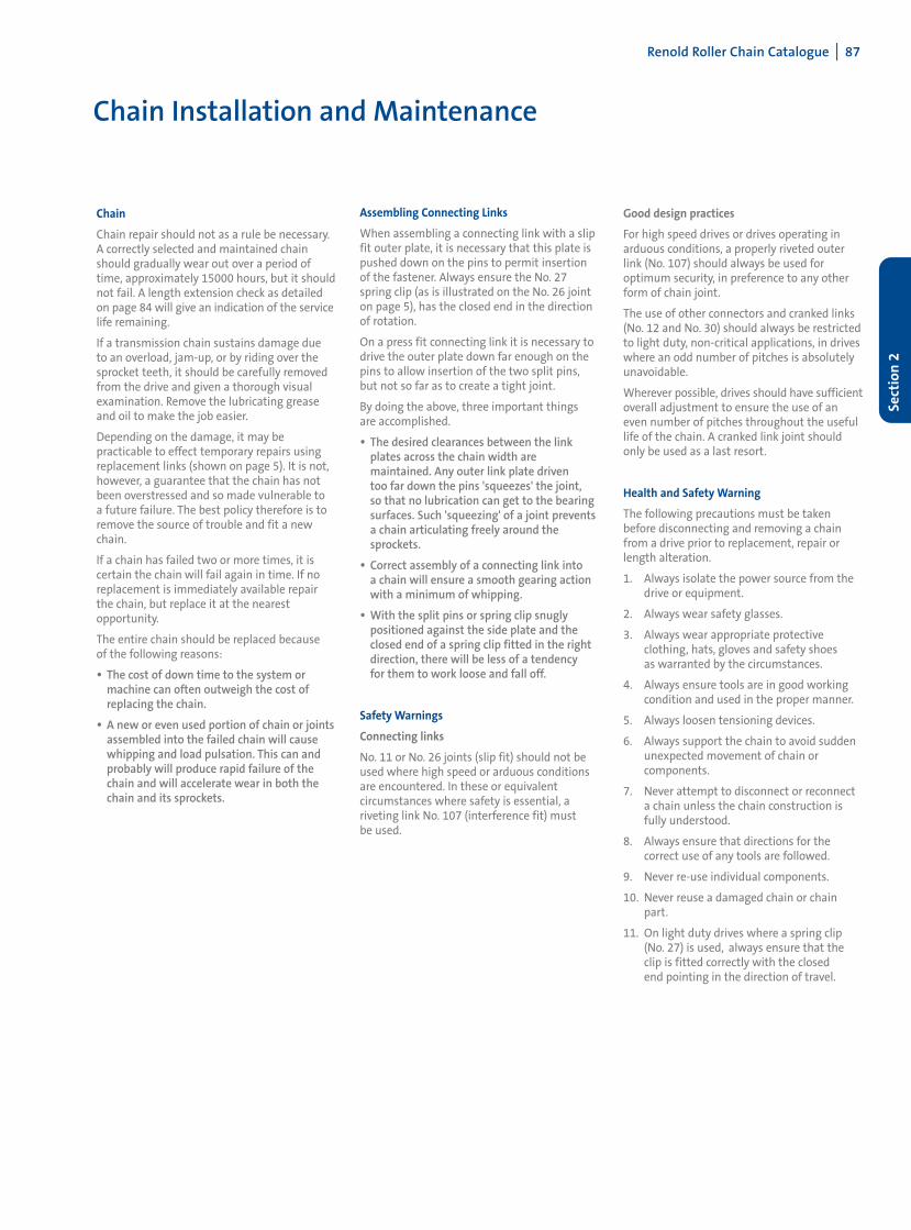
Colour Coding
For customers who wish to match their chains,perhaps in order to fit special attachments insitu, Renold colour code short lengths of chainwithin specified tolerance bands. These willnormally be RED, YELLOW or GREEN paintmarks to indicate lower, mid and upper thirdsof the tolerance band. For even finer tolerancebands additional colours can be used, but normally a maximum of five colours will bemore than adequate.
COLOUR RED 0.05%
YELLOW 0.10%
GREEN 0.15%
BLUE } For Finer
WHITE Tolerances
Repair and Replacement
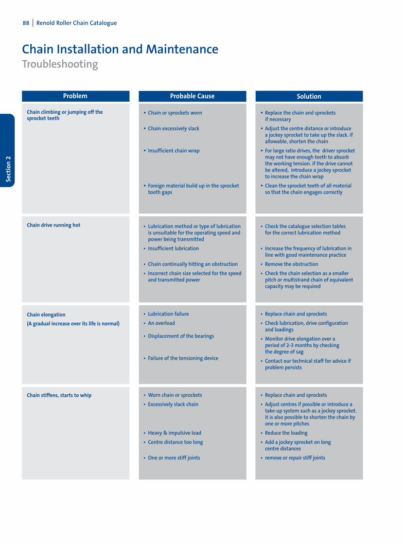
Sprockets
Examination of the tooth faces will give anindication of the amount of wear which hasoccurred. Under normal circumstances this willbe evident as a polished worn strip about thepitch circle diameter on each of the sprocketteeth as shown on the diagram below.
If the depth of this wear 'X' has reached anamount equal to 10% of the 'Y' dimension,then steps should be taken to replace thesprocket. Running new chain on sprockets having this amount of tooth wear will causerapid chain wear.
It should be noted that in normal operatingconditions, with correct lubrication the amountof wear 'X' will not occur until several chainshave been used.
Handling Handling HandlingLength 1 Length 2 Length 3
A Strand A-A1 A1-A2 A2-A3B Strand B-B1 B1-B2 B2-B3C Strand C-C1 C1-C2 C2-C3
Renold Roller Chain Catalogue I 87
Sect
ion
2
Chain Installation and Maintenance
Chain
Chain repair should not as a rule be necessary.A correctly selected and maintained chainshould gradually wear out over a period oftime, approximately 15000 hours, but it shouldnot fail. A length extension check as detailedon page 84 will give an indication of the servicelife remaining.
If a transmission chain sustains damage due to an overload, jam-up, or by riding over thesprocket teeth, it should be carefully removedfrom the drive and given a thorough visualexamination. Remove the lubricating greaseand oil to make the job easier.
Depending on the damage, it may be practicable to effect temporary repairs usingreplacement links (shown on page 5). It is not,however, a guarantee that the chain has notbeen overstressed and so made vulnerable to a future failure. The best policy therefore is toremove the source of trouble and fit a newchain.
If a chain has failed two or more times, it is certain the chain will fail again in time. If noreplacement is immediately available repairthe chain, but replace it at the nearest opportunity.
The entire chain should be replaced because of the following reasons:
• The cost of down time to the system or machine can often outweigh the cost of replacing the chain.
• A new or even used portion of chain or joints assembled into the failed chain will cause whipping and load pulsation. This can and probably will produce rapid failure of the chain and will accelerate wear in both the chain and its sprockets.
Assembling Connecting Links
When assembling a connecting link with a slipfit outer plate, it is necessary that this plate ispushed down on the pins to permit insertionof the fastener. Always ensure the No. 27spring clip (as is illustrated on the No. 26 jointon page 5), has the closed end in the directionof rotation.
On a press fit connecting link it is necessary todrive the outer plate down far enough on thepins to allow insertion of the two split pins,but not so far as to create a tight joint.
By doing the above, three important things are accomplished.
• The desired clearances between the link plates across the chain width are maintained. Any outer link plate driven too far down the pins 'squeezes' the joint, so that no lubrication can get to the bearing surfaces. Such 'squeezing' of a joint prevents a chain articulating freely around the sprockets.
• Correct assembly of a connecting link into a chain will ensure a smooth gearing action with a minimum of whipping.
• With the split pins or spring clip snugly positioned against the side plate and the closed end of a spring clip fitted in the right direction, there will be less of a tendency for them to work loose and fall off.
Safety Warnings
Connecting links
No. 11 or No. 26 joints (slip fit) should not beused where high speed or arduous conditionsare encountered. In these or equivalent circumstances where safety is essential, a riveting link No. 107 (interference fit) must be used.
Good design practices
For high speed drives or drives operating inarduous conditions, a properly riveted outerlink (No. 107) should always be used for optimum security, in preference to any otherform of chain joint.
The use of other connectors and cranked links(No. 12 and No. 30) should always be restrictedto light duty, non-critical applications, in driveswhere an odd number of pitches is absolutelyunavoidable.
Wherever possible, drives should have sufficientoverall adjustment to ensure the use of aneven number of pitches throughout the usefullife of the chain. A cranked link joint shouldonly be used as a last resort.
Health and Safety Warning
The following precautions must be takenbefore disconnecting and removing a chainfrom a drive prior to replacement, repair orlength alteration.
1. Always isolate the power source from thedrive or equipment.
2. Always wear safety glasses.
3. Always wear appropriate protective clothing, hats, gloves and safety shoes as warranted by the circumstances.
4. Always ensure tools are in good workingcondition and used in the proper manner.
5. Always loosen tensioning devices.
6. Always support the chain to avoid suddenunexpected movement of chain or components.
7. Never attempt to disconnect or reconnecta chain unless the chain construction isfully understood.
8. Always ensure that directions for the correct use of any tools are followed.
9. Never re-use individual components.
10. Never reuse a damaged chain or chainpart.
11. On light duty drives where a spring clip(No. 27) is used, always ensure that theclip is fitted correctly with the closed end pointing in the direction of travel.
88 I Renold Roller Chain Catalogue
Sect
ion
2
Chain Installation and MaintenanceTroubleshooting
Chain climbing or jumping off the sprocket teeth
Chain drive running hot
Chain elongation
(A gradual increase over its life is normal)
Chain stiffens, starts to whip
• Chain or sprockets worn
• Chain excessively slack
• Insufficient chain wrap
• Foreign material build up in the sprocket tooth gaps
• Lubrication method or type of lubrication is unsuitable for the operating speed and power being transmitted
• Insufficient lubrication
• Chain continually hitting an obstruction
• Incorrect chain size selected for the speed and transmitted power
• Lubrication failure
• An overload
• Displacement of the bearings
• Failure of the tensioning device
• Worn chain or sprockets
• Excessively slack chain
• Heavy & impulsive load
• Centre distance too long
• One or more stiff joints
• Replace the chain and sprockets if necessary
• Adjust the centre distance or introduce a jockey sprocket to take up the slack. if allowable, shorten the chain
• For large ratio drives, the driver sprocket may not have enough teeth to absorb the working tension. if the drive cannot be altered, introduce a jockey sprocket to increase the chain wrap
• Clean the sprocket teeth of all material so that the chain engages correctly
• Check the catalogue selection tables for the correct lubrication method
• Increase the frequency of lubrication in line with good maintenance practice
• Remove the obstruction
• Check the chain selection as a smaller pitch or multistrand chain of equivalent capacity may be required
• Replace chain and sprockets
• Check lubrication, drive configuration and loadings
• Monitor drive elongation over a period of 2-3 months by checking the degree of sag
• Contact our technical staff for advice if problem persists
• Replace chain and sprockets
• Adjust centres if possible or introduce a take-up system such as a jockey sprocket.it is also possible to shorten the chain by one or more pitches
• Reduce the loading
• Add a jockey sprocket on long centre distances
• remove or repair stiff joints
Problem Probable Cause Solution
Renold Roller Chain Catalogue I 89
Sect
ion
2
Chain Installation and MaintenanceTroubleshooting
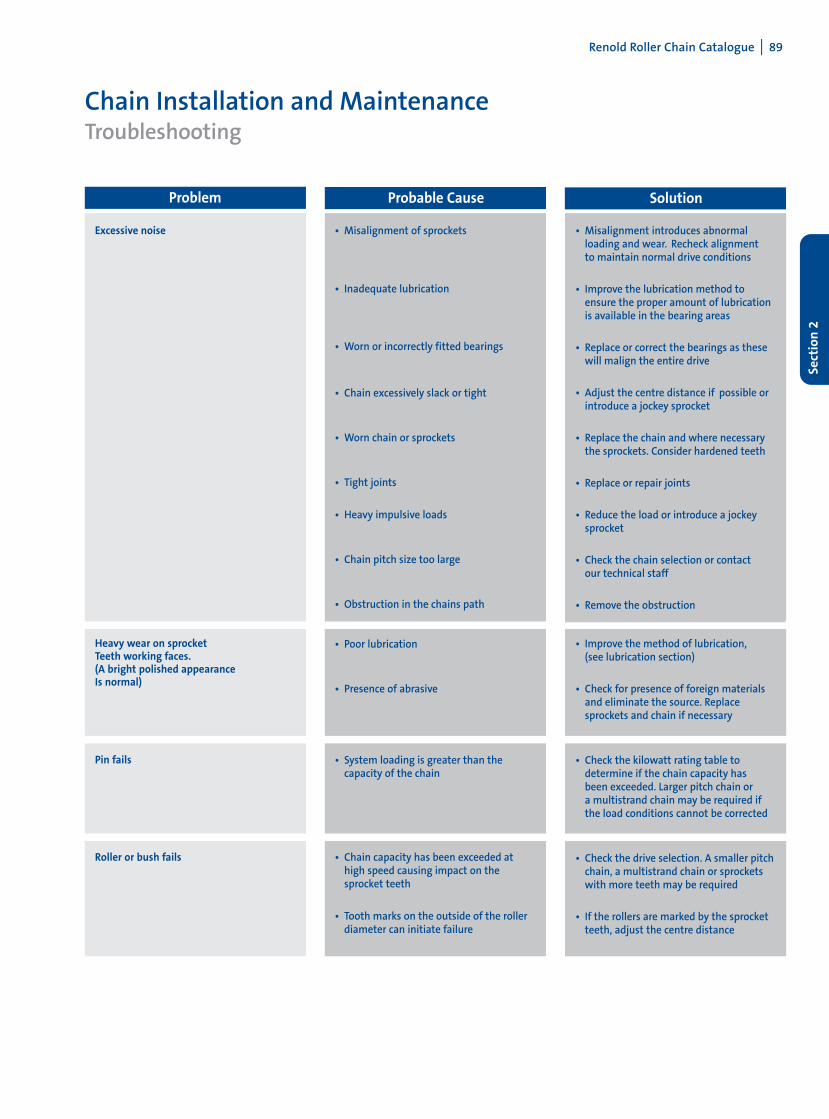
Excessive noise
Heavy wear on sprocketTeeth working faces. (A bright polished appearanceIs normal)
Pin fails
Roller or bush fails
• Misalignment of sprockets
• Inadequate lubrication
• Worn or incorrectly fitted bearings
• Chain excessively slack or tight
• Worn chain or sprockets
• Tight joints
• Heavy impulsive loads
• Chain pitch size too large
• Obstruction in the chains path
• Poor lubrication
• Presence of abrasive
• System loading is greater than the capacity of the chain
• Chain capacity has been exceeded at high speed causing impact on the sprocket teeth
• Tooth marks on the outside of the roller diameter can initiate failure
• Misalignment introduces abnormal loading and wear. Recheck alignment to maintain normal drive conditions
• Improve the lubrication method to ensure the proper amount of lubrication is available in the bearing areas
• Replace or correct the bearings as these will malign the entire drive
• Adjust the centre distance if possible or introduce a jockey sprocket
• Replace the chain and where necessary the sprockets. Consider hardened teeth
• Replace or repair joints
• Reduce the load or introduce a jockey sprocket
• Check the chain selection or contact our technical staff
• Remove the obstruction
• Improve the method of lubrication, (see lubrication section)
• Check for presence of foreign materials and eliminate the source. Replace sprockets and chain if necessary
• Check the kilowatt rating table to determine if the chain capacity has been exceeded. Larger pitch chain or a multistrand chain may be required if the load conditions cannot be corrected
• Check the drive selection. A smaller pitch chain, a multistrand chain or sprockets with more teeth may be required
• If the rollers are marked by the sprocket teeth, adjust the centre distance
Problem Probable Cause Solution
90 I Renold Roller Chain Catalogue
Sect
ion
2
Chain Installation and MaintenanceTroubleshooting
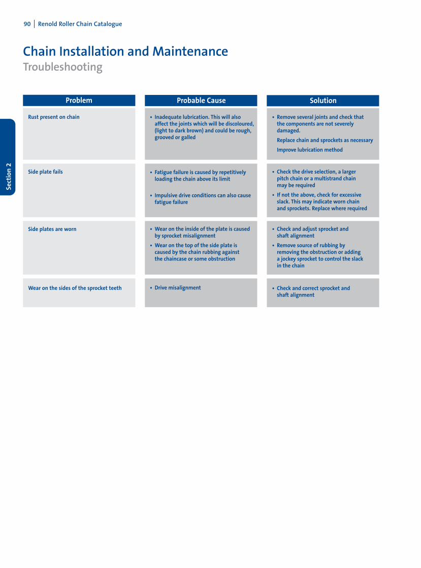
Rust present on chain
Side plate fails
Side plates are worn
Wear on the sides of the sprocket teeth
• Inadequate lubrication. This will also affect the joints which will be discoloured,(light to dark brown) and could be rough, grooved or galled
• Fatigue failure is caused by repetitively loading the chain above its limit
• Impulsive drive conditions can also cause fatigue failure
• Wear on the inside of the plate is caused by sprocket misalignment
• Wear on the top of the side plate is caused by the chain rubbing against the chaincase or some obstruction
• Drive misalignment
• Remove several joints and check that the components are not severely damaged.
Replace chain and sprockets as necessary
Improve lubrication method
• Check the drive selection, a larger pitch chain or a multistrand chain may be required
• If not the above, check for excessive slack. This may indicate worn chain and sprockets. Replace where required
• Check and adjust sprocket and shaft alignment
• Remove source of rubbing by removing the obstruction or adding a jockey sprocket to control the slack in the chain
• Check and correct sprocket and shaft alignment
Problem Probable Cause Solution