Embed Size (px)
Citation preview
Roller Garage Door Installation Manual
www.aluroll.co.uk
CLASSIC, COMPACT & ELITE

2. Important Information
3. Product Description3.1. Assembly Parts3.2. General Assembly Drawing3.3. Technical Data
4. Installation Instructions4.1. Preparing for Installation4.2. Preparing the Guide Channels4.3. Assembly of the Framework4.3.1. Preparing the Motor and Backbox4.3.2. Fixing the Guide Channels4.3.3. Fixing Steel Endplates4.3.4. Fixing Aluminium Endplates4.4. Setting Up the Control Panel4.4.1. Use of Control Panel Instructions4.4.2. Setting the ‘Closed’ Position of the Motor4.4.3. Find the ‘Closed Limit’ : Somfy Motor4.4.4. Find the ‘Closed Limit’ : Screw type 4.5. Installation of Winding Handle Override4.5.1. Standard Internal Override4.5.2. External High Level Override4.5.3. External Low Level Override4.6. Installation of Curtain4.7. Programming the Motor4.7.1. Installation of Somfy Motor4.7.2. Installation of Econom / Elero Motor4.8. Override Lock (Optional)4.9. Completing the Installation
5. Dismantling6. Manufacturer’s Declaration7. Manufacturer’s Warranty8. Service History 9. Declaration of Conformity
1. Contents
Please follow the installation instructions carefully. This booklet should be left with the door for future reference. Aluroll reserves the right to change technical details at its own discretion.
2

According to EN 12433-1 Feb. 2000 (Sect 2.1) a door is an ‘installation for closing an opening envisaged for letting through vehicles and people’. Our doors are solely designed for this purpose. No liability can be assumed for malfunctions arising from improper use (e.g. lifting people or objects).
CautionDoor manufacturer warranty ceases to apply should mounting not be carried out properly. Mounting is only to be carried out by suitably qualified skilled personnel. To avoid installation errors and damage to the door, it is vital that work proceeds on the basis of the mounting instructions of this manual. Since these mounting instructions contain vital information on testing and maintenance work, they are to be handed over to the user for reference purposes.
All mounting and dismantling work is to be carried out in keeping with the BS EN 12635 directives.
Only genuine replacement parts are to be used. The manufacturer’s declaration of conformity ceases to apply if this is not the case.
Maintenance InstructionsThe safety requirements for operating power-operated doors and gates are laid down in EN12453 and EN12445 standards. Maintenance and care covers a visual and functional testing of the curtain, driver, control unit, and all fastening points (motor fastening profile, brackets, bearings, guide rails). It must be carried out once per year. Failure to do so can void warranty.
All door components are to be examined as to fault-free and smooth operation. If necessary, they are to be cleaned, greased and repaired to ensure fault-free and safe functioning of the door system. Please refer to the attached description of the door control in question and/or driver operating instruction for troubleshooting any electrical malfunctioning.
SurfaceThe roll-formed Aluroll roller door profiles consist of stove-enamelled aluminium strips. The coating is applied to specially pre-treated aluminium strips in a double-sided coil coating process. The Aluroll extruded roller door profiles are powder-coated and stove enamelled.
CareDespite the high-grade coating, dirt and sand particles can result in colour abrasion over time. The reduce this or at least to keep it down, Aluroll recommends using plenty of water for regular cleaning of the roller door curtain (at least 4x per year). On no account are corrosive chemical cleaning agents to be used. A gentle household cleaner can be used to remove caked-on dirt.
Fixing MethodsThe specialist company charged with installing must adapt the fixing material for taking up loads to the fixing type and the specific building founding. As particular attention is to be paid to the fixing methods with roller doors, Aluroll recommends contacting the specialist trade for questions on specific solutions.
Electrical WorkElectrical work is only to be carried out by a qualified electrician when the equipment is shut down.
FrostMinus temperatures and freezing precipitation can cause the roller door profiles to freeze together or onto the base plate. Under conditions such as these, Aluroll recommends keeping the doors in view when opening them. If the ‘Up’ movement is impaired, the door is to be immediately stopped to prevent any damage occurring. Only when the ice on the roller door curtain has melted is the door to be operated.
Wind Resistance ClassesNote is to be taken of EN 13241-1 for the wind resistance classes recommended for the intended uses.
2. Important Information
3

3. Product Description
3.1. Assembly Parts
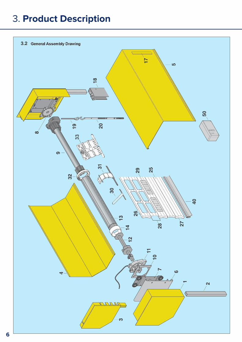
Parts for Construction1. Steel end-plates2. Pegs for steel plates3. Aluminium end-plates4. Roll-formed lid5. Roll-formed back-box6. Rolling console7. Moving plate8. Bracket for motor9. Tubular motor and drive wheels
10. Plate for safety brake
10. Safety brake11. Shaft bolt for 70 Oct shaft12. Steel shaft, 70mm Oct13. Adapter ring (for 70 Oct)14. Shaft bolt for 125mm shaft15. 125mm Fluted shaft16. PVC roll-guard17. Guide channels18. Eyelet for override19. Override handle
4
3. Product Description
3.1. Assembly Parts
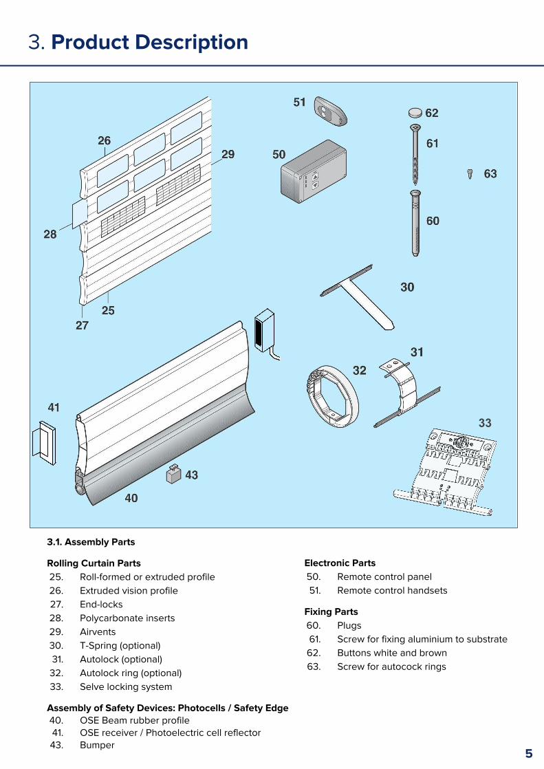
Rolling Curtain Parts25. Roll-formed or extruded profile26. Extruded vision profile27. End-locks28. Polycarbonate inserts29. Airvents30. T-Spring (optional)31. Autolock (optional)32. Autolock ring (optional)33. Selve locking system
Assembly of Safety Devices: Photocells / Safety Edge40. OSE Beam rubber profile41. OSE receiver / Photoelectric cell reflector43. Bumper
Electronic Parts50. Remote control panel51. Remote control handsets
Fixing Parts60. Plugs61. Screw for fixing aluminium to substrate62. Buttons white and brown63. Screw for autocock rings
5
33
3. Product Description
6
33

3. Product Description
3.3. Technical Data
1. Description: Roller Garage Door Type:
ID No.: Year: Dispatched on:
Manufacturer: Aluroll Ltd, Unit 12, Artillery Business Park, Oswestry, Shropshire, SY11 4AD
Installation address and installer:
2. Curtain
Dimensions: Material:
Weight: kg
Slat type:
3. Drive
Manufacturer:
Somfy Ltd, Moorfield Road, Yeadon, West Yorkshire, LS19 7BN
Elero UK Ltd, Foundry Lane, Halebank, Widnes, Cheshire, WA8 8TZ
Model:
Power: kW
Acceleration: min-1
Voltage: V
4. Operation type (e.g., keyswitch, remote control, etc.):
5. Fall prevention device Device type: Safety brake Manufacturer: Timmer, Link Controls Ltd
Model: TA 0-RD/Z Year: Max rotation: 147Nm 22min-1
Model: TA 1 / 2 – RD Year: Max rotation: 796 Nm 22min-1
Other remarks:
6. Modifications:
7
4. Installation Instructions
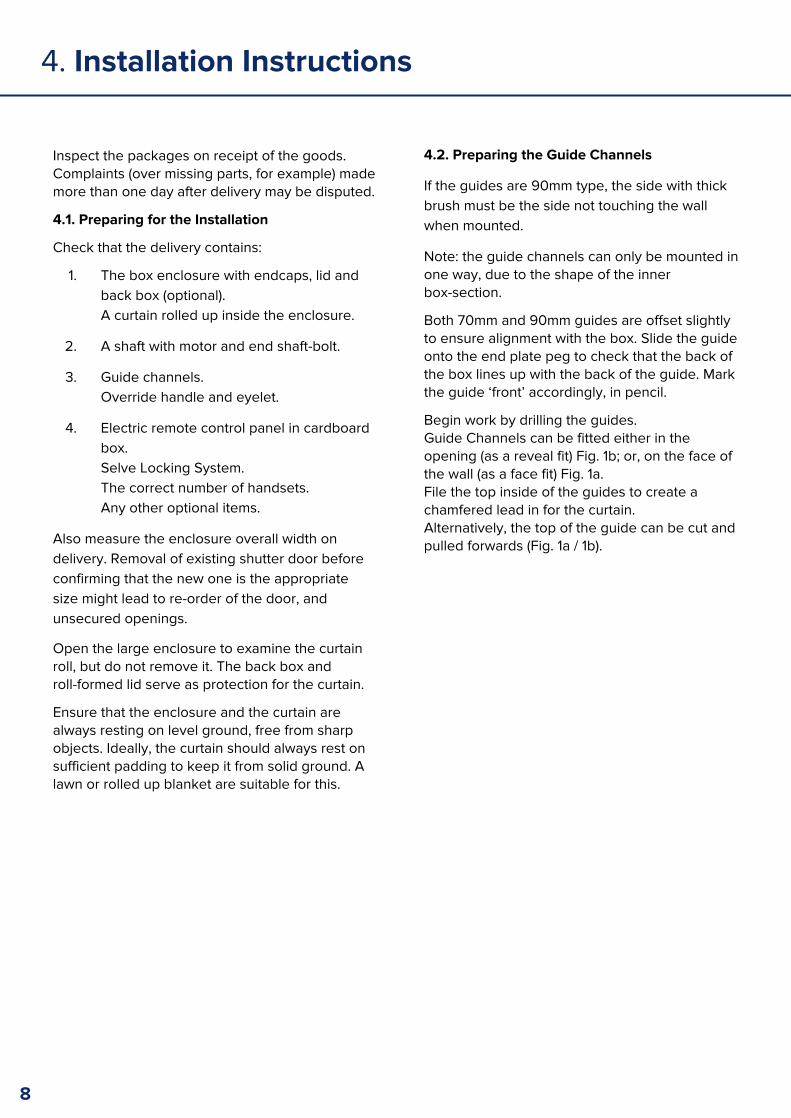
Inspect the packages on receipt of the goods. Complaints (over missing parts, for example) made more than one day after delivery may be disputed.
4.1. Preparing for the Installation
Check that the delivery contains:
1. The box enclosure with endcaps, lid and back box (optional).A curtain rolled up inside the enclosure.
2. A shaft with motor and end shaft-bolt.
3. Guide channels.Override handle and eyelet.
4. Electric remote control panel in cardboard box.Selve Locking System.The correct number of handsets.Any other optional items.
Also measure the enclosure overall width on delivery. Removal of existing shutter door before confirming that the new one is the appropriate size might lead to re-order of the door, and unsecured openings.
Open the large enclosure to examine the curtain roll, but do not remove it. The back box and roll-formed lid serve as protection for the curtain.
Ensure that the enclosure and the curtain are always resting on level ground, free from sharp objects. Ideally, the curtain should always rest on sufficient padding to keep it from solid ground. A lawn or rolled up blanket are suitable for this.
4.2. Preparing the Guide Channels
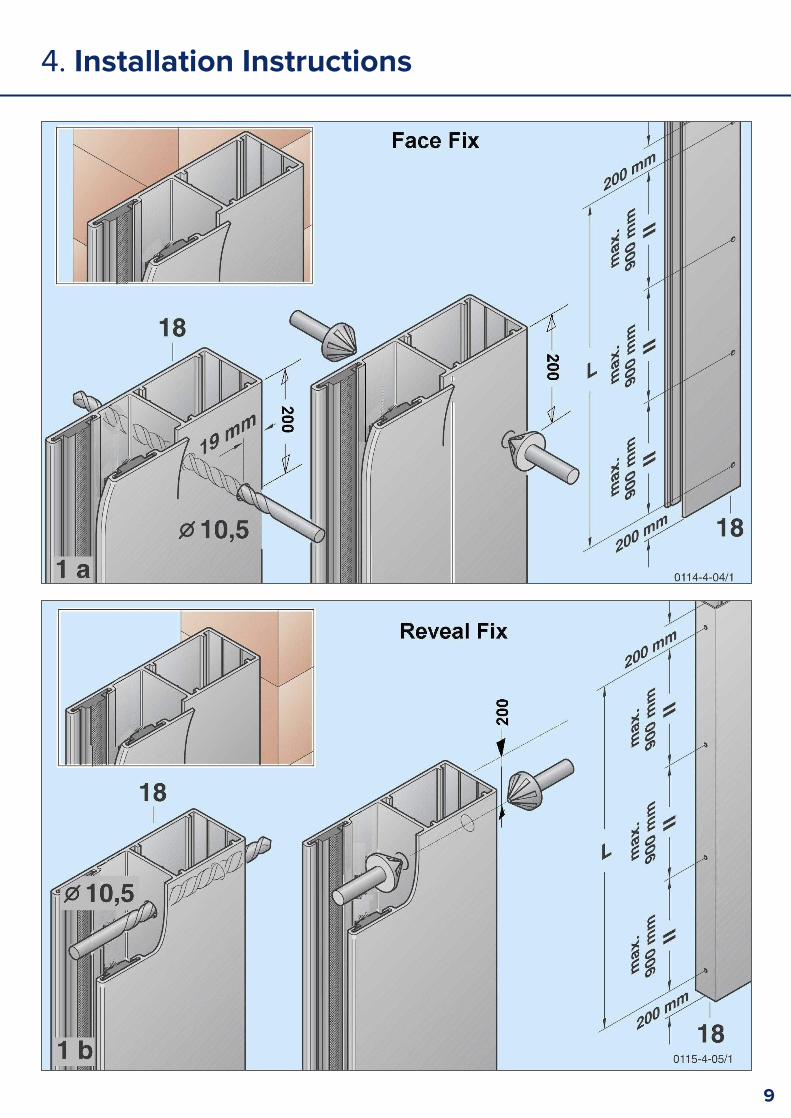
If the guides are 90mm type, the side with thick brush must be the side not touching the wall when mounted.
Note: the guide channels can only be mounted in one way, due to the shape of the inner box-section.
Both 70mm and 90mm guides are offset slightly to ensure alignment with the box. Slide the guide onto the end plate peg to check that the back of the box lines up with the back of the guide. Mark the guide ‘front’ accordingly, in pencil.
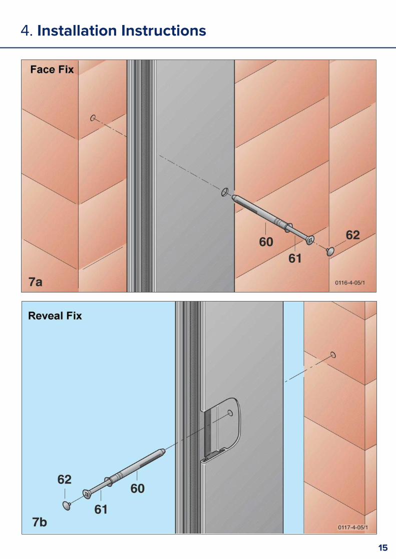
Begin work by drilling the guides. Guide Channels can be fitted either in the opening (as a reveal fit) Fig. 1b; or, on the face of the wall (as a face fit) Fig. 1a. File the top inside of the guides to create a chamfered lead in for the curtain. Alternatively, the top of the guide can be cut and pulled forwards (Fig. 1a / 1b).
8
4. Installation Instructions
9

4. Installation Instructions
4.3. Assembly of the Framework
If any fixings are in place to hold the lid to the back box, remove them (1), and lift the lid up and off (2). Place it to one side.
Lay the other roller curtain to one side and place the enclosure before the masonry opening so that work on the guides and enclosure can go ahead without problems.
When working with or moving the back box and guides, ensure that the parts are resting on a protective under layer or an even ground without sharp edges. A garden lawn is ideal.
Before fixing the guides and box over the opening, the motor barrel assembly must be installed:
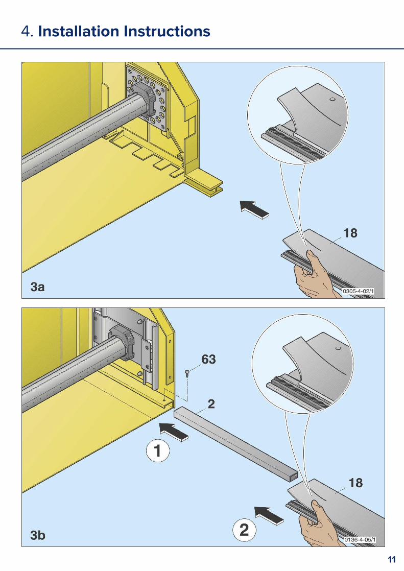
Slot the guide channels into the endplate pegs (Fig. 3). If steel endplates and pegs are being used, the pegs should be fixed in place with a screw or rivet (Fig. 3b).
4.3.1 Preparing the Motor and Back Box
The motor barrel is held in place by a captive bearing on the non-drive end, and a mounting plate on the drive end. The non-drive end of the barrel has an adjustable shaft held in place with an Allen bolt. With a 6mm Allen key, loosen the Allen bolt allowing the shaft to slide in and out of the motor barrel (Fig. 2.1.). Using the two counter-sunk nuts and bolts supplied, fit the barrel into position, making sure that the manual override position on the motor is at the required point, limit switches are visible, and that the motor is fitted to the correct side of the enclosure. (Figs. 3a & 3b are Right Hand motor installations.)
When you are happy that the motor barrel is installed in the correct way, tighten the motor plate and fully extend the sliding shaft into the free bearing at the non-drive end. Lock the shaft with an allen key.
Note: Do not operate the motor at this stage!
10
2.1
4. Installation Instructions
11
4. Installation Instructions
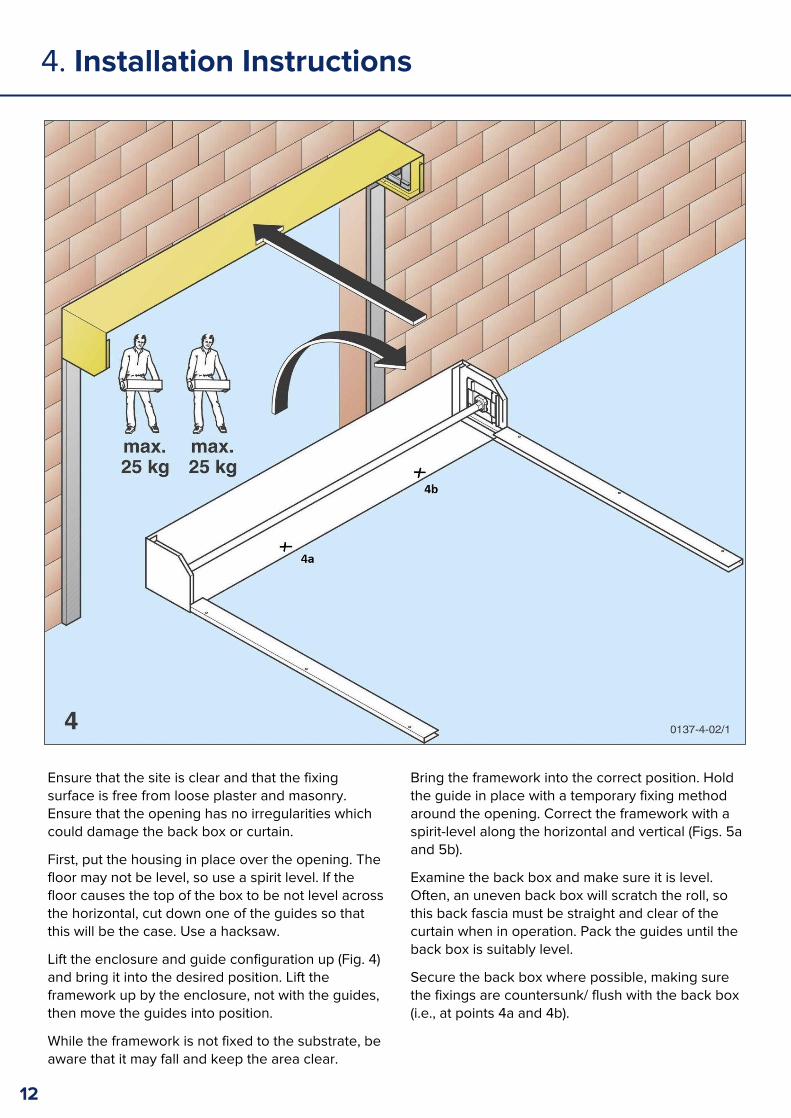
Ensure that the site is clear and that the fixing surface is free from loose plaster and masonry. Ensure that the opening has no irregularities which could damage the back box or curtain.
First, put the housing in place over the opening. The floor may not be level, so use a spirit level. If the floor causes the top of the box to be not level across the horizontal, cut down one of the guides so that this will be the case. Use a hacksaw.
Lift the enclosure and guide configuration up (Fig. 4) and bring it into the desired position. Lift the framework up by the enclosure, not with the guides, then move the guides into position.
While the framework is not fixed to the substrate, be aware that it may fall and keep the area clear.
Bring the framework into the correct position. Hold the guide in place with a temporary fixing method around the opening. Correct the framework with a spirit-level along the horizontal and vertical (Figs. 5a and 5b).
Examine the back box and make sure it is level. Often, an uneven back box will scratch the roll, so this back fascia must be straight and clear of the curtain when in operation. Pack the guides until the back box is suitably level.
Secure the back box where possible, making sure the fixings are countersunk/ flush with the back box (i.e., at points 4a and 4b).
12

4. Installation Instructions
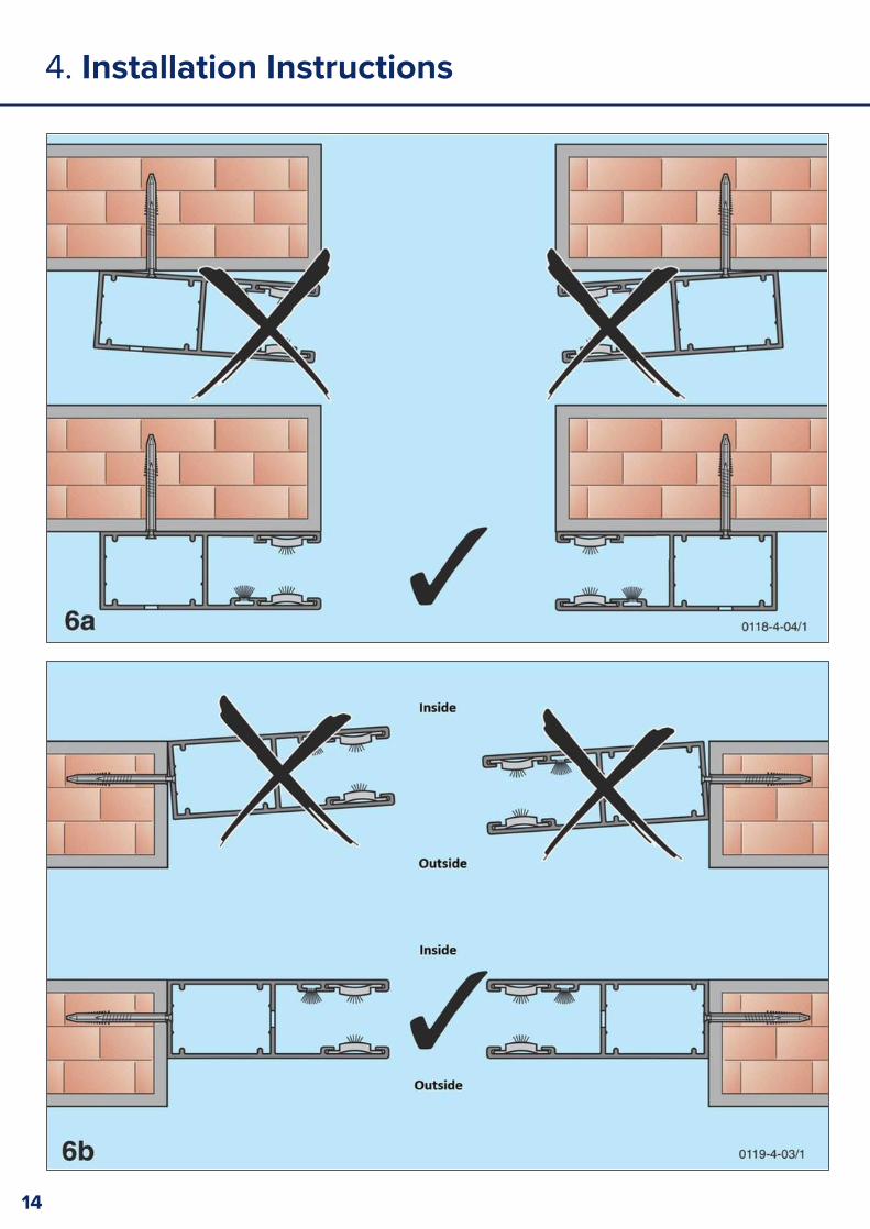
4.3.2. Fixing the Guide Channels
Note: It is essential that the guide channels are straight relative to each other. Packers may be required for masonry which does not offer a flush surface. Guides must always be level and fixed firmly (Fig 6a and 6b).
Fix both guides with the appropriate screws and apply the covering buttons (Fig 7a and 7b).
Ensure that the fixings used are suitable for the wall properties.
13
4. Installation Instructions
14
4. Installation Instructions
15
4. Installation Instructions
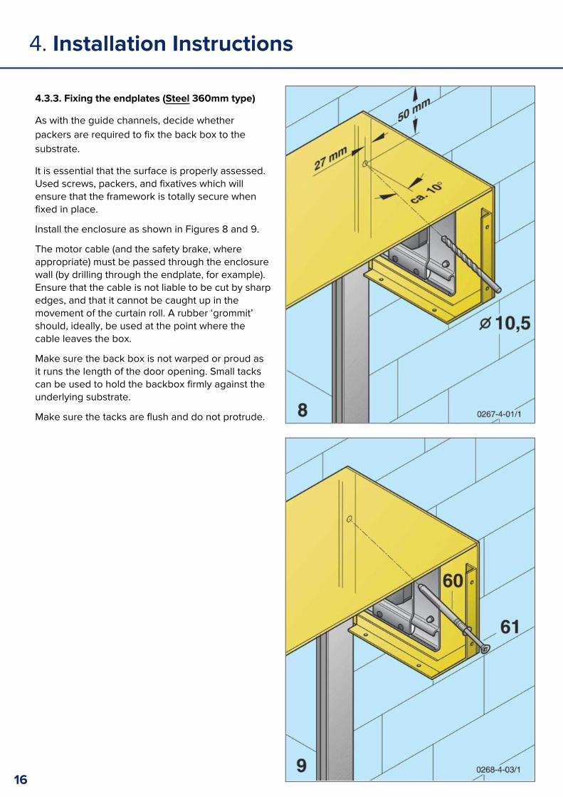
4.3.3. Fixing the endplates (Steel 360mm type)
As with the guide channels, decide whether packers are required to fix the back box to the substrate.
It is essential that the surface is properly assessed. Used screws, packers, and fixatives which will ensure that the framework is totally secure when fixed in place.
Install the enclosure as shown in Figures 8 and 9.
The motor cable (and the safety brake, where appropriate) must be passed through the enclosure wall (by drilling through the endplate, for example). Ensure that the cable is not liable to be cut by sharp edges, and that it cannot be caught up in the movement of the curtain roll. A rubber ‘grommit’ should, ideally, be used at the point where the cable leaves the box.
Make sure the back box is not warped or proud as it runs the length of the door opening. Small tacks can be used to hold the backbox firmly against the underlying substrate.
Make sure the tacks are flush and do not protrude.
16

4. Installation Instructions
4.3.4. Fixing the endplates (Aluminium 300mm type)
As with the guide channels, decide whether packers are required to fix the back box to the substrate.
It is essential that the surface is properly assessed. Use screws, packers, and fixatives which will ensure that the framework is totally secure when fixed in place.
Install the enclosure as shown in Figures 10 and 11.
The motor cable (and the safety brake, where appropriate) must be passed through the enclosure wall (by drilling through the endplate, for example). Ensure that the cable is not liable to be cut by sharp edges, and that it cannot be caught up in the movement of the curtain roll. A rubber ‘grommit’ should, ideally, be used at the point where the cable leaves the box.
Drill and screw the back of the box at regular points along the width of the door where possible. This is best done along the bottom edge or as close to bottom edge as possible. Make sure all screw heads are flush and not proud as this may damage the surface of the curtain later.
Note: It is important to ensure that the curtain is clear of the back box and fixings when running.
17
4. Installation Instructions
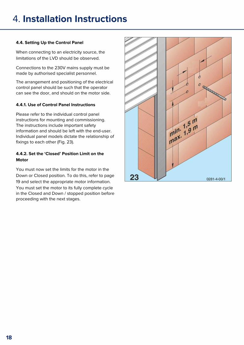
4.4. Setting Up the Control Panel
When connecting to an electricity source, the limitations of the LVD should be observed.
Connections to the 230V mains supply must be made by authorised specialist personnel.
The arrangement and positioning of the electrical control panel should be such that the operator can see the door, and should on the motor side.
4.4.1. Use of Control Panel Instructions
Please refer to the individual control panel instructions for mounting and commissioning. The instructions include important safety information and should be left with the end-user. Individual panel models dictate the relationship of fixings to each other (Fig. 23).
4.4.2. Set the ‘Closed’ Position Limit on the Motor
You must now set the limits for the motor in the Down or Closed position. To do this, refer to page 19 and select the appropriate motor information. You must set the motor to its fully complete cycle in the Closed and Down / stopped position before proceeding with the next stages.
18

4. Installation Instructions
4.4.3. Find the Down / Close Limit Setting: Somfy Motor (Press Button Type)
1. Remove the yellow limit cover if the white and yellow switches are not exposed.
2. For a left hand motor (see Fig. 24) the YELLOW limit switch governs the up / open stop position. The WHITE limit switch governs the down / closed stop position. For right hand motor, these are reversed.
3. Press the down / closed limit switch (it will stay semi-depressed). It will be the WHITE for a left hand motor.
4. Operate the motor by pressing the button on the control panel. Allow the motor to move in the closing direction (motor Fig 1) for two revolutions of the barrel, then stop the movement by pressing the control button on the control panel.
5. Press the down / close limit switch (it will fully release). The down limit is now set.
4.4.4. Find the Down / Close Limit Setting: Econom Screw Type Switch
Important: the limit switches which are used to set the limits must be those on the opposite side to the power cable!
1. For a left hand motor installation the switch in Motor Fig 2a is the down limit switch.
2. Press the control button on the control panel and allow the motor barrel to travel in the direction shown in Motor Fig 3. The motor will travel for between 2 and 20 full revolutions. Allow the motor to stop naturally.
3. The bottom / down limit is now set.
19
Barrel direction during closing
Barrel direction during closing
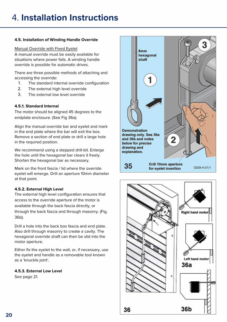
4.5. Installation of Winding Handle Override
Manual Override with Fixed EyeletA manual override must be easily available for situations where power fails. A winding handle override is possible for automatic drives.
There are three possible methods of attaching and accessing the override:1. The standard internal override configuration2. The external high level override3. The external low level override
4.5.1. Standard InternalThe motor should be aligned 45 degrees to the endplate enclosure. (See Fig 36a).
Align the manual override bar and eyelet and mark in the end plate where the bar will exit the box. Remove a section of end plate or drill a large hole in the required position.
We recommend using a stepped drill-bit. Enlarge the hole until the hexagonal bar clears it freely. Shorten the hexagonal bar as necessary.
Mark on the front fascia / lid where the override eyelet will emerge. Drill an aperture 10mm diameter at that point.
4.5.2. External High LevelThe external high level configuration ensures that access to the override aperture of the motor is available through the back fascia directly, or through the back fascia and through masonry. (Fig. 36b).
Drill a hole into the back box fascia and end plate. Also drill through masonry to create a cavity. The hexagonal override shaft can then be slid into the motor aperture.
Either fix the eyelet to the wall, or, if necessary, use the eyelet and handle as a removable tool known as a ‘knuckle joint’.
4.5.3. External Low Level See page 21.
4. Installation Instructions
20
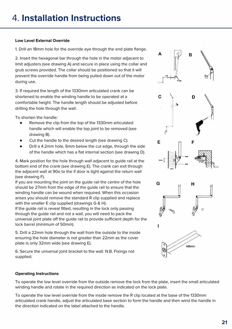
Low Level External Override
1. Drill an 18mm hole for the override eye through the end plate flange.
2. Insert the hexagonal bar through the hole in the motor adjacent to limit adjusters (see drawing A) and secure in place using the collar and grub screws provided. The collar should be positioned so that it will prevent the override handle from being pulled down out of the motor during use.
3. If required the length of the 1330mm articulated crank can be shortened to enable the winding handle to be operated at a comfortable height. The handle length should be adjusted before drilling the hole through the wall.
To shorten the handle:● Remove the clip from the top of the 1330mm articulated
handle which will enable the top joint to be removed (see drawing B).
● Cut the handle to the desired length (see drawing C).● Drill a 4.2mm hole, 6mm below the cut edge, through the side
of the handle which has a flat internal section (see drawing D).
4. Mark position for the hole through wall adjacent to guide rail at the bottom end of the crank (see drawing E). The crank can exit through the adjacent wall at 90o to the if door is tight against the return wall (see drawing F).If you are mounting the joint on the guide rail the centre of the hole should be 27mm from the edge of the guide rail to ensure that the winding handle can be wound when required. When this occasion arises you should remove the standard R clip supplied and replace with the smaller E clip supplied (drawings G & H). If the guide rail is reveal fitted, resulting in the lock only passing through the guide rail and not a wall, you will need to pack the universal joint plate off the guide rail to provide sufficient depth for the lock barrel (minimum of 50mm).
5. Drill a 22mm hole through the wall from the outside to the inside ensuring the hole diameter is not greater than 22mm as the cover plate is only 32mm wide (see drawing E).
6. Secure the universal joint bracket to the wall. N.B. Fixings not supplied.
4. Installation Instructions
Operating Instructions
To operate the low level override from the outside remove the lock from the plate, insert the small articulated winding handle and rotate in the required direction as indicated on the lock plate.
To operate the low level override from the inside remove the R clip located at the base of the 1330mm articulated crank handle, adjust the articulated base section to form the handle and then wind the handle in the direction indicated on the label attached to the handle.
21

4.6. Installation of the Curtain
Unwrap the curtain from its bubble wrap packing and lay the roll on a level surface – using the packing as a cushion. Resting it on a garden lawn is ideal.
Wrap the steel motor shaft in a temporary protective cover and hold it in place (e.g., use some of the wrapping from the curtain and hold it in place with some sticky tape).
Lift the roll of curtain, using at least two people, to the height of the enclosure and shaft. The maximum lifting weight for a person is 25kg and should not be exceeded. A lifting machine can be used where the curtain is especially heavy (Fig. 13).
4. Installation Instructions
Start to unravel the curtain, bottom and rubber rail first, over the shaft and down into the guide channels. Make sure the curtain is released into the guide channels under control. (See Fig. 14).
Autolocks or T-Springs (optional) must be fitted before the curtain is fully unravelled. Slide them onto the last slat of the curtain while the last slat hands over the shaft. The curtain can be held in place from below, (e.g., two blocks of timber at either end) while the autolocks / T-Springs adapter rail are slid onto the top slat.
22

4. Installation Instructions
23
4. Installation Instructions
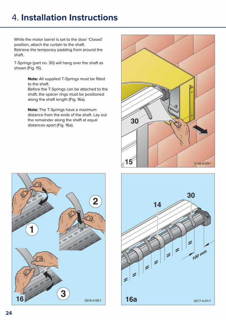
While the motor barrel is set to the door ‘Closed’ position, attach the curtain to the shaft. Retrieve the temporary padding from around the shaft.
T-Springs (part no. 30) will hang over the shaft as shown (Fig. 15).
Note: All supplied T-Springs must be fitted to the shaft. Before the T-Springs can be attached to the shaft, the spacer rings must be positioned along the shaft length (Fig. 16a).
Note: The T-Springs have a maximum distance from the ends of the shaft. Lay out the remainder along the shaft at equal distances apart (Fig. 16a).
24
4. Installation Instructions
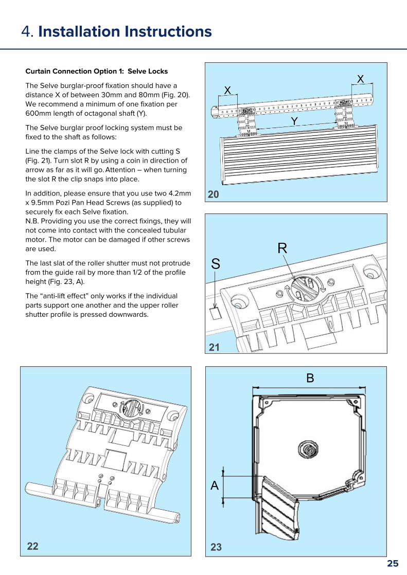
Curtain Connection Option 1: Selve Locks
The Selve burglar-proof fixation should have a distance X of between 30mm and 80mm (Fig. 20). We recommend a minimum of one fixation per 600mm length of octagonal shaft (Y).
The Selve burglar proof locking system must be fixed to the shaft as follows:
Line the clamps of the Selve lock with cutting S (Fig. 21). Turn slot R by using a coin in direction of arrow as far as it will go. Attention – when turning the slot R the clip snaps into place.
In addition, please ensure that you use two 4.2mm x 9.5mm Pozi Pan Head Screws (as supplied) to securely fix each Selve fixation. N.B. Providing you use the correct fixings, they will not come into contact with the concealed tubular motor. The motor can be damaged if other screws are used.
The last slat of the roller shutter must not protrude from the guide rail by more than 1/2 of the profile height (Fig. 23, A).
The “anti-lift effect” only works if the individual parts support one another and the upper roller shutter profile is pressed downwards.
20
21
22 23
B
A
25

4. Installation Instructions
Curtain Connection Option 2: Autolocks
Traditional autolocks are available as an alternative to the Selve system.
If the door is supplied with autolocks (item 31), these must be attached to the shaft as follows:
The outside autolocks should sit near to the guides. The remainder are then spread out equally along the shaft.
When the autolock rings are supplied with the shaft (32) of the 70 oct / 60 oct type, there are a pair of rings per autolock. These rings are fixed into place on the shaft with screws (Figs. 18 & 19).
Where adapter rail parts or lengths are supplied for the larger shafts (125mm), rivet the rail directly into the shaft.
4. Installation Instructions
26

4. Installation Instructions
4.7. Programming the motor
To set the limits on the motor, please consult the instructions of the individual motor manufacturer (see pages following, 4.7.1. & 4.7.2.).
Advice on top and bottom stop positions (limit setting):
The ideal door ‘closed’ point will be found when the slats are compressed down together and the curtain T-Springs bend inwards to force the top slat to rest lightly on the back box.
If autolocks are being used, the configuration should look as in Fig. 25.
27

4.7.1. Installation of Somfy motor (Push Button Type Limit Switches)
Note: Aluroll advise installers to ascertain whether the door is functioning mechanically before operating the door electrically. Before operating the motor with the remote control, open and close the door using the manual override handle. If the door moves up and down without obvious defects, proceed to set the limits.
Setting the ‘Door Closed’ Limit SwitchThis part of the commissioning of the door is complete (see page 19).
The two larger arrows point in the direction of rotation of the roller tube. If your tube is rotating in the same direction as arrow ‘A’ and the shutter is travelling downwards, the adjacent limit adjuster (A) would be the limit switch for the up / open motor travel direction. If the tube is rotating towards you and the shutter is travelling downwards, the adjacent limit adjuster (A) would be the down / close limit switch.
Rapid Limit Setting1. Run the motor in the down direction – without the curtain attached - until it stops at its internal limit. 2. Attach the curtain to the barrel. 3. Run the door in the up/open direction until the door stops short. Be ready to stop it with the key-fob / button if it
looks as if it will travel too far. 4. If the door has stopped short, turn the screw limit switch in the ‘+’ direction to allow the motor to travel further. If
the shutter travels too far upwards, turn the limit adjuster in the ‘-‘ direction, reverse the shutter, and send it upwards again. Turning the screw in the ‘-‘ direction will reduce the distance the motor will run.
Further Adjustment of the ‘Down’ Limit/ Door Closed Position1. Run the shutter in the down direction2. If the shutter stops before the fully closed position, turn the Down limit adjuster into the ‘+’ direction. 3. If the shutter travels past the bottom position, reduce the travel by turning the limit adjuster in the ‘-‘ direction.
Limit SwitchPress in the relevant up/open limit button. It will remain semi-depressed. (For a left hand motor installation, the Yellow limit button governs the up/open position. The white button governs the up/open position for a right hand installation.)To set the top limit, use the key-fob or the manual override winder to open the door and stop it when there are approximately two slats showing beneath the box. Turn the power off. Use the manual override to adjust the door so that one slat is showing (or, move the door up to the desire height. Never less than one full slat should be on display). Press the up limit switch (it will fully release). Turn the power back on and the top limit is now set. Replace the yellow plastic limit switch cover, prohibiting accidental pressing of the switch.
Note: The motor unit has an in-built thermal trip which will activate once the motor unit reaches a predetermined temperature. Repeat use of the fine-adjustment process of limit setting can cause the motor to cut out. Please wait approx. 15 minutes for the unit to return to normal operating mode when once the thermal trip has come into effect.
4.7.1. Installing the Econom/ Elero Motor (Screw-Type Limit Switches)
28
4. Installation Instructions

4. Installation Instructions
4.8. Override Lock (Optional)
An optional Lock for the override may be supplied. The lock will be fixed so as to cover any hole drilled for a removable override winder handle and hex bar.
Drill a hole into the lid or back box, where the removable override hex bar and handle will be inserted. Widen the hole so as to accommodate the key and lock. With the nut, fix the lock onto the lid / box.
To operate the manual override, remove the lock-barrel with the supplied key, insert the hexagonal override bar into the motor and turn to move the door up or down.
To lock and secure the override mechanism, remove the hexagonal bar and handle, then replace the barrel and key (Fig. 38).
Put the front lid inside the horizontal channel of the back box (1). Manoeuvre the lid into the whole channel across the length, and allow the lid to lie flat vertically down (2). Use screws or rivets (supplied) to fix the front lid in place (3).
29

4. Installation Instructions
4.9. Completing the Installation
All of the foregoing installation activities must go through a safety and operation assessment once the whole installation is complete. The installer can carry this out as follows:
Note:Before proceeding, thoroughly make sure that the moving parts such as the curtain and shaft, and the guides and enclosure, are clean of any debris or dirt.
Conduct a function check on the control panel according to the manufacturer’s instructions. Let the door open and close once, in order to examine all of the components installed for any change or unexpected function. At this point, double check the clearance between the curtain and the back box.
No hitches or interferences should occur. If unexpected or loud noises occur, or the door seems to jam, then stop the door movement immediately and check the level of the guides and the level of the shaft.
Operate the door by using the button on the wall-mounted control panel to send the door up and down three or four more times. (Note: the motor will heat up and the thermal trip will switch it off after 4 minutes of continuous operation. If this is the case, allow the motor to remain idle for 15 minutes).
A test of the safety features should be carried out through operation of the door via the control panel, then find out if the door stops when the bottom edge of the door meets an obstacle during a cycle (if the OSE beam is being used), or if the door stops when the PEC beam is broken by an object in its path.
30
Doors sizes 9m2 or less
The following method of dismantling requires two people, regardless of the size of the door.
1. Completely close the door and detach the curtain from the shaft by unscrewing the autolock rings / T-Springs.
2. Isolate the electrical supply and disconnect the motor from the control panel. Remove the control panel from the site.
3. Push the curtain up and over the shaft by hand so that it rolls over the shaft onto the other side. As it comes over the shaft, roll the curtain into a compact bundle. Once completely separate and in a roll, the curtain can be set aside, entire.
4. Unscrew the shaft fixings at the extreme left and right, then lower the shaft down and out of the way. 5. Unscrew fixings from the guides and box end caps.
5. Dismantling
Door sizes over 9m2
Always use two or more persons for this job; if possible, using lifting equipment, such as a forklift truck, as below.
1. Roll the door up completely by operating it in the ‘Open’ direction.2. Completely isolate the power supply at the fuse box / by unplugging.3. Dismantle the wiring so that electrical components such as the motor and safety brake are no longer
connected to other components. In the case of tubular motors, the safety brake will have to remain physically in place.
4. Use a forklift truck or hoist to support the rolled up door curtain from the endplates. Unscrew the bolts holding the shaft in place, then lift the shaft out of the endplates using the hoist / forklift.
5. Unscrew the guides and endplates; these can be removed.
31
6. Manufacturer’s Declaration
We, Aluroll Limited
Of Unit 6B, Mile Oak Industrial Estate, Maesbury Road, Oswestry, Shropshire, SY10 8GA
Declare that: Power Operated Roller Shutter Door
Models: T77, T55 Garage Door
Manufactured by: Aluroll Ltd.
Is in conformity with the essential Health and Safety requirements of the Machinery Directive 2006/42/EC. And conforms with the Low Voltage Directive 2006/95/EC, and the Electromagnetic Compatibility Directive 2004/108/EC.
A technical file of documentation has been compiled in accordance with Annex VII (Part 7 of Schedule 2), part B
Aluroll undertakes to transmit, in response to a reasoned request by the national authorities, relevant information on this partly completed machinery. Transmission shall be via electronic or paper copies, and shall be without prejudice to the intellectual property rights of the manufacturer of the partly completed machinery.
The product to which this Declaration of Incorporation relates must not be put into service until the relevant machinery into which it is to be incorporated has been declared in conformity with the provisions of the Machinery Directive.
Mark Evans J PowellGeneral Manager Quality & Design ManagerOswestry Oswestry
Declaration of Incorporation
32
7. Manufacturer’s Warranty
Aluroll Roller Doors – Classic, Compact & Elite
Warranties as stated below apply to all Aluroll roller garage doors. Please note, the warranty terms do not extend to cover labour and consequential loss arising from any claim. All Aluroll garage doors are guaranteed for a period of 5 years from the date of purchase. This covers parts and workmanship subject to correct installation, maintenance and operation. Wood laminate finishes carry an extended 10 year guarantee.
Product Warranty Conditions
1) Subject to the under mentioned specific limitations and exceptions, the manufacturer warrants all new doors, motors and electronic components of its manufacture to be free from defect in workmanship under normal use and service provided that notice of any claimed defect in material workmanship in or resulting from installation of any door has been given to the manufacturer within the period date of installation as prescribed in the schedule hereto.
2) This warranty does not apply to any defect, loss or arising or caused directly or indirectly by or as a result of:i) Any masonry rendered or other surfaces cracking or collapsing during installation of the door.ii) Any defect or deterioration of timber including drying out after installation.iii) Any weakening or collapse of the structure to which the doors are affixed occurring at any time after installation.iv) Any damage to or deterioration in the condition of the doors occurring in transit by customer nominated or appointed carrier or occurring after delivery and prior to installation.v) Any defect (including defects in component parts or accessories) rising from or attributable to the operation of the door after it is known to be defective.vi) Any door being installed within 1 mile of the sea or other body of water of equivalent or greater salt concentration or in an area subject to industrial fall out. vii) Any fault or surge in customer’s electricity supply.viii) The door striking an immovable object during travel. ix) Garage doors should be inspected upon delivery and viewed in natural light (not direct sunlight) from a standard distance of 3 metres to view their overall appearance. From this distance the door panel should appear free from marks or distortion, stains, blemishes, indentations or scuffs. Marks must be visible from a distance of 3 metres away to be considered under warranty. Aluroll strongly recommend installers use velcro to minimise rub marks on the concave (normally internal) face of the door.
3. Items excluded from warranty: i) Batteriesii) Fusesiii) Sensitivity adjustmentsiv) Minor factory repairsv) Light bulbs
4. While Aluroll doors are long lasting and hard wearing under normal conditions this warranty does not extend to inherent defects in steel or other materials used during manufacture. The manufacturer will however procure and assign to the customer the benefit of the warranty of the manufacturer of the steel or other material.
5. If Aluroll has at the request of the customer procured painting, powder coating or other surface application to its product this warranty does not extend to such surface application. For this purpose Aluroll acts as an agent for the customer at all times.
6. The manufacturer reserves the right to touch up on site the paint finish and/or pre-painted surfaces on its range of garage doors but no responsibility will be taken for the possibility of paint rubs, scuffing, etc., on the internal coat finish or external painted surface.
7. Proof of purchase must be provided to the manufacturer at time of warranty claim. If proof is not available any warranty may be invalid.
33
Conditions of Sale
1. Manufacture of Aluroll doors will not commence until accurate site measurements are available and can be checked.
2. Where Aluroll doors are made to suit floor levels, lintel heights or opening sizes guaranteed by the customer, any departure from the given sizes will be the responsibility of the customer as will any costs involved in alteration of made-up Aluroll doors.
3. Any delivery dates given are approximate only and the manufacturer accepts no liability for delay from any cause whatsoever. If by any reason or Act of God, war, government or semi-government enactment, regulation or restriction, lock-out, strike, industrial dispute, fire, tempest, flood, failure or inability to obtain licenses, transport or materials or any other cause beyond the manufacturer’s control, and delivery is delayed the manufacturer may extend the time of delivery or if the manufacturer is unable to deliver the contract shall be voidable at the manufacturer’s option with no right to either party for damage, loss, cost or expense.
4. If these conditions of sale (which shall be varied, modified or rescinded by written agreement executed by manufacturer) shall differ in any respect from the customer’s acceptance or confirmation then these conditions shall prevail.
5. Any claim for damaged product must be made within 2 days of delivery.
Aluroll recommends that all products be serviced by an authorised distributor every 12 months to ensure longevity of the product’s life.
7. Manufacturer’s Warranty
34

8. Service History
35
Date Test / Service ResultsSignature & Firm of
Engineer
Faults Corrected
Date Sign
9. Declaration of Conformity
36
Power Operated Roller Shutter Door
Model Type:
Serial Number:
Size (WxH):
Installed By:
The above power operated door (door, operator, safety devices, etc.), has been assembled, installed, connected and tested in accordance with the manufacturer’s instructions, at the following site address and is in conformity with the provisions of the Machinery Directive (89/392/EEC as amended by 91/368/EEC and 93/336/EEC), the Low Voltage Directive (73/23/EEC) and EMC Directive (89/336/EEC).
The Transposed Harmonised Standards used in the design of the above door are as follows: EN 13241-1:2003, & 12453:2001.
Site Address:
Declaration (made by Installation Engineer):
Signature:
Print name:
Date: Tel:
Declaration and instructions received by:
Signature:
Print name:
Date:
The Supply of Machinery (Safety) Regulations 1992EC Declaration of Conformity - Customer Copy

9. Declaration of Conformity
Power Operated Roller Shutter Door
Model Type:
Serial Number:
Size (WxH):
Installed By:
The above power operated door (door, operator, safety devices, etc.), has been assembled, installed, connected and tested in accordance with the manufacturer’s instructions, at the following site address and is in conformity with the provisions of the Machinery Directive (89/392/EEC as amended by 91/368/EEC and 93/336/EEC), the Low Voltage Directive (73/23/EEC) and EMC Directive (89/336/EEC).
The Transposed Harmonised Standards used in the design of the above door are as follows: EN 13241-1:2003, & 12453:2001.
Site Address:
Declaration (made by Installation Engineer):
Signature:
Print name:
Date: Tel:
Declaration and instructions received by:
Signature:
Print name:
Date:
The Supply of Machinery (Safety) Regulations 1992EC Declaration of Conformity - Installer Copy


NOTES

Unit 12, Artillery Business Park, Garrison Avenue,Park Hall, Oswestry, Shropshire SY11 4AD
Phone: 0800 977 8975 / 01691 679257 Fax: 01691 671482
www.aluroll.co.uk