Embed Size (px)
Citation preview
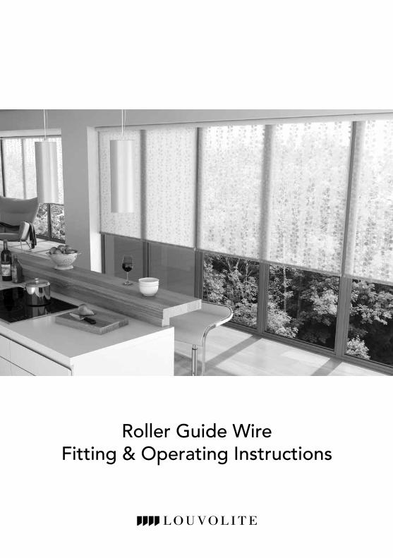
Roller Guide Wire Fitting & Operating Instructions
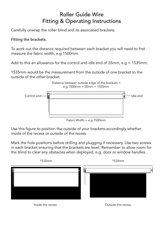
Carefully unwrap the roller blind and its associated brackets. Fitting the brackets.
To work out the distance required between each bracket you will need to first measure the fabric width, e.g 1500mm.
Add to this an allowance for the control and idle end of 35mm, e.g = 1535mm.
1535mm would be the measurement from the outside of one bracket to the outside of the other bracket.
Roller Guide Wire Fitting & Operating Instructions
Fabric Width = e.g 1500mm
Distance between outside edge of the brackets = e.g 1500mm + 35mm = 1535mm
Control end Idle end
Use this figure to position the outside of your brackets accordingly whether inside of the recess or outside of the recess
Mark the hole positions before drilling and plugging if necessary. Use two screws in each bracket ensuring that the brackets are level. Remember to allow room for the blind to clear any obstacles when deployed, e.g. door or window handles.
Inside the recess Outside the recess
1535mm1535mm
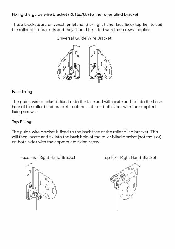
Fixing the guide wire bracket (R8166/88) to the roller blind bracket
These brackets are universal for left hand or right hand, face fix or top fix - to suit the roller blind brackets and they should be fitted with the screws supplied.
Universal Guide Wire Bracket
Top Fix - Right Hand BracketFace Fix - Right Hand Bracket
Face fixing
The guide wire bracket is fixed onto the face and will locate and fix into the base hole of the roller blind bracket - not the slot - on both sides with the supplied fixing screws.
Top Fixing
The guide wire bracket is fixed to the back face of the roller blind bracket. This will then locate and fix into the back hole of the roller blind bracket (not the slot) on both sides with the appropriate fixing screw.

System 45System 40System 32
From Extension Leg 10mm
In line with Extension Leg
From Extension Leg 5mm
An allowance is required for the bracket to be fixed away from the back of the recess. This is dependant on what system is to be used:
System 32 - Allow 10mm
System 40 - No allowance
System 45 - Allow 5mm
Fitting the Guide wire and blind
Attach a barrel clamp (R8190) to one end of an appropriate length of guide wire. Feed it from the top and down through the hole in the base of the guide wire brackets.

Place the roller blind into its brackets and deploy it to the bottom position.
Feed the wire through the end cap slot and down through the top cover. Attach a barrel clamp over the guide wire and pull taught to suit the drop. Tighten the barrel clamp and cut off the excess wire. Slide fit the top cover over the base plate.
Base Plate and Covers
Place and align the base plate and cover into the end caps and mark the correct position where it has to be fixed - this could be face or base fixed. Remove the top cover and then fasten the base plate with a No 6 screw.
Do this to both guide wires
Operate the blind up and down to check it operates correctly.

Your blind will be supplied with either Easybreak® connectors attached to the operating chain or a cord tidy that will need to be fitted to the wall.
Easybreak® System
Two Easybreak® connectors are connected to the operating chain 200mm apart. This ensures that at least one of them will be in the vertical position ensuring they perform as required.
If excessive weight is applied within the loop an Easybreak® connector will break apart.
If an Easybreak® connector comes apart then it will need to be re-connected. To re-connect, check the Easybreak® connector for damage. If undamaged, re-connect the chain by inserting the last ball on the end of the chain into the larger hole of the connector and push it into place.
Easybreak® Connector
Tensioned System using cord tidy. If the blind is fitted with a continuous loop chain then a cord tidy will be attached to the chain. This must be fitted to the wall as follows:
Fitting a side fix cord tidy.
The cord tidy is a two piece device and will arrive with a disposable red tab fitted to it.
200mm apart
Child Safety

Remove the disposable red tab by disengaging it from the chain and then pull out the disposable red tab.
Position the cord tidy to the wall at the furthest distance below the roller tube adding appropriate tension to the chain and mark its location.
Disposable retaining thrust washer
Disposable red tab
Disposable red tab
Cord tidy
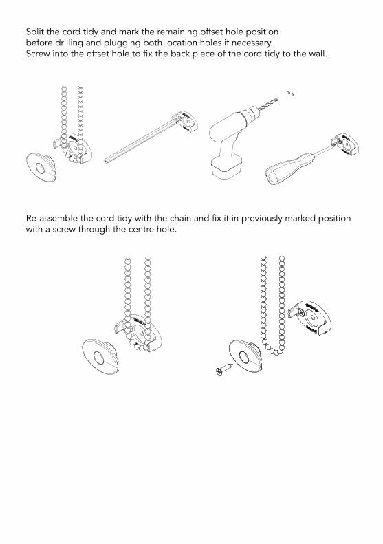
Split the cord tidy and mark the remaining offset hole position before drilling and plugging both location holes if necessary. Screw into the offset hole to fix the back piece of the cord tidy to the wall.
Re-assemble the cord tidy with the chain and fix it in previously marked position with a screw through the centre hole.
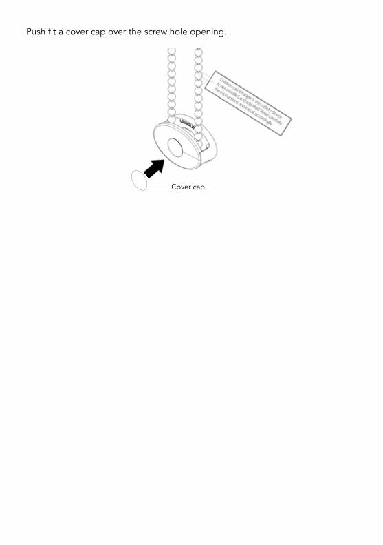
Push fit a cover cap over the screw hole opening.
Cover cap
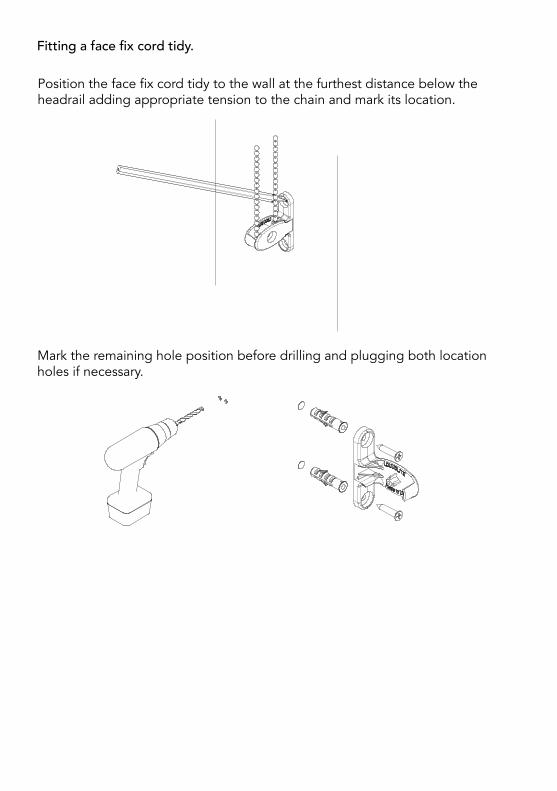
Fitting a face fix cord tidy.
Mark the remaining hole position before drilling and plugging both location holes if necessary.
Position the face fix cord tidy to the wall at the furthest distance below the headrail adding appropriate tension to the chain and mark its location.
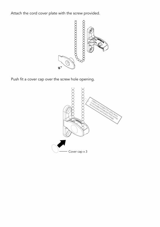
Push fit a cover cap over the screw hole opening.
Attach the cord cover plate with the screw provided.
Cover cap x 3

Operating the blind.
For a conventional roller blind, in order to lower the blind, pull the rearmost length of chain downwards with a smooth and steady pressure. To roll the blind up do the same on the front length of chain.
For a reverse roll blind the opposite is true, to lower use the front chain and to raise, use the rear chain.
NOTE TO INSTALLER: Please ensure a general child safety warning tag is fitted on the product.

Notes

Notes

Notes

S225
002
0234
4
WARNINGYoung children can be strangled by loops in pull cords, chains, tapes and inner cords that operate the product.
To avoid strangulation and entanglement, keep cords out of the reach of young children. Cords may become wrapped around a child’s neck. Move beds, cots and furniture away from window covering cords.
Do not tie cords together. Make sure cords do not twist and create a loop.
Breakaway Connector System
Floor
Blind drop size
Fixing height
max 2/3blind drop
Distance between chain & floor
Chain with 2 x Easybreak connectors spaced 200mm apart
2
3
1
Tensioned System with Cord Tidy
Blind drop size
Fixing height
Floor
Chain length
Distance between chain & floor
Cord tidy
2
3
1
If fixing height is unknown- Blind drop ≤ 2.5 metres, the
chain length must be ≤ 1 metre.
- Blind drop > 2.5 metres, the chain length must be drop of blind minus 1.5 metres.
If fixing height knownAll blind drop sizes, distance between floor and bottom of chain must be greater than 1.5 metres.
Cord tidyAffix a cord tidy to the wall at the maximum distance possible from the blind control mechanism ensuring all operating cords are taut (chain no more than 50mm apart at entry/exit of cord tidy).
If fixing height unknown- Blind drop ≤ 2.5 metres, the chain
length must be max 2/3 blind drop.
- Blind drop > 2.5 metres, the chain length must be max 2/3 blind drop.
If fixing height knownAll blind drop sizes, distance between floor and bottom of chain must be greater than 0.6 metres.
Chain must be fitted with 2 x Easybreak connectors 200mm apartWill break apart when excessive force is exerted on the chain.
Child Safety - BS EN 13120 Guidelines for Roller Blinds
NOTE TO INSTALLER: Please ensure general child safety warning tag is fitted on the product.
Roller Blind
Roller Blind
1
2
3
1
2
3
Also find us on:
Visit the Louvolite website to view the links to all of our assembly instructional videoswww.louvolite.com
Louvolite Customer Services Tel: 0161 882 5050 Email: [email protected]