Embed Size (px)
Citation preview
6-ROLLER PUMP
SERIES 1500
Max. Flow Rate: ................62 gpmMax. Pressure: ..................150 psi Max. RPM: ....................1000 rpmPorts: ....1-1/2" NPT Inlet & OutletShaft:................15/16" Dia. (Solid)Continuous Operation........100 psiIntermittent Operation........150 psi
5-ROLLER PUMP
Max. Flow Rate: ................45 gpmMax. Pressure: ................ 200 psi Max. RPM: ....................1000 rpmPorts:............1" NPT Inlet & Outlet............1-1/4" Hose Barb IncludedShaft:................15/16" Dia. (Solid)Continuous Operation........100 psiIntermittent Operation........200 psi
SERIES 1700
Max. Flow Rate: ............22.4 gpmMax.Pressure: ..................200 psi Max. RPM: ......................800 rpmPorts: ........3/4" NPT Inlet & Outlet..................1" Hose Barb IncludedShaft:................15/16" Dia. (Solid)Continuous Operation........100 psiIntermittent Operation........200 psi
7-ROLLER PUMP
SERIES 7700SERIES 75608-ROLLER PUMP
Max. Flow Rate: ................22 gpmMax. Pressure: ..................300 psi Max. RPM: ....................1000 rpmPorts: ........3/4" NPT Inlet & Outlet..................1" Hose Barb IncludedShaft:................15/16" Dia. (Solid)Continuous Operation........100 psiIntermittent Operation........300 psi
Max. Flow Rate: ................22 gpmMax. Pressure: ..................300 psiMax. RPM: ....................1200 rpmPorts: ........3/4" NPT Inlet & Outlet..................1" Hose Barb IncludedShaft:....................5/8" Dia. (Solid)Continuous Operation........100 psiIntermittent Operation........300 psi
Max. Flow Rate: ......9 gpm (4001)7 gpm (4101)
Max. Pressure: ..................150 psiMax. RPM:..........1800 rpm (4001)
2600 rpm (4101)Ports: ........3/4" NPT Inlet & OutletShaft:....................5/8" Dia. (Solid)
1/2" Dia. (Hollow)Continuous Operation........100 psiIntermittent Operation........150 psi
6-ROLLER PUMP
SERIES 6500SERIES 4001 & 41014-ROLLER PUMP
iron, Ni-Resist or the new SilverCast™ body, 416 stainlesssteel shaft, sealed factory-lubricated ball bearings,cartridge-type lip seals of Viton, Buna-N, and versatileSuper Rollers. (Super Rollers feature the life of nylon andthe chemical resistance of polypropylene.) Rotation for allmodels is counterclockwise for easy tractor PTO drive,except models 4001 and 4101 which are clockwise.Pumps are available in reverse rotation.
Hypro roller pumps are designed for agricultural andindustrial spraying and transfer of a variety fluids. Theseinclude insecticides, herbicides, emulsives, aromaticsolvents, liquid fertilizers and many other liquids. Theeconomical rotary-action roller principle requires no checkvalves while providing posit ive displacementcharacteristics with less friction and lower starting torquethan other pumps. Construction features include a cast-
ROLLER PUMPS
®®
¤¤
®®
OU
T
IN
OU
T
IN
®®
Installation, Operation, Repair and Parts Manual05/11, Rev. C
Description
Form L-0100R
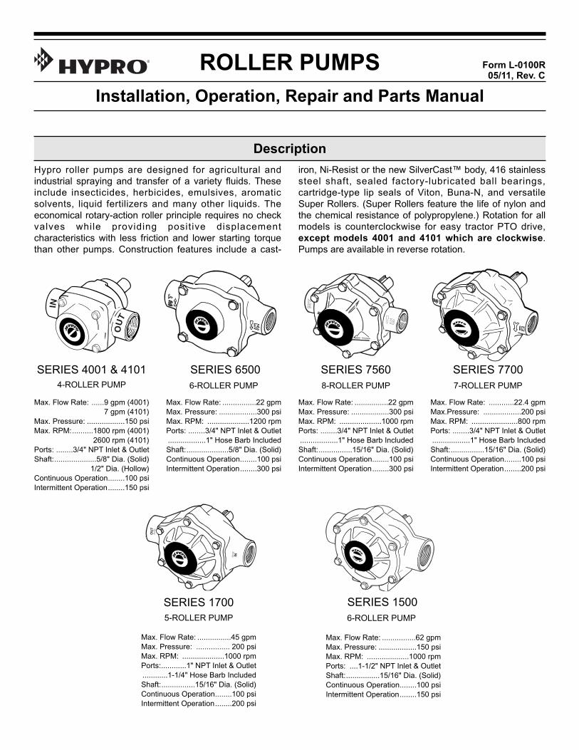
It is permissible to mount the torque arm with the chain inthe down position. To do this, mount the arm to the pump inthe reverse position. Do not use the tension spring or chain.
WARNING: Do not attach torque arm to movable linkages.
Figure A
7. Make certain that the power source conforms to therequirements of your equipment.
8. Provide adequate protection in guarding around themoving parts such as the shaft and pulleys.
9. Disconnect power before servicing.
10. Release all pressure within the system before servicingany component.
11. Drain all liquids from the system before servicing anycomponent.
12. Check all hoses for weak or worn condition before eachuse. Make certain that all connections are tight andsecure.
13. Periodically inspect the pump and the systemcomponents. Perform routine maintenance as required(see Maintenance section).
14. Never operate a gasoline engine in an enclosed area.Be sure the area is well ventilated.
15. Use only pipe, hose and fittings rated for the maximumpsi rating of the pump.
16. Never use these pumps for pumping water or otherliquids for human or animal consumption.
1. Use a pressure relief device on the discharge sideof the pump to prevent damage from pressurebuildup when the pump discharge is blocked orotherwise closed and the power source is stillrunning.
2. WARNING: Never pump flammable or explosivefluids such as gasoline, fuel oil, kerosene, etc.Never use in explosive atmospheres. The pumpshould be used only with liquids compatible withthe pump component materials. Failure to followthis warning can result in personal injury and/orproperty damage and will void the product warranty.
3. Never pump acids (i.e. acid fertilizer) with SuperRollers! When pumping acidic fertil izer, Hyprorecommends only the Silver Series castings and Teflonrollers, or use one of Hypro's poly centrifugal pumps.
4. Never run the pump faster than maximumrecommended speed.
5. Never pump at pressures higher than the maximumrecommended pressure.
6. Never pump liquids at temperatures higher than therecommended maximum temperatures (140°F/60°C).
engine for additional information. Read all safety informationbefore attempting to install or operate the pump.
This manual will cover the installation of the basic driveconfigurations available for Hypro roller pumps. Consult therecommendations of the manufacturer of your motor or
The preferred method for mounting the torque arm(3430-0540) and pump to a tractor is with the chains goingup to provide support for the pump (see Figure A). Attachthe torque arm to the pump with the long side of the arm onthe inlet side of the pump for this type of mounting. Manytractors do not have easy attachment points for securing thetension and torque chains. It may be necessary to drill holesin the tractor's master shield to attach the chains.
It is also acceptable to mount an angle iron on the mastershield to attach the chains. The chains should be attachedto the tractor as close to vertical as possible to avoid abending force on the pump.
1. Mount the pump and torque arm to the PTO shaftusing a Hypro series 1320, 1321 or 1323 coupler.
2. Attach the torque chain to the tractor frame with arm inhorizontal position.
3. Attach the tensioning chain to the tractor frame whileapplying tension to the spring.
2
General Safety Information
Drive Source Installation
Tractor PTO Installation
L-0100R (5/11, Rev. C)
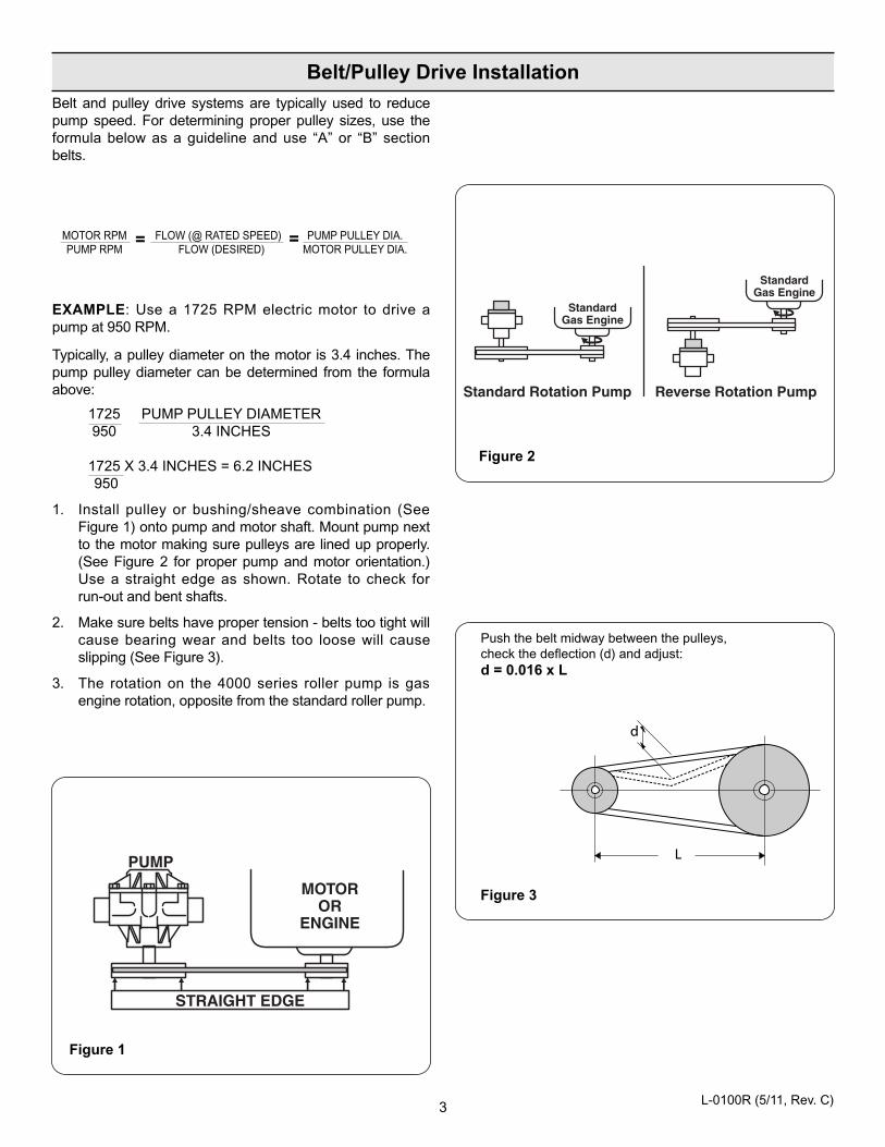
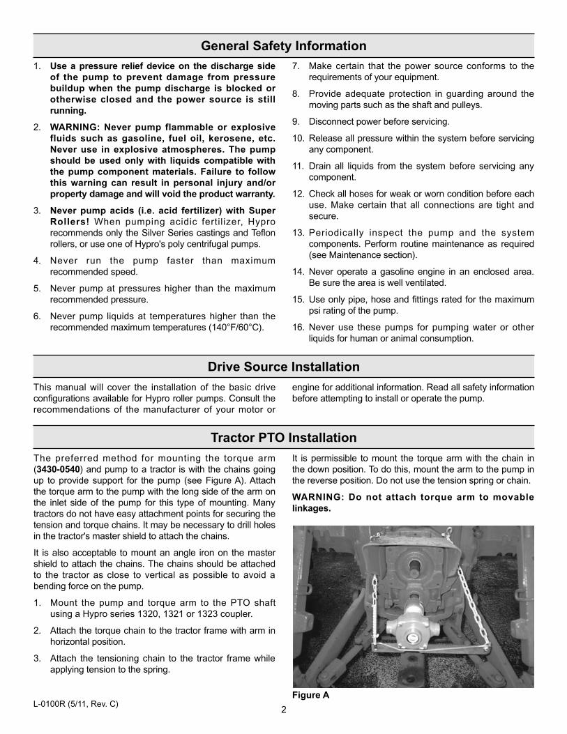
Figure 2
Figure 3
Figure 1
Push the belt midway between the pulleys, check the deflection (d) and adjust: d = 0.016 x L
==
Belt and pulley drive systems are typically used to reducepump speed. For determining proper pulley sizes, use theformula below as a guideline and use “A” or “B” sectionbelts.
MOTOR RPM FLOW (@ RATED SPEED) PUMP PULLEY DIA.PUMP RPM FLOW (DESIRED) MOTOR PULLEY DIA.
EXAMPLE: Use a 1725 RPM electric motor to drive a pump at 950 RPM.
Typically, a pulley diameter on the motor is 3.4 inches. Thepump pulley diameter can be determined from the formulaabove:
1725 PUMP PULLEY DIAMETER950 3.4 INCHES
1725 X 3.4 INCHES = 6.2 INCHES950
1. Install pulley or bushing/sheave combination (SeeFigure 1) onto pump and motor shaft. Mount pump nextto the motor making sure pulleys are lined up properly.(See Figure 2 for proper pump and motor orientation.)Use a straight edge as shown. Rotate to check for run-out and bent shafts.
2. Make sure belts have proper tension - belts too tight willcause bearing wear and belts too loose will causeslipping (See Figure 3).
3. The rotation on the 4000 series roller pump is gasengine rotation, opposite from the standard roller pump.
3
d
L
Belt/Pulley Drive Installation
L-0100R (5/11, Rev. C)
6. A strainer should be installed in the suction line. Cleanthe strainer as soon as it becomes clogged.
7. Never attach an agitator or any restriction to abypass line of a pressure relief device becausesystem damage may occur.
Figure 4
NOTE: Use only pipe, fittings, accessories, hose, etc.rated for the maximum pressure rating of the pump.
1. Select adequate size drive unit to avoid overloading.Avoid unnecessary restrictions in the line such aselbows, check valves, and all extraneous curves andbends.
2. Avoid using looped sections of tubing or pipe whichmight permit air to become trapped.
3. Use pipe joint sealant on pipe threads to assurewatertight connections.
4. Selection of the right type and size of hose is vital togood performance. Be sure to hook up the lines to theproper ports on the pump.
5. Always use a good quality suction hose (one or twobraid reinforced hose to prevent collapse) of atleast the same diameter as the inlet port of thepump. If the suction (inlet) hose is more than fourfeet long, then use the next larger size.
air. Make sure line strainer is free of debris. If pump doesnot self-prime, disconnect suction hose, fill with water andreconnect to liquid source. Often a squirt of oil into the portsof the pump will seal clearances and help priming.
Care of the Pump
Hypro roller pumps are all carefully machined to closetolerance - high pressure operation depends on close-fittingparts. Proper care and maintenance will keep your pumpwear at a minimum and will keep it running smoothly andtrouble-free for a long time.
WARNING: Never pump corrosive or abrasive liquids asthese will cause rapid wear or deterioration of body, rotor,shaft and seals in the pump. The pump should be used onlywith liquids compatible with pump component materials.Never exceed maximum specified rpm and pressure. Neverrun pump dry. Failure to follow this warning will void theproduct warranty.
Priming the Pump
To help prime the pump, keep the inlet or suction line asshort as possible with a minimum of bends, elbows andkinks. Make sure all connections are tight and do not leak
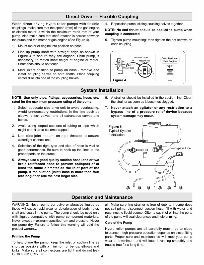
When direct driving Hypro roller pumps with flexiblecouplings, make sure that the speed (rpm) of the gas engineor electric motor is within the maximum rated rpm of yourpump. Also make sure that shaft rotation is correct betweenthe pump and the motor or gas engine (See Figure 4).
1. Mount motor or engine into position on base.
2. Line up pump shaft with straight edge as shown inFigure 4 to assure they are aligned. Shim pump, ifnecessary, to match shaft height of engine or motor.Shaft ends should not touch.
3. Mark exact position of pump on base - remove andinstall coupling halves on both shafts. Place couplingcenter disc into one of the coupling halves.
4. Reposition pump, sliding coupling halves together.
NOTE: No end thrust should be applied to pump whencoupling is connected.
5. Tighten pump mounting; then tighten the set screws oneach coupling.
4
Direct Drive — Flexible Coupling
System Installation
Operation and Maintenance
Figure 5Typical System Installation
Bypass Line
L-0100R (5/11, Rev. C)
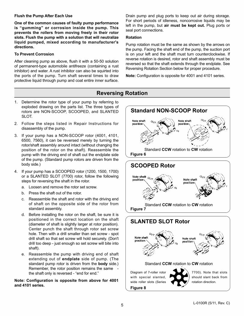
Figure 8
Figure 7
Figure 6
Standard CCW rotation to CW rotation
Standard CCW rotation to CW rotation
Standard CCW rotation to CW rotation
7700). Note that slots
should slant back from
rotation direction.
Diagram of 7-roller rotor
with special slanted,
wide roller slots (Series
SLANTED SLOT Rotor
SCOOPED Rotor
Standard NON-SCOOP Rotor
1. Determine the rotor type of your pump by referring toexploded drawing on the parts list. The three types ofrotors are NON-SCOOP, SCOOPED, and SLANTEDSLOT.
2. Follow the steps listed in Repair Instructions fordisassembly of the pump.
3. If your pump has a NON-SCOOP rotor (4001, 4101,6500, 7560), it can be reversed merely by turning therotor/shaft assembly around intact (without changing theposition of the rotor on the shaft). Reassemble thepump with the driving end of shaft out the endplate sideof the pump. (Standard pump rotors are driven from thebody side.)
4. If your pump has a SCOOPED rotor (1200, 1500, 1700)or a SLANTED SLOT (7700) rotor, follow the followingsteps for reversing the shaft in the rotor.
a. Loosen and remove the rotor set screw.
b. Press the shaft out of the rotor.
c. Reassemble the shaft and rotor with the driving endof shaft on the opposite side of the rotor fromstandard assembly.
d. Before installing the rotor on the shaft, be sure it ispositioned in the correct location on the shaft(diameter of shaft is slightly larger at rotor position).Center punch the shaft through rotor set screwhole. Then with a drill smaller than set screw - spotdrill shaft so that set screw will hold securely. (Don'tdrill too deep - just enough so set screw will bite intoshaft).
e. Reassemble the pump with driving end of shaftextending out of endplate side of pump. (Thestandard pump rotor is driven from the body side.)Remember, the rotor position remains the same -the shaft only is reversed - “end for end.”
Note: Configuration is opposite from above for 4001and 4101 series.
Flush the Pump After Each Use
One of the common causes of faulty pump performanceis “gumming” or corrosion inside the pump. This prevents the rollers from moving freely in their rotorslots. Flush the pump with a solution that will neutralizeliquid pumped, mixed according to manufacturer's directions.
To Prevent Corrosion
After cleaning pump as above, flush it with a 50-50 solutionof permanent-type automobile antifreeze (containing a rustinhibitor) and water. A rust inhibitor can also be squirted intothe ports of the pump. Turn shaft several times to drawprotective liquid through pump and coat entire inner surface.
Drain pump and plug ports to keep out air during storage.For short periods of idleness, noncorrosive liquids may beleft in the pump, but air must be kept out. Plug ports orseal port connections.
Rotation
Pump rotation must be the same as shown by the arrows onthe pump. Facing the shaft end of the pump, the suction portis on your left and the shaft must turn counterclockwise. Ifreverse rotation is desired, rotor and shaft assembly must bereversed so that the shaft extends through the endplate. SeeReversing Rotation Section below for proper procedure.
Note: Configuration is opposite for 4001 and 4101 series.
5
Reversing Rotation
L-0100R (5/11, Rev. C)
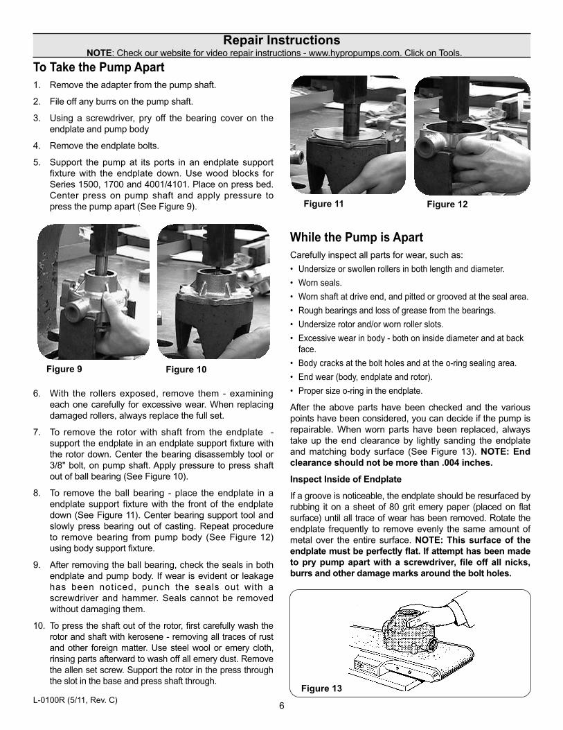
Figure 13
Figure 12Figure 11
Figure 10Figure 9
6. With the rollers exposed, remove them - examiningeach one carefully for excessive wear. When replacingdamaged rollers, always replace the full set.
7. To remove the rotor with shaft from the endplate -support the endplate in an endplate support fixture withthe rotor down. Center the bearing disassembly tool or3/8" bolt, on pump shaft. Apply pressure to press shaftout of ball bearing (See Figure 10).
8. To remove the ball bearing - place the endplate in aendplate support fixture with the front of the endplatedown (See Figure 11). Center bearing support tool andslowly press bearing out of casting. Repeat procedureto remove bearing from pump body (See Figure 12)using body support fixture.
9. After removing the ball bearing, check the seals in bothendplate and pump body. If wear is evident or leakagehas been noticed, punch the seals out with ascrewdriver and hammer. Seals cannot be removedwithout damaging them.
10. To press the shaft out of the rotor, first carefully wash therotor and shaft with kerosene - removing all traces of rustand other foreign matter. Use steel wool or emery cloth,rinsing parts afterward to wash off all emery dust. Removethe allen set screw. Support the rotor in the press throughthe slot in the base and press shaft through.
To Take the Pump Apart1. Remove the adapter from the pump shaft.
2. File off any burrs on the pump shaft.
3. Using a screwdriver, pry off the bearing cover on theendplate and pump body
4. Remove the endplate bolts.
5. Support the pump at its ports in an endplate supportfixture with the endplate down. Use wood blocks forSeries 1500, 1700 and 4001/4101. Place on press bed.Center press on pump shaft and apply pressure topress the pump apart (See Figure 9).
While the Pump is ApartCarefully inspect all parts for wear, such as:
• Undersize or swollen rollers in both length and diameter.
• Worn seals.
• Worn shaft at drive end, and pitted or grooved at the seal area.
• Rough bearings and loss of grease from the bearings.
• Undersize rotor and/or worn roller slots.
• Excessive wear in body - both on inside diameter and at backface.
• Body cracks at the bolt holes and at the o-ring sealing area.
• End wear (body, endplate and rotor).
• Proper size o-ring in the endplate.
After the above parts have been checked and the variouspoints have been considered, you can decide if the pump isrepairable. When worn parts have been replaced, alwaystake up the end clearance by lightly sanding the endplateand matching body surface (See Figure 13). NOTE: Endclearance should not be more than .004 inches.
Inspect Inside of Endplate
If a groove is noticeable, the endplate should be resurfaced byrubbing it on a sheet of 80 grit emery paper (placed on flatsurface) until all trace of wear has been removed. Rotate theendplate frequently to remove evenly the same amount ofmetal over the entire surface. NOTE: This surface of theendplate must be perfectly flat. If attempt has been madeto pry pump apart with a screwdriver, file off all nicks,burrs and other damage marks around the bolt holes.
6
Repair InstructionsNOTE: Check our website for video repair instructions - www.hypropumps.com. Click on Tools.
L-0100R (5/11, Rev. C)
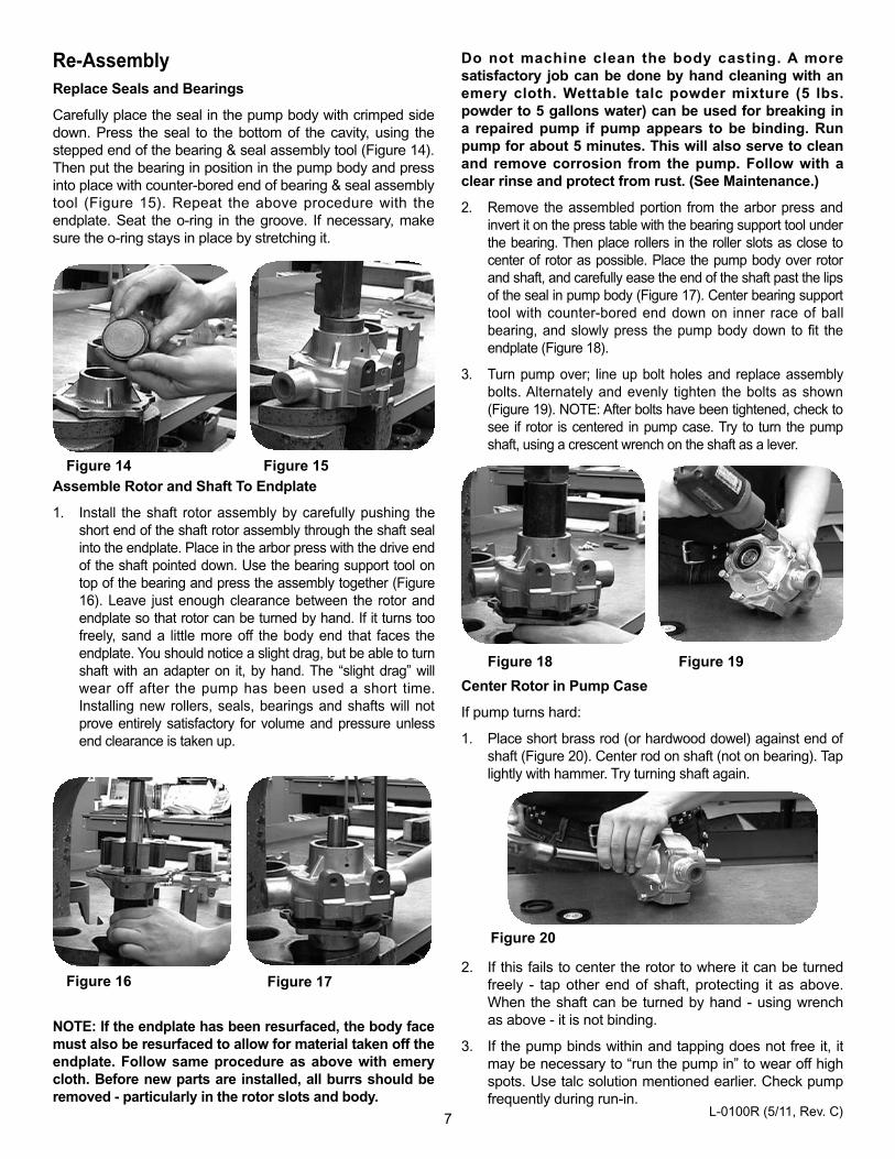
Figure 20
Figure 19Figure 18
Figure 17Figure 16
Figure 15Figure 14
NOTE: If the endplate has been resurfaced, the body facemust also be resurfaced to allow for material taken off theendplate. Follow same procedure as above with emerycloth. Before new parts are installed, all burrs should beremoved - particularly in the rotor slots and body.
Do not machine clean the body casting. A moresatisfactory job can be done by hand cleaning with anemery cloth. Wettable talc powder mixture (5 lbs.powder to 5 gallons water) can be used for breaking ina repaired pump if pump appears to be binding. Runpump for about 5 minutes. This will also serve to cleanand remove corrosion from the pump. Follow with aclear rinse and protect from rust. (See Maintenance.)
2. Remove the assembled portion from the arbor press andinvert it on the press table with the bearing support tool underthe bearing. Then place rollers in the roller slots as close tocenter of rotor as possible. Place the pump body over rotorand shaft, and carefully ease the end of the shaft past the lipsof the seal in pump body (Figure 17). Center bearing supporttool with counter-bored end down on inner race of ballbearing, and slowly press the pump body down to fit theendplate (Figure 18).
3. Turn pump over; line up bolt holes and replace assemblybolts. Alternately and evenly tighten the bolts as shown(Figure 19). NOTE: After bolts have been tightened, check tosee if rotor is centered in pump case. Try to turn the pumpshaft, using a crescent wrench on the shaft as a lever.
2. If this fails to center the rotor to where it can be turnedfreely - tap other end of shaft, protecting it as above.When the shaft can be turned by hand - using wrenchas above - it is not binding.
3. If the pump binds within and tapping does not free it, itmay be necessary to “run the pump in” to wear off highspots. Use talc solution mentioned earlier. Check pumpfrequently during run-in.
Assemble Rotor and Shaft To Endplate
1. Install the shaft rotor assembly by carefully pushing theshort end of the shaft rotor assembly through the shaft sealinto the endplate. Place in the arbor press with the drive endof the shaft pointed down. Use the bearing support tool ontop of the bearing and press the assembly together (Figure16). Leave just enough clearance between the rotor andendplate so that rotor can be turned by hand. If it turns toofreely, sand a little more off the body end that faces theendplate. You should notice a slight drag, but be able to turnshaft with an adapter on it, by hand. The “slight drag” willwear off after the pump has been used a short time.Installing new rollers, seals, bearings and shafts will notprove entirely satisfactory for volume and pressure unlessend clearance is taken up.
Re-AssemblyReplace Seals and Bearings
Carefully place the seal in the pump body with crimped sidedown. Press the seal to the bottom of the cavity, using thestepped end of the bearing & seal assembly tool (Figure 14).Then put the bearing in position in the pump body and pressinto place with counter-bored end of bearing & seal assemblytool (Figure 15). Repeat the above procedure with theendplate. Seat the o-ring in the groove. If necessary, makesure the o-ring stays in place by stretching it.
Center Rotor in Pump Case
If pump turns hard:
1. Place short brass rod (or hardwood dowel) against end ofshaft (Figure 20). Center rod on shaft (not on bearing). Taplightly with hammer. Try turning shaft again.
7 L-0100R (5/11, Rev. C)
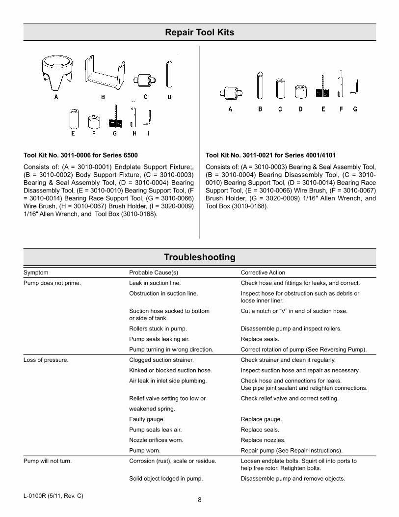
Tool Kit No. 3011-0021 for Series 4001/4101
Consists of: (A = 3010-0003) Bearing & Seal Assembly Tool, (B = 3010-0004) Bearing Disassembly Tool, (C = 3010-0010) Bearing Support Tool, (D = 3010-0014) Bearing RaceSupport Tool, (E = 3010-0066) Wire Brush, (F = 3010-0067)Brush Holder, (G = 3020-0009) 1/16" Allen Wrench, andTool Box (3010-0168).
Tool Kit No. 3011-0006 for Series 6500
Consists of: (A = 3010-0001) Endplate Support Fixture;,(B = 3010-0002) Body Support Fixture, (C = 3010-0003)Bearing & Seal Assembly Tool, (D = 3010-0004) BearingDisassembly Tool, (E = 3010-0010) Bearing Support Tool, (F= 3010-0014) Bearing Race Support Tool, (G = 3010-0066)Wire Brush, (H = 3010-0067) Brush Holder, (I = 3020-0009)1/16" Allen Wrench, and Tool Box (3010-0168).
Symptom Probable Cause(s) Corrective Action
Pump does not prime. Leak in suction line. Check hose and fittings for leaks, and correct.
Obstruction in suction line. Inspect hose for obstruction such as debris or loose inner liner.
Suction hose sucked to bottom Cut a notch or “V” in end of suction hose.or side of tank.
Rollers stuck in pump. Disassemble pump and inspect rollers.
Pump seals leaking air. Replace seals.
Pump turning in wrong direction. Correct rotation of pump (See Reversing Pump).
Loss of pressure. Clogged suction strainer. Check strainer and clean it regularly.
Kinked or blocked suction hose. Inspect suction hose and repair as necessary.
Air leak in inlet side plumbing. Check hose and connections for leaks.Use pipe joint sealant and retighten connections.
Relief valve setting too low or Check relief valve and correct setting.
weakened spring.
Faulty gauge. Replace gauge.
Pump seals leak air. Replace seals.
Nozzle orifices worn. Replace nozzles.
Pump worn. Repair pump (See Repair Instructions).
Pump will not turn. Corrosion (rust), scale or residue. Loosen endplate bolts. Squirt oil into ports tohelp free rotor. Retighten bolts.
Solid object lodged in pump. Disassemble pump and remove objects.
8
Repair Tool Kits
Troubleshooting
L-0100R (5/11, Rev. C)
HYPR
O
2222C
555555555
IMPORTANT:
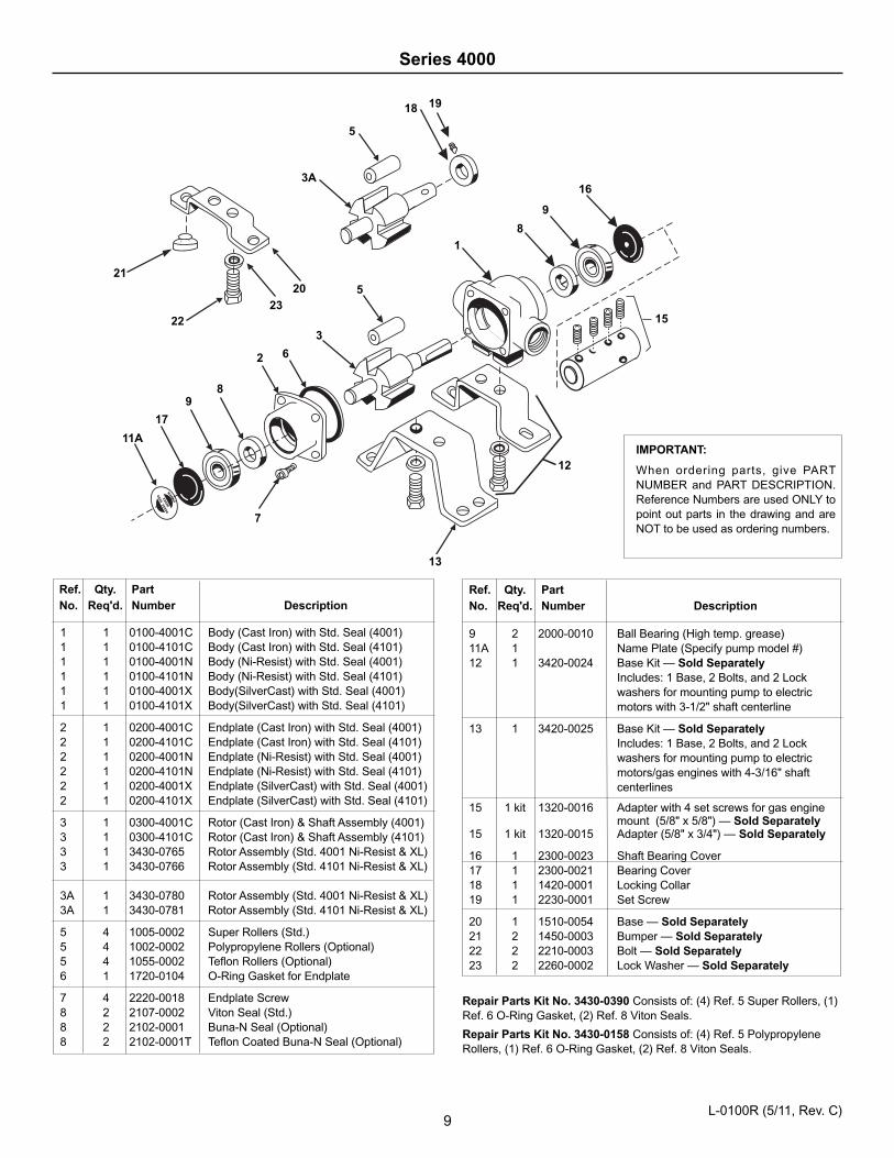
When ordering parts, give PARTNUMBER and PART DESCRIPTION.Reference Numbers are used ONLY topoint out parts in the drawing and areNOT to be used as ordering numbers.
Ref. Qty. PartNo. Req'd. Number Description
1 1 0100-4001C Body (Cast Iron) with Std. Seal (4001)1 1 0100-4101C Body (Cast Iron) with Std. Seal (4101)1 1 0100-4001N Body (Ni-Resist) with Std. Seal (4001)1 1 0100-4101N Body (Ni-Resist) with Std. Seal (4101)1 1 0100-4001X Body(SilverCast) with Std. Seal (4001)1 1 0100-4101X Body(SilverCast) with Std. Seal (4101)
2 1 0200-4001C Endplate (Cast Iron) with Std. Seal (4001)2 1 0200-4101C Endplate (Cast Iron) with Std. Seal (4101)2 1 0200-4001N Endplate (Ni-Resist) with Std. Seal (4001)2 1 0200-4101N Endplate (Ni-Resist) with Std. Seal (4101)2 1 0200-4001X Endplate (SilverCast) with Std. Seal (4001)2 1 0200-4101X Endplate (SilverCast) with Std. Seal (4101)
3 1 0300-4001C Rotor (Cast Iron) & Shaft Assembly (4001)3 1 0300-4101C Rotor (Cast Iron) & Shaft Assembly (4101)3 1 3430-0765 Rotor Assembly (Std. 4001 Ni-Resist & XL)3 1 3430-0766 Rotor Assembly (Std. 4101 Ni-Resist & XL)
3A 1 3430-0780 Rotor Assembly (Std. 4001 Ni-Resist & XL)3A 1 3430-0781 Rotor Assembly (Std. 4101 Ni-Resist & XL)
5 4 1005-0002 Super Rollers (Std.)5 4 1002-0002 Polypropylene Rollers (Optional)5 4 1055-0002 Teflon Rollers (Optional)6 1 1720-0104 O-Ring Gasket for Endplate
7 4 2220-0018 Endplate Screw8 2 2107-0002 Viton Seal (Std.)8 2 2102-0001 Buna-N Seal (Optional)8 2 2102-0001T Teflon Coated Buna-N Seal (Optional)
9
Series 4000
Repair Parts Kit No. 3430-0390 Consists of: (4) Ref. 5 Super Rollers, (1)Ref. 6 O-Ring Gasket, (2) Ref. 8 Viton Seals.
Repair Parts Kit No. 3430-0158 Consists of: (4) Ref. 5 PolypropyleneRollers, (1) Ref. 6 O-Ring Gasket, (2) Ref. 8 Viton Seals.
Ref. Qty. PartNo. Req'd. Number Description
9 2 2000-0010 Ball Bearing (High temp. grease)11A 1 Name Plate (Specify pump model #)12 1 3420-0024 Base Kit — Sold Separately
Includes: 1 Base, 2 Bolts, and 2 Lock washers for mounting pump to electric motors with 3-1/2" shaft centerline
13 1 3420-0025 Base Kit — Sold Separately Includes: 1 Base, 2 Bolts, and 2 Lock washers for mounting pump to electric motors/gas engines with 4-3/16" shaft centerlines
15 1 kit 1320-0016 Adapter with 4 set screws for gas engine mount (5/8" x 5/8") — Sold Separately
15 1 kit 1320-0015 Adapter (5/8" x 3/4") — Sold Separately
16 1 2300-0023 Shaft Bearing Cover17 1 2300-0021 Bearing Cover18 1 1420-0001 Locking Collar19 1 2230-0001 Set Screw
20 1 1510-0054 Base — Sold Separately21 2 1450-0003 Bumper — Sold Separately22 2 2210-0003 Bolt — Sold Separately23 2 2260-0002 Lock Washer — Sold Separately
3A
23
21
22
20
5
18 19
1
5
3
2
7
89
17
11A
6
8
9
16
13
15
12
L-0100R (5/11, Rev. C)
10
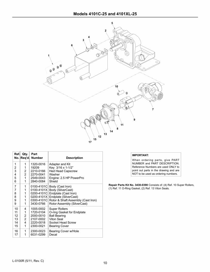
IMPORTANT:
When ordering parts, give PARTNUMBER and PART DESCRIPTION.Reference Numbers are used ONLY topoint out parts in the drawing and areNOT to be used as ordering numbers.
Ref. Qty. PartNo. Req'd. Number Description
1 1 1320-0016 Adapter and Kit2 1 19209 Key 3/16 x 1-1/2”3 2 2210-0166 Hed Head Capscrew4 2 2270-0041 Washer5 1 2549-0043 Engine: 2.5 HP PowerPro6 1 2840-0084 Shield
7 1 0100-4101C Body (Cast Iron)7 1 0100-4101X Body (SilverCast)8 1 0200-4101C Endplate (Cast Iron)8 1 0200-4101X Endplate (SilverCast)9 1 0300-4101C Rotor & Shaft Assembly (Cast Iron)9 1 3430-0766 Rotor Assembly (SilverCast)
10 4 1005-0002 Super Rollers11 1 1720-0104 O-ring Gasket for Endplate12 2 2000-0010 Ball Bearing13 2 2107-0002 Viton Seal14 4 2220-0018 Socket Head Screw15 1 2300-0021 Bearing Cover
16 1 2300-0023 Bearing Cover w/Hole17 1 6031-0299 Decal
Models 4101C-25 and 4101XL-25
6
1
1715
1213
148
11
9
7
10
34
2
5
L-0100R (5/11, Rev. C)
Repair Parts Kit No. 3430-0390 Consists of: (4) Ref. 10 Super Rollers,(1) Ref. 11 O-Ring Gasket, (2) Ref. 13 Viton Seals.
11
Series 6500
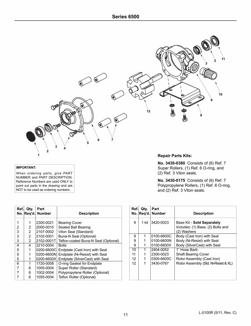
Repair Parts Kits:
No. 3430-0380 Consists of (6) Ref. 7Super Rollers, (1) Ref. 6 O-ring, and(2) Ref. 3 Viton seals.
No. 3430-0175 Consists of (6) Ref. 7Polypropylene Rollers, (1) Ref. 6 O-ring,and (2) Ref. 3 Viton seals.
Ref. Qty. PartNo. Req'd. Number Description
1 1 2300-0021 Bearing Cover2 2 2000-0010 Sealed Ball Bearing3 2 2107-0002 Viton Seal (Standard)3 2 2102-0001 Buna-N Seal (Optional)3 2 2102-0001T Teflon-coated Buna-N Seal (Optional)4 4 2210-0004 Bolts5 1 0200-6600C Endplate (Cast Iron) with Seal5 1 0200-6600N Endplate (Ni-Resist) with Seal5 1 0200-6600X Endplate (SilverCast) with Seal6 1 1720-0008 O-ring Gasket for Endplate7 6 1005-0004 Super Roller (Standard)7 6 1002-0004 Polypropylene Roller (Optional)7 6 1055-0004 Teflon Roller (Optional)
Ref. Qty. PartNo. Req'd. Number Description
8 1 kit 3420-0023 Base Kit - Sold SeparatelyIncludes: (1) Base, (2) Bolts and(2) Washers
9 1 0100-6600C Body (Cast Iron) with Seal9 1 0100-6600N Body (Ni-Resist) with Seal9 1 0100-6600X Body (SilverCast) with Seal
10 1 2404-0052 1” Hose Barb11 1 2300-0023 Shaft Bearing Cover12 1 0300-6600C Rotor Assembly (Cast Iron)12 1 3430-0767 Rotor Assembly (Std. Ni-Resist & XL)
56 7
128
9
10
23
11
12
3 4
IMPORTANT:
When ordering parts, give PARTNUMBER and PART DESCRIPTION.Reference Numbers are used ONLY topoint out parts in the drawing and areNOT to be used as ordering numbers.
L-0100R (5/11, Rev. C)
12
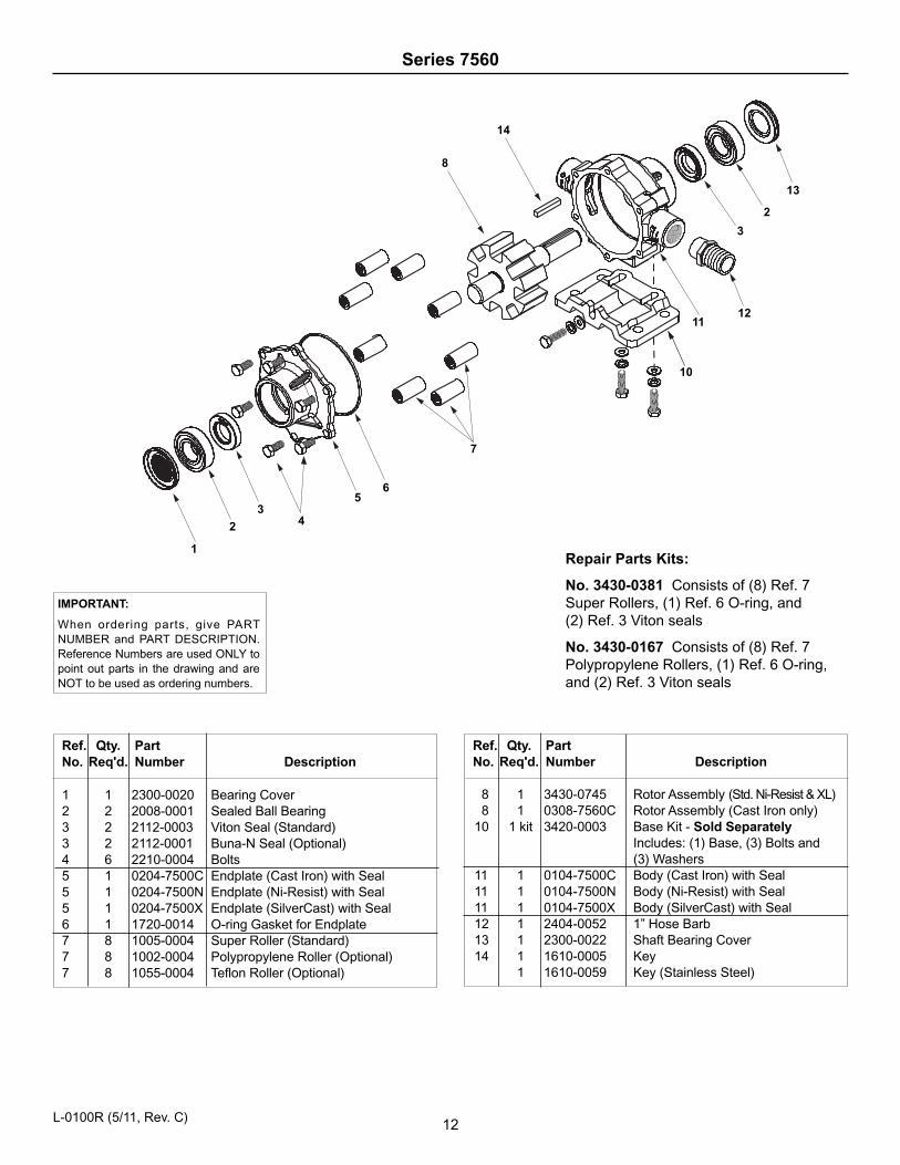
Series 7560
Repair Parts Kits:
No. 3430-0381 Consists of (8) Ref. 7Super Rollers, (1) Ref. 6 O-ring, and(2) Ref. 3 Viton seals
No. 3430-0167 Consists of (8) Ref. 7Polypropylene Rollers, (1) Ref. 6 O-ring,and (2) Ref. 3 Viton seals
Ref. Qty. PartNo. Req'd. Number Description
1 1 2300-0020 Bearing Cover2 2 2008-0001 Sealed Ball Bearing3 2 2112-0003 Viton Seal (Standard)3 2 2112-0001 Buna-N Seal (Optional)4 6 2210-0004 Bolts5 1 0204-7500C Endplate (Cast Iron) with Seal5 1 0204-7500N Endplate (Ni-Resist) with Seal5 1 0204-7500X Endplate (SilverCast) with Seal6 1 1720-0014 O-ring Gasket for Endplate7 8 1005-0004 Super Roller (Standard)7 8 1002-0004 Polypropylene Roller (Optional)7 8 1055-0004 Teflon Roller (Optional)
Ref. Qty. PartNo. Req'd. Number Description
8 1 3430-0745 Rotor Assembly (Std. Ni-Resist & XL)8 1 0308-7560C Rotor Assembly (Cast Iron only)
10 1 kit 3420-0003 Base Kit - Sold SeparatelyIncludes: (1) Base, (3) Bolts and(3) Washers
11 1 0104-7500C Body (Cast Iron) with Seal11 1 0104-7500N Body (Ni-Resist) with Seal11 1 0104-7500X Body (SilverCast) with Seal12 1 2404-0052 1” Hose Barb13 1 2300-0022 Shaft Bearing Cover14 1 1610-0005 Key
1 1610-0059 Key (Stainless Steel)
IMPORTANT:
When ordering parts, give PARTNUMBER and PART DESCRIPTION.Reference Numbers are used ONLY topoint out parts in the drawing and areNOT to be used as ordering numbers.
2
3
1211
10
7
1
2
34
56
13
14
8
L-0100R (5/11, Rev. C)
13
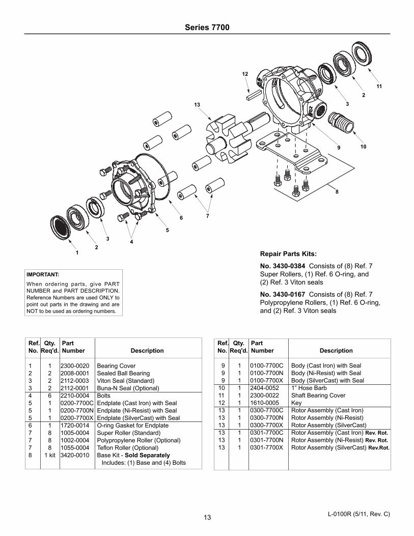
Series 7700
Repair Parts Kits:
No. 3430-0384 Consists of (8) Ref. 7Super Rollers, (1) Ref. 6 O-ring, and(2) Ref. 3 Viton seals
No. 3430-0167 Consists of (8) Ref. 7Polypropylene Rollers, (1) Ref. 6 O-ring,and (2) Ref. 3 Viton seals
Ref. Qty. PartNo. Req'd. Number Description
1 1 2300-0020 Bearing Cover2 2 2008-0001 Sealed Ball Bearing3 2 2112-0003 Viton Seal (Standard)3 2 2112-0001 Buna-N Seal (Optional)4 6 2210-0004 Bolts5 1 0200-7700C Endplate (Cast Iron) with Seal5 1 0200-7700N Endplate (Ni-Resist) with Seal5 1 0200-7700X Endplate (SilverCast) with Seal6 1 1720-0014 O-ring Gasket for Endplate7 8 1005-0004 Super Roller (Standard)7 8 1002-0004 Polypropylene Roller (Optional)7 8 1055-0004 Teflon Roller (Optional)8 1 kit 3420-0010 Base Kit - Sold Separately
Includes: (1) Base and (4) Bolts
Ref. Qty. PartNo. Req'd. Number Description
9 1 0100-7700C Body (Cast Iron) with Seal9 1 0100-7700N Body (Ni-Resist) with Seal9 1 0100-7700X Body (SilverCast) with Seal
10 1 2404-0052 1” Hose Barb11 1 2300-0022 Shaft Bearing Cover12 1 1610-0005 Key13 1 0300-7700C Rotor Assembly (Cast Iron)13 1 0300-7700N Rotor Assembly (Ni-Resist)13 1 0300-7700X Rotor Assembly (SilverCast)13 1 0301-7700C Rotor Assembly (Cast Iron) Rev. Rot.13 1 0301-7700N Rotor Assembly (Ni-Resist) Rev. Rot.13 1 0301-7700X Rotor Assembly (SilverCast) Rev.Rot.
IMPORTANT:
When ordering parts, give PARTNUMBER and PART DESCRIPTION.Reference Numbers are used ONLY topoint out parts in the drawing and areNOT to be used as ordering numbers.
13
12
12
7
9
8
11
3
10
2
6
5
43
L-0100R (5/11, Rev. C)
3
4
56
16
9
14
8
10
13
7A
2
312
117
9
810
215
1
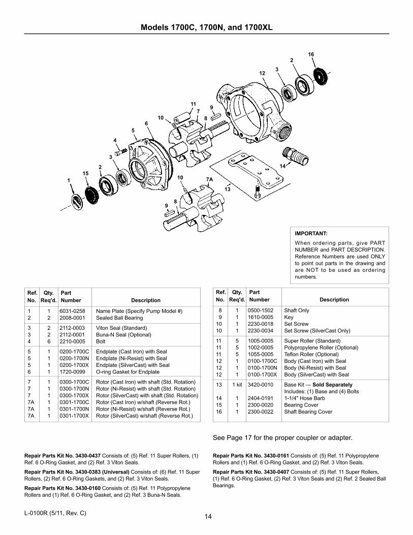
See Page 17 for the proper coupler or adapter.
Repair Parts Kit No. 3430-0437 Consists of: (5) Ref. 11 Super Rollers, (1)Ref. 6 O-Ring Gasket, and (2) Ref. 3 Viton Seals.
Repair Parts Kit No. 3430-0383 (Universal) Consists of: (6) Ref. 11 SuperRollers, (2) Ref. 6 O-Ring Gaskets, and (2) Ref. 3 Viton Seals.
Repair Parts Kit No. 3430-0160 Consists of: (5) Ref. 11 PolypropyleneRollers and (1) Ref. 6 O-Ring Gasket, and (2) Ref. 3 Buna-N Seals.
8 1 0500-1502 Shaft Only9 1 1610-0005 Key
10 1 2230-0018 Set Screw10 1 2230-0034 Set Screw (SilverCast Only)
11 5 1005-0005 Super Roller (Standard)11 5 1002-0005 Polypropylene Roller (Optional) 11 5 1055-0005 Teflon Roller (Optional)12 1 0100-1700C Body (Cast Iron) with Seal12 1 0100-1700N Body (Ni-Resist) with Seal12 1 0100-1700X Body (SilverCast) with Seal
13 1 kit 3420-0010 Base Kit — Sold SeparatelyIncludes: (1) Base and (4) Bolts
14 1 2404-0191 1-1/4" Hose Barb15 1 2300-0020 Bearing Cover16 1 2300-0022 Shaft Bearing Cover
1 1 6031-0258 Name Plate (Specify Pump Model #)2 2 2008-0001 Sealed Ball Bearing
3 2 2112-0003 Viton Seal (Standard)3 2 2112-0001 Buna-N Seal (Optional)4 6 2210-0005 Bolt
5 1 0200-1700C Endplate (Cast Iron) with Seal5 1 0200-1700N Endplate (Ni-Resist) with Seal5 1 0200-1700X Endplate (SilverCast) with Seal6 1 1720-0099 O-ring Gasket for Endplate
7 1 0300-1700C Rotor (Cast Iron) with shaft (Std. Rotation)7 1 0300-1700N Rotor (Ni-Resist) with shaft (Std. Rotation)7 1 0300-1700X Rotor (SilverCast) with shaft (Std. Rotation)7A 1 0301-1700C Rotor (Cast Iron) w/shaft (Reverse Rot.)7A 1 0301-1700N Rotor (Ni-Resist) w/shaft (Reverse Rot.)7A 1 0301-1700X Rotor (SilverCast) w/shaft (Reverse Rot.)
Ref. Qty. PartNo. Req'd. Number Description
Ref. Qty. PartNo. Req'd. Number Description
IMPORTANT:
When ordering parts, give PARTNUMBER and PART DESCRIPTION.Reference Numbers are used ONLYto point out parts in the drawing andare NOT to be used as orderingnumbers.
Repair Parts Kit No. 3430-0161 Consists of: (5) Ref. 11 PolypropyleneRollers and (1) Ref. 6 O-Ring Gasket, and (2) Ref. 3 Viton Seals.
Repair Parts Kit No. 3430-0407 Consists of: (5) Ref. 11 Super Rollers,(1) Ref. 6 O-Ring Gasket, (2) Ref. 3 Viton Seals and (2) Ref. 2 Sealed BallBearings.
Models 1700C, 1700N, and 1700XL
14L-0100R (5/11, Rev. C)
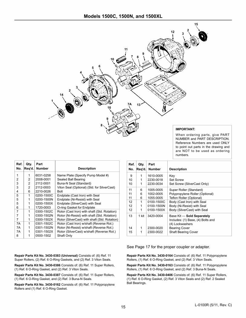
15
IMPORTANT:
When ordering parts, give PARTNUMBER and PART DESCRIPTION.Reference Numbers are used ONLYto point out parts in the drawing andare NOT to be used as orderingnumbers.
See Page 17 for the proper coupler or adapter.
15
23
12
13
987
11
10
8
9
107A
65
4
32
14
1
Repair Parts Kit No. 3430-0164 Consists of: (6) Ref. 11 PolypropyleneRollers, (1) Ref. 6 O-Ring Gasket, and (2) Ref. 3 Viton Seals.
Repair Parts Kit No. 3430-0163 Consists of: (6) Ref. 11 PolypropyleneRollers, (1) Ref. 6 O-Ring Gasket, and (2) Ref. 3 Buna-N Seals.
Repair Parts Kit No. 3430-0406 Consists of: (6) Ref. 11 Super Rollers,(1) Ref. 6 O-Ring Gasket, (2) Ref. 3 Viton Seals and (2) Ref. 2 SealedBall Bearings.
9 1 1610-0005 Key10 1 2230-0018 Set Screw10 1 2230-0034 Set Screw (SilverCast Only)
11 6 1005-0005 Super Roller (Standard)11 6 1002-0005 Polypropylene Roller (Optional) 11 6 1055-0005 Teflon Roller (Optional)12 1 0100-1500C Body (Cast Iron) with Seal12 1 0100-1500N Body (Ni-Resist) with Seal12 1 0100-1500X Body (SilverCast) with Seal
13 1 kit 3420-0004 Base Kit — Sold SeparatelyIncludes: (1) Base, (4) Bolts and (4) Lockwashers
14 1 2300-0020 Bearing Cover15 1 2300-0022 Shaft Bearing Cover
Ref. Qty. Part
No. Req'd. Number Description
1 1 6031-0258 Name Plate (Specify Pump Model #)2 2 2008-0001 Sealed Ball Bearing 3 2 2112-0001 Buna-N Seal (Standard)3 2 2112-0003 Viton Seal (Optional) (Std. for SilverCast)4 6 2210-0026 Bolt5 1 0200-1500C Endplate (Cast Iron) with Seal5 1 0200-1500N Endplate (Ni-Resist) with Seal5 1 0200-1500X Endplate (SilverCast) with Seal6 1 1720-0003 O-ring Gasket for Endplate7 1 0300-1502C Rotor (Cast Iron) with shaft (Std. Rotation)7 1 0300-1502N Rotor (Ni-Resist) with shaft (Std. Rotation)7 1 0300-1502X Rotor (SilverCast) with shaft (Std. Rotation)7A 1 0301-1502C Rotor (Cast Iron) w/shaft (Reverse Rot.)7A 1 0301-1502N Rotor (Ni-Resist) w/shaft (Reverse Rot.)7A 1 0301-1502X Rotor (SilverCast) w/shaft (Reverse Rot.)8 1 0500-1502 Shaft Only
Ref. Qty. PartNo. Req'd. Number Description
Repair Parts Kit No. 3430-0383 (Universal) Consists of: (6) Ref. 11Super Rollers, (2) Ref. 6 O-Ring Gaskets, and (2) Ref. 3 Viton Seals.
Repair Parts Kit No. 3430-0386 Consists of: (6) Ref. 11 Super Rollers,(1) Ref. 6 O-Ring Gasket, and (2) Ref. 3 Viton Seals.
Repair Parts Kit No. 3430-0387 Consists of: (6) Ref. 11 Super Rollers,(1) Ref. 6 O-Ring Gasket, and (2) Ref. 3 Buna-N Seals.
Repair Parts Kit No. 3430-0162 Consists of: (6) Ref. 11 PolypropyleneRollers and (1) Ref. 6 O-Ring Gasket.
Models 1500C, 1500N, and 1500XL
L-0100R (5/11, Rev. C)
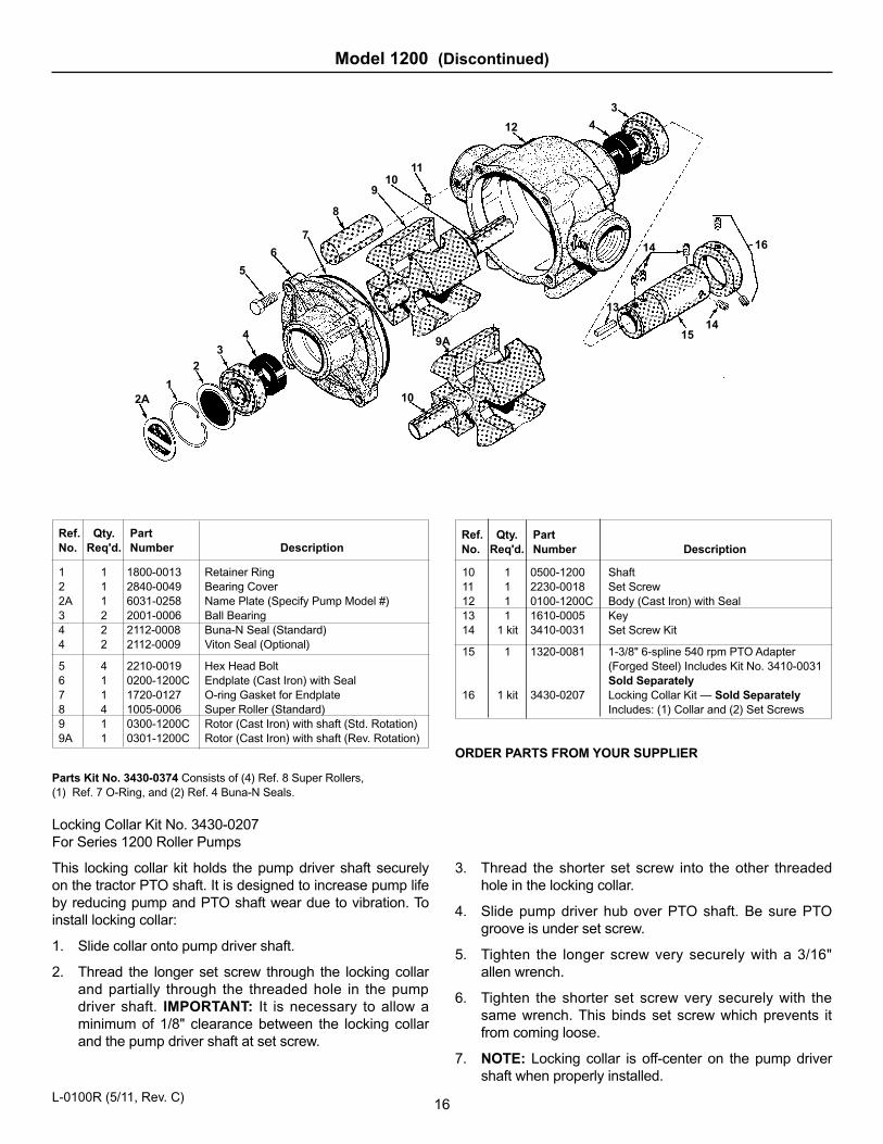
Locking Collar Kit No. 3430-0207For Series 1200 Roller Pumps
This locking collar kit holds the pump driver shaft securelyon the tractor PTO shaft. It is designed to increase pump lifeby reducing pump and PTO shaft wear due to vibration. Toinstall locking collar:
1. Slide collar onto pump driver shaft.
2. Thread the longer set screw through the locking collarand partially through the threaded hole in the pumpdriver shaft. IMPORTANT: It is necessary to allow aminimum of 1/8" clearance between the locking collarand the pump driver shaft at set screw.
3. Thread the shorter set screw into the other threadedhole in the locking collar.
4. Slide pump driver hub over PTO shaft. Be sure PTOgroove is under set screw.
5. Tighten the longer screw very securely with a 3/16"allen wrench.
6. Tighten the shorter set screw very securely with thesame wrench. This binds set screw which prevents itfrom coming loose.
7. NOTE: Locking collar is off-center on the pump drivershaft when properly installed.
10 1 0500-1200 Shaft11 1 2230-0018 Set Screw12 1 0100-1200C Body (Cast Iron) with Seal13 1 1610-0005 Key14 1 kit 3410-0031 Set Screw Kit
15 1 1320-0081 1-3/8" 6-spline 540 rpm PTO Adapter(Forged Steel) Includes Kit No. 3410-0031Sold Separately
16 1 kit 3430-0207 Locking Collar Kit — Sold SeparatelyIncludes: (1) Collar and (2) Set Screws
ORDER PARTS FROM YOUR SUPPLIER
Parts Kit No. 3430-0374 Consists of (4) Ref. 8 Super Rollers,(1) Ref. 7 O-Ring, and (2) Ref. 4 Buna-N Seals.
Ref. Qty. PartNo. Req'd. Number Description
Ref. Qty. PartNo. Req'd. Number Description
1 1 1800-0013 Retainer Ring2 1 2840-0049 Bearing Cover2A 1 6031-0258 Name Plate (Specify Pump Model #)3 2 2001-0006 Ball Bearing4 2 2112-0008 Buna-N Seal (Standard)4 2 2112-0009 Viton Seal (Optional)
5 4 2210-0019 Hex Head Bolt6 1 0200-1200C Endplate (Cast Iron) with Seal7 1 1720-0127 O-ring Gasket for Endplate8 4 1005-0006 Super Roller (Standard)9 1 0300-1200C Rotor (Cast Iron) with shaft (Std. Rotation)9A 1 0301-1200C Rotor (Cast Iron) with shaft (Rev. Rotation)
Model 1200 (Discontinued)
16
2A1
23
49A
15
1614
13
14
10
8
910
11
12 4
3
7
6
5
L-0100R (5/11, Rev. C)
17
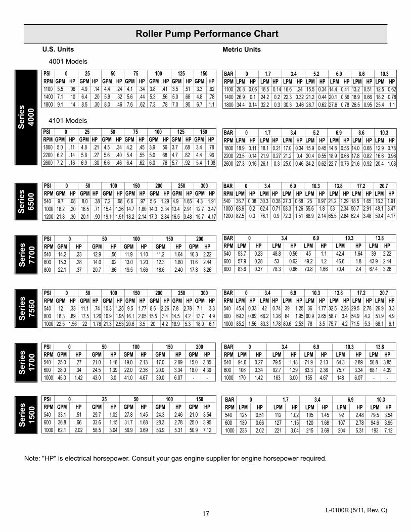
Note: "HP" is electrical horsepower. Consult your gas engine supplier for engine horsepower required.
PSI 0 25 50 100 150RPM GPM HP GPM HP GPM HP GPM HP GPM HP540 33.1 .51 29.7 1.02 27.8 1.45 24.3 2.46 21.0 3.54600 36.8 .66 33.6 1.15 31.7 1.68 28.3 2.78 25.0 3.951000 62.1 2.02 58.5 3.04 56.9 3.69 53.9 5.31 50.9 7.12
BAR 0 3.4 6.9 10.3 13.8 17.2 20.7RPM LPM HP LPM HP LPM HP LPM HP LPM HP LPM HP LPM HP540 36.7 0.08 30.3 0.38 27.3 0.68 25 0.97 21.2 1.29 18.5 1.65 16.3 1.911000 68.9 0.2 62.4 0.71 58.3 1.26 55.6 1.8 53 2.34 50.7 2.91 48.1 3.471200 82.5 0.3 76.1 0.9 72.3 1.51 68.9 2.14 65.5 2.84 62.4 3.48 59.4 4.17
BAR 0 3.4 6.9 10.3 13.8RPM LPM HP LPM HP LPM HP LPM HP LPM HP540 53.7 0.23 48.8 0.56 45 1.1 42.4 1.64 39 2.22600 57.9 0.28 53 0.62 49.2 1.2 46.6 1.8 43.9 2.44800 83.6 0.37 78.3 0.86 73.8 1.66 70.4 2.4 67.4 3.26
PSI 0 25 50 75 100 125 150RPM GPM HP GPM HP GPM HP GPM HP GPM HP GPM HP GPM HP1100 5.5 .06 4.9 .14 4.4 .24 4.1 .34 3.8 .41 3.5 .51 3.3 .621400 7.1 .10 6.4 .20 5.9 .32 5.6 .44 5.3 .56 5.0 .68 4.8 .781800 9.1 .14 8.5 .30 8.0 .46 7.6 .62 7.3 .78 7.0 .95 6.7 1.1
4101 Models
PSI 0 25 50 75 100 125 150RPM GPM HP GPM HP GPM HP GPM HP GPM HP GPM HP GPM HP1800 5.0 .11 4.8 .21 4.5 .34 4.2 .45 3.9 .56 3.7 .68 3.4 .782200 6.2 .14 5.8 .27 5.6 .40 5.4 .55 5.0 .68 4.7 .82 4.4 .962600 7.2 .16 6.9 .30 6.6 .46 6.4 .62 6.0 .76 5.7 .92 5.4 1.08
Ser
ies
6500
Ser
ies
7700
Ser
ies
7560
Ser
ies
1700
Ser
ies
1500
PSI 0 50 100 150 200RPM GPM HP GPM HP GPM HP GPM HP GPM HP540 25.0 .27 21.0 1.18 19.0 2.13 17.0 2.89 15.0 3.85600 28.0 .34 24.5 1.39 22.0 2.36 20.0 3.34 18.0 4.391000 45.0 1.42 43.0 3.0 41.0 4.67 39.0 6.07 - -
PSI 0 50 100 150 200RPM GPM HP GPM HP GPM HP GPM HP GPM HP540 14.2 .23 12.9 .56 11.9 1.10 11.2 1.64 10.3 2.22600 15.3 .28 14.0 .62 13.0 1.20 12.3 1.80 11.6 2.44800 22.1 .37 20.7 .86 19.5 1.66 18.6 2.40 17.8 3.26
BAR 0 1.7 3.4 5.2 6.9 8.6 10.3RPM LPM HP LPM HP LPM HP LPM HP LPM HP LPM HP LPM HP1800 18.9 0.11 18.1 0.21 17.0 0.34 15.9 0.45 14.8 0.56 14.0 0.68 12.9 0.782200 23.5 0.14 21.9 0.27 21.2 0.4 20.4 0.55 18.9 0.68 17.8 0.82 16.6 0.962600 27.3 0.16 26.1 0.3 25.0 0.46 24.2 0.62 22.7 0.76 21.6 0.92 20.4 1.08
BAR 0 1.7 3.4 5.2 6.9 8.6 10.3RPM LPM HP LPM HP LPM HP LPM HP LPM HP LPM HP LPM HP1100 20.8 0.06 18.5 0.14 16.6 .24 15.5 0.34 14.4 0.41 13.2 0.51 12.5 0.621400 26.9 0.1 24.2 0.2 22.3 0.32 21.2 0.44 20.1 0.56 18.9 0.66 18.2 0.781800 34.4 0.14 32.2 0.3 30.3 0.46 28.7 0.62 27.6 0.78 26.5 0.95 25.4 1.1
BAR 0 3.4 6.9 10.3 13.8 17.2 20.7RPM LPM HP LPM HP LPM HP LPM HP LPM HP LPM HP LPM HP540 45.4 0.33 42 0.74 39 1.25 36 1.77 32.5 2.26 29.5 2.78 26.9 3.3800 69.3 0.89 66.2 1.26 64 1.95 60.9 2.65 58.7 3.4 54.9 4.2 51.9 4.91000 85.2 1.56 83.3 1.78 80.6 2.53 78 3.5 75.7 4.2 71.5 5.3 68.1 6.1
BAR 0 3.4 6.9 10.3 13.8RPM LPM HP LPM HP LPM HP LPM HP LPM HP540 94.6 0.27 79.5 1.18 71.9 2.13 64.3 2.89 56.8 3.85600 106 0.34 92.7 1.39 83.3 2.36 75.7 3.34 68.1 4.391000 170 1.42 163 3.00 155 4.67 148 6.07 - -
BAR 0 1.7 3.4 6.9 10.3RPM LPM HP LPM HP LPM HP LPM HP LPM HP540 125 0.51 112 1.02 105 1.45 92 2.48 79.5 3.54600 139 0.66 127 1.15 120 1.68 107 2.78 94.6 3.951000 235 2.02 221 3.04 215 3.69 204 5.31 193 7.12
Metric UnitsU.S. Units
4001 Models
PSI 0 50 100 150 200 250 300RPM GPM HP GPM HP GPM HP GPM HP GPM HP GPM HP GPM HP540 9.7 .08 8.0 .38 7.2 .68 6.6 .97 5.6 1.29 4.9 1.65 4.3 1.911000 18.2 .20 16.5 .71 15.4 1.26 14.7 1.80 14.0 2.34 13.4 2.91 12.7 3.471200 21.8 .30 20.1 .90 19.1 1.51 18.2 2.14 17.3 2.84 16.5 3.48 15.7 4.17
PSI 0 50 100 150 200 250 300RPM GPM HP GPM HP GPM HP GPM HP GPM HP GPM HP GPM HP540 12 .33 11.1 .74 10.3 1.25 9.5 1.77 8.6 2.26 7.8 2.78 7.1 3.3800 18.3 .89 17.5 1.26 16.9 1.95 16.1 2.65 15.5 3.4 14.5 4.2 13.7 4.91000 22.5 1.56 22 1.78 21.3 2.53 20.6 3.5 20 4.2 18.9 5.3 18.0 6.1
Ser
ies
4000
Roller Pump Performance Chart
L-0100R (5/11, Rev. C)
18
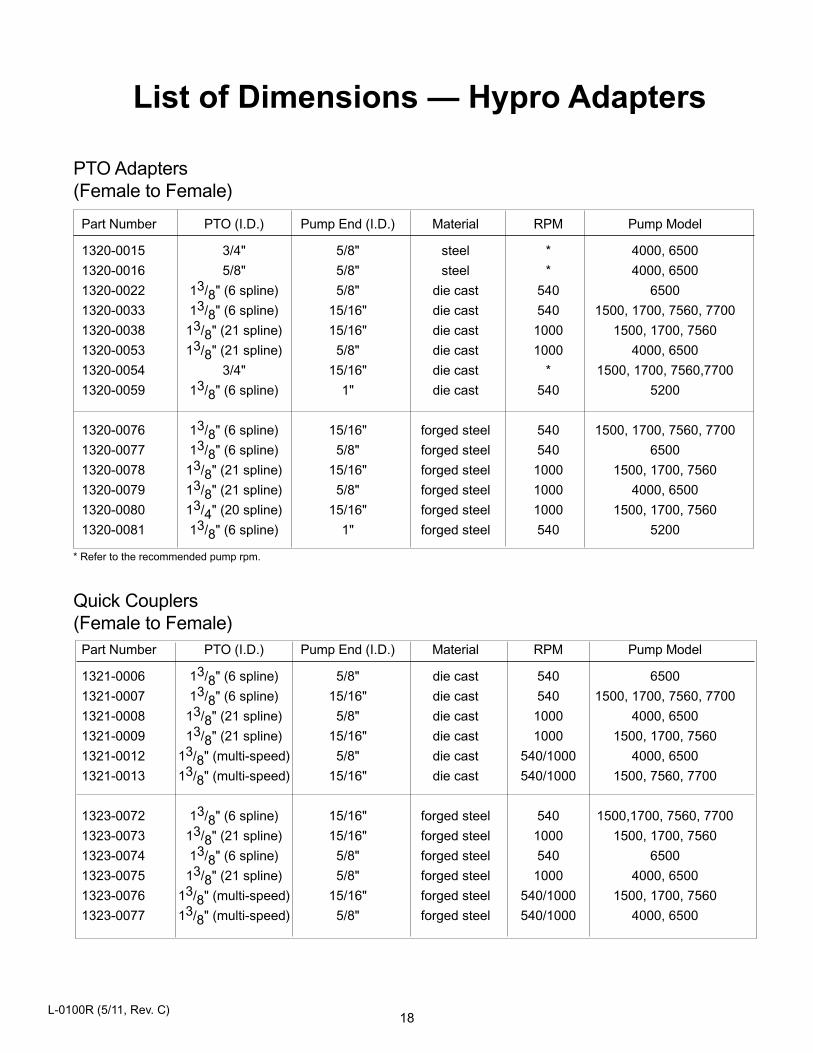
Part Number PTO (I.D.) Pump End (I.D.) Material RPM Pump Model
1320-0015 3/4" 5/8" steel * 4000, 6500
1320-0016 5/8" 5/8" steel * 4000, 6500
1320-0022 13/8" (6 spline) 5/8" die cast 540 6500
1320-0033 13/8" (6 spline) 15/16" die cast 540 1500, 1700, 7560, 7700
1320-0038 13/8" (21 spline) 15/16" die cast 1000 1500, 1700, 7560
1320-0053 13/8" (21 spline) 5/8" die cast 1000 4000, 6500
1320-0054 3/4" 15/16" die cast * 1500, 1700, 7560,7700
1320-0059 13/8" (6 spline) 1" die cast 540 5200
1320-0076 13/8" (6 spline) 15/16" forged steel 540 1500, 1700, 7560, 7700
1320-0077 13/8" (6 spline) 5/8" forged steel 540 6500
1320-0078 13/8" (21 spline) 15/16" forged steel 1000 1500, 1700, 7560
1320-0079 13/8" (21 spline) 5/8" forged steel 1000 4000, 6500
1320-0080 13/4" (20 spline) 15/16" forged steel 1000 1500, 1700, 7560
1320-0081 13/8" (6 spline) 1" forged steel 540 5200
Part Number PTO (I.D.) Pump End (I.D.) Material RPM Pump Model
1321-0006 13/8" (6 spline) 5/8" die cast 540 6500
1321-0007 13/8" (6 spline) 15/16" die cast 540 1500, 1700, 7560, 7700
1321-0008 13/8" (21 spline) 5/8" die cast 1000 4000, 6500
1321-0009 13/8" (21 spline) 15/16" die cast 1000 1500, 1700, 7560
1321-0012 13/8" (multi-speed) 5/8" die cast 540/1000 4000, 6500
1321-0013 13/8" (multi-speed) 15/16" die cast 540/1000 1500, 7560, 7700
1323-0072 13/8" (6 spline) 15/16" forged steel 540 1500,1700, 7560, 7700
1323-0073 13/8" (21 spline) 15/16" forged steel 1000 1500, 1700, 7560
1323-0074 13/8" (6 spline) 5/8" forged steel 540 6500
1323-0075 13/8" (21 spline) 5/8" forged steel 1000 4000, 6500
1323-0076 13/8" (multi-speed) 15/16" forged steel 540/1000 1500, 1700, 7560
1323-0077 13/8" (multi-speed) 5/8" forged steel 540/1000 4000, 6500
Quick Couplers(Female to Female)
List of Dimensions — Hypro Adapters
PTO Adapters(Female to Female)
* Refer to the recommended pump rpm.
L-0100R (5/11, Rev. C)
19
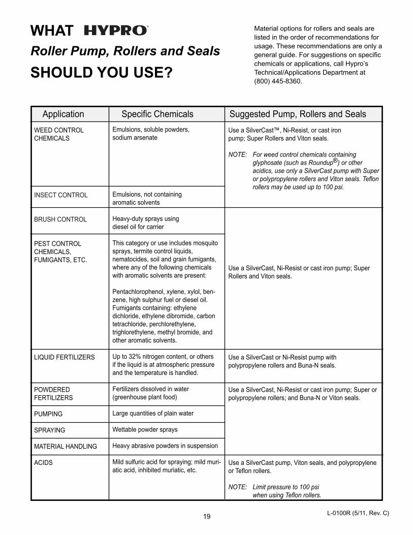
Use a SilverCast™, Ni-Resist, or cast iron pump; Super Rollers and Viton seals.
NOTE: For weed control chemicals containingglyphosate (such as Roundup®) or otheracidics, use only a SilverCast pump with Superor polypropylene rollers and Viton seals. Teflonrollers may be used up to 100 psi.
Use a SilverCast, Ni-Resist or cast iron pump; SuperRollers and Viton seals.
Use a SilverCast or Ni-Resist pump with polypropylene rollers and Buna-N seals.
Use a SilverCast, Ni-Resist or cast iron pump; Super orpolypropylene rollers; and Buna-N or Viton seals.
Use a SilverCast pump, Viton seals, and polypropyleneor Teflon rollers.
NOTE: Limit pressure to 100 psi when using Teflon rollers.
WEED CONTROLCHEMICALS
INSECT CONTROL
BRUSH CONTROL
PEST CONTROLCHEMICALS, FUMIGANTS, ETC.
LIQUID FERTILIZERS
POWDEREDFERTILIZERS
PUMPING
SPRAYING
MATERIAL HANDLING
ACIDS
Emulsions, soluble powders, sodium arsenate
Emulsions, not containing aromatic solvents
Heavy-duty sprays using diesel oil for carrier
This category or use includes mosquitosprays, termite control liquids, nematocides, soil and grain fumigants,where any of the following chemicalswith aromatic solvents are present:
Pentachlorophenol, xylene, xylol, ben-zene, high sulphur fuel or diesel oil.Fumigants containing: ethylene dichloride, ethylene dibromide, carbontetrachloride, perchlorethylene,trighlorethylene, methyl bromide, andother aromatic solvents.
Up to 32% nitrogen content, or others if the liquid is at atmospheric pressure and the temperature is handled.
Fertilizers dissolved in water (greenhouse plant food)
Large quantities of plain water
Wettable powder sprays
Heavy abrasive powders in suspension
Mild sulfuric acid for spraying; mild muri-atic acid, inhibited muriatic, etc.
Application Specific Chemicals Suggested Pump, Rollers and Seals
Material options for rollers and seals arelisted in the order of recommendations forusage. These recommendations are only ageneral guide. For suggestions on specificchemicals or applications, call Hypro’sTechnical/Applications Department at(800) 445-8360.
WHAT Roller Pump, Rollers and Seals
SHOULD YOU USE?
L-0100R (5/11, Rev. C)
Hypro/SHURflo (hereafter, “Hypro”) agricultural products are warranted to be free of defects in material and workmanship undernormal use for the time periods listed below, with proof of purchase.
- Pumps: one (1) year from the date of manufacture, or one (1) year of use. This limited warranty will notexceed two (2) years, in any event.
- Accessories: ninety (90) days of use.
This limited warranty will not apply to products that were improperly installed, misapplied, damaged, altered, or incompatible withfluids or components not manufactured by Hypro. All warranty considerations are governed by Hypro’s written return policy.
Hypro’s obligation under this limited warranty policy is limited to the repair or replacement of the product. All returns will be testedper Hypro’s factory criteria. Products found not defective (under the terms of this limited warranty) are subject to charges paid by thereturnee for the testing and packaging of “tested good” non-warranty returns.
No credit or labor allowances will be given for products returned as defective. Warranty replacement will be shipped on a freight allowedbasis. Hypro reserves the right to choose the method of transportation.
This limited warranty is in lieu of all other warranties, expressed or implied, and no other person is authorized to give any otherwarranty or assume obligation or liability on Hypro’s behalf. Hypro shall not be liable for any labor, damage or other expense, nor shallHypro be liable for any indirect, incidental or consequential damages of any kind incurred by the reason of the use or sale ofany defective product. This limited warranty covers agricultural products distributed within the United States of America. Other world marketareas should consult with the actual distributor for any deviation from this document.
Return ProceduresAll products must be flushed of any chemical (ref. OSHA section 1910.1200 (d) (e) (f) (g) (h)) and hazardous chemicals must belabeled/tagged before being shipped* to Hypro for service or warranty consideration. Hypro reserves the right to request a Material SafetyData Sheet from the returnee for any pump/product it deems necessary. Hypro reserves the right to “disposition as scrap” products returnedwhich contain unknown fluids. Hypro reserves the right to charge the returnee for any and all costs incurred for chemical testing, and properdisposal of components containing unknown fluids. Hypro requests this in order to protect the environment and personnel from the hazardsof handling unknown fluids.
Be prepared to give Hypro full details of the problem, including the model number, date of purchase, and from whom you purchased yourproduct. Hypro may request additional information, and may require a sketch to illustrate the problem.
Contact Hypro Service Department at 800-468-3428 to receive a Return Merchandise Authorization number (RMA#).Returns are to be shipped with the RMA number clearly marked on the outside of the package. Hypro shall not be liable for freight damageincurred during shipping. Please package all returns carefully. All products returned for warranty work should be sent shipping chargesprepaid to:
HYPROAttention: Service Department375 Fifth Avenue NWNew Brighton, MN 55112
For technical or application assistance, call the Hypro Technical/Application number: 800-445-8360, or send an email to:[email protected]. To obtain service or warranty assistance, call the Hypro Service and Warranty number: 800-468-3428;or send a fax to the Hypro Service and Warranty FAX: 651-766-6618.
*Carriers, including U.S.P.S., airlines, UPS, ground freight, etc., require specific identification of any hazardous material being shipped. Failure to do so mayresult in a substantial fine and/or prison term. Check with your shipping company for specific instructions.
Printed in the USA2011 Hypro
Limited Warranty on Hypro/SHURflo Agricultural Pumps & Accessories
SPRAY & INJECTION TECHNOLOGIES GROUP375 Fifth Avenue NW • New Brighton, MN 55112Phone: (651) 766-6300 • 800-424-9776 • Fax: 800-323-6496www.hypropumps.com