Embed Size (px)
Citation preview
Rolling Bearing Mountings for Converters


Contents 1 Requirements on the trunnion bearings in converters 2
2 Rolling bearings and housings for converters 32.1 Spherical roller bearings 32.2 Split spherical roller bearings 52.3 Housing KPG49 62.4 Housing KPGZ49 7
3 Dimensioning of rolling bearings 83.1 Static load safety factor 83.2 Dimensioning with BEARINX® 8
4 Design of adjacent parts 104.1 Fits 104.2 Seals 10
5 Mounting, lubrication and maintenance 115.1 Preparations for fitting 115.2 Fitting of unsplit bearings 115.3 Fitting of split bearings 135.4 Measures to be taken after fitting 175.5 Lubrication 195.6 Maintenance 195.7 Dismantling 205.8 Maintenance forms 20
6 Dimension tables for rolling bearings and housings for converters 27
6.1 Spherical roller bearings 286.2 Split spherical roller bearings 326.3 Housing KPG49 366.4 Housing KPGZ49 40
7 References 44
8 Other publications 44
9 Design brief 45
1
1 Requirements on the trunnion bearings in converters
When filled, large converter vesselsweigh several hundred tons. The resulting loads must be supported by the trunnion bearingarrangement. As only slow swivelmotions occur, the bearings mustfeature a high static load carryingcapacity. Shock loads, which are aneveryday occurrence in converters,must also be accommodated.
The bearing arrangement must alsobe able to compensate housingmisalignments and deflections ofthe construction. In addition, considerable length variationscaused by the temperature changesduring heating and cooling of theconverter must be compensatedfor, as well as dimensional changesto the supporting ring.
The spherical roller bearing hasestablished itself as the rollingbearing type for converters. In addition to its high radial andaxial load carrying capacity and its insensitivity to shocks, it alsoprovides significant angularadjustability.
In the conventional design, the locating bearing on the drive side supports the axial guidanceforces of the converter. A plain bush,in which the bearing outer ring can shift axially, is inserted in thehousing on the non-locating bearingside, Figure 1.
Requirements on the trunnion bearings in converters
2
Spherical roller bearings featuringthe main dimensions of series 249meet the demands on converterbearings. These bearings haveproved to be particularly suitable in terms of axial displaceability.
Whereas unsplit bearings are usedon the non-locating bearing side,the preferred choice for replacementbearings on the locating bearingside are split spherical roller bearings whose dimensions arematched to series 249. The split bearings facilitate bearing replacement without dismountingthe drive, see section 2.2.
1: Trunnion bearing arrangement in a converter with two spherical roller bearings
Locating bearing Non-locating bearing
2 Rolling bearings andhousings for converters
The technical data relating to FAG spherical roller bearings and FAG plummer block housingsfor converters can be found in section 6.
2.1 Spherical roller bearings
The FAG spherical roller bearing is a rolling bearing designed forvery demanding conditions. It contains two rows of symmetricalbarrel rollers which orient themselves freely in the concaveouter ring raceway. As a result,shaft flexing and misalignment ofthe bearing seats are compensated.
FAG spherical roller bearings forconverters usually feature the main dimensions of the standardisedseries 249.
Bearing components are bonderisedand/or have a molybdenum disulphide coating, depending onthe design. The bearings are produced with a cylindrical or tapered bore (taper 1:30).
Spherical roller bearings with acylindrical bore are located directlyon the converter trunnion, Figure 1on page 2. Bearings with a taperedbore are mounted on taperedsleeves, Figure 2.
2.1.1 Aligning capability
Static angular misalignment
Over time, vertical or lateral offset of the housing can lead tomisalignments, Figure 3.
Rolling bearings and housings for convertersSpherical roller bearings
3
These so-called static angular misalignments are, for example,caused by subsidence of the foundations. The bearing is notsubjected to additional load provided that the rolling elementshave full length contact with theouter ring raceway. In the case ofall FAG spherical roller bearings for converters, the permissibleadjustment angle specified for static angular misalignment is 1,5°.
It has, however, been proven that astatic angular misalignment of just10' should be permitted whenmounting the housing. This value isset so low as it is anticipated thatthe position of the housing willincrease considerably over time dueto subsidence of the foundations orther mal influences.
α α
2: Spherical roller bearing as locating bearing on a sleeve 3: Static angular misalignment α
2 3
Dynamic angular misalignment
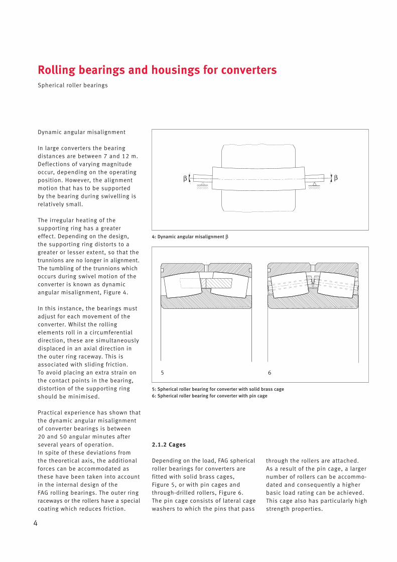
In large converters the bearing distances are between 7 and 12 m.Deflections of vary ing magnitudeoccur, depending on the operatingposition. However, the alignmentmotion that has to be supported by the bearing during swivelling isrelatively small.
The irregular heating of the supporting ring has a greatereffect. Depending on the design,the supporting ring distorts to agreater or lesser extent, so that thetrunnions are no longer in alignment.The tumbling of the trunnions whichoccurs during swivel motion of theconverter is known as dynamicangular misalignment, Figure 4.
In this instance, the bearings mustadjust for each movement of theconverter. Whilst the rolling elements roll in a circumferentialdirection, these are simultaneouslydisplaced in an axial direction inthe outer ring raceway. This is associated with sliding friction. To avoid placing an extra strain onthe contact points in the bearing,distortion of the supporting ringshould be minimised.
Practical experience has shown thatthe dynamic angular misalignmentof converter bearings is between 20 and 50 angular minutes afterseveral years of operation. In spite of these deviations fromthe theoretical axis, the additionalforces can be accommodated asthese have been taken into accountin the internal design of the FAG rolling bearings. The outer ring raceways or the rollers have a specialcoating which reduces friction.
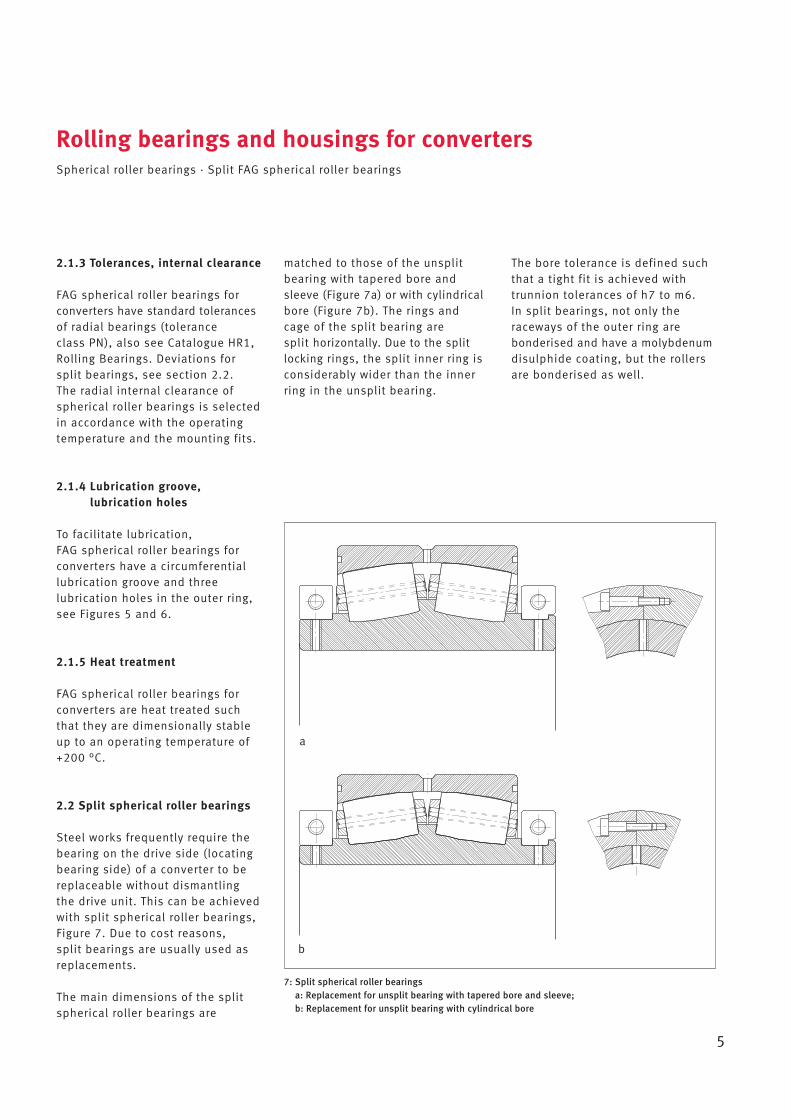
2.1.2 Cages
Depending on the load, FAG sphericalroller bearings for converters are fitted with solid brass cages, Figure 5, or with pin cages andthrough-drilled rollers, Figure 6. The pin cage consists of lateral cagewashers to which the pins that pass
Rolling bearings and housings for convertersSpherical roller bearings
4
through the rollers are attached. As a result of the pin cage, a largernumber of rollers can be accommo-dated and consequently a higherbasic load rating can be achieved.This cage also has particularly highstrength properties.
5: Spherical roller bearing for converter with solid brass cage6: Spherical roller bearing for converter with pin cage
4: Dynamic angular misalignment β
β β
5 6
2.1.3 Tolerances, internal clearance
FAG spherical roller bearings forconverters have standard tolerancesof radial bearings (tolerance class PN), also see Catalogue HR1,Rolling Bearings. Deviations forsplit bearings, see section 2.2. The radial internal clearance ofspherical roller bearings is selectedin accordance with the operating temperature and the mounting fits.
2.1.4 Lubrication groove, lubrication holes
To facilitate lubrication, FAG spherical roller bearings forconverters have a circumferentiallubrication groove and three lubrication holes in the outer ring,see Figures 5 and 6.
2.1.5 Heat treatment
FAG spherical roller bearings forconverters are heat treated suchthat they are dimensionally stableup to an operating temperature of+200 °C.
2.2 Split spherical roller bearings
Steel works frequently require thebearing on the drive side (locatingbearing side) of a converter to bereplaceable without dismantlingthe drive unit. This can be achievedwith split spherical roller bearings,Figure 7. Due to cost reasons, split bearings are usually used asreplacements.
The main dimensions of the splitspherical roller bearings are
matched to those of the unsplitbearing with tapered bore andsleeve (Figure 7a) or with cylindricalbore (Figure 7b). The rings andcage of the split bearing are split horizontally. Due to the splitlocking rings, the split inner ring isconsider ably wider than the innerring in the unsplit bearing.
Rolling bearings and housings for convertersSpherical roller bearings · Split FAG spherical roller bearings
5
The bore tolerance is defined suchthat a tight fit is achieved withtrunnion tolerances of h7 to m6. In split bearings, not only the raceways of the outer ring are bonderised and have a molybdenumdisulphide coating, but the rollersare bonderised as well.
7: Split spherical roller bearings a: Replacement for unsplit bearing with tapered bore and sleeve; b: Replacement for unsplit bearing with cylindrical bore
b
a
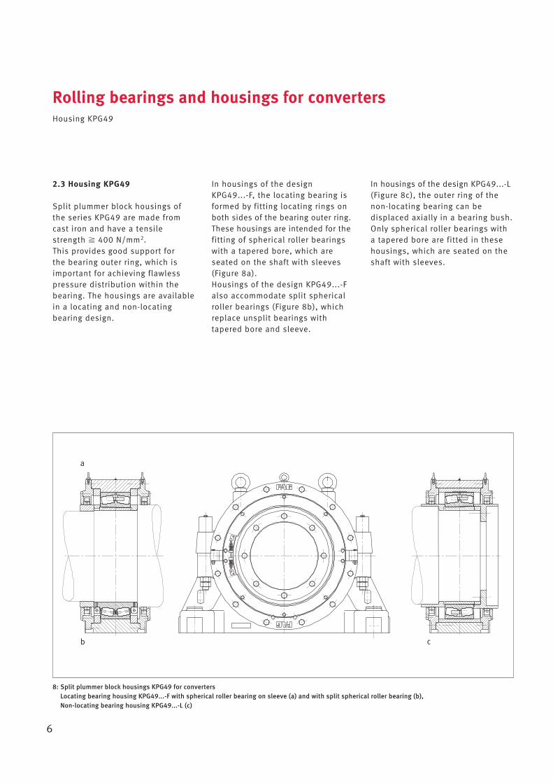
2.3 Housing KPG49
Split plummer block housings ofthe series KPG49 are made fromcast iron and have a tensilestrength � 400 N/mm2. This provides good support for the bearing outer ring, which isimportant for achieving flawlesspressure distribution within thebearing. The housings are availablein a locating and non-locating bearing design.
In housings of the design KPG49...-F, the locating bearing isformed by fitting locating rings onboth sides of the bearing outer ring.These housings are intended for thefitting of spherical roller bearingswith a tapered bore, which areseated on the shaft with sleeves(Figure 8a). Housings of the design KPG49...-Falso accommodate split sphericalroller bearings (Figure 8b), whichreplace unsplit bearings withtapered bore and sleeve.
Rolling bearings and housings for convertersHousing KPG49
6
In housings of the design KPG49...-L(Figure 8c), the outer ring of thenon-locating bearing can be displaced axially in a bearing bush.Only spherical roller bearings witha tapered bore are fitted in thesehousings, which are seated on theshaft with sleeves.
8: Split plummer block housings KPG49 for convertersLocating bearing housing KPG49...-F with spherical roller bearing on sleeve (a) and with split spherical roller bearing (b), Non-locating bearing housing KPG49...-L (c)
b
a
c
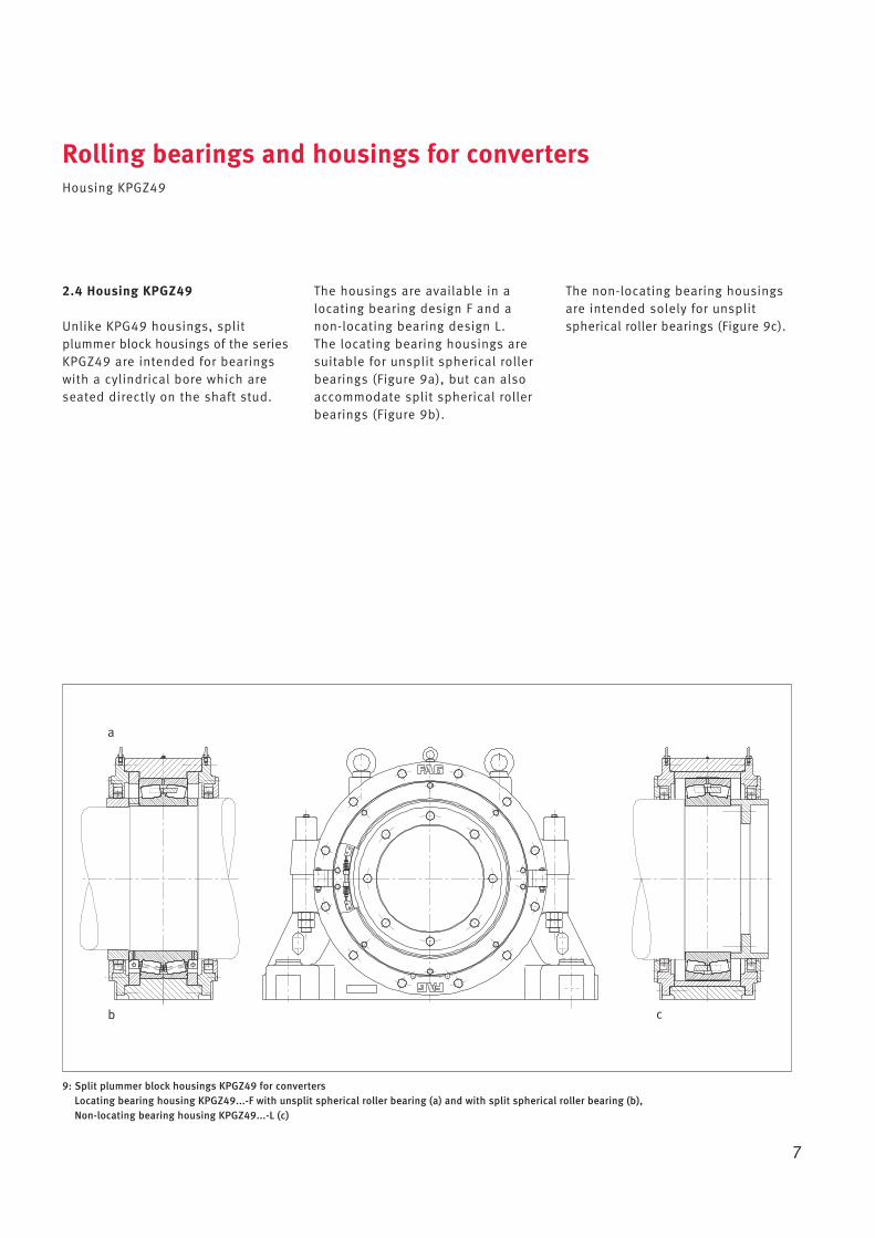
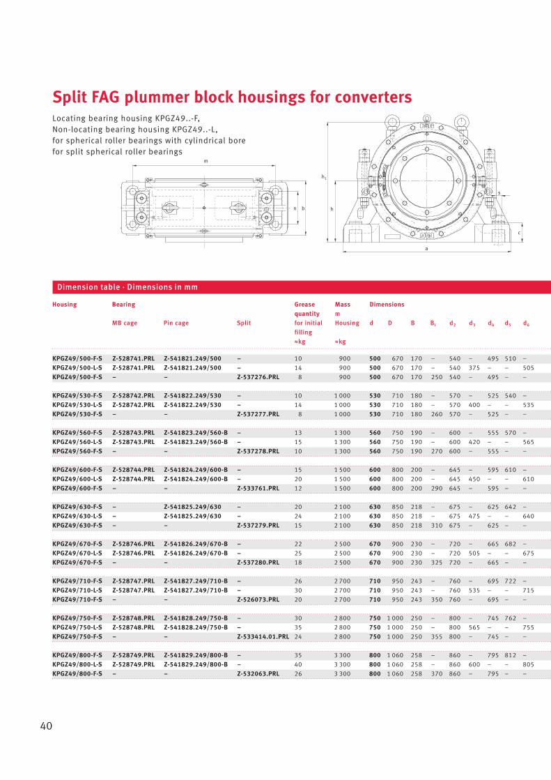
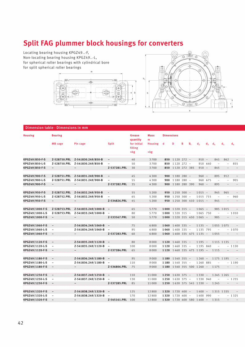
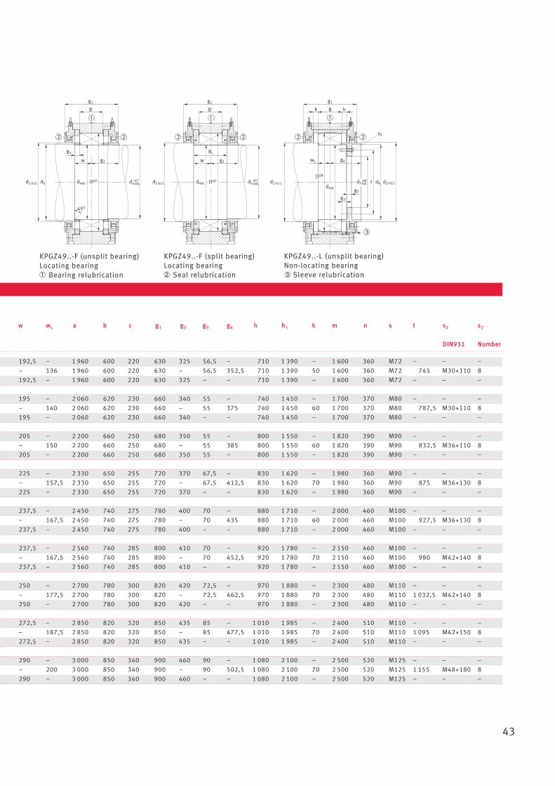
2.4 Housing KPGZ49
Unlike KPG49 housings, split plummer block housings of the seriesKPGZ49 are intended for bearingswith a cylindrical bore which areseated directly on the shaft stud.
The housings are available in alocating bearing design F and anon-locating bearing design L. The locating bearing housings aresuitable for unsplit spherical rollerbearings (Figure 9a), but can alsoaccommodate split spherical rollerbearings (Figure 9b).
Rolling bearings and housings for convertersHousing KPGZ49
7
The non-locating bearing housingsare intended solely for unsplitspherical roller bearings (Figure 9c).
9: Split plummer block housings KPGZ49 for convertersLocating bearing housing KPGZ49...-F with unsplit spherical roller bearing (a) and with split spherical roller bearing (b), Non-locating bearing housing KPGZ49...-L (c)
b
a
c
3 Dimensioning of rolling bearings
Converter bearings undergo swivelmotion and rotate up to 360° onlyoccasionally. The speed duringswivel motion is 0,1 to 1 rpm.
During decarburisation the converteris at rest, vibrations occur as aresult of the blowing process.
These conditions require bearingdimensioning that is based onstatic criteria.
The operating life of the bearings is determined by the wear period.Wear is caused by:• deflection
due to the large bearing distanceor deformation of the supportingring
• axial displacementdue to temperature changes inthe converter.
Wear can be reduced by phosphatising and/or adding amolybdenum disulphide coating to the bearing components.
3.1 Static load safety factor S0
For converter bearings, the requirement is normally
S0 � 2
A higher S0value means increasedoperational reliability. In particular,where load data has not been accurately defined, e.g. in the case of blowing process AOD, an S0 value � 2,5 should be aimed for.
S0 = C0r/P0
C0r basic static load rating [kN]from the bearing tables
P0 equivalent static load [kN]
Locating bearingP0F = F0rF + Y0 · (F0a + F0a1) [kN]
Non-locating bearingP0L = F0rL + Y0 · F0a1 [kN]
F0rF = maximum radial load for locating bearings [kN] *
F0rL = maximum radial load for non-locating bearings [kN] *
Y0 = axial factor (bearing tables)F0a = maximum external axial load
[kN] *F0a1 = μ · F0rL reaction force due
to non-locating bearing displacement [kN]
μ = 0,15 coefficient of frictionfor bush
* with possible shock loads
The results are entered in the calculation sheet (sheet B in section 5.8).
Dimensioning of rolling bearingsStatic load safety factor · Dimensioning with BEARINX®
8
3.2 Dimensioning with BEARINX®
The internal loads on the rollingbearings and the most importantcalculation results are generatednumerically and in graphs with theaid of our calculation program BEARINX®.
The following can be consideredinfluences:Shaft support in the form of bearings with non-linear elasticity(in detail, bearing geometry, bearing clearance, rolling elementand raceway profiles, special conditions for load accommodation).
The following calculation resultsare generated:Bearing elasticity, load con ditionswithin the rolling bearings, distribution of pressure in therolling contact areas of the individual rolling elements.
Example: Calculating the maximum pressure using calculation program BEARINX®
Subject: Converter vessel with capacity of 300 t
Bearing designation: Z-541836.249/1180-BDimensions: 1 180~1 540~355 mmBasic static load rating: C0r = 42 500 kNAxial factor: Y0 = 3,34Coefficient of friction: μ = 0,15
Input parameters:Radial load on the non-locating bearing side, vertical: F0rL = 7 500 kNRadial load on the locating bearing side, vertical: F0rF = 7 500 kNAxial load from blowing operation: F0a = 750 kNAxial load on non-locating bearing side: F0a1 = 1 125 kNAxial load on locating bearing side: F0a ges = F0a + F0a1 = 1 875 kN
Dimensioning of rolling bearingsDimensioning with BEARINX®
9
a) Trunnion bearing arrangement on gearbox side (locating bearing) and non-locating bearing side
b) Visualisation of the pressures in the spherical roller bearing on the non-locating bearing side
4 Design of adjacent parts
4.1 Fits
4.1.1 Trunnions
Recommended machining tolerances:
h7 when using a tapered sleevem6 when the bearing is seated
directly on the trunnion
Location with a tapered sleeve isbeneficial in the case of heavy converter bearing arrangements.This makes mounting easier andreduces the demands on the seatquality. The out-of-roundness andtaper should not exceed 40 % oftolerance field h7.
For a cylindrical bearing bore, thetrunnion must be machined to m6(tight fit). The large bearings mustbe heated in an oil bath prior tomounting; it is advisable to use thehydraulic method for dismantling. A sliding fit may also be chosen ifthe trunnion surface can withstandthe resulting loads.
4.1.2 Housing bore
Recommended machining tolerances:
H7 for non-locating and locatingbearings
D8 for the displacement bushbore in the non-locating bearing design
Roughness depth � 6 μm.
The unsplit bearing bush is roughlyas thick as the outer ring.
The outside surface of the FAGspherical roller bearings is phosphatised and has a molyb -denum disulphide coating, so thatthe frictional resistance during displacement is low.
The geometrical tolerances forbearing seats are described inCatalogue HR 1, Rolling Bearings.
4.2 Seals
Two types of seals have proven to besuitable. In Europe, high-pressurepackings are mainly used whereasin America rubber profile seals arepreferred.
Design of adjacent partsFits · Seals
10
4.2.1 High-pressure packings
Ordering example:
PROF.1799-30X30X3850-Hecker or equivalent
4.2.2 Rubber profile seals
Ordering examples (for d = 1 135 mm):
• without wiper ring:Z-155330.04-0160.GHT.SPG
• with wiper ring:Z-155330.04.SPG
10: High-pressure packing 11: Rubber profile seal
Ø Ø
5 Mounting, lubricationand maintenance
The service life of the bearings is largely dependent on correctmounting and maintenance.
Large bearings should be mounted by skilled personnel only.
A specialised bearing fitter shouldalways be present to supervise thework and ensure that the fittingspecifications are observed.
5.1 Preparations for fitting
Smooth mounting of converter bearings requires some preparation.• Prepare tools• Check hoisting equipment and
position correctly (some bearings weigh several tons)
• Have a sufficient quantity of the specified lubricant ready (see section 5.5)
• Check adjacent parts(geometrical and dimensionalaccuracy, surface quality, cleanliness)
• Enter measured values (trunnion diameter, housing bore)in datasheet E or F (section 5.8).
Bearing mounting requires that • the converter vessel and support-
ing ring are already suspendedabove the foundations at theinstallation site.
• the lower sections of the housingfor locating and non-locatingbearings are aligned on the foundations
• in special cases, the bearingarrangement can also bepremounted in a workshop.
For bearings with a cylindrical borethat are heated in an oil bath • an oil container, which is
appropriate to the size of thebearing, and a ring burner mustbe provided at the mounting site
• a device must be provided whichclamps the warm bearing axiallyagainst the shaft collar on theshaft until it has cooled down.
For bearings with a tapered borethat are mounted on sleeves • hydraulic tools are required
(see section 5.2.2).
The bearings may only be unpackedonce this work has been carriedout.
The bearings must then be checkedfor transport damage.
Measure radial internal clearanceover both rows of rollers using afeeler gauge and enter the value in data sheet E or F (section 5.8).
5.2 Fitting of unsplit bearings
5.2.1 Bearings with a cylindricalbore (Figure 1)
The tight fit (m6) on the cylindricaltrunnion requires the bearing to beheated in an oil bath. At a tempera-ture of +80 to +90 °C the inner ringexpands sufficiently for the bearingto be pushed on unimpeded. A temperature of +120 °C should not be exceeded under any circumstances, as this may lead toa change in the material structure.
Mounting, lubrication and maintenancePreparations for mounting · Mounting of unsplit bearings
11
The bearing should be laid in the oilcontainer on a grid. This preventscontaminants in the oil, which havedeposited on the bottom, from penetrating the bearing. This alsoensures that the bearing is heateduniformly.
When the bearing reaches a temper-ature of +80 to +90 °C, it is liftedout of the oil container. The oildrips off and the bearing bore iswiped until it is nearly dry. The bearing is then pushed ontothe trunnion. It is adjusted axiallyagainst the shaft shoulder until ithas cooled down (retighten duringthis period). The bearing cavitiesare filled with grease. When mounting the bearing at theopposite end, the already mountedbearing is wrapped in oiled paperto protect it from contamination.
For further measures see section 5.4.
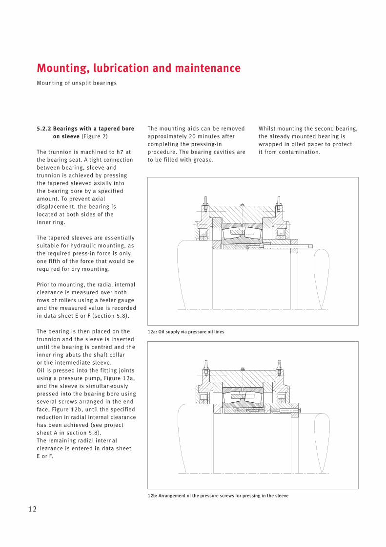
5.2.2 Bearings with a tapered boreon sleeve (Figure 2)
The trunnion is machined to h7 atthe bearing seat. A tight connectionbetween bearing, sleeve and trunnion is achieved by pressingthe tapered sleeved axially into the bearing bore by a specifiedamount. To prevent axial displacement, the bearing is located at both sides of the inner ring.
The tapered sleeves are essentiallysuitable for hydraulic mounting, asthe required press-in force is onlyone fifth of the force that would berequired for dry mounting.
Prior to mounting, the radial internalclearance is measured over bothrows of rollers using a feeler gaugeand the measured value is recordedin data sheet E or F (section 5.8).
The bearing is then placed on thetrunnion and the sleeve is inserteduntil the bearing is centred and theinner ring abuts the shaft collar or the intermediate sleeve. Oil is pressed into the fitting jointsusing a pressure pump, Figure 12a,and the sleeve is simultaneouslypressed into the bearing bore usingseveral screws arranged in the endface, Figure 12b, until the specifiedreduction in radial internal clearancehas been achieved (see projectsheet A in section 5.8). The re maining radial internal clearance is entered in data sheet E or F.
The mounting aids can be removedapproximately 20 minutes aftercompleting the pressing-in procedure. The bearing cavities areto be filled with grease.
Mounting, lubrication and maintenanceMounting of unsplit bearings
12
Whilst mounting the second bearing,the already mounted bearing iswrapped in oiled paper to protect it from contamination.
12b: Arrangement of the pressure screws for pressing in the sleeve
12a: Oil supply via pressure oil lines
5.3 Mounting of split bearings
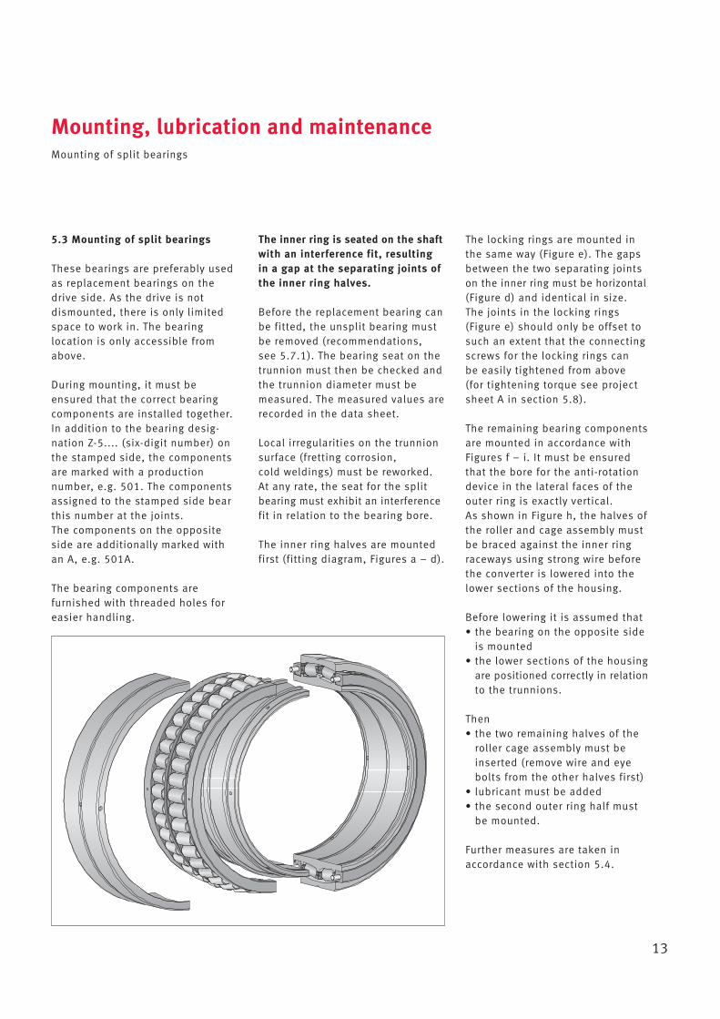
These bearings are preferably usedas replacement bearings on thedrive side. As the drive is not dismounted, there is only limitedspace to work in. The bearing location is only accessible fromabove.
During mounting, it must beensured that the correct bearing components are installed together. In addition to the bearing desig -nation Z-5.... (six-digit number) onthe stamped side, the componentsare marked with a production number, e.g. 501. The components assigned to the stamped side bearthis number at the joints. The components on the oppositeside are additionally marked withan A, e.g. 501A.
The bearing components are furnished with threaded holes foreasier handling.
The inner ring is seated on the shaftwith an interference fit, resultingin a gap at the separating joints ofthe inner ring halves.
Before the replacement bearing canbe fitted, the unsplit bearing mustbe removed (recommendations, see 5.7.1). The bearing seat on thetrunnion must then be checked andthe trunnion diameter must bemeasured. The measured values arerecorded in the data sheet.
Local irregularities on the trunnionsurface (fretting corrosion, cold weldings) must be re worked.At any rate, the seat for the splitbearing must exhibit an interferencefit in relation to the bearing bore.
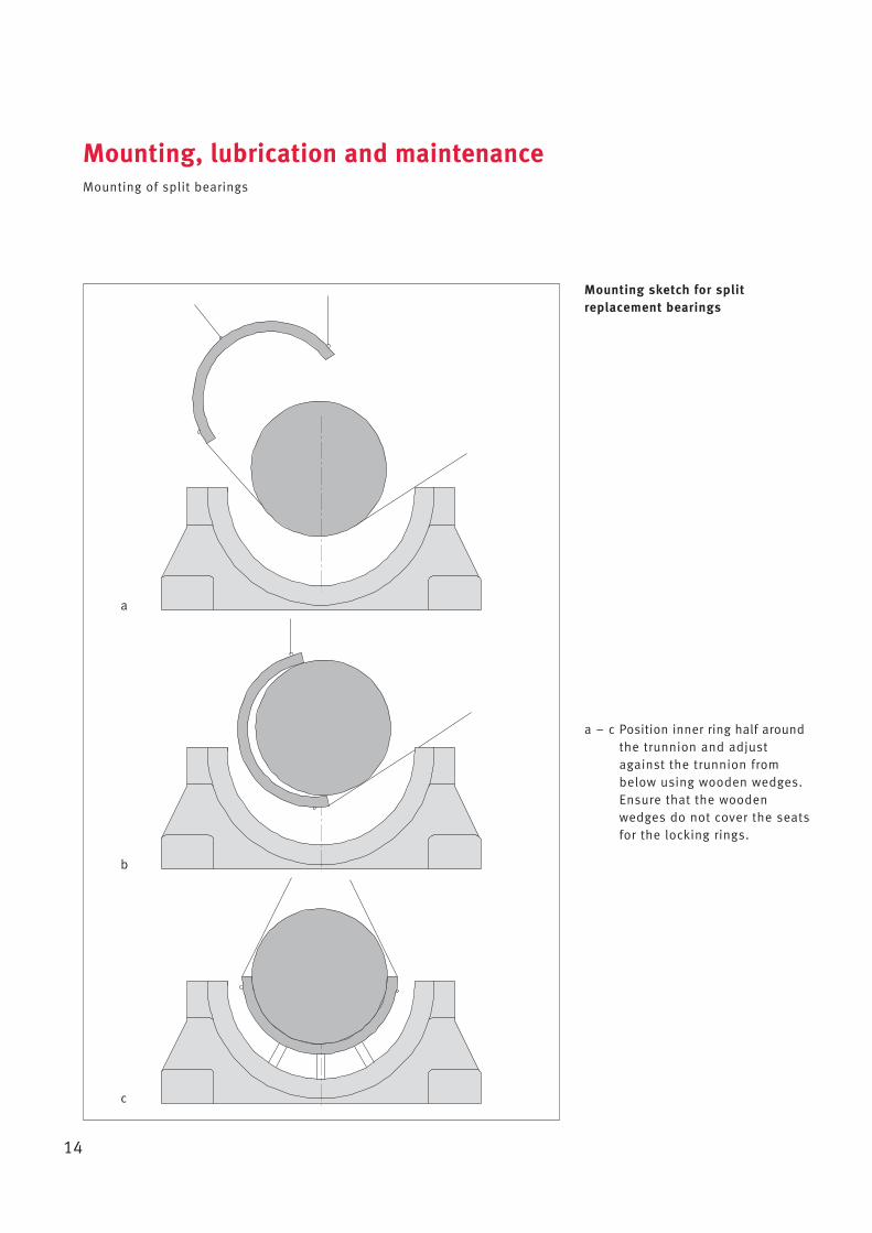
The inner ring halves are mountedfirst (fitting diagram, Figures a – d).
Mounting, lubrication and maintenanceMounting of split bearings
13
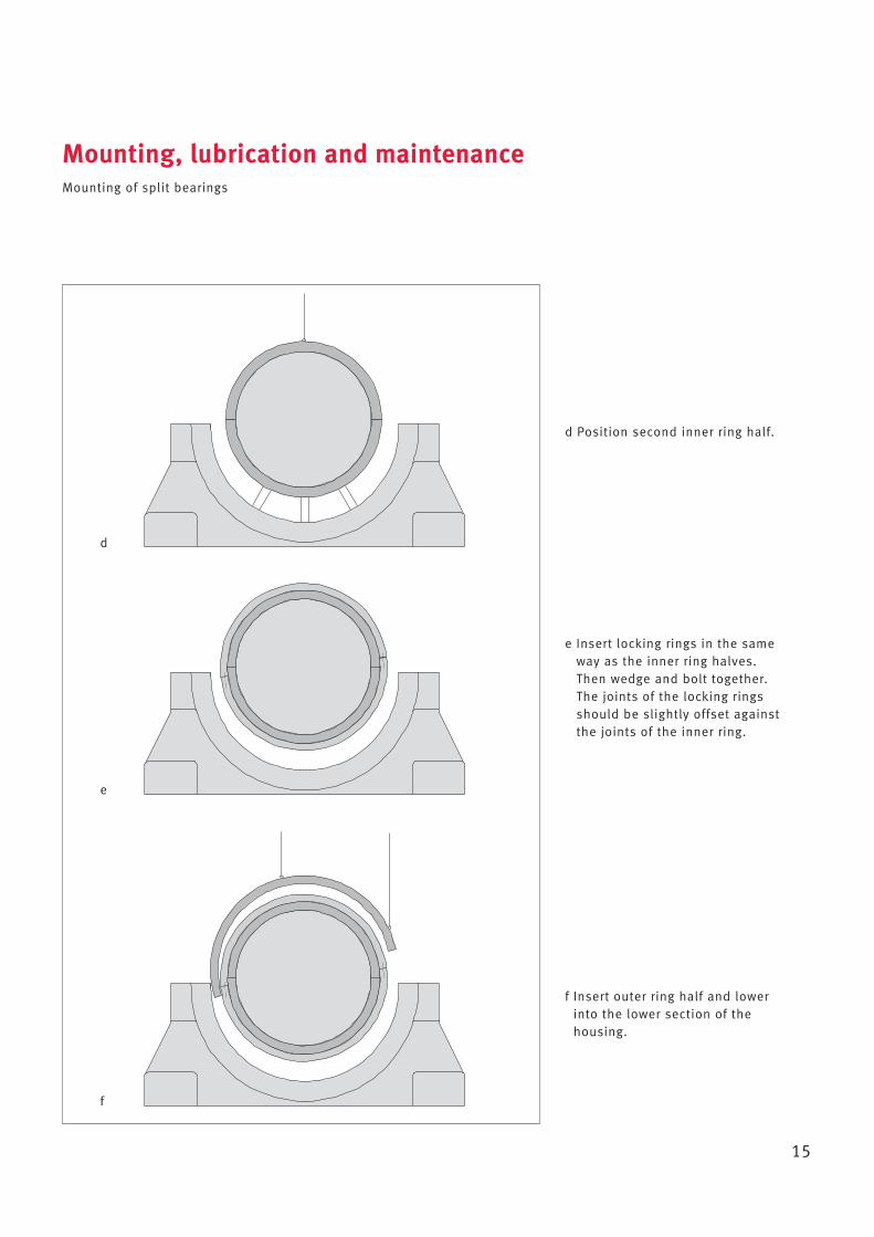
The locking rings are mounted inthe same way (Figure e). The gapsbetween the two separating jointson the inner ring must be horizontal(Figure d) and identical in size. The joints in the locking rings (Figure e) should only be offset tosuch an extent that the connectingscrews for the locking rings can be easily tightened from above (for tightening torque see projectsheet A in section 5.8).
The remaining bearing componentsare mounted in accordance withFigures f – i. It must be ensuredthat the bore for the anti-rotationdevice in the lateral faces of theouter ring is exactly vertical. As shown in Figure h, the halves ofthe roller and cage assembly mustbe braced against the inner ringraceways using strong wire beforethe converter is lowered into thelower sections of the housing.
Before lowering it is assumed that• the bearing on the opposite side
is mounted• the lower sections of the housing
are positioned correctly in relationto the trunnions.
Then• the two remaining halves of the
roller cage assembly must beinserted (remove wire and eyebolts from the other halves first)
• lubricant must be added• the second outer ring half must
be mounted.
Further measures are taken inaccordance with section 5.4.
Mounting, lubrication and maintenanceMounting of split bearings
14
Mounting sketch for split replacement bearings
a – c Position inner ring half aroundthe trunnion and adjustagainst the trunnion frombelow using wooden wedges.Ensure that the woodenwedges do not cover the seatsfor the locking rings.
c
b
a
Mounting, lubrication and maintenanceMounting of split bearings
15
d Position second inner ring half.
e Insert locking rings in the sameway as the inner ring halves. Then wedge and bolt together.The joints of the locking ringsshould be slightly offset againstthe joints of the inner ring.
f Insert outer ring half and lowerinto the lower section of thehousing.
d
e
f
Mounting, lubrication and maintenanceMounting of split bearings
16
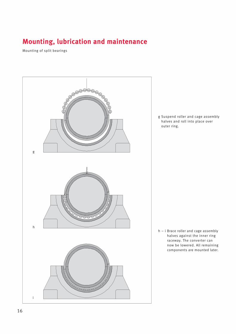
g Suspend roller and cage assemblyhalves and roll into place overouter ring.
h – i Brace roller and cage assemblyhalves against the inner ringraceway. The converter cannow be lowered. All remainingcomponents are mounted later.
g
h
i
5.4 Measures to be taken after mounting
Once both bearings are fitted, thefollowing measures must be taken:
• Check position of the lower sections of the housing in relation to the trunnion and correct if necess ary (static angularmisalignment, see 5.4.1)
• Check position of non-locatingbearing housing in relation to thetrunnion and correct if necessary(displacement possible?)
• Lower converter• Measure internal clearance of
unsplit bearings
• Position the upper section of thehousing
• Insert lubricant (fill approx. 60%of the cavities to the left andright of the bearing)
• Screw lateral cover on• Correct dynamic angular
misalignment in accordance with5.4.2 (vertical error compensatedand housing not rotated in relation to trunnion, see 5.4.1)and enter values in data sheet(section 5.8)
• Determine axial elongation inoperation (1st campaign) andenter value in the data sheet(section 5.8) (displacement fornon-locating bearings, see 5.4.3).
Mounting, lubrication and maintenanceMeasures to be taken after mounting
17
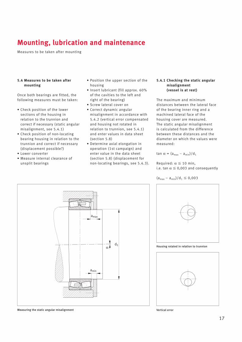
5.4.1 Checking the static angularmisalignment (vessel is at rest)
The maximum and minimum distances between the lateral faceof the bearing inner ring and amachined lateral face of the housing cover are measured. The static angular misalignment is calculated from the differencebetween these distances and thediameter on which the values weremeasured:
tan α = (amax – amin)/d1
Required: α � 10 min, i.e. tan α � 0,003 and consequently
(amax – amin)/d1 � 0,003
Measuring the static angular misalignment
Housing rotated in relation to trunnion
Vertical error
amax
amin
d1α
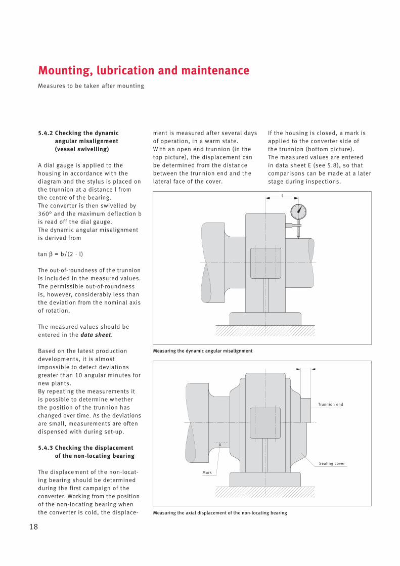
5.4.2 Checking the dynamic angular misalignment (vessel swivelling)
A dial gauge is applied to the housing in accordance with the diagram and the stylus is placed onthe trunnion at a distance l fromthe centre of the bearing. The converter is then swivelled by360° and the maximum de flection bis read off the dial gauge. The dynamic angular misalignmentis derived from
tan β = b/(2 · l)
The out-of-roundness of the trunnionis included in the measured values.The permissible out-of-roundnessis, however, considerably less thanthe deviation from the nominal axisof rotation.
The measured values should beentered in the data sheet.
Based on the latest productiondevelopments, it is almostimpossible to detect deviationsgreater than 10 angular minutes fornew plants. By repeating the measurements itis possible to determine whetherthe position of the trunnion haschanged over time. As the deviationsare small, measurements are oftendispensed with during set-up.
5.4.3 Checking the displacement of the non-locating bearing
The displacement of the non-locat-ing bearing should be determinedduring the first campaign of theconverter. Working from the positionof the non-locating bearing whenthe converter is cold, the displace-
ment is measured after several daysof operation, in a warm state. With an open end trunnion (in thetop picture), the displacement canbe determined from the distancebetween the trunnion end and thelateral face of the cover.
Mounting, lubrication and maintenanceMeasures to be taken after mounting
18
If the housing is closed, a mark isapplied to the converter side of the trunnion (bottom picture). The measured values are entered in data sheet E (see 5.8), so that comparisons can be made at a laterstage during inspections.
Measuring the dynamic angular misalignment
Measuring the axial displacement of the non-locating bearing
x
l
Trunnion end
Sealing cover
Mark
5.5 Lubrication
FAG spherical roller bearings forconverters have a lubricatinggroove and lubricating holes in the middle of the outer ring. During relubrication, lubricant isthen fed directly into the bearings.
Lithium soap greases which containeffective EP and anti-corrosionadditives and, where possible,an MoS2 additive, should be used.
A high base oil viscosity combinedwith a consistency that is not toosoft (NLGI class 2) ensures a goodlubricating condition.
Where possible, relubrication shouldbe carried out using the samegrease as for initial lubrication(see project sheet A in section 5.8).
The bearing lubricant should alsobe used to relubricate the seal, if grease chambers are provided.
The grease quantity for initial lubrication and relubrication and thelubrication intervals can be found inproject sheet A in section 5.8.
5.6 Maintenance
Maintenance of the converter bearing arrangements follows thepattern below:
a ... a b a ... a c a ... a b a etc.
a Activities following initial start-upand during operation, see 5.6.1
b Minor inspection after 1 – 1½ years
c Major inspection after 2 – 3 years
5.6.1 Following initial start-up/between inspections:
1 Measure displacement of non-locating bearing after first“campaign”
2 Relubricate seal after each “campaign” (depending on plant)
3 Lubricate displacement sleeve(non-locating bearing side) aftereach “campaign”
4 Lubricate bearings every 2 to 3 months
5.6.2 Minor inspection after 1 – 1½ years:
1 Remove lateral covers and spentlubricant
2 Check lubricant for contaminantson the spot
3 Check seals, replace if necessary
4 Replenish lubricant
5.6.3 Major inspection after 2 – 3 years:
1 Remove lateral covers and uppersection of the housing andremove spent lubricant
2 Take lubricant samples at differentdistances from the bearing andanalyse them
3 Remove remaining lubricant
4 Determine possible axial displacement of the non-locatingbearing (inwards and outwards),
Mounting, lubrication and maintenanceLubrication · Maintenance
19
compare with the values recordedduring initial assembly and enterin the data sheet
5 Measure radial internal clearanceand enter value in the datasheet (old bearing position)
6 Lift converter until the bearingouter rings are exposed
7 Check surfaces of raceways androlling elements (record condition in data sheet)
8 Mark four arcs, each at 90°, on the outer rings of the unsplitbearings
9 Rotate outer rings and roller and cage assemblies by 180°(then 90° and subsequently180°) and enter the old and new position of the outer ringsin the data sheet
10 Rotate outer ring halves androller and cage assembly halvesof split bearings by 180°
11 Lubricate displacement sleeve
12 Lower converter in this position
13 Measure radial internal clearanceand enter value in the “new bearing position” column
14 Fill bearing and seal with freshlubricant
15 If necessary, use new seals
16 Measure angular misalignment,compare with the values recorded when the converterwas started up and enter in thedata sheet.
5.7 Dismounting
In principle, the procedure describedfor mounting should be followed inreverse.
5.7.1 Bearings with a cylindrical bore
Bearings with a cylindrical bore,which are seated securely on thetrunnion, cannot be dismounted by conventional means. Suitable methods include, forexample, hydraulic dismountingusing additional auxiliary extractiontools. However, this requires holesand ring grooves in the trunnionsfor pressing in the pressure oil. The design featuring a cylindricalseat is intended for installation of asplit replacement bearing (locating bearing on the drive side).As the gearbox is not dismounted,the hydraulic method cannot beused for locating bearings. Due to the considerable amount of work involved, this method is
also unsuitable for the non-locatingbearing side.As a rule, converter bearings with acylindrical bore are destroyed duringdismounting as fatigue has renderedthem unusable. Outer rings andcages are cut up with a cuttingtorch. However, it is essential thatattempts are made to split theinner ring. Should it be necessaryto split the inner ring using the cutting torch, tangential cuts arerequired to ensure that the trunnionis not damaged. Once the outer ring and the two cages have been cut and dismounted, a welding torch isused to heat the inner ring thoroughly (approx. +300 C°) in succession at two opposite pointsover the entire width of the ring.This is then quenched with a jet ofcold water. It is important that asignificant temperature differenceis achieved between the surfaceand the core of the material withthe jet of water, as the resulting tensile stresses will cause the ringto crack.
Mounting, lubrication and maintenanceDismounting · Maintenance forms
20
Due to the risk of injury, the splitting area must be covered. Caution: The ring parts are undersignificant stress and may explode.For the purposes of disposal, storethe ring parts in a secure, coveredcrate.
5.7.2 Bearings with a tapered bore on a hydraulic sleeve
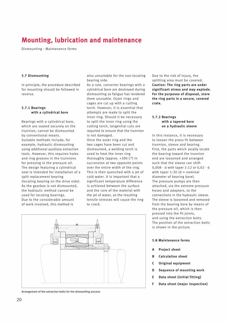
In this instance, it is necessary to loosen the press fit betweentrunnion, sleeve and bearing. First, the parts which axially locatethe bearing toward the trunnionend are loosened and arrangedsuch that the sleeve can shift 0,008 · d with taper 1:12 or 0,02 · dwith taper 1:30 (d = nominal diameter of bearing bore). The pressure pumps are thenattached, via the extreme-pressurehoses and adapters, to the connections in the hydraulic sleeve.The sleeve is loosened and removedfrom the bearing bore by means ofthe pressure oil, which is thenpressed into the fit joints, and using the extraction bolts. The position of the extraction boltsis shown in the picture.
5.8 Maintenance forms
A Project sheet
B Calculation sheet
C Original equipment
D Sequence of mounting work
E Data sheet (initial fitting)
F Data sheet (major inspection)
Arrangement of the extraction bolts for the dismantling process
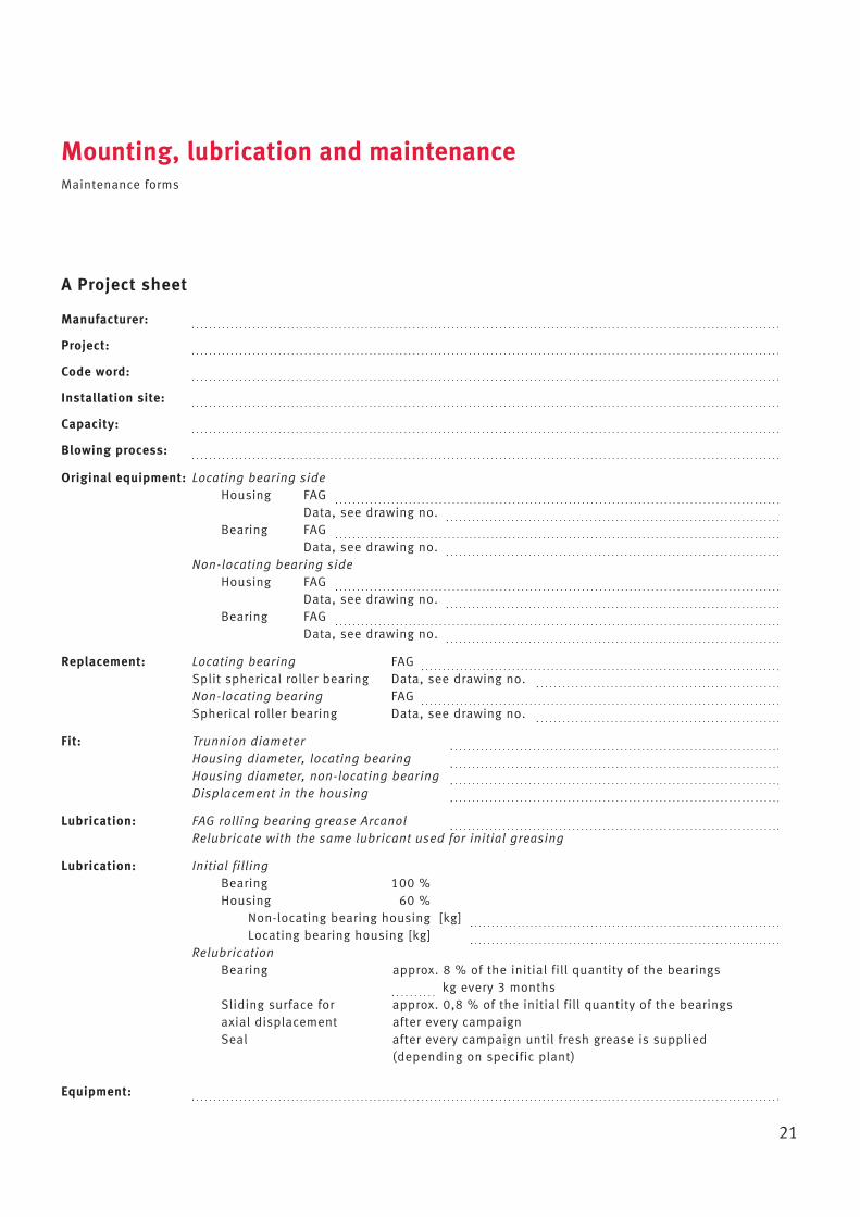
A Project sheet
Manufacturer:
Project:
Code word:
Installation site:
Capacity:
Blowing process:
Original equipment: Locating bearing sideHousing FAG
Data, see drawing no. Bearing FAG
Data, see drawing no. Non-locating bearing side
Housing FAG Data, see drawing no.
Bearing FAG Data, see drawing no.
Replacement: Locating bearing FAG Split spherical roller bearing Data, see drawing no. Non-locating bearing FAG Spherical roller bearing Data, see drawing no.
Fit: Trunnion diameterHousing diameter, locating bearingHousing diameter, non-locating bearingDisplacement in the housing
Lubrication: FAG rolling bearing grease ArcanolRelubricate with the same lubricant used for initial greasing
Lubrication: Initial fillingBearing 100 %Housing 60 %
Non-locating bearing housing [kg]Locating bearing housing [kg]
RelubricationBearing approx. 8 % of the initial fill quantity of the bearings
kg every 3 monthsSliding surface for approx. 0,8 % of the initial fill quantity of the bearings axial displacement after every campaignSeal after every campaign until fresh grease is supplied
(depending on specific plant)
Equipment:
Mounting, lubrication and maintenanceMaintenance forms
21
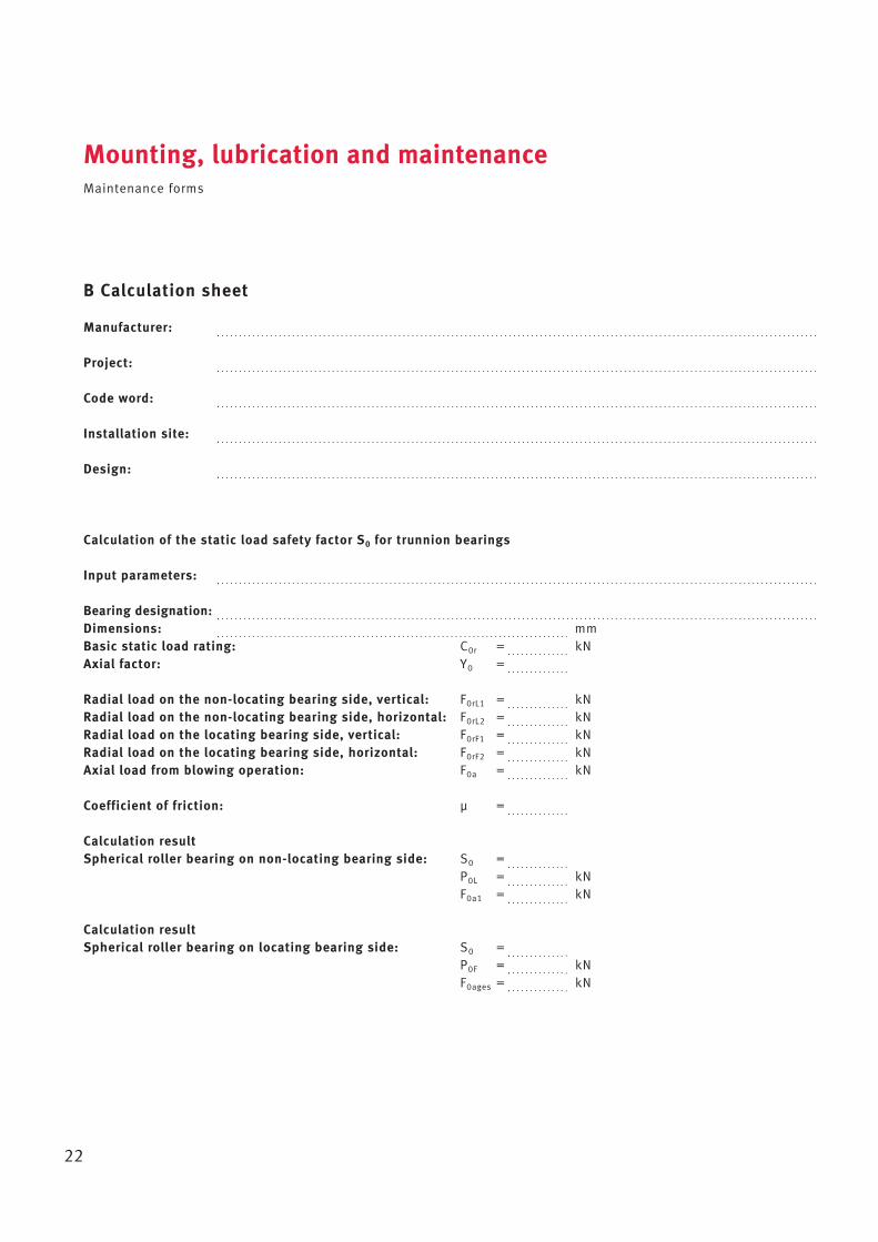
B Calculation sheet
Manufacturer:
Project:
Code word:
Installation site:
Design:
Calculation of the static load safety factor S0 for trunnion bearings
Input parameters:
Bearing designation:Dimensions: mmBasic static load rating: C0r = kNAxial factor: Y0 =
Radial load on the non-locating bearing side, vertical: F0rL1 = kNRadial load on the non-locating bearing side, horizontal: F0rL2 = kNRadial load on the locating bearing side, vertical: F0rF1 = kNRadial load on the locating bearing side, horizontal: F0rF2 = kNAxial load from blowing operation: F0a = kN
Coefficient of friction: μ =
Calculation resultSpherical roller bearing on non-locating bearing side: S0 =
P0L = kNF0a1 = kN
Calculation resultSpherical roller bearing on locating bearing side: S0 =
P0F = kNF0ages = kN
Mounting, lubrication and maintenanceMaintenance forms
22
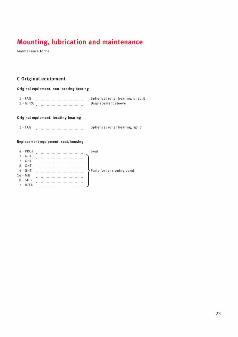
C Original equipment
Original equipment, non-locating bearing
1 - FAG Spherical roller bearing, unsplit1 - GHRG. Displacement sleeve
Original equipment, locating bearing
1 - FAG Spherical roller bearing, split
Replacement equipment, seal/housing
4 - PROF. Seal2 - GHT.2 - GHT.8 - GHT.4 - GHT. Parts for tensioning band
16 - MU8 - SHB2 - DFED
Mounting, lubrication and maintenanceMaintenance forms
23
�
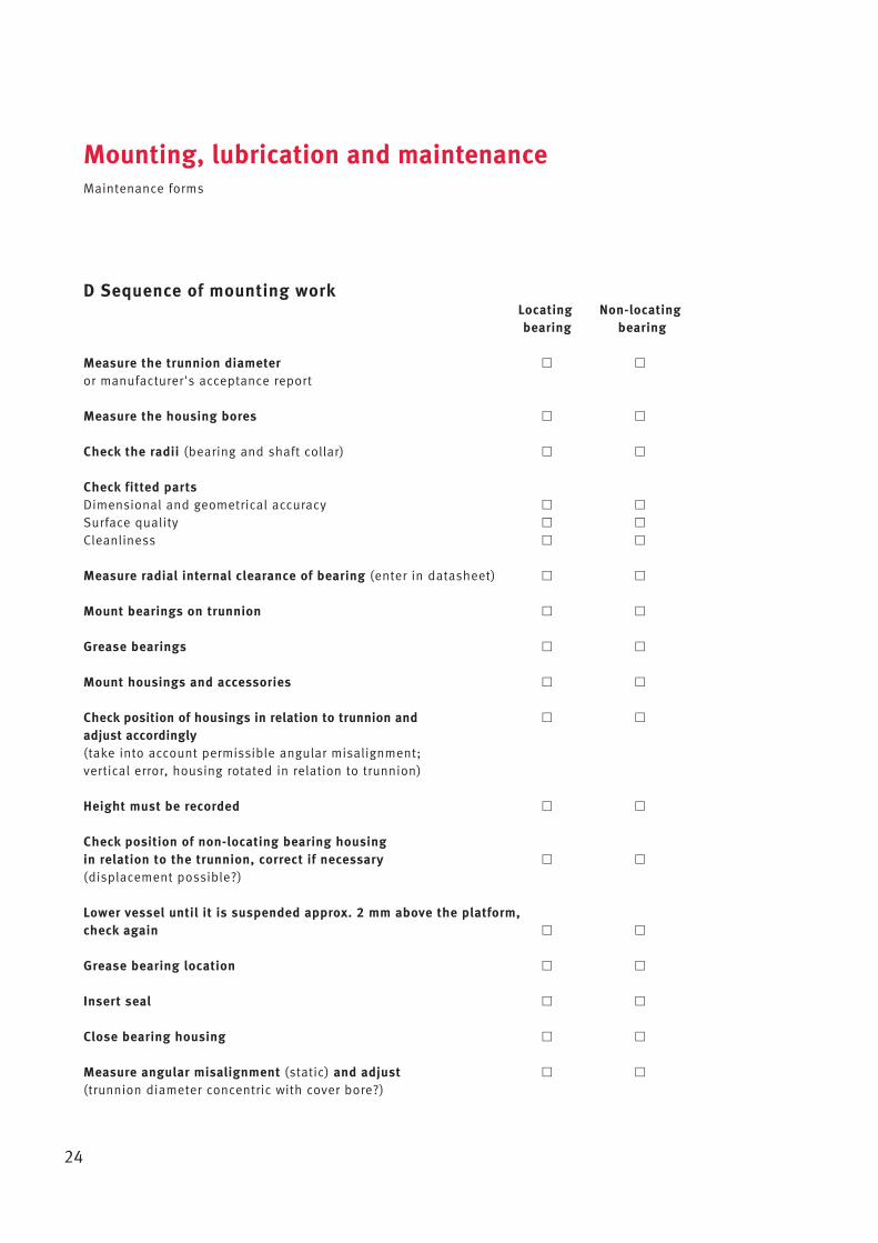
D Sequence of mounting workLocating Non-locatingbearing bearing
Measure the trunnion diameter � �
or manufacturer's acceptance report
Measure the housing bores � �
Check the radii (bearing and shaft collar) � �
Check fitted partsDimensional and geometrical accuracy � �
Surface quality � �
Cleanliness � �
Measure radial internal clearance of bearing (enter in datasheet) � �
Mount bearings on trunnion � �
Grease bearings � �
Mount housings and accessories � �
Check position of housings in relation to trunnion and � �
adjust accordingly(take into account permissible angular misalignment; vertical error, housing rotated in relation to trunnion)
Height must be recorded � �
Check position of non-locating bearing housing in relation to the trunnion, correct if necessary � �
(displacement possible?)
Lower vessel until it is suspended approx. 2 mm above the platform, check again � �
Grease bearing location � �
Insert seal � �
Close bearing housing � �
Measure angular misalignment (static) and adjust � �
(trunnion diameter concentric with cover bore?)
Mounting, lubrication and maintenanceMaintenance forms
24
E Data sheet (initial fitting)
Bearings Locating bearingNon-locating bearing
Locating bearing Non-locating bearing
Radial internal clearance before fitting [mm]
Actual dimension of the trunnion [mm]
Installed radial internal clearance*1 [mm]
Actual dimension of the housing [mm]
Angular misalignment resulting from housing being rotated in relation to trunnionAngular misalignment resulting from vertical errorTotal static angular misalignment
Axial displacement capacity of the non-locating bearinginwards [mm]outwards [mm]
Grease used
Comments:
*1 calculated value
Mounting, lubrication and maintenanceMaintenance forms
25
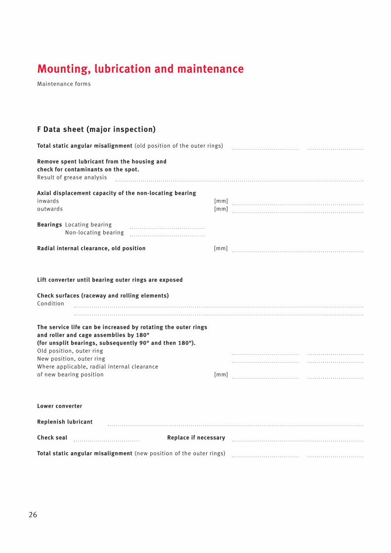
F Data sheet (major inspection)
Total static angular misalignment (old position of the outer rings)
Remove spent lubricant from the housing and check for contaminants on the spot. Result of grease analysis
Axial displacement capacity of the non-locating bearinginwards [mm]outwards [mm]
Bearings Locating bearingNon-locating bearing
Radial internal clearance, old position [mm]
Lift converter until bearing outer rings are exposed
Check surfaces (raceway and rolling elements)Condition
The service life can be increased by rotating the outer rings and roller and cage assemblies by 180° (for unsplit bearings, subsequently 90° and then 180°).Old position, outer ringNew position, outer ringWhere applicable, radial internal clearance of new bearing position [mm]
Lower converter
Replenish lubricant
Check seal Replace if necessary
Total static angular misalignment (new position of the outer rings)
Mounting, lubrication and maintenanceMaintenance forms
26
Dimension tables for rolling bearings and housings forconverters
27
6.1 Spherical roller bearings 28
6.2 Split spherical roller bearings 32
6.3 Housing KPG 36
6.4 Housing KPGZ 40
Dd
B
da Da da
r
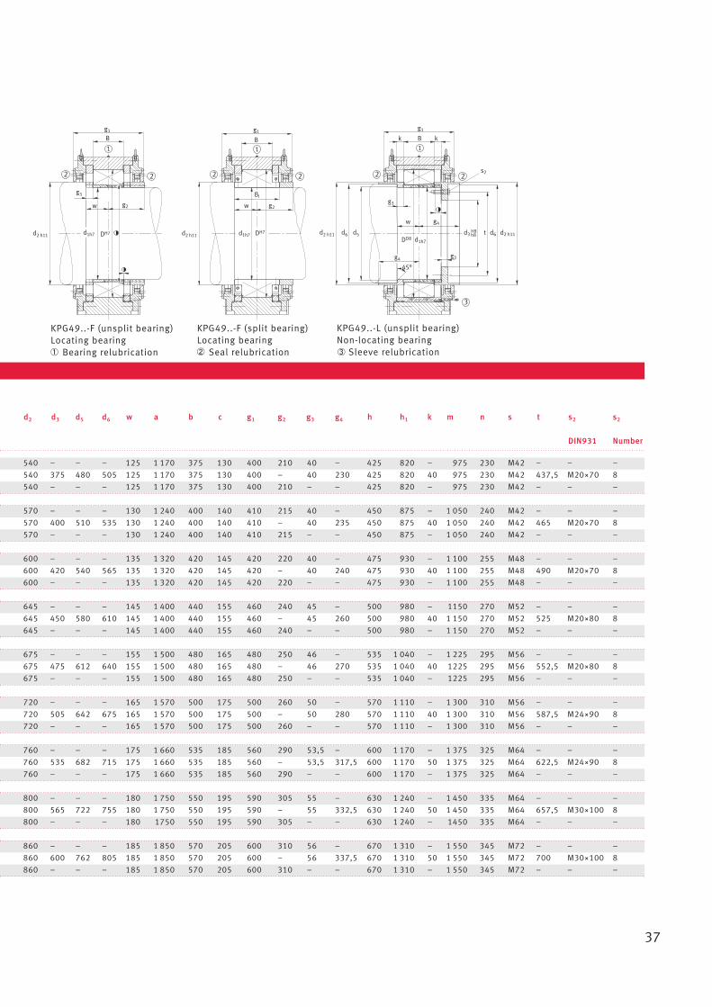
r
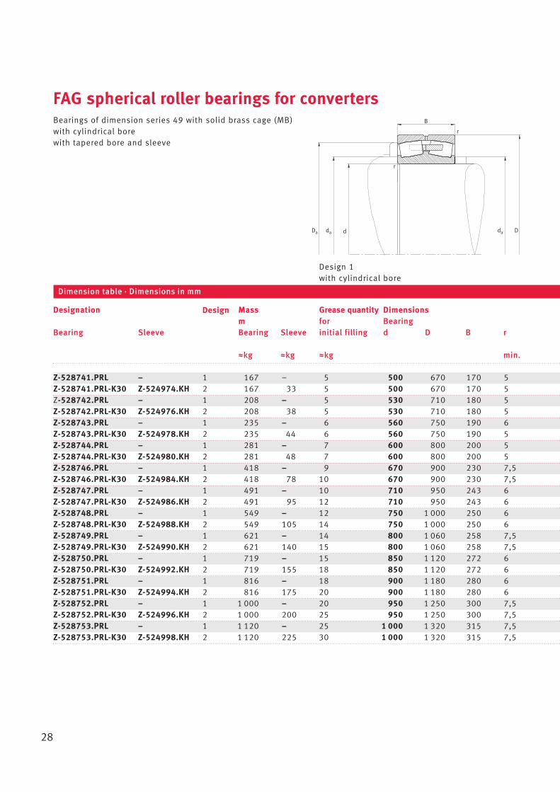
FAG spherical roller bearings for convertersBearings of dimension series 49 with solid brass cage (MB)with cylindrical borewith tapered bore and sleeve
28
Z-528741.PRL – 1 167 – 5 500 670 170 5Z-528741.PRL-K30 Z-524974.KH 2 167 33 5 500 670 170 5Z-528742.PRL – 1 208 – 5 530 710 180 5Z-528742.PRL-K30 Z-524976.KH 2 208 38 5 530 710 180 5Z-528743.PRL – 1 235 – 6 560 750 190 6Z-528743.PRL-K30 Z-524978.KH 2 235 44 6 560 750 190 5Z-528744.PRL – 1 281 – 7 600 800 200 5Z-528744.PRL-K30 Z-524980.KH 2 281 48 7 600 800 200 5Z-528746.PRL – 1 418 – 9 670 900 230 7,5Z-528746.PRL-K30 Z-524984.KH 2 418 78 10 670 900 230 7,5Z-528747.PRL – 1 491 – 10 710 950 243 6Z-528747.PRL-K30 Z-524986.KH 2 491 95 12 710 950 243 6Z-528748.PRL – 1 549 – 12 750 1 000 250 6Z-528748.PRL-K30 Z-524988.KH 2 549 105 14 750 1 000 250 6Z-528749.PRL – 1 621 – 14 800 1 060 258 7,5Z-528749.PRL-K30 Z-524990.KH 2 621 140 15 800 1 060 258 7,5Z-528750.PRL – 1 719 – 15 850 1 120 272 6Z-528750.PRL-K30 Z-524992.KH 2 719 155 18 850 1 120 272 6Z-528751.PRL – 1 816 – 18 900 1 180 280 6Z-528751.PRL-K30 Z-524994.KH 2 816 175 20 900 1 180 280 6Z-528752.PRL – 1 1 000 – 20 950 1 250 300 7,5Z-528752.PRL-K30 Z-524996.KH 2 1 000 200 25 950 1 250 300 7,5Z-528753.PRL – 1 1 120 – 25 1 000 1 320 315 7,5Z-528753.PRL-K30 Z-524998.KH 2 1 120 225 30 1 000 1 320 315 7,5
Designation Mass Grease quantity Dimensionsm for Bearing
Bearing Sleeve Bearing Sleeve initial filling d D B r
Wkg Wkg Wkg min.
Dimension table · Dimensions in mm
Design 1with cylindrical bore
Design
29
l
Ddb
d
B
d1H
a
da Da da
R0
r
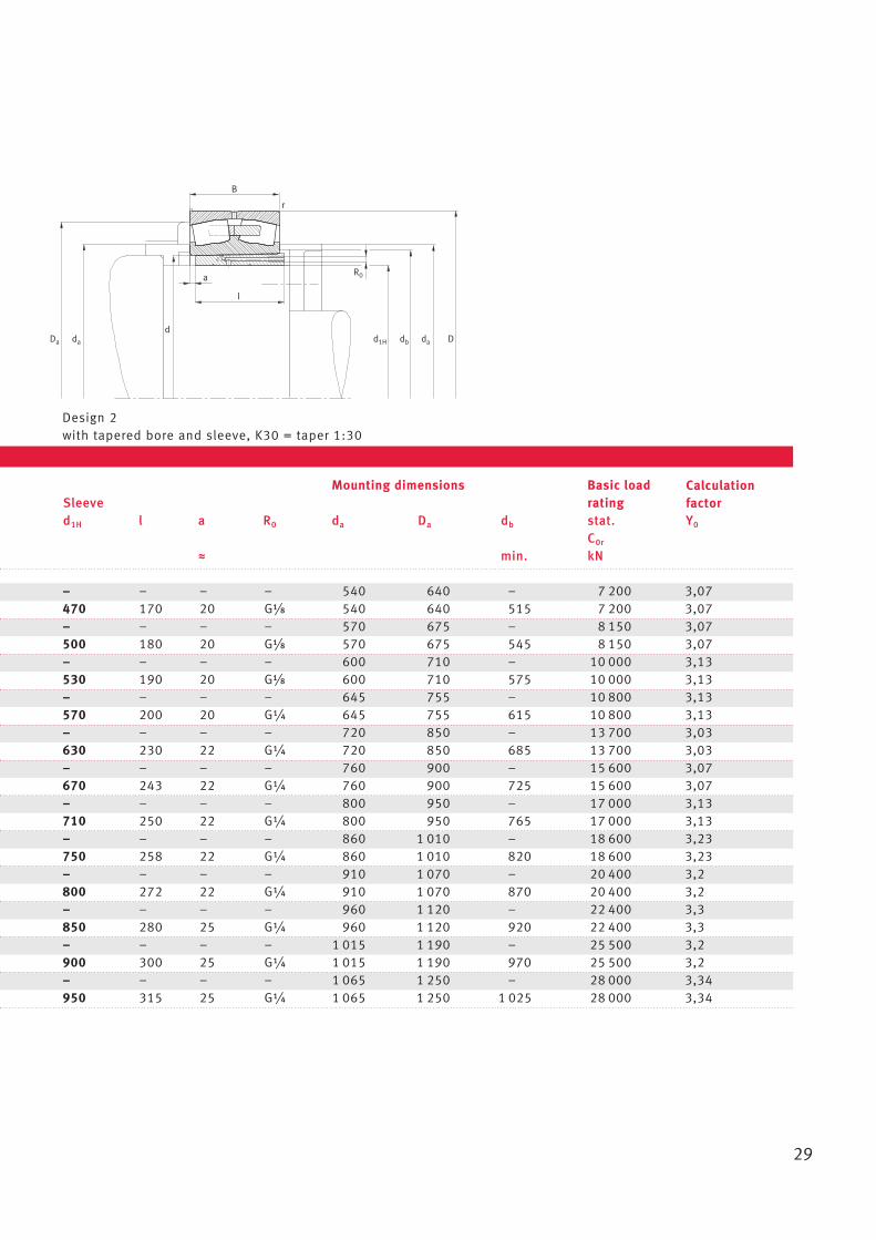
Mounting dimensions Basic load Sleeve ratingd1H l a R0 da Da db stat. Y0
C0r
W min. kN
– – – – 540 640 – 7 200 3,07470 170 20 GB/i 540 640 515 7 200 3,07– – – – 570 675 – 8 150 3,07500 180 20 GB/i 570 675 545 8 150 3,07– – – – 600 710 – 10 000 3,13530 190 20 GB/i 600 710 575 10 000 3,13– – – – 645 755 – 10 800 3,13570 200 20 G¼ 645 755 615 10 800 3,13– – – – 720 850 – 13 700 3,03630 230 22 G¼ 720 850 685 13 700 3,03– – – – 760 900 – 15 600 3,07670 243 22 G¼ 760 900 725 15 600 3,07– – – – 800 950 – 17 000 3,13710 250 22 G¼ 800 950 765 17 000 3,13– – – – 860 1 010 – 18 600 3,23750 258 22 G¼ 860 1 010 820 18 600 3,23– – – – 910 1 070 – 20 400 3,2800 272 22 G¼ 910 1 070 870 20 400 3,2– – – – 960 1 120 – 22 400 3,3850 280 25 G¼ 960 1 120 920 22 400 3,3– – – – 1 015 1 190 – 25 500 3,2900 300 25 G¼ 1 015 1 190 970 25 500 3,2– – – – 1 065 1 250 – 28 000 3,34950 315 25 G¼ 1 065 1 250 1 025 28 000 3,34
Design 2with tapered bore and sleeve, K30 = taper 1:30
Calculation factor
30
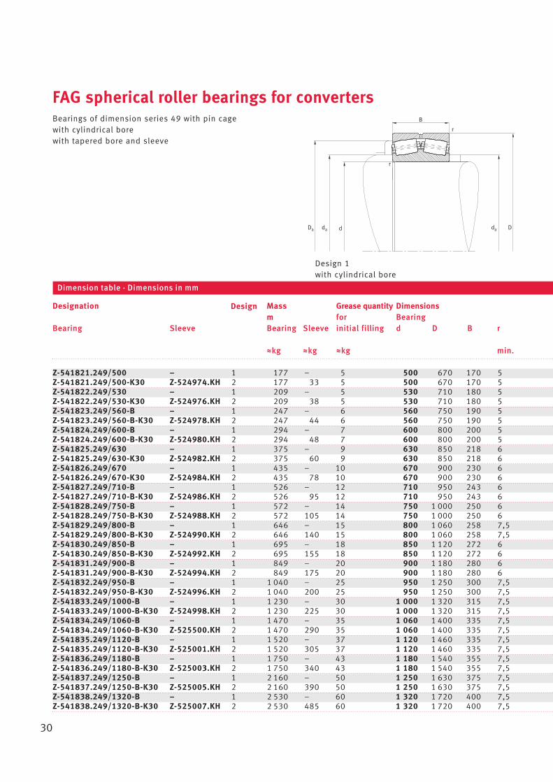
FAG spherical roller bearings for convertersBearings of dimension series 49 with pin cagewith cylindrical borewith tapered bore and sleeve
Designation Mass Grease quantity Dimensionsm for Bearing
Bearing Sleeve Bearing Sleeve initial filling d D B r
Wkg Wkg Wkg min.
Dimension table · Dimensions in mm
Design 1with cylindrical bore
Dd
B
da Da da
r
r
Design
Z-541821.249/500 – 1 177 – 5 500 670 170 5Z-541821.249/500-K30 Z-524974.KH 2 177 33 5 500 670 170 5Z-541822.249/530 – 1 209 – 5 530 710 180 5Z-541822.249/530-K30 Z-524976.KH 2 209 38 5 530 710 180 5Z-541823.249/560-B – 1 247 – 6 560 750 190 5Z-541823.249/560-B-K30 Z-524978.KH 2 247 44 6 560 750 190 5Z-541824.249/600-B – 1 294 – 7 600 800 200 5Z-541824.249/600-B-K30 Z-524980.KH 2 294 48 7 600 800 200 5Z-541825.249/630 – 1 375 – 9 630 850 218 6Z-541825.249/630-K30 Z-524982.KH 2 375 60 9 630 850 218 6Z-541826.249/670 – 1 435 – 10 670 900 230 6Z-541826.249/670-K30 Z-524984.KH 2 435 78 10 670 900 230 6Z-541827.249/710-B – 1 526 – 12 710 950 243 6Z-541827.249/710-B-K30 Z-524986.KH 2 526 95 12 710 950 243 6Z-541828.249/750-B – 1 572 – 14 750 1 000 250 6Z-541828.249/750-B-K30 Z-524988.KH 2 572 105 14 750 1 000 250 6Z-541829.249/800-B – 1 646 – 15 800 1 060 258 7,5Z-541829.249/800-B-K30 Z-524990.KH 2 646 140 15 800 1 060 258 7,5Z-541830.249/850-B – 1 695 – 18 850 1 120 272 6Z-541830.249/850-B-K30 Z-524992.KH 2 695 155 18 850 1 120 272 6Z-541831.249/900-B – 1 849 – 20 900 1 180 280 6Z-541831.249/900-B-K30 Z-524994.KH 2 849 175 20 900 1 180 280 6Z-541832.249/950-B – 1 1 040 – 25 950 1 250 300 7,5Z-541832.249/950-B-K30 Z-524996.KH 2 1 040 200 25 950 1 250 300 7,5Z-541833.249/1000-B – 1 1 230 – 30 1 000 1 320 315 7,5Z-541833.249/1000-B-K30 Z-524998.KH 2 1 230 225 30 1 000 1 320 315 7,5Z-541834.249/1060-B – 1 1 470 – 35 1 060 1 400 335 7,5Z-541834.249/1060-B-K30 Z-525500.KH 2 1 470 290 35 1 060 1 400 335 7,5Z-541835.249/1120-B – 1 1 520 – 37 1 120 1 460 335 7,5Z-541835.249/1120-B-K30 Z-525001.KH 2 1 520 305 37 1 120 1 460 335 7,5Z-541836.249/1180-B – 1 1 750 – 43 1 180 1 540 355 7,5Z-541836.249/1180-B-K30 Z-525003.KH 2 1 750 340 43 1 180 1 540 355 7,5Z-541837.249/1250-B – 1 2 160 – 50 1 250 1 630 375 7,5Z-541837.249/1250-B-K30 Z-525005.KH 2 2 160 390 50 1 250 1 630 375 7,5Z-541838.249/1320-B – 1 2 530 – 60 1 320 1 720 400 7,5Z-541838.249/1320-B-K30 Z-525007.KH 2 2 530 485 60 1 320 1 720 400 7,5
31
l
Ddb
d
B
d1H
a
da Da da
R0
r
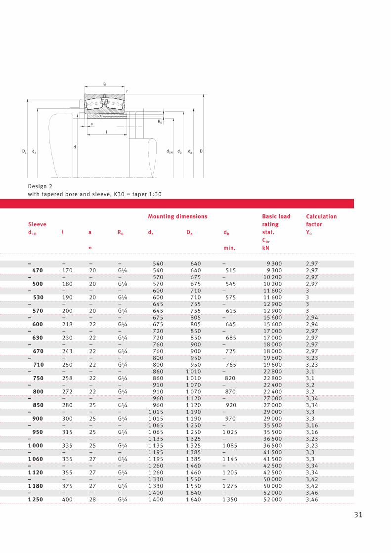
Mounting dimensions Basic load Sleeve ratingd1H l a R0 da Da db stat. Y0
C0r
W min. kN
– – – – 540 640 – 9 300 2,97470 170 20 GB/i 540 640 515 9 300 2,97
– – – – 570 675 – 10 200 2,97500 180 20 GB/i 570 675 545 10 200 2,97
– – – – 600 710 – 11 600 3530 190 20 GB/i 600 710 575 11 600 3
– – – – 645 755 – 12 900 3570 200 20 G¼ 645 755 615 12 900 3
– – – – 675 805 – 15 600 2,94600 218 22 G¼ 675 805 645 15 600 2,94
– – – – 720 850 – 17 000 2,97630 230 22 G¼ 720 850 685 17 000 2,97
– – – – 760 900 – 18 000 2,97670 243 22 G¼ 760 900 725 18 000 2,97
– – – – 800 950 – 19 600 3,23710 250 22 G¼ 800 950 765 19 600 3,23
– – – – 860 1 010 – 22 800 3,1750 258 22 G¼ 860 1 010 820 22 800 3,1
– – – – 910 1 070 – 22 400 3,2800 272 22 G¼ 910 1 070 870 22 400 3,2
– – – – 960 1 120 – 27 000 3,34850 280 25 G¼ 960 1 120 920 27 000 3,34
– – – – 1 015 1 190 – 29 000 3,3900 300 25 G¼ 1 015 1 190 970 29 000 3,3
– – – – 1 065 1 250 – 35 500 3,16950 315 25 G¼ 1 065 1 250 1 025 35 500 3,16
– – – – 1 135 1 325 – 36 500 3,231 000 335 25 G¼ 1 135 1 325 1 085 36 500 3,23– – – – 1 195 1 385 – 41 500 3,31 060 335 27 G¼ 1 195 1 385 1 145 41 500 3,3– – – – 1 260 1 460 – 42 500 3,341 120 355 27 G¼ 1 260 1 460 1 205 42 500 3,34– – – – 1 330 1 550 – 50 000 3,421 180 375 27 G¼ 1 330 1 550 1 275 50 000 3,42– – – – 1 400 1 640 – 52 000 3,461 250 400 28 G¼ 1 400 1 640 1 350 52 000 3,46
Design 2with tapered bore and sleeve, K30 = taper 1:30
Calculation factor
32
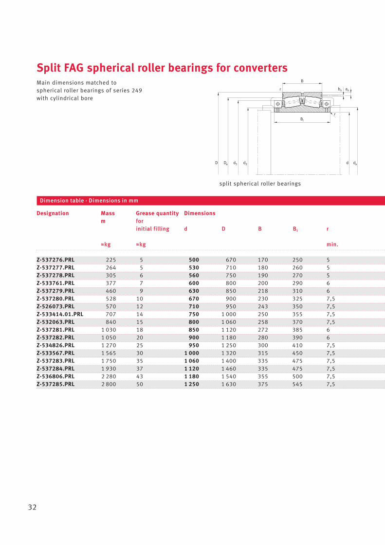
Split FAG spherical roller bearings for convertersMain dimensions matched tospherical roller bearings of series 249with cylindrical bore
Z-537276.PRL 225 5 500 670 170 250 5Z-537277.PRL 264 5 530 710 180 260 5Z-537278.PRL 305 6 560 750 190 270 5Z-533761.PRL 377 7 600 800 200 290 6Z-537279.PRL 460 9 630 850 218 310 6Z-537280.PRL 528 10 670 900 230 325 7,5Z-526073.PRL 570 12 710 950 243 350 7,5Z-533414.01.PRL 707 14 750 1 000 250 355 7,5Z-532063.PRL 840 15 800 1 060 258 370 7,5Z-537281.PRL 1 030 18 850 1 120 272 385 6Z-537282.PRL 1 050 20 900 1 180 280 390 6Z-534826.PRL 1 270 25 950 1 250 300 410 7,5Z-533567.PRL 1 565 30 1 000 1 320 315 450 7,5Z-537283.PRL 1 750 35 1 060 1 400 335 475 7,5Z-537284.PRL 1 930 37 1 120 1 460 335 475 7,5Z-536806.PRL 2 280 43 1 180 1 540 355 500 7,5Z-537285.PRL 2 800 50 1 250 1 630 375 545 7,5
Designation Mass Grease quantity Dimensionsm for
initial filling d D B Bi r
Wkg Wkg min.
Dimension table · Dimensions in mm
split spherical roller bearings
D d3Da
anbn
r
r
dad
B
d2
Bi
33
Bi
DDad
B
da
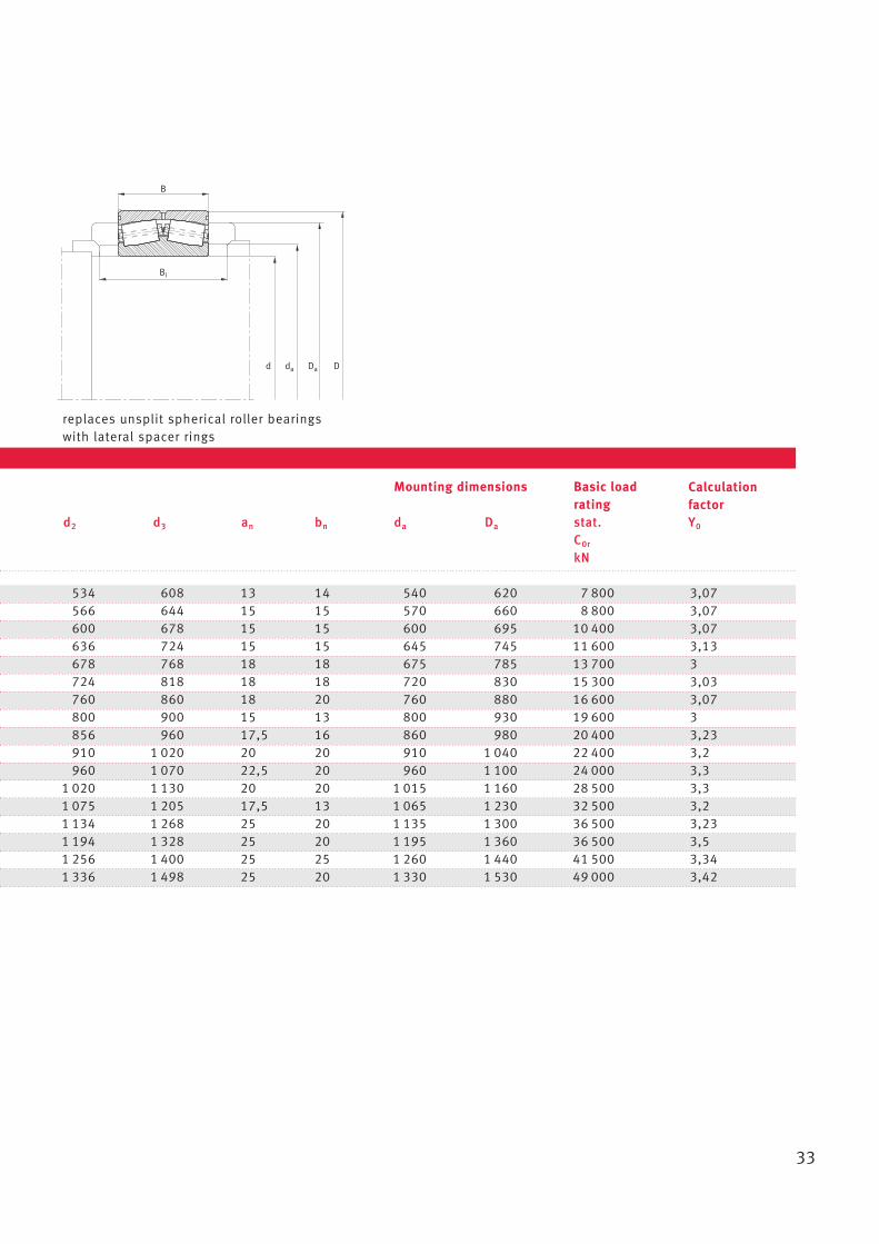
Mounting dimensions Basic load rating
d2 d3 an bn da Da stat. Y0
C0r
kN
534 608 13 14 540 620 7 800 3,07566 644 15 15 570 660 8 800 3,07600 678 15 15 600 695 10 400 3,07636 724 15 15 645 745 11 600 3,13678 768 18 18 675 785 13 700 3724 818 18 18 720 830 15 300 3,03760 860 18 20 760 880 16 600 3,07800 900 15 13 800 930 19 600 3856 960 17,5 16 860 980 20 400 3,23910 1 020 20 20 910 1 040 22 400 3,2960 1 070 22,5 20 960 1 100 24 000 3,3
1 020 1 130 20 20 1 015 1 160 28 500 3,31 075 1 205 17,5 13 1 065 1 230 32 500 3,21 134 1 268 25 20 1 135 1 300 36 500 3,231 194 1 328 25 20 1 195 1 360 36 500 3,51 256 1 400 25 25 1 260 1 440 41 500 3,341 336 1 498 25 20 1 330 1 530 49 000 3,42
replaces unsplit spherical roller bearings with lateral spacer rings
Calculation factor
34
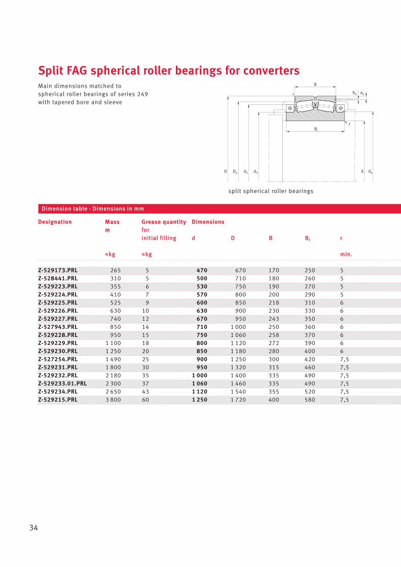
Split FAG spherical roller bearings for convertersMain dimensions matched tospherical roller bearings of series 249with tapered bore and sleeve
Z-529173.PRL 265 5 470 670 170 250 5Z-528441.PRL 310 5 500 710 180 260 5Z-529223.PRL 355 6 530 750 190 270 5Z-529224.PRL 410 7 570 800 200 290 5Z-529225.PRL 525 9 600 850 218 310 6Z-529226.PRL 630 10 630 900 230 330 6Z-529227.PRL 740 12 670 950 243 350 6Z-527943.PRL 850 14 710 1 000 250 360 6Z-529228.PRL 950 15 750 1 060 258 370 6Z-529229.PRL 1 100 18 800 1 120 272 390 6Z-529230.PRL 1 250 20 850 1 180 280 400 6Z-527254.PRL 1 490 25 900 1 250 300 420 7,5Z-529231.PRL 1 800 30 950 1 320 315 460 7,5Z-529232.PRL 2 180 35 1 000 1 400 335 490 7,5Z-529233.01.PRL 2 300 37 1 060 1 460 335 490 7,5Z-529234.PRL 2 650 43 1 120 1 540 355 520 7,5Z-529215.PRL 3 800 60 1 250 1 720 400 580 7,5
Designation Mass Grease quantity Dimensionsm for
initial filling d D B Bi r
Wkg Wkg min.
Dimension table · Dimensions in mm
split spherical roller bearings
Bi
D d 3Da
anbn
r
r
dad
B
d 2
35
B
Bi
DDad da
Mounting dimensions Basic load rating
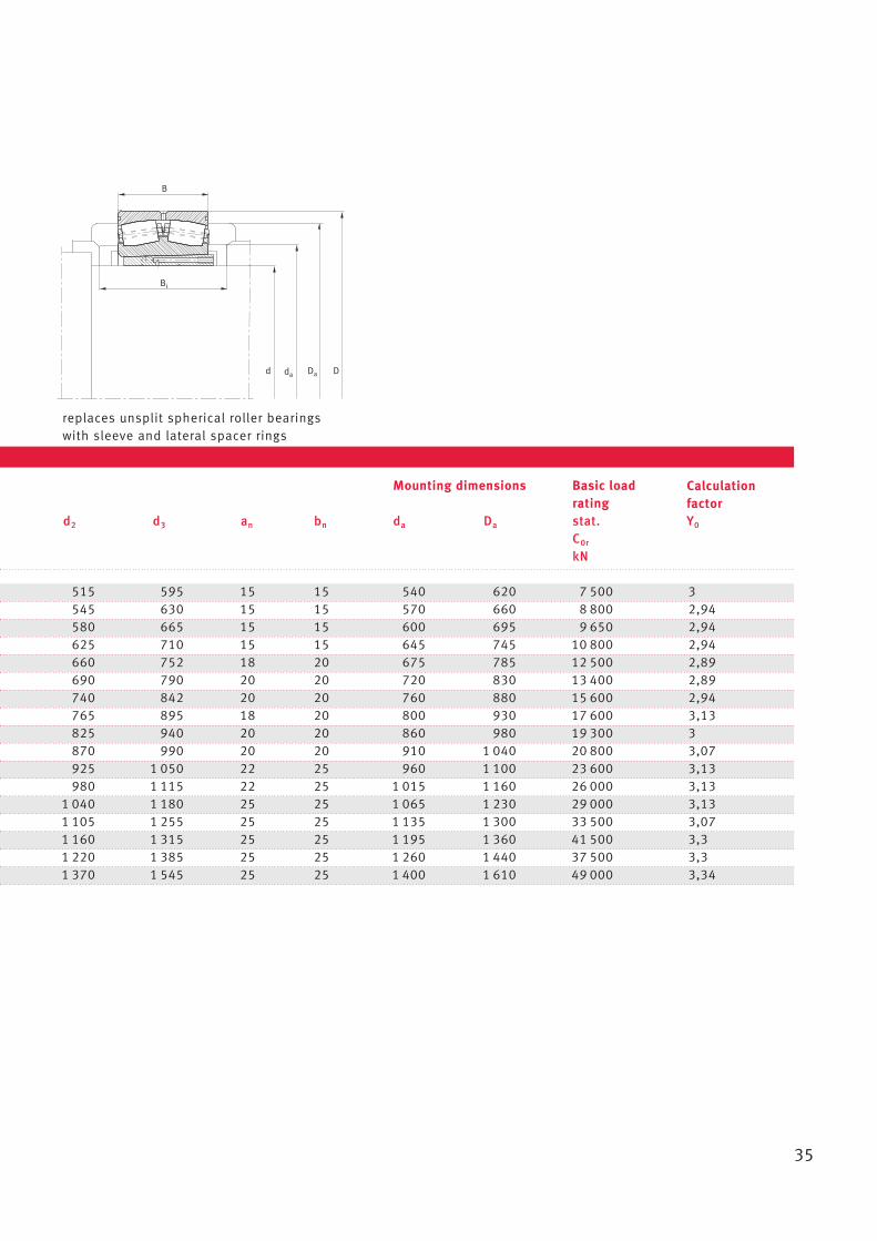
d2 d3 an bn da Da stat. Y0
C0r
kN
515 595 15 15 540 620 7 500 3545 630 15 15 570 660 8 800 2,94580 665 15 15 600 695 9 650 2,94625 710 15 15 645 745 10 800 2,94660 752 18 20 675 785 12 500 2,89690 790 20 20 720 830 13 400 2,89740 842 20 20 760 880 15 600 2,94765 895 18 20 800 930 17 600 3,13825 940 20 20 860 980 19 300 3870 990 20 20 910 1 040 20 800 3,07925 1 050 22 25 960 1 100 23 600 3,13980 1 115 22 25 1 015 1 160 26 000 3,13
1 040 1 180 25 25 1 065 1 230 29 000 3,131 105 1 255 25 25 1 135 1 300 33 500 3,071 160 1 315 25 25 1 195 1 360 41 500 3,31 220 1 385 25 25 1 260 1 440 37 500 3,31 370 1 545 25 25 1 400 1 610 49 000 3,34
replaces unsplit spherical roller bearings with sleeve and lateral spacer rings
Calculation factor
36
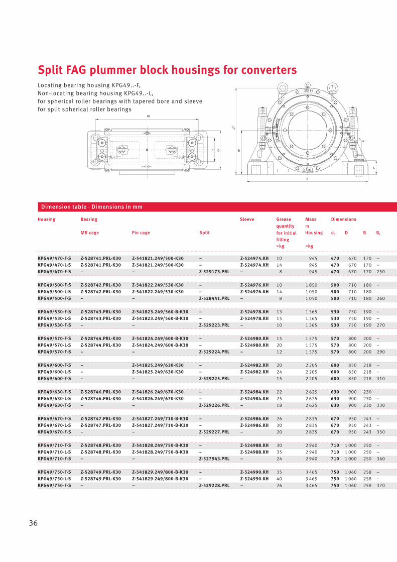
Split FAG plummer block housings for convertersLocating bearing housing KPG49..-F,Non-locating bearing housing KPG49..-L,for spherical roller bearings with tapered bore and sleevefor split spherical roller bearings
KPG49/470-F-S Z-528741.PRL-K30 Z-541821.249/500-K30 – Z-524974.KH 10 945 470 670 170 –
KPG49/470-L-S Z-528741.PRL-K30 Z-541821.249/500-K30 – Z-524974.KH 14 945 470 670 170 –
KPG49/470-F-S – – Z-529173.PRL – 8 945 470 670 170 250
KPG49/500-F-S Z-528742.PRL-K30 Z-541822.249/530-K30 – Z-524976.KH 10 1 050 500 710 180 –
KPG49/500-L-S Z-528742.PRL-K30 Z-541822.249/530-K30 – Z-524976.KH 14 1 050 500 710 180 –
KPG49/500-F-S – – Z-528441.PRL – 8 1 050 500 710 180 260
KPG49/530-F-S Z-528743.PRL-K30 Z-541823.249/560-B-K30 – Z-524978.KH 13 1 365 530 750 190 –
KPG49/530-L-S Z-528743.PRL-K30 Z-541823.249/560-B-K30 – Z-524978.KH 15 1 365 530 750 190 –
KPG49/530-F-S – – Z-529223.PRL – 10 1 365 530 750 190 270
KPG49/570-F-S Z-528744.PRL-K30 Z-541824.249/600-B-K30 – Z-524980.KH 15 1 575 570 800 200 –
KPG49/570-L-S Z-528744.PRL-K30 Z-541824.249/600-B-K30 – Z-524980.KH 20 1 575 570 800 200 –
KPG49/570-F-S – – Z-529224.PRL – 12 1 575 570 800 200 290
KPG49/600-F-S – Z-541825.249/630-K30 – Z-524982.KH 20 2 205 600 850 218 –
KPG49/600-L-S – Z-541825.249/630-K30 – Z-524982.KH 24 2 205 600 850 218 –
KPG49/600-F-S – – Z-529225.PRL – 15 2 205 600 850 218 310
KPG49/630-F-S Z-528746.PRL-K30 Z-541826.249/670-K30 – Z-524984.KH 22 2 625 630 900 230 –
KPG49/630-L-S Z-528746.PRL-K30 Z-541826.249/670-K30 – Z-524984.KH 25 2 625 630 900 230 –
KPG49/630-F-S – – Z-529226.PRL – 18 2 625 630 900 230 330
KPG49/670-F-S Z-528747.PRL-K30 Z-541827.249/710-B-K30 – Z-524986.KH 26 2 835 670 950 243 –
KPG49/670-L-S Z-528747.PRL-K30 Z-541827.249/710-B-K30 – Z-524986.KH 30 2 835 670 950 243 –
KPG49/670-F-S – – Z-529227.PRL – 20 2 835 670 950 243 350
KPG49/710-F-S Z-528748.PRL-K30 Z-541828.249/750-B-K30 – Z-524988.KH 30 2 940 710 1 000 250 –
KPG49/710-L-S Z-528748.PRL-K30 Z-541828.249/750-B-K30 – Z-524988.KH 35 2 940 710 1 000 250 –
KPG49/710-F-S – – Z-527943.PRL – 24 2 940 710 1 000 250 360
KPG49/750-F-S Z-528749.PRL-K30 Z-541829.249/800-B-K30 – Z-524990.KH 35 3 465 750 1 060 258 –
KPG49/750-L-S Z-528749.PRL-K30 Z-541829.249/800-B-K30 – Z-524990.KH 40 3 465 750 1 060 258 –
KPG49/750-F-S – – Z-529228.PRL – 26 3 465 750 1 060 258 370
Housing Bearing Sleeve Grease Mass Dimensionsquantity m
MB cage Pin cage Split Housing d1 D B Bi
Wkg Wkg
Dimension table · Dimensions in mm
a
h1
h
s
c
bn
m
for initial
filling
37
22
1
22
1
22
1
g1
DH7d1h7
B
g3
w g2
3
g1
d2 h11 DH7d1h7
B
w g2
d2 h11
k k
g1
B
g3
DD8 d1h7
d6 d5
w g4
g3
g4
d3H8h8 t d6 d2 h11
45°
s2
d2 h11
Bi
KPG49..-F (unsplit bearing)Locating bearing
Bearing relubrication
540 – – – 125 1 170 375 130 400 210 40 – 425 820 – 975 230 M42 – – –
540 375 480 505 125 1 170 375 130 400 – 40 230 425 820 40 975 230 M42 437,5 M20~70 8
540 – – – 125 1 170 375 130 400 210 – – 425 820 – 975 230 M42 – – –
570 – – – 130 1 240 400 140 410 215 40 – 450 875 – 1 050 240 M42 – – –
570 400 510 535 130 1 240 400 140 410 – 40 235 450 875 40 1 050 240 M42 465 M20~70 8
570 – – – 130 1 240 400 140 410 215 – – 450 875 – 1 050 240 M42 – – –
600 – – – 135 1 320 420 145 420 220 40 – 475 930 – 1 100 255 M48 – – –
600 420 540 565 135 1 320 420 145 420 – 40 240 475 930 40 1 100 255 M48 490 M20~70 8
600 – – – 135 1 320 420 145 420 220 – – 475 930 – 1 100 255 M48 – – –
645 – – – 145 1 400 440 155 460 240 45 – 500 980 – 1150 270 M52 – – –
645 450 580 610 145 1 400 440 155 460 – 45 260 500 980 40 1 150 270 M52 525 M20~80 8
645 – – – 145 1 400 440 155 460 240 – – 500 980 – 1 150 270 M52 – – –
675 – – – 155 1 500 480 165 480 250 46 – 535 1 040 – 1 225 295 M56 – – –
675 475 612 640 155 1 500 480 165 480 – 46 270 535 1 040 40 1225 295 M56 552,5 M20~80 8
675 – – – 155 1 500 480 165 480 250 – – 535 1 040 – 1225 295 M56 – – –
720 – – – 165 1 570 500 175 500 260 50 – 570 1 110 – 1 300 310 M56 – – –
720 505 642 675 165 1 570 500 175 500 – 50 280 570 1 110 40 1 300 310 M56 587,5 M24~90 8
720 – – – 165 1 570 500 175 500 260 – – 570 1 110 – 1 300 310 M56 – – –
760 – – – 175 1 660 535 185 560 290 53,5 – 600 1 170 – 1 375 325 M64 – – –
760 535 682 715 175 1 660 535 185 560 – 53,5 317,5 600 1 170 50 1 375 325 M64 622,5 M24~90 8
760 – – – 175 1 660 535 185 560 290 – – 600 1 170 – 1 375 325 M64 – – –
800 – – – 180 1 750 550 195 590 305 55 – 630 1 240 – 1 450 335 M64 – – –
800 565 722 755 180 1 750 550 195 590 – 55 332,5 630 1 240 50 1 450 335 M64 657,5 M30~100 8
800 – – – 180 1750 550 195 590 305 – – 630 1 240 – 1450 335 M64 – – –
860 – – – 185 1 850 570 205 600 310 56 – 670 1 310 – 1 550 345 M72 – – –
860 600 762 805 185 1 850 570 205 600 – 56 337,5 670 1 310 50 1 550 345 M72 700 M30~100 8
860 – – – 185 1 850 570 205 600 310 – – 670 1 310 – 1 550 345 M72 – – –
d2 d3 d5 d6 w a b c g1 g2 g3 g4 h h1 k m n s t s2 s2
DIN931 Number
KPG49..-F (split bearing)Locating bearing
Seal relubrication
KPG49..-L (unsplit bearing)Non-locating bearing
Sleeve relubrication
38
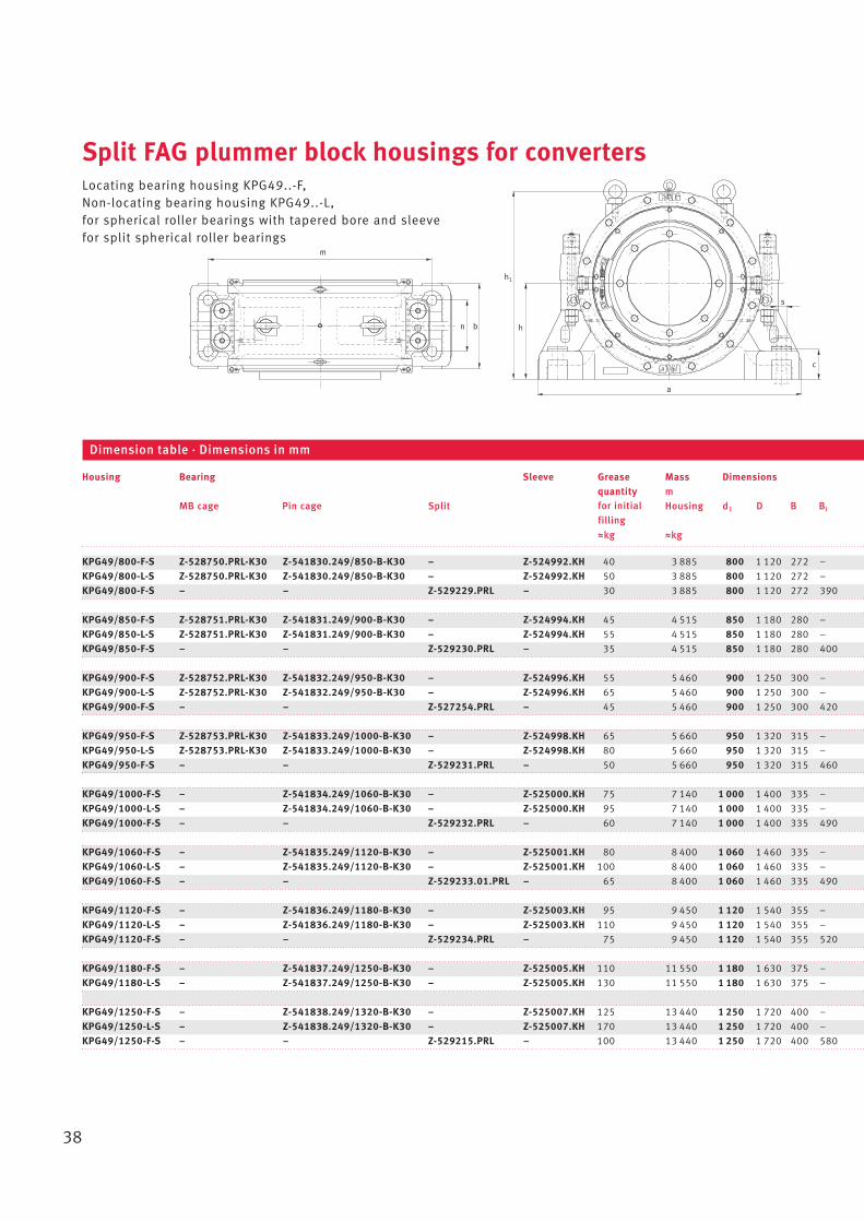
Split FAG plummer block housings for convertersLocating bearing housing KPG49..-F,Non-locating bearing housing KPG49..-L,for spherical roller bearings with tapered bore and sleevefor split spherical roller bearings
KPG49/800-F-S Z-528750.PRL-K30 Z-541830.249/850-B-K30 – Z-524992.KH 40 3 885 800 1 120 272 –
KPG49/800-L-S Z-528750.PRL-K30 Z-541830.249/850-B-K30 – Z-524992.KH 50 3 885 800 1 120 272 –
KPG49/800-F-S – – Z-529229.PRL – 30 3 885 800 1 120 272 390
KPG49/850-F-S Z-528751.PRL-K30 Z-541831.249/900-B-K30 – Z-524994.KH 45 4 515 850 1 180 280 –
KPG49/850-L-S Z-528751.PRL-K30 Z-541831.249/900-B-K30 – Z-524994.KH 55 4 515 850 1 180 280 –
KPG49/850-F-S – – Z-529230.PRL – 35 4 515 850 1 180 280 400
KPG49/900-F-S Z-528752.PRL-K30 Z-541832.249/950-B-K30 – Z-524996.KH 55 5 460 900 1 250 300 –
KPG49/900-L-S Z-528752.PRL-K30 Z-541832.249/950-B-K30 – Z-524996.KH 65 5 460 900 1 250 300 –
KPG49/900-F-S – – Z-527254.PRL – 45 5 460 900 1 250 300 420
KPG49/950-F-S Z-528753.PRL-K30 Z-541833.249/1000-B-K30 – Z-524998.KH 65 5 660 950 1 320 315 –
KPG49/950-L-S Z-528753.PRL-K30 Z-541833.249/1000-B-K30 – Z-524998.KH 80 5 660 950 1 320 315 –
KPG49/950-F-S – – Z-529231.PRL – 50 5 660 950 1 320 315 460
KPG49/1000-F-S – Z-541834.249/1060-B-K30 – Z-525000.KH 75 7 140 1 000 1 400 335 –
KPG49/1000-L-S – Z-541834.249/1060-B-K30 – Z-525000.KH 95 7 140 1 000 1 400 335 –
KPG49/1000-F-S – – Z-529232.PRL – 60 7 140 1 000 1 400 335 490
KPG49/1060-F-S – Z-541835.249/1120-B-K30 – Z-525001.KH 80 8 400 1 060 1 460 335 –
KPG49/1060-L-S – Z-541835.249/1120-B-K30 – Z-525001.KH 100 8 400 1 060 1 460 335 –
KPG49/1060-F-S – – Z-529233.01.PRL – 65 8 400 1 060 1 460 335 490
KPG49/1120-F-S – Z-541836.249/1180-B-K30 – Z-525003.KH 95 9 450 1 120 1 540 355 –
KPG49/1120-L-S – Z-541836.249/1180-B-K30 – Z-525003.KH 110 9 450 1 120 1 540 355 –
KPG49/1120-F-S – – Z-529234.PRL – 75 9 450 1 120 1 540 355 520
KPG49/1180-F-S – Z-541837.249/1250-B-K30 – Z-525005.KH 110 11 550 1 180 1 630 375 –
KPG49/1180-L-S – Z-541837.249/1250-B-K30 – Z-525005.KH 130 11 550 1 180 1 630 375 –
KPG49/1250-F-S – Z-541838.249/1320-B-K30 – Z-525007.KH 125 13 440 1 250 1 720 400 –
KPG49/1250-L-S – Z-541838.249/1320-B-K30 – Z-525007.KH 170 13 440 1 250 1 720 400 –
KPG49/1250-F-S – – Z-529215.PRL – 100 13 440 1 250 1 720 400 580
Housing Bearing Sleeve Grease Mass Dimensionsquantity m
MB cage Pin cage Split Housing d1 D B Bi
Wkg Wkg
Dimension table · Dimensions in mm
a
h1
h
s
c
bn
m
for initial
filling
39
22
1
22
1
22
1
g1
DH7d1h7
B
g3
w g2
3
g1
d2 h11 DH7d1h7
B
w g2
d2 h11
k k
g1
B
g3
DD8 d1h7
d6 d5
w g4
g3
g4
d3H8h8 t d6 d2 h11
45°
s2
d2 h11
Bi
KPG49..-F (unsplit bearing)Locating bearing
Bearing relubrication
910 – – – 195 1 960 600 220 630 325 59 – 710 1 390 – 1 600 360 M72 – – –
910 640 812 855 195 1 960 600 220 630 – 59 352,5 710 1 390 50 1 600 360 M72 745 M30~110 8
910 – – – 195 1 960 600 220 630 325 – – 710 1 390 – 1 600 360 M72 – – –
960 – – – 200 2 060 620 230 660 340 60 – 740 1 450 – 1 700 370 M80 – – –
960 675 862 905 200 2 060 620 230 660 – 60 375 740 1 450 60 1 700 370 M80 787,5 M30~110 8
960 – – – 200 2 060 620 230 660 340 – – 740 1 450 – 1 700 370 M80 – – –
1 015 – – – 210 2 200 660 250 680 350 60 – 800 1 550 – 1 820 390 M90 – – –
1 015 715 915 960 210 2 200 660 250 680 – 60 385 800 1 550 60 1 820 390 M90 832,5 M36~110 8
1 015 – – – 210 2 200 660 250 680 350 – – 800 1 550 – 1 820 390 M90 – – –
1 065 – – – 230 2 330 650 255 720 370 72,5 – 830 1 620 – 1 980 360 M90 – – –
1 065 750 965 1 010 230 2 330 650 255 720 – 72,5 412,5 830 1 620 70 1 980 360 M90 875 M36~130 8
1 065 – – – 230 2 330 650 255 720 370 – – 830 1 620 – 1 980 360 M90 – – –
1 135 – – – 245 2 450 740 275 780 400 77,5 – 880 1 710 – 2 000 460 M100 – – –
1 135 795 1 015 1 070 245 2 450 740 275 780 – 77,5 435 880 1 710 60 2 000 460 M100 927,5 M36~130 8
1 135 – – – 245 2 450 740 275 780 400 – – 880 1 710 – 2 000 460 M100 – – –
1 195 – – – 245 2 560 740 285 800 410 77,5 – 920 1 780 – 2 150 460 M100 – – –
1 195 840 1 075 1 130 245 2 560 740 285 800 – 77,5 452,5 920 1 780 70 2 150 460 M100 980 M42~140 8
1 195 – – – 245 2 560 740 285 800 410 – – 920 1 780 – 2 150 460 M100 – – –
1 260 – – – 260 2 700 780 300 820 420 82,5 – 970 1 880 – 2 300 480 M110 – – –
1 260 885 1 135 1 190 260 2 700 780 300 820 – 82,5 462,5 970 1 880 70 2 300 480 M110 1 032,5 M42~140 8
1 260 – – – 260 2 700 780 300 820 420 – – 970 1 880 – 2 300 480 M110 – – –
1 330 – – – 275 2 850 820 320 850 435 87,5 – 1 010 1 985 – 2 400 510 M110 – – –
1 330 940 1 195 1 255 275 2 850 820 320 850 – 87,5 477,5 1 010 1 985 70 2 400 510 M110 1 095 M42~150 8
1 400 – – – 290 3 000 850 340 900 460 90 – 1 080 2 100 – 2 500 520 M125 – – –
1 400 990 1 265 1 325 290 3 000 850 340 900 – 90 502,5 1 080 2 100 70 2 500 520 M125 1 155 M48~180 8
1 400 – – – 290 3 000 850 340 900 460 – – 1 080 2 100 – 2 500 520 M125 – – –
d2 d3 d5 d6 w a b c g1 g2 g3 g4 h h1 k m n s t s2 s2
DIN931 Number
KPG49..-F (split bearing)Locating bearing
Seal relubrication
KPG49..-L (unsplit bearing)Non-locating bearing
Sleeve relubrication
40
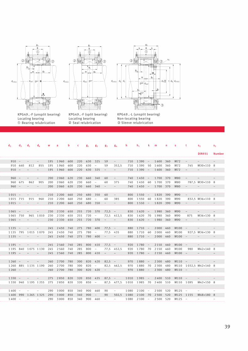
Split FAG plummer block housings for convertersLocating bearing housing KPGZ49..-F,Non-locating bearing housing KPGZ49..-L,for spherical roller bearings with cylindrical borefor split spherical roller bearings
KPGZ49/500-F-S Z-528741.PRL Z-541821.249/500 – 10 900 500 670 170 – 540 – 495 510 –
KPGZ49/500-L-S Z-528741.PRL Z-541821.249/500 – 14 900 500 670 170 – 540 375 – – 505
KPGZ49/500-F-S – – Z-537276.PRL 8 900 500 670 170 250 540 – 495 – –
KPGZ49/530-F-S Z-528742.PRL Z-541822.249/530 – 10 1 000 530 710 180 – 570 – 525 540 –
KPGZ49/530-L-S Z-528742.PRL Z-541822.249/530 – 14 1 000 530 710 180 – 570 400 – – 535
KPGZ49/530-F-S – – Z-537277.PRL 8 1 000 530 710 180 260 570 – 525 – –
KPGZ49/560-F-S Z-528743.PRL Z-541823.249/560-B – 13 1 300 560 750 190 – 600 – 555 570 –
KPGZ49/560-L-S Z-528743.PRL Z-541823.249/560-B – 15 1 300 560 750 190 – 600 420 – – 565
KPGZ49/560-F-S – – Z-537278.PRL 10 1 300 560 750 190 270 600 – 555 – –
KPGZ49/600-F-S Z-528744.PRL Z-541824.249/600-B – 15 1 500 600 800 200 – 645 – 595 610 –
KPGZ49/600-L-S Z-528744.PRL Z-541824.249/600-B – 20 1 500 600 800 200 – 645 450 – – 610
KPGZ49/600-F-S – – Z-533761.PRL 12 1 500 600 800 200 290 645 – 595 – –
KPGZ49/630-F-S – Z-541825.249/630 – 20 2 100 630 850 218 – 675 – 625 642 –
KPGZ49/630-L-S – Z-541825.249/630 – 24 2 100 630 850 218 – 675 475 – – 640
KPGZ49/630-F-S – – Z-537279.PRL 15 2 100 630 850 218 310 675 – 625 – –
KPGZ49/670-F-S Z-528746.PRL Z-541826.249/670-B – 22 2 500 670 900 230 – 720 – 665 682 –
KPGZ49/670-L-S Z-528746.PRL Z-541826.249/670-B – 25 2 500 670 900 230 – 720 505 – – 675
KPGZ49/670-F-S – – Z-537280.PRL 18 2 500 670 900 230 325 720 – 665 – –
KPGZ49/710-F-S Z-528747.PRL Z-541827.249/710-B – 26 2 700 710 950 243 – 760 – 695 722 –
KPGZ49/710-L-S Z-528747.PRL Z-541827.249/710-B – 30 2 700 710 950 243 – 760 535 – – 715
KPGZ49/710-F-S – – Z-526073.PRL 20 2 700 710 950 243 350 760 – 695 – –
KPGZ49/750-F-S Z-528748.PRL Z-541828.249/750-B – 30 2 800 750 1 000 250 – 800 – 745 762 –
KPGZ49/750-L-S Z-528748.PRL Z-541828.249/750-B – 35 2 800 750 1 000 250 – 800 565 – – 755
KPGZ49/750-F-S – – Z-533414.01.PRL 24 2 800 750 1 000 250 355 800 – 745 – –
KPGZ49/800-F-S Z-528749.PRL Z-541829.249/800-B – 35 3 300 800 1 060 258 – 860 – 795 812 –
KPGZ49/800-L-S Z-528749.PRL Z-541829.249/800-B – 40 3 300 800 1 060 258 – 860 600 – – 805
KPGZ49/800-F-S – – Z-532063.PRL 26 3 300 800 1 060 258 370 860 – 795 – –
Housing Bearing Grease Mass Dimensionsquantity m
MB cage Pin cage Split Housing d D B Bi d2 d3 d4 d5 d6
Wkg Wkg
Dimension table · Dimensions in mm
a
h1
h
s
c
bn
m
for initial
filling

41
22
1
22
1
22
1
d2 h11 d4DH7dm6H7m6
B
g3
w g2
45°
g1
d5 d2 h11
k k
g1
B
g3
wL g4
d3H8h8
DD8
dm6
t d6 d2 h11
g3
s2
g1
d2 h11 d4DH7dm6H7m6
Bi
w g2
3
B
KPGZ49..-F (unsplit bearing)Locating bearing
Bearing relubrication
125 – 1 170 375 130 400 210 40 – 425 820 – 975 230 M42 – – –
– 85 1 170 375 130 400 – 40 230 425 820 40 975 230 M42 437,5 M20~70 8
125 – 1 170 375 130 400 210 – – 425 820 – 975 230 M42 – – –
130 – 1 240 400 140 410 215 40 – 450 875 – 1 050 240 M42 – – –
– 90 1 240 400 140 410 – 40 235 450 875 40 1 050 240 M42 465 M20~70 8
130 – 1 240 400 140 410 215 – – 450 875 – 1 050 240 M42 – – –
135 – 1 320 420 145 420 220 40 – 475 930 – 1 100 255 M48 – – –
– 95 1 320 420 145 420 – 40 240 475 930 40 1 100 255 M48 490 M20~70 8
135 – 1 320 420 145 420 220 – – 475 930 – 1 100 255 M48 – – –
145 – 1 400 440 155 460 240 45 – 500 980 – 1 150 270 M52 – – –
– 100 1 400 440 155 460 – 45 260 500 980 40 1 150 270 M52 525 M20~80 8
145 – 1 400 440 155 460 240 – – 500 980 – 1 150 270 M52 – – –
155 – 1 500 480 165 480 250 46 – 535 1 040 – 1 225 295 M56 – – –
– 109 1 500 480 165 480 – 46 270 535 1 040 40 1 225 295 M56 552,5 M20~80 8
155 – 1 500 480 165 480 250 – – 535 1 040 – 1 225 295 M56 – – –
162,5 – 1 570 500 175 500 260 47,5 – 570 1 110 – 1 300 310 M56 – – –
– 115 1 570 500 175 500 – 47,5 280 570 1 110 40 1 300 310 M56 587,5 M24~90 8
162,5 – 1 570 500 175 500 260 – – 570 1 110 – 1 300 310 M56 – – –
175 – 1 660 535 185 560 290 53,5 – 600 1 170 – 1 375 325 M64 – – –
– 121,5 1 660 535 185 560 – 53,5 317,5 600 1 170 50 1 375 325 M64 622,5 M24~90 8
175 – 1 660 535 185 560 290 – – 600 1 170 – 1 375 325 M64 – – –
177,5 – 1 750 550 195 590 305 52,5 – 630 1 240 – 1 450 335 M64 – – –
– 125 1 750 550 195 590 – 52,5 332,5 630 1 240 50 1 450 335 M64 657,5 M30~100 8
177,5 – 1 750 550 195 590 305 – – 630 1 240 – 1 450 335 M64 – – –
185 – 1 850 570 205 600 310 56 – 670 1 310 – 1 550 345 M72 – – –
– 129 1 850 570 205 600 – 56 337,5 670 1 310 50 1 550 345 M72 700 M30~100 8
185 – 1 850 570 205 600 310 – – 670 1 310 – 1 550 345 M72 – – –
w wL a b c g1 g2 g3 g4 h h1 k m n s t s2 s2
DIN931 Number
KPGZ49..-F (split bearing)Locating bearing
Seal relubrication
KPGZ49..-L (unsplit bearing)Non-locating bearing
Sleeve relubrication
42
Split FAG plummer block housings for convertersLocating bearing housing KPGZ49..-F,Non-locating bearing housing KPGZ49..-L,for spherical roller bearings with cylindrical borefor split spherical roller bearings
KPGZ49/850-F-S Z-528750.PRL Z-541830.249/850-B – 40 3 700 850 1 120 272 – 910 – 845 862 –
KPGZ49/850-L-S Z-528750.PRL Z-541830.249/850-B – 50 3 700 850 1 120 272 – 910 640 – – 855
KPGZ49/850-F-S – – Z-537281.PRL 30 3 700 850 1 120 272 385 910 – 845 – –
KPGZ49/900-F-S Z-528751.PRL Z-541831.249/900-B – 45 4 300 900 1 180 280 – 960 – 895 912 –
KPGZ49/900-L-S Z-528751.PRL Z-541831.249/900-B – 55 4 300 900 1 180 280 – 960 675 – – 905
KPGZ49/900-F-S – – Z-537282.PRL 35 4 300 900 1 180 280 390 960 – 895 – –
KPGZ49/950-F-S Z-528752.PRL Z-541832.249/950-B - 55 5 200 950 1 250 300 – 1 015 – 945 965 –
KPGZ49/950-L-S Z-528752.PRL Z-541832.249/950-B – 65 5 200 950 1 250 300 – 1 015 715 – – 960
KPGZ49/950-F-S – – Z-534826.PRL 45 5 200 950 1 250 300 410 1 015 – 945 – –
KPGZ49/1000-F-S Z-528753.PRL Z-541833.249/1000-B – 65 5 770 1 000 1 320 315 – 1 065 – 985 1 015 –
KPGZ49/1000-L-S Z-528753.PRL Z-541833.249/1000-B – 80 5 770 1 000 1 320 315 – 1 065 750 – – 1 010
KPGZ49/1000-F-S – – Z-533567.PRL 50 5 770 1 000 1 320 315 450 1 065 – 985 – –
KPGZ49/1060-F-S – Z-541834.249/1060-B – 75 6 800 1 060 1 400 335 – 1 135 – 1 055 1 075 –
KPGZ49/1060-L-S – Z-541834.249/1060-B – 95 6 800 1 060 1 400 335 – 1 135 795 – – 1 070
KPGZ49/1060-F-S – – Z-537283.PRL 60 6 800 1 060 1 400 335 475 1 135 – 1 055 – –
KPGZ49/1120-F-S – Z-541835.249/1120-B – 80 8 000 1 120 1 460 335 – 1 195 – 1 115 1 135 –
KPGZ49/1120-L-S – Z-541835.249/1120-B – 100 8 000 1 120 1 460 335 – 1 195 840 – – 1 130
KPGZ49/1120-F-S – – Z-537284.PRL 65 8 000 1 120 1 460 335 475 1 195 – 1 115 – –
KPGZ49/1180-F-S – Z-541836.249/1180-B – 95 9 000 1 180 1 540 355 – 1 260 – 1 175 1 195 –
KPGZ49/1180-L-S – Z-541836.249/1180-B – 110 9 000 1 180 1 540 355 – 1 260 885 – – 1 190
KPGZ49/1180-F-S – – Z-536806.PRL 75 9 000 1 180 1 540 355 500 1 260 – 1 175 – –
KPGZ49/1250-F-S – Z-541837.249/1250-B – 110 11 000 1 250 1 630 375 – 1 330 – 1 245 1 265 –
KPGZ49/1250-L-S – Z-541837.249/1250-B – 130 11 000 1 250 1 630 375 – 1 330 940 – – 1 255
KPGZ49/1250-F-S – – Z-537285.PRL 85 11 000 1 250 1 630 375 545 1 330 – 1 245 – –
KPGZ49/1320-F-S – Z-541838.249/1320-B – 125 12 800 1 320 1 720 400 – 1 400 – 1 315 1 335 –
KPGZ49/1320-L-S – Z-541838.249/1320-B – 170 12 800 1 320 1 720 400 – 1 400 990 – – 1 325
KPGZ49/1320-F-S – – Z-545161.PRL 100 12 800 1 320 1 720 400 580 1 400 – 1 315 – –
Housing Bearing Grease Mass Dimensionsquantity m
MB cage Pin cage Split Housing d D B Bi d2 d3 d4 d5 d6
Wkg Wkg
Dimension table · Dimensions in mm
a
h1
h
s
c
bn
m
for initial
filling
43
22
1
22
1
22
1
d2 h11 d4DH7dm6H7m6
B
g3
w g2
45°
g1
d5 d2 h11
k k
g1
B
g3
wL g4
d3H8h8
DD8
dm6
t d6 d2 h11
g3
s2
g1
d2 h11 d4DH7dm6H7m6
Bi
w g2
3
B
KPGZ49..-F (unsplit bearing)Locating bearing
Bearing relubrication
192,5 – 1 960 600 220 630 325 56,5 – 710 1 390 – 1 600 360 M72 – – –
– 136 1 960 600 220 630 – 56,5 352,5 710 1 390 50 1 600 360 M72 745 M30~110 8
192,5 – 1 960 600 220 630 325 – – 710 1 390 – 1 600 360 M72 – – –
195 – 2 060 620 230 660 340 55 – 740 1 450 – 1 700 370 M80 – – –
– 140 2 060 620 230 660 – 55 375 740 1 450 60 1 700 370 M80 787,5 M30~110 8
195 – 2 060 620 230 660 340 – – 740 1 450 – 1 700 370 M80 – – –
205 – 2 200 660 250 680 350 55 – 800 1 550 – 1 820 390 M90 – – –
– 150 2 200 660 250 680 – 55 385 800 1 550 60 1 820 390 M90 832,5 M36~110 8
205 – 2 200 660 250 680 350 55 – 800 1 550 – 1 820 390 M90 – – –
225 – 2 330 650 255 720 370 67,5 – 830 1 620 – 1 980 360 M90 – – –
– 157,5 2 330 650 255 720 – 67,5 412,5 830 1 620 70 1 980 360 M90 875 M36~130 8
225 – 2 330 650 255 720 370 – – 830 1 620 – 1 980 360 M90 – – –
237,5 – 2 450 740 275 780 400 70 – 880 1 710 – 2 000 460 M100 – – –
– 167,5 2 450 740 275 780 – 70 435 880 1 710 60 2 000 460 M100 927,5 M36~130 8
237,5 – 2 450 740 275 780 400 – – 880 1 710 – 2 000 460 M100 – – –
237,5 – 2 560 740 285 800 410 70 – 920 1 780 – 2 150 460 M100 – – –
– 167,5 2 560 740 285 800 – 70 452,5 920 1 780 70 2 150 460 M100 980 M42~140 8
237,5 – 2 560 740 285 800 410 – – 920 1 780 – 2 150 460 M100 – – –
250 – 2 700 780 300 820 420 72,5 – 970 1 880 – 2 300 480 M110 – – –
– 177,5 2 700 780 300 820 – 72,5 462,5 970 1 880 70 2 300 480 M110 1 032,5 M42~140 8
250 – 2 700 780 300 820 420 – – 970 1 880 – 2 300 480 M110 – – –
272,5 – 2 850 820 320 850 435 85 – 1 010 1 985 – 2 400 510 M110 – – –
– 187,5 2 850 820 320 850 – 85 477,5 1 010 1 985 70 2 400 510 M110 1 095 M42~150 8
272,5 – 2 850 820 320 850 435 – – 1 010 1 985 – 2 400 510 M110 – – –
290 – 3 000 850 340 900 460 90 – 1 080 2 100 – 2 500 520 M125 – – –
– 200 3 000 850 340 900 – 90 502,5 1 080 2 100 70 2 500 520 M125 1 155 M48~180 8
290 – 3 000 850 340 900 460 – – 1 080 2 100 – 2 500 520 M125 – – –
w wL a b c g1 g2 g3 g4 h h1 k m n s t s2 s2
DIN931 Number
KPGZ49..-F (split bearing)Locating bearing
Seal relubrication
KPGZ49..-L (unsplit bearing)Non-locating bearing
Sleeve relubrication
7 References
We work together with all manufacturers of converter plants.To date, more than 200 convertersworldwide have been fitted withFAG bearings and housings. Examples of new converters fittedwith FAG rolling bearings and housings can be found in “Examplesfrom Application Engineering”,which we will send to you onrequest. Furthermore, we supply replacementbearings for existing converterplants on an ongoing basis.
8 Other publications
Catalogue HR 1 Rolling BearingsCatalogue GL1 Large Size Bearings
WL 80 100 Mounting of rolling bearingsWL 80 250 FAG equipment and services for the mounting
and maintenance of rolling bearingsWL 81 115 Lubrication of rolling bearingsWL 82 102 Rolling bearing damage
TPI WL 80-50 FAG pressure generatorsTPI WL 80-72 Reconditioning and repair of rolling bearingsTPI 168 Arcanol rolling bearing greases
CD-medias® Electronic INA/FAG bearing catalogue
References · Other publications
44
9 Design brief
Original equipment For which operatorReplacement Built by; year of constructionCode wordConverter sizeDesign – Supporting ring Single-piece/multi-piece/closed/open
– Slag removal By burning off/knocking off– Drive Unilateral/bilateral
Systems – Oxygen top blowing – Oxygen bottom blowing– Combined blowing process– Special developments
Sub-assembly – Housing – With displacement sleeve KPG49/KPGZ49– With linear bearing– Other (double displacement sleeve, cylindrical roller bearing)
– Bearing – Spherical roller bearing– Spherical roller bearing, split
Load collective (Bearing loads F0r and F0a must be determined for every bearing location) – Maximum radial load for locating bearing F0rF =– Maximum radial load for non-locating bearing F0rL =– Maximum external axial load F0a =
Conditions of motion Speed; swivel angle; numver of swivelsEnvironmental influences Bearing ambient temperature, moisture, dust etc.Lubrication Grease lubrication – Grease grade
– Relubrication quantity– Relubrication interval
Sealing – High-pressure packing– US rubber profile
Installation space (if possible, enclose fitting drawing or sketch) – Fitting location Locating bearing/non-locating bearing– Bearing seat Cylindrical/location on sleeve– Seat diameter Shaft/housing/fits– Bearing design Split/unsplit
Other requirements – Design – Max. angular misalignment– Mounting requirements– Max. axial displacement capacity– Lubricant distribution– Wearing parts– Required housing material– Temperature of trunnion and housing
– Technical specifications – Packaging– Housing design– Preservation– Measurement record– Acceptance inspection certificates– Plant certificates
– Other – Warranty– Mounting instruction– Language
Design brief
45

Notes
46

Notes
47

Notes
48

MAT
NR
0350
4713
5-00
00 /
TPI
148
/ G
B-D
/ 2
0091
01 /
Pri
nted
in G
erm
any
by M
ande
lkow
Every care has been taken to ensure the
correctness of the information contained in
this publication but no liability can be
accepted for any errors or omissions.
We reserve the right to make technical
changes.
© Schaeffler KG · 2009, October
This publication or parts thereof may not
be reproduced without our permission.
TPI 148 GB-D
Schaeffler KG
Georg-Schäfer-Straße 30
97421 Schweinfurt (Germany)
Internet www.fag.com
E-Mail [email protected]
Phone +49 9721 91-0
Fax +49 9721 91-3435