Embed Size (px)
Citation preview
DES
Y 28
/Jun
e/20
10 O
lym
pus
Col
labo
ratio
n m
eetin
gS.
Frul
lani
/ R
ome
grou
pac
tivity
3
1
Rome group activity since lastmeeting (3)
Salvatore Frullani / INFN-Rome Sanità Group
OLYMPUS CollaborationDESY 28/June/2010
DES
Y 28
/Jun
e/20
10 O
lym
pus
Col
labo
ratio
n m
eetin
gS.
Frul
lani
/ R
ome
grou
pac
tivity
3
2
Outline
• MWPC electronics– Request , what will be provided– Safe working conditions for electronics
• Monitor GEM electronics– INFN design for GEM readout plane (40x50
cm2) sent, upon request, to M. Kohl – GEM performances at PREX, simulation
studies– GEM electronics– Request for GEM Monitor electronics– Test beam plans in July
DES
Y 28
/Jun
e/20
10 O
lym
pus
Col
labo
ratio
n m
eetin
gS.
Frul
lani
/ R
ome
grou
pac
tivity
3
3
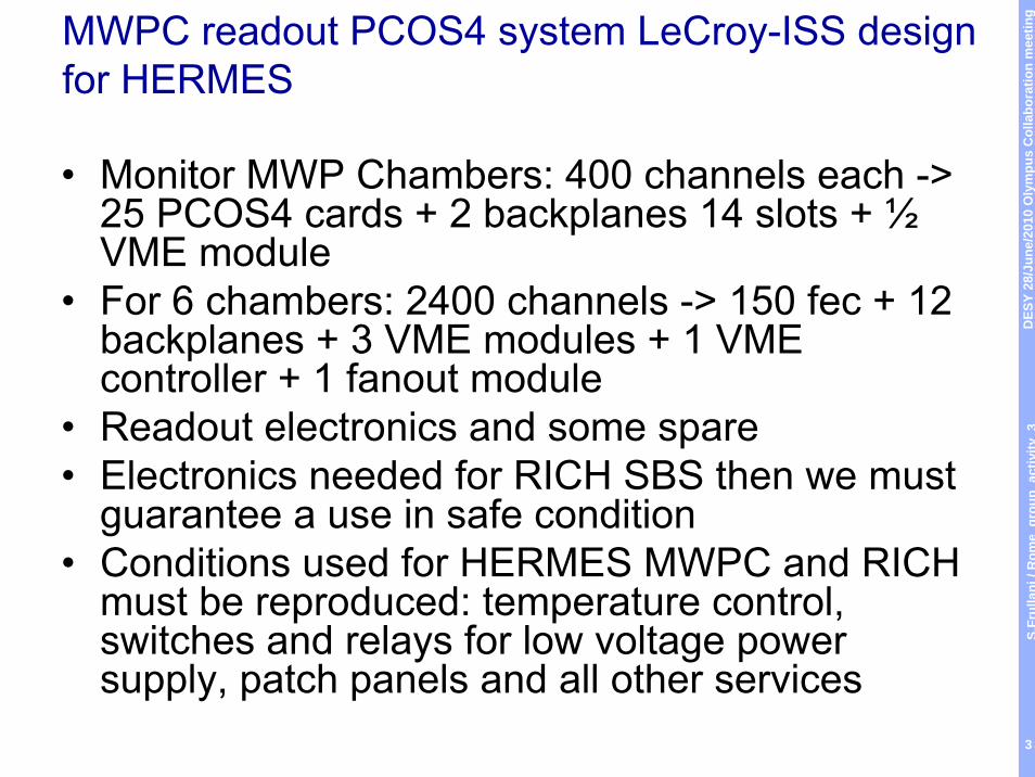
MWPC readout PCOS4 system LeCroy-ISS design for HERMES
• Monitor MWP Chambers: 400 channels each -> 25 PCOS4 cards + 2 backplanes 14 slots + ½ VME module
• For 6 chambers: 2400 channels -> 150 fec + 12 backplanes + 3 VME modules + 1 VME controller + 1 fanout module
• Readout electronics and some spare• Electronics needed for RICH SBS then we must
guarantee a use in safe condition• Conditions used for HERMES MWPC and RICH
must be reproduced: temperature control, switches and relays for low voltage power supply, patch panels and all other services
DES
Y 28
/Jun
e/20
10 O
lym
pus
Col
labo
ratio
n m
eetin
gS.
Frul
lani
/ R
ome
grou
pac
tivity
3
4
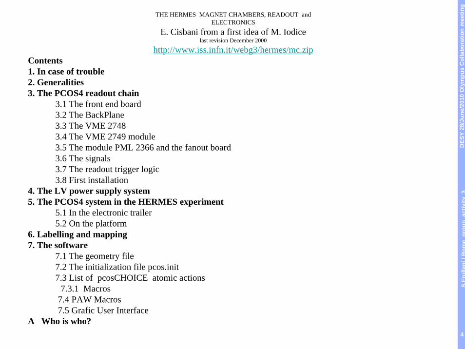
THE HERMES MAGNET CHAMBERS, READOUT andELECTRONICS
E. Cisbani from a first idea of M. Iodicelast revision December 2000
http://www.iss.infn.it/webg3/hermes/mc.zipContents1. In case of trouble2. Generalities3. The PCOS4 readout chain
3.1 The front end board3.2 The BackPlane3.3 The VME 27483.4 The VME 2749 module3.5 The module PML 2366 and the fanout board3.6 The signals3.7 The readout trigger logic3.8 First installation
4. The LV power supply system5. The PCOS4 system in the HERMES experiment
5.1 In the electronic trailer5.2 On the platform
6. Labelling and mapping7. The software
7.1 The geometry file7.2 The initialization file pcos.init7.3 List of pcosCHOICE atomic actions
7.3.1 Macros7.4 PAW Macros7.5 Grafic User Interface
A Who is who?
DES
Y 28
/Jun
e/20
10 O
lym
pus
Col
labo
ratio
n m
eetin
gS.
Frul
lani
/ R
ome
grou
pac
tivity
3
5
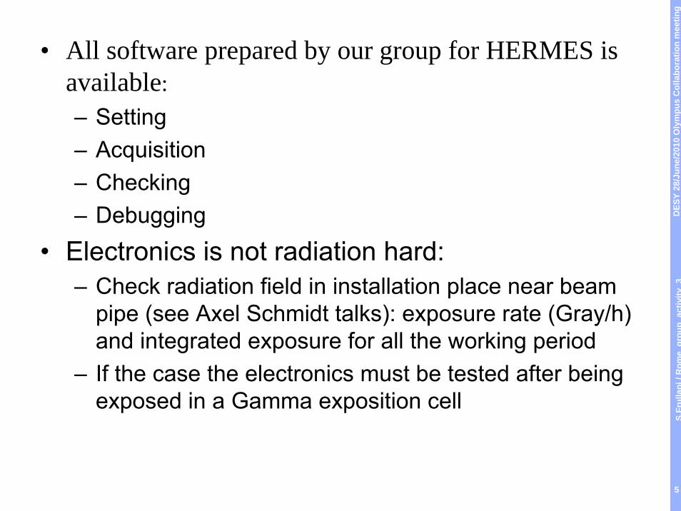
• All software prepared by our group for HERMES isavailable:– Setting– Acquisition– Checking– Debugging
• Electronics is not radiation hard:– Check radiation field in installation place near beam
pipe (see Axel Schmidt talks): exposure rate (Gray/h) and integrated exposure for all the working period
– If the case the electronics must be tested after beingexposed in a Gamma exposition cell
DES
Y 28
/Jun
e/20
10 O
lym
pus
Col
labo
ratio
n m
eetin
gS.
Frul
lani
/ R
ome
grou
pac
tivity
3
6
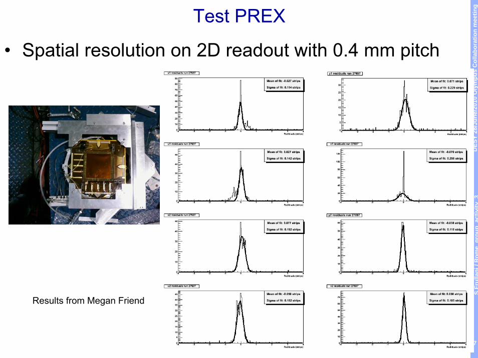
GEM: PREX gaining experience
• Useful to introduce people in data reduction and analysis (help from Rome group – Guido MariaUrciuoli – and JLab group)
• Confirmed GEM performances : 100 μm resolutionfor a 400 μm pitch
DES
Y 28
/Jun
e/20
10 O
lym
pus
Col
labo
ratio
n m
eetin
gS.
Frul
lani
/ R
ome
grou
pac
tivity
3
7
Test PREX
• Spatial resolution on 2D readout with 0.4 mm pitch
Results from Megan Friend
DES
Y 28
/Jun
e/20
10 O
lym
pus
Col
labo
ratio
n m
eetin
gS.
Frul
lani
/ R
ome
grou
pac
tivity
3
8
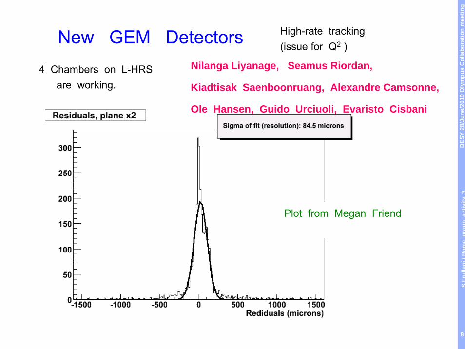
Nilanga Liyanage, Seamus Riordan,
Kiadtisak Saenboonruang, Alexandre Camsonne,
Ole Hansen, Guido Urciuoli, Evaristo Cisbani
Plot from Megan Friend
High-rate tracking (issue for Q2 )
4 Chambers on L-HRS are working.
New GEM Detectors
DES
Y 28
/Jun
e/20
10 O
lym
pus
Col
labo
ratio
n m
eetin
gS.
Frul
lani
/ R
ome
grou
pac
tivity
3
9
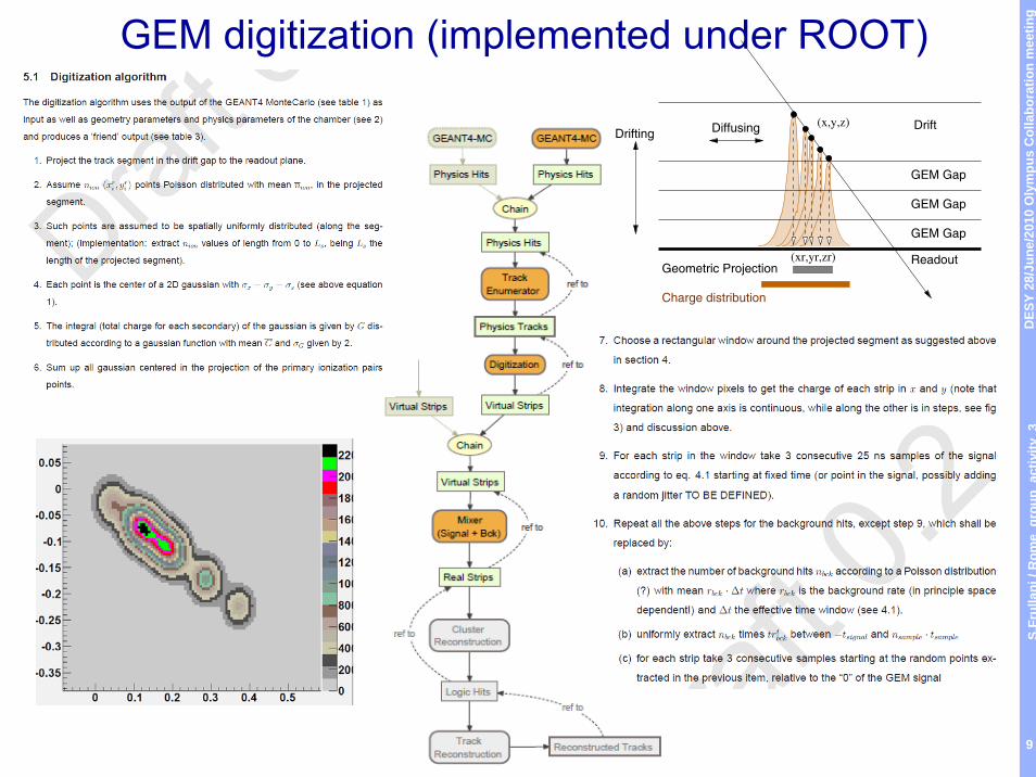
GEM digitization (implemented under ROOT)
Geometric Projection
Charge distribution
Drift
GEM Gap
GEM Gap
GEM Gap
Readout
DiffusingDrifting(x,y,z)
(xr,yr,zr)
DES
Y 28
/Jun
e/20
10 O
lym
pus
Col
labo
ratio
n m
eetin
gS.
Frul
lani
/ R
ome
grou
pac
tivity
3
10
Monitor GEM project
• Upon request from Michael Kohl, sent design of our 40x50 cm2 module for SBS GEM in Gerbv files in order to be of help for the design of 10x10 cm2 (1/20 area) OLYMPUS GEM Monitor
• Same solution to interface electronic FEC adopted (positive solution)
DES
Y 28
/Jun
e/20
10 O
lym
pus
Col
labo
ratio
n m
eetin
gS.
Frul
lani
/ R
ome
grou
pac
tivity
3
11
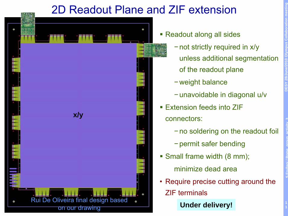
2D Readout Plane and ZIF extension
Readout along all sides
−not strictly required in x/yunless additional segmentation of the readout plane
−weight balance
−unavoidable in diagonal u/v
Extension feeds into ZIF connectors:
−no soldering on the readout foil
−permit safer bending
Small frame width (8 mm);
minimize dead area
• Require precise cutting around the ZIF terminals
Rui De Oliveira final design based on our drawing
x/y
Under delivery!
DES
Y 28
/Jun
e/20
10 O
lym
pus
Col
labo
ratio
n m
eetin
gS.
Frul
lani
/ R
ome
grou
pac
tivity
3
1210-06-10 Francesco Noto 12
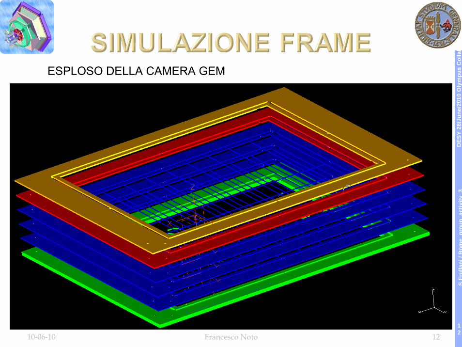
ESPLOSO DELLA CAMERA GEM
DES
Y 28
/Jun
e/20
10 O
lym
pus
Col
labo
ratio
n m
eetin
gS.
Frul
lani
/ R
ome
grou
pac
tivity
3
1310-06-10 Francesco Noto 13
DES
Y 28
/Jun
e/20
10 O
lym
pus
Col
labo
ratio
n m
eetin
gS.
Frul
lani
/ R
ome
grou
pac
tivity
3
14
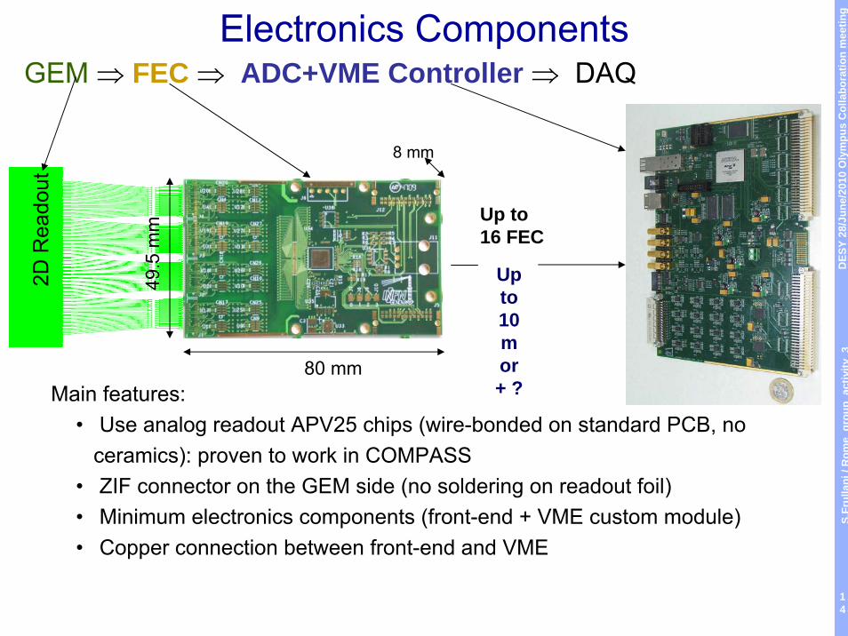
Electronics ComponentsGEM ⇒ FEC ⇒ ADC+VME Controller ⇒ DAQ
Main features:• Use analog readout APV25 chips (wire-bonded on standard PCB, no
ceramics): proven to work in COMPASS• ZIF connector on the GEM side (no soldering on readout foil) • Minimum electronics components (front-end + VME custom module)• Copper connection between front-end and VME
2D R
eado
ut
Up to 10m or + ?
80 mm
49.5
mm
8 mm
Up to16 FEC
DES
Y 28
/Jun
e/20
10 O
lym
pus
Col
labo
ratio
n m
eetin
gS.
Frul
lani
/ R
ome
grou
pac
tivity
3
15
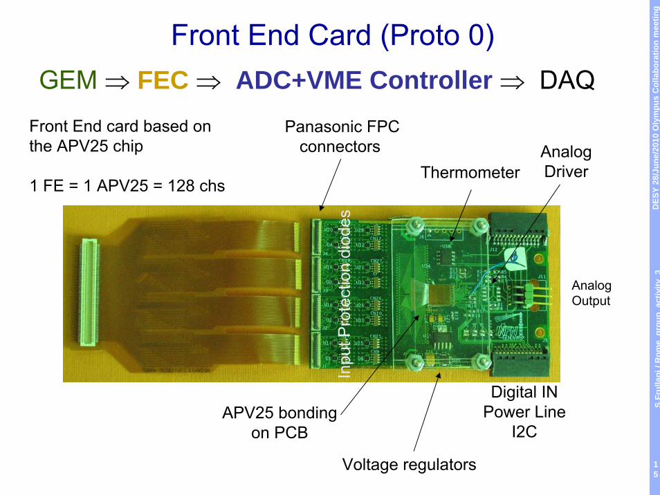
Front End Card (Proto 0)GEM ⇒ FEC ⇒ ADC+VME Controller ⇒ DAQ
Front End card based onthe APV25 chip
1 FE = 1 APV25 = 128 chs
AnalogOutput
Panasonic FPCconnectors
Inpu
t Pro
tect
ion
diod
es
APV25 bondingon PCB
Voltage regulators
AnalogDriverThermometer
Digital INPower Line
I2C
DES
Y 28
/Jun
e/20
10 O
lym
pus
Col
labo
ratio
n m
eetin
gS.
Frul
lani
/ R
ome
grou
pac
tivity
3
16
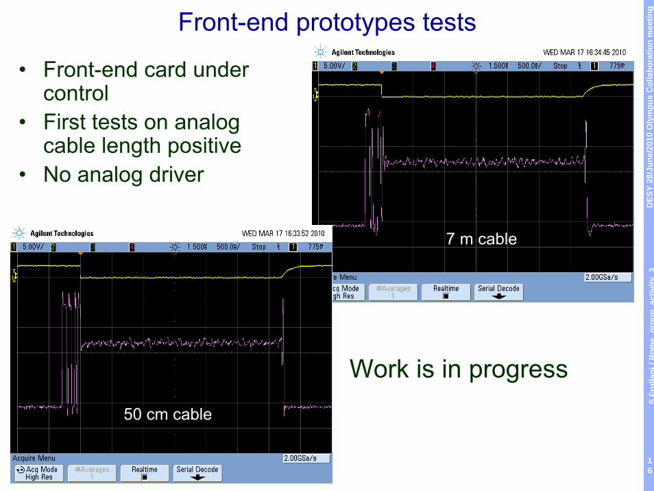
Front-end prototypes tests
50 cm cable
7 m cable
Work is in progress
• Front-end card under control
• First tests on analog cable length positive
• No analog driver
DES
Y 28
/Jun
e/20
10 O
lym
pus
Col
labo
ratio
n m
eetin
gS.
Frul
lani
/ R
ome
grou
pac
tivity
3
17
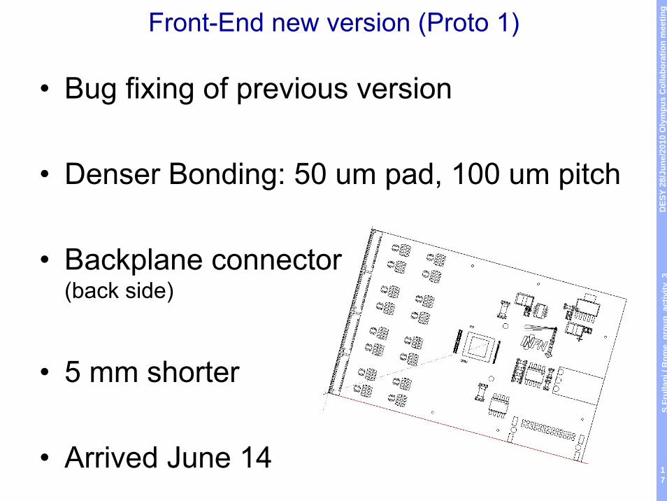
Front-End new version (Proto 1)
• Bug fixing of previous version
• Denser Bonding: 50 um pad, 100 um pitch
• Backplane connector(back side)
• 5 mm shorter
• Arrived June 14
DES
Y 28
/Jun
e/20
10 O
lym
pus
Col
labo
ratio
n m
eetin
gS.
Frul
lani
/ R
ome
grou
pac
tivity
3
18
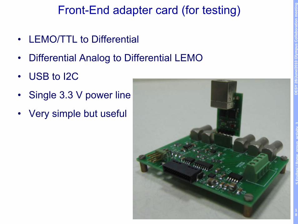
Front-End adapter card (for testing)
• LEMO/TTL to Differential
• Differential Analog to Differential LEMO
• USB to I2C
• Single 3.3 V power line
• Very simple but useful
DES
Y 28
/Jun
e/20
10 O
lym
pus
Col
labo
ratio
n m
eetin
gS.
Frul
lani
/ R
ome
grou
pac
tivity
3
19
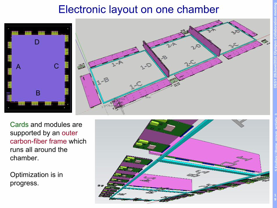
Electronic layout on one chamber
Cards and modules are supported by an outer carbon-fiber frame which runs all around the chamber.
Optimization is in progress.
A C
B
D
DES
Y 28
/Jun
e/20
10 O
lym
pus
Col
labo
ratio
n m
eetin
gS.
Frul
lani
/ R
ome
grou
pac
tivity
3
20
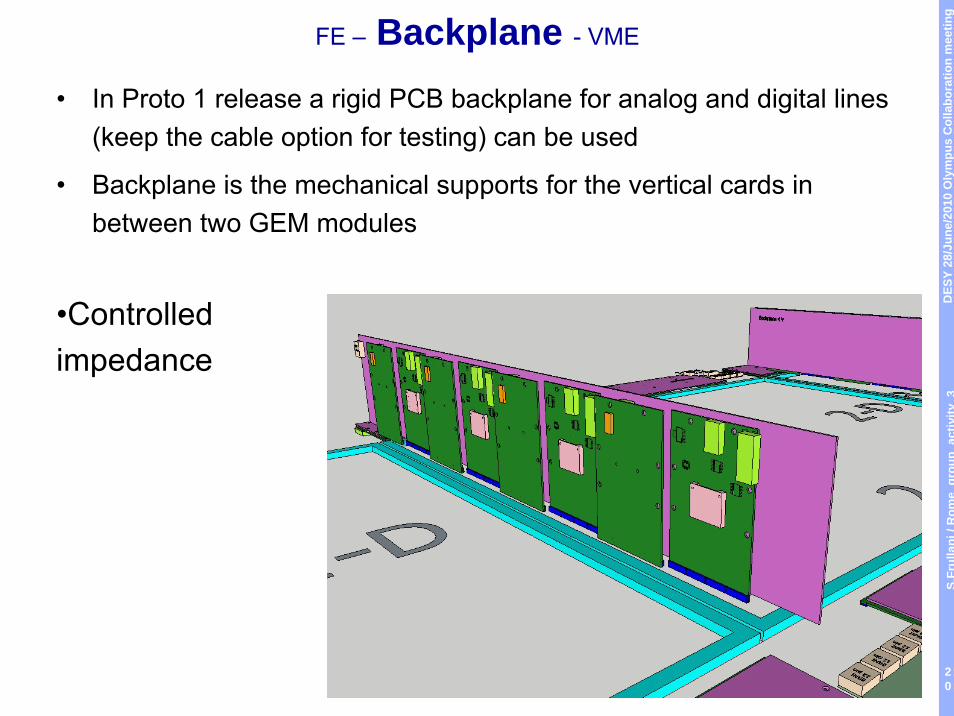
FE – Backplane - VME
• In Proto 1 release a rigid PCB backplane for analog and digital lines (keep the cable option for testing) can be used
• Backplane is the mechanical supports for the vertical cards in between two GEM modules
•Controlledimpedance
DES
Y 28
/Jun
e/20
10 O
lym
pus
Col
labo
ratio
n m
eetin
gS.
Frul
lani
/ R
ome
grou
pac
tivity
3
21
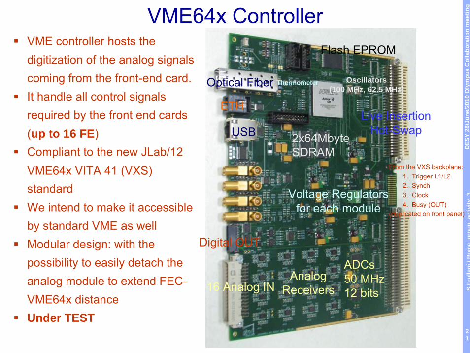
VME64x ControllerVME controller hosts the digitization of the analog signals coming from the front-end card.It handle all control signals required by the front end cards (up to 16 FE)Compliant to the new JLab/12 VME64x VITA 41 (VXS) standardWe intend to make it accessible by standard VME as wellModular design: with the possibility to easily detach the analog module to extend FEC-VME64x distanceUnder TEST
From the VXS backplane:1. Trigger L1/L22. Synch3. Clock4. Busy (OUT)
(duplicated on front panel)
Digital OUT
16 Analog INAnalog
Receivers
ADCs50 MHz12 bits
USB
ETH
Optical Fiber
2x64MbyteSDRAM
Live InsertionHot-Swap
Oscillators(100 MHz, 62.5 MHz)
Flash EPROM
Thermometer
Voltage Regulatorsfor each module
DES
Y 28
/Jun
e/20
10 O
lym
pus
Col
labo
ratio
n m
eetin
gS.
Frul
lani
/ R
ome
grou
pac
tivity
3
22
• Firmware on Verilog (under test):– VME-32 bit interface (64-bit interface very
preliminary)– USB-interface (VME and USB share the same
resources) – PLL configuration interface (APV-ADC clock phasing) – I2C master interface– Trigger handler (very simple) via front panel LEMO– ADC serial configuration interface and de-serializer– APV25 frame decoder; value stored on a FIFO
accessible from VME and USB.– Single channel histogram (useful for delay tuning ...)– Front end test signals generator
VME64x Controller / ALTERA Firmware
DES
Y 28
/Jun
e/20
10 O
lym
pus
Col
labo
ratio
n m
eetin
gS.
Frul
lani
/ R
ome
grou
pac
tivity
3
23
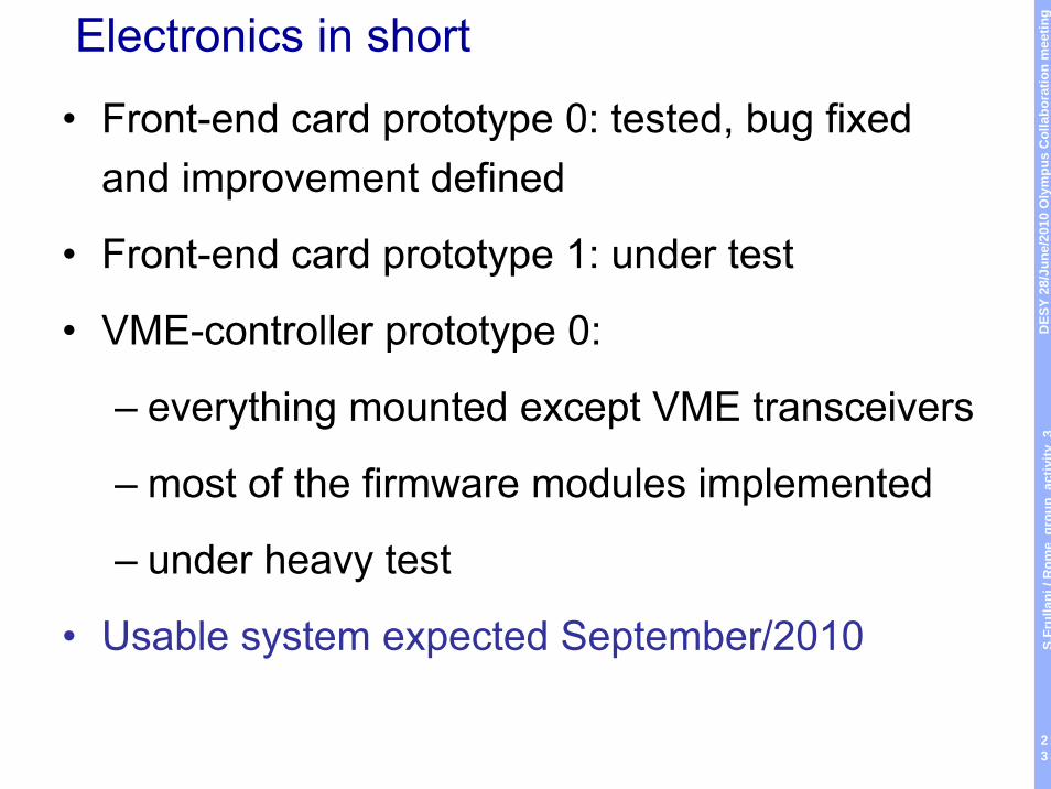
Electronics in short
• Front-end card prototype 0: tested, bug fixed and improvement defined
• Front-end card prototype 1: under test
• VME-controller prototype 0:
– everything mounted except VME transceivers
– most of the firmware modules implemented
– under heavy test
• Usable system expected September/2010
DES
Y 28
/Jun
e/20
10 O
lym
pus
Col
labo
ratio
n m
eetin
gS.
Frul
lani
/ R
ome
grou
pac
tivity
3
24
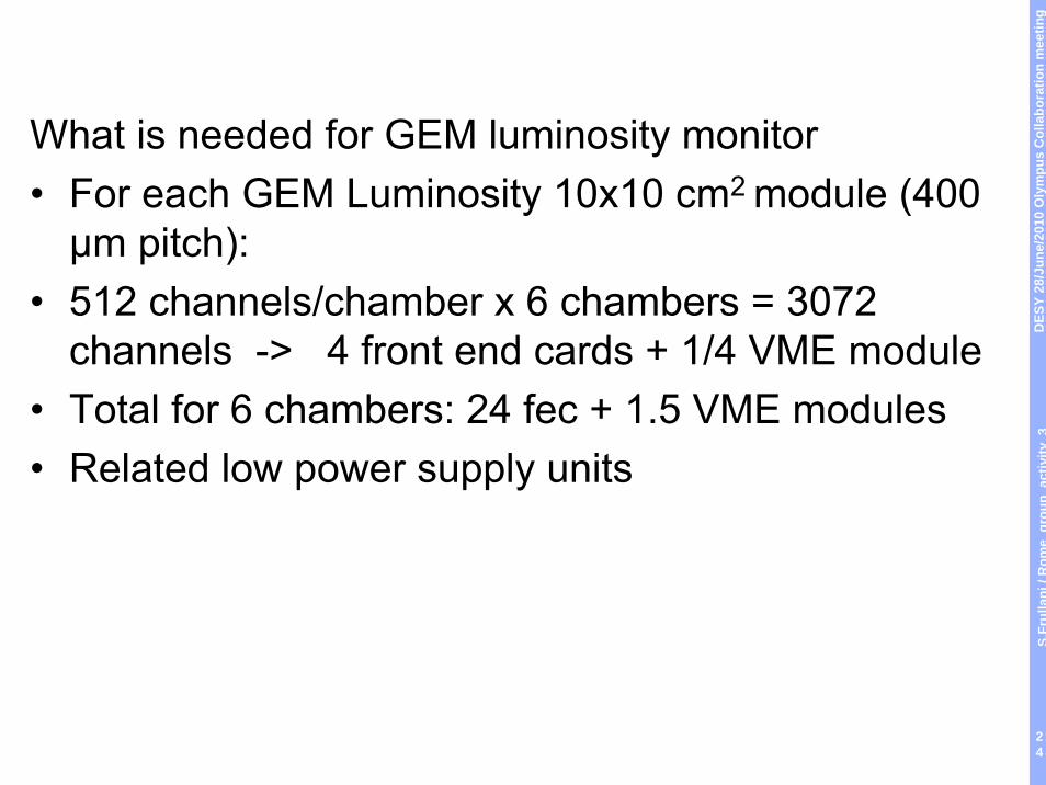
What is needed for GEM luminosity monitor• For each GEM Luminosity 10x10 cm2 module (400 μm pitch):
• 512 channels/chamber x 6 chambers = 3072 channels -> 4 front end cards + 1/4 VME module
• Total for 6 chambers: 24 fec + 1.5 VME modules• Related low power supply units
DES
Y 28
/Jun
e/20
10 O
lym
pus
Col
labo
ratio
n m
eetin
gS.
Frul
lani
/ R
ome
grou
pac
tivity
3
25
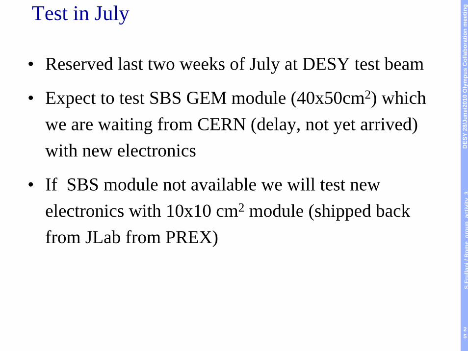
Test in July
• Reserved last two weeks of July at DESY test beam
• Expect to test SBS GEM module (40x50cm2) which we are waiting from CERN (delay, not yet arrived) with new electronics
• If SBS module not available we will test new electronics with 10x10 cm2 module (shipped back from JLab from PREX)