Embed Size (px)
Citation preview
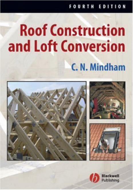

ROOF CONSTRUCTIONAND LOFT CONVERSION
FOURTH EDITION
C.N. Mindham

ROOF CONSTRUCTIONAND LOFT CONVERSION
FOURTH EDITION
C.N. Mindham
© C.N. Mindham 1986, 1988, 1994, 1999, 2006
Blackwell Publishing Ltd editorial offices:Blackwell Publishing Ltd, 9600 Garsington Road, Oxford OX4 2DQ, UK
Tel: +44 (0)1865 776868Blackwell Publishing Inc., 350 Main Street, Malden, MA 02148-5020, USA
Tel: +1 781 388 8250Blackwell Publishing Asia Pty Ltd, 550 Swanston Street, Carlton, Victoria 3053, Australia
Tel: +61 (0)3 8359 1011
The right of the Author to be identifi ed as the Author of this Work has been asserted in accordance with the Copyright, Designs and Patents Act 1988.
All rights reserved. No part of this publication may be reproduced, stored in a retrieval system, or transmitted, in any form or by any means, electronic, mechanical, photocopy-ing, recording or otherwise, except as permitted by the UK Copyright, Designs and Patents Act 1988, without the prior permission of the publisher.
First edition published under the title Roof Construction for Dwellings by Collins Professional and Technical Books 1986
First edition revised and published by BSP Professional Books 1988Second edition published by Blackwell Science 1994Third edition published 1999Fourth edition published by Blackwell Publishing Ltd 2006
ISBN-10: 1-4051-3963-3ISBN-13: 978-1-4051-3963-2
Library of Congress Cataloging-in-Publication Data
Mindham, C. N. (Chris N.)Roof construction and loft conversion / C.N. Mindham. – 4th ed.
p. cm.Includes bibliographical references and index.ISBN-13: 978-1-4051-3963-2 (alk. paper)ISBN-10: 1-4051-3963-3 (alk. paper)1. Roofs–Design and construction. 2. Framing (Building) 3. Lofts–Remodeling.I. Title.TH2393.M63 2006690′.15–dc22
2006040783
A catalogue record for this title is available from the British Library
Set in 10 on 12.5 pt Sabonby SNP Best-set Typesetter Ltd., Hong KongPrinted and bound in Singaporeby COS Printers Pte Ltd
The publisher’s policy is to use permanent paper from mills that operate a sustainable forestry policy, and which has been manufactured from pulp processed using acid-free and elementary chlorine-free practices. Furthermore, the publisher ensures that the text paper and cover board used have met acceptable environmental accreditation standards.
For further information, visit our subject website:www.thatconstructionsite.com
Contents
Preface viiAcknowledgements ix
1 The Development of the Pitched Roof 1Primitive roof forms 1The coupled roof 1Stability 3Ceilings 6Trusses 7Design for economy 9Standard design roofs 9Bolt and connector joints 10Trussed rafters 11Cost advantages 11Legislation 13
2 Roof Shapes and Terminology 18Terminology 23
3 The ‘Traditional’ or ‘Cut’ Roof 26Design 26The common rafter and purlin roof 28The hip roof 32The mono pitch roof truss 35The valley structure 36Attic roofs 37Roof lights and roof windows 48Additional design considerations 48
iv Contents
4 Attic Construction Using Modern Engineered Timber Components 52The floor 52Attic construction using engineered timber components 57
5 Bolted Truss Roof Construction 71The joints 71Truss assembly 72The split-ring connector 74Accuracy 75Standard designs 75The roof construction 75Bolted truss hips 77Valleys 77Structural openings 80Roof stability 80
6 The Construction of Trussed Rafter Roofs 82Performance in use 82Design 85Design information 86Quality control 88Inspection and quality assurance 94The construction of a trussed rafter roof 96Hip end roofs 103Valleys and intersecting roofs 103Trimmings for openings 109Attic and loft roofs 109Openings for dormers, roof windows and stairwells in attic
trussed rafter roofs 117Bracing the attic trussed rafter roof 119Trussed rafter shapes 122
7 Truss Plate Systems 123Systems available 123Computer programs 125Training 128Technical data 130Metalwork 131Hip roof construction 131Valleys 138Attic trusses 141Raised tie trusses 143Punched nail plate joists, rafters and purlins 145Future developments 148
Contents v
8 Roof Construction Detailing 150General 150Storage and handling of timber and timber components 150Preservative treatment 157Wall plates and fixings 160Gable ends, ladders, gable restraints and separating walls 166Water tank platforms 174Ventilation of roof voids 178Bracing 180Eaves details 186Trimming small openings 192Infi ll 195
9 Loft Conversions 198Development of the loft 198The early attic 199Floors and ceilings 201Cottages 202Wasted space 202The final blow 203Examining conversion possibilities 204Decision making considerations 204Typical roof types 205Letting in light 210Can we stand up? 219Valley 219Access to the attic 220The last resort 221
10 Obligations – Visual Impact on Your Home 222The planning application 224The structural impact on the home 225
11 The Conversion 227Making a start 227The survey 227Plans and specification 228Writing the specification 229Impact on occupants during conversion 230Builders’ stores and materials 231
12 Solutions 232Basic accommodation 232The common roof 233Bolted truss and trussed rafter roofs 235

vi Contents
Roof replacement 236Ventilating the roof void 237Openings for dormers and roof windows 240Conclusions 240
Bibliography, Standards and Technical References 241
Index 245
Preface
First published 20 years ago, this book fi lled a gap in the literature being the first reference manual to include the then rapidly growing trussed rafter methods of roof construction. The second edition was expanded to include attic roofs and loft conver-sion, followed by the third edition which updated all text and drawings to the current standards of 1999.
This fourth edition details the rapid growth in engineered timber components and in particular their use in room-in-the-roof construction, dealing both with the floor and the rafter diaphragms. These components and construction methods have been dealt with by an additional chapter dealing with I beams, prefabricated roof panels and roof cassettes. The constructions are explained with the aid of numerous drawings.
Like many other building topics the roof is one of the those subjects with which everyone is familiar until it comes to actually detailing or cutting the timber com-ponents concerned, and then the lack of knowledge becomes apparent. Furthermore, research soon confi rmed the total lack of in-depth text on the construction of trussed rafter roofs, a method of construction now used on over 90% of house construction in the United Kingdom.
The book aims to describe with the aid of many drawings, not the structural design analysis of the roof structure, but the design of the roof assembly as a whole entity rather than individual elements in isolation. Recognising the growing trend to refur-bish older homes, the traditional or ‘cut’ roof is described. The bolted and connec-tored roof is dealt with in some detail, for despite the popularity of the trussed rafter this older system is still chosen by some builders. The bolt and connector truss roof is particularly popular for small extension projects where it often continues the con-struction of the original roof.
Chapters 6 and 7 cover the trussed rafter roof in great detail, dealing with the often misunderstood hip construction, valleys, girder truss assemblies, and the forming of openings in roofs as well as attic constructions. Chapter 7 compares the various truss plate systems and has been made as accurate as possible, bearing in mind the many changes being introduced by these manufacturers to their engineering services and
viii Contents
computer programs and with the constant updating of BS 5268: Parts 2 and 3 and Eurocodes.
Chapters 9 to 12 deal with all aspects of loft conversion to attic rooms of the roof structure itself. The text does not address the subject of fi re protection and escape, or the installation and alteration to services. Variations between buildings being converted in shape of roof, size, number of storeys, and intended use of attic are so great that it is impossible to cover all situations likely to be encountered. My text and illustrations will, however, cover most common constructions.
It is the intention that the book be used for reference, and to this end there is a small degree of repetition between chapters, and there is frequent cross-referencing between chapters for both text and illustrations. Although some basic common knowledge of building is anticipated, most terms used are fully described, making the book equally suitable for use by both the building student and the professional. The text takes into account the latest issues of both the British Standard for timber engineering, BS 5268: Parts 2 and 3, and the Building Regulations 2000 and all subsequent amendments. However, as it was felt to be outside the scope of this book, the subject of fire resistance and spread of flame has not been dealt with. Reference should be made to Building Regulation Approved Documents.
For ease of reference all drawings have been given a number, the first digit of which refers to the chapter, and the second and third digits being the numerical sequence in that chapter. Generally, shading has been used to highlight those elements dis-cussed in the text to which the illustration applies. Most drawings have been pro-duced in perspective form to aid quick appreciation of the three-dimensional nature of all roof structures. Chapter 2 sets out the terms used throughout the book to de-scribe roof and truss shapes, and individual roof members. The specialised terminol-ogy of the trussed rafter is given in Fig. 6.2. Finally for those involved in the design aspects of roof structures, the British Standard 5268: Parts 2 and 3 should be avail-able for ready reference.
C.N. Mindham14 Harrowden Lane
FinedonNorthants
NN9 5NW
Acknowledgements
I would like to thank Martin Moore of Wolf Systems Ltd who has been of great help with the structural design aspects of this revised edition, and all who, however fleet-ingly, have helped me with the research and the preparation of this fourth edition of the book. I would also like to thank some of the purchasers of the first three editions, who have taken the time to telephone, write and discuss with me various aspects of both the text and the illustrations. Some of the changes I have made in this edition have been in response to their suggestions.
The new Chapter 4 and the modifi ed Chapter 7 have been produced with the will-ing cooperation of Boise Building Products, Trus Joist, Smartroof Ltd, Kingspan Ltd, Milbank Roofs, Wolf Systems Ltd, Gang-Nail Systems Ltd, MiTeck Industries Ltd, Alpine Automation and TRADA. All of these organisations have given freely of their technical information and I am indebted to them for the use of their various illustra-tions in these chapters. Finally my thanks are due to my wife for tolerating the sometimes not inconsiderable mess of paper, literature and drawings cluttering the family home.

CHAPTER 1
The Development of the Pitched Roof
PRIMITIVE ROOF FORMS
Man has always needed a roof for shelter. Early man used roofs formed by nature such as caves, but nomadic peoples had to be more resourceful, creating shelters of a temporary nature each time they moved. It is likely that simple tents formed with animal skins over branches were the early form of constructed roofs, with more permanent shelter being pit dwellings. These were simply a shallow excavation cov-ered with a simple roof of branches and skins. It is an easy step from this type of dwelling to a simple wall on the edge of the pit to raise the headroom and then to use shaped branches to give a slight pitch, thus improving rain run-off and therefore the quality of the environment within the shelter.
The simple ‘cruck’ frame comprised two curved pieces of timber standing on the ground at one end and meeting at the top. Across several of these ‘crucks’ were tied horizontal members onto which, again, were fi xed skins or as time progressed simple thatch.
THE COUPLED ROOF
Moving away from early roof forms that provided both wall and roof in one unit, the next development showed a true roof built on masonry or timber walls. The simplest form of roof was a coupled roof, consisting of two lengths of timber bearing against each other at the top and resting on a wall plate at their feet. The timbers, called couples, were pegged together at the top with timber dowels and were similarly pegged or spiked to the wall plate. The term ‘couple’ was used until the fifteenth century when the terms ‘spar’ or ‘rafter’ started to be used. The term rafter of course is still used to describe the piece of timber in a roof spanning from the ridge to the wall plate.
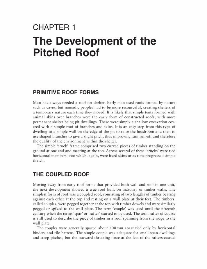
The couples were generally spaced about 400 mm apart tied only by horizontal binders and tile battens. The simple couple was adequate for small span dwellings and steep pitches, but the outward thrusting force at the feet of the rafters caused
2 Roof Construction and Loft Conversion
stability problems with the walls, and excessively long rafters sagged in the middle under the weight of the roof covering. The illustration in Fig. 1.1 shows the required shape in solid line and the defl ected shape in dotted line.
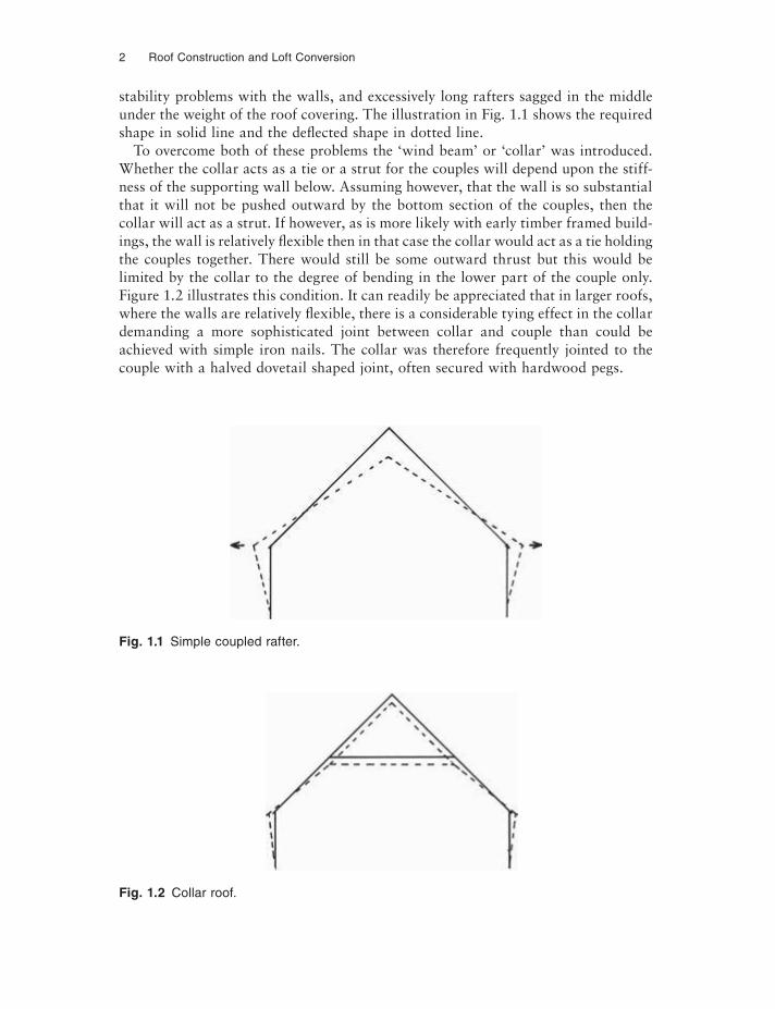
To overcome both of these problems the ‘wind beam’ or ‘collar’ was introduced. Whether the collar acts as a tie or a strut for the couples will depend upon the stiff-ness of the supporting wall below. Assuming however, that the wall is so substantial that it will not be pushed outward by the bottom section of the couples, then the collar will act as a strut. If however, as is more likely with early timber framed build-ings, the wall is relatively flexible then in that case the collar would act as a tie holding the couples together. There would still be some outward thrust but this would be limited by the collar to the degree of bending in the lower part of the couple only. Figure 1.2 illustrates this condition. It can readily be appreciated that in larger roofs, where the walls are relatively flexible, there is a considerable tying effect in the collar demanding a more sophisticated joint between collar and couple than could be achieved with simple iron nails. The collar was therefore frequently jointed to the couple with a halved dovetail shaped joint, often secured with hardwood pegs.
Fig. 1.1 Simple coupled rafter.
Fig. 1.2 Collar roof.
The Development of the Pitched Roof 3
STABILITY
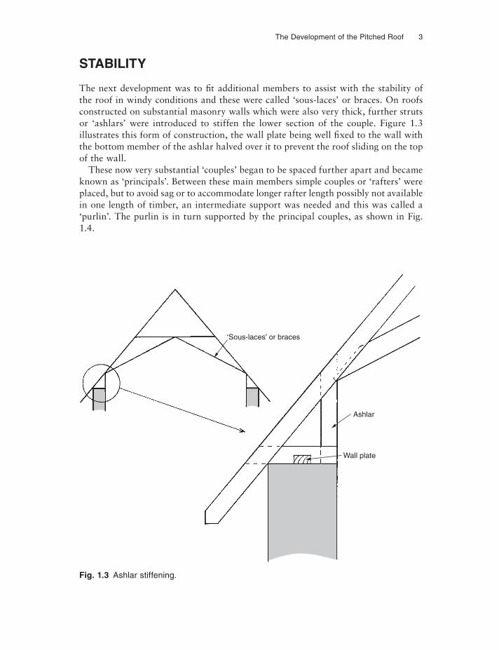
The next development was to fi t additional members to assist with the stability of the roof in windy conditions and these were called ‘sous-laces’ or braces. On roofs constructed on substantial masonry walls which were also very thick, further struts or ‘ashlars’ were introduced to stiffen the lower section of the couple. Figure 1.3 illustrates this form of construction, the wall plate being well fixed to the wall with the bottom member of the ashlar halved over it to prevent the roof sliding on the top of the wall.
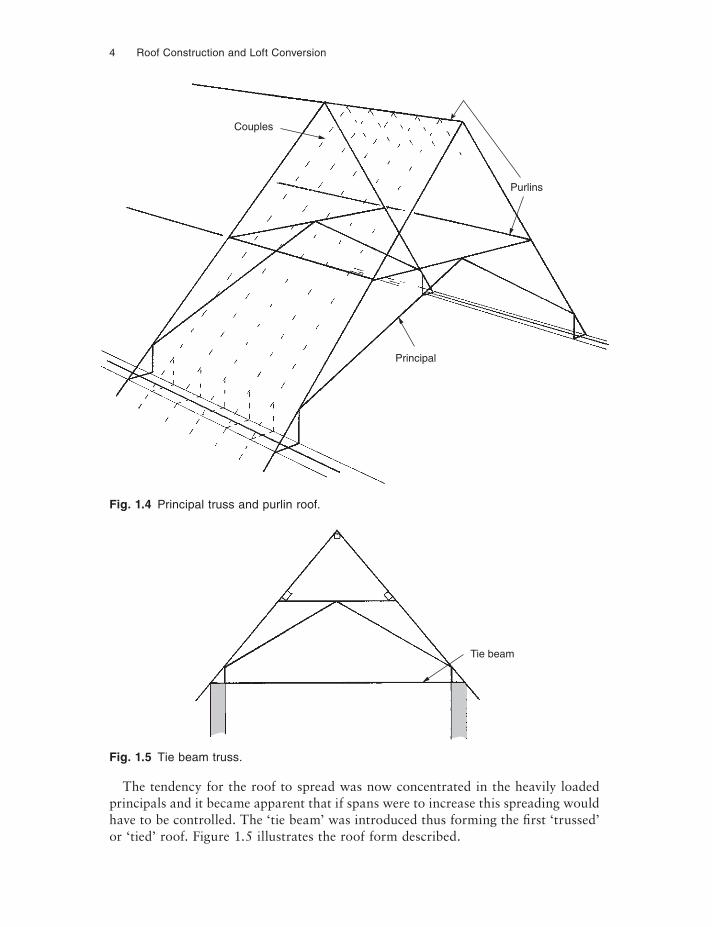
These now very substantial ‘couples’ began to be spaced further apart and became known as ‘principals’. Between these main members simple couples or ‘rafters’ were placed, but to avoid sag or to accommodate longer rafter length possibly not available in one length of timber, an intermediate support was needed and this was called a ‘purlin’. The purlin is in turn supported by the principal couples, as shown in Fig. 1.4.
Fig. 1.3 Ashlar stiffening.
‘Sous-laces’ or braces
Ashlar
Wall plate
4 Roof Construction and Loft Conversion
The tendency for the roof to spread was now concentrated in the heavily loaded principals and it became apparent that if spans were to increase this spreading would have to be controlled. The ‘tie beam’ was introduced thus forming the first ‘trussed’ or ‘tied’ roof. Figure 1.5 illustrates the roof form described.
Fig. 1.4 Principal truss and purlin roof.
Fig. 1.5 Tie beam truss.
Couples
Purlins
Principal
Tie beam
The Development of the Pitched Roof 5
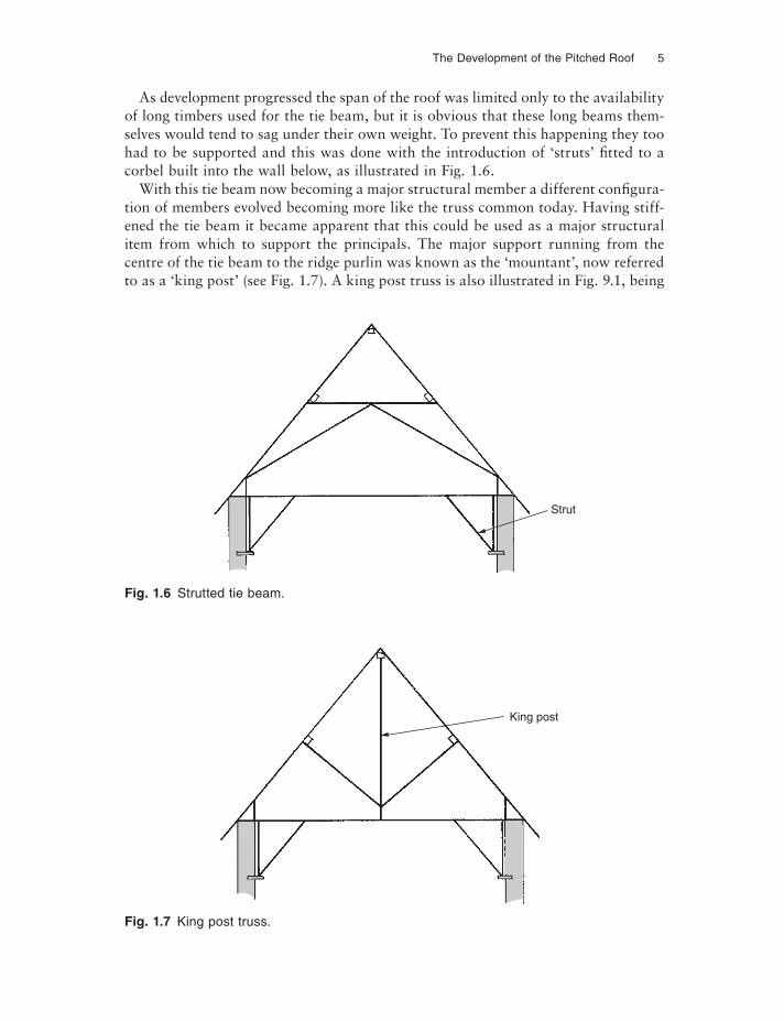
As development progressed the span of the roof was limited only to the availability of long timbers used for the tie beam, but it is obvious that these long beams them-selves would tend to sag under their own weight. To prevent this happening they too had to be supported and this was done with the introduction of ‘struts’ fitted to a corbel built into the wall below, as illustrated in Fig. 1.6.
With this tie beam now becoming a major structural member a different configura-tion of members evolved becoming more like the truss common today. Having stiff-ened the tie beam it became apparent that this could be used as a major structural item from which to support the principals. The major support running from the centre of the tie beam to the ridge purlin was known as the ‘mountant’, now referred to as a ‘king post’ (see Fig. 1.7). A king post truss is also illustrated in Fig. 9.1, being
Fig. 1.6 Strutted tie beam.
Fig. 1.7 King post truss.
Strut
King post
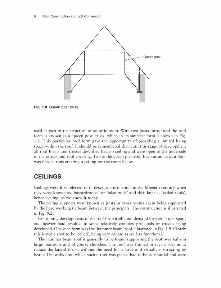
6 Roof Construction and Loft Conversion
used as part of the structure of an attic room. With two posts introduced the roof form is known as a ‘queen post’ truss, which in its simplest form is shown in Fig. 1.8. This particular roof form gave the opportunity of providing a limited living space within the roof. It should be remembered that until this stage of development all roof forms and trusses described had no ceiling and were open to the underside of the rafters and roof covering. To use the queen post roof form as an attic, a floor was needed thus creating a ceiling for the room below.
CEILINGS
Ceilings were fi rst referred to in descriptions of roofs in the fifteenth century when they were known as ‘bastardroofes’ or ‘false roofs’ and then later as ‘ceiled roofs’, hence ‘ceiling’ as we know it today.
The ceiling supports were known as joists or cross beams again being supported by the hard working tie beam between the principals. The construction is illustrated in Fig. 9.2.
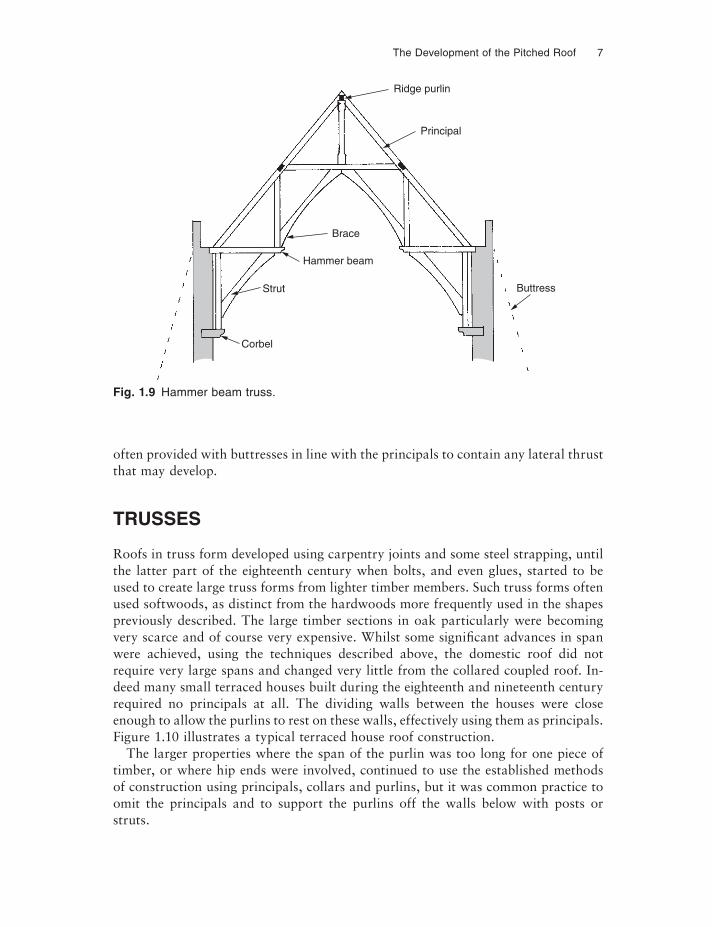
Continuing developments of the roof form itself, and demand for even larger spans and heavier load resulted in some relatively complex principals or trusses being developed. One such form was the ‘hammer beam’ roof, illustrated in Fig. 1.9. Clearly this is not a roof to be ‘ceiled’, being very ornate as well as functional.
The hammer beam roof is generally to be found supporting the roof over halls in large mansions and of course churches. The roof was framed in such a way as to reduce the lateral thrust without the need for a large and visually obstructing tie beam. The walls onto which such a roof was placed had to be substantial and were
Fig. 1.8 Queen post truss.
Queen post
The Development of the Pitched Roof 7
often provided with buttresses in line with the principals to contain any lateral thrust that may develop.
TRUSSES
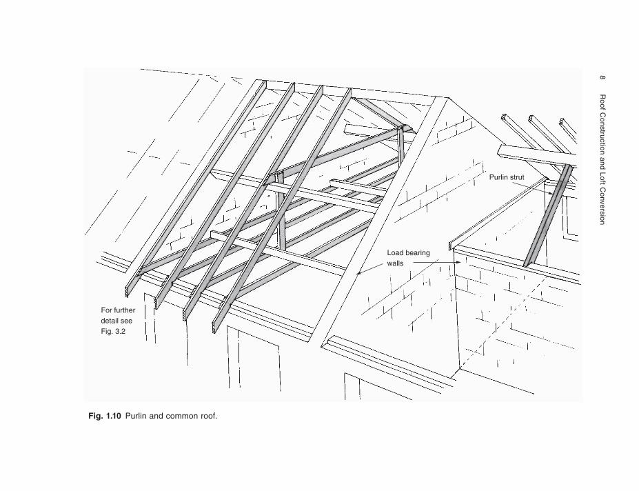
Roofs in truss form developed using carpentry joints and some steel strapping, until the latter part of the eighteenth century when bolts, and even glues, started to be used to create large truss forms from lighter timber members. Such truss forms often used softwoods, as distinct from the hardwoods more frequently used in the shapes previously described. The large timber sections in oak particularly were becoming very scarce and of course very expensive. Whilst some significant advances in span were achieved, using the techniques described above, the domestic roof did not require very large spans and changed very little from the collared coupled roof. In-deed many small terraced houses built during the eighteenth and nineteenth century required no principals at all. The dividing walls between the houses were close enough to allow the purlins to rest on these walls, effectively using them as principals. Figure 1.10 illustrates a typical terraced house roof construction.
The larger properties where the span of the purlin was too long for one piece of timber, or where hip ends were involved, continued to use the established methods of construction using principals, collars and purlins, but it was common practice to omit the principals and to support the purlins off the walls below with posts or struts.
Fig. 1.9 Hammer beam truss.
Ridge purlin
Principal
Brace
Hammer beam
Strut
Corbel
Buttress
8
Roof C
onstruction and Loft Conversion
Fig. 1.10 Purlin and common roof.
For furtherdetail seeFig. 3.2
Load bearingwalls
Purlin strut
The Development of the Pitched Roof 9
DESIGN FOR ECONOMY
In 1934 the Timber Development Association (TDA) was formed, now known as TRADA (Timber Research and Development Association). The Association took up the work already being done at that time by the Royal Aircraft Establishment and progressed work on timber technology alongside the Forest Product Research Laboratories. Although the Royal Aircraft Establishment may sound a strange body to be interested in timber, it must be remembered that many aircraft of that era, and some notable ones after such as the Mosquito, used highly stressed timber structures for the fuselage and wings. Some aircraft hangars were of timber construc-tion and utilised record breaking large span small timber section trusses with bolted joints.
After the Second World War shortages of materials resulted in a licence being required for all new building works, making economy in use of paramount impor-tance. Imported materials such as timber were very much at a premium and TDA was given the task to find ways of economising on the country’s use of timber. Quite correctly they identifi ed the roof structures of buildings as a high volume user of timber and developed a design for a domestic roof using principal trusses constructed of small timber sections connected with bolts and metal connector plates. The roof used purlins and common rafters similar to the systems previously discussed. These trusses became known as ‘TDA’ trusses, and with some minor modifications are still in use today. It appears that some of these designs were available shortly after the Second World War but were first published as a set of standard design sheets around 1950.
The designs were based on existing truss shapes but were not engineered in the sense that structural calculations were prepared for each design. Load testing on full size examples of the truss was used to prove their adequacy and from these tests other designs developed.
STANDARD DESIGN ROOFS
The first designs produced were known as ‘A’ and ‘B’ types, dealing with 40° and 35° pitches respectively. They covered spans up to 30 ft (9 m).
House design fashion changed during the later 1950s and early 1960s, demanding lower roof pitches. 1960 saw the introduction of the TDA type ‘C’ range for pitches between 22° and 30°. Spans were also increased up to 32 ft (10.8 m). Around 1965 the types ‘D’, ‘E’ and ‘F’ ranges were published; these later designs using a slightly different truss member layout went down to 15° pitch and up to 40 ft (12 m) span. Further designs used trusses spaced at 6 ft (1.8 m) centres and had some degree of pitch and span flexibility within specifi ed limitations.
A range of designs for trussed rafters (i.e. each couple tied together at ceiling level) was produced also using bolt and connector joints, but these were designed only to carry felt roof coverings and did not prove as popular as the principal truss designs.
10 Roof Construction and Loft Conversion
Industrial roofs were not neglected, with principal truss designs using the bolt and connector joint techniques for pitches of 22.5° spacing between 11 and 14 ft (3.35–4.25 m) and up to 66 ft (20.1 m) span.
Whilst roofs are still constructed using these techniques, the TDA designs are no longer available from TRADA.
BOLT AND CONNECTOR JOINTS
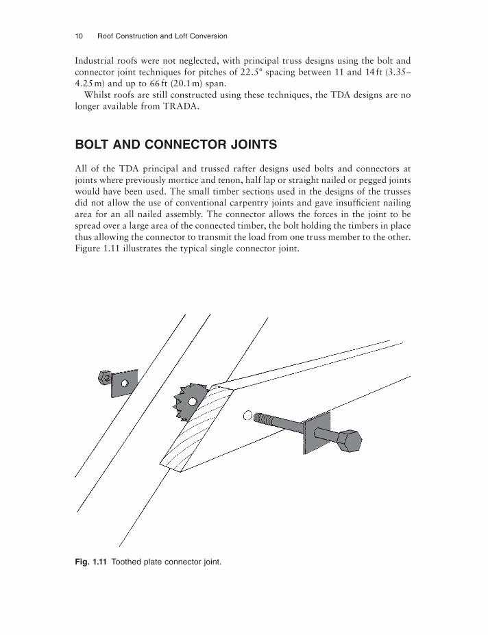
All of the TDA principal and trussed rafter designs used bolts and connectors at joints where previously mortice and tenon, half lap or straight nailed or pegged joints would have been used. The small timber sections used in the designs of the trusses did not allow the use of conventional carpentry joints and gave insuffi cient nailing area for an all nailed assembly. The connector allows the forces in the joint to be spread over a large area of the connected timber, the bolt holding the timbers in place thus allowing the connector to transmit the load from one truss member to the other. Figure 1.11 illustrates the typical single connector joint.
Fig. 1.11 Toothed plate connector joint.
The Development of the Pitched Roof 11
TRUSSED RAFTERS
In the early 1960s the punched metal connector plate was introduced into the UK from the USA and was to revolutionise the construction of domestic roofs even more than the TDA truss designs described. There are now four main plate manufacturers in the UK, the fi rst in 1967 being Gang-Nail whose name has come to be used to describe all punched metal connector trusses, in the same way that ‘Hoover’ seems to describe a vacuum cleaner.
Trussed rafters are generally prefabricated in a factory and transported to site, although with certain types of plate, fabrication can take place on site. In the case of metal plates, the manufacturer sells plates backed up to varying degrees with de-sign aids to approved manufacturers, many of whom are also timber merchants. The timber used is both graded for strength and machined on all surfaces to give accuracy to the fi nished product. Trussed rafters can also be assembled using plywood gussets, the plywood being either nailed to a defined pattern or nailed and glued to the truss members to form the joint. Ply gusseted trusses are not as popular as metal plated trusses, but do offer a method of manufacture not requiring specialist equipment. Similarly the galvanised steel plates punched with a pattern of holes to receive nails can also be used to form truss joints and these too can be fabricated on site.
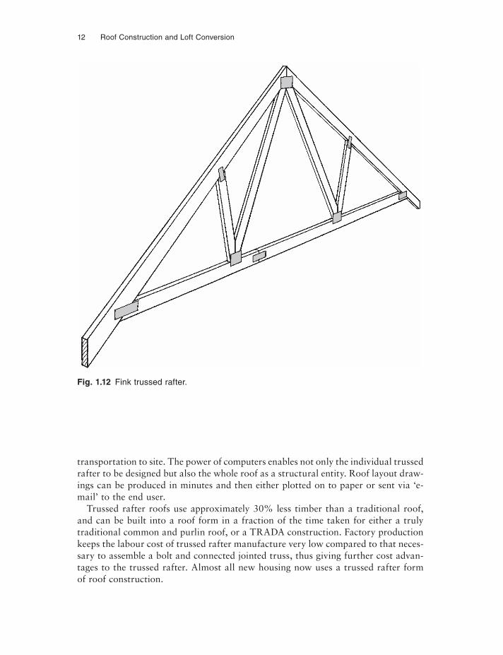
The punched metal nail plates used in factory trussed rafter production are mechanically pressed into the timbers on both sides of each joint to form a trussed rafter. This trussed rafter is then placed on the roof at approximately 600 mm centres taking the place of the common rafter. Hence its term ‘trussed rafter’, as distinct from the TRADA type principal truss, although it will be seen later in Chapter 6 that trussed rafters themselves can be used to form principal or girder trusses. A typical Fink trussed rafter is illustrated in Fig. 1.12.
COST ADVANTAGES
Trussed rafters are designed to carry simply the direct load imposed upon them. It is assumed that they are to be kept upright by other members, these members being the binders and diagonal bracing and even the tile batten vital to the overall stability of the roof. Whilst most trussed rafters are used for roofs of housing, their use is increasing for roofs of public buildings, commercial buildings and to a lesser extent for industrial and agricultural buildings. Clear spans in excess of 30 m can be achieved with lightweight roof coverings.
When first introduced into the UK, the designs were limited to those contained in standard design manuals, thus the duo pitch and mono pitched roofs were common but more complex roofs needed individual designs prepared. The advent of the com-puter both speeded up and dramatically reduced the cost of the design process, and this has been further advanced by the use of microcomputers installed in all trussed rafter manufacturers’ offices. There are now almost no limitations to the possible shape of trussed rafters, except those imposed by the practicality of production and
12 Roof Construction and Loft Conversion
transportation to site. The power of computers enables not only the individual trussed rafter to be designed but also the whole roof as a structural entity. Roof layout draw-ings can be produced in minutes and then either plotted on to paper or sent via ‘e-mail’ to the end user.
Trussed rafter roofs use approximately 30% less timber than a traditional roof, and can be built into a roof form in a fraction of the time taken for either a truly traditional common and purlin roof, or a TRADA construction. Factory production keeps the labour cost of trussed rafter manufacture very low compared to that neces-sary to assemble a bolt and connected jointed truss, thus giving further cost advan-tages to the trussed rafter. Almost all new housing now uses a trussed rafter form of roof construction.
Fig. 1.12 Fink trussed rafter.
The Development of the Pitched Roof 13
LEGISLATION
Having looked at the development of the roof form, we must take account of the legislation controlling building construction in the UK. Before the twentieth century no controls existed, and it was not until the introduction of the model byelaws by each local authority area that some degree of control was placed upon the design of buildings.
The Building Regulations as we now know them fi rst appeared in 1965, and have been amended and re-issued on several occasions since that date. Subsequent amend-ments have dealt with such roof related matters as the restraint of gable and walls, thermal insulation and roof void ventilation. The first major change to the Building Regulations occurred in 1985 and took the form of a two-part publication, the first part setting the standards to be achieved and the second, for approved documents, laying down approved methods of achieving them. The fourth edition of this book has been produced in the light of the latest edition of the Building Regulations which came into force in 2000, including the recent amendments. These regulations lay down the legal requirements for building and concern themselves with health and safety aspects and not the aesthetic aspects of the structure. The latter, of course, is controlled by the local planning authorities.
The National House-Building Council (known as NHBC) has its own set of stan-dards, which although incorporating the Building Regulations requirements, look beyond the health and safety aspects and seek to set minimum standards for quality control and such items as heating, electrical power sockets, and the general fi nish given to the buildings. Formed in 1936 it was not until the mid-1960s that the council began to have infl uence on the vast majority of house builders in the UK.
Concerned by the so-called ‘jerry builders’ after the Second World War, the build-ing societies needed some method of ensuring that the homes on which they had granted mortgages were of an adequate standard to protect their investment. These societies therefore demanded that house builders building and wishing to sell homes on which the societies were granting mortgages must belong to the NHBC and submit themselves to their inspections. Having achieved full compliance with the NHBC requirements and of course the Building Regulations, the mortgage would be granted. Consequently most newly built homes until now have had to be inspected by the local authority as well as the NHBC, although this is likely to change in the near future, and only the inspectorate of the NHBC will be involved. An alternative to NHBC for mortgage purposes in most instances, is that the house should be inspected by a registered architect, and this seems to be the only way that a non-registered house builder can build and sell a new home under a mortgage agreement.
The Building Regulations and NHBC standards in turn refer to various British Standards and it is intended here only to deal with those British Standards concerned with timber in roof structures.
Code of Practice 112 started life in 1952, and was amended in 1967 when the principle of allocating grade stresses to timber was introduced. 1971 saw further
14 Roof Construction and Loft Conversion
changes to the code of practice, then issued with stresses and timber sizes in metric units. This code became British Standard 5268 which itself was split into many parts: Part 2 deals with the general principles of timber structural design. Part 2: 1996 simplifi ed the hitherto relatively complex subject of stress grading by grouping tim-bers into strength classes ranging from C16 for softwoods to D70 for hardwoods. However, the Building Regulations approved document table still referred to the earlier issue of BS 5268: Part 2: 1991, and remained based on SC3 and SC4 grades.
The current standard recognises a special grade for the use in punched metal nail plated trussed rafters known as TR6. BS 5268: Part 3: 2002 deals specifically with the design and fabrication of trussed rafter roof construction. BS 6399: Part 3: 1998 is the code of practice for the loads imposed on roofs, dealing with such aspects as dead and live loads as well as snow loading. BS 5250 concerns itself with the roof void ventilation and was last reviewed in 1995. BS 5534: Part 1: 1997 deals with the design of slating and tiling with the recommendations for workmanship for these roof coverings being given in BS 8000: Part 6.
British Standard 4471: 1987, Sizes for sawn and processed softwood has now been withdrawn and replaced by an English language version of the European code EN 313, known as BS EN 1313/1: Part 1: 1997, Softwood sawn timber.The standard sets out standard sizes and processing tolerances, whilst BS 4978, revised in 1996, deals with the stresses allocated to structural timbers. This edition has been revised to take account of the publication of the relevant European Standards:
(1) Changes have been made to the visual grading section in accordance with BSEN 518 structural timber – grading – requirements for visual standards.
(2) Machine strength grading is now specifi ed in BSEN 519 structural timber – grad-ing – requirements for machine strength graded timber and grading machines. The sections concerning machine strength grading have been deleted and the title has been changed.
(3) The sections concerning visual strength grades for laminations have been deleted.
(4) BS EN338: 2003, structural timber. Strength classes.
This British Standard specifies the means of assessing the quality of softwoods for which grade stresses are given in BS 5268: Part 2. This document is recommended for those wishing to have some insight into the visual appearance of the type of tim-ber that they can expect with the various stress gradings. Such factors as knots, fis-sures, bow, spring and twist are dealt with, giving limiting factors.
The above deals with timber from European countries. Timber from Canada and the USA is covered by their own standards which are recognised in the UK for visu-ally graded timber. These are NLGA, Canada, national grading rules for dimension lumber, and NGRDL, USA, national grading rules for softwood dimension lumber. There is also a machine grade standard known as NAMSR set by the North American exports standard. This was introduced to give more precise selection of strength potential, thus increasing the economic use of this natural resource.
The Development of the Pitched Roof 15
All structural timber used in dwellings must now be graded into stress limiting classes and marked with the grades. The mark must show not only the grade, but the grader and the grading station, the British Standard number and the species group. Alternatively of course it can be marked with the approved Canadian and American grading stamps. Grading can be carried out either visually by qualifi ed visual graders, or by licensed stress grading machines operated by trained staff.
Earlier standards classifi ed timbers within a single species and were developed from an assessment of the timber’s strength compared to that of a defect free sample, thus the old grades of 40, 50, 65 and 75 represented the percentage strength of the sample compared to the defect free sample. Thus with different species offering different strength properties it can be seen that a weak timber (say Balsa wood), at 75 grade would be much weaker than British pine at 75 grade. The strength classes simplify this by classifying by strength regardless of species, thus a piece of C14 balsa (not that it actually exists), would have the same structural ability as a piece of C14 British pine. This of course simplifies design unless visual appearance is of impor-tance on exposed structural feature members of a roof form, in which case the designer should refer to BS 4978 to gauge for himself the visual defects likely to be allowable under the strength class selected by structural analysis.
As old strength classes are still allowed by the current Building Regulations 2000, the comparison table below may be of interest and assistance.
• SC3 now C16;• SC4 now C24;• SC5 now C27;• Softwood grades now range as follows: C14, C16, C18, C22, C24, C27 (and TR6
for trussed rafters), C35 and C40;• Hardwood grades are now: D30, D35, D40, D50, D60 and D70. Most roof struc-
tural softwood timber will fall in the range C16/C24 plus of course TR26 for trussed rafters.
The second edition of this book at this juncture mentioned the new European Stan-dards. It is true to say that some have been introduced, such as Euro code 5 and harmonisation has continued between British and European codes, hence the BSEN prefix now being used. However, at the house extension, alteration and repair end of the market, the SC3–SC5 strength classes still apply and are commonly in use.
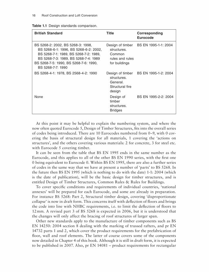
Proposed modifications to design standardsAt the time of preparation of this fourth edition, the standards governing the design of timber structures, the stress classification of timber used and the quality control of timber and timber components are in a state of fl ux. This is caused mainly by harmonisation with the European codes. Whilst many of these European codes already exist, they do not become mandatory until 2010. Consequently, British Standards continue to be used but under revision to progressively align them with Eurocodes, which by 2010 will themselves have been subjected to further modifi -cations. The comparisons in Table 1.1 give an indication of these changing codes.
16 Roof Construction and Loft Conversion
At this point it may be helpful to explain the numbering system, and where the now often quoted Eurocode 5, Design of Timber Structures, fi ts into the overall series of codes being introduced. There are 10 Eurocodes numbered from 0–9, with 0 cov-ering the basis of structural design for all materials, 1 covering the ‘actions on structures’, and the others covering various materials: 2 for concrete, 3 for steel etc. with Eurocode 5 covering timber.
It can be seen from the table that BS EN 1995 ends in the same number as the Eurocode, and this applies to all of the other BS EN 1990 series, with the first one0 being equivalent to Eurocode 0. Within BS EN 1995, there are also a further series of codes in the same way that we have at present a number of ‘parts’ to BS 5268. In the future then BS EN 1995 (which is nothing to do with the date) 1-1: 2004 (which is the date of publication), will be the basic design for timber structures, and is entitled Design of Timber Structures, Common Rules & Rules for Buildings.
To cover specific conditions and requirements of individual countries, ‘national annexes’ will be prepared for each Eurocode, and some are already in preparation. For instance BS 5268: Part 2, Structural timber design, covering ‘disproportionate collapse’ is now in draft form. This concerns itself with deflection of fl oors and brings the code into line with NHBC requirements, i.e. to limit the deflection of floors to 12 mm. A revised part 3 of BS 5268 is expected in 2006, but it is understood that the changes will only affect the bracing of roof structures of larger span.
Other new standards apply to the manufacture of timber components such as BS EN 14250: 2004 section 8 dealing with the marking of trussed rafters, and pr EN 14732 parts 1 and 2, which cover the product requirements for the prefabrication of floor, wall and roof elements. The latter of course covers some of the components now detailed in Chapter 4 of this book. Although it is still in draft form, it is expected to be published in 2007. Also, pr EN 14081 – product requirements for rectangular
Table 1.1 Design standards comparison.
British Standard Title Corresponding Eurocode
BS 5268-2: 2002, BS 5268-3: 1998, Design of timber BS EN 1995-1-1: 2004BS 5268-6-1: 1996, BS 5268-6-2: 2002, structures.BS 5268-7-1: 1989, BS 5268-7-2: 1989, CommonBS 5268-7-3: 1989, BS 5268-7-4: 1989 rules and rules
BS 5268-7-5: 1990, BS 5268-7-6: 1990, for buildingsBS 5268-7-7: 1990
BS 5268-4-1: 1978, BS 2568-4-2: 1990 Design of timber BS EN 1995-1-2: 2004 structures. General. Structural fi re design
None Design of BS EN 1995-2-2: 2004 timber structures. Bridges
The Development of the Pitched Roof 17
solid timber. By the time this book is published, it is likely to be in circulation. This will pave the way for CE marking of timber. Since CE marking is not mandatory in the UK this brings about the spectre of seeing timber in the future without a third-party quality assurance (QA) being exercised on its grading. BS 5268-2 currently mandates the need for a third-party QA on timber grading for all its designs, but Eurocode (EC) 5 contains no such requirement, assuming that all countries will re-quire CE marking anyway. Efforts are now being directed to close this potential loop-hole for the timber designs to EC 5, by inserting a requirement in the UK Build-ing Regulations that in the specific case of structural timber grading, third-party QA is necessary. As a result of efforts by TRA (Trussed Rafter Association), machine grading settings for TR26 ERW (albeit not identical to those we have been using up until now) will be inserted in part 4 of the standard. The results of yield tests on the timber are now eagerly awaited. These TR26 settings will sit alongside other settings in part 4 for C24, C27, C30 etc. and will now be used universally across Europe.
As can be seen from the short discussion above, timber grading is a detailed sci-entific subject well outside the scope of this book. The book is concerned with the constructional design of the roof, rather than the calculation of structural design and specification. The reader is directed to those British Standards referred to above, the many publications available from TRADA, and the Timber Designers’ Manual by Baird and Ozelton.
Roof development will undoubtedly continue. The timber sizes used in modern trussed roof construction really constitute the practical minimum possible. Structur-ally it may be feasible to reduce those sizes, but for reasons of achieving adequate fixings for ceiling boards and tile battens, the timber sizes cannot be reduced. It is therefore difficult to see beyond the trussed rafter, but its method of construction into the completed roof form may change.
Although the labour involved in erecting a trussed rafter roof is relatively small, access at roof plate level and within the roof structure whilst under construction is not good. As will be seen in Chapter 6, the British Standard requires a considerable amount of additional bracing to be installed within the roof, thus increasing the la-bour involved and the hazards of gaining access within the roof void. For this reason a practice relatively common with the large panel timber framed housing systems may become increasingly popular. This is to construct the roof including the wall plate at ground level, complete with all binders, bracing, ties, tank platform, tank, felt battens, barge and fascias where appropriate. This whole, relatively light assembly can then be craned on to the shell and fixed in position. It is not suggested that this is a cost effective method for very small building sites, but on the larger estates, where continuity of house building is achieved, it has many advantages, not the least of which is the safety of the workman concerned.
Continued development over the past few years has seen the growth in roofs con-structed using prefabricated panels, some pre-insulated and weatherproofed, and some, which are referred to as ‘cassettes’, also include a prefixed ceiling. These methods of construction are ideally suited to quickly constructed weatherproof attics, allowing internal works to continue whilst the final felt (if necessary), battens and tiles are applied. Not all of these systems require crane erection. These proprietary systems are described and illustrated in more detail in the new Chapter 4 of this fourth edition.
CHAPTER 2
Roof Shapes and Terminology
A B
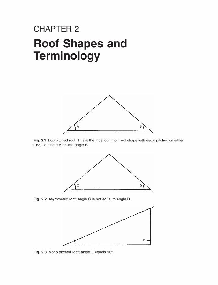
Fig. 2.1 Duo pitched roof. This is the most common roof shape with equal pitches on either side, i.e. angle A equals angle B.
C D
Fig. 2.2 Asymmetric roof; angle C is not equal to angle D.
E
Fig. 2.3 Mono pitched roof; angle E equals 90°.

Roof Shapes and Terminology 19
G
F
S/4S/4
S/4S/4
S/3S/3
S/3
S
S/6S/6
S/6S/6
S/6S/6
S/3S/3S
S/3
Fig. 2.4 Truncated duo pitched roof; angle F equals angle G. This truss form is often intro-duced into domestic housing in conjunction with the conventional duo pitched roof to form an interesting roof line.
Fig. 2.5 Fink truss shape. This is the most common trussed rafter form used on spans of up to 8 to 9 m.
Fig. 2.6 Fan truss shape. This is used on larger spans and is a common trussed rafter form.
20 Roof Construction and Loft Conversion
S/6S/6
S/6S/6
S/6S/6
S/5S/5
S/5
S
S/5 5S/
S/4S/4
S/4S/4
S
S/4S/4
S/4S/4
S
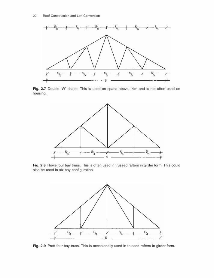
Fig. 2.7 Double ‘W’ shape. This is used on spans above 14 m and is not often used on housing.
Fig. 2.8 Howe four bay truss. This is often used in trussed rafters in girder form. This could also be used in six bay confi guration.
Fig. 2.9 Pratt four bay truss. This is occasionally used in trussed rafters in girder form.
Roof Shapes and Terminology 21
h
w
S/2S/2
S
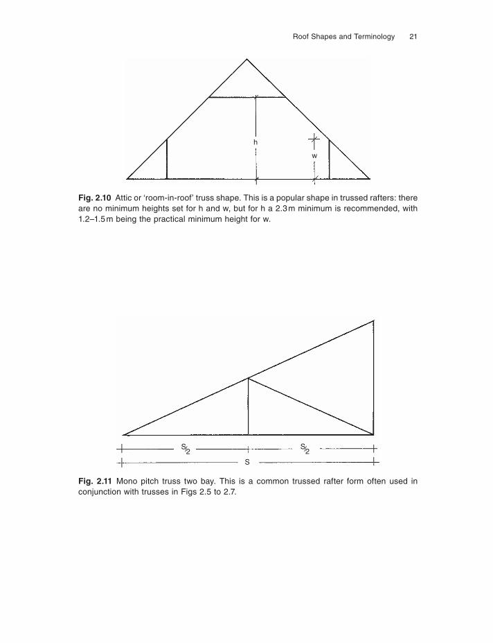
Fig. 2.10 Attic or ‘room-in-roof’ truss shape. This is a popular shape in trussed rafters: there are no minimum heights set for h and w, but for h a 2.3 m minimum is recommended, with 1.2–1.5 m being the practical minimum height for w.
Fig. 2.11 Mono pitch truss two bay. This is a common trussed rafter form often used in conjunction with trusses in Figs 2.5 to 2.7.
22 Roof Construction and Loft Conversion
S/6S/6
S/6 6 6S/
S
S/6S/
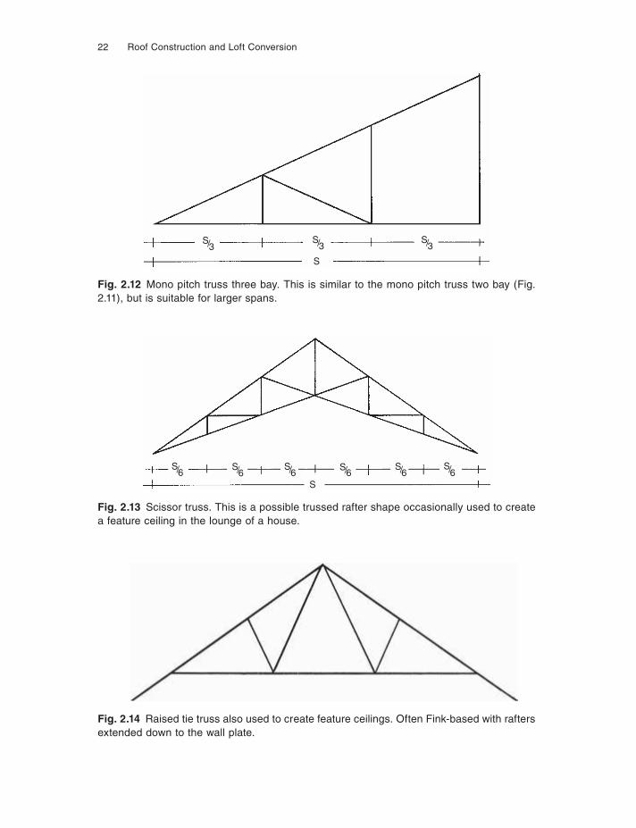
Fig. 2.13 Scissor truss. This is a possible trussed rafter shape occasionally used to create a feature ceiling in the lounge of a house.
Fig. 2.14 Raised tie truss also used to create feature ceilings. Often Fink-based with rafters extended down to the wall plate.
S/3S/3
S/3
S
Fig. 2.12 Mono pitch truss three bay. This is similar to the mono pitch truss two bay (Fig. 2.11), but is suitable for larger spans.
Roof Shapes and Terminology 23
TERMINOLOGY
Chapter 1 has given the history and derivation of some of the names given to roof structure members. The list below, although not exhaustive, describes the terms used on domestic roof structures.
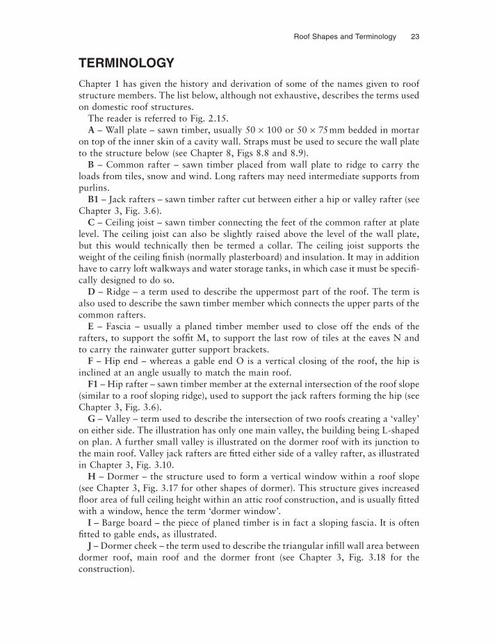
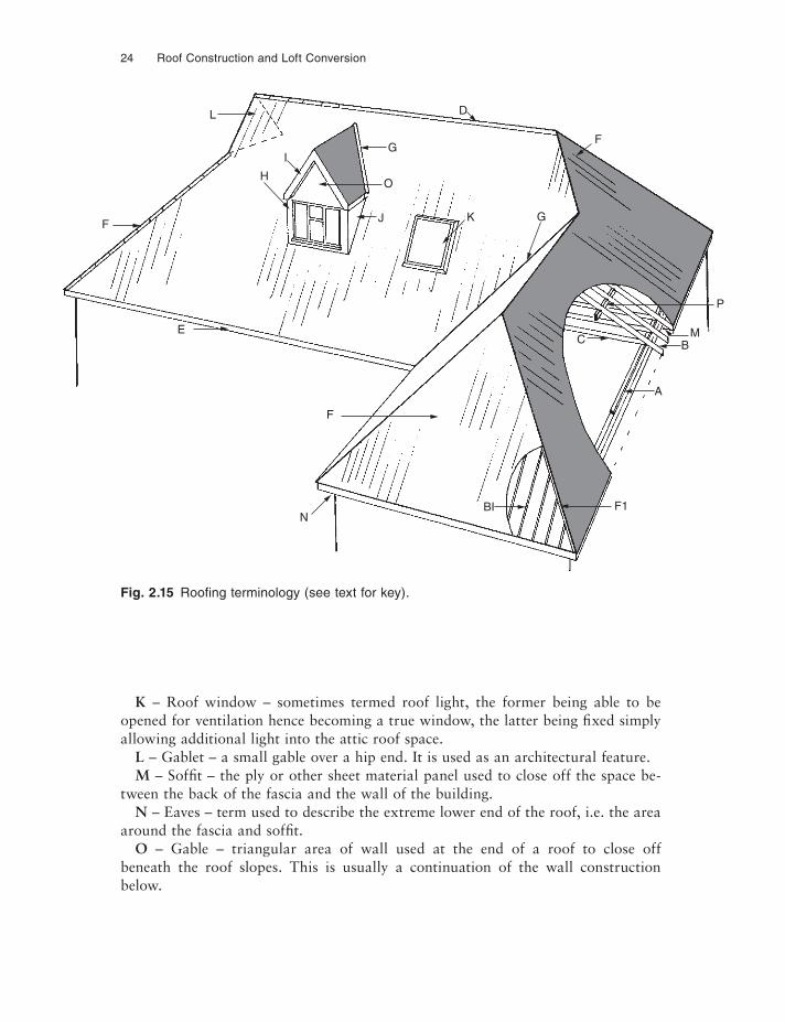
The reader is referred to Fig. 2.15.A – Wall plate – sawn timber, usually 50 × 100 or 50 × 75 mm bedded in mortar
on top of the inner skin of a cavity wall. Straps must be used to secure the wall plate to the structure below (see Chapter 8, Figs 8.8 and 8.9).
B – Common rafter – sawn timber placed from wall plate to ridge to carry the loads from tiles, snow and wind. Long rafters may need intermediate supports from purlins.
B1 – Jack rafters – sawn timber rafter cut between either a hip or valley rafter (see Chapter 3, Fig. 3.6).
C – Ceiling joist – sawn timber connecting the feet of the common rafter at plate level. The ceiling joist can also be slightly raised above the level of the wall plate, but this would technically then be termed a collar. The ceiling joist supports the weight of the ceiling fi nish (normally plasterboard) and insulation. It may in addition have to carry loft walkways and water storage tanks, in which case it must be specifi -cally designed to do so.
D – Ridge – a term used to describe the uppermost part of the roof. The term is also used to describe the sawn timber member which connects the upper parts of the common rafters.
E – Fascia – usually a planed timber member used to close off the ends of the rafters, to support the soffi t M, to support the last row of tiles at the eaves N and to carry the rainwater gutter support brackets.
F – Hip end – whereas a gable end O is a vertical closing of the roof, the hip is inclined at an angle usually to match the main roof.
F1 – Hip rafter – sawn timber member at the external intersection of the roof slope (similar to a roof sloping ridge), used to support the jack rafters forming the hip (see Chapter 3, Fig. 3.6).
G – Valley – term used to describe the intersection of two roofs creating a ‘valley’ on either side. The illustration has only one main valley, the building being L-shaped on plan. A further small valley is illustrated on the dormer roof with its junction to the main roof. Valley jack rafters are fi tted either side of a valley rafter, as illustrated in Chapter 3, Fig. 3.10.
H – Dormer – the structure used to form a vertical window within a roof slope (see Chapter 3, Fig. 3.17 for other shapes of dormer). This structure gives increased fl oor area of full ceiling height within an attic roof construction, and is usually fitted with a window, hence the term ‘dormer window’.
I – Barge board – the piece of planed timber is in fact a sloping fascia. It is often fi tted to gable ends, as illustrated.
J – Dormer cheek – the term used to describe the triangular infi ll wall area between dormer roof, main roof and the dormer front (see Chapter 3, Fig. 3.18 for the construction).
24 Roof Construction and Loft Conversion
Fig. 2.15 Roofi ng terminology (see text for key).
F
L
H
I
E
F
NBI F1
A
C BM
P
F
GK
D
G
O
J
K – Roof window – sometimes termed roof light, the former being able to be opened for ventilation hence becoming a true window, the latter being fixed simply allowing additional light into the attic roof space.
L – Gablet – a small gable over a hip end. It is used as an architectural feature.M – Soffi t – the ply or other sheet material panel used to close off the space be-
tween the back of the fascia and the wall of the building.N – Eaves – term used to describe the extreme lower end of the roof, i.e. the area
around the fascia and soffit.O – Gable – triangular area of wall used at the end of a roof to close off
beneath the roof slopes. This is usually a continuation of the wall construction below.
Roof Shapes and Terminology 25
P – Purlin – large section sawn solid structural timber, or fabricated beam, used to carry the common rafters on larger roof slopes where the commons are not strong enough or cannot be obtained in one single length, to span between the wall plate and the ridge (see Figs 3.1, 3.4 and 3.5).
CHAPTER 3
The ‘Traditional’ or ‘Cut’ Roof
DESIGN
The traditional or ‘cut’ roof as it has become known is essentially a roof cut and as-sembled on site from individual timber members. It is most frequently a common rafter and purlin roof, the design of which can be prepared from readily available standard span tables for the individual timber members. Hips and valleys are generally constructed to what has become known as ‘good practice’ and are less well documented with span tables and specific design aids. The sizing of these members is often left to the architect or engineer and it is not always necessary to provide calculations to prove their adequacy. The design of all new roof structures in England, Wales and Inner London must of course conform with the latest edition of the Building Regulations. In Scotland the Building Standards (Scotland) regulations apply, and in Northern Ireland the Building Regulations (Northern Ireland).
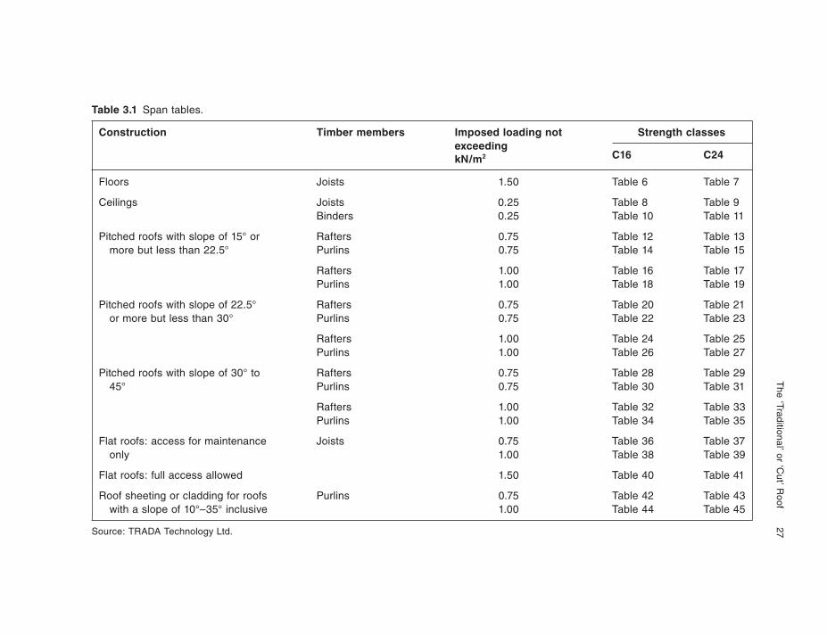
The Building Regulations 2000 set out the statutory standards of construction to be achieved, and whilst the 1991 edition of the regulations contained approved docu-ments, the new ones do not. For guidance on roof design, the Building Regulations refer to a TRADA publication entitled Span Tables for Solid Timber Members in Floors, Ceilings & Roofs (Excluding Trussed Rafter Roofs) For Dwellings. It is their publication reference TRADA technology design aid DA 1/2004. This document covers the design of all members likely to be encountered in a simple roof construc-tion and is an extremely complete guide, giving the background to the designs, listing all current standards relevant to roof member design and to timber grading. A list of the span tables contained in the publication is set out in Table 3.1, and is a repro-duction of Table 5 from that document. It is strongly recommended that anyone who is in any way involved with the study, design, alteration, conversion and repair, or the approval of roof structures should have a copy for reference. Full details of TRADA can be found in the bibliography.
The ‘Traditional’ or
‘Cut’ R
oof
27
Table 3.1 Span tables.
Construction Timber members Imposed loading not Strength classesexceeding
C16 C24
Floors Joists 1.50 Table 6 Table 7
Ceilings Joists 0.25 Table 8 Table 9Binders 0.25 Table 10 Table 11
Pitched roofs with slope of 15° or Rafters 0.75 Table 12 Table 13more but less than 22.5° Purlins 0.75 Table 14 Table 15
Rafters 1.00 Table 16 Table 17Purlins 1.00 Table 18 Table 19
Pitched roofs with slope of 22.5° Rafters 0.75 Table 20 Table 21or more but less than 30° Purlins 0.75 Table 22 Table 23
Rafters 1.00 Table 24 Table 25Purlins 1.00 Table 26 Table 27
Pitched roofs with slope of 30° to Rafters 0.75 Table 28 Table 2945° Purlins 0.75 Table 30 Table 31
Rafters 1.00 Table 32 Table 33Purlins 1.00 Table 34 Table 35
Flat roofs: access for maintenance Joists 0.75 Table 36 Table 37only 1.00 Table 38 Table 39
Flat roofs: full access allowed 1.50 Table 40 Table 41
Roof sheeting or cladding for roofs Purlins 0.75 Table 42 Table 43with a slope of 10°–35° inclusive 1.00 Table 44 Table 45
Source: TRADA Technology Ltd.
kN/m2
28 Roof Construction and Loft Conversion
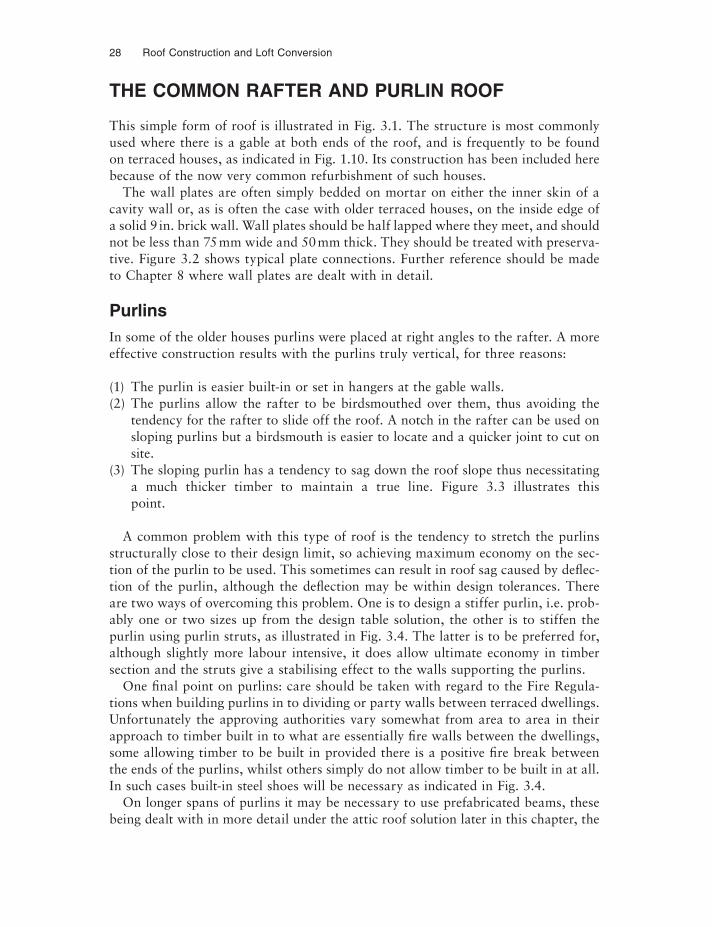
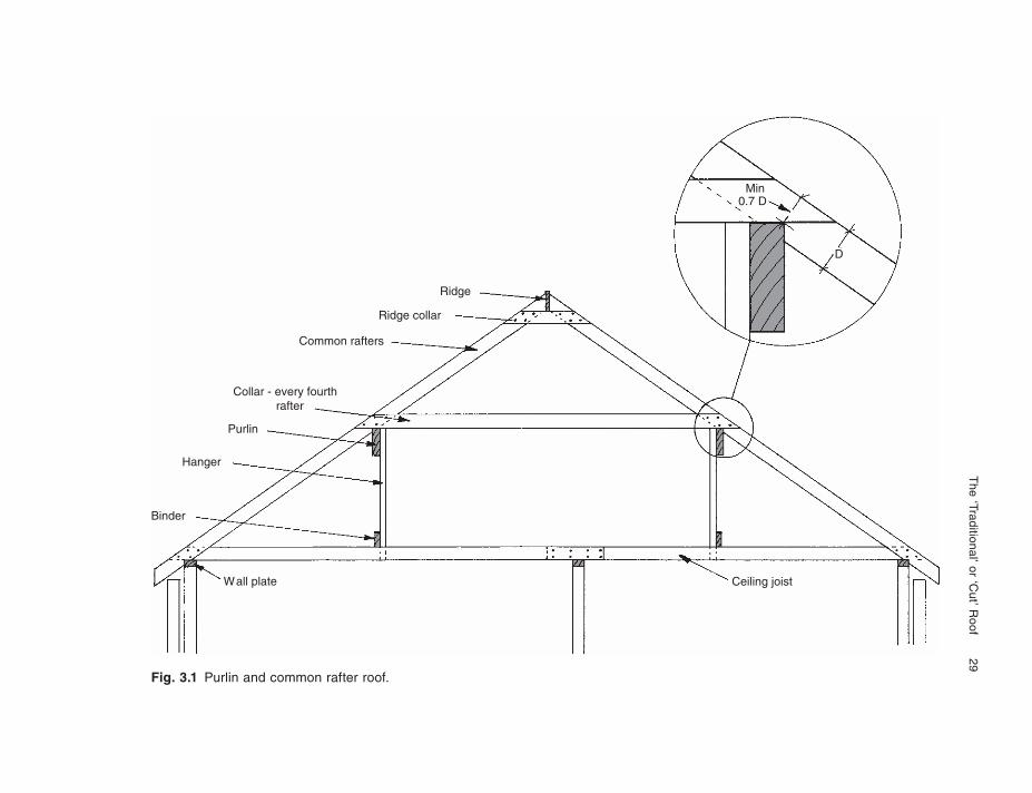
THE COMMON RAFTER AND PURLIN ROOF
This simple form of roof is illustrated in Fig. 3.1. The structure is most commonly used where there is a gable at both ends of the roof, and is frequently to be found on terraced houses, as indicated in Fig. 1.10. Its construction has been included here because of the now very common refurbishment of such houses.
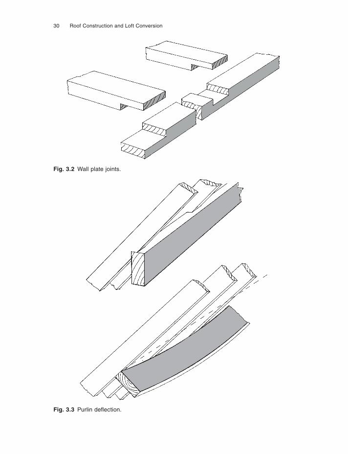
The wall plates are often simply bedded on mortar on either the inner skin of a cavity wall or, as is often the case with older terraced houses, on the inside edge of a solid 9 in. brick wall. Wall plates should be half lapped where they meet, and should not be less than 75 mm wide and 50 mm thick. They should be treated with preserva-tive. Figure 3.2 shows typical plate connections. Further reference should be made to Chapter 8 where wall plates are dealt with in detail.
PurlinsIn some of the older houses purlins were placed at right angles to the rafter. A more effective construction results with the purlins truly vertical, for three reasons:
(1) The purlin is easier built-in or set in hangers at the gable walls.(2) The purlins allow the rafter to be birdsmouthed over them, thus avoiding the
tendency for the rafter to slide off the roof. A notch in the rafter can be used on sloping purlins but a birdsmouth is easier to locate and a quicker joint to cut on site.
(3) The sloping purlin has a tendency to sag down the roof slope thus necessitating a much thicker timber to maintain a true line. Figure 3.3 illustrates this point.
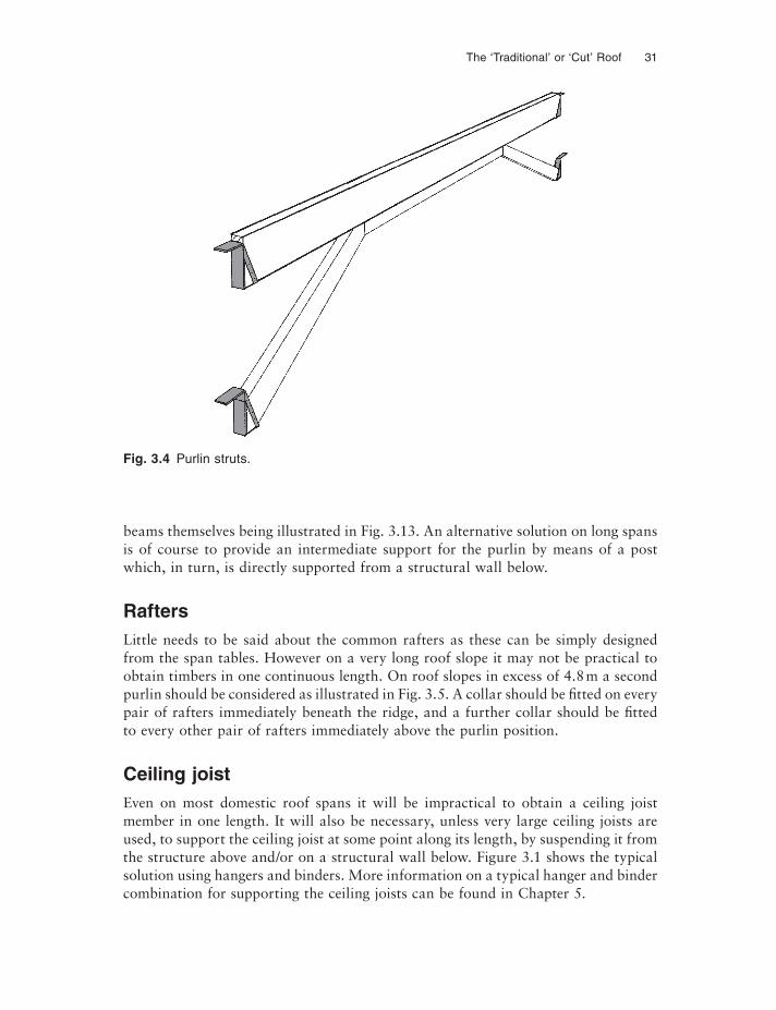
A common problem with this type of roof is the tendency to stretch the purlins structurally close to their design limit, so achieving maximum economy on the sec-tion of the purlin to be used. This sometimes can result in roof sag caused by deflec-tion of the purlin, although the deflection may be within design tolerances. There are two ways of overcoming this problem. One is to design a stiffer purlin, i.e. prob-ably one or two sizes up from the design table solution, the other is to stiffen the purlin using purlin struts, as illustrated in Fig. 3.4. The latter is to be preferred for, although slightly more labour intensive, it does allow ultimate economy in timber section and the struts give a stabilising effect to the walls supporting the purlins.
One final point on purlins: care should be taken with regard to the Fire Regula-tions when building purlins in to dividing or party walls between terraced dwellings. Unfortunately the approving authorities vary somewhat from area to area in their approach to timber built in to what are essentially fire walls between the dwellings, some allowing timber to be built in provided there is a positive fire break between the ends of the purlins, whilst others simply do not allow timber to be built in at all. In such cases built-in steel shoes will be necessary as indicated in Fig. 3.4.
On longer spans of purlins it may be necessary to use prefabricated beams, these being dealt with in more detail under the attic roof solution later in this chapter, the
The ‘Traditional’ or
‘Cut’ R
oof
29
Fig. 3.1 Purlin and common rafter roof.
Min0.7 D
Ridge
Ridge collar
Common rafters
Collar - every fourthrafter
Purlin
Hanger
Binder
Wall plate Ceiling joist
D
30 Roof Construction and Loft Conversion
Fig. 3.3 Purlin defl ection.
Fig. 3.2 Wall plate joints.
The ‘Traditional’ or ‘Cut’ Roof 31
beams themselves being illustrated in Fig. 3.13. An alternative solution on long spans is of course to provide an intermediate support for the purlin by means of a post which, in turn, is directly supported from a structural wall below.
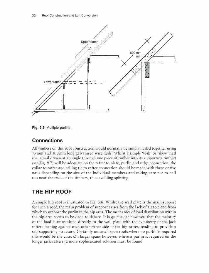
RaftersLittle needs to be said about the common rafters as these can be simply designed from the span tables. However on a very long roof slope it may not be practical to obtain timbers in one continuous length. On roof slopes in excess of 4.8 m a second purlin should be considered as illustrated in Fig. 3.5. A collar should be fitted on every pair of rafters immediately beneath the ridge, and a further collar should be fitted to every other pair of rafters immediately above the purlin position.
Ceiling joistEven on most domestic roof spans it will be impractical to obtain a ceiling joist member in one length. It will also be necessary, unless very large ceiling joists are used, to support the ceiling joist at some point along its length, by suspending it from the structure above and/or on a structural wall below. Figure 3.1 shows the typical solution using hangers and binders. More information on a typical hanger and binder combination for supporting the ceiling joists can be found in Chapter 5.
Fig. 3.4 Purlin struts.
32 Roof Construction and Loft Conversion
ConnectionsAll timbers on this roof construction would normally be simply nailed together using 75 mm and 100 mm long galvanised wire nails. Whilst a simple ‘tosh’ or ‘skew’ nail (i.e. a nail driven at an angle through one piece of timber into its supporting timber) (see Fig. 9.7) will be adequate on the rafter to plate, purlin and ridge connection, the collar to rafter and ceiling tie to rafter connection should be made with three or five nails depending on the size of the individual members and taking care not to nail too near the ends of the timbers, thus avoiding splitting.
THE HIP ROOF
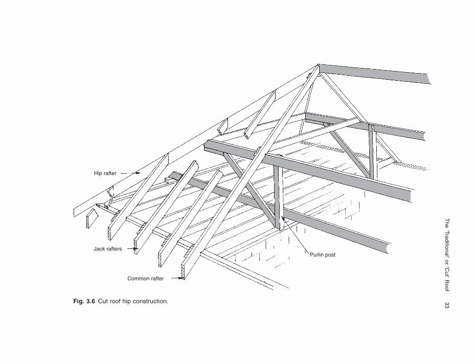
A simple hip roof is illustrated in Fig. 3.6. Whilst the wall plate is the main support for such a roof, the main problem of support arises from the lack of a gable end from which to support the purlin in the hip area. The mechanics of load distribution within the hip area seems to be open to debate. It is quite clear however, that the majority of the load is transmitted directly to the wall plate with the symmetry of the jack rafters leaning against each other either side of the hip rafter, tending to provide a self supporting structure. Certainly on small span roofs where no purlin is required this would be the case. On larger spans however, where a purlin is required on the longer jack rafters, a more sophisticated solution must be found.
Fig. 3.5 Multiple purlins.
Upper rafter
Lower rafter
600 mmmin
The ‘Traditional’ or ‘C
ut’ Roof
33Fig. 3.6 Cut roof hip construction.
Hip rafter
Jack rafters
Common rafter
Purlin post
34 Roof Construction and Loft Conversion
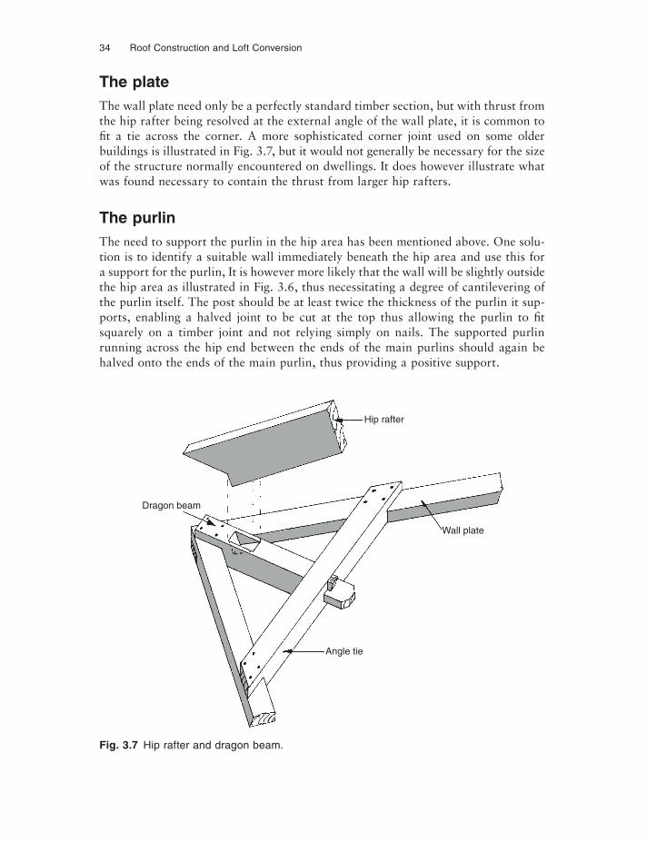
The plateThe wall plate need only be a perfectly standard timber section, but with thrust from the hip rafter being resolved at the external angle of the wall plate, it is common to fi t a tie across the corner. A more sophisticated corner joint used on some older buildings is illustrated in Fig. 3.7, but it would not generally be necessary for the size of the structure normally encountered on dwellings. It does however illustrate what was found necessary to contain the thrust from larger hip rafters.
The purlinThe need to support the purlin in the hip area has been mentioned above. One solu-tion is to identify a suitable wall immediately beneath the hip area and use this for a support for the purlin, It is however more likely that the wall will be slightly outside the hip area as illustrated in Fig. 3.6, thus necessitating a degree of cantilevering of the purlin itself. The post should be at least twice the thickness of the purlin it sup-ports, enabling a halved joint to be cut at the top thus allowing the purlin to fi t squarely on a timber joint and not relying simply on nails. The supported purlin running across the hip end between the ends of the main purlins should again be halved onto the ends of the main purlin, thus providing a positive support.
Fig. 3.7 Hip rafter and dragon beam.
Dragon beam
Hip rafter
Angle tie
Wall plate
The ‘Traditional’ or ‘Cut’ Roof 35
RaftersRafters can be designed as for the more simple roof described earlier – the jack rafters will maintain the same cross-section, be birdsmouthed over the plate and nailed either side of the hip rafter. The angle of cut on the rafter abutting the hip rafter is what is known as a compound angle and this, like many other of the angles neces-sary on timbers in roof structures, can be calculated from the ‘carpenter’s square’ or by reference to such specialist sets of tables as can be found in the Roofing Ready Reckoner (see the bibliography).
Ceiling joistIn the writer’s opinion it is important to maintain the tying effect of the ceiling joist within the hip area and for this reason the ceiling joists should span in the direction indicated in Fig. 3.6. To do this it will be necessary to maintain the support by the binder within the hip area, and whilst the binder can be supported from the cantile-vered purlin, it may be more prudent to have a separate binder beam supported at its ends, on the extreme end of the roof on the wall plate, and on an internal sup-porting partition wall.
THE MONO PITCH ROOF TRUSS
In its simplest form using traditional construction, this is little more than half of a duo pitch roof cut at the ridge, the ridge now becoming the higher outer wall of the building. Purlins can still be used if needed from gable to gable or to an intermediate principal truss with ceiling joists fi tted to rafter at lower wall plate and built into the wall or on joist hangers in the higher or ridge wall, i.e. this becomes half of the illustration Fig. 3.1.
Gable stability strapping, wall plate strapping, ventilation, insulation etc. details can all be found in Chapter 8. Particular attention must be paid to ventilation at the ridge, and there are a number of specially shaped mono pitch ridge tiles which are available, some containing their own ventilation, whilst special ventilated tiles to match the general tiling covering are also available and can be fi tted at the ridge to provide the necessary ventilation.
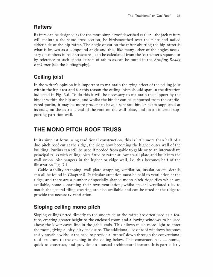
Sloping ceiling mono pitchSloping ceilings fi tted directly to the underside of the rafter are often used as a fea-ture, creating greater height to the enclosed room and allowing windows to be used above the lower eaves line in the gable ends. This allows much more light to enter the room, giving a lofty, airy enclosure. The additional use of roof windows becomes easily possible without the need to provide a ‘tunnel’ down through the conventional roof structure to the opening in the ceiling below. This construction is economic, quick to construct, and provides an unusual architectural feature. It is particularly
36 Roof Construction and Loft Conversion
Fig. 3.8 Sloping ceiling mono pitch roof.
useful for extensions to the eaves side of a conventional two-storey house. Figure 3.8 illustrates this construction.
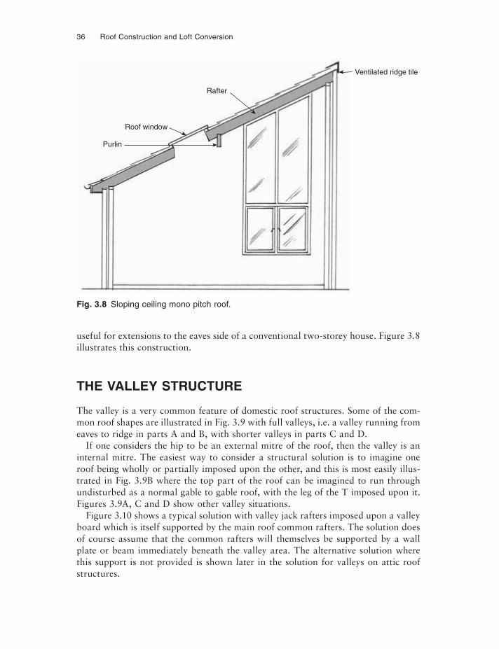
THE VALLEY STRUCTURE
The valley is a very common feature of domestic roof structures. Some of the com-mon roof shapes are illustrated in Fig. 3.9 with full valleys, i.e. a valley running from eaves to ridge in parts A and B, with shorter valleys in parts C and D.
If one considers the hip to be an external mitre of the roof, then the valley is an internal mitre. The easiest way to consider a structural solution is to imagine one roof being wholly or partially imposed upon the other, and this is most easily illus-trated in Fig. 3.9B where the top part of the roof can be imagined to run through undisturbed as a normal gable to gable roof, with the leg of the T imposed upon it. Figures 3.9A, C and D show other valley situations.
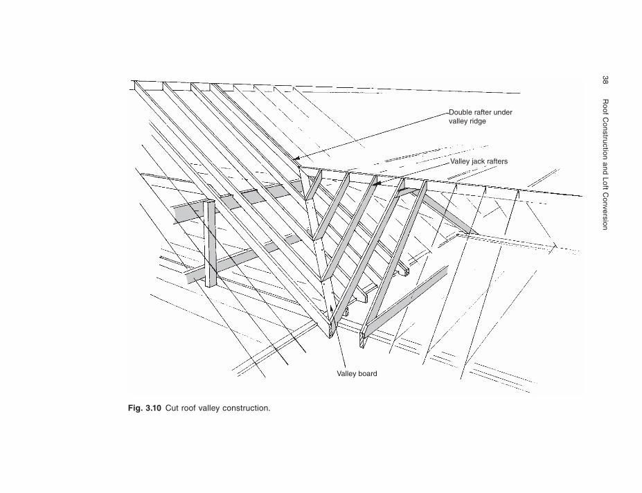
Figure 3.10 shows a typical solution with valley jack rafters imposed upon a valley board which is itself supported by the main roof common rafters. The solution does of course assume that the common rafters will themselves be supported by a wall plate or beam immediately beneath the valley area. The alternative solution where this support is not provided is shown later in the solution for valleys on attic roof structures.
Ventilated ridge tile
Rafter
Roof window
Purlin
The ‘Traditional’ or ‘Cut’ Roof 37
Fig. 3.9 Valley locations.
Hip
A
Ridge
Valley
C D
B
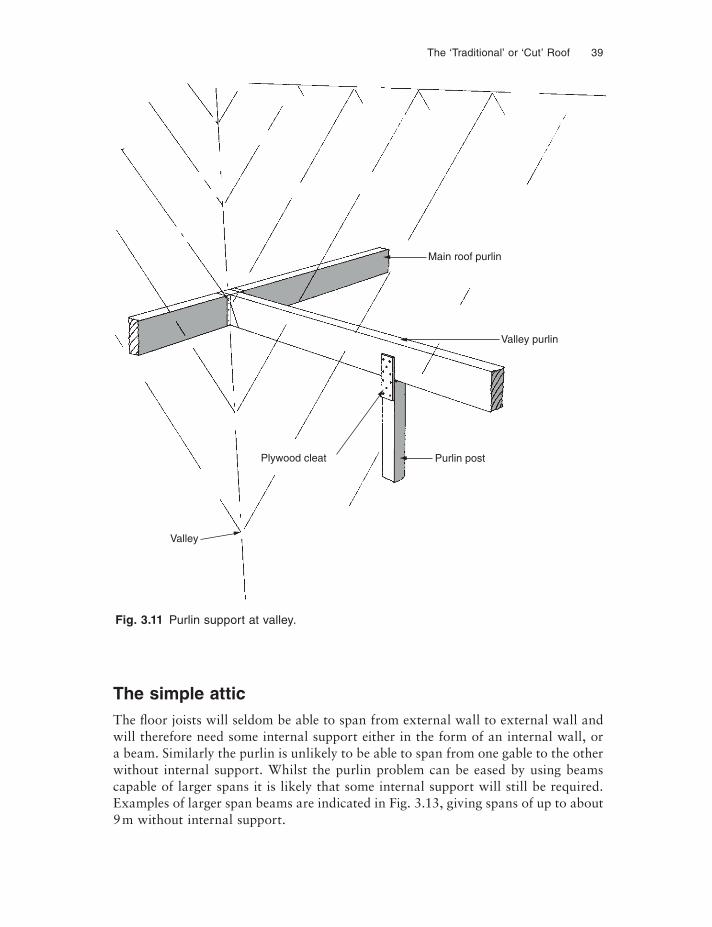
On valleys where the rafter length itself needs purlin support, the purlin in the valley area should be arranged at the same height as the purlin in the main roof. Further-more it should be supported where it passes over the wall plate line of the main roof by a post, and by a steel hanger or shoe where it adjoins the main roof purlin. Figure 3.11 illustrates the purlin connections.
ATTIC ROOFS
The attic or room-in-the-roof construction has become increasingly popular in recent years with the tendency for planners to seek steeper pitched roofs, particularly in rural areas. The house style created is often referred to as a ‘chalet’. On a normal two-storey house with a roof pitch of about 45°, the volume enclosed by the roof is approximately 40% of the volume of the two storeys below, and on a single-storey building this proportion goes up to almost 80%. It therefore makes sense to attempt to use the extra enclosed space provided by the roof structure.
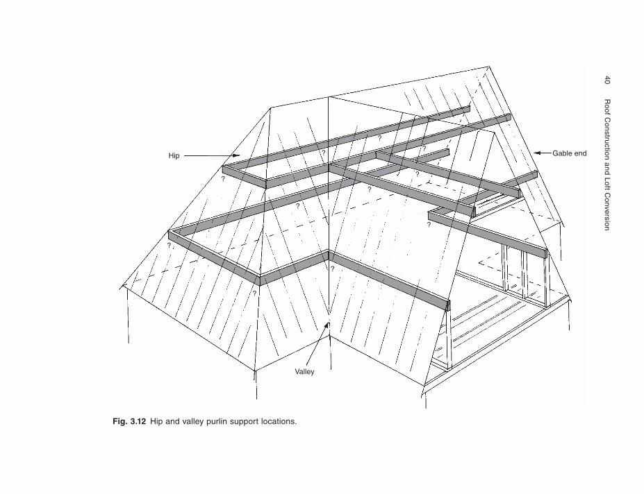
An attic roof structure with gables at both ends is comparatively simple to con-struct using purlins and common rafters; this roof shape can be seen in Chapter 8, Fig. 8.22. The hip end attic however poses some more difficult problems of support within the hip area, with L- or T-shaped roofs posing further problems at the roof intersection. In all cases careful consideration must be given to the support both of the fl oor joists and of the purlins. The question marks in Fig. 3.12 show these problem points.
38
R
oof Construction and Loft C
onversion
Fig. 3.10 Cut roof valley construction.
Valley board
Valley jack rafters
Double rafter undervalley ridge
The ‘Traditional’ or ‘Cut’ Roof 39
Fig. 3.11 Purlin support at valley.
Main roof purlin
Valley purlin
Plywood cleat Purlin post
Valley
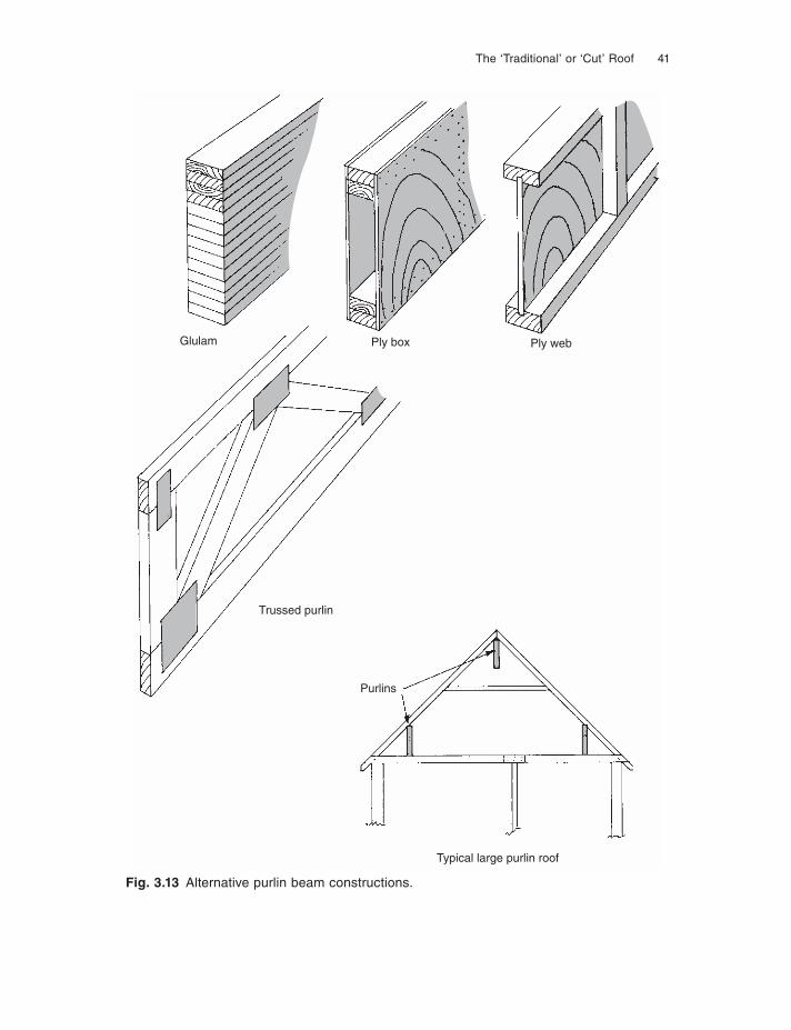
The simple atticThe floor joists will seldom be able to span from external wall to external wall and will therefore need some internal support either in the form of an internal wall, or a beam. Similarly the purlin is unlikely to be able to span from one gable to the other without internal support. Whilst the purlin problem can be eased by using beams capable of larger spans it is likely that some internal support will still be required. Examples of larger span beams are indicated in Fig. 3.13, giving spans of up to about 9 m without internal support.
40
Roof C
onstruction and Loft Conversion
Fig. 3.12 Hip and valley purlin support locations.
Hip
?
?
?
?
?
?
?
?
Valley
?
?
?GableGable end
The ‘Traditional’ or ‘Cut’ Roof 41
Glulam Ply box Ply web
Trussed purlin
Purlins
Typical large purlin roof
Fig. 3.13 Alternative purlin beam constructions.
42 Roof Construction and Loft Conversion
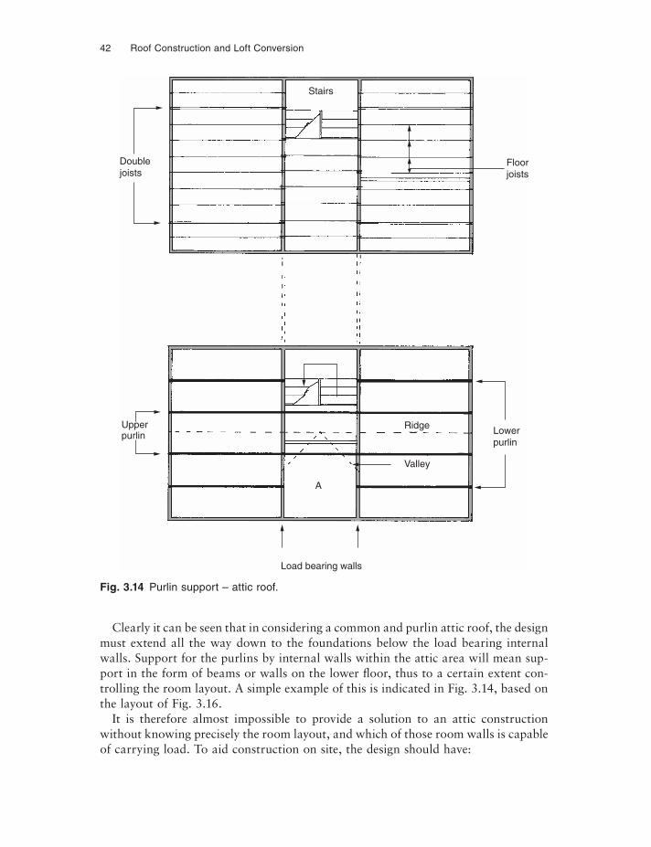
Clearly it can be seen that in considering a common and purlin attic roof, the design must extend all the way down to the foundations below the load bearing internal walls. Support for the purlins by internal walls within the attic area will mean sup-port in the form of beams or walls on the lower fl oor, thus to a certain extent con-trolling the room layout. A simple example of this is indicated in Fig. 3.14, based on the layout of Fig. 3.16.
It is therefore almost impossible to provide a solution to an attic construction without knowing precisely the room layout, and which of those room walls is capable of carrying load. To aid construction on site, the design should have:
Fig. 3.14 Purlin support – attic roof.
Floorjoists
Doublejoists
Upperpurlin
Load bearing walls
Ridge
Valley
Lowerpurlin
A
Stairs
Ridge
Valley
The ‘Traditional’ or ‘C
ut’ Roof
4
3
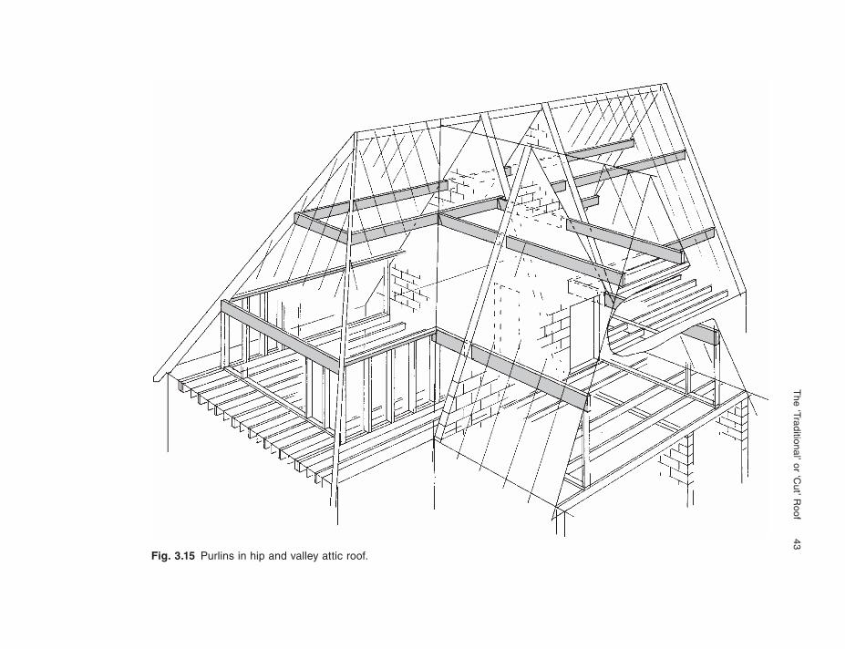
Fig. 3.15 Purlins in hip and valley attic roof.
44 Roof Construction and Loft Conversion
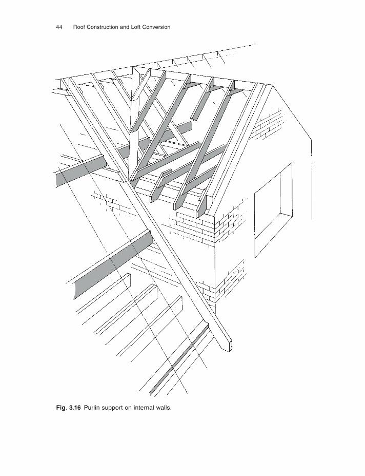
Fig. 3.16 Purlin support on internal walls.
The ‘Traditional’ or ‘Cut’ Roof 45
(1) Common fl oor joist depth;(2) Common rafter depth;(3) Common purlin depth;(4) Common purlin lines.
Structural economy can be achieved by varying the thickness of individual members and/or their grade stress, and the spacing of structural members.
NHBC technical manual now gives guidance on additional strutting that may be required for the fl oor joists, in appendix 7.2–G under the heading ‘Strutting for Attic Trusses and Cut Roofs that have a Floor’. It requires no additional strutting if the distance between the attic truss wall struts are less than 2.5 m, one at the centre of the room width for up to 4.5 m wide, and two equally spaced for rooms over 4.5 m wide. The same applies to cut roofs but in this case the distance criteria is that between the supporting walls for the fl oor structure. Either herringbone strutting (38 mm × 38 mm timber) or solid strutting of not less than three-quarters the depth of the fl oor joist and at least 38 mm thick should be used.
The hip and valley atticHaving highlighted the need for both fl oor joist and purlin support, on a simple attic, consideration must now be given to the solution of the more complicated attic roof as illustrated in Fig. 3.12.
It can be assumed that the fl oor joists will generally be supported either by beams or by load bearing walls below. In some instances these joists may be doubled to form a beam, or a separate beam is inserted within the fl oor which will itself be strong enough not only to carry the fl oor but also to support the purlin above. This however generally applies only to the lower purlin, i.e. the one at the attic wall to the sloping ceiling junction, and not to the upper purlin. The latter is more likely to be supported by internal load bearing walls.
Reference should be made to Fig. 3.15. At the gable end both sets of purlins can simply be built-in in the usual manner, with the fl oor joists supported by being built-in at the gable and either on a load bearing room dividing wall internally or a beam as illustrated.
At the hip end the construction is more complicated, but again fl oor joists can be supported on the wall plate of the external wall and on either a beam or internal load bearing partition. The lower purlin at the end of the hip can be either supported at its ends, strutted up from a specifically designed double joist or beam below, or it can become little more than a wall plate supported by the end wall studs from fl oor joists below. In the latter situation of course the floor joists must be designed to carry this additional load. The side purlins in the hip area are most likely to become in effect wall plates, themselves being supported by studs at 400 mm or 600 mm centres, the studs being supported by the double joist or beam below. If the side wall is to be omitted to give maximum fl oor space then the purlin must be capable of spanning the room width and will need to be supported by room dividing walls.
46 Roof Construction and Loft Conversion
The upper purlin will generally span from gable to internal load bearing walls and then from internal load bearing walls to further load bearing internal walls as illus-trated. However in the hip area it is not possible to provide an adequate cantilever length, bearing in mind minimum room size requirements, and it is certainly not possible to provide a strut as illustrated in Fig. 3.6. The purlin at the hip rafter junction therefore may well have to be supported by the hip rafter itself, thus making the hip rafter a major structural element. Where this is the case it will not be possible to design the roof structurally from Table 3.1 and design advice must be sought. For the purposes of the illustration such a structural rafter has been assumed.
The valley intersection
The lower purlin in Fig. 3.15 is supported by the internal load bearing wall and will to a certain extent cantilever into the valley area. However additional support may be provided by a post down onto the beam provided in the fl oor of the main roof structure. The upper purlin again supported by the internal load bearing wall will not be able to provide a full cantilever and must therefore be connected into the purlin within the main roof structure. The connection will normally be by a steel shoe and is of course following a similar structural layout to that indicated in Fig. 3.11, with the purlin post being replaced by the internal wall. Rafters, collars and ridge may be provided bearing in mind the considerations described earlier, especially concerning rafter length.
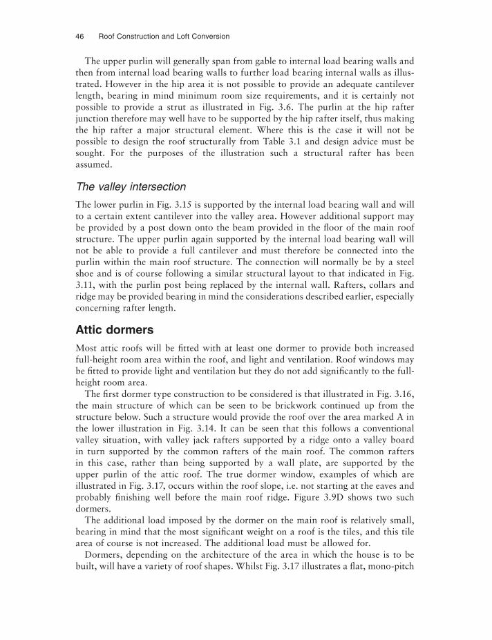
Attic dormersMost attic roofs will be fi tted with at least one dormer to provide both increased full-height room area within the roof, and light and ventilation. Roof windows may be fi tted to provide light and ventilation but they do not add significantly to the full-height room area.
The fi rst dormer type construction to be considered is that illustrated in Fig. 3.16, the main structure of which can be seen to be brickwork continued up from the structure below. Such a structure would provide the roof over the area marked A in the lower illustration in Fig. 3.14. It can be seen that this follows a conventional valley situation, with valley jack rafters supported by a ridge onto a valley board in turn supported by the common rafters of the main roof. The common rafters in this case, rather than being supported by a wall plate, are supported by the upper purlin of the attic roof. The true dormer window, examples of which are illustrated in Fig. 3.17, occurs within the roof slope, i.e. not starting at the eaves and probably fi nishing well before the main roof ridge. Figure 3.9D shows two such dormers.
The additional load imposed by the dormer on the main roof is relatively small, bearing in mind that the most significant weight on a roof is the tiles, and this tile area of course is not increased. The additional load must be allowed for.
Dormers, depending on the architecture of the area in which the house is to be built, will have a variety of roof shapes. Whilst Fig. 3.17 illustrates a flat, mono-pitch
The ‘Traditional’ or ‘Cut’ Roof 47
Fig. 3.17 Dormer styles.
48 Roof Construction and Loft Conversion
or ‘catslide’ and a conventional symmetrically pitched roof with gable ends, hip end dormers are not uncommon.
Dormer framework
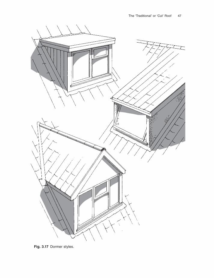
The construction of the dormer is relatively simple. The critical part of the design is the forming of an adequately strong framed opening within the main roof. In forming the hole for the dormer, the continuity of roof slope support is removed and provision must be made to carry the load both above and below the opening formed. If an up-per and lower purlin are used in the attic structure, then these members may be used to support the rafters both above and below the opening. The perimeter of the hole formed in the main roof will provide the foundation for the dormer framework itself. Figure 3.18a illustrates the method of imposing a simple dormer framework onto a trimmed opening. Figure 3.18b illustrates the rules for trimmer numbers.
ROOF LIGHTS AND ROOF WINDOWS
Roof lights generally will require much smaller openings within the main roof struc-ture than a dormer described above, therefore a similar method to that illustrated in Fig. 3.18 will be more than adequate. However, as the roof lights may not extend up the roof slope the full distance between two purlins, separate secondary purlins or trimmers may have to be introduced. If this is the case the rafters onto which the trimmers are fi xed must be reinforced by attaching an additional rafter to each side of the opening, these additional rafters extending from the lower to the upper purlin (see Fig. 8.26).
The term ‘roof window’ is a term recently introduced to the building industry to describe what is in effect an opening roof light. The roof light is normally fixed, of course, and provides only light to the building. Roof windows are most commonly of proprietary manufacture with the manufacturers providing detailed guidance on the method of fi tting the roof window to both existing and new roof structures. Reference should be made to the manufacturer’s instructions if such a roof window is to be fitted.
The advantage of the roof window over the dormer, if additional fl oor space is not the criterion, is that because the glaze area is angled directly at the sky, signifi -cantly more light is admitted to the room. The manufacturers of the proprietary roof windows also claim up to 70% saving in cost over a comparable dormer construction.
ADDITIONAL DESIGN CONSIDERATIONS
New houses constructed under the control of the National House-Building Council must further conform to the requirements of the Registered House-Builder’s Hand-book, Volume 2 of which sets out the technical requirements for the design and
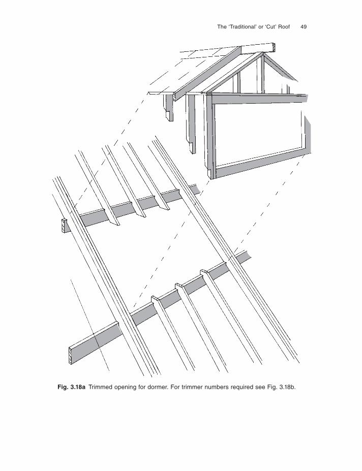
The ‘Traditional’ or ‘Cut’ Roof 49
Fig. 3.18a Trimmed opening for dormer. For trimmer numbers required see Fig. 3.18b.
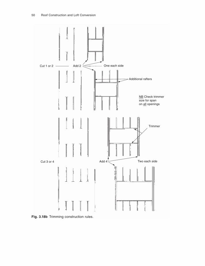
50 Roof Construction and Loft Conversion
One each side
Additional rafters
Trimmer
Two each sideCut 3 or 4
Cut 1 or 2
Add 4
Add 2
NB Check trimmersize for spanon all openings
Fig. 3.18b Trimming construction rules.
The ‘Traditional’ or ‘Cut’ Roof 51
construction of dwellings. The reader is directed particularly to the section on carpentry, Chapter 7.2.
Chapter 8 of this book concerns itself with the many other aspects of roof con-struction which apply to all roof forms. The items covered are as follows:
(1) Storage and handling of timber;(2) Preservative treatment;(3) Wall plates and straps;(4) Gable ends, straps and gable ladders;(5) Water tank platforms;(6) Ventilation of roof voids;(7) Roof bracing;(8) Eaves details;(9) Trimming small openings.
This chapter has dealt with the construction of new attic roofs. Chapters 9–12 explore the possibilities, problems and solutions when converting loft spaces to form attic rooms.
Chapter 4
Attic Construction Using Modern Engineered Timber Components
The considerable growth in the use of attic construction to make the maximum use of the building envelope, coupled with the lack of skilled building labour, has resulted in the rapid development of engineered timber components for use not only in floors, but also in the construction of the roof element itself. This chapter addresses the de-velopments, many of which, like trussed rafters, are trade-named products developed by specialist timber engineering companies. For that reason some of the illustrations in this chapter, like those in Chapter 6 which deals with trussed rafter systems, are drawn from the various manufacturers’ technical and trade literature.
THE FLOOR
Engineered timber in the various forms illustrated in Fig. 3.13 has existed for some considerable time. However, the demand from the house building industry in general for a product of better quality than solid timber coupled with the need for faster in-stallation and also a stiffer fl oor without creaks and squeaks, has lead to an explosion of engineered timber ‘joists’. A recently reported statistic indicates that in 2005 some 50% of all new homes now use such products in their fl oor construction, accounting for around 65 000 houses in the UK alone. Bearing in mind that an engineered timber joist clearly costs considerably more than a simple soft wood joist, it is worth con-sidering the advantages of the product before looking at the various types available and the construction methods used.
(1) Better quality floor constructionA stiffer fl oor giving better ‘feel’ to the user, and a quieter construction avoiding the shrinkage so often associated with conventional timber. Most engineered joist systems strongly recommend that the fl oor deck is screwed and/or glued to the surface to prevent floorboard joint movement.
(2) Faster constructionClaims of 66% reduction in time to install the fl oor, i.e. typically half a day to install an engineered fl oor compared to one and a half days with traditional
Attic Construction Using Modern Engineered Timber Components 53
construction. With an engineered fl oor the fl oor joist system is delivered as a pack of premanufactured components to precise length, including trimmers and blockings etc., where as with traditional construction, soft wood joists to the nearest standard available length would be delivered which then have to be cut, notched and trimmed as necessary before installation.
(3) Reduced costNo wastage – every joist and trimmer is engineered to fi t, and the better quality fl oor means no remedial costs in correcting shrinkage problems for the house builder.
Engineered timber, being a manufactured product, often carries a proprietary name such as Truss Joist, Parallam, Posi-Joist, BCI Joist, Finn Joist etc. but they fall into three main categories:
(1) ‘I’ beams;(2) Laminated solid timber;(3) Fabricated timber using metal connector plates.
All of these fabrications seek to engineer the natural defects of solid soft wood out of the product, i.e. knots, splits, variable slope of grain and density, to provide a stronger product of higher overall performance than that of its individual compo-nents, generally resulting in a better span to depth ratio than solid natural timber, without the associated shrinkage and distortion which occurs even with dry timbers. The following is a review of the different types listed above.
‘I’ beamsThese concentrate the forces imposed on the component when being used as a joist, beam, purlin or rafter into the top and bottom flanges resulting in the ‘I’ shape so familiar with steel beams. A clear advantage is that they are lighter to handle com-pared to a solid timber beam of similar performance. The flange, i.e. the top and bottom member, can either be in solid conventional timber, or a further piece of en-gineered timber similar to the laminated timber described below. The web is again constructed of a man-made timber product, which could be highly compressed timber fi bres commonly known as hardboard, or OSB (oriented strand board) or plywood. The flanges and web are usually joined by high performance gluing in the factory. When being made to specific length, the ends will usually be solid blocked to carry the stresses at the load bearing point (see Fig. 4.1).
Laminated solid timberGlulam is of course laminated solid timber and can be seen in Fig. 3.13. However, most of the laminated timbers used as joists, beams and purlins etc. now use much thinner laminates and are more akin to plywood construction in the thickness of the veneers (see Fig. 4.2), than the traditional 30 mm or 40 mm thick laminates used with
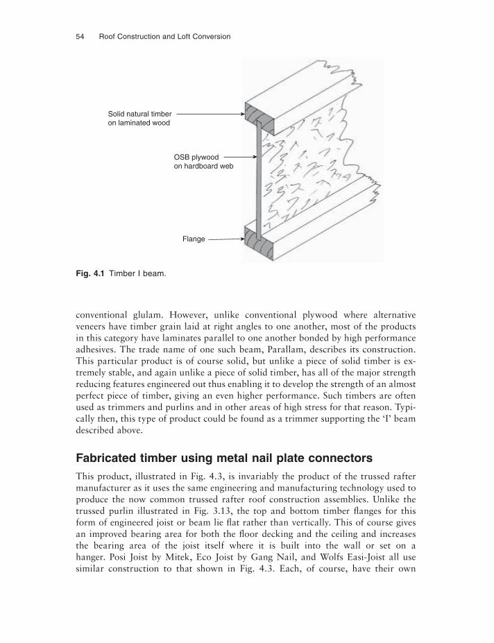
54 Roof Construction and Loft Conversion
conventional glulam. However, unlike conventional plywood where alternative veneers have timber grain laid at right angles to one another, most of the products in this category have laminates parallel to one another bonded by high performance adhesives. The trade name of one such beam, Parallam, describes its construction. This particular product is of course solid, but unlike a piece of solid timber is ex-tremely stable, and again unlike a piece of solid timber, has all of the major strength reducing features engineered out thus enabling it to develop the strength of an almost perfect piece of timber, giving an even higher performance. Such timbers are often used as trimmers and purlins and in other areas of high stress for that reason. Typi-cally then, this type of product could be found as a trimmer supporting the ‘I’ beam described above.
Fabricated timber using metal nail plate connectorsThis product, illustrated in Fig. 4.3, is invariably the product of the trussed rafter manufacturer as it uses the same engineering and manufacturing technology used to produce the now common trussed rafter roof construction assemblies. Unlike the trussed purlin illustrated in Fig. 3.13, the top and bottom timber flanges for this form of engineered joist or beam lie flat rather than vertically. This of course gives an improved bearing area for both the fl oor decking and the ceiling and increases the bearing area of the joist itself where it is built into the wall or set on a hanger. Posi Joist by Mitek, Eco Joist by Gang Nail, and Wolfs Easi-Joist all use similar construction to that shown in Fig. 4.3. Each, of course, have their own
Fig. 4.1 Timber I beam.
Solid natural timberon laminated wood
OSB plywoodon hardboard web
Flange
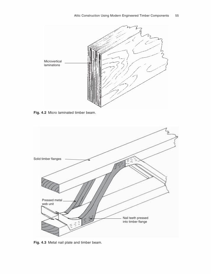
Attic Construction Using Modern Engineered Timber Components 55
Microverticallaminations
Solid timber flanges
Pressed metalweb unit
Nail teeth pressedinto timber flange
Fig. 4.2 Micro laminated timber beam.
Fig. 4.3 Metal nail plate and timber beam.
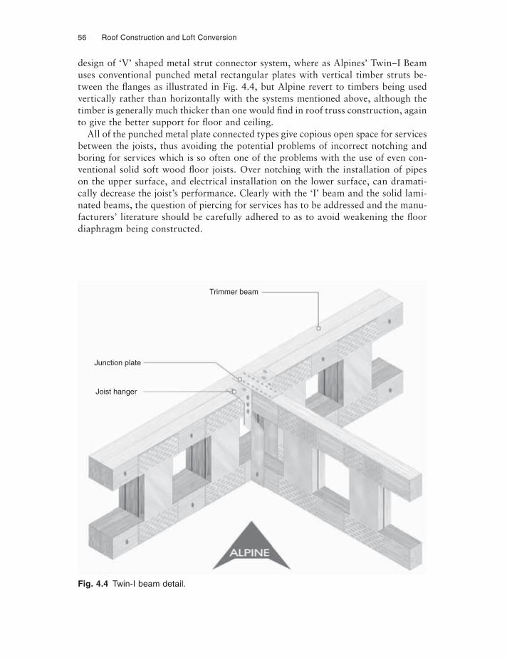
56 Roof Construction and Loft Conversion
design of ‘V’ shaped metal strut connector system, where as Alpines’ Twin–I Beam uses conventional punched metal rectangular plates with vertical timber struts be-tween the flanges as illustrated in Fig. 4.4, but Alpine revert to timbers being used vertically rather than horizontally with the systems mentioned above, although the timber is generally much thicker than one would find in roof truss construction, again to give the better support for fl oor and ceiling.
All of the punched metal plate connected types give copious open space for services between the joists, thus avoiding the potential problems of incorrect notching and boring for services which is so often one of the problems with the use of even con-ventional solid soft wood fl oor joists. Over notching with the installation of pipes on the upper surface, and electrical installation on the lower surface, can dramati-cally decrease the joist’s performance. Clearly with the ‘I’ beam and the solid lami-nated beams, the question of piercing for services has to be addressed and the manu-facturers’ literature should be carefully adhered to as to avoid weakening the floor diaphragm being constructed.
Trimmer beam
Junction plate
Joist hanger
Fig. 4.4 Twin-I beam detail.
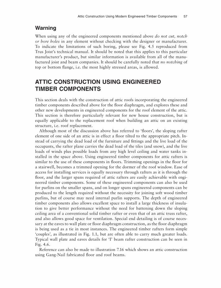
Attic Construction Using Modern Engineered Timber Components 57
WarningWhen using any of the engineered components mentioned above do not cut, notch or bore holes in any element without checking with the designer or manufacturer. To indicate the limitations of such boring, please see Fig. 4.5 reproduced from Trus Joist’s technical manual. It should be noted that this applies to this particular manufacturer’s product, but similar information is available from all of the manu-factured joist and beam companies. It should be carefully noted that no notching of top or bottom flange, i.e. the most highly stressed areas, is allowed.
ATTIC CONSTRUCTION USING ENGINEERED TIMBER COMPONENTS
This section deals with the construction of attic roofs incorporating the engineered timber components described above for the fl oor diaphragm, and explores these and other new developments in engineered components for the roof element of the attic. This section is therefore particularly relevant for new house construction, but is equally applicable to the replacement roof when building an attic on an existing structure, i.e. roof replacement.
Although most of the discussion above has referred to ‘fl oors’, the sloping rafter element of one side of an attic is in effect a fl oor tilted to the appropriate pitch. In-stead of carrying the dead load of the furniture and fi ttings and the live load of the occupants, the rafter plane carries the dead load of the tiles (and snow), and the live loads of winds plus possible loads from any high level ceiling and water tanks in-stalled in the space above. Using engineered timber components for attic rafters is similar to the use of these components in floors. Trimming openings in the floor for a stairwell, becomes a trimmed opening for the dormer of the roof window. Ease of access for installing services is equally necessary through rafters as it is through the fl oor, and the larger spans required of attic rafters are easily achievable with engi-neered timber components. Some of these engineered components can also be used for purlins on the smaller spans, and on longer spans engineered components can be produced to the length required without the necessity for joining soft wood timber purlins, but of course may need internal purlin supports. The depth of engineered timber components also allows excellent space to install a large thickness of insula-tion to give better performance without the need for battening down the sloping ceiling area of a conventional solid timber rafter or even that of an attic truss rafter, and also allows good space for ventilation. Special end detailing is of course neces-sary at the eaves to wall plate or fl oor diaphragm construction, as the fl oor diaphragm is being used as a tie in most instances. The engineered timber rafters form simple ‘couples’, as illustrated in Fig. 1.1, but are often able to carry much greater loads. Typical wall plate and eaves details for ‘I’ beam rafter construction can be seen in Fig. 4.6.
Reference can also be made to illustration 7.16 which shows an attic construction using Gang-Nail fabricated fl oor and roof beams.
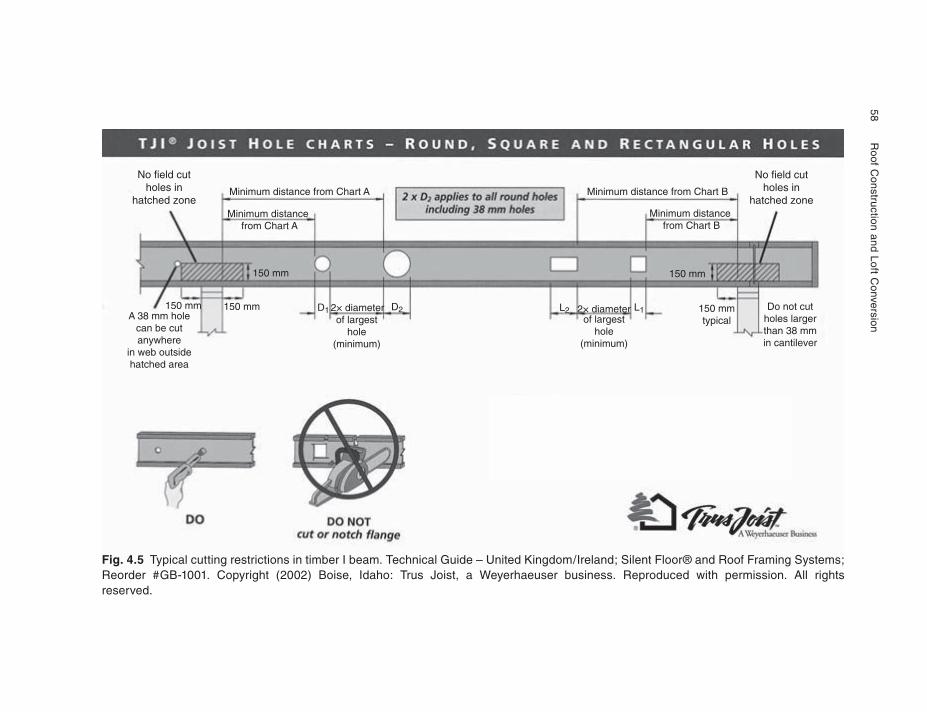
58
Roof C
onstruction and Loft Conversion
No field cutholes in
hatched zone
No field cutholes in
hatched zone
2× diameter 2× diameter L1L2of largest
hole(minimum)
of largesthole
(minimum)
Minimum distance from Chart A Minimum distance from Chart B
Minimum distance from Chart A
Minimum distance from Chart B
A 38 mm holecan be cutanywhere
in web outsidehatched area
Do not cutholes largerthan 38 mmin cantilever
150 mmtypical
150 mm 150 mm
150 mm D1 D2150 mm
Fig. 4.5 Typical cutting restrictions in timber I beam. Technical Guide – United Kingdom/Ireland; Silent Floor® and Roof Framing Systems; Reorder #GB-1001. Copyright (2002) Boise, Idaho: Trus Joist, a Weyerhaeuser business. Reproduced with permission. All rights reserved.
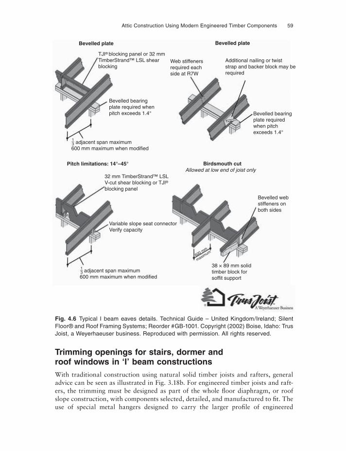
Attic Construction Using Modern Engineered Timber Components 59
Fig. 4.6 Typical I beam eaves details. Technical Guide – United Kingdom/Ireland; Silent Floor® and Roof Framing Systems; Reorder #GB-1001. Copyright (2002) Boise, Idaho: Trus Joist, a Weyerhaeuser business. Reproduced with permission. All rights reserved.
Trimming openings for stairs, dormer and roof windows in ‘I’ beam constructionsWith traditional construction using natural solid timber joists and rafters, general advice can be seen as illustrated in Fig. 3.18b. For engineered timber joists and raft-ers, the trimming must be designed as part of the whole fl oor diaphragm, or roof slope construction, with components selected, detailed, and manufactured to fit. The use of special metal hangers designed to carry the larger profile of engineered
TJI® blocking panel or 32 mmTimberStrand™ LSL shearblocking
Web stiffenersrequired eachside at R7W
Bevelled bearingplate required whenpitch exceeds 1.4°
adjacent span maximum600 mm maximum when modified
adjacent span maximum600 mm maximum when modified
32 mm TimberStrand™ LSLV-cut shear blocking or TJI®
blocking panel
Allowed at low end of joist only
Bevelled webstiffeners onboth sides
38 × 89 mm solidtimber block forsoffit support
600 mm
maximum
Variable slope seat connectorVerify capacity
Bevelled bearingplate requiredwhen pitchexceeds 1.4°
Additional nailing or twiststrap and backer block may berequired
Bevelled plate
Pitch limitations: 14°–45° Birdsmouth cut
Bevelled plate
13–
13–
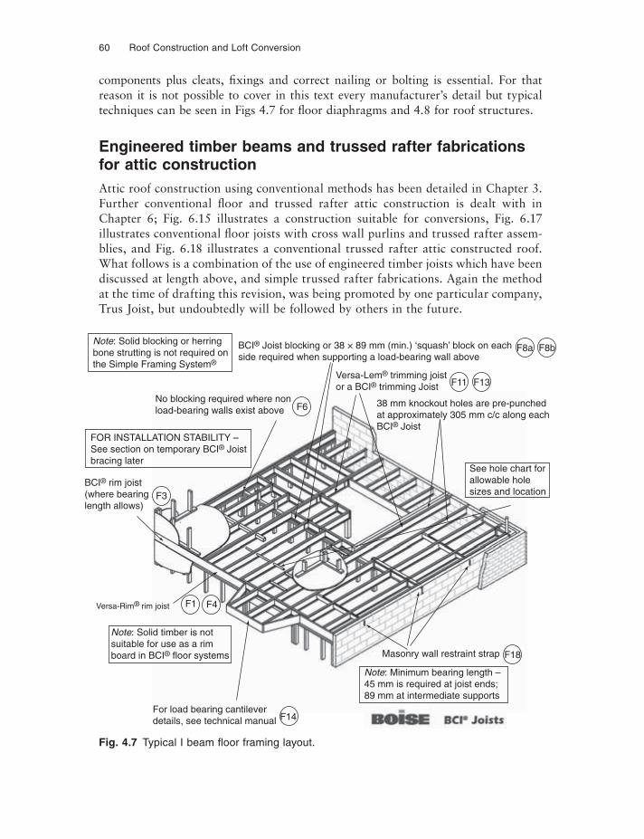
60 Roof Construction and Loft Conversion
components plus cleats, fi xings and correct nailing or bolting is essential. For that reason it is not possible to cover in this text every manufacturer’s detail but typical techniques can be seen in Figs 4.7 for fl oor diaphragms and 4.8 for roof structures.
Engineered timber beams and trussed rafter fabrications for attic constructionAttic roof construction using conventional methods has been detailed in Chapter 3. Further conventional fl oor and trussed rafter attic construction is dealt with in Chapter 6; Fig. 6.15 illustrates a construction suitable for conversions, Fig. 6.17 illustrates conventional fl oor joists with cross wall purlins and trussed rafter assem-blies, and Fig. 6.18 illustrates a conventional trussed rafter attic constructed roof. What follows is a combination of the use of engineered timber joists which have been discussed at length above, and simple trussed rafter fabrications. Again the method at the time of drafting this revision, was being promoted by one particular company, Trus Joist, but undoubtedly will be followed by others in the future.
Fig. 4.7 Typical I beam fl oor framing layout.
Note: Solid blocking or herringbone strutting is not required onthe Simple Framing System®
BCI® rim joist(where bearinglength allows)
Versa-Rim® rim joist
Masonry wall restraint strap
BCI® Joist blocking or 38 × 89 mm (min.) ‘squash’ block on eachside required when supporting a load-bearing wall above
Versa-Lem® trimming joistor a BCI® trimming Joist
38 mm knockout holes are pre-punchedat approximately 305 mm c/c along eachBCI® Joist
No blocking required where nonload-bearing walls exist above
Note: Solid timber is notsuitable for use as a rimboard in BCI® floor systems
See hole chart forallowable holesizes and location
FOR INSTALLATION STABILITY –See section on temporary BCI® Joistbracing later
F3
F1 F4
For load bearing cantileverdetails, see technical manual F14
F18
F13
F8a F8b
F11
F6
Note: Minimum bearing length –45 mm is required at joist ends;89 mm at intermediate supports
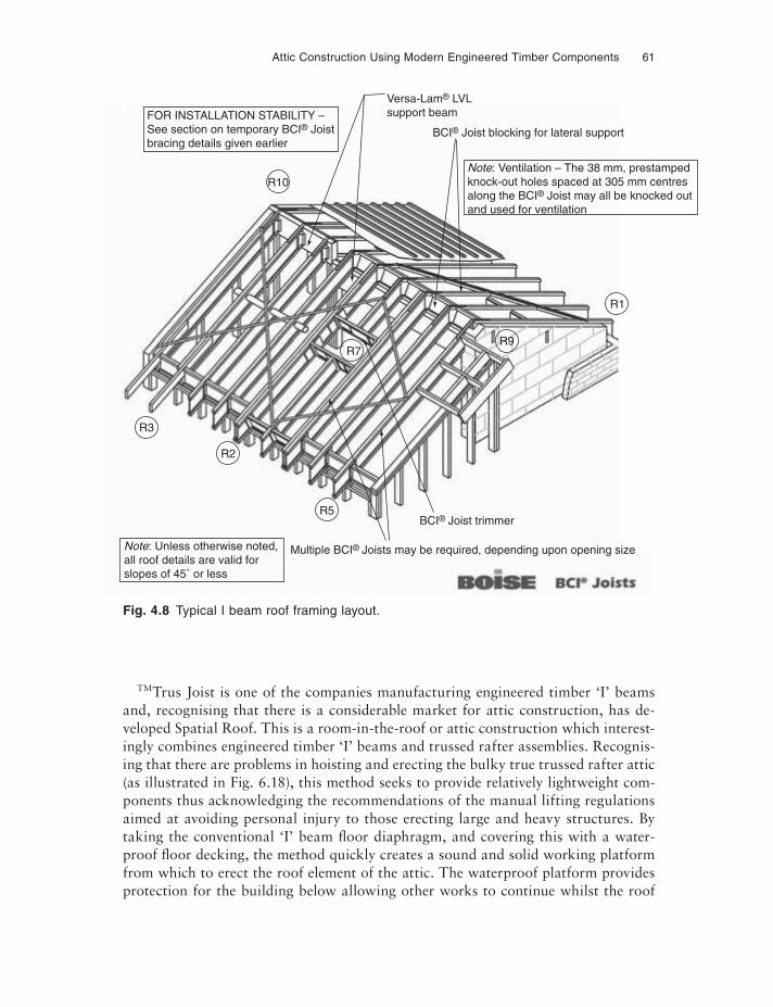
Attic Construction Using Modern Engineered Timber Components 61
TMTrus Joist is one of the companies manufacturing engineered timber ‘I’ beams and, recognising that there is a considerable market for attic construction, has de-veloped Spatial Roof. This is a room-in-the-roof or attic construction which interest-ingly combines engineered timber ‘I’ beams and trussed rafter assemblies. Recognis-ing that there are problems in hoisting and erecting the bulky true trussed rafter attic (as illustrated in Fig. 6.18), this method seeks to provide relatively lightweight com-ponents thus acknowledging the recommendations of the manual lifting regulations aimed at avoiding personal injury to those erecting large and heavy structures. By taking the conventional ‘I’ beam fl oor diaphragm, and covering this with a water-proof fl oor decking, the method quickly creates a sound and solid working platform from which to erect the roof element of the attic. The waterproof platform provides protection for the building below allowing other works to continue whilst the roof
FOR INSTALLATION STABILITY –See section on temporary BCI® Joistbracing details given earlier
Note: Ventilation – The 38 mm, prestampedknock-out holes spaced at 305 mm centresalong the BCI® Joist may all be knocked outand used for ventilation
Note: Unless otherwise noted,all roof details are valid forslopes of 45˚ or less
R10
BCI® Joist trimmer
BCI® Joist blocking for lateral support
Versa-Lam® LVLsupport beam
R2
R5
R1
R9R7
R3
Multiple BCI® Joists may be required, depending upon opening size
Fig. 4.8 Typical I beam roof framing layout.
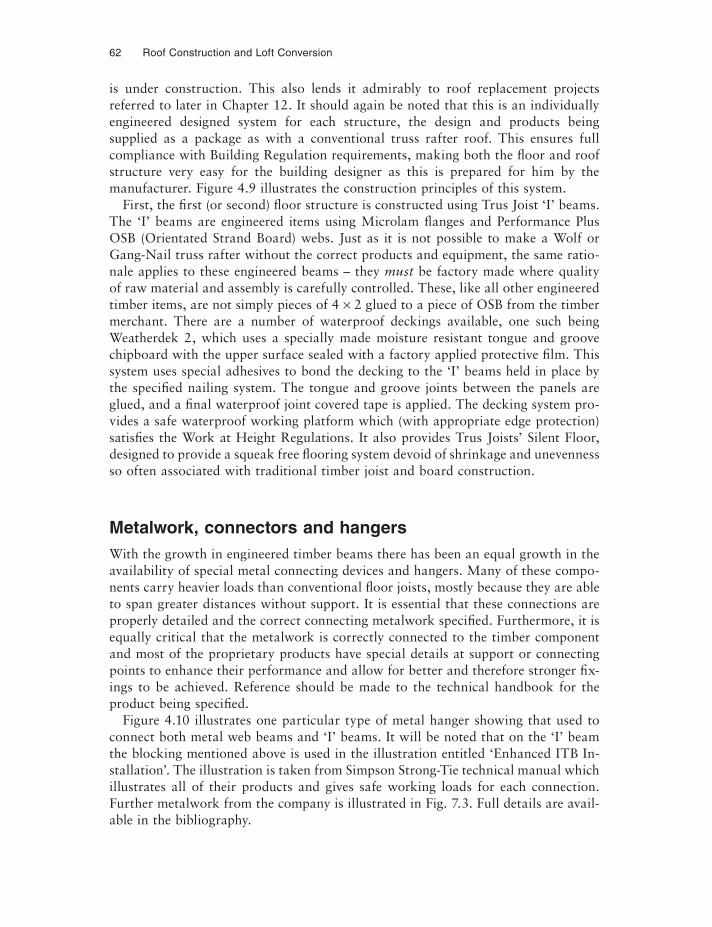
62 Roof Construction and Loft Conversion
is under construction. This also lends it admirably to roof replacement projects referred to later in Chapter 12. It should again be noted that this is an individually engineered designed system for each structure, the design and products being supplied as a package as with a conventional truss rafter roof. This ensures full compliance with Building Regulation requirements, making both the fl oor and roof structure very easy for the building designer as this is prepared for him by the manufacturer. Figure 4.9 illustrates the construction principles of this system.
First, the first (or second) fl oor structure is constructed using Trus Joist ‘I’ beams. The ‘I’ beams are engineered items using Microlam flanges and Performance Plus OSB (Orientated Strand Board) webs. Just as it is not possible to make a Wolf or Gang-Nail truss rafter without the correct products and equipment, the same ratio-nale applies to these engineered beams – they must be factory made where quality of raw material and assembly is carefully controlled. These, like all other engineered timber items, are not simply pieces of 4 × 2 glued to a piece of OSB from the timber merchant. There are a number of waterproof deckings available, one such being Weatherdek 2, which uses a specially made moisture resistant tongue and groove chipboard with the upper surface sealed with a factory applied protective film. This system uses special adhesives to bond the decking to the ‘I’ beams held in place by the specifi ed nailing system. The tongue and groove joints between the panels are glued, and a final waterproof joint covered tape is applied. The decking system pro-vides a safe waterproof working platform which (with appropriate edge protection) satisfies the Work at Height Regulations. It also provides Trus Joists’ Silent Floor, designed to provide a squeak free flooring system devoid of shrinkage and unevenness so often associated with traditional timber joist and board construction.
Metalwork, connectors and hangersWith the growth in engineered timber beams there has been an equal growth in the availability of special metal connecting devices and hangers. Many of these compo-nents carry heavier loads than conventional fl oor joists, mostly because they are able to span greater distances without support. It is essential that these connections are properly detailed and the correct connecting metalwork specifi ed. Furthermore, it is equally critical that the metalwork is correctly connected to the timber component and most of the proprietary products have special details at support or connecting points to enhance their performance and allow for better and therefore stronger fix-ings to be achieved. Reference should be made to the technical handbook for the product being specifi ed.
Figure 4.10 illustrates one particular type of metal hanger showing that used to connect both metal web beams and ‘I’ beams. It will be noted that on the ‘I’ beam the blocking mentioned above is used in the illustration entitled ‘Enhanced ITB In-stallation’. The illustration is taken from Simpson Strong-Tie technical manual which illustrates all of their products and gives safe working loads for each connection. Further metalwork from the company is illustrated in Fig. 7.3. Full details are avail-able in the bibliography.
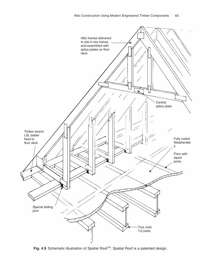
Attic Construction Using Modern Engineered Timber Components 63
Fig. 4.9 Schematic illustration of Spatial RoofTM. Spatial Roof is a patented design.
Attic frames deliveredto site in two halvesand assembled withsplice plates on floordeck
Timber strandLSL ladderfixed tofloor deck
Special slidingjoint
Trus JoistTJI joists
Fully nailedWeatherdek2
Floor withtapedjoints
Centralsplice plate
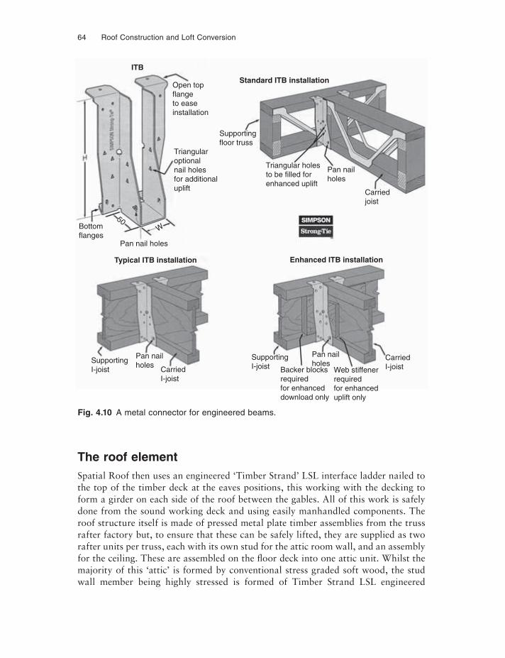
64 Roof Construction and Loft Conversion
The roof elementSpatial Roof then uses an engineered ‘Timber Strand’ LSL interface ladder nailed to the top of the timber deck at the eaves positions, this working with the decking to form a girder on each side of the roof between the gables. All of this work is safely done from the sound working deck and using easily manhandled components. The roof structure itself is made of pressed metal plate timber assemblies from the truss rafter factory but, to ensure that these can be safely lifted, they are supplied as two rafter units per truss, each with its own stud for the attic room wall, and an assembly for the ceiling. These are assembled on the fl oor deck into one attic unit. Whilst the majority of this ‘attic’ is formed by conventional stress graded soft wood, the stud wall member being highly stressed is formed of Timber Strand LSL engineered
Fig. 4.10 A metal connector for engineered beams.
ITB
Typical ITB installation Enhanced ITB installation
Standard ITB installationOpen topflangeto easeinstallation
Supportingfloor truss
Triangularoptionalnail holesfor additionaluplift
Pan nail holes
W
50Bottomflanges
Pan nailholes
Pan nailholes
CarriedI-joist
CarriedI-joist
SupportingI-joist Backer blocks
requiredfor enhanceddownload only
Web stiffenerrequiredfor enhanceduplift only
SupportingI-joist
Triangular holesto be filled forenhanced uplift
Pan nailholes
Carriedjoist
Attic Construction Using Modern Engineered Timber Components 65
timber. A special detail at the base ensures the interface ladder controls the horizontal spread, but allows the fl oor deck to deflect under load independent of the roof struc-ture. This simple construction is suitable for both the professional builder and the self-build enthusiast because it does not involve the use of cranes or other heavy lift-ing equipment and allows easy and safe working whilst allowing the contractor to use the very latest timber engineering technology.
The normal rules apply for the trimming of openings both in the roof and the floor diaphragm. Spatial Roof, Timber Strand LSL and Trus Joist Silent Floor are all reg-istered trade marks and copyright of Trus Joist, full details of which can be found in the bibliography.
Panels, insulated panels and cassette constructed atticsRoof panels and cassette construction continue the current trend towards factory produced engineered timber components. In principle they are a panel comprised of rafter and decking or multiple purlin and decking, i.e. prefabricated structural com-ponents running from wall plate to ridge or gable to gable (or some other internal cross roof supporting wall). The simplest prefabrication is a panel comprised of ply or similar sheathing fixed to rafters; the insulated panel is as above but with insula-tion usually a weatherproof rigid foam applied between the rafters. The cassette is a more complete component in that it provides water resistant sheathing, insulation encapsulated in an integral ceiling, i.e. a component with waterproof sarking or upper cladding, the structure in the form of the joists, insulation, and a ceiling which is either ready for decoration, or can have some other decorative cladding applied over it.
PanelsTRADA offers design guidance on panel roof construction in their Wood Informa-tion Sheet ‘Room in the Roof Construction for New Houses’. The panel consists of a stress graded softwood rafter formed into panels by cladding with ply, OSB or other suitable sheathing. For larger spans the method would require engineered stress skin design where the decking thickness and specification plus nailing or gluing cen-tres would be closely specifi ed by the structural engineer to ensure full performance of the panel. TRADA have championed this form of construction for many years, but it appears that the economic climate and lack of skilled labour are now right for it to come to the fore.
In its simplest form the method is no more than sheathed rafters resting on ridge and over purlins and on the wall plate. The more engineered versions of the panel roof uses panels designed to span from ridge to a thrust plate at the ‘wall plate’ posi-tion, giving a completely free triangular attic space maximising the attic volume. Figure 4.11 is taken from the TRADA sheet referred to above and illustrates the de-sign, but incorporates a ceiling tie because of the relatively large fl oor span and rafter length. The thrust from the roof panel is resisted by the specially shaped hardwood
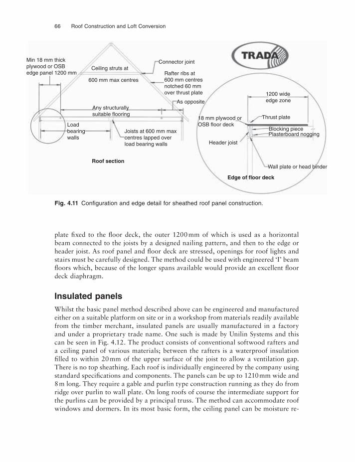
66 Roof Construction and Loft Conversion
plate fixed to the fl oor deck, the outer 1200 mm of which is used as a horizontal beam connected to the joists by a designed nailing pattern, and then to the edge or header joist. As roof panel and fl oor deck are stressed, openings for roof lights and stairs must be carefully designed. The method could be used with engineered ‘I’ beam fl oors which, because of the longer spans available would provide an excellent floor deck diaphragm.
Insulated panelsWhilst the basic panel method described above can be engineered and manufactured either on a suitable platform on site or in a workshop from materials readily available from the timber merchant, insulated panels are usually manufactured in a factory and under a proprietary trade name. One such is made by Unilin Systems and this can be seen in Fig. 4.12. The product consists of conventional softwood rafters and a ceiling panel of various materials; between the rafters is a waterproof insulation fi lled to within 20 mm of the upper surface of the joist to allow a ventilation gap. There is no top sheathing. Each roof is individually engineered by the company using standard specifications and components. The panels can be up to 1210 mm wide and 8 m long. They require a gable and purlin type construction running as they do from ridge over purlin to wall plate. On long roofs of course the intermediate support for the purlins can be provided by a principal truss. The method can accommodate roof windows and dormers. In its most basic form, the ceiling panel can be moisture re-
Min 18 mm thickplywood or OSBedge panel 1200 mm Rafter ribs at
600 mm centresnotched 60 mmover thrust plate
As opposite
Joists at 600 mm maxcentres lapped overload bearing walls
Plasterboard nogging
Wall plate or head binder
Header joist
18 mm plywood orOSB floor deck
Blocking piece
Thrust plate
1200 wideedge zone
Loadbearingwalls
Roof section
Edge of floor deck
Any structurallysuitable flooring
Connector joint
600 mm max centres
Ceiling struts at
Fig. 4.11 Confi guration and edge detail for sheathed roof panel construction.
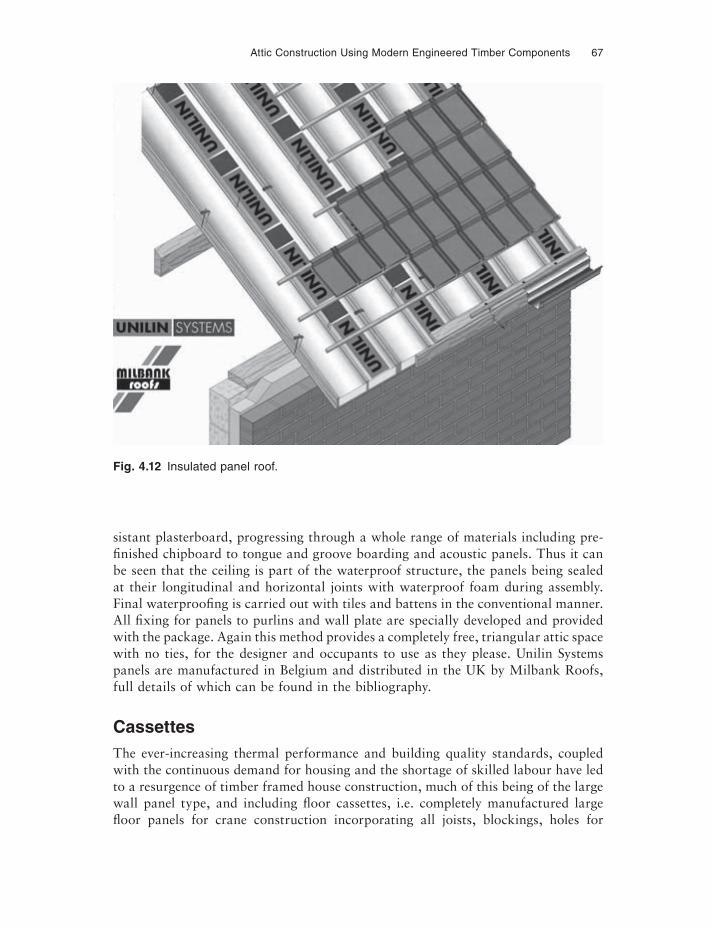
Attic Construction Using Modern Engineered Timber Components 67
Fig. 4.12 Insulated panel roof.
sistant plasterboard, progressing through a whole range of materials including pre-fi nished chipboard to tongue and groove boarding and acoustic panels. Thus it can be seen that the ceiling is part of the waterproof structure, the panels being sealed at their longitudinal and horizontal joints with waterproof foam during assembly. Final waterproofing is carried out with tiles and battens in the conventional manner. All fixing for panels to purlins and wall plate are specially developed and provided with the package. Again this method provides a completely free, triangular attic space with no ties, for the designer and occupants to use as they please. Unilin Systems panels are manufactured in Belgium and distributed in the UK by Milbank Roofs, full details of which can be found in the bibliography.
CassettesThe ever-increasing thermal performance and building quality standards, coupled with the continuous demand for housing and the shortage of skilled labour have led to a resurgence of timber framed house construction, much of this being of the large wall panel type, and including floor cassettes, i.e. completely manufactured large fl oor panels for crane construction incorporating all joists, blockings, holes for
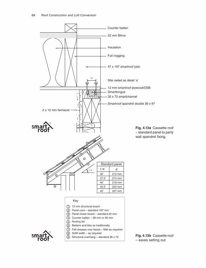
68 Roof Construction and Loft Conversion
Counter batten
22 mm Bitroc
47 x 197 smartroof joist
Site nailed as detail ‘a’
12 mm smartroof plywood/OSBSmarttongue
35 x 72 smartchannel
Smartroof spandrel double 36 x 97
2 x 12 mm fermacel
Insulation
Full nogging
721212
36
7
8
9
5
6
4
1
3
2
Key
12 mm structural boardPanel core – standard 197 mmPanel closer board – standard 22 mmCounter batten – 38 mm or 50 mmRoofing felt
Battens and tiles as traditionally
Felt dresses over fascia – fillet as requiredSoffit width – as requiredStructural overhang – standard 36 x 72
1
2
4
3
7
8
6
5
9
35˚ 212 mm
d
Standard panel
37.5˚ 214 mm
222 mm
218 mm40˚
42.5˚
45˚ 227 mm
˚˚
Fig. 4.13a Cassette roof – standard panel to party wall spandrel fi xing.
Fig. 4.13b Cassette roof – eaves setting out.
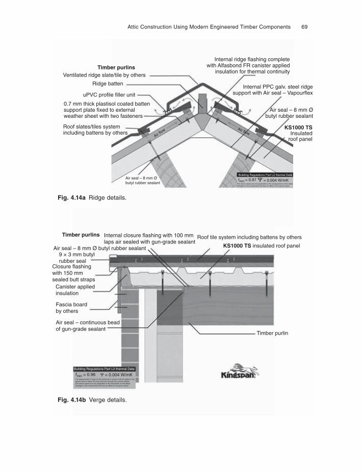
Attic Construction Using Modern Engineered Timber Components 69
Air seal – continuous beadof gun-grade sealant
Building Regulations Part L2 thermal Data
Fascia boardby others
Canister appliedinsulation
Closure flashingwith 150 mmsealed butt straps
The approporiate Ψ value for the brickwork or blocks must be added to theabove value to obtain the total heat loss through this junction details.The above values are only applicable to the cmponents on this detail.Changes to the components will have an effect on the given values.
fmin = 0.96
Timber purlin
9 × 3 mm butylrubber seal
Air seal – 8 mm Ø butyl rubber sealant
Internal closure flashing with 100 mmlaps air sealed with gun-grade sealant
Timber purlins Roof tile system including battens by others
KS1000 TS insulated roof panel
Ψ = 0.004 W/mK
Timber purlinsVentilated ridge slate/tile by others
Air flow Air flow
Roof slates/tiles systemincluding battens by others
0.7 mm thick plastisol coated battensupport plate fixed to externalweather sheet with two fasteners
Ridge batten
Air seal – 8 mm Øbutyl rubber sealant
Internal ridge flashing completewith Alfasbond FR canister applied
insulation for thermal continuity
Internal PPC galv. steel ridgesupport with Air seal – Vapourflex
Air seal – 8 mm Øbutyl rubber sealant
KS1000 TSInsulated
roof panel
The above values are only applicable to the compponents on this detail.Changes to the components will have an effect on the given values.
fmin = 0.97Building Regulations Part L2 thermal Data
Ψ = 0.004 W/mK
uPVC profile filler unit
Fig. 4.14a Ridge details.
Fig. 4.14b Verge details.
70 Roof Construction and Loft Conversion
services and prefixed weatherproofed deckings. The factories making these lend themselves ideally to manufacturing roof cassettes. The crane for the erection of these large roof cassettes is already on site having assembled the timber framed house or lowered the fl oor cassette on to a traditional constructed building. Most of these systems therefore come from timber framed housing manufacturers.
Tradis is one such cassette developed as part of a whole house construction system. It uses engineered ‘Masonite’ I beams with a ceiling and roof decking sheathing to form a stress skin panel fi lled with highly effi cient insulation. The product is sophis-ticated in its thermal and vapour control technology and claims highly ‘green’ credentials. The method provides an instantly weathertight (except for any roof windows or dormers that need to be constructed) roof shell, thus allowing internal working to proceed before tiling is complete. Tradis is manufactured by Excel Industries Ltd. See bibliography for details.
smartroof® is different to the above system in that it spans from gable to gable orsome internal cross wall support, i.e. a partition or principle truss. The system con-sists of stress skin interlocking panels designed to key to the design detail on the timber framed gable panels. The ply ceiling panels are pattern nailed to stress graded trussed rafter type machined timbers, the voids fi lled with insulation to client speci-fication, which can include environmentally friendly sheep’s wool (a commercially available product) and conventional mineral wool. The cassette is sheathed externally with a vapour breathable board, i.e. a structural sarking. Panels have a simple inter-locking detail between them connected by nailing to an approved pattern. Openings in this type of cassette, because it is spanning from gable to gable or principal to gable, can provide windows almost the entire width of the roof. It therefore offers greater freedom of roof window location than the ridge to eave cassette options. Figure 4.13 illustrates a smartroof panel anchorage method to the spandrel or gable timber framed panel, and shows a typical eaves detail. Both illustrations are taken from the smartroof technical manual. smartroof is the proprietary name of smartroof Ltd, full details of which can be found in the bibliography.
Kingspan is yet another cassette design which is part of a whole roof system in-cluding lightweight tiles. It is suitable for all types of building including domestic, commercial and public buildings, and can be fi tted to either steel framed or tradi-tional timber roof structures. The panels are comprised of a ridged foam insulation sandwiched between thin plastic coated steel profiled sheets which give the strength to the cassette. The insulation core can vary from 40 mm to 100 mm. With the foam lower than the cassette ribs, there is good provision for ventilation. Typical details of this method can be seen in Fig. 4.14 which shows a ridge for a purlin roof structure showing the ceiling system and ventilation. Also illustrated is a verge detail suitable for domestic buildings where purlins are used as the structure. Kingspan’s technical literature illustrates numerous other ridge, eaves, verge, valley and abutment details.
CHAPTER 5
Bolted Truss Roof Construction
Roofs of all shapes and sizes can be structurally designed using bolt and connector jointed truss forms. Individually engineered designs for bolted trusses are used for public buildings where they are often left exposed as a feature of the design of the building. The bolted truss designs most frequently found in domestic dwellings are those prepared by TRADA, and it is these designs which will be dealt with in this chapter.
The bolted trusses to be found in many houses built prior to the trussed rafter era were based on designs by TRADA. Regrettably these are no longer available in the new stress grades in existence today. However, these designs may still be copied when extending a roof, converting to current timber grades, and will continue to be a use-ful form of DIY roof construction.
THE JOINTS
The bolt and connector roof structure is comprised of principal trusses spaced at centres dictated by the structural design. The principals in turn support purlins and common rafters, with binders supported by the principals, carrying the ceiling joists. The strength of the principal is quite naturally in its joints between the timber mem-bers, and therefore careful assembly of the principal truss is essential if the roof is to perform satisfactorily. Many such roof forms have been constructed on dwellings since the advent of the TRADA designs, and it is the sturdiness of the design, rather than high standards of workmanship, which has led to the method’s success.
A simple bolt and connector joint is to be seen in Fig. 1.11. This illustrates a double-sided toothed plate connector which is held in position (having fi rst been embedded in the meeting timber surfaces) by a bolt with large load spreading washers. The al-ternative of the double-sided toothed plate is the ‘split-ring’ connector and this will be dealt with later. It is essential that the teeth of the timber connector be fully bed-ded into the timber surfaces if full design strength is to be developed. It is the con-nector and not the bolt which is the principal strength of the joint, the bolt mainly
72 Roof Construction and Loft Conversion
being there to hold pieces of timber together and ensure that embedment of the con-nector is maintained. It is therefore essential that the nuts on the bolts are tight and some retightening may be necessary once the truss form has been installed as timber shrinkage may have occurred. It is quite common to have two or more connectors at a joint and the connectors themselves may vary in size and shape depending upon the design specification.
TRUSS ASSEMBLY
To understand the assembly sequence about to be described, reference should be made to Fig. 5.3 which illustrates a typical connector jointed truss. For the purposes of the assembly sequence it will be assumed that all joints are made with double-sided toothed plate connectors.
Timber for one truss should be selected, cut to size, laid out on a flat surface into the precise truss shape required and all joints clamped together. Dimensions and pitch angle must now be checked and, if all are found correct, one can proceed to mark out the bolt centres and drill with a bit diameter not greater than 1.5 mm larger than the bolt diameter specifi ed in the design. Care must be taken to maintain the drill square in all directions with the timber surface. If more than one truss assembly of the shape laid out is to be constructed, then this first truss must now be unclamped and the components used as ‘masters’ for the members of the remaining trusses to be constructed – this will not only save labour but will ensure that all of the trusses are identical. At this stage, then, the masters should be used to cut and drill all of the members required for the remaining trusses.
To assemble the first truss, lay out all the members and place a bolt through all of the joints except the first joint to be fitted with a connector. At this first joint (probably the rafter to ceiling tie joint) fi t the specifi ed connector and, using a special high tensile steel stud available from the connector suppliers, pass this through the bolt hole in the joint and place a large 100 mm square × 6 mm thick steel spreader washer on both sides of the joint. By turning the nut, bed the connector fully home. Considerable pressure is needed to bed the double-sided tooth plate timber connector, and the mild steel bolts used to maintain the joint in the final assembly are not ade-quate for three reasons: firstly, the pressure required may well strip the threads from the mild steel bolts; secondly, if several connectors occur on the same bolt line there is unlikely to be adequate length of thread on a standard bolt to pull the joint down embedding all of the connectors (Fig. 5.1 illustrates this). Thirdly, the smaller 50 mm × 50 mm × 3 mm thick mild steel washer used with the standard bolt will be inade-quate to protect the timber surface from crushing and may itself be severely distorted. Where two or more sets of connectors occur, such as the ceiling tie to ridge strut joint on Fig. 5.3, the appropriate number of high tensile studs will be required to pull the timbers down progressively if severe distortion of the timbers is to be avoided, as illustrated in Fig. 5.1.
When the connectors are fully embedded the high tensile stud can be withdrawn leaving the joint generally well held together with the connectors. The standard bolt
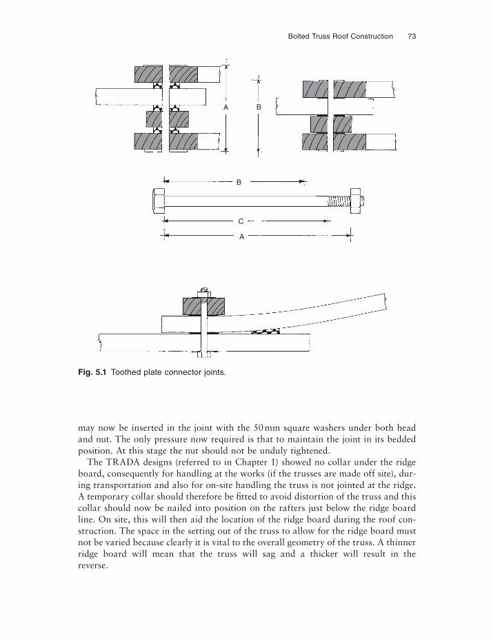
Bolted Truss Roof Construction 73
may now be inserted in the joint with the 50 mm square washers under both head and nut. The only pressure now required is that to maintain the joint in its bedded position. At this stage the nut should not be unduly tightened.
The TRADA designs (referred to in Chapter 1) showed no collar under the ridge board, consequently for handling at the works (if the trusses are made off site), dur-ing transportation and also for on-site handling the truss is not jointed at the ridge. A temporary collar should therefore be fi tted to avoid distortion of the truss and this collar should now be nailed into position on the rafters just below the ridge board line. On site, this will then aid the location of the ridge board during the roof con-struction. The space in the setting out of the truss to allow for the ridge board must not be varied because clearly it is vital to the overall geometry of the truss. A thinner ridge board will mean that the truss will sag and a thicker will result in the reverse.
Fig. 5.1 Toothed plate connector joints.
A
C
B
A B
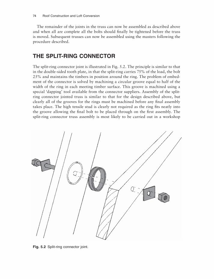
74 Roof Construction and Loft Conversion
The remainder of the joints in the truss can now be assembled as described above and when all are complete all the bolts should finally be tightened before the truss is moved. Subsequent trusses can now be assembled using the masters following the procedure described.
THE SPLIT-RING CONNECTOR
The split-ring connector joint is illustrated in Fig. 5.2. The principle is similar to that in the double-sided tooth plate, in that the split-ring carries 75% of the load, the bolt 25% and maintains the timbers in position around the ring. The problem of embed-ment of the connector is solved by machining a circular groove equal to half of the width of the ring in each meeting timber surface. This groove is machined using a special ‘dapping’ tool available from the connector suppliers. Assembly of the split-ring connector jointed truss is similar to that for the design described above, but clearly all of the grooves for the rings must be machined before any final assemblytakes place. The high tensile stud is clearly not required as the ring fits neatly into the groove allowing the final bolt to be placed through on the first assembly. The split-ring connector truss assembly is most likely to be carried out in a workshop
Fig. 5.2 Split-ring connector joint.
Bolted Truss Roof Construction 75
where the dapping procedure can be carried out in fi xed drilling jigs on benches. Dapping can be carried out on site but electric power to turn the dapper is almost essential, and a degree of skill is required in its accurate use. The bolt holes must be drilled first; the dapping tool is then located in the bolt hole to cut the groove for the connector.
Site assembly of bolt and connector jointed trusses using either connector form is of course a practical proposition, but factory assembly of the truss will generally re-sult in a more accurate component simply because of the equipment, level fl oor area, dry conditions and specialist operatives used in the construction.
ACCURACY
Most bolt and connector trusses for domestic roof construction will be assembled using sawn timber. The tolerance on sawn timber in terms of over and under sizing, particularly in the larger dimension, is significant and for this reason the full size setting-out of the truss has been recommended in the assembly procedures described. The precise location for the bolt centres is essential to maintain the design edge and end distance for the timber connectors themselves. Insuffi cient end distance may re-sult in a timber connector shearing out a section of timber thus allowing the truss joint to fail. Great care must therefore be taken to follow the precise dimensions de-tailed on the engineer’s drawing. Reference should be made in this respect to the di-mensions indicated on the design illustrated in Fig. 5.3.
STANDARD DESIGNS
The TRADA designs as stated earlier are no longer available, but the design principles are sound and all relevant metalwork and connectors are still available. Figure 5.3 is continued in this fourth edition by way of illustrating this typical bolt and connector truss but it must be emphasised that the illustration is not a current TRADA design.
Many homes built in the 1950s, 1960s and 1970s used this type of construction and it has proved to be a rugged durable roof structure. Similar roof trusses today would have to be engineered, but that done, purlins, common rafters and ceiling joists can all be ‘designed’ from building regulation span tables.
THE ROOF CONSTRUCTION
The bolt and connector truss is generally used as a principal truss with common rafters and ceiling ties supported from it and on the wall plate. The designs referred to above are spaced at 1.8 m centres with the design of the purlin, binders, plate and ridge being given on each individual sheet. A study should be made of the design sheet illustrated in Fig. 5.3.
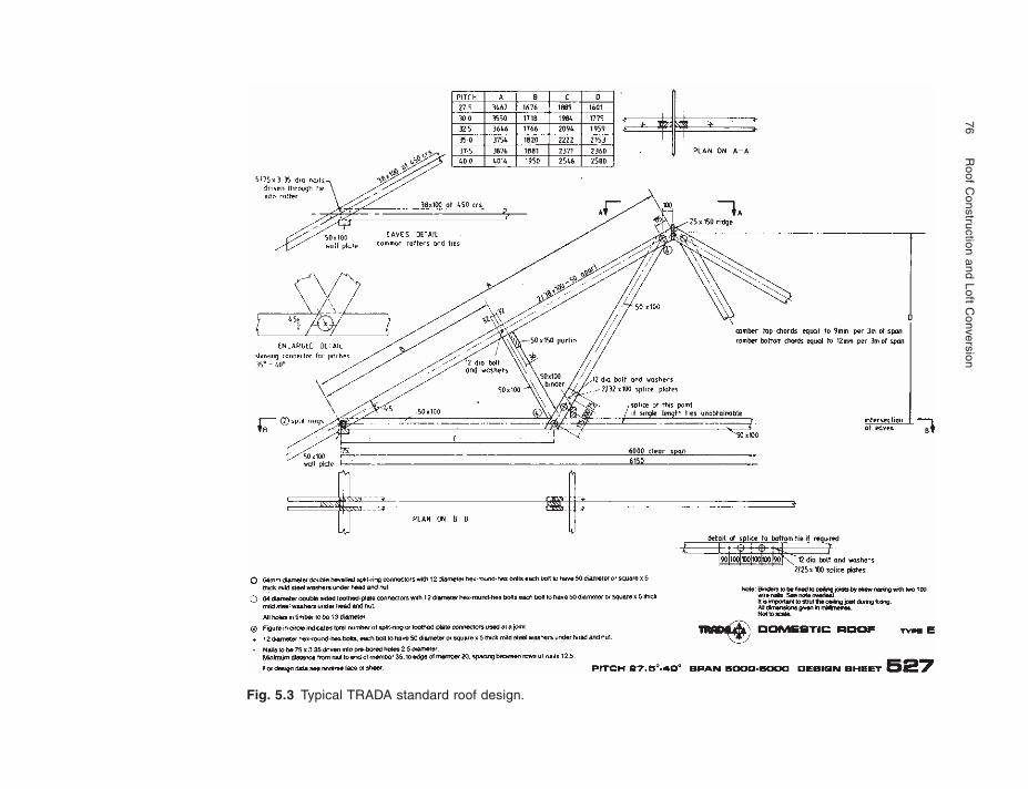
76
Roof C
onstruction and Loft Conversion
Fig. 5.3 Typical TRADA standard roof design.
Bolted Truss Roof Construction 77
The construction of the roof itself, once the principal trusses have been produced, is quite straightforward, with many of the joints being nailed as with the ‘traditional’ roof. The exception to this in some designs is the joint between ceiling joist and rafter, and on all designs where the ceiling tie cannot be obtained in one length, also the splice joint between the two lengths, which again uses a combination of connectors and nails. An alternative for the ceiling joist allows for it to be joined over a plate on a partition; this is not to be recommended where the construction process requires non-load bearing partitions to be installed after the roof is constructed. The roof should therefore be constructed wherever possible as an independent clear spanning structure between the two wall plates of the external walls. To avoid trusses inad-vertently bearing on internal non-load bearing partitions, it is good practice to have the roof tiled and therefore under normal working load conditions to allow any de-flection in the truss to take place before the partitions are fitted.
The trusses are not designed to carry water storage tank loads and thus, wherever possible, these should be directly supported from partitions below. If this is not practical then the advice of TRADA or the truss designer must be sought in order that the truss spacing may be reduced to carry the additional load. One final point on the standard roof assembly is that some difficulty may be experienced in nailing the ceiling joist tightly to its binder. A more effective connection is to use one of the readily available light galvanised metal cleats. These give a much more positive and stronger connection than traditional skew nailing. Figure 5.4 illustrates the roof construction described above.
BOLTED TRUSS HIPS
Hips can be formed using bolt and connector trussed structures, the hip usually be-ing supported on a ‘half’ truss, itself supported on one of the principals at hip peak and on the end wall plate at the hip eaves. A typical hip construction is illustrated in Fig. 5.5. The remainder of the hip timber members follow basically traditional construction techniques, described in Chapter 3. The hip rafter, however, generally carries the ends of the purlins and also supports the hanger, which in turn helps to span the binder from first principal to the end wall plate. It is essential that the ceil-ing tie member of the half truss used in the hip end is connected properly into the binder running on the centre line of the roof to ensure an adequate tie from one end of the roof to the other.
VALLEYS
Valley construction follows the design set out in Fig. 3.10, a principal truss being located on the ridge line of the intersecting roof in place of the double rafter illus-trated. With equal span and pitch intersecting roofs, purlin lines will coincide and they can be fixed together with a steel connector as indicated in Fig. 3.11. Unequal spans will mean a hanger from the higher to lower purlins and/or additional support
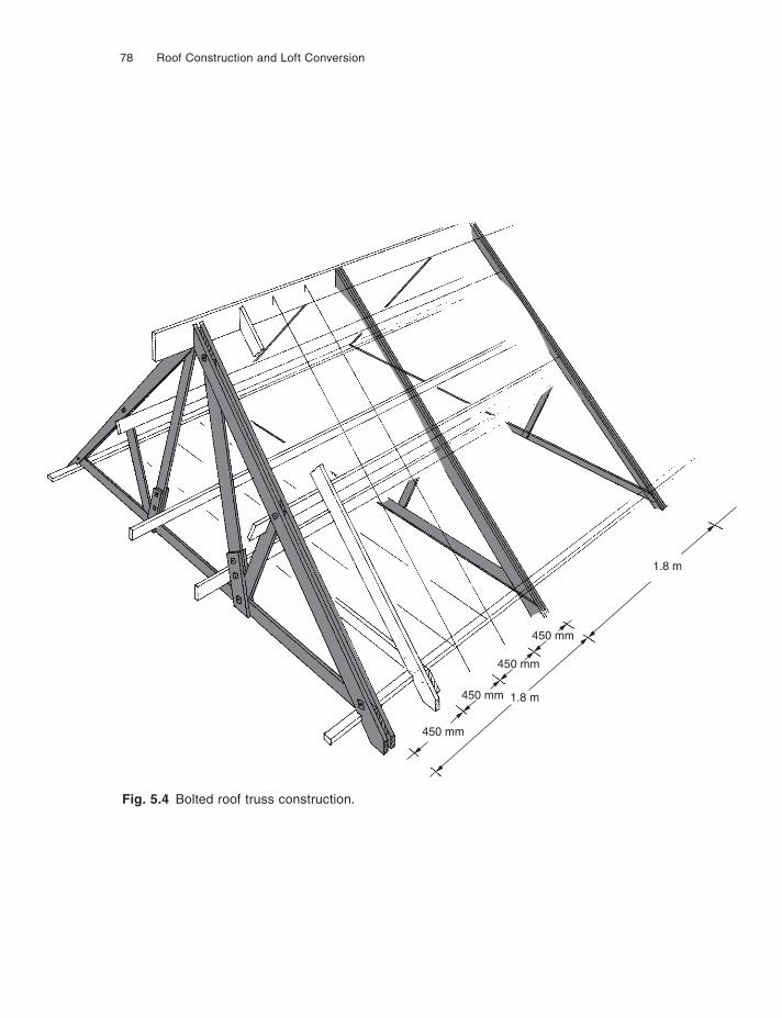
78 Roof Construction and Loft Conversion
Fig. 5.4 Bolted roof truss construction.
1.8 m
1.8 m
450 mm
450 mm
450 mm
450 mm
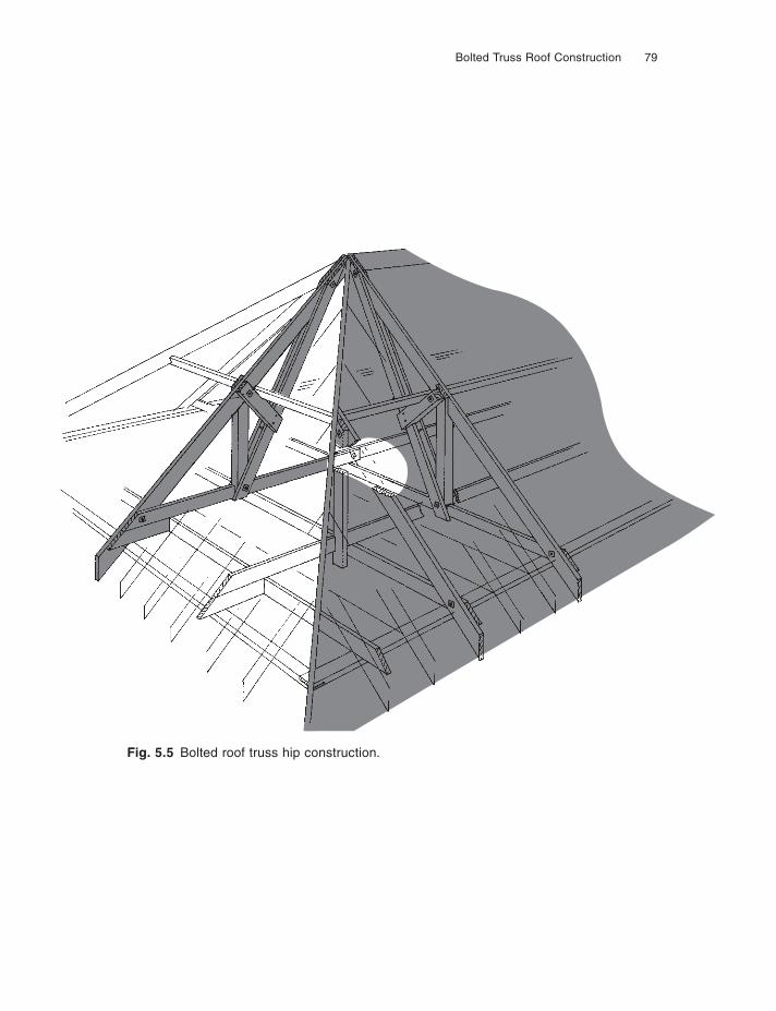
Bolted Truss Roof Construction 79
Fig. 5.5 Bolted roof truss hip construction.
80 Roof Construction and Loft Conversion
again as indicated in Fig. 3.11. Support may also be required for the main roof prin-cipal truss if there is no wall on the normal plate line. It is not generally possible to support this principal from the first principal truss of the intersecting roof unless it has been specifically designed to carry the additional load. It is more likely that a steel or timber beam must be employed within the roof space, using a special steel shoe designed to carry the end of the principal truss. Figure 5.6 illustrates this junc-tion. A beam beneath the truss is a more easily constructed detail, but its depth may restrict headroom below.
Care must be taken with this steel shoe design and the positioning of the support-ing beam, to allow adequate ‘end-distance’ for the rafter to ceiling joist connector discussed earlier. Also the positioning of the truss to shoe locating bolt should ideally be identical to the bolts used to assemble that particular joint. Assembly on site would then require temporary removal of one of the joint retaining bolts whilst the truss is temporarily supported. A slightly longer bolt is passed through the steel shoe and the truss to complete the joint.
Lighter weight steel standard hangers can be used to support rafter and ceiling joist, although the location of the supporting beam may be such that an extended length of support in the shoe similar to that used for trussed hangers may be required to give adequate bearing to the supported structure members.
STRUCTURAL OPENINGS
Dormer winders are unlikely to occur in a bolt and connector roof unless a specificattic design has been produced, in which case all openings will also have been struc-turally designed and these must be followed. Openings for chimneys and roof hatches will occur and these can generally be dealt with as illustrated in Fig. 3.18 or, in the case of small openings, as illustrated in Fig. 8.26. Care must be taken to position the principal trusses at design stage to avoid such openings.
ROOF STABILITY
The bolt and connector jointed principal roof truss construction, like most other forms, should not rely for its lateral stability upon the gable end wall structure. For this reason diagonal bracing on the undersides of the rafters should be provided and of course some temporary bracing will be required at construction stage to maintain the heavy principal trusses in position. Roof bracing is dealt with in more detail in Chapter 8.
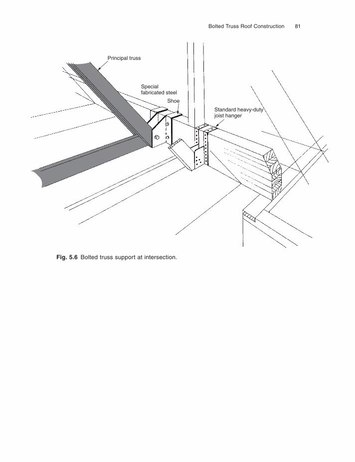
Bolted Truss Roof Construction 81
Fig. 5.6 Bolted truss support at intersection.
Principal truss
Specialfabricated steel
Shoe
Standard heavy-dutyjoist hanger
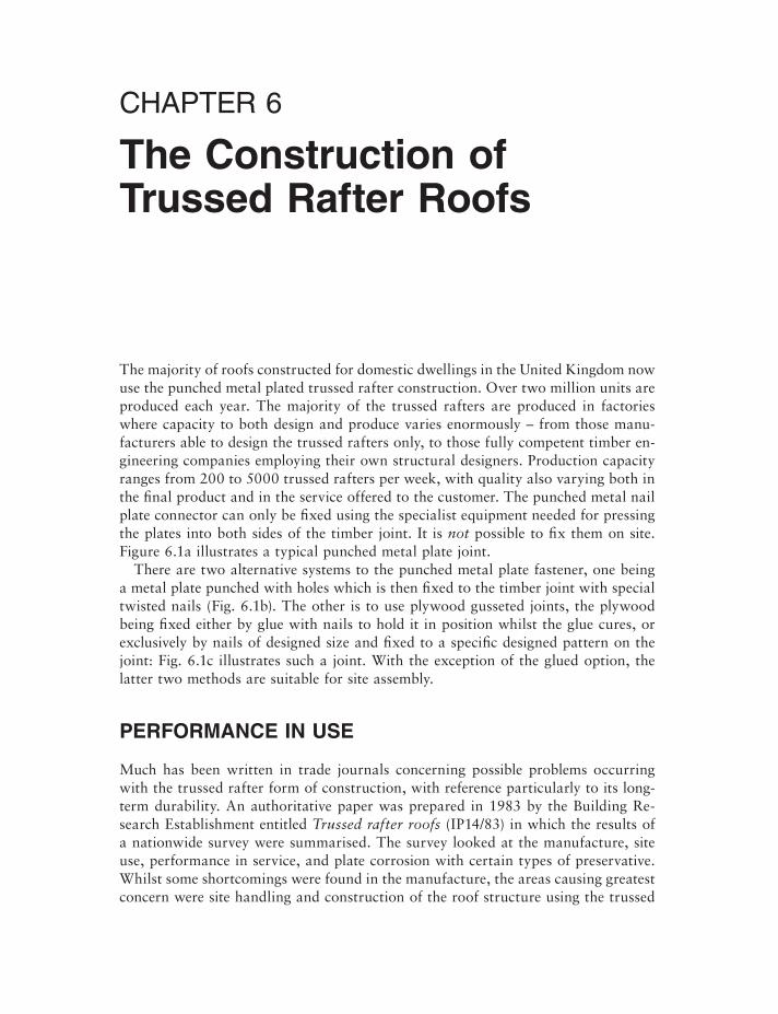
CHAPTER 6
The Construction of Trussed Rafter Roofs
The majority of roofs constructed for domestic dwellings in the United Kingdom now use the punched metal plated trussed rafter construction. Over two million units are produced each year. The majority of the trussed rafters are produced in factories where capacity to both design and produce varies enormously – from those manu-facturers able to design the trussed rafters only, to those fully competent timber en-gineering companies employing their own structural designers. Production capacity ranges from 200 to 5000 trussed rafters per week, with quality also varying both in the final product and in the service offered to the customer. The punched metal nail plate connector can only be fixed using the specialist equipment needed for pressing the plates into both sides of the timber joint. It is not possible to fix them on site. Figure 6.1a illustrates a typical punched metal plate joint.
There are two alternative systems to the punched metal plate fastener, one being a metal plate punched with holes which is then fixed to the timber joint with special twisted nails (Fig. 6.1b). The other is to use plywood gusseted joints, the plywood being fi xed either by glue with nails to hold it in position whilst the glue cures, or exclusively by nails of designed size and fixed to a specific designed pattern on the joint: Fig. 6.1c illustrates such a joint. With the exception of the glued option, the latter two methods are suitable for site assembly.
PERFORMANCE IN USE
Much has been written in trade journals concerning possible problems occurring with the trussed rafter form of construction, with reference particularly to its long-term durability. An authoritative paper was prepared in 1983 by the Building Re-search Establishment entitled Trussed rafter roofs (IP14/83) in which the results of a nationwide survey were summarised. The survey looked at the manufacture, site use, performance in service, and plate corrosion with certain types of preservative. Whilst some shortcomings were found in the manufacture, the areas causing greatest concern were site handling and construction of the roof structure using the trussed
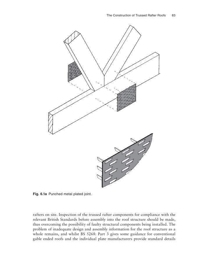
The Construction of Trussed Rafter Roofs 83
Fig. 6.1a Punched metal plated joint.
rafters on site. Inspection of the trussed rafter components for compliance with the relevant British Standards before assembly into the roof structure should be made, thus overcoming the possibility of faulty structural components being installed. The problem of inadequate design and assembly information for the roof structure as a whole remains, and whilst BS 5268: Part 3 gives some guidance for conventional gable ended roofs and the individual plate manufacturers provide standard details
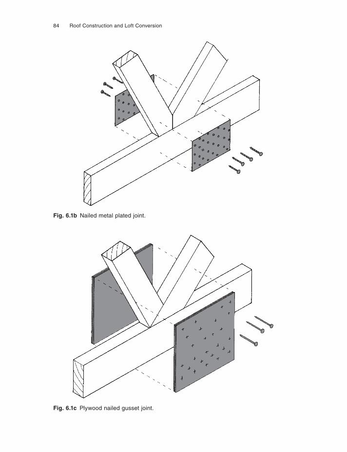
84 Roof Construction and Loft Conversion
Fig. 6.1b Nailed metal plated joint.
Fig. 6.1c Plywood nailed gusset joint.
The Construction of Trussed Rafter Roofs 85
for hips and valleys, the builder is not generally presented with a specific set of draw-ings for the assembly of the roof on which he is working. Increasingly the larger trussed rafter producers and the plate manufacturers are providing computer pro-grams which generate ‘whole roof’ designs. These designs not only include the layout of the trussed rafter itself, but all other infi ll timbers and support metalwork required for the structure. This considerably aids the correct site assembly of the roof structure.
This chapter concentrates on the construction of trussed rafter roofs including hips, valleys, attics and trimmed openings. The storage and handling of trussed rafters and other timber components, and the many ancillary details required to complete the roof are set out in Chapter 8.
DESIGN
The structural design, manufacture and some aspects of construction are dealt with in BS 5268: Part 3: 2002, Code of practice for trussed rafter roofs and reference will be made to this important document throughout this chapter. Whilst timber sizes may be obtained from safe span tables, the design of the joint plate or gusset mustbe provided by a qualifi ed structural engineer.
Most trussed rafter manufacturers use terminology not yet covered in previous chapters and the reader should refer to Fig. 6.2 for familiarisation with terms to be used throughout this chapter. The illustration shows a Fink truss, the most common configuration in use today. The geometry of this configuration can be found in Fig. 2.5. The standard spacing for trussed rafters is 600 mm, although 400 mm and 450 mm are not uncommon. Timber sizes are standardised throughout the United Kingdom, the timber being machined on all surfaces for accuracy in accordance with the standards set out in BS EN 1313/1. The timber is usually stress graded in accor-dance with BS 4978 and should be stamped with a grade mark. Whilst so called ‘nominal’ sizes are often quoted, i.e. 75, 87, 100, 125 and 150 × 38 mm, the fi nished section will be 72, 84, 97, 122 and 147 × 35 mm. Timber of 47 mm fi nished thickness is frequently used for attic trussed rafters with depths going up to 222 mm for heavily loaded rafters and fl oor joists. Trussed rafters in excess of 11 m span must use this thicker timber, or be made of multiple trusses of minimum 35 mm thickness, perma-nently fixed together by the truss manufacturer at works.
An understanding of the function of the trussed rafter is essential if good roof construction is to be achieved. The trussed rafter is designed to carry only the verti-cal loads imposed upon it, no lateral loads are catered for. The design assumes that the trussed rafter is maintained in its truly upright position by the various bracing and restraining members. Figure 6.2 illustrates this point. The wall plate, binders, tile battens and diagonal braces are all assumed in the structural design. All of these items have to be site fixed and it is essential therefore that the specification for these fixings is carried out. The load on the top chord is from self weight of the truss, the tiles, felt and battens plus statutory snow loading. On the bottom chord the load is from the self weight, ceiling and insulation plus a nominal loft loading and an
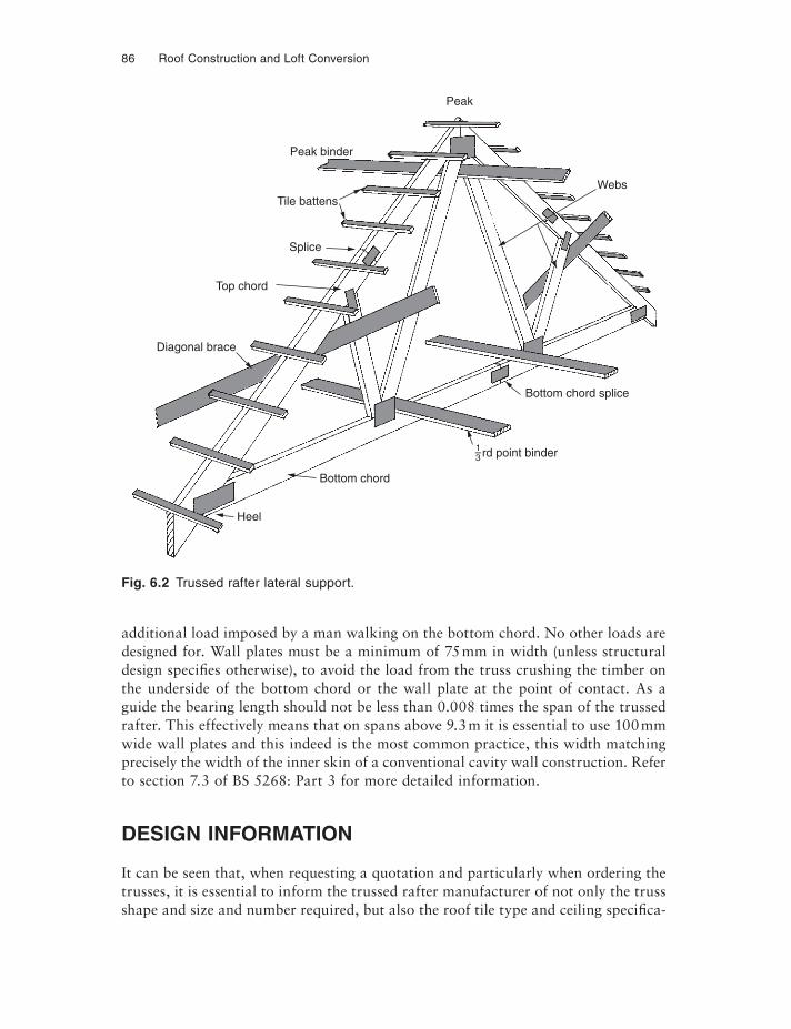
86 Roof Construction and Loft Conversion
additional load imposed by a man walking on the bottom chord. No other loads are designed for. Wall plates must be a minimum of 75 mm in width (unless structural design specifies otherwise), to avoid the load from the truss crushing the timber on the underside of the bottom chord or the wall plate at the point of contact. As a guide the bearing length should not be less than 0.008 times the span of the trussed rafter. This effectively means that on spans above 9.3 m it is essential to use 100 mm wide wall plates and this indeed is the most common practice, this width matching precisely the width of the inner skin of a conventional cavity wall construction. Refer to section 7.3 of BS 5268: Part 3 for more detailed information.
DESIGN INFORMATION
It can be seen that, when requesting a quotation and particularly when ordering the trusses, it is essential to inform the trussed rafter manufacturer of not only the truss shape and size and number required, but also the roof tile type and ceiling specifica-
Fig. 6.2 Trussed rafter lateral support.
Heel
Bottom chord
Bottom chord splice
Webs
Peak
Peak binder
Tile battens
Splice
Top chord
Diagonal brace
13–rd point binder
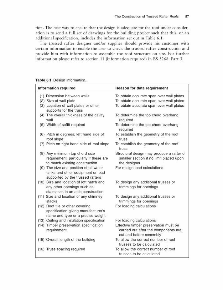
The Construction of Trussed Rafter Roofs 87
tion. The best way to ensure that the design is adequate for the roof under consider-ation is to send a full set of drawings for the building project such that this, or an additional specification, includes the information set out in Table 6.1.
The trussed rafter designer and/or supplier should provide his customer with certain information to enable the user to check the trussed rafter construction and provide him with information to assemble the roof structure on site. For further information please refer to section 11 (information required) in BS 5268: Part 3.
Table 6.1 Design information.
Information required Reason for data requirement
(1) Dimension between walls To obtain accurate span over wall plates(2) Size of wall plate To obtain accurate span over wall plates(3) Location of wall plates or other To obtain accurate span over wall plates
supports for the truss(4) The overall thickness of the cavity To determine the top chord overhang
wall required(5) Width of soffi t required To determine the top chord overhang
required(6) Pitch in degrees, left hand side of To establish the geometry of the roof
roof slope truss(7) Pitch on right hand side of roof slope To establish the geometry of the roof
truss(8) Any minimum top chord size Structural design may produce a rafter of
requirement, particularly if these are smaller section if no limit placed uponto match existing construction the designer
(9) The size and position of all water For design load calculationstanks and other equipment or loadsupported by the trussed rafters
(10) Size and location of loft hatch and To design any additional trusses orany other openings such as trimmings for openingsstaircases in an attic construction.
(11) Size and location of any chimney To design any additional trusses orstacks trimmings for openings
(12) Roof tile or other covering For loading calculationsspecifi cation giving manufacturer’sname and type or a precise weight
(13) Ceiling and insulation specifi cation For loading calculations(14) Timber preservation specifi cation Effective timber preservation must be
requirement carried out after the components are cut and before assembly(15) Overall length of the building To allow the correct number of roof trusses to be calculated(16) Truss spacing required To allow the correct number of roof trusses to be calculated
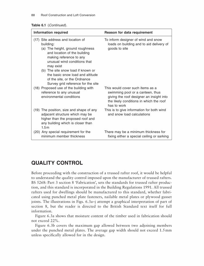
88 Roof Construction and Loft Conversion
QUALITY CONTROL
Before proceeding with the construction of a trussed rafter roof, it would be helpful to understand the quality control imposed upon the manufacturer of trussed rafters. BS 5268: Part 3 section 8 ‘Fabrication’, sets the standards for trussed rafter produc-tion, and this standard is incorporated in the Building Regulations 1991. All trussed rafters used for dwellings should be manufactured to this standard, whether fabri-cated using punched metal plate fasteners, nailable metal plates or plywood gusset joints. The illustrations in Figs. 6.3a–j attempt a graphical interpretation of part of section 8, but the reader is directed to the British Standard text itself for full information.
Figure 6.3a shows that moisture content of the timber used in fabrication should not exceed 22%.
Figure 6.3b covers the maximum gap allowed between two adjoining members under the punched metal plates. The average gap width should not exceed 1.5 mm unless specifically allowed for in the design.
Table 6.1 (Continued).
Information required Reason for data requirement
(17) Site address and location of To inform designer of wind and snowbuilding: loads on building and to aid delivery of(a) The height, ground roughness goods to site
and location of the buildingmaking reference to anyunusual wind conditions thatmay exist
(b) The site snow load if known orthe basic snow load and altitudeof the site, or the OrdnanceSurvey grid reference for the site
(18) Proposed use of the building with This would cover such items as areference to any unusual swimming pool or a canteen, thusenvironmental conditions giving the roof designer an insight into
the likely conditions in which the roof has to work(19) The position, size and shape of any This is to give information for both wind
adjacent structure which may be and snow load calculationshigher than the proposed roof andany building which is closer than1.5 m
(20) Any special requirement for the There may be a minimum thickness forminimum member thickness fi xing either a special ceiling or sarking
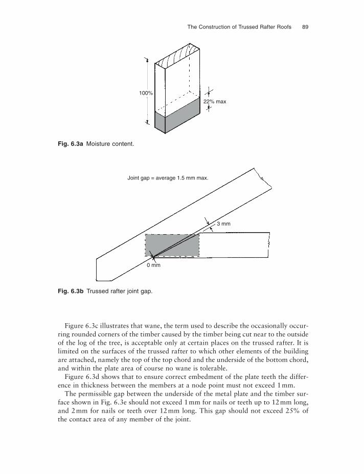
The Construction of Trussed Rafter Roofs 89
Figure 6.3c illustrates that wane, the term used to describe the occasionally occur-ring rounded corners of the timber caused by the timber being cut near to the outside of the log of the tree, is acceptable only at certain places on the trussed rafter. It is limited on the surfaces of the trussed rafter to which other elements of the building are attached, namely the top of the top chord and the underside of the bottom chord, and within the plate area of course no wane is tolerable.
Figure 6.3d shows that to ensure correct embedment of the plate teeth the differ-ence in thickness between the members at a node point must not exceed 1 mm.
The permissible gap between the underside of the metal plate and the timber sur-face shown in Fig. 6.3e should not exceed 1 mm for nails or teeth up to 12 mm long, and 2 mm for nails or teeth over 12 mm long. This gap should not exceed 25% of the contact area of any member of the joint.
Fig. 6.3a Moisture content.
Fig. 6.3b Trussed rafter joint gap.
22% max
100%
3 mm
Joint gap = average 1.5 mm max.
0 mm
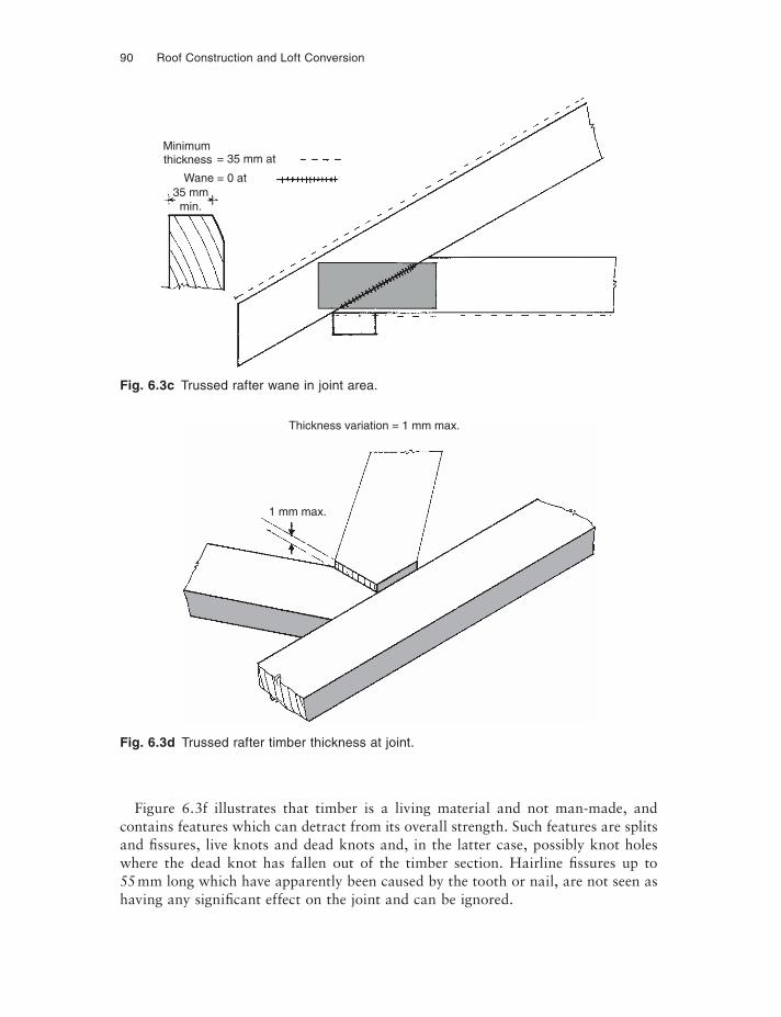
90 Roof Construction and Loft Conversion
Figure 6.3f illustrates that timber is a living material and not man-made, and contains features which can detract from its overall strength. Such features are splits and fi ssures, live knots and dead knots and, in the latter case, possibly knot holes where the dead knot has fallen out of the timber section. Hairline fi ssures up to 55 mm long which have apparently been caused by the tooth or nail, are not seen as having any significant effect on the joint and can be ignored.
Thickness variation = 1 mm max.
1 mm max.
Fig. 6.3c Trussed rafter wane in joint area.
Fig. 6.3d Trussed rafter timber thickness at joint.
Minimumthickness = 35 mm at
Wane = 0 at35 mm
min.
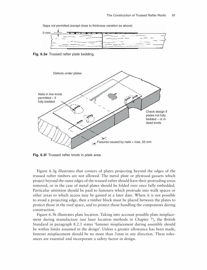
The Construction of Trussed Rafter Roofs 91
Figure 6.3g illustrates that corners of plates projecting beyond the edges of the trussed rafter timbers are not allowed. The metal plate or plywood gussets which project beyond the outer edges of the trussed rafter should have their protruding areas removed, or in the case of metal plates should be folded over once fully embedded. Particular attention should be paid to fasteners which protrude into walk spaces or other areas to which access may be gained at a later date. Where it is not possible to avoid a projecting edge, then a timber block must be placed between the plates to protect those in the roof space, and to protect those handling the components during construction.
Figure 6.3h illustrates plate location. Taking into account possible plate misplace-ment during manufacture (see laser location methods in Chapter 7), the British Standard in paragraph 8.2.1 states ‘fastener misplacement during assembly should be within limits assumed in the design’. Unless a greater allowance has been made, fastener misplacement should be no more than 5 mm in any direction. These toler-ances are essential and incorporate a safety factor in design.
0 mm
Gaps not permitted (except close to thickness variation as above)
Fig. 6.3e Trussed rafter plate bedding.
Fig. 6.3f Trussed rafter knots in plate area.
Nails in live knotspermitted – iffully bedded
Defects under plates
Fissures caused by nails = max. 55 mm
Check design ifplates not fullybedded – or in dead knots
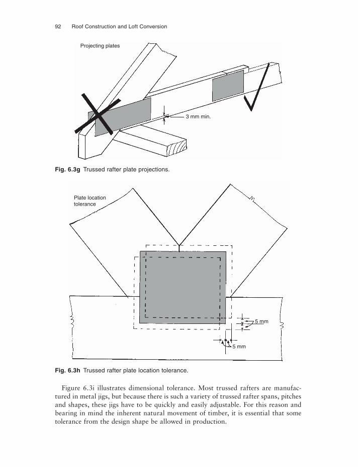
92 Roof Construction and Loft Conversion
Figure 6.3i illustrates dimensional tolerance. Most trussed rafters are manufac-tured in metal jigs, but because there is such a variety of trussed rafter spans, pitches and shapes, these jigs have to be quickly and easily adjustable. For this reason and bearing in mind the inherent natural movement of timber, it is essential that some tolerance from the design shape be allowed in production.
3 mm min.
Projecting plates
5 mm
Plate locationtolerance
5 mm
Fig. 6.3g Trussed rafter plate projections.
Fig. 6.3h Trussed rafter plate location tolerance.
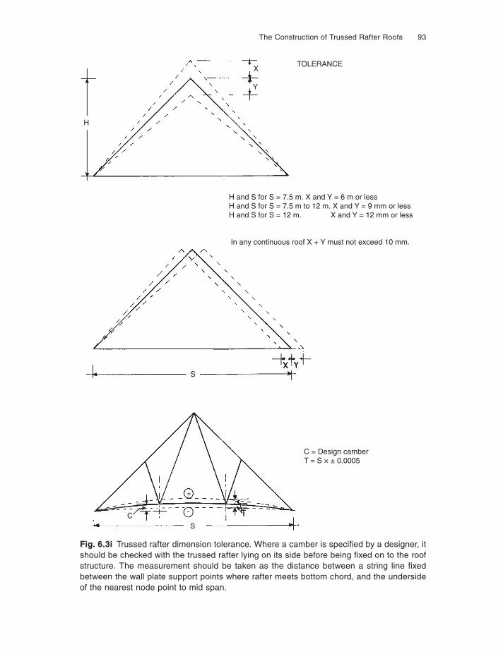
The Construction of Trussed Rafter Roofs 93
Fig. 6.3i Trussed rafter dimension tolerance. Where a camber is specifi ed by a designer, it should be checked with the trussed rafter lying on its side before being fi xed on to the roof structure. The measurement should be taken as the distance between a string line fi xed between the wall plate support points where rafter meets bottom chord, and the underside of the nearest node point to mid span.
TOLERANCEX
Y
H
H and S for S = 7.5 m. X and Y = 6 m or lessH and S for S = 7.5 m to 12 m. X and Y = 9 mm or lessH and S for S = 12 m. X and Y = 12 mm or less
In any continuous roof X + Y must not exceed 10 mm.
SX Y
+
-
SC
94 Roof Construction and Loft Conversion
Figure 6.3j illustrates a marked trussed rafter. Until the publication of BS 5268: Part 3 it was not necessary to mark the trussed rafter with the name of the company responsible for its manufacture. This has changed, with the requirement of the 1998 edition of the standard in section 8 ‘fabrication’ in paragraph 8.1, under the heading ‘marking’, which requires that every trussed rafter should be clearly marked with the identifi cation of the producer, the materials used and the standard to which it is produced. Furthermore the marking label or stamp should be placed as near to the apex as possible thus making it clearly visible in the completed roof void. Whilst it may be easier in manufacture to mark the truss near the wall plate support junction or on the bottom chord, this area is invariably covered with insulation and should anything go wrong at a later date with the roof structure then the vital information would be difficult to find.
INSPECTION AND QUALITY ASSURANCE
The mandatory requirements for QA of timber products including trussed rafters, like many other commodities we buy from fridges to furniture, are now progressively coming under the harmonisation standards of the European Community. As has been seen in Chapter 1, the standards for design are in a state of fl ux, and this is also true for those standards relating to quality assurance. CE (from the French Conformité Européan) is the ultimate goal, but whilst most European countries have adopted this, the UK, Ireland, Portugal and Sweden have not. Compliance with CPD (Con-struction Products Directive) is however mandatory, and this has been enacted in the
TRUSS MANUFACTURED INACCORDANCE WITH BS 5268 (2 & 3)
EUROPEAN RED/WHITEWOODGRADED AS MARKEDAND MANUFACTURED
IN ACCORDANCE WITH EN1059
SCOTTS OF THRAPSTON LTD.BRIDGE STREET, THRAPSTON,
NORTHAMPTONSHIRE NN144LRTEL: (01832)732366
Fig. 6.3j Trussed rafter marking.
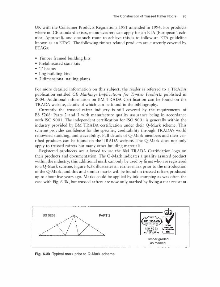
The Construction of Trussed Rafter Roofs 95
UK with the Consumer Products Regulations 1991 amended in 1994. For products where no CE standard exists, manufacturers can apply for an ETA (European Tech-nical Approval), and one such route to achieve this is to follow an ETA guideline known as an ETAG. The following timber related products are currently covered by ETAGs:
• Timber framed building kits• Prefabricated stair kits• ‘I’ beams• Log building kits• 3 dimensional nailing plates
For more detailed information on this subject, the reader is referred to a TRADA publication entitled CE Marking: Implications for Timber Products published in 2004. Additional information on BM TRADA Certification can be found on the TRADA website, details of which can be found in the bibliography.
Currently the trussed rafter industry is still covered by the requirements of BS 5268: Parts 2 and 3 with manufacture quality assurance being in accordance with ISO 9001. The independent certification for ISO 9001 is generally within the industry provided by BM TRADA certification under their Q-Mark scheme. This scheme provides confi dence for the specifi er, creditability through TRADA’s world renowned standing, and traceability. Full details of Q-Mark members and their cer-tifi ed products can be found on the TRADA website. The Q-Mark does not only apply to trussed rafters but many other building materials.
Registered producers are allowed to use the BM TRADA Certification logo on their products and documentation. The Q-Mark indicates a quality assured product within the industry; this additional mark can only be used by fi rms who are registered to a Q-Mark scheme. Figure 6.3k illustrates an earlier mark prior to the introduction of the Q-Mark, and this and similar marks will be found on trussed rafters produced up to about fi ve years ago. Marks could be applied by ink stamping as was often the case with Fig. 6.3k, but trussed rafters are now only marked by fixing a tear resistant
Fig. 6.3k Typical mark prior to Q-Mark scheme.
BS 5268 PART 3
Timber gradedas marked
96 Roof Construction and Loft Conversion
plastic label under the peak plate on each trussed rafter (Fig. 6.3j); this entrapment under the metal plate ensures that it is not easily detached.
The BM TRADA scheme sets down standards incorporating those in BS 5268: Part 3 and ISO 9001. It also now incorporates BS EN 14250 and a new identification label is now beginning to appear on the product. Whilst there are some modifications to the requirements compared to those printed on the preceding pages, the only ones concerning the end user are found in clause 5 under the heading ‘Product Require-ments’. Sub-clause 5.1, for instance, specifi es strength and stiffness, 5.2 states that a reaction to fire shall be declared, 5.3 dealing with structural members, states that a depth of external members must not be less than 68 mm, and that dimensional accuracy shall be as follows:
• Up to 10 m not more than 20 mm• More than 10 m = 2 mm for each metre
Sub-clause 5.4 on joints, the fastener position, states that misplacement must be not greater than 10 mm.
NB: This limit has to be taken account of in the structural design and may vary from system design and requirement with consequent impact on plate size. Again if the reader requires further information reference should be made to the full British Standard.
In summary, as this book goes to press, most trussed rafter manufacturers are using the BM TRADA Q-Mark scheme, and will be marking trusses as illus-trated in Fig. 6.3l. This will slowly be moved to a new label which will incorporate BS EN 14250, and ultimately probably through TRADA certification, the product will be CE marked.
THE CONSTRUCTION OF A TRUSSED RAFTER ROOF
Guidelines to the correct handling and storage of timber and timber components are to be found in Chapter 8.
Fig. 6.3l Q-Mark incorporating BS EN 14250.
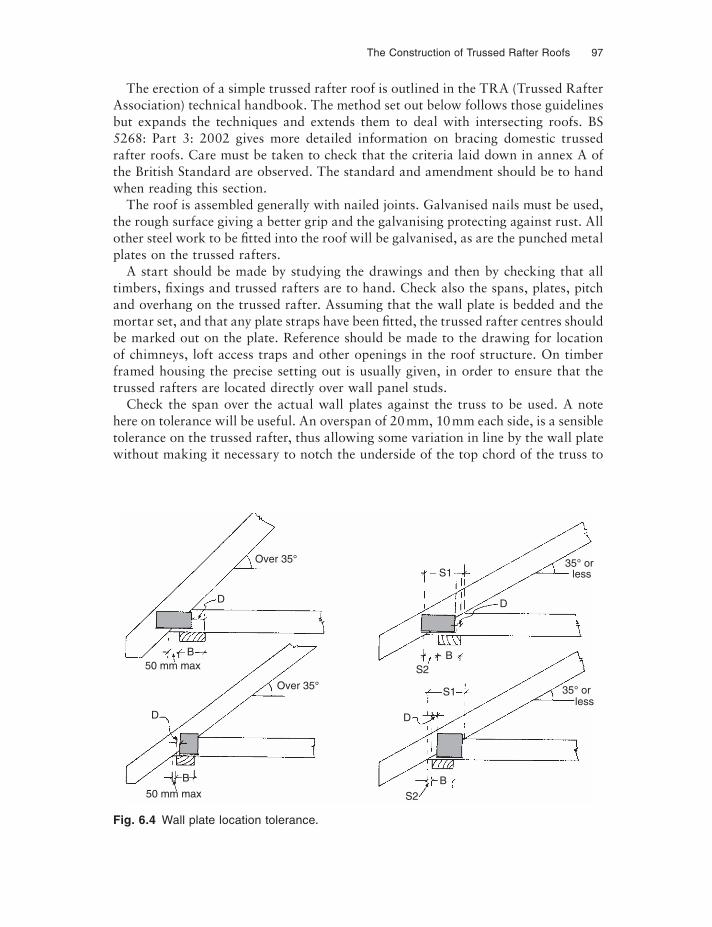
The Construction of Trussed Rafter Roofs 97
The erection of a simple trussed rafter roof is outlined in the TRA (Trussed Rafter Association) technical handbook. The method set out below follows those guidelines but expands the techniques and extends them to deal with intersecting roofs. BS 5268: Part 3: 2002 gives more detailed information on bracing domestic trussed rafter roofs. Care must be taken to check that the criteria laid down in annex A of the British Standard are observed. The standard and amendment should be to hand when reading this section.
The roof is assembled generally with nailed joints. Galvanised nails must be used, the rough surface giving a better grip and the galvanising protecting against rust. All other steel work to be fi tted into the roof will be galvanised, as are the punched metal plates on the trussed rafters.
A start should be made by studying the drawings and then by checking that all timbers, fixings and trussed rafters are to hand. Check also the spans, plates, pitch and overhang on the trussed rafter. Assuming that the wall plate is bedded and the mortar set, and that any plate straps have been fi tted, the trussed rafter centres should be marked out on the plate. Reference should be made to the drawing for location of chimneys, loft access traps and other openings in the roof structure. On timber framed housing the precise setting out is usually given, in order to ensure that the trussed rafters are located directly over wall panel studs.
Check the span over the actual wall plates against the truss to be used. A note here on tolerance will be useful. An overspan of 20 mm, 10 mm each side, is a sensible tolerance on the trussed rafter, thus allowing some variation in line by the wall plate without making it necessary to notch the underside of the top chord of the truss to
B50 mm max
Over 35°
50 mm max
B
S2
B
D
less35° orS1
BS2
S1
D
less35° orOver 35°
D
D
Fig. 6.4 Wall plate location tolerance.
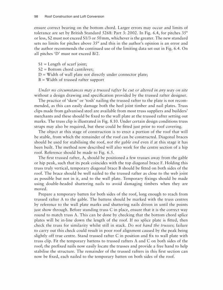
98 Roof Construction and Loft Conversion
ensure correct bearing on the bottom chord. Larger errors may occur and limits of tolerance are set by British Standard 5268: Part 3: 2002. In Fig. 6.4, for pitches 35° or less, S2 must not exceed S1/3 or 50 mm, whichever is the greater. The new standard sets no limits for pitches above 35° and this in the author’s opinion is an error and the author recommends the continued use of the limiting data set out in Fig. 6.4. On all pitches ‘D’ must not exceed B/2.
S1 = Length of scarf joint;S2 = Bottom chord cantilever;D = Width of wall plate not directly under connector plate;B = Width of trussed rafter support
Under no circumstances may a trussed rafter be cut or altered in any way on site without a design drawing and specification provided by the trussed rafter designer.
The practice of ‘skew’ or ‘tosh’ nailing the trussed rafter to the plate is not recom-mended, as this can easily damage both the heel joint timber and nail plates. Truss clips made from galvanised steel are available from most truss suppliers and builders’ merchants and these should be fixed to the wall plate at the trussed rafter setting out marks. The truss clip is illustrated in Fig. 8.10. Under certain design conditions truss straps may also be required, but these could be fitted just prior to roof covering.
The object at this stage of construction is to erect a portion of the roof that will be stable, from which the remainder of the roof can be constructed. Diagonal braces should be used for stabilising the roof, not the gable end even if at this stage it has been built. The method now described will also work for the centre section of a hip roof. Reference should be made to Fig. 6.5.
The first trussed rafter, A, should be positioned a few trusses away from the gable or hip peak, such that its peak coincides with the top diagonal brace F. Holding this truss truly vertical, temporary diagonal brace B should be fi tted on both sides of the roof. The brace should be well nailed to the trussed rafter as close to the web joint as possible but not in it, and to the wall plate. Temporary fixings should be made using double-headed shuttering nails to avoid damaging timbers when they are moved.
Prepare a temporary batten for both sides of the roof, long enough to reach from trussed rafter A to the gable. The battens should be marked with the truss centres by reference to the wall plate marks and shuttering nails driven in until the points just show through. Before standing truss C in place, ensure that it is the correct way round to match truss A. This can be done by checking that the bottom chord splice plates will be in-line down the length of the roof. If no splice plate is fi tted, then check the truss for similarity whilst still in stack. Do not hand the trusses; failure to carry out this check could result in poor roof alignment caused by the peak being slightly off true centre. Stand trussed rafter C in position and fix to wall plate with truss clip. Fit the temporary battens to trussed rafters A and C on both sides of the roof; the prefixed nails now easily locate the trusses and provide a free hand to help stabilise the structure. The remainder of the trussed rafters in this first section can now be fixed, each nailed to the temporary batten on both sides of the roof.
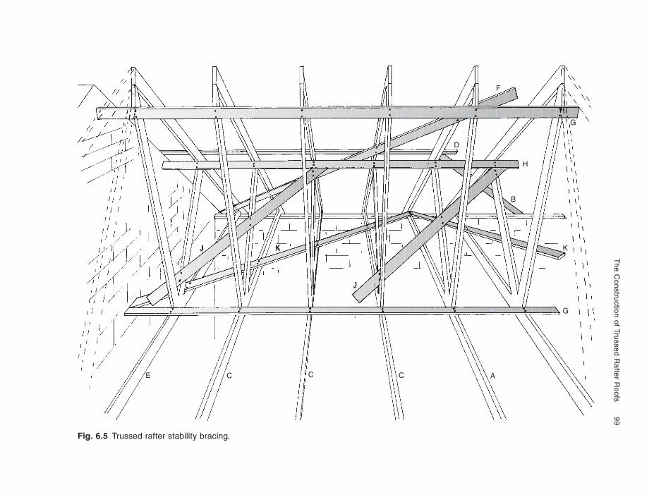
The C
onstruction of Trussed Rafter R
oofs
99
Fig. 6.5 Trussed rafter stability bracing.
J K
J
B
H
D
G
F
E C C C A
G
K
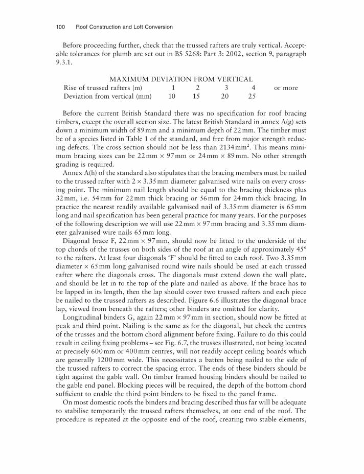
100 Roof Construction and Loft Conversion
Before proceeding further, check that the trussed rafters are truly vertical. Accept-able tolerances for plumb are set out in BS 5268: Part 3: 2002, section 9, paragraph 9.3.1.
MAXIMUM DEVIATION FROM VERTICALRise of trussed rafters (m) 1 2 3 4 or moreDeviation from vertical (mm) 10 15 20 25
Before the current British Standard there was no specification for roof bracing timbers, except the overall section size. The latest British Standard in annex A(g) sets down a minimum width of 89 mm and a minimum depth of 22 mm. The timber must be of a species listed in Table 1 of the standard, and free from major strength reduc-ing defects. The cross section should not be less than 2134 mm2. This means mini-mum bracing sizes can be 22 mm × 97 mm or 24 mm × 89 mm. No other strength grading is required.
Annex A(h) of the standard also stipulates that the bracing members must be nailed to the trussed rafter with 2 × 3.35 mm diameter galvanised wire nails on every cross-ing point. The minimum nail length should be equal to the bracing thickness plus 32 mm, i.e. 54mm for 22 mm thick bracing or 56 mm for 24 mm thick bracing. In practice the nearest readily available galvanised nail of 3.35 mm diameter is 65 mm long and nail specification has been general practice for many years. For the purposes of the following description we will use 22 mm × 97 mm bracing and 3.35 mm diam-eter galvanised wire nails 65 mm long.
Diagonal brace F, 22 mm × 97 mm, should now be fi tted to the underside of the top chords of the trusses on both sides of the roof at an angle of approximately 45° to the rafters. At least four diagonals ‘F’ should be fi tted to each roof. Two 3.35 mm diameter × 65 mm long galvanised round wire nails should be used at each trussed rafter where the diagonals cross. The diagonals must extend down the wall plate, and should be let in to the top of the plate and nailed as above. If the brace has to be lapped in its length, then the lap should cover two trussed rafters and each piece be nailed to the trussed rafters as described. Figure 6.6 illustrates the diagonal brace lap, viewed from beneath the rafters; other binders are omitted for clarity.
Longitudinal binders G, again 22 mm × 97 mm in section, should now be fitted at peak and third point. Nailing is the same as for the diagonal, but check the centres of the trusses and the bottom chord alignment before fixing. Failure to do this could result in ceiling fixing problems – see Fig. 6.7, the trusses illustrated, not being located at precisely 600 mm or 400 mm centres, will not readily accept ceiling boards which are generally 1200 mm wide. This necessitates a batten being nailed to the side of the trussed rafters to correct the spacing error. The ends of these binders should be tight against the gable wall. On timber framed housing binders should be nailed to the gable end panel. Blocking pieces will be required, the depth of the bottom chord suffi cient to enable the third point binders to be fixed to the panel frame.
On most domestic roofs the binders and bracing described thus far will be adequate to stabilise temporarily the trussed rafters themselves, at one end of the roof. The procedure is repeated at the opposite end of the roof, creating two stable elements,
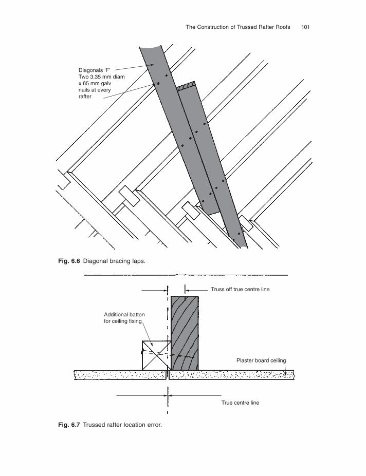
The Construction of Trussed Rafter Roofs 101
Fig. 6.6 Diagonal bracing laps.
Fig. 6.7 Trussed rafter location error.
Diagonals ‘F’Two 3.35 mm diamx 65 mm galvnails at everyrafter
Additional battenfor ceiling fixing
Plaster board ceiling
True centre line
Truss off true centre line
102 Roof Construction and Loft Conversion
and finally the centre section is fi lled in, taking care to lap the longitudinal G over two trussed rafters.
The roof structure has to absorb the load from wind blowing on the gable ends, causing pressure at one end and suction at the other. BS 5268: Part 3, appendix A gives standard bracing, provided certain conditions of wind speed, pitch and span are not exceeded. Specification must therefore be checked before proceeding.
Continuing with the construction, it will be assumed that the standard wind brac-ing is satisfactory. At least four diagonal bracers F must be fitted at approximately 45° to form ‘X’ formations down the whole length of the building. The longitudinal binder H should be fi tted, timber section and nailing as before, from one gable to the other, lapping as required. Fit this to both slopes of the roof close to the web on top chord joints. Diagonals J should now be fi tted to the short webs, but only on trusses greater than 8 m span. Although not critical, the direction of slope should be from the bottom chord at the gable to the top chord; the slope will reverse at the centre line of the building. Finally, diagonal K should be fi tted on top of the bottom chords; these should be placed at approximately 45° to the bottom chords and pro-duce a ‘W’ formation from one gable to the other. Diagonal ‘K’ is not a requirement of BS 5268: Part 3: 1998, but in the author’s opinion is advisable. Annex A of the British Standard recognises the lack of lateral stiffness of house supporting walls exceeding 9 m long between buttressing, and restricts its bracing information accord-ingly. Many houses at construction stage have walls on which trusses are supported with no buttressing from internal partitions, and are no more than a series of slender columns of cavity brickwork connected only by steel or concrete lintels. At roof construction and tiling stage the roof does not have the benefi t of the plasterboard ceiling diaphragm. In timber framed housing brace K is essential.
The roof is now capable of withstanding the wind loads placed upon it, but the gable walls are not connected to it. On the pressure side the wall would be blown onto the roof and would probably be secure, provided the blocking had been fixed between the wall and the first truss, and between the first and second trusses (see Fig. 8.18). On the suction side, the wall would be sucked out. The gable walls must therefore be fixed securely into the roof structure with metal straps. These gable restraint straps apply to all forms of roof construction and are therefore detailed in Chapter 8 under a separate heading. British Standard 5268: Part 3, appendix B gives an appropriate standard for trussed roofs. Details of strapping roofs to walls are also given in Approved Document A of the 1991 Building Regulations, in the NHBC chapter 7.2 ‘pitched roofs’ and in the Trussed Rafter Association technical leaflet.
To complete the roof structure, gable ladders, water tank platform, barge, fascia, soffit,ventilators and eaves insulation controllers must be fitted. These items are dealt with in detail in Chapter 8. In addition to the bracing A–K described above, some extra bracing may be required by the truss designer, to prevent compression buckling of long web members. This additional bracing will take the form of more rows of brace H, but fitted at the centre of the web length. These bracing rows also require a locking brace (as J), fi tted to the opposite face of the web at approximately 6.0 m centres.
The Construction of Trussed Rafter Roofs 103
HIP END ROOFS
The construction of trussed rafter hip end roofs varies from one truss system to an-other. Precise construction details are therefore given in Chapter 7 under each plate manufacturer’s heading.
On roofs less than 5 m span almost traditional hip construction may be used, as detailed in Chapter 3. In excess of this span most systems use prefabricated hip trusses with, in some cases, only the extreme lower corners of the hip being of site cut and fi tted construction. More details of the variation between trussed rafter manufacturers’ hip construction are given in Chapter 7.
Rafter diagonal bracing is not generally required in a hip roof, the hip itself being a rigid diagonal structure. Longitudinal binders G must be continued from the main roof into the hip construction, plus additional binders H fixed flat on top of the hip trusses’ top chords. Diagonal K should be installed (see Fig. 6.5).
Most trussed rafter hip constructions involve a compound girder assembled from two, three or in some cases four individual trussed rafters. The nailing together of these individual components to form a girder is critical, and should be carried out by the trussed rafter manufacturer at works. If girders are not nailed by the manu-facturer then a nailing and bolting detail must be provided by the roof designer. When fastened together on site, bolts must be used for the bottom chord members, in positions marked by the truss manufacturer. In all cases the nails and bolts must be positioned strictly in accordance with the manufacturer’s instructions. See a typi-cal nailing and bolting pattern given in Fig. 6.10a. The setting out of the girder and intermediate trussed rafters is also critical and dimensions given on drawings must be carefully followed.
VALLEYS AND INTERSECTING ROOFS
The construction of valleys on trussed rafter roofs varies little between plate systems, most using a set of reducing trusses imposed upon the main roof structure. The designs are however dealt with separately under each system heading in Chapter 7.
Complex intersections normally have special design drawings supplied for them by the trussed rafter manufacturer. The solutions follow a pattern and typical details are given below. Firstly, Fig. 6.8 illustrates the construction of a roof intersection on which the main roof cannot be supported on a wall or beam, but is instead supported on a girder or compound truss. Secondly, in Fig. 6.11, a further complication is caused by a hip occurring at the intersection.
The location of the girder truss must be such that it will carry the main roof stan-dard truss, the overhang of the standard trussed rafters simply being removed on site if special trusses have not been provided. If the overhang is removed on site, care must be taken not to cut too near the heel joint plate: a minimum distance of 10 mm is recommended. See Fig. 6.9 for the girder to standard truss detail.
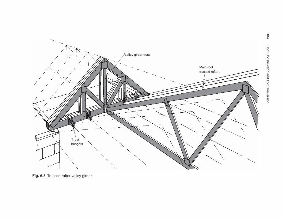
104
R
oof Construction and Loft C
onversion
Fig. 6.8 Trussed rafter valley girder.
Valley girder truss
Trusshangers
Main rooftrussed rafters
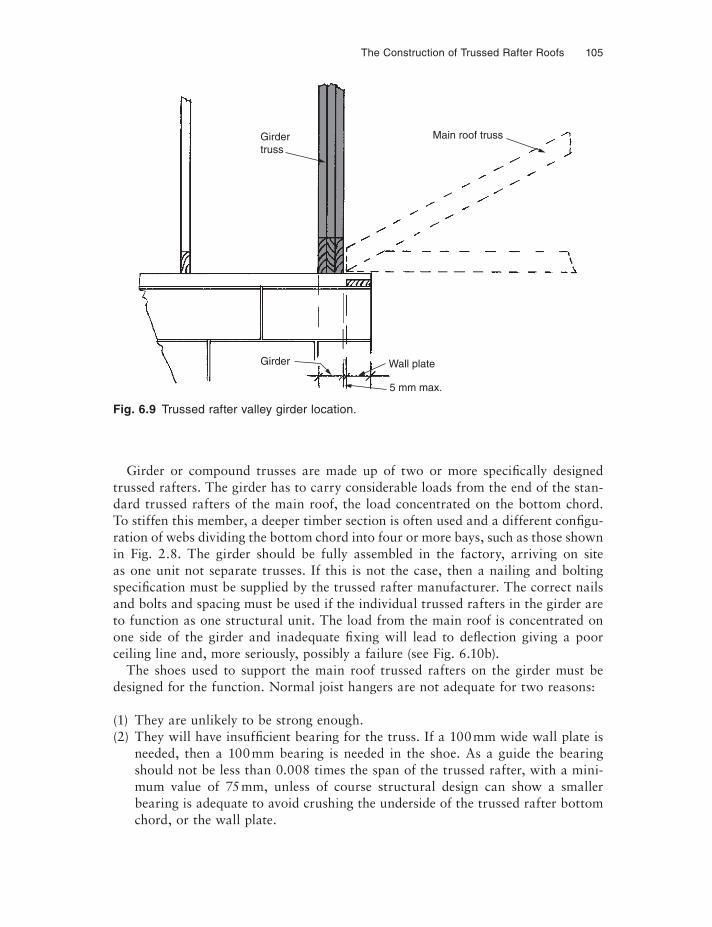
The Construction of Trussed Rafter Roofs 105
Girder or compound trusses are made up of two or more specifically designed trussed rafters. The girder has to carry considerable loads from the end of the stan-dard trussed rafters of the main roof, the load concentrated on the bottom chord. To stiffen this member, a deeper timber section is often used and a different configu-ration of webs dividing the bottom chord into four or more bays, such as those shown in Fig. 2.8. The girder should be fully assembled in the factory, arriving on site as one unit not separate trusses. If this is not the case, then a nailing and bolting specification must be supplied by the trussed rafter manufacturer. The correct nails and bolts and spacing must be used if the individual trussed rafters in the girder are to function as one structural unit. The load from the main roof is concentrated on one side of the girder and inadequate fi xing will lead to deflection giving a poor ceiling line and, more seriously, possibly a failure (see Fig. 6.10b).
The shoes used to support the main roof trussed rafters on the girder must be designed for the function. Normal joist hangers are not adequate for two reasons:
(1) They are unlikely to be strong enough.(2) They will have insuffi cient bearing for the truss. If a 100 mm wide wall plate is
needed, then a 100 mm bearing is needed in the shoe. As a guide the bearing should not be less than 0.008 times the span of the trussed rafter, with a mini-mum value of 75 mm, unless of course structural design can show a smaller bearing is adequate to avoid crushing the underside of the trussed rafter bottom chord, or the wall plate.
Fig. 6.9 Trussed rafter valley girder location.
Girdertruss
Girder
Main roof truss
Wall plate
5 mm max.
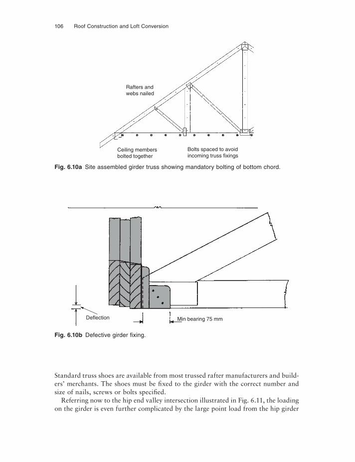
106 Roof Construction and Loft Conversion
Fig. 6.10a Site assembled girder truss showing mandatory bolting of bottom chord.
Rafters andwebs nailed
Ceiling membersbolted together
Bolts spaced to avoidincoming truss fixings
Fig. 6.10b Defective girder fi xing.
Deflection Min bearing 75 mm
Standard truss shoes are available from most trussed rafter manufacturers and build-ers’ merchants. The shoes must be fixed to the girder with the correct number and size of nails, screws or bolts specifi ed.
Referring now to the hip end valley intersection illustrated in Fig. 6.11, the loading on the girder is even further complicated by the large point load from the hip girder
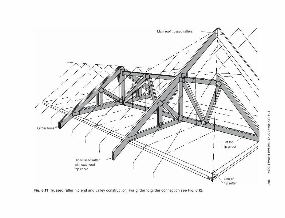
The C
onstruction of Trussed Rafter R
oofs 107
Fig. 6.11 Trussed rafter hip end and valley construction. For girder to girder connection see Fig. 6.12.
Main roof trussed rafters
Girder truss
Hip trussed rafterwith extendedtop chord
Flat tophip girder
Line ofhip rafter
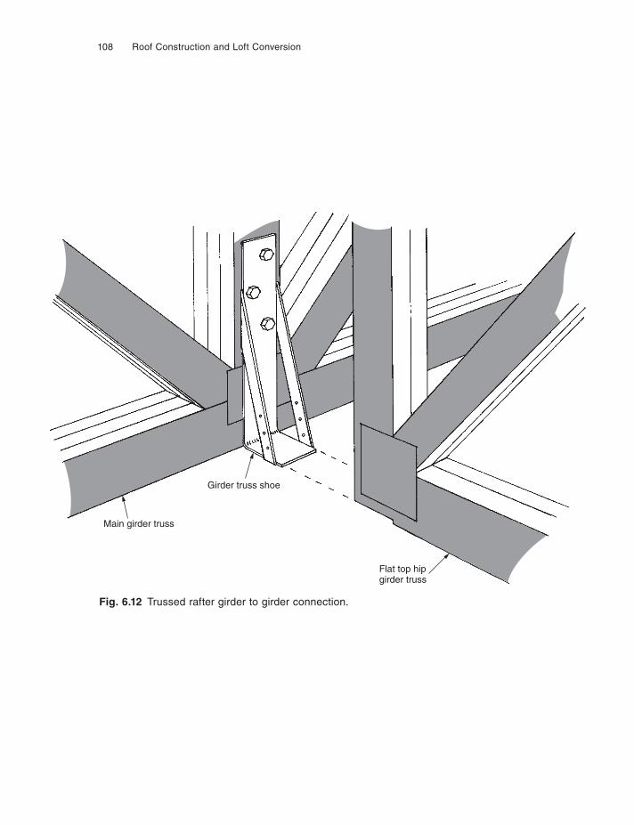
108 Roof Construction and Loft Conversion
Fig. 6.12 Trussed rafter girder to girder connection.
Main girder truss
Girder truss shoe
Flat top hipgirder truss
The Construction of Trussed Rafter Roofs 109
truss. A special galvanised steel shoe is required to transfer this load from the hip girder to the supporting girder. Fixing must be by bolts; screws and nails being in-adequate. Bolts should not be placed in the area of the connector plates, one solution being to bolt above the junction through one of the girder webs (see Fig. 6.12).
TRIMMINGS FOR OPENINGS
Small openings for fl ues or loft hatches are dealt with in Chapter 8 under the appropri-ate headings. Details below apply to large openings, i.e. those greater than two stan-dard trussed rafter spacings. Such openings can be provided using specially designed girder or compound trusses either side of the opening, or by taking support from the structure itself, in which case special trusses will be required for the infi ll area.
On the true trimmed opening, a purlin or purlins must be fi tted between the gird-ers onto which common rafters are fi xed. The ceiling joists will be supported on a purlin at bottom chord level on the girder truss. All purlins and binders must be fixed to the trussed rafters at the node or joint points. It is good practice to have the com-mon infi ll rafters 25 mm deeper than the top chord of the truss to allow for birdsmouth-ing over wall plate and purlin (see Fig. 6.13).
The alternative method, using the structure passing through the roof for support, is suitable for particularly large openings but does presuppose that the structure is built in advance. The special shaped trusses are shown in Fig. 6.14 and can be sup-ported either on steel shoes built into the structure or on a corbel. Care must be taken to stabilise the upper part of the special truss; this should be done with both binders and diagonal bracing.
Note that timber located adjacent to fl ues must conform to the rules laid down in the Building Regulations concerning the proximity of combustible materials. See the section in Chapter 8 of this book, ‘Trimming small openings’.
ATTIC AND LOFT ROOFS
For the purpose of this section an attic will be defined as a roof void used for living, bedroom, bathroom and kitchen, playroom or studio use, whilst loft will be a roof void intended for storage only.
One of the disadvantages of the normal fink or fan trussed rafter roof is that the many web members obstruct easy access within the roof void, a space traditionally used for storage of household items. The traditional purlin and common rafter roof described in Chapter 3 gives a relatively unobstructed loft space, although the collars may be well below a desirable headroom height. The TRADA roof described in Chapter 5 also gives a very usable loft void.
The trussed rafter roof can provide either a loft or an attic, if specifically designed to do so. If the roof is designed with a loft space which the designer knows, or be-cause of the shape of the internal members of the truss, can provide a room, then he should allow for domestic loading.
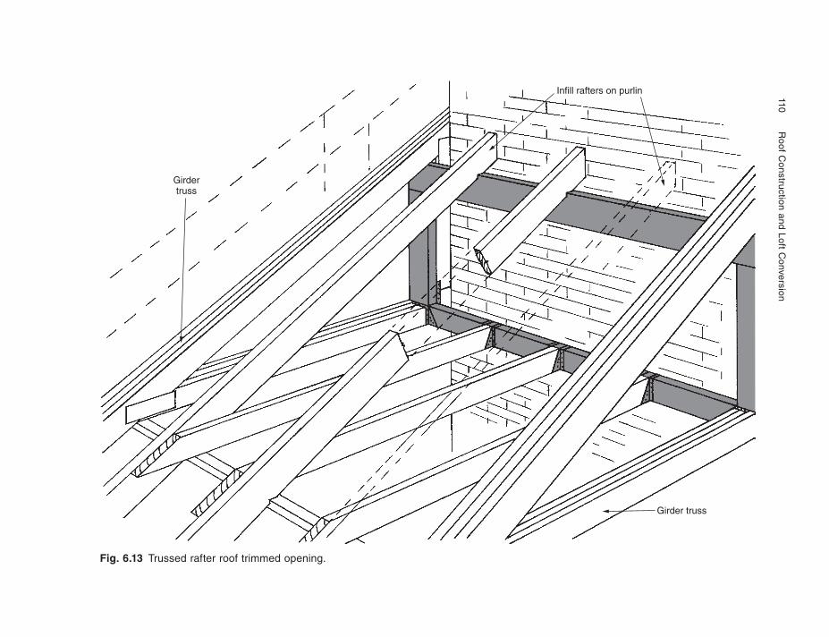
110
Roof C
onstruction and Loft Conversion
Fig. 6.13 Trussed rafter roof trimmed opening.
Infill rafters on purlin
Girdertruss
Girder truss
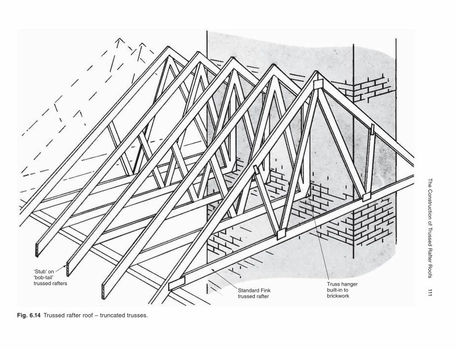
The C
onstruction of Trussed Rafter
Roofs
111
Fig. 6.14 Trussed rafter roof – truncated trusses.
‘Stub’ on‘bob-tail’trussed rafters
Standard Finktrussed rafter
Truss hangerbuilt-in tobrickwork
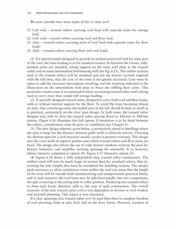
112 Roof Construction and Loft Conversion
We now consider four main types of loft or attic roof:
(1) Loft void – trussed rafters carrying roof load with separate joists for storage load.
(2) Loft void – trussed rafters carrying roof and fl oor load.(3) Attic – trussed rafters carrying most of roof load with separate joists for floor
loads.(4) Attic – trussed rafters carrying fl oor and roof loads.
(1) For special trusses designed to provide an unobstructed roof void for some part of the roof, the truss loading is as for standard trusses. In between the trusses, inde-pendent joists are installed, taking support on the same wall plate as the trussed rafter and on some intermediate load bearing wall (see Fig. 6.15). The timber sections used in the trussed rafters will be standard and not the heavier sections required with the full attic, thus the cost of the truss is not greatly increased. Care must be taken to add the necessary herringbone strutting, and the strutting indicated in the illustration on the intermediate wall plate to brace the infi lling fl oor joists. This particular construction is recommended where an existing trussed rafter roof is being used to carry more than simple loft storage loading.
(2) A specially designed trussed rafter, designed to carry both roof and fl oor loads, with or without internal support for the fl oor. To avoid the truss becoming almost an attic, thus containing costs, the loaded area of the loft should be kept as small as is practical, particularly on the clear span design. In both cases, the trussed rafter designer may seek to close the trussed rafter spacing down to 450 mm or 400 mm centres. Figure 6.16 illustrates this loft option. If insulation is to be fitted between the rafters, consideration must be given to ventilation (see Chapter 8).
(3) The attic design solution, given below, is particularly suited to dwellings where the span is large but the distance between gable walls is relatively narrow. Choosing the shortest span for a roof structure usually results in greatest economy. This design uses the cross-walls to support purlins onto which trussed rafters and fl oor joists are fixed. The design also allows the use of wide dormer windows without the need for heavier trimmers, and simplifies forming openings for stairwells. It is, however, labour intensive compared to option (4). Figure 6.17 illustrates option (3).
(4) Figure 6.18 shows a fully independent attic trussed rafter construction. The timbers used will now be much larger in section than for standard rafters, thus in-creasing the unit weight; this must be considered for handling reasons. The steeper pitch necessary to allow satisfactory room within the roof can mean that the height of the truss will be outside both manufacturing and transportation practical limits, and in such instances the roof truss may be split horizontally into two components, the split occurring at the ceiling joist or collar position. Producing two trussed rafters to form each frame therefore adds to the cost of such construction. The overall economy of the attic trussed rafter roof is very dependent on dormer or roof window and stairwell planning. This aspect is now discussed.
If a clear spanning attic trussed rafter is to be used then there is complete freedom of roof planning, both at attic level and on the floor below. However, location of
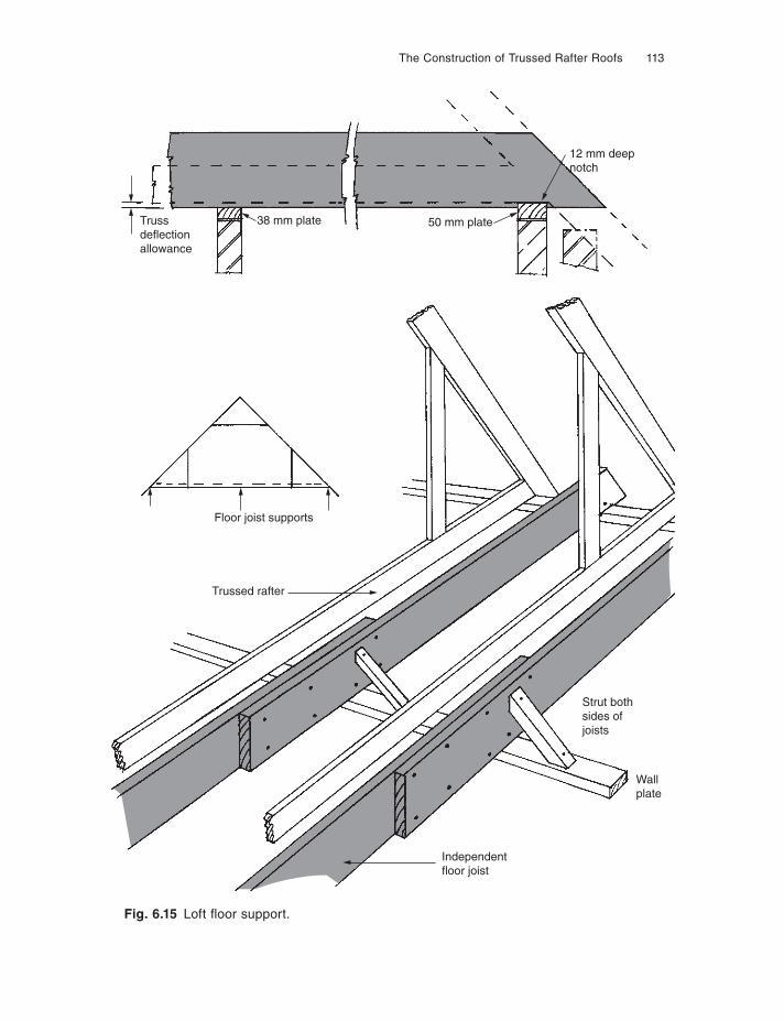
The Construction of Trussed Rafter Roofs 113
Fig. 6.15 Loft fl oor support.
Trussdeflectionallowance
38 mm plate 50 mm plate
12 mm deepnotch
Floor joist supports
Strut bothsides ofjoists
Wallplate
Independentfloor joist
Trussed rafter
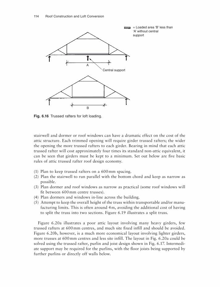
114 Roof Construction and Loft Conversion
Fig. 6.16 Trussed rafters for loft loading.
A
B
= Loaded area ‘B’ less than ‘A’ without centralsupport
Central support
stairwell and dormer or roof windows can have a dramatic effect on the cost of the attic structure. Each trimmed opening will require girder trussed rafters; the wider the opening the more trussed rafters to each girder. Bearing in mind that each attic trussed rafter will cost approximately four times its standard non-attic equivalent, it can be seen that girders must be kept to a minimum. Set out below are five basic rules of attic trussed rafter roof design economy.
(1) Plan to keep trussed rafters on a 600 mm spacing.(2) Plan the stairwell to run parallel with the bottom chord and keep as narrow as
possible.(3) Plan dormer and roof windows as narrow as practical (some roof windows will
fi t between 600 mm centre trusses).(4) Plan dormers and windows in-line across the building.(5) Attempt to keep the overall height of the truss within transportable and/or manu-
facturing limits. This is often around 4 m, avoiding the additional cost of having to split the truss into two sections. Figure 6.19 illustrates a split truss.
Figure 6.20a illustrates a poor attic layout involving many heavy girders, few trussed rafters at 600 mm centres, and much site fixed infi ll and should be avoided. Figure 6.20b, however, is a much more economical layout involving lighter girders, more trusses at 600 mm centres and less site infi ll. The layout in Fig. 6.20a could be solved using the trussed rafter, purlin and joist design shown in Fig. 6.17. Intermedi-ate support may be required for the purlins, with the fl oor joists being supported by further purlins or directly off walls below.
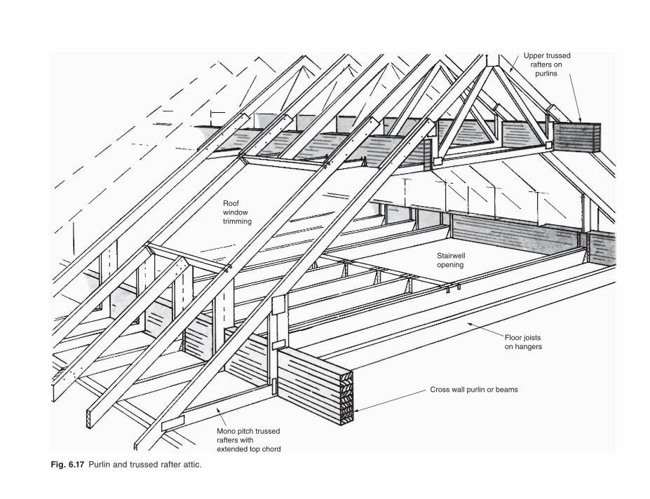
Fig. 6.17 Purlin and trussed rafter attic.
Cross wall purlin or beams
Mono pitch trussedrafters withextended top chord
Floor joistson hangers
Roofwindowtrimming
Stairwellopening
Upper trussedrafters on
purlins
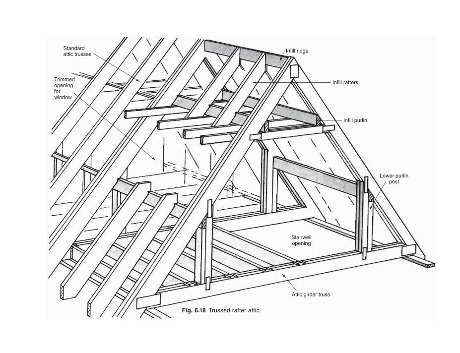
Infill ridge
Infill rafters
Infill purlin
Lower purlinpost
Attic girder truss
Stairwellopening
Standardattic trusses
Trimmedopeningforwindow
Fig. 6.18 Trussed rafter attic.
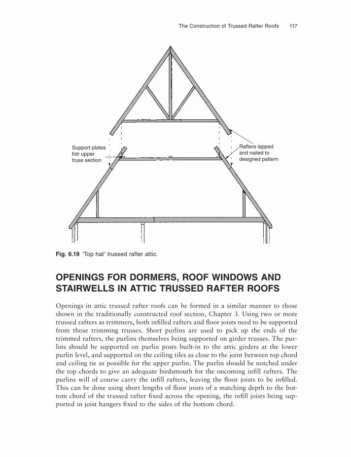
The Construction of Trussed Rafter Roofs 117
Fig. 6.19 ‘Top hat’ trussed rafter attic.
Support platesfotr uppertruss section
Rafters lappedand nailed todesigned pattern
OPENINGS FOR DORMERS, ROOF WINDOWS AND STAIRWELLS IN ATTIC TRUSSED RAFTER ROOFS
Openings in attic trussed rafter roofs can be formed in a similar manner to those shown in the traditionally constructed roof section, Chapter 3. Using two or more trussed rafters as trimmers, both infi lled rafters and fl oor joists need to be supported from those trimming trusses. Short purlins are used to pick up the ends of the trimmed rafters, the purlins themselves being supported on girder trusses. The pur-lins should be supported on purlin posts built-in to the attic girders at the lower purlin level, and supported on the ceiling tiles as close to the joint between top chord and ceiling tie as possible for the upper purlin. The purlin should be notched under the top chords to give an adequate birdsmouth for the oncoming infi ll rafters. The purlins will of course carry the infi ll rafters, leaving the fl oor joists to be infi lled. This can be done using short lengths of fl oor joists of a matching depth to the bot-tom chord of the trussed rafter fixed across the opening, the infi ll joists being sup-ported in joist hangers fixed to the sides of the bottom chord.
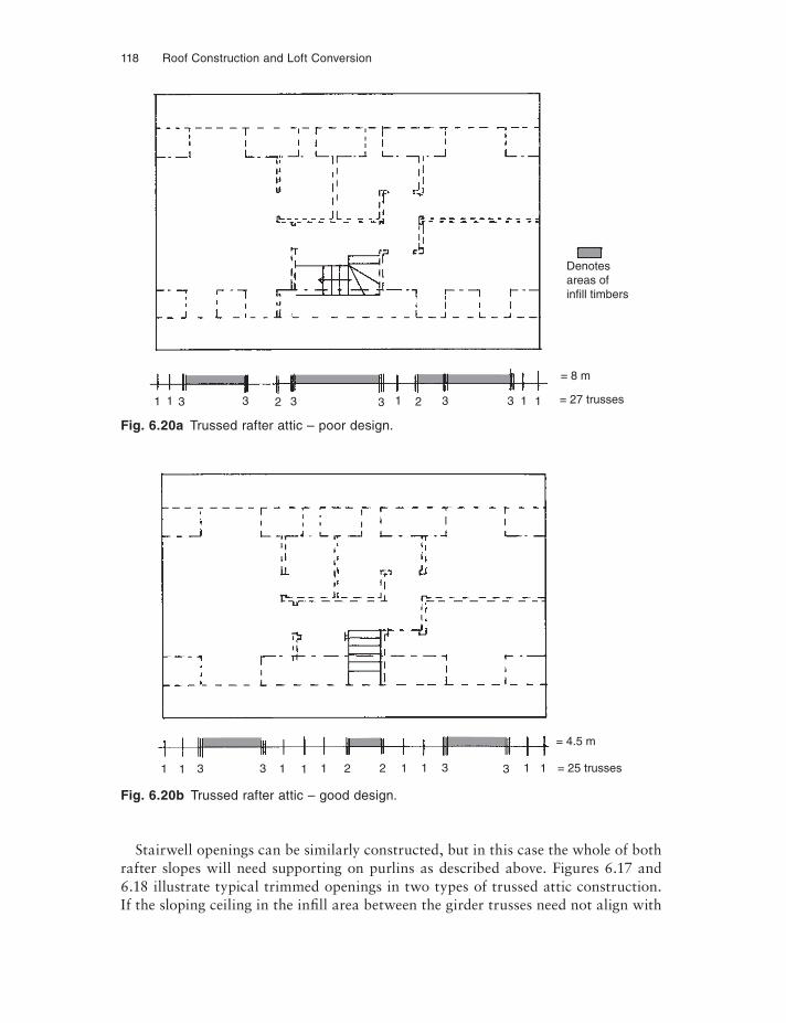
118 Roof Construction and Loft Conversion
Fig. 6.20a Trussed rafter attic – poor design.
Denotesareas ofinfill timbers
1 1 3 3 2 3 3 1 2 3 3 1 1
= 8 m
= 27 trusses
Fig. 6.20b Trussed rafter attic – good design.
1 1 3 3 1 1 1 2 2 1 1 3 3 1 1
= 4.5 m
= 25 trusses
Stairwell openings can be similarly constructed, but in this case the whole of both rafter slopes will need supporting on purlins as described above. Figures 6.17 and 6.18 illustrate typical trimmed openings in two types of trussed attic construction. If the sloping ceiling in the infi ll area between the girder trusses need not align with
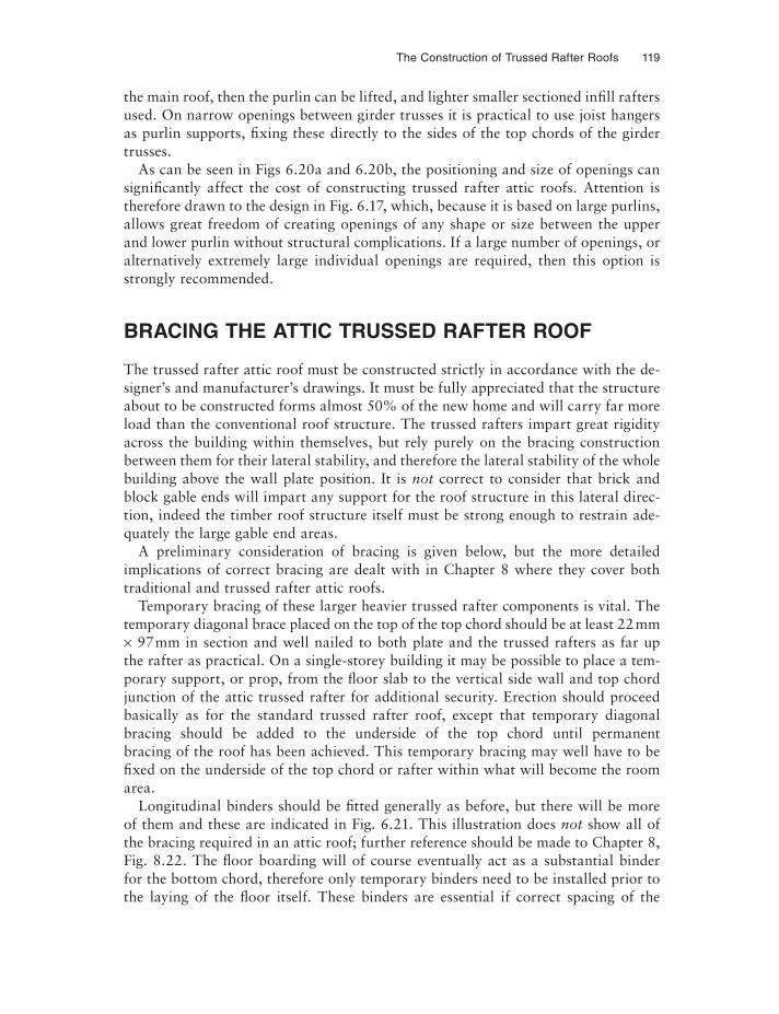
The Construction of Trussed Rafter Roofs 119
the main roof, then the purlin can be lifted, and lighter smaller sectioned infi ll rafters used. On narrow openings between girder trusses it is practical to use joist hangers as purlin supports, fixing these directly to the sides of the top chords of the girder trusses.
As can be seen in Figs 6.20a and 6.20b, the positioning and size of openings can significantly affect the cost of constructing trussed rafter attic roofs. Attention is therefore drawn to the design in Fig. 6.17, which, because it is based on large purlins, allows great freedom of creating openings of any shape or size between the upper and lower purlin without structural complications. If a large number of openings, or alternatively extremely large individual openings are required, then this option is strongly recommended.
BRACING THE ATTIC TRUSSED RAFTER ROOF
The trussed rafter attic roof must be constructed strictly in accordance with the de-signer’s and manufacturer’s drawings. It must be fully appreciated that the structure about to be constructed forms almost 50% of the new home and will carry far more load than the conventional roof structure. The trussed rafters impart great rigidity across the building within themselves, but rely purely on the bracing construction between them for their lateral stability, and therefore the lateral stability of the whole building above the wall plate position. It is not correct to consider that brick and block gable ends will impart any support for the roof structure in this lateral direc-tion, indeed the timber roof structure itself must be strong enough to restrain ade-quately the large gable end areas.
A preliminary consideration of bracing is given below, but the more detailed implications of correct bracing are dealt with in Chapter 8 where they cover both traditional and trussed rafter attic roofs.
Temporary bracing of these larger heavier trussed rafter components is vital. The temporary diagonal brace placed on the top of the top chord should be at least 22 mm × 97 mm in section and well nailed to both plate and the trussed rafters as far up the rafter as practical. On a single-storey building it may be possible to place a tem-porary support, or prop, from the fl oor slab to the vertical side wall and top chord junction of the attic trussed rafter for additional security. Erection should proceed basically as for the standard trussed rafter roof, except that temporary diagonal bracing should be added to the underside of the top chord until permanent bracing of the roof has been achieved. This temporary bracing may well have to be fixed on the underside of the top chord or rafter within what will become the room area.
Longitudinal binders should be fi tted generally as before, but there will be more of them and these are indicated in Fig. 6.21. This illustration does not show all of the bracing required in an attic roof; further reference should be made to Chapter 8, Fig. 8.22. The fl oor boarding will of course eventually act as a substantial binder for the bottom chord, therefore only temporary binders need to be installed prior to the laying of the fl oor itself. These binders are essential if correct spacing of the
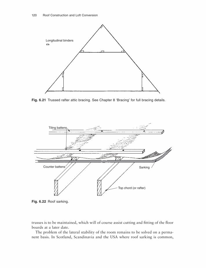
120 Roof Construction and Loft Conversion
Fig. 6.21 Trussed rafter attic bracing. See Chapter 8 ‘Bracing’ for full bracing details.
Longitudinal binders
Fig. 6.22 Roof sarking.
Tiling battens
Counter battens
Top chord (or rafter)
Sarking
trusses is to be maintained, which will of course assist cutting and fi tting of the floor boards at a later date.
The problem of the lateral stability of the room remains to be solved on a perma-nent basis. In Scotland, Scandinavia and the USA where roof sarking is common,
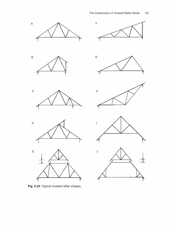
The Construction of Trussed Rafter Roofs 121
Fig. 6.23 Typical trussed rafter shapes.
A
B
C
D
E J
I
H
G
F
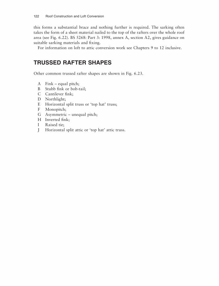
122 Roof Construction and Loft Conversion
this forms a substantial brace and nothing further is required. The sarking often takes the form of a sheet material nailed to the top of the rafters over the whole roof area (see Fig. 6.22). BS 5268: Part 3: 1998, annex A, section A2, gives guidance on suitable sarking materials and fixing.
For information on loft to attic conversion work see Chapters 9 to 12 inclusive.
TRUSSED RAFTER SHAPES
Other common trussed rafter shapes are shown in Fig. 6.23.
A Fink – equal pitch;B Stubb fink or bob-tail;C Cantilever fink;D Northlight;E Horizontal split truss or ‘top hat’ truss;F Monopitch;G Asymmetric – unequal pitch;H Inverted fink;I Raised tie;J Horizontal split attic or ‘top hat’ attic truss.
CHAPTER 7
Truss Plate Systems
Most users of trussed rafters will first come into contact with the name of one of the plate system manufacturers on receipt of a set of computer printed calculations. If these are not asked for, it is possible that the user may never know which brand of plate has been used in the manufacture of the trussed rafter supplied to him.
The plate manufacturers or ‘system owners’ supply both plates and design informa-tion to trussed rafter manufacturers who, clearly, are free to choose which system they prefer. The choice will be made on plate price, but more importantly (and in-creasingly a deciding factor) on the degree of design information and technical backup available from the system owner.
Whilst at first sight the type of plate used on the trussed rafter may seem of little importance to the end user, because his contract to purchase trussed rafters is with the trussed rafter manufacturer, it can affect both the quality of service and product supplied – and more importantly the precise construction form used on the roof.
The purchaser should be interested because the system owners, through their vari-ous manufacturers, can offer different forms of roof construction, some of which may appear very competitive on first sight but may involve a significantly higher site labour input than an alternative offer. The quality of the fabrication of the trussed rafter is another factor and this, to some extent, will be affected by the machinery and cutting data made available by the system owner to the fabricator. The purchaser is advised to ensure that his supplier is a member of the BM TRADA certification scheme and that the trusses are marked accordingly (see Fig. 6.3j and 6.3k).
SYSTEMS AVAILABLE
Changes involving the producers of the punched metal plates or system owners con-tinue. Gang-Nail, the original in the UK, is still producing. MiTek Industries Ltd, a combination of Bevplate and Hydro-Air, is still a major producer but has disposed of its builders’ fixings to Simpson Strong-tie. Wolf Systems Ltd was a newcomer when the second edition of this book was published, but since then has gone from strength to strength. In the author’s opinion this has been based on its superior ‘user friendly’
124 Roof Construction and Loft Conversion
computer engineering, not only for the trussed rafters themselves but for the whole roof design software.
The most recent change is the take-over of Truss Wall/Twinaplate by Alpine. Like most of the plate producers, Alpine is an international company and like all of the others has decades of experience to draw on. Although some names of plate produc-ers have changed, a core of experienced people remain within the industry; however, some have moved with the mergers and take-overs which have occurred. The author has known and worked with some of the senior engineers who are now running these companies for over 30 years.
All systems now have fully developed websites available for the provision of informa-tion off the internet, and all have information available on CD. Full details of all these systems companies and their website addresses can be found in the bibliography.
The amalgamation of some of the system owners is the result of the need to pool resources, particularly as the emphasis in system owners’ success has continued to shift towards the need to provide increasingly more sophisticated computer programs for their trussed rafter fabricators to use. The cost of producing these programs can only be recovered by the sale of the nail plates. The competition for plate customers – the trussed rafter manufacturers themselves – is therefore fi erce, continually driving the system owners to be ‘the best’ and thus attract more customers.
Most people know the name Gang-Nail, this being the generic term for punched metal plate connectors and indeed the company has the longest history of plate produc-tion in this country. Each plate producer has to conform to the standards set down in BS 5268: Part 3: 2000 and have a current certifi cate of conformity produced by a gov-ernment approved testing and assessment authority for each type of plate produced by them. pr EN 14545, Timber structures – connectors structures – requirements, is a rela-tively new standard which is likely to appear during the course of 2006, after which nail plate manufacturers will have up to 21 months to derive and declare the properties of their plates in accordance with its requirements. Historically this has meant an Agrément Board certifi cate, but now other private assessments bodies are authorised for this work and MiTek Industries has chosen Wimlas Ltd as their approving body. Other truss plate producers seem to have remained with the Agrément Board.
Gang-Nail produces both 14 and 20 gauge plates, with Wolf and MiTek producing 18 and 20 gauge plates. Alpine have a 20 and 16 gauge plate. All plates have to be marked with the manufacturer’s name. Immediately after take-over, as is now the case with Alpine, there may be some of the incorporated company’s plates still in circulation.
All companies have stainless steel plates available for trussed rafters for use in ag-gressive environments such as agriculture and some industrial situations. Standard plates are made from galvanised mild steel strip, this being simply punched with each producer’s individual nail-tooth pattern and shape and cut to size. They are generally coated with a protective oil (which also aids production), boxed and delivered to the trussed rafter manufacturer.
Most trussed rafter plate producers mark their plates by stamping the system name – some with colour for ease of identification. A wide range of plate sizes is produced by all manufacturers to cope with varying timber sizes and load stress.
Truss Plate Systems 125
The nail shape and pattern vary from one producer to another and affect the strength the plate can generate in the joint. Development of the nail profile, pattern and steel specification can therefore affect the size and cost of the plate needed to perform the given structural specification. This in turn will affect the cost of the plates on a truss and therefore the plate supplier’s customers’ competitiveness in seeking trussed rafter business. Gang-Nail, for instance, has its GN80X plate avail-able; this uses a special high-strength steel in 20 gauge and is particularly useful in reducing the cost of spliced joints. These are the end-to-end butt joints necessary in some top and bottom chords to give an adequate length of timber.
COMPUTER PROGRAMS
The trussed rafter industry is one of the most advanced producers of timber building components in the UK in terms of its computer aided design, drawing and production information. All systems now have a proprietary metal plated beam construction as has been seen earlier, and a number have wall panel design capability for timber framed house construction. This gives them the capability of designing the whole house and not just the roof structure. All plate producers supply their manufacturers with sophisticated software for use on networked personal computers, the PCs them-selves having become increasingly powerful particularly in their ability to handle graphics and process the data at high speed. The extensive use of email and data stored on easily transferable discs is now the ‘norm’, making information easily passed from system designer to roof designer and/or manufacturer and to end user. Programs now provide:
(1) The structural calculation of endless configurations of trussed rafters to easily establish the most economic solution with simple editing by the user to examine the ‘what if . . . ?” alternatives.
(2) Production of quotation from the selected design.(3) Production of that quotation in hard copy form by word processing combined
within the software for direct issue to the customer.(4) Generation of full engineering calculations for customers to issue to their clients
for Building Regulation approval.(5) Computer-aided drafting produced from simplifi ed input, to show roof layouts
and roof types and connection details. Many of these standard constructional points are drawn from a library in the computer data bank. Figure 7.1 illustrates a typical part layout from Wolf’s drafting software. This can be produced in black and white or colour, the latter of course helping to make the drawing easier to understand.
In addition, all now have general design packages to assist the roof designer with calculation and a selection of appropriate additional support members such as purlins and heavy beams. Alpine has a program they call Tool-box which in-cludes the above and allows for ply-gusseted joints in the design as well as other engineering aids.
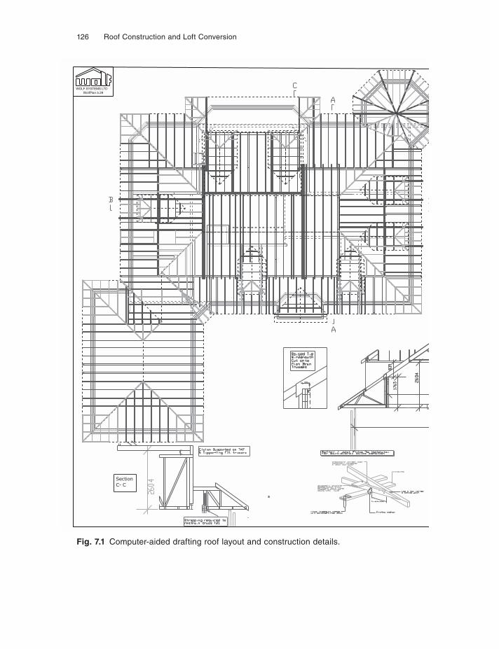
126 Roof Construction and Loft Conversion
SectionC- C
WOLF SYSTEMS LTD WolfPlan 5.29
Fig. 7.1 Computer-aided drafting roof layout and construction details.
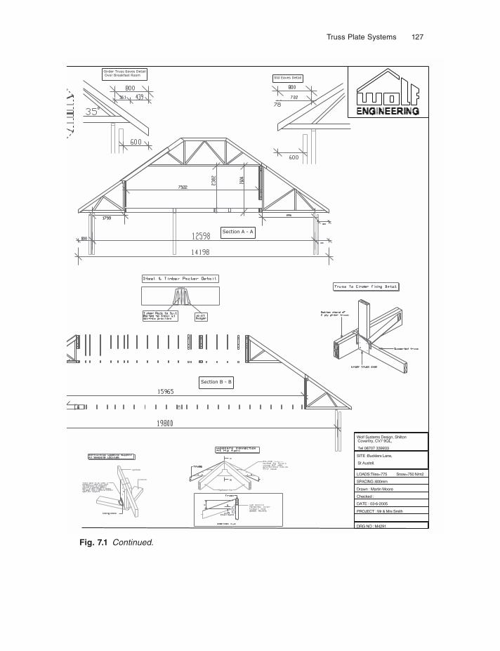
Truss Plate Systems 127
Section A - A
Section B - B
Std Eaves Detail
Girder Truss Eaves Detail Over Breakfast Room
DRG NO : M4291
PROJECT : Mr & Mrs Smith
DATE : 03-6-2005
SPACING :600mm
LOADS:Tiles=775 Snow=750 N/m2
SITE :Bucklers Lane,
St Austell.
Wolf Systems Design, Shilton Coventry, CV7 9QL,
Tel 08707 339933
Checked :
Drawn : Martin Moore
Fig. 7.1 Continued.
128 Roof Construction and Loft Conversion
(6) Manufacturing data including:(a) order picking, number of length and size and grade of timber, number and
size and specification of plates;(b) precise cutting data for each member of the trussed rafter including length
to the nearest millimetre and all angles and grade of timber (see Fig. 7.2);(c) plating data on each joint indicating plate size and its precise location on the
joint;(d) jig setting;(e) factory management data relating to production scheduling; some can go on
to stock control, giving automatic re-ordering levels for timber and plates.
Email is now used by many plate producers and the larger manufacturers for in-stant data transmission. The computer generated cutting data for instance can be fed directly from some centralised design office to the CNC component saws in the fac-tories of satellite manufacturers. This creates an almost paperless production process and of course eradicates the errors of transferring written data into the numeric controlled saws.
MiTek and Wolf have developed methods of precise plate location at each joint by projecting a laser generated image of the plate onto the timber in the manufacturing jig. These techniques are of course particularly helpful in improving the accuracy of plate placement not only on the first plate laid on the table before the timbers are laid on to it (because this particular plate could always be located by marks on the jig itself), but particularly for the top plate which is traditionally placed by the trained eye of the assembler. These techniques are still relatively new as this book goes to press, but if taken on board by the industry should significantly reduce the setting-up procedures prior to manufacturing each batch of trussed rafters, and will improve the accuracy of assembly and therefore the ultimate quality of the product.
All programs, now to varying extents, provide a ‘take-off’ facility for infi ll areas such as those around the hip and valley situations. These elements of the program are, of course, invaluable to those truss rafter manufacturers who provide ‘whole roof packages’, i.e. a package containing not only the roof trusses required, but also all infi ll timbers for hips, valleys, dormers, fascias, bargeboard and connecting metalwork.
TRAINING
All of this software sophistication is of course of little use unless the staff of each trussed rafter manufacturer are able to fully exploit it. It is here that the main dif-ferences now exist between trussed rafter manufacturers. All have the software available to them but few use all aspects of their plate supplier’s software packages. Computer-aided drafting, for instance, is still not commonplace with manufacturers with the exception of those using the Wolf system, whose program seems to be par-ticularly graphically oriented, but all use the quoting facility (although not perhaps the word processing element) (see point (3) on page 125), and all use the engineering
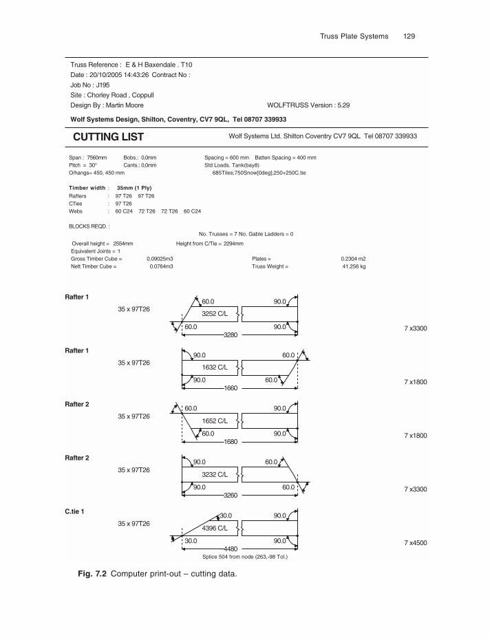
Truss Plate Systems 129
Truss Reference : E & H Baxendale . T10
Date : 20/10/2005 14:43:26 Contract No :
Job No : J195
Site : Chorley Road , Coppull
Design By : Martin Moore WOLFTRUSS Version : 5.29
Wolf Systems Design, Shilton, Coventry, CV7 9QL, Tel 08707 339933
CUTTING LIST Wolf Systems Ltd. Shilton Coventry CV7 9QL Tel 08707 339933
Span : Bobs.: Spacing = 600 mm Batten Spacing = 400 mm0,0mm7560mmPitch = Cants.: Std Loads. Tank(bay8)30° 0,0mm
685Tiles;750Snow[0deg];250+250C.tieO/hangs= 450, 450 mm
35mm (1 Ply)Timber width :
Rafters :Rafters : 97 T26 97 T26CTies : 97 T26
:Webs : 60 C24 72 T26 72 T26 60 C24
BLOCKS REQD. :No. Trusses = 7 No. Gable Ladders = 0
Overall height = 2554mm Height from C/Tie = 2294mmEquivalent Joints = 1Gross Timber Cube = 0.09025m3 Plates = 0.2304 m2Nett Timber Cube = 0.0764m3 Truss Weight = 41.256 kg
60.0
60.0
328090.0
90.0Rafter 1
35 x 97T263252 C/L
7 x3300
90.0
90.0
166060.0
60.0Rafter 1
35 x 97T261632 C/L
7 x1800
60.0
60.0
168090.0
90.0Rafter 2
35 x 97T261652 C/L
7 x1800
90.0
90.0
326060.0
60.0Rafter 2
35 x 97T263232 C/L
7 x3300
30.0
30.0
448090.0
90.0C.tie 1
35 x 97T264396 C/L
7 x4500
Splice 504 from node (263,-98 Tol.)
Fig. 7.2 Computer print-out – cutting data.
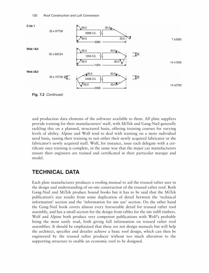
130 Roof Construction and Loft Conversion
90.0
90.0
308030.0
30.0C.tie 1
35 x 97T262996 C/L
7 x3300
90.0
90.0
120460.0
30.0
30
Web 1&4
35 x 60C241204 C/L
14 x1500
60.0
30.0
36
240830.0
30.0
36
Web 2&3
35 x 72T262408 C/L
14 x2700
Fig. 7.2 Continued.
and production data elements of the software available to them. All plate suppliers provide training for their manufacturers’ staff, with MiTek and Gang-Nail generally tackling this on a planned, structured basis, offering training courses for varying levels of ability. Alpine and Wolf tend to deal with training on a more individual need basis, tuning their training to suit either their newly acquired fabricator or the fabricator’s newly acquired staff. Wolf, for instance, issue each delegate with a cer-tificate once training is complete, in the same way that the major car manufacturers ensure their engineers are trained and certificated in their particular marque and model.
TECHNICAL DATA
Each plate manufacturer produces a roofi ng manual to aid the trussed rafter user in the design and understanding of on-site construction of the trussed rafter roof. Both Gang-Nail and MiTek produce bound books but it has to be said that the MiTek publication’s size results from some duplication of detail between the ‘technical information’ section and the ‘information for site use’ section. On the other hand the Gang-Nail book covers almost every foreseeable detail for trussed rafter roof assembly, and has a small section for the design from tables for the site infi ll timbers. Wolf and Alpine both produce very competent publications with Wolf’s probably being the most easily read, both giving full information on trussed rafter roof assemblies. It should be emphasised that these are not design manuals but will help the architect, specifi er and detailer achieve a basic roof design, which can then be engineered by the trussed rafter producer without too much alteration to the supporting structure to enable an economic roof to be designed.
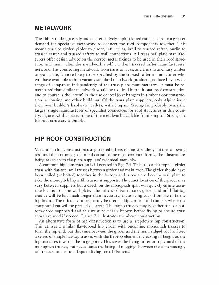
Truss Plate Systems 131
METALWORK
The ability to design easily and cost-effectively sophisticated roofs has led to a greater demand for specialist metalwork to connect the roof components together. This means truss to girder, girder to girder, infi ll truss, infi ll to trussed rafter, purlin to trussed rafter and trussed rafters to wall connections. All truss nail plate manufac-turers offer design advice on the correct metal fixings to be used in their roof struc-ture, and many offer the metalwork itself via their trussed rafter manufacturers’ network. The connecting metalwork from truss to truss, and truss to ancillary timber or wall plate, is more likely to be specifi ed by the trussed rafter manufacturer who will have available to him various standard metalwork products produced by a wide range of companies independently of the truss plate manufacturers. It must be re-membered that similar metalwork would be required in traditional roof construction and of course is the ‘norm’ in the use of steel joist hangers in timber fl oor construc-tion in housing and other buildings. Of the truss plate suppliers, only Alpine issue their own builder’s hardware leaflets, with Simpson Strong-Tie probably being the largest single manufacturer of specialist connectors for roof structures in this coun-try. Figure 7.3 illustrates some of the metalwork available from Simpson Strong-Tie for roof structure assembly.
HIP ROOF CONSTRUCTION
Variation in hip construction using trussed rafters is almost endless, but the following text and illustrations give an indication of the most common forms, the illustrations being taken from the plate suppliers’ technical manuals.
A common hip construction is illustrated in Fig. 7.4. This uses a flat-topped girder truss with flat-top infi ll trusses between girder and main roof. The girder should have been nailed (or bolted) together in the factory and is positioned on the wall plate to take the monopitch hip infi ll trusses it supports. The exact location of the girder may vary between suppliers but a check on the monopitch span will quickly ensure accu-rate location on the wall plate. The rafters of both mono, girder and infi ll flat-top trusses will be left much longer than necessary, these being cut off on site to fi t the hip board. The offcuts can frequently be used as hip corner infi ll timbers where the compound cut will be precisely correct. The mono trusses may be either top- or bot-tom-chord supported and this must be clearly known before fixing to ensure truss shoes are used if needed. Figure 7.4 illustrates the above construction.
An alternative form of hip construction is to use a ‘stepdown’ hip construction. This utilises a similar flat-topped hip girder with oncoming monopitch trusses to form the hip end, but this time between the girder and the main ridged roof is fitted a series of simple flat-top trusses with the flat-top element increasing in height as the hip increases towards the ridge point. This saves the flying rafter or top chord of the monopitch trusses, but necessitates the fi tting of noggings between these increasingly tall trusses to ensure adequate fixing for tile battens.
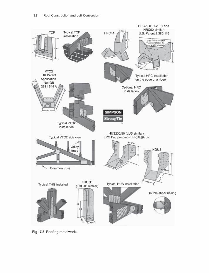
132 Roof Construction and Loft Conversion
Fig. 7.3 Roofi ng metalwork.
TCP Typical TCPinstallation
HRC44
Optional HRCinstallation
VTC2UK Patent
ApplicationNo: GB
2381 544 A
Typical VTC2installation
Typical VTC2 side view
THG3B(THG4B similar)
Double shear nailing
HGUS
Typical HUS installationTypical THG installed
Common truss
Valleytruss
HUS230/50 (LUS similar)EPC Pat. pending (FR)(DE)(GB)
Typical HRC installationon the edge of a ridge
HRC22 (HRC1.81 and HRC50 similar)
U.S. Patent 2,380,116W
Slots for bend locationwhen installed on theend of a 38 mm ridge
217
148
216
W45°
45°
87
117
90
65
106
H
W
100
67
H
W
HB
W
B
H
B
40
73
40
46
100
Truss Plate Systems 133
Other variations of hip construction exist and it is wise to seek the manufacturer’s hip construction detailed notes before proceeding on site.
Bonnet or gable hipFigure 7.5 illustrates a typical construction for this hip form. To carry the weight of the hipped element of the roof, the Fink of the main roof would probably not be strong enough on the bottom chord. The Howe configuration has an extra support on the bottom chord, dividing the span into four rather than three bays of the Fink. Again a girder will be formed of two (or three) Howe trusses, and this time the monopitch truss will defi nitely be bottom-chord supported in truss shoes. The upper part of the Howe (that triangle above the monopitch roof), will have to carry some form of cladding, possibly rendering or boarding. The additional weight of this clad-ding must not be overlooked when designing the truss.
Fig. 7.4 Hip roof trussed rafter layout.
The horizontal top chords to theflat top trusses are to be well braced together to resist lateral buckling
Infill Jack Raftersto be a minimum of 25mmdeeper than trussed raftermembers to allow forbirdmouthing at wallplate
Infill Ceiling Joists
Mono Pitch Trussessuppplied with extendedrafters for site cuttingto suit hip boards Noggings to be nailed
to ceiling joist and sideof jack rafter
Flat Top Trussessupplied with extendedrafters for site cutting tosuit hip boards
StandardTrusses toMain Roof
Compound Girderof Flat Top Trussespermanently fixedtogether
Hip Boards to be birdmouthedover the compound girder of flat toptrusses and over the wallplate
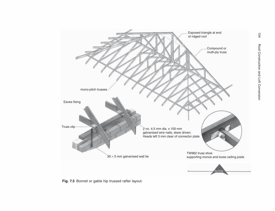
134
R
oof Construction and Loft C
onversion
Fig. 7.5 Bonnet or gable hip trussed rafter layout.
Exposed triangle at endof ridged roof
Compound ormulti-ply truss
2 no. 4.5 mm dia. x 100 mmgalvanised wire nails, skew driven.Heads left 3 mm clear of connector plate
mono-pitch trusses
Eaves fixing
Truss clip
30 × 5 mm galvanised wall tieTW962 truss shoe supporting monos and loose ceiling joists
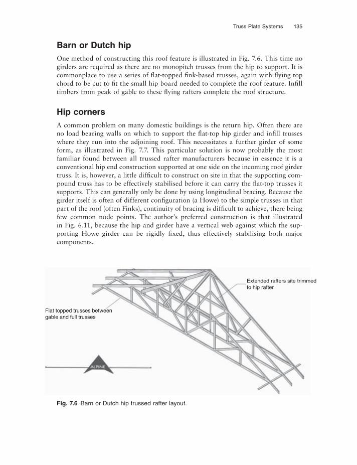
Truss Plate Systems 135
Barn or Dutch hipOne method of constructing this roof feature is illustrated in Fig. 7.6. This time no girders are required as there are no monopitch trusses from the hip to support. It is commonplace to use a series of flat-topped fink-based trusses, again with flying top chord to be cut to fi t the small hip board needed to complete the roof feature. Infi ll timbers from peak of gable to these fl ying rafters complete the roof structure.
Hip cornersA common problem on many domestic buildings is the return hip. Often there are no load bearing walls on which to support the flat-top hip girder and infi ll trusses where they run into the adjoining roof. This necessitates a further girder of some form, as illustrated in Fig. 7.7. This particular solution is now probably the most familiar found between all trussed rafter manufacturers because in essence it is a conventional hip end construction supported at one side on the incoming roof girder truss. It is, however, a little difficult to construct on site in that the supporting com-pound truss has to be effectively stabilised before it can carry the flat-top trusses it supports. This can generally only be done by using longitudinal bracing. Because the girder itself is often of different configuration (a Howe) to the simple trusses in that part of the roof (often Finks), continuity of bracing is difficult to achieve, there being few common node points. The author’s preferred construction is that illustrated in Fig. 6.11, because the hip and girder have a vertical web against which the sup-porting Howe girder can be rigidly fixed, thus effectively stabilising both major components.
Fig. 7.6 Barn or Dutch hip trussed rafter layout.
Flat topped trusses betweengable and full trusses
Extended rafters site trimmedto hip rafter
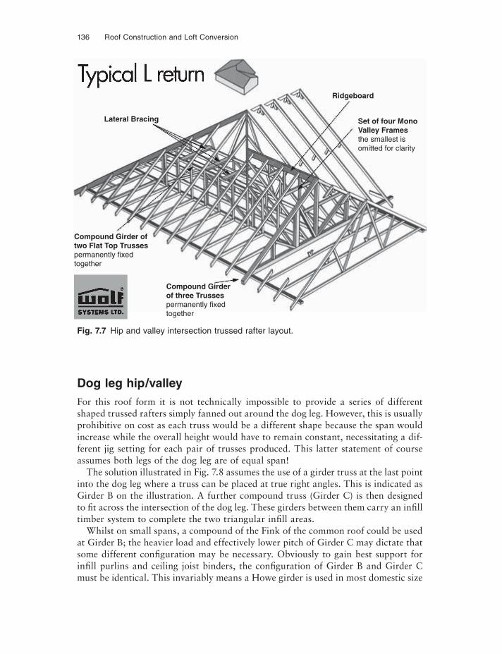
136 Roof Construction and Loft Conversion
Dog leg hip/valleyFor this roof form it is not technically impossible to provide a series of different shaped trussed rafters simply fanned out around the dog leg. However, this is usually prohibitive on cost as each truss would be a different shape because the span would increase while the overall height would have to remain constant, necessitating a dif-ferent jig setting for each pair of trusses produced. This latter statement of course assumes both legs of the dog leg are of equal span!
The solution illustrated in Fig. 7.8 assumes the use of a girder truss at the last point into the dog leg where a truss can be placed at true right angles. This is indicated as Girder B on the illustration. A further compound truss (Girder C) is then designed to fi t across the intersection of the dog leg. These girders between them carry an infi ll timber system to complete the two triangular infi ll areas.
Whilst on small spans, a compound of the Fink of the common roof could be used at Girder B; the heavier load and effectively lower pitch of Girder C may dictate that some different configuration may be necessary. Obviously to gain best support for infi ll purlins and ceiling joist binders, the configuration of Girder B and Girder C must be identical. This invariably means a Howe girder is used in most domestic size
Fig. 7.7 Hip and valley intersection trussed rafter layout.
Lateral Bracing
Compound Girder oftwo Flat Top Trussespermanently fixedtogether
Ridgeboard
Set of four MonoValley Framesthe smallest isomitted for clarity
Compound Girderof three Trussespermanently fixedtogether
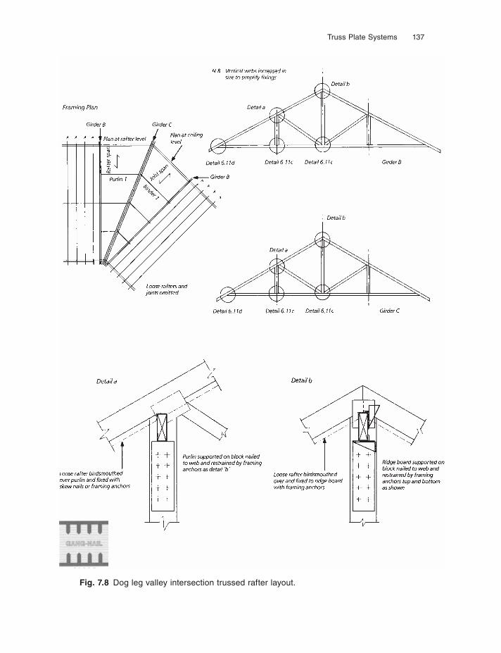
Truss Plate Systems 137
Fig. 7.8 Dog leg valley intersection trussed rafter layout.
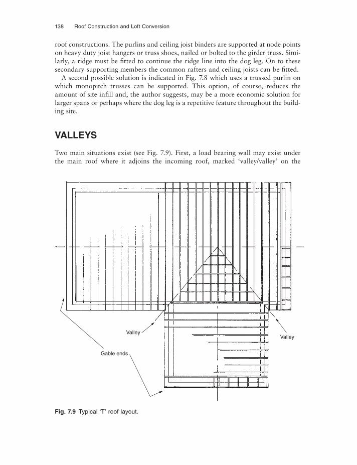
138 Roof Construction and Loft Conversion
roof constructions. The purlins and ceiling joist binders are supported at node points on heavy duty joist hangers or truss shoes, nailed or bolted to the girder truss. Simi-larly, a ridge must be fi tted to continue the ridge line into the dog leg. On to these secondary supporting members the common rafters and ceiling joists can be fitted.
A second possible solution is indicated in Fig. 7.8 which uses a trussed purlin on which monopitch trusses can be supported. This option, of course, reduces the amount of site infi ll and, the author suggests, may be a more economic solution for larger spans or perhaps where the dog leg is a repetitive feature throughout the build-ing site.
VALLEYS
Two main situations exist (see Fig. 7.9). First, a load bearing wall may exist under the main roof where it adjoins the incoming roof, marked ‘valley/valley’ on the
Fig. 7.9 Typical ‘T’ roof layout.
Gable ends
ValleyValley
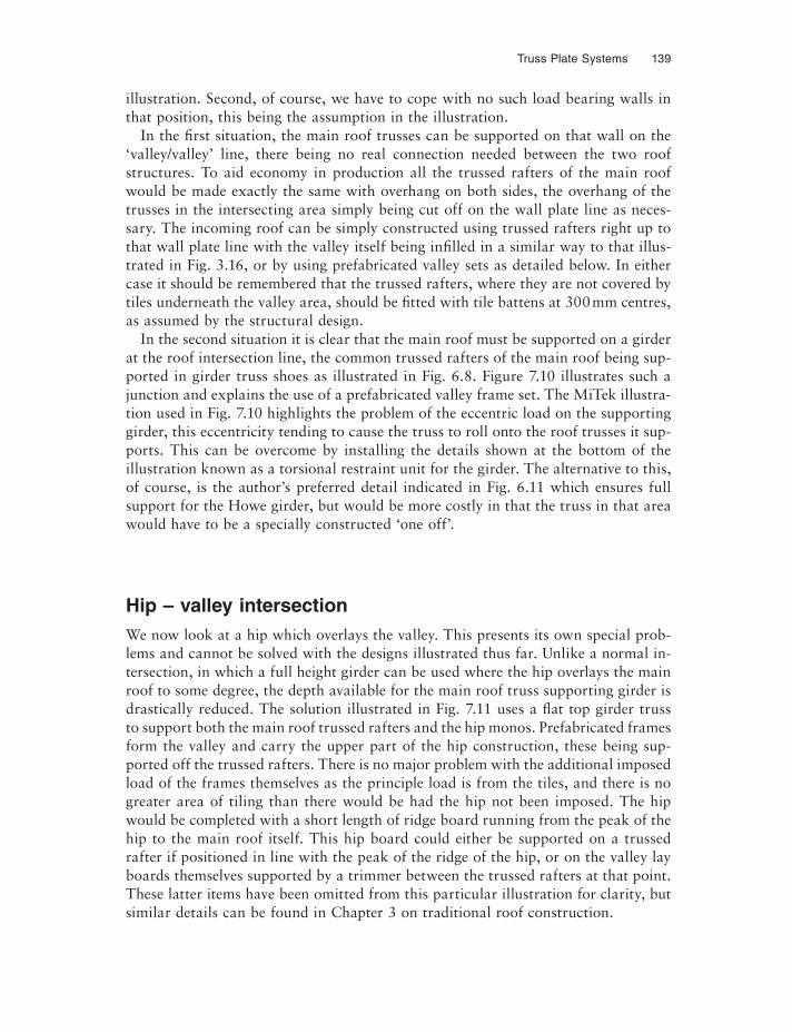
Truss Plate Systems 139
illustration. Second, of course, we have to cope with no such load bearing walls in that position, this being the assumption in the illustration.
In the first situation, the main roof trusses can be supported on that wall on the ‘valley/valley’ line, there being no real connection needed between the two roof structures. To aid economy in production all the trussed rafters of the main roof would be made exactly the same with overhang on both sides, the overhang of the trusses in the intersecting area simply being cut off on the wall plate line as neces-sary. The incoming roof can be simply constructed using trussed rafters right up to that wall plate line with the valley itself being infi lled in a similar way to that illus-trated in Fig. 3.16, or by using prefabricated valley sets as detailed below. In either case it should be remembered that the trussed rafters, where they are not covered by tiles underneath the valley area, should be fi tted with tile battens at 300 mm centres, as assumed by the structural design.
In the second situation it is clear that the main roof must be supported on a girder at the roof intersection line, the common trussed rafters of the main roof being sup-ported in girder truss shoes as illustrated in Fig. 6.8. Figure 7.10 illustrates such a junction and explains the use of a prefabricated valley frame set. The MiTek illustra-tion used in Fig. 7.10 highlights the problem of the eccentric load on the supporting girder, this eccentricity tending to cause the truss to roll onto the roof trusses it sup-ports. This can be overcome by installing the details shown at the bottom of the illustration known as a torsional restraint unit for the girder. The alternative to this, of course, is the author’s preferred detail indicated in Fig. 6.11 which ensures full support for the Howe girder, but would be more costly in that the truss in that area would have to be a specially constructed ‘one off’.
Hip – valley intersectionWe now look at a hip which overlays the valley. This presents its own special prob-lems and cannot be solved with the designs illustrated thus far. Unlike a normal in-tersection, in which a full height girder can be used where the hip overlays the main roof to some degree, the depth available for the main roof truss supporting girder is drastically reduced. The solution illustrated in Fig. 7.11 uses a flat top girder truss to support both the main roof trussed rafters and the hip monos. Prefabricated frames form the valley and carry the upper part of the hip construction, these being sup-ported off the trussed rafters. There is no major problem with the additional imposed load of the frames themselves as the principle load is from the tiles, and there is no greater area of tiling than there would be had the hip not been imposed. The hip would be completed with a short length of ridge board running from the peak of the hip to the main roof itself. This hip board could either be supported on a trussed rafter if positioned in line with the peak of the ridge of the hip, or on the valley lay boards themselves supported by a trimmer between the trussed rafters at that point. These latter items have been omitted from this particular illustration for clarity, but similar details can be found in Chapter 3 on traditional roof construction.
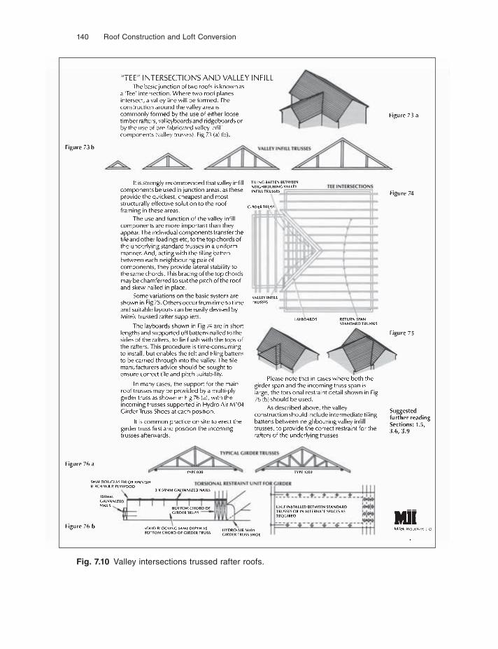
140 Roof Construction and Loft Conversion
Fig. 7.10 Valley intersections trussed rafter roofs.
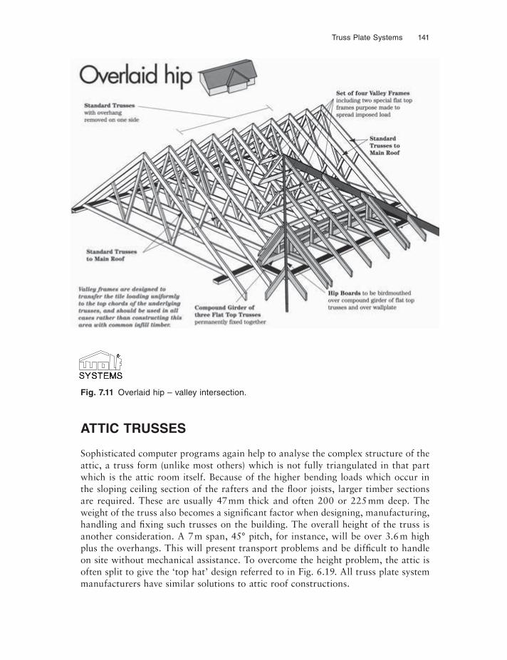
Truss Plate Systems 141
ATTIC TRUSSES
Sophisticated computer programs again help to analyse the complex structure of the attic, a truss form (unlike most others) which is not fully triangulated in that part which is the attic room itself. Because of the higher bending loads which occur in the sloping ceiling section of the rafters and the fl oor joists, larger timber sections are required. These are usually 47 mm thick and often 200 or 225 mm deep. The weight of the truss also becomes a significant factor when designing, manufacturing, handling and fixing such trusses on the building. The overall height of the truss is another consideration. A 7 m span, 45° pitch, for instance, will be over 3.6 m high plus the overhangs. This will present transport problems and be difficult to handle on site without mechanical assistance. To overcome the height problem, the attic is often split to give the ‘top hat’ design referred to in Fig. 6.19. All truss plate system manufacturers have similar solutions to attic roof constructions.
Fig. 7.11 Overlaid hip – valley intersection.
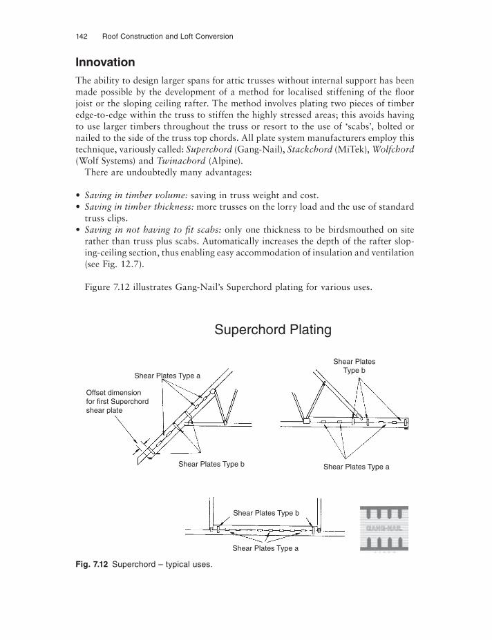
142 Roof Construction and Loft Conversion
InnovationThe ability to design larger spans for attic trusses without internal support has been made possible by the development of a method for localised stiffening of the floor joist or the sloping ceiling rafter. The method involves plating two pieces of timber edge-to-edge within the truss to stiffen the highly stressed areas; this avoids having to use larger timbers throughout the truss or resort to the use of ‘scabs’, bolted or nailed to the side of the truss top chords. All plate system manufacturers employ this technique, variously called: Superchord (Gang-Nail), Stackchord (MiTek), Wolfchord(Wolf Systems) and Twinachord (Alpine).
There are undoubtedly many advantages:
• Saving in timber volume: saving in truss weight and cost.• Saving in timber thickness: more trusses on the lorry load and the use of standard
truss clips.• Saving in not having to fit scabs: only one thickness to be birdsmouthed on site
rather than truss plus scabs. Automatically increases the depth of the rafter slop-ing-ceiling section, thus enabling easy accommodation of insulation and ventilation (see Fig. 12.7).
Figure 7.12 illustrates Gang-Nail’s Superchord plating for various uses.
Fig. 7.12 Superchord – typical uses.
Shear Plates Type a
Offset dimensionfor first Superchordshear plate
Shear Plates Type b
Shear Plates Type b
Shear Plates Type a
Shear Plates Type a
Shear PlatesType b
Superchord Plating
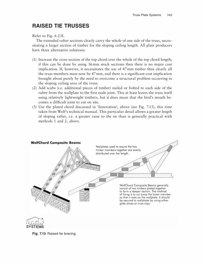
Truss Plate Systems 143
RAISED TIE TRUSSES
Refer to Fig. 6.23I.The extended rafter sections clearly carry the whole of one side of the truss, neces-
sitating a larger section of timber for the sloping ceiling length. All plate producers have three alternative solutions:
(1) Increase the cross section of the top chord over the whole of the top chord length; if this can be done by using 36 mm stock sections then there is no major cost implication. If, however, it necessitates the use of 47 mm timber then clearly all the truss members must now be 47 mm, and there is a significant cost implication brought about purely by the need to overcome a structural problem occurring in the sloping ceiling area of the truss.
(2) Add scabs (i.e. additional pieces of timber) nailed or bolted to each side of the rafter from the wallplate to the first node joint. This at least leaves the truss itself using relatively lightweight timbers, but it does mean that the bird’s mouth be-comes a difficult joint to cut on site.
(3) Use the plated chord discussed in ‘Innovation’, above (see Fig. 7.13), this time taken from Wolf’s technical manual. This particular detail allows a greater length of sloping rafter, i.e. a greater raise to the tie than is generally practical with methods 1 and 2, above.
Fig. 7.13 Raised tie bracing.
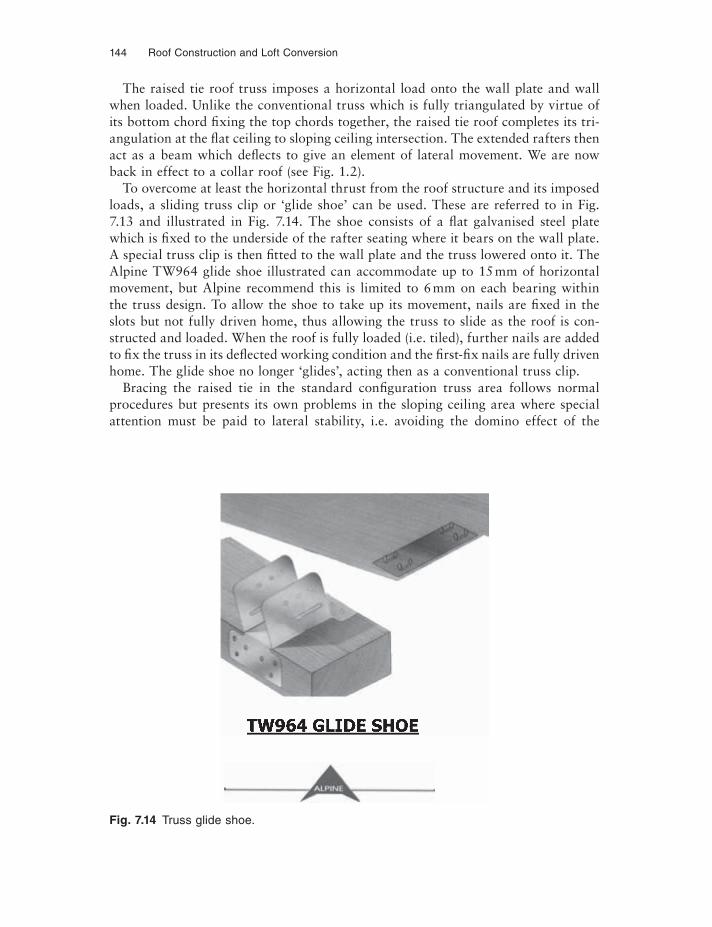
144 Roof Construction and Loft Conversion
The raised tie roof truss imposes a horizontal load onto the wall plate and wall when loaded. Unlike the conventional truss which is fully triangulated by virtue of its bottom chord fixing the top chords together, the raised tie roof completes its tri-angulation at the flat ceiling to sloping ceiling intersection. The extended rafters then act as a beam which deflects to give an element of lateral movement. We are now back in effect to a collar roof (see Fig. 1.2).
To overcome at least the horizontal thrust from the roof structure and its imposed loads, a sliding truss clip or ‘glide shoe’ can be used. These are referred to in Fig. 7.13 and illustrated in Fig. 7.14. The shoe consists of a flat galvanised steel plate which is fixed to the underside of the rafter seating where it bears on the wall plate. A special truss clip is then fi tted to the wall plate and the truss lowered onto it. The Alpine TW964 glide shoe illustrated can accommodate up to 15 mm of horizontal movement, but Alpine recommend this is limited to 6 mm on each bearing within the truss design. To allow the shoe to take up its movement, nails are fixed in the slots but not fully driven home, thus allowing the truss to slide as the roof is con-structed and loaded. When the roof is fully loaded (i.e. tiled), further nails are added to fix the truss in its defl ected working condition and the first-fix nails are fully driven home. The glide shoe no longer ‘glides’, acting then as a conventional truss clip.
Bracing the raised tie in the standard configuration truss area follows normal procedures but presents its own problems in the sloping ceiling area where special attention must be paid to lateral stability, i.e. avoiding the domino effect of the
Fig. 7.14 Truss glide shoe.
Truss Plate Systems 145
trussed rafters. Options 1 and 2, above, produce relatively stiff trusses in this area and the length of the sloping ceiling is relatively small compared to the plated chord solution. This latter technique needs special considerations, as follows:
(1) Because the thickness of the plated chord is relatively slim compared to its depth, buckling must be avoided and solid blocking should be fi tted between the trusses in the raised tie area. This would follow similar practice used for fl oor joists.
(2) Because the length of the sloping ceiling rafter is probably greater, there is prob-ably a greater need to diagonally brace this element of the roof.
This additional bracing can be provided in three ways:
(1) Sheath the roof on the top of the rafters, a common practice in Scotland and Scandinavian countries where it is known as a sarking (see Fig. 6.22).
(2) Continue the under rafter diagonal bracing down over the underside of the sloping ceiling rafter. The change of plane presents problems which have to be effectively dealt with by blocking down from the common diagonal brace to the plated chord diagonal brace. This also means further packing out for fi tting of plasterboard.
(3) Fit ply between rafters utilising the solid blocking mentioned above as support. Figure 7.15, again from Gang-Nail’s Technical Bulletin 126, shows the use of plywood in this situation.
Option 3 is preferred by the author because the ply can perform two functions: fi rst it stabilises the roof and uses the solid blocking as support; second it provides the ventilation void in the sloping section. This is basically the same technique as that used for stabilising attic trusses (see Fig. 8.22).
PUNCHED NAIL PLATE JOISTS, RAFTERS AND PURLINS
Initially developed in the USA and Canada for long span fl oor and flat roof joists, the product consists of an upper and lower timber chord spaced apart by special metal ‘V’ pressings which at the top and bottom of the ‘V’ have punched nails similar to the trussed rafter connector plate. When pressed into the top and bottom flanges or chords, these ‘V’s produce a lattice girder.
The advantages:
(1) The economic use of timber.(2) A precision engineered component.(3) Easy installation of services such as electric cables, plumbing pipes, and small
ducts through the lattice.(4) Wide fixing chords for fl oor and ceiling decking.
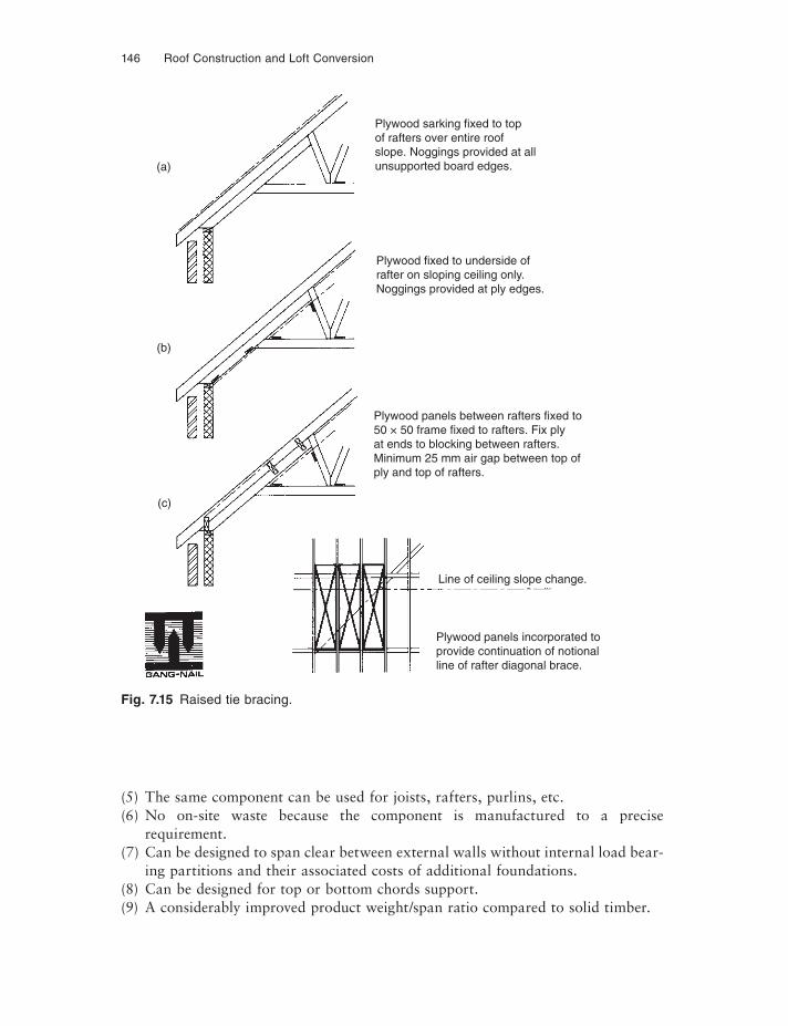
146 Roof Construction and Loft Conversion
Fig. 7.15 Raised tie bracing.
(5) The same component can be used for joists, rafters, purlins, etc.(6) No on-site waste because the component is manufactured to a precise
requirement.(7) Can be designed to span clear between external walls without internal load bear-
ing partitions and their associated costs of additional foundations.(8) Can be designed for top or bottom chords support.(9) A considerably improved product weight/span ratio compared to solid timber.
Plywood sarking fixed to topof rafters over entire roofslope. Noggings provided at allunsupported board edges.
Plywood fixed to underside ofrafter on sloping ceiling only.Noggings provided at ply edges.
Line of ceiling slope change.
(b)
(c)
(a)
Plywood panels incorporated toprovide continuation of notionalline of rafter diagonal brace.
Plywood panels between rafters fixed to50 × 50 frame fixed to rafters. Fix plyat ends to blocking between rafters.Minimum 25 mm air gap between top ofply and top of rafters.
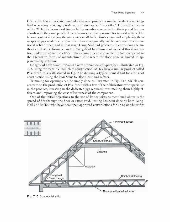
Truss Plate Systems 147
One of the first truss system manufacturers to produce a similar product was Gang-Nail who many years ago produced a product called ‘Econofl or’. This earlier version of the ‘V’ lattice beam used timber lattice members connected to the top and bottom chords with the same punched metal connector plates as used for trussed rafters. The labour content in cutting the numerous small lattice timbers and indeed placing them in special jigs made the product less than economically viable compared to conven-tional solid timber, and at that stage Gang-Nail had problems in convincing the au-thorities of its performance in fire. Gang-Nail have now reintroduced this construc-tion under the name ‘Eco-fl oor’. They claim it is now a viable product compared to the alternative forms of manufactured joist where the floor zone is limited to ap-proximately 200 mm.
Gang-Nail have since produced a new product called SpaceJoist, illustrated in Fig. 7.16, using the metal ‘V’ nail plate construction. MiTek have a similar product called Posi-Strut; this is illustrated in Fig. 7.17 showing a typical joint detail for attic roof construction using the Posi-Strut for fl oor joist and rafters.
Trimming for openings can be simply done as illustrated in Fig. 7.17. MiTek con-centrate on the production of Posi-Strut with a few of their fabricators who specialise in the product, investing in the dedicated jigs required, thus making them highly ef-fi cient and improving the cost effectiveness of the component.
One of the initial objections to the use of lattice joists as mentioned above is the spread of fire through the fl oor or rafter void. Testing has been done by both Gang-Nail and MiTek who have developed approved constructions for up to one hour fire
Fig. 7.16 SpaceJoist attic.
Plywood gusset
SpaceJoist truss
Collar tie
lnsulation
Gang-Nailstrap hanger
Chipboard flooring
Clearspan SpaceJoist truss
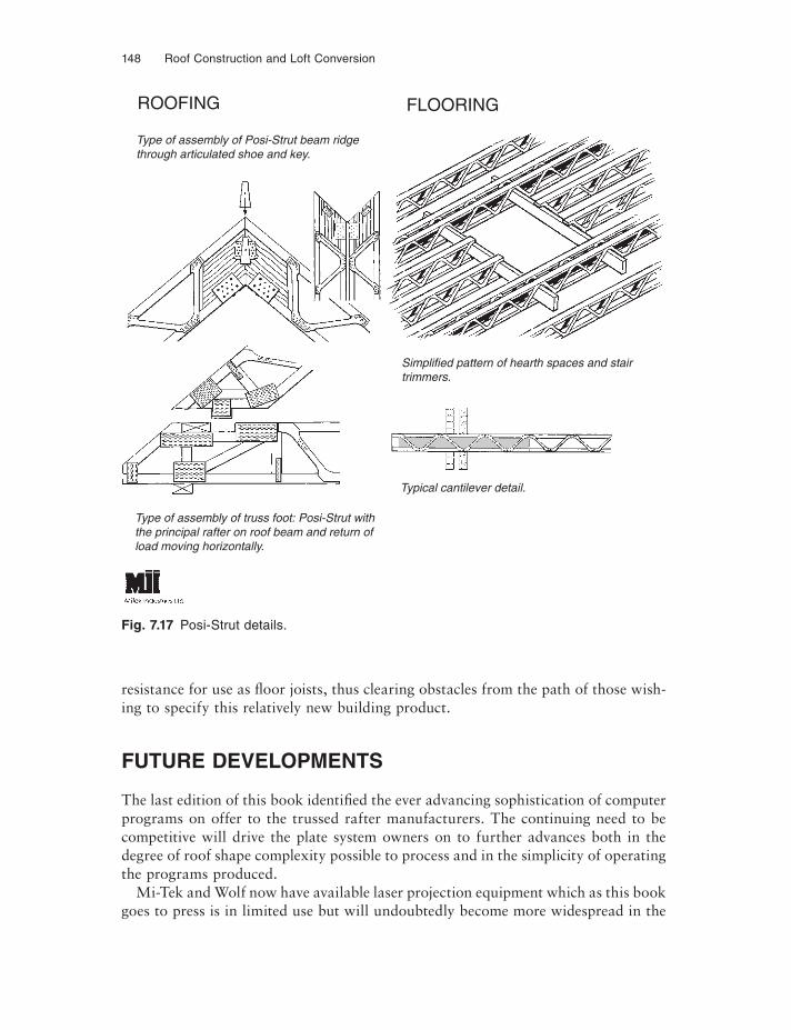
148 Roof Construction and Loft Conversion
resistance for use as fl oor joists, thus clearing obstacles from the path of those wish-ing to specify this relatively new building product.
FUTURE DEVELOPMENTS
The last edition of this book identifi ed the ever advancing sophistication of computer programs on offer to the trussed rafter manufacturers. The continuing need to be competitive will drive the plate system owners on to further advances both in the degree of roof shape complexity possible to process and in the simplicity of operating the programs produced.
Mi-Tek and Wolf now have available laser projection equipment which as this book goes to press is in limited use but will undoubtedly become more widespread in the
Fig. 7.17 Posi-Strut details.
ROOFING FLOORING
Type of assembly of Posi-Strut beam ridgethrough articulated shoe and key.
Type of assembly of truss foot: Posi-Strut withthe principal rafter on roof beam and return ofload moving horizontally.
Typical cantilever detail.
Simplified pattern of hearth spaces and stairtrimmers.
Truss Plate Systems 149
future. Doubtless this type of feature will be further developed and in the next edi-tion of this book we may well be reporting on the use of robotics in the selection and placement of the plates and the timber components of a trussed rafter. Systems already exist to program the actual pressing machine to stop and press the plates at each node point on the truss. With the programming time necessary to achieve this degree of control, and therefore the cost of input, falling all the time, the economics of using this technology on relatively small batches of trusses becomes viable.
Eurocode 5 is now upon us and over the next few years British Standard 5268 will gradually change to be its equivalent. The basis on which timber structural design is undertaken in the UK will change as Europe moves towards an integrated method based on limit state design.
Finger jointed timber for trussed rafter construction has not become popular, presumably for economic reasons, but the process is structurally sound and when the economic balance between finger jointing and the splice joint reverses, things may well change. This is likely to be driven by fabricators seeking cost reductions because it must be remembered that those responsible for designing the computer programs, that is the nail plate manufacturers, must have a vested interest in keeping the splice plate in use.
Customer and architectural requirements will push forward trussed rafter design to achieve their aesthetic ends, thus advancing the boundaries of trussed rafter roofs and making them even more common in the future for non-domestic structures.
CHAPTER 8
Roof Construction Detailing
GENERAL
This chapter contains a number of construction details which relate to all types of roof construction and to avoid repetition in Chapters 2, 5 and 6, they have been grouped together in this reference chapter.
The items included are as follows:
(1) Storage and handling of timber and timber components; page 150(2) Preservative treatment; page 157(3) Wall plates and fixings; page 160(4) Gable ends, ladders, gable restraints and separating walls; page 166(5) Water tank platforms; page 174(6) Ventilation; page 178(7) Bracing; page 180(8) Eaves details; page 186(9) Trimming small openings; page 192
(10) Infi ll. page 195
STORAGE AND HANDLING OF TIMBER AND TIMBER COMPONENTS
Timber is one of the oldest building materials known to man and is still the least re-spected of all on most building sites. It is probably its resilience to misuse which allows bad site practices in the storage and handling of timber to be tolerated. Gener-ally it is only those timbers which are seen in the fi nished building which are afforded some respect and protection, whilst the often unseen structural timbers are frequently left unprotected and poorly stacked. Stress graded fl oor joists are not infrequently used as scaffold boards or barrow runs, and after having successfully survived these temporary functions are then built into the property.
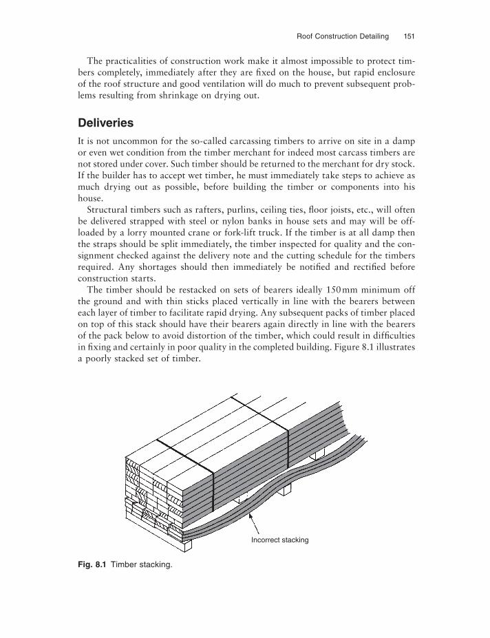
Roof Construction Detailing 151
The practicalities of construction work make it almost impossible to protect tim-bers completely, immediately after they are fixed on the house, but rapid enclosure of the roof structure and good ventilation will do much to prevent subsequent prob-lems resulting from shrinkage on drying out.
DeliveriesIt is not uncommon for the so-called carcassing timbers to arrive on site in a damp or even wet condition from the timber merchant for indeed most carcass timbers are not stored under cover. Such timber should be returned to the merchant for dry stock. If the builder has to accept wet timber, he must immediately take steps to achieve as much drying out as possible, before building the timber or components into his house.
Structural timbers such as rafters, purlins, ceiling ties, fl oor joists, etc., will often be delivered strapped with steel or nylon banks in house sets and may will be off-loaded by a lorry mounted crane or fork-lift truck. If the timber is at all damp then the straps should be split immediately, the timber inspected for quality and the con-signment checked against the delivery note and the cutting schedule for the timbers required. Any shortages should then immediately be notifi ed and rectifi ed before construction starts.
The timber should be restacked on sets of bearers ideally 150 mm minimum off the ground and with thin sticks placed vertically in line with the bearers between each layer of timber to facilitate rapid drying. Any subsequent packs of timber placed on top of this stack should have their bearers again directly in line with the bearers of the pack below to avoid distortion of the timber, which could result in difficulties in fi xing and certainly in poor quality in the completed building. Figure 8.1 illustrates a poorly stacked set of timber.
Fig. 8.1 Timber stacking.
Incorrect stacking
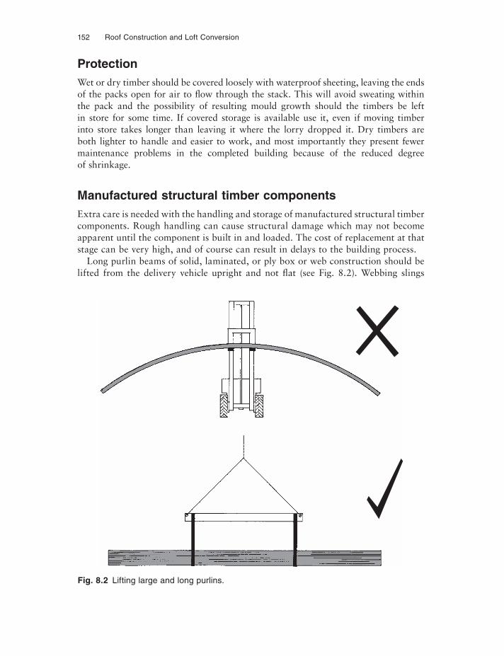
152 Roof Construction and Loft Conversion
ProtectionWet or dry timber should be covered loosely with waterproof sheeting, leaving the ends of the packs open for air to flow through the stack. This will avoid sweating within the pack and the possibility of resulting mould growth should the timbers be left in store for some time. If covered storage is available use it, even if moving timber into store takes longer than leaving it where the lorry dropped it. Dry timbers are both lighter to handle and easier to work, and most importantly they present fewer maintenance problems in the completed building because of the reduced degree of shrinkage.
Manufactured structural timber componentsExtra care is needed with the handling and storage of manufactured structural timber components. Rough handling can cause structural damage which may not become apparent until the component is built in and loaded. The cost of replacement at that stage can be very high, and of course can result in delays to the building process.
Long purlin beams of solid, laminated, or ply box or web construction should be lifted from the delivery vehicle upright and not flat (see Fig. 8.2). Webbing slings
Fig. 8.2 Lifting large and long purlins.
Roof Construction Detailing 153
from a spreader beam should be used in conjunction with either a crane, fork truck or forks on a digger and then placed on level sets of bearers and protected as described above. Major structural items should be delivered to the site as close to the actual building-in requirement as possible, thus avoiding storage. Major purlin beams, for instance, should ideally be off-loaded from the delivery vehicle by crane and hoisted directly into position in one continuous operation. This of course avoids the costs of double handling and the problems associated with storage on a restricted building site. If storage is unavoidable, then prepare the area to receive the components beforedelivery: this will speed off-loading and again save significant costs.
There has long been concern over the unsatisfactory handling, storage and protec-tion of truss rafters on many building sites. Many operatives do not appreciate the relative flexibility and fragility of the trussed rafter when being carried in its hori-zontal state, rather than in its vertical state in which, of course, it is designed to carry its working loads. The NHBC, in its standards on pitched roofs 7.2 in clause S4, sets out the correct storage and handling of the components, and the Trussed Rafter As-sociation deals with this in more depth in its technical handbook. This handbook, which was revised in 2000, has also been supplemented with a whole series of Prod-uct Data Sheets on many aspects of trussed rafter roof construction and these should be available to the reader. Full details of the Trussed Rafter Association can be found in the bibliography. British Standard 5268: Part 3 sets out standards in section 9 for handling, transportation and storage.
Most trussed rafter manufacturers deliver the components on special vehicles on which the trusses are stacked vertically – they should remain that way on site during handling and, of course, in their working position. It is the only way in which they can be considered to be a self supporting component. Flat stacking, although sometimes unavoidable, is not in the writer’s opinion considered satisfactory, and certainly requires far more attention to correct preparation of the storage area on site.
Preparation of the store areaTrussed rafter manufacturers invariably deliver the components to an agreed time schedule to the builder. For this reason there is no excuse for the site staff not being ready to receive the components. Preparation of the storage area, particularly on larger building sites, should be carried out well before delivery, and on the very larg-est sites a permanent truss storage system built as part of the site set-up (see Fig. 8.3).
A simple scaffolding frame is all that is required to support this relatively light component, with main bearers placed at approximately wall plate position and pos-sibly further bearers placed at approximately bottom chord third point positions. It is fully appreciated that more than one truss span is required on any one individual site, but careful consideration of the plans will give a satisfactory set of support posi-tions. Having set out the horizontal supports, which should be at least 300 mm off the ground, a triangulated vertical support system should be placed at the back of
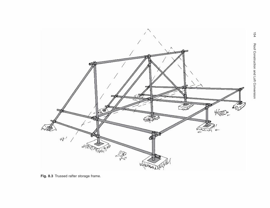
154
R
oof Construction and Loft C
onversion
Fig. 8.3 Trussed rafter storage frame.
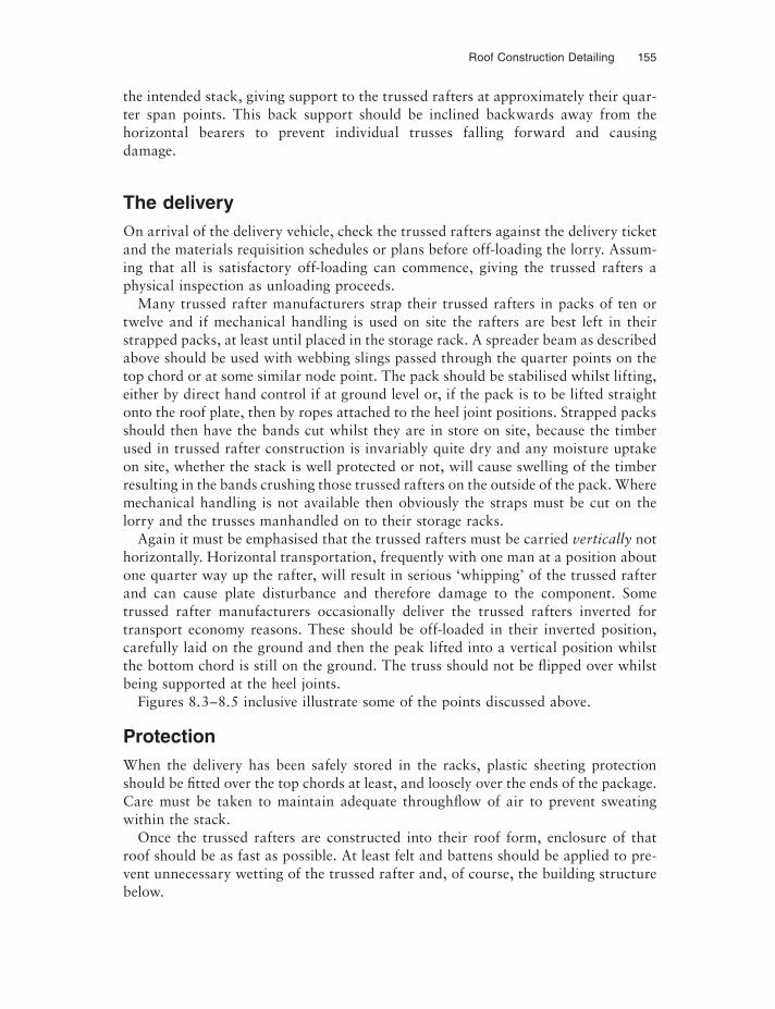
Roof Construction Detailing 155
the intended stack, giving support to the trussed rafters at approximately their quar-ter span points. This back support should be inclined backwards away from the horizontal bearers to prevent individual trusses falling forward and causing damage.
The deliveryOn arrival of the delivery vehicle, check the trussed rafters against the delivery ticket and the materials requisition schedules or plans before off-loading the lorry. Assum-ing that all is satisfactory off-loading can commence, giving the trussed rafters a physical inspection as unloading proceeds.
Many trussed rafter manufacturers strap their trussed rafters in packs of ten or twelve and if mechanical handling is used on site the rafters are best left in their strapped packs, at least until placed in the storage rack. A spreader beam as described above should be used with webbing slings passed through the quarter points on the top chord or at some similar node point. The pack should be stabilised whilst lifting, either by direct hand control if at ground level or, if the pack is to be lifted straight onto the roof plate, then by ropes attached to the heel joint positions. Strapped packs should then have the bands cut whilst they are in store on site, because the timber used in trussed rafter construction is invariably quite dry and any moisture uptake on site, whether the stack is well protected or not, will cause swelling of the timber resulting in the bands crushing those trussed rafters on the outside of the pack. Where mechanical handling is not available then obviously the straps must be cut on the lorry and the trusses manhandled on to their storage racks.
Again it must be emphasised that the trussed rafters must be carried vertically not horizontally. Horizontal transportation, frequently with one man at a position about one quarter way up the rafter, will result in serious ‘whipping’ of the trussed rafter and can cause plate disturbance and therefore damage to the component. Some trussed rafter manufacturers occasionally deliver the trussed rafters inverted for transport economy reasons. These should be off-loaded in their inverted position, carefully laid on the ground and then the peak lifted into a vertical position whilst the bottom chord is still on the ground. The truss should not be flipped over whilst being supported at the heel joints.
Figures 8.3–8.5 inclusive illustrate some of the points discussed above.
ProtectionWhen the delivery has been safely stored in the racks, plastic sheeting protection should be fi tted over the top chords at least, and loosely over the ends of the package. Care must be taken to maintain adequate throughfl ow of air to prevent sweating within the stack.
Once the trussed rafters are constructed into their roof form, enclosure of that roof should be as fast as possible. At least felt and battens should be applied to pre-vent unnecessary wetting of the trussed rafter and, of course, the building structure below.
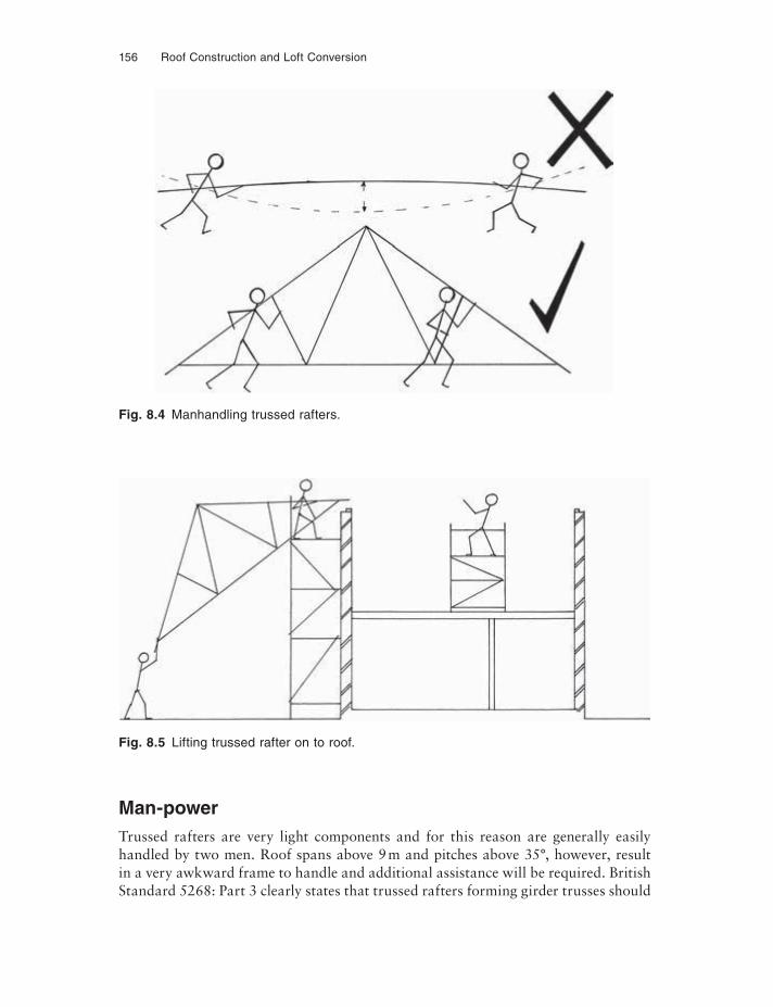
156 Roof Construction and Loft Conversion
Fig. 8.4 Manhandling trussed rafters.
Fig. 8.5 Lifting trussed rafter on to roof.
Man-powerTrussed rafters are very light components and for this reason are generally easily handled by two men. Roof spans above 9 m and pitches above 35°, however, result in a very awkward frame to handle and additional assistance will be required. British Standard 5268: Part 3 clearly states that trussed rafters forming girder trusses should
Roof Construction Detailing 157
be fabricated into their girder at the factory. This is now generally offered by the trussed rafter manufacturer to whom handling by fork trucks presents no problems, but once the girder arrives on site it may take six men to unload. The problem still remains of lifting the girder onto the building – clearly a crane should be considered to ensure safe handling of this large major structural component and to safeguard operatives from lifting excessive loads.
Similarly, the attic truss fabricated, generally from 47 mm timber and up to 3.9 m tall, presents problems; it is heavy and very unwieldy by virtue of its height. Cranes are, in the author’s opinion, essential in handling large attics and attic girders, and delivery of the components should be organised with the manufacturer to ensure crane off-loading is available to lift the components, preferably directly onto the wall plates.
PRESERVATIVE TREATMENT
Timber maintained at a moisture content below 20% is unlikely to be attacked by timber decaying fungi. However, the same does not apply to insect attack. Building legislation does not at present require structural timbers to be preservative treated (except those in flat roof constructions), with the exception of an area of England affected by the house long horn beetle. This area is defined in the Building Regula-tions. NHBC require external cladding to be treated with preservatives; this includes fascias, barge boards and timber soffits.
The various types of preservative and their application processes are set out in BS 5268: Part 5. It is not intended to enter into the detail of timber treatments. Suffice it to say that two basic types are used for constructional timbers in this country, the first being a waterborne preservative system, the second being organic solvent-borne. Their application can be by total immersion or vacuum and/or pressure depending on the type used. Brushing of these preservatives is generally not adequate to afford a high degree of protection for structural work.
CostsThe cost of timber treatment when taken in context with the overall cost of building a house is minimal, and it is therefore to be strongly recommended whether required by the regulations or not. For the traditional cut roof or those timbers site fitted to the other types of roof discussed in this book, the additional cost is approximately 20% of that of the raw material. With trussed rafters the additional cost varies be-tween approximately 5 and 10%, depending upon the size and complexity of the trussed rafter in question.
With the increased emphasis on high insulation values, the roof structure is becom-ing increasingly cold. Although the roof is now usually well ventilated the cold metal fixings, be they nail plates, truss clips or gable straps, can attract condensation which could clearly be absorbed by the timber to which they are fixed. Preservative treated timber will obviously resist any degradation which could occur. Ventilation has of
158 Roof Construction and Loft Conversion
course slightly increased the risk of insect attack in roof spaces, although incidence of this is extremely low. Experience with well ventilated roofs is relatively limited, however, the regulations requiring ventilation having been introduced only in the past few years. For this reason again it seems prudent to preserve the roof structure.
A question which had caused some concern was the possible corrosion of the gal-vanised punched metal plates used on trussed rafters, when they are used in conjunc-tion with the water-borne ‘CCA’ type preservatives. The concern was that the chemicals used in the treatment could cause the zinc in the galvanising to be oxidised, thus leaving the mild steel unprotected with the resulting risk of rusting. The Build-ing Research Establishment information paper IP 14/83, referred to earlier, contains comment on a corrosion survey carried out on trussed rafter roofs. This states ‘Thus whilst CCA does lead to more corrosion, this is still at a low level and on present evidence is unlikely to be of any structural significance’.
Whilst CCA preservatives are still available, significant changes have taken place over the past few years controlling the chemicals used in the preservation process. These changes recognise the varying requirement of the preservative depending upon the degree of fungicidal or insecticidal efficacy required. For instance, timber within ground contact externally clearly needs greater protection than a rafter which is normally dry, but a rafter is exposed to the possibility of insect attack. The likelihood of any form of attack on internal joinery is almost negligible – unless of course this is being installed in an old house conversion where furniture beetle and other insects may be present. These differing risks in exposure are defi ned as ‘Hazard Classes’ in BS EN 335-1.
Roof timbers generally fall into hazard class one (or class two in the areas of the country defi ned in the Building Regulations as ‘Hylotropes areas’, i.e. where the Longhorn beetle is still a risk to timber infestation). Hazard class two preservative treatment should also be specifi ed for timber used for timber frames, external wall and ground fl oor joists and for tile battens. This class is also required for timbers that are at risk of wetting, i.e. roof timbers where condensation could occur in rafters, and valley boards, sprockets etc. External building timbers above DPC, external joinery, and landscaping timber above ground contact fall into hazard class three, with fencing and posts falling into hazard class four. Class five covers timbers ex-posed to permanent salt water.
Whilst ‘tanalised’ timber is still available it is not the same preservative system as that known decades ago. CCA (Chromated Copper Arsenate) was first used over 70 years ago since which time it has performed exemplarily. However, the EC directive 2003/02/EC restricts the future use of CCA treated timbers to situations where skin contact by the general public is unlikely – it does not require existing CCA treated timber to be removed. This directive came into force on 30 June 2004. It is therefore important to specify ‘new’ tanalising, which is undertaken with the product Tanalith E. Another suitable product is Vacsol Aqua. Tanalith and Vacsol are registered trade names by Arch Timber Protection. For contact details see bibliography. Another well known name for timber preservation is Protim. For construction timber in housing Protim Clearchoice is the product conforming to hazard classes one, two
Roof Construction Detailing 159
and three, specifying either Protim Aqueos, a water born preservative process or Protim Drysol, an organic solvent based process. The latter provides better stability to the timber. Protim Aqueos and Protim Drysol are trade names of Protim Solignum Ltd. See bibliography for contact information.
Preservative identificationWhen preservation has been specifi ed, there is obviously a responsibility on the part of the contractor to make sure that the specification has been met. Many of the or-ganic solvent based preservatives carry a faint tracer dye (often light reddish brown) but some manufacturers use a clear preservative. With COSHH regulations now in force, much of the telltale oily smell of organic solvent preservative will have evapo-rated by the time the trusses arrive on site. These regulations require safe handling of preservative treated timber to protect operatives from the chemicals contained in the preservatives themselves. This means a delay of some 48 hours between treatment and handling the timber to manufacture the trussed rafter. Some manufacturers overcome this delay by pretreating all timber stock, but then cut ends exposing un-treated timber have to be swabbed with preservative before assembly. If specifying treated timber trussed rafters the purchaser should be aware of a slightly longer de-livery time required by some manufacturers.
Identification of organic solvent treated timber may be possible by smelling the trussed rafters, especially towards the middle of the pack as they are delivered on the vehicle; these trusses will not have evaporated quite so much solvent and will give the distinctive oily smell of the organic solvent. Alternatively, a sliver of timber cut from the corner of one of the truss components exposing a fresh surface may in-dicate treatment. Finally, if in doubt, simple preservative testing kits are available from most of the preservative manufacturers, if any doubt exists. For security it is best to specify that the trussed rafter manufacturer provides a signed certificate of treatment for the trusses in any one consignment.
The waterborne preservatives have little odour, identification is therefore more difficult but there are tests available and reference should be made to the manufac-turers of the treatment process if any doubt exists; if for instance a certificate has not been provided or in an attempt to ascertain the state of timber in an existing roof structure.
Reworking preservative treated timbersThe preservative treated timber delivered will be treated on the outside only with a limited degree of penetration depending on the process used and the species of timber. It is unlikely that the lengths delivered will be exactly those required, therefore they will have to be cut, notched, drilled or perhaps planed. Any surface change by re-working must be retreated if full protection is to be maintained. All preservative treatment processes have special compatible liquid formulations for on-site retreat-ments where appropriate, but this will depend upon the method of processing and the hazard class required.
160 Roof Construction and Loft Conversion
Application can be by liberal swabbing with brush (see ‘for your own protection’ below), or if time allows, by dipping the cut ends to give good end grain penetration. Allow to dry before handling.
Handling preservative treated timbers and environmental mattersTo perform their function of protecting timber, the preservatives have to be toxic, therefore both handling during construction (these comments do not cover handling during the preservative treatment process), and disposal of treated timber must be addressed. COSHH Regulations apply to all building sites and this should include DIY projects. Data sheets are available from the preservative manufacturers and these should be obtained and the advice carefully heeded. The contacts are in the bibliog-raphy. General guidance is given below but does not cover CCA preservatives as these are not found generally in domestic construction, unless encountered in existing timbers in conversion works.
First, the preservative treated timber should be delivered dry and free from preser-vative fl uid on the surface; if it is not it should either be returned to the supplier for suitable drying, or carefully stacked on site to allow drying before use.
For your own protection:
(1) Wear gloves.(2) Wear safety goggles when cutting and reapplying preservatives.(3) Wash work clothes separately to other wear.(4) Wear waterproof apron and footwear when applying rework preservative liquids
to cut ends, notchings and drillings etc.(5) Wear a dust mask when machine cutting preservative timbers.(6) Wash hands thoroughly before eating – even a snack.
For the protection of the environment:
(7) Small quantities (up to 0.5 tonne max) can be burnt in the open away from habit-able buildings. If burnt, the ash should be disposed of at a local authority waste site. For larger quantities (and if burning is not an option for disposal) the waste must be disposed of at a local authority registered site which is likely to cost money – do not fly-tip.
(8) Do not use the sawdust for mulching in gardens.(9) Do not use treated timber off-cuts on barbeques – food will become
contaminated.
WALL PLATES AND FIXINGS
The wall plate is the foundation for the roof. Care in setting out and bedding the plate will not only make the roof construction easier, but will result in a more sound
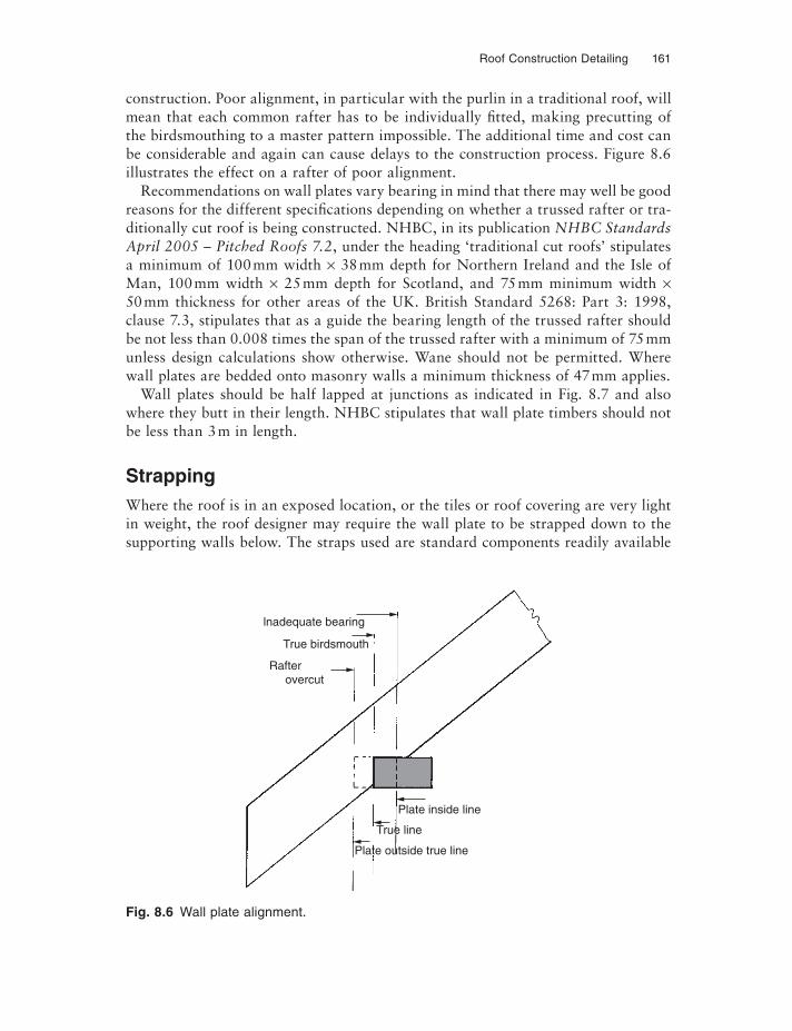
Roof Construction Detailing 161
construction. Poor alignment, in particular with the purlin in a traditional roof, will mean that each common rafter has to be individually fi tted, making precutting of the birdsmouthing to a master pattern impossible. The additional time and cost can be considerable and again can cause delays to the construction process. Figure 8.6 illustrates the effect on a rafter of poor alignment.
Recommendations on wall plates vary bearing in mind that there may well be good reasons for the different specifications depending on whether a trussed rafter or tra-ditionally cut roof is being constructed. NHBC, in its publication NHBC Standards April 2005 – Pitched Roofs 7.2, under the heading ‘traditional cut roofs’ stipulates a minimum of 100 mm width × 38 mm depth for Northern Ireland and the Isle of Man, 100 mm width × 25 mm depth for Scotland, and 75 mm minimum width ×50 mm thickness for other areas of the UK. British Standard 5268: Part 3: 1998, clause 7.3, stipulates that as a guide the bearing length of the trussed rafter should be not less than 0.008 times the span of the trussed rafter with a minimum of 75 mm unless design calculations show otherwise. Wane should not be permitted. Where wall plates are bedded onto masonry walls a minimum thickness of 47 mm applies.
Wall plates should be half lapped at junctions as indicated in Fig. 8.7 and also where they butt in their length. NHBC stipulates that wall plate timbers should not be less than 3 m in length.
StrappingWhere the roof is in an exposed location, or the tiles or roof covering are very light in weight, the roof designer may require the wall plate to be strapped down to the supporting walls below. The straps used are standard components readily available
Fig. 8.6 Wall plate alignment.
Plate inside line
True line
Plate outside true line
lnadequate bearing
True birdsmouth
Rafterovercut
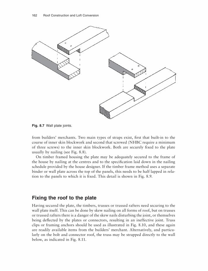
162 Roof Construction and Loft Conversion
from builders’ merchants. Two main types of straps exist, fi rst that built-in to the course of inner skin blockwork and second that screwed (NHBC require a minimum of three screws) to the inner skin blockwork. Both are securely fixed to the plate usually by nailing (see Fig. 8.8).
On timber framed housing the plate may be adequately secured to the frame of the house by nailing at the centres and to the specification laid down in the nailing schedule provided by the house designer. If the timber frame method uses a separate binder or wall plate across the top of the panels, this needs to be half lapped in rela-tion to the panels to which it is fixed. This detail is shown in Fig. 8.9.
Fixing the roof to the plateHaving secured the plate, the timbers, trusses or trussed rafters need securing to the wall plate itself. This can be done by skew nailing on all forms of roof, but on trusses or trussed rafters there is a danger of the skew nails disturbing the joint, or themselves being defl ected by the plates or connectors, resulting in an ineffective joint. Truss clips or framing anchors should be used as illustrated in Fig. 8.10, and these again are readily available items from the builders’ merchant. Alternatively, and particu-larly on the bolt and connector roof, the truss may be strapped directly to the wall below, as indicated in Fig. 8.11.
Fig. 8.7 Wall plate joints.
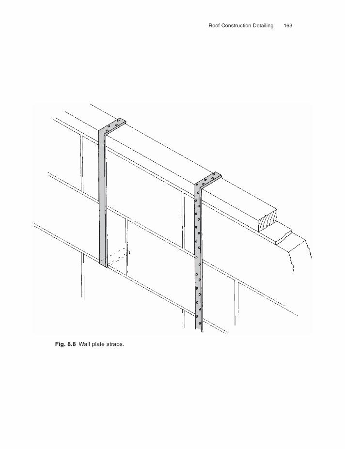
Roof Construction Detailing 163
Fig. 8.8 Wall plate straps.
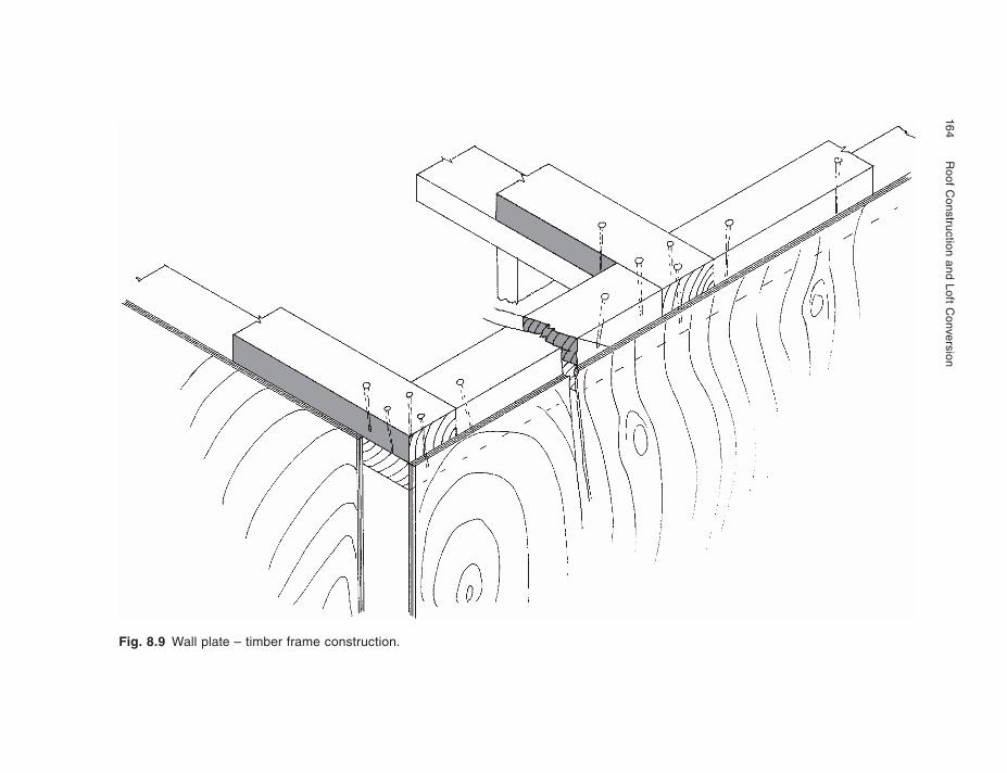
164
R
oof Construction and Loft C
onversion
Fig. 8.9 Wall plate – timber frame construction.
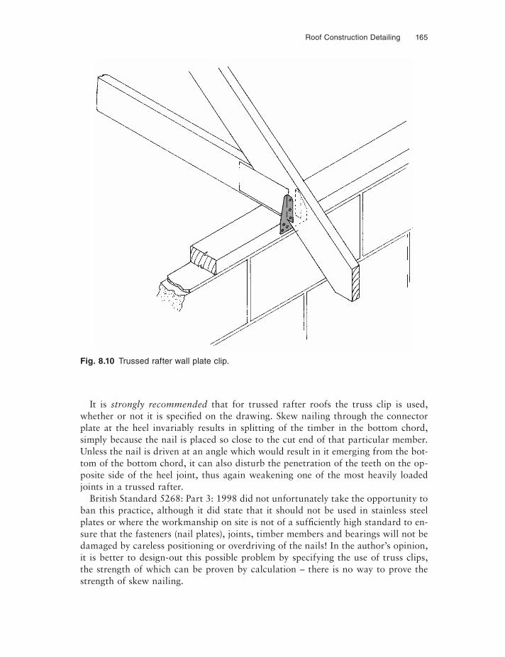
Roof Construction Detailing 165
It is strongly recommended that for trussed rafter roofs the truss clip is used, whether or not it is specifi ed on the drawing. Skew nailing through the connector plate at the heel invariably results in splitting of the timber in the bottom chord, simply because the nail is placed so close to the cut end of that particular member. Unless the nail is driven at an angle which would result in it emerging from the bot-tom of the bottom chord, it can also disturb the penetration of the teeth on the op-posite side of the heel joint, thus again weakening one of the most heavily loaded joints in a trussed rafter.
British Standard 5268: Part 3: 1998 did not unfortunately take the opportunity to ban this practice, although it did state that it should not be used in stainless steel plates or where the workmanship on site is not of a suffi ciently high standard to en-sure that the fasteners (nail plates), joints, timber members and bearings will not be damaged by careless positioning or overdriving of the nails! In the author’s opinion, it is better to design-out this possible problem by specifying the use of truss clips, the strength of which can be proven by calculation – there is no way to prove the strength of skew nailing.
Fig. 8.10 Trussed rafter wall plate clip.
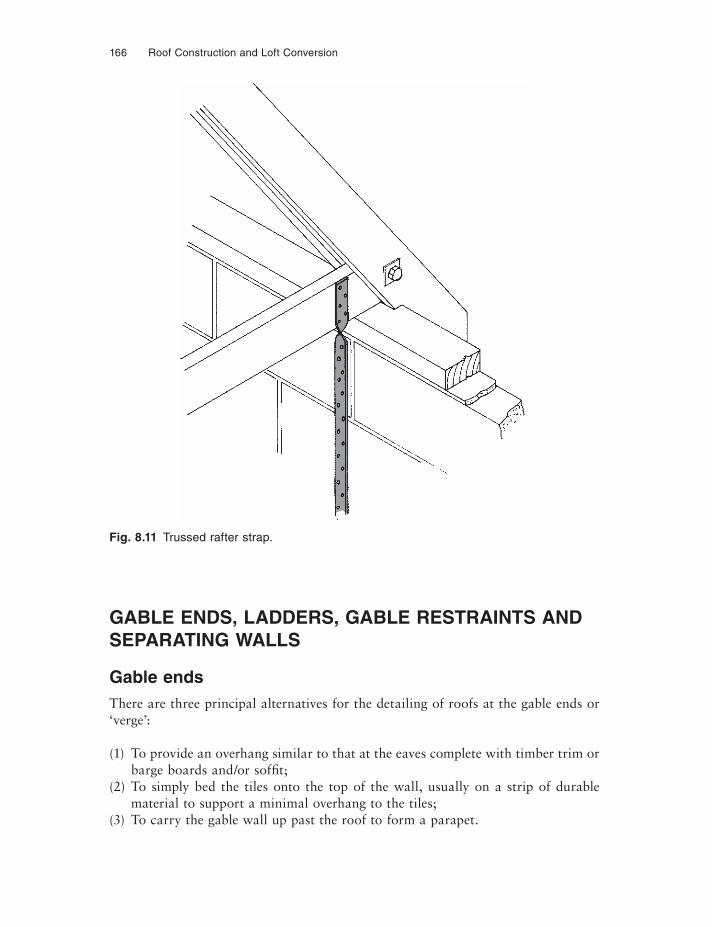
166 Roof Construction and Loft Conversion
GABLE ENDS, LADDERS, GABLE RESTRAINTS AND SEPARATING WALLS
Gable endsThere are three principal alternatives for the detailing of roofs at the gable ends or ‘verge’:
(1) To provide an overhang similar to that at the eaves complete with timber trim or barge boards and/or soffit;
(2) To simply bed the tiles onto the top of the wall, usually on a strip of durable material to support a minimal overhang to the tiles;
(3) To carry the gable wall up past the roof to form a parapet.
Fig. 8.11 Trussed rafter strap.
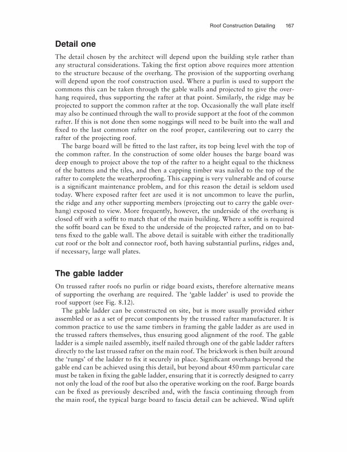
Roof Construction Detailing 167
Detail oneThe detail chosen by the architect will depend upon the building style rather than any structural considerations. Taking the first option above requires more attention to the structure because of the overhang. The provision of the supporting overhang will depend upon the roof construction used. Where a purlin is used to support the commons this can be taken through the gable walls and projected to give the over-hang required, thus supporting the rafter at that point. Similarly, the ridge may be projected to support the common rafter at the top. Occasionally the wall plate itself may also be continued through the wall to provide support at the foot of the common rafter. If this is not done then some noggings will need to be built into the wall and fixed to the last common rafter on the roof proper, cantilevering out to carry the rafter of the projecting roof.
The barge board will be fi tted to the last rafter, its top being level with the top of the common rafter. In the construction of some older houses the barge board was deep enough to project above the top of the rafter to a height equal to the thickness of the battens and the tiles, and then a capping timber was nailed to the top of the rafter to complete the weatherproofing. This capping is very vulnerable and of course is a significant maintenance problem, and for this reason the detail is seldom used today. Where exposed rafter feet are used it is not uncommon to leave the purlin, the ridge and any other supporting members (projecting out to carry the gable over-hang) exposed to view. More frequently, however, the underside of the overhang is closed off with a soffi t to match that of the main building. Where a soffi t is required the soffi t board can be fixed to the underside of the projected rafter, and on to bat-tens fixed to the gable wall. The above detail is suitable with either the traditionally cut roof or the bolt and connector roof, both having substantial purlins, ridges and, if necessary, large wall plates.
The gable ladderOn trussed rafter roofs no purlin or ridge board exists, therefore alternative means of supporting the overhang are required. The ‘gable ladder’ is used to provide the roof support (see Fig. 8.12).
The gable ladder can be constructed on site, but is more usually provided either assembled or as a set of precut components by the trussed rafter manufacturer. It is common practice to use the same timbers in framing the gable ladder as are used in the trussed rafters themselves, thus ensuring good alignment of the roof. The gable ladder is a simple nailed assembly, itself nailed through one of the gable ladder rafters directly to the last trussed rafter on the main roof. The brickwork is then built around the ‘rungs’ of the ladder to fix it securely in place. Significant overhangs beyond the gable end can be achieved using this detail, but beyond about 450 mm particular care must be taken in fixing the gable ladder, ensuring that it is correctly designed to carry not only the load of the roof but also the operative working on the roof. Barge boards can be fixed as previously described and, with the fascia continuing through from the main roof, the typical barge board to fascia detail can be achieved. Wind uplift
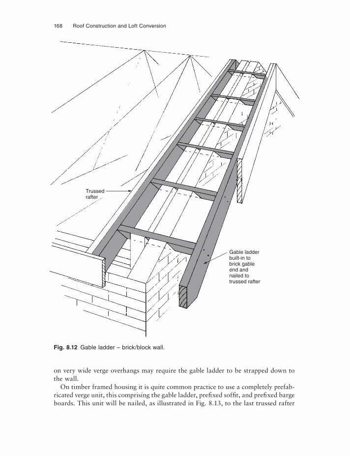
168 Roof Construction and Loft Conversion
on very wide verge overhangs may require the gable ladder to be strapped down to the wall.
On timber framed housing it is quite common practice to use a completely prefab-ricated verge unit, this comprising the gable ladder, prefixed soffit, and prefixed barge boards. This unit will be nailed, as illustrated in Fig. 8.13, to the last trussed rafter
Fig. 8.12 Gable ladder – brick/block wall.
Gable ladderbuilt-in tobrick gableend andnailed totrussed rafter
Trussedrafter
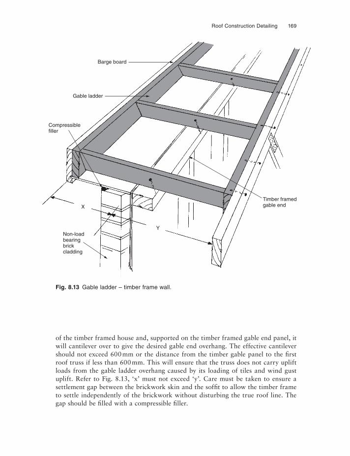
Roof Construction Detailing 169
of the timber framed house and, supported on the timber framed gable end panel, it will cantilever over to give the desired gable end overhang. The effective cantilever should not exceed 600 mm or the distance from the timber gable panel to the first roof truss if less than 600 mm. This will ensure that the truss does not carry uplift loads from the gable ladder overhang caused by its loading of tiles and wind gust uplift. Refer to Fig. 8.13, ‘x’ must not exceed ‘y’. Care must be taken to ensure a settlement gap between the brickwork skin and the soffi t to allow the timber frame to settle independently of the brickwork without disturbing the true roof line. The gap should be fi lled with a compressible fi ller.
Fig. 8.13 Gable ladder – timber frame wall.
X
YNon-loadbearingbrickcladding
Timber framedgable end
Barge board
Gable ladder
Compressiblefiller
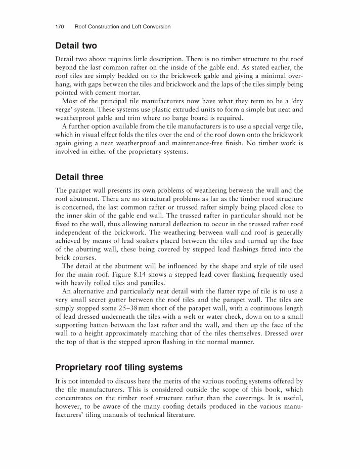
170 Roof Construction and Loft Conversion
Detail twoDetail two above requires little description. There is no timber structure to the roof beyond the last common rafter on the inside of the gable end. As stated earlier, the roof tiles are simply bedded on to the brickwork gable and giving a minimal over-hang, with gaps between the tiles and brickwork and the laps of the tiles simply being pointed with cement mortar.
Most of the principal tile manufacturers now have what they term to be a ‘dry verge’ system. These systems use plastic extruded units to form a simple but neat and weatherproof gable and trim where no barge board is required.
A further option available from the tile manufacturers is to use a special verge tile, which in visual effect folds the tiles over the end of the roof down onto the brickwork again giving a neat weatherproof and maintenance-free fi nish. No timber work is involved in either of the proprietary systems.
Detail threeThe parapet wall presents its own problems of weathering between the wall and the roof abutment. There are no structural problems as far as the timber roof structure is concerned, the last common rafter or trussed rafter simply being placed close to the inner skin of the gable end wall. The trussed rafter in particular should not be fixed to the wall, thus allowing natural deflection to occur in the trussed rafter roof independent of the brickwork. The weathering between wall and roof is generally achieved by means of lead soakers placed between the tiles and turned up the face of the abutting wall, these being covered by stepped lead fl ashings fitted into the brick courses.
The detail at the abutment will be infl uenced by the shape and style of tile used for the main roof. Figure 8.14 shows a stepped lead cover fl ashing frequently used with heavily rolled tiles and pantiles.
An alternative and particularly neat detail with the flatter type of tile is to use a very small secret gutter between the roof tiles and the parapet wall. The tiles are simply stopped some 25–38 mm short of the parapet wall, with a continuous length of lead dressed underneath the tiles with a welt or water check, down on to a small supporting batten between the last rafter and the wall, and then up the face of the wall to a height approximately matching that of the tiles themselves. Dressed over the top of that is the stepped apron fl ashing in the normal manner.
Proprietary roof tiling systems
It is not intended to discuss here the merits of the various roofing systems offered by the tile manufacturers. This is considered outside the scope of this book, which concentrates on the timber roof structure rather than the coverings. It is useful, however, to be aware of the many roofing details produced in the various manu-facturers’ tiling manuals of technical literature.
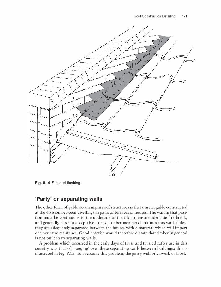
Roof Construction Detailing 171
‘Party’ or separating wallsThe other form of gable occurring in roof structures is that unseen gable constructed at the division between dwellings in pairs or terraces of houses. The wall in that posi-tion must be continuous to the underside of the tiles to ensure adequate fire break, and generally it is not acceptable to have timber members built into this wall, unless they are adequately separated between the houses with a material which will impart one hour fire resistance. Good practice would therefore dictate that timber in general is not built in to separating walls.
A problem which occurred in the early days of truss and trussed rafter use in this country was that of ‘hogging’ over these separating walls between buildings; this is illustrated in Fig. 8.15. To overcome this problem, the party wall brickwork or block-
Fig. 8.14 Stepped fl ashing.
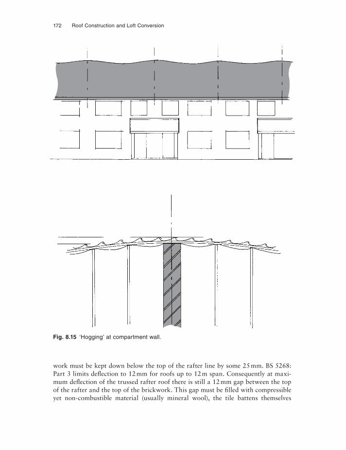
172 Roof Construction and Loft Conversion
work must be kept down below the top of the rafter line by some 25 mm. BS 5268: Part 3 limits deflection to 12 mm for roofs up to 12 m span. Consequently at maxi-mum deflection of the trussed rafter roof there is still a 12 mm gap between the top of the rafter and the top of the brickwork. This gap must be fi lled with compressible yet non-combustible material (usually mineral wool), the tile battens themselves
Fig. 8.15 ‘Hogging’ at compartment wall.
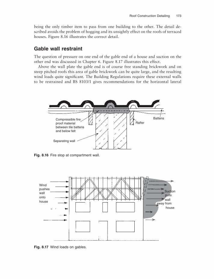
Roof Construction Detailing 173
being the only timber item to pass from one building to the other. The detail de-scribed avoids the problem of hogging and its unsightly effect on the roofs of terraced houses. Figure 8.16 illustrates the correct detail.
Gable wall restraintThe question of pressure on one end of the gable end of a house and suction on the other end was discussed in Chapter 6. Figure 8.17 illustrates this effect.
Above the wall plate the gable end is of course free standing brickwork and on steep pitched roofs this area of gable brickwork can be quite large, and the resulting wind loads quite significant. The Building Regulations require these external walls to be restrained and BS 8103/1 gives recommendations for the horizontal lateral
Fig. 8.16 Fire stop at compartment wall.
Fig. 8.17 Wind loads on gables.
Compressible fireproof materialbetween tile battensand below felt
Separating wall
RafterBattens
Windpusheswallontohouse
Suctionpullswall
away fromhouse
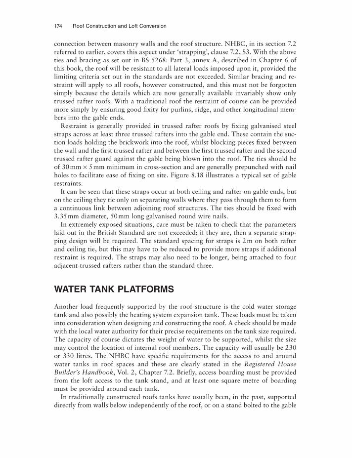
174 Roof Construction and Loft Conversion
connection between masonry walls and the roof structure. NHBC, in its section 7.2 referred to earlier, covers this aspect under ‘strapping’, clause 7.2, S3. With the above ties and bracing as set out in BS 5268: Part 3, annex A, described in Chapter 6 of this book, the roof will be resistant to all lateral loads imposed upon it, provided the limiting criteria set out in the standards are not exceeded. Similar bracing and re-straint will apply to all roofs, however constructed, and this must not be forgotten simply because the details which are now generally available invariably show only trussed rafter roofs. With a traditional roof the restraint of course can be provided more simply by ensuring good fixity for purlins, ridge, and other longitudinal mem-bers into the gable ends.
Restraint is generally provided in trussed rafter roofs by fixing galvanised steel straps across at least three trussed rafters into the gable end. These contain the suc-tion loads holding the brickwork into the roof, whilst blocking pieces fixed between the wall and the first trussed rafter and between the first trussed rafter and the second trussed rafter guard against the gable being blown into the roof. The ties should be of 30 mm × 5 mm minimum in cross-section and are generally prepunched with nail holes to facilitate ease of fixing on site. Figure 8.18 illustrates a typical set of gable restraints.
It can be seen that these straps occur at both ceiling and rafter on gable ends, but on the ceiling they tie only on separating walls where they pass through them to form a continuous link between adjoining roof structures. The ties should be fixed with 3.35 mm diameter, 50mm long galvanised round wire nails.
In extremely exposed situations, care must be taken to check that the parameters laid out in the British Standard are not exceeded; if they are, then a separate strap-ping design will be required. The standard spacing for straps is 2 m on both rafter and ceiling tie, but this may have to be reduced to provide more straps if additional restraint is required. The straps may also need to be longer, being attached to four adjacent trussed rafters rather than the standard three.
WATER TANK PLATFORMS
Another load frequently supported by the roof structure is the cold water storage tank and also possibly the heating system expansion tank. These loads must be taken into consideration when designing and constructing the roof. A check should be made with the local water authority for their precise requirements on the tank size required. The capacity of course dictates the weight of water to be supported, whilst the size may control the location of internal roof members. The capacity will usually be 230 or 330 litres. The NHBC have specific requirements for the access to and around water tanks in roof spaces and these are clearly stated in the Registered House Builder’s Handbook, Vol. 2, Chapter 7.2. Briefly, access boarding must be provided from the loft access to the tank stand, and at least one square metre of boarding must be provided around each tank.
In traditionally constructed roofs tanks have usually been, in the past, supported directly from walls below independently of the roof, or on a stand bolted to the gable
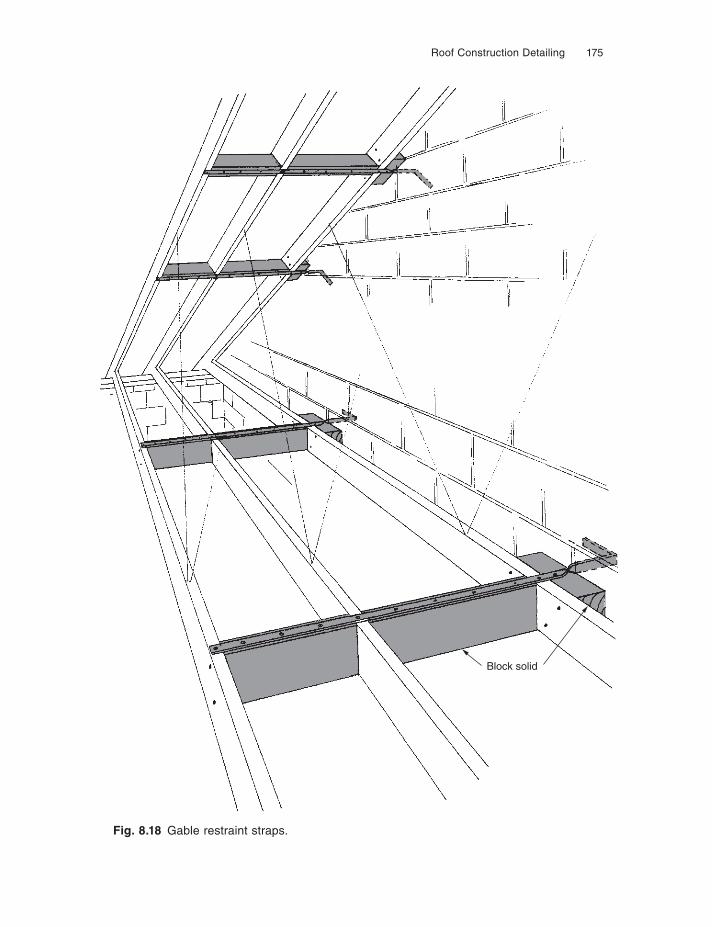
Roof Construction Detailing 175
Fig. 8.18 Gable restraint straps.
Block solid
176 Roof Construction and Loft Conversion
brickwork. If supported directly from the walls below, a detail similar to that shown in Fig. 8.19 could be used, but beams B must be designed to carry the load from the supporting walls which would themselves be replaced by beams A. The gable wall supported stand must of course have a specifically designed, probably steel bracket system which itself must be very securely fixed to the wall structure.
If the roof is to take the weight of the tanks and their supporting platform, the load will be placed invariably on the ceiling joists which are, of course, supported by binders and hangers from the purlins. All of these members will have to carry the additional weight and, moreover, careful attention must be paid to the fixings be-tween them. It will be found necessary to use bolted connections rather than simple nails to transmit the loads from one member to another. Again a tank platform simi-lar to that indicated in Fig. 8.19 could be used with beam A being supported by hangers from the purlins above.
The bolt and connector truss roofFor the bolt and connector truss roof a separate design should be prepared for the tank platforms with as much of the loads as practical being carried by the principal truss itself. The TRADA designs do not allow for tank loads and therefore any tanks carried in roofs constructed using the standard design sheets must be supported from walls below. One way of overcoming this problem is to close the centres of the prin-cipal trusses in the area of the tank thus effectively strengthening the roof in that area, enabling the structure to carry the tanks independently of walls below. Design advice must be obtained from TRADA. In such instances the design shown in Fig. 8.19 can again be used.
The trussed rafter roofIn trussed rafter roofs, BS 5268: Part 3: 2002 requires the building designer to advise the trussed rafter designer of ‘the size and position of all water tanks and other an-cillary equipment or loads to be supported on the trussed rafters’. This is clause 11.1 g. We can assume then that the trussed rafters will have been designed to carry water tanks and provided they are within prescribed limits and location within the truss, a standard tank support platform can be used.
Figure 8.19 shows a typical tank stand constructed to the guidelines laid down by BS 5268: Part 3, but for precise details of timber sizes reference should be made di-rectly to the British Standard, or to the TRA technical literature, or to any of the trussed rafter plate manufacturers’ technical brochures, or again to NHBC pitched roof clause 7.2. Depending on the tank size, it must be supported over three or four trussed rafters, always with bearers A as close as possible to the node points of the truss. A method of lowering the tank stand where restricted headroom is a problem is shown in the TRA Technical Handbook.
The question of restricted headroom must be considered when deciding upon the location of the tanks within the roof. The tank will normally be supported about the centre line of the roof truss, this generally being the largest clear void within a trussed
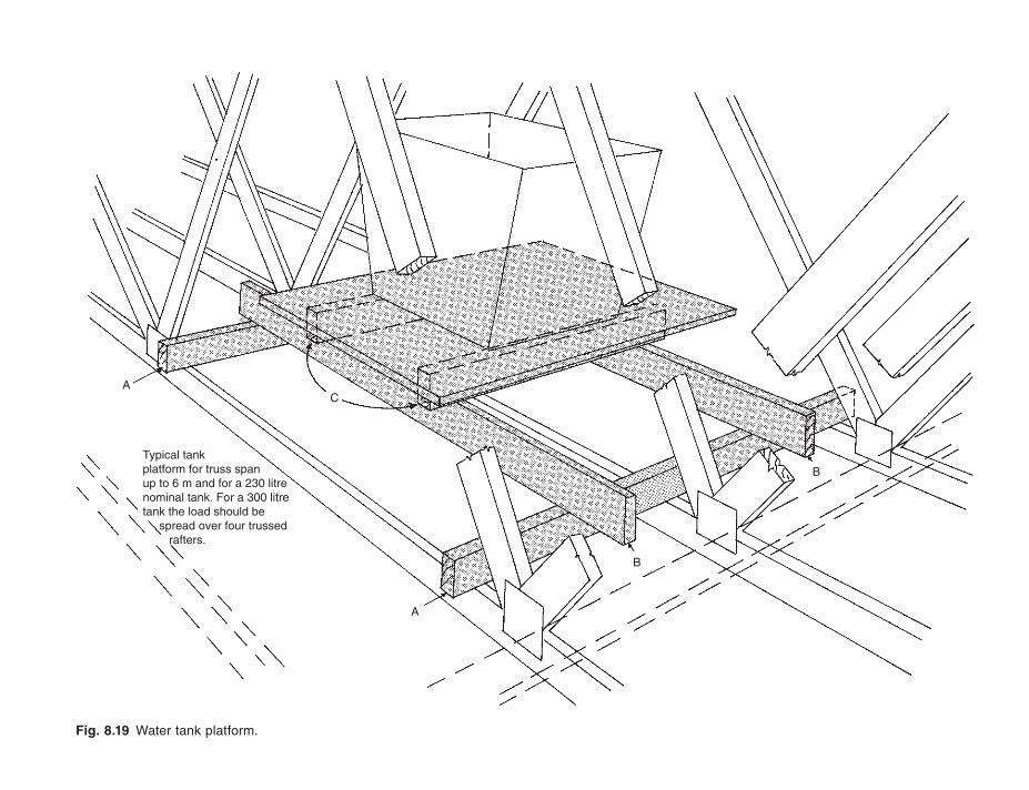
Fig. 8.19 Water tank platform.
AC
A
B
BTypical tankplatform for truss spanup to 6 m and for a 230 litrenominal tank. For a 300 litretank the load should be spread over four trussed rafters.
178 Roof Construction and Loft Conversion
rafter roof. Low pitched roofs bring their own problems of restricted headroom, likewise the numerous timber members in a hip end roof generally prevent tanks be-ing placed within the hip area. Not only must access to the tanks be considered, but also reasonable space must be left around the tank for initial installation and main-tenance thereafter. Do not forget the additional thickness of tank insulation. NHBC also advises on this subject.
General considerationsWhere showers are installed in rooms below, it is often required to raise the level of the tank as high as practical to afford head of water for the shower. The tank plat-form indicated in Fig. 8.19 can still be used, but modifi ed by building a rigid ply clad box-like structure around the above supports C. On the top of this box the normal water tank platform itself may be securely fixed. Do not nail supports B to the sides of the trussed rafter webs; they are not designed to carry such loads and the results could eventually be disastrous.
In refurbishment work, where the plumbing system is often renewed, the designer and/or installer must make sure that adequate ventilation is provided for the roof space to prevent condensation occurring on pipes to, and the tank itself. This con-densation can be a cause of seriously wetting the tank platform structure, causing degradation of both platform and supporting bearers. If chipboard is used for the platform then it should be of the moisture resisting grade.
VENTILATION OF ROOF VOIDS
The ever increasing need to conserve the energy used for home heating has led to higher insulation standards in recent years, and further improvements in these stan-dards can be anticipated in years to come. The insulation is usually placed between ceiling joists, resulting in what is known as a cold roof space, as against a warm roof space, which would be the case with insulation placed within the rafters. The fol-lowing discussion assumes a cold roof space situation.
Moisture vapour rising from the home below passes through the ceiling and insula-tion into the cold atmosphere of the roof and will, under certain conditions, condense into water on the coldest elements within the roof space. These cold elements are in-variably the metal fi xings used to construct the roof and of course, in the case of a trussed rafter roof, the nail plates used for the trussed rafter assembly itself. Clearly this wetting can lead to deterioration of the metal fi xings and, if continued for long periods, to the deterioration of the timbers if they are not fully preservative treated.
The solutionTwo possible solutions exist, at least in theory. First, prevent the moisture-laden air entering the roof space or, second ventilate the moisture-laden air before it can con-dense and cause any harm. Examining the first option, this at first seems the most
Roof Construction Detailing 179
simple method, and in theory this can be achieved by placing a vapour barrier of polythene or similar vapour proof sheeting immediately above the ceiling fi nish, yet beneath the insulation. This would contain the moisture-laden air within the building below. In practice, however, there are numerous small holes through this vapour barrier in the form of electrical services, hot and cold water services and soil and vent pipes. There is also the problem of effectively sealing joints between the sheets of polythene used. The major drawback to this option in the writer’s opinion is that a vapour barrier immediately above the ceiling fi nish effectively traps some of the vapour, and can lead to unsightly mould growth which can be extremely difficult to eradicate once it has appeared. It is virtually impossible to contain moisture within rooms such as bathrooms, shower rooms and kitchens and therefore this first option of a vapour barrier is not a practical one.
We are therefore left with the option of ventilating the roof void. The British Standard 5268: Part 3 no longer sets out minimum requirements as this is considered the responsibility of the ‘building’ designer as distinct from the roof structure de-signer. BS 5250 gives guidance on prevention of condensation in roofs. NHBC cover the subject in clause 7.2/D10, Ventilation. The Building Regulations themselves in approved document F clause f2, Condensation, also require the designer to take account of the possibility of condensation within the roof space. The TRA technical bulletin gives details of how this ventilation should be provided in conjunction with trussed rafter roofs.
Satisfactory ventilation will be provided by designing a minimum gap of 25 mm along at least two opposite sides of a roof where the pitch does not exceed 15°, or 10 mm for roof pitches above 15°. Furthermore, when a monopitch roof is being considered or a duopitch roof in excess of 20°, or 10 m span, consideration should be given to providing a further 5 mm of continuous ventilation at the ridge. Care must also be taken to identify condensation traps such as those below dormer and roof-window cills, providing some 5 mm of ventilation at those points. Do not forget to introduce ventilation above the dormer roof or roof window head, remembering also that the dormer roof itself should be provided with ventilation. There are many ways of effectively providing this ventilation, mostly via the soffi t in the form of slots or holes covered with an insect-proof gauze. Having introduced the airflow into the soffi t void, care must be taken to prevent insulation blocking the space between the rafters, thus preventing this fl ow of air into and through the roof space. In addition, therefore, some method of controlling the insulation must be introduced.
Proprietary systemsThe two leading roof tile manufacturers in this country, namely Marley and Redland, both have their own systems for providing ventilation at eaves level and at ridge roof spaces. Both systems use lightweight plastic type mouldings to provide the ventila-tion, insulation control and the necessary insect screening. Both companies produce systems where the ventilation is provided on top of the fascia and not through the soffi t by, in Redland’s case, a single plastic moulding, and in Marley’s case a set of mouldings which at one and the same time provide ventilation, support the roofing
180 Roof Construction and Loft Conversion
underlay felt to prevent ponding and control the insulation. Both systems have a ridge ventilation method which is ‘dry fixed’, meaning that it does not depend on traditional cement mortar for secure bedding.
Other companies manufacture individual ventilators and insulation controllers, the latter usually designed for use with trussed rafters at the standard 600 mm centres. All provide components complying to the necessary requirements, but careful speci-fication of the individual item is necessary to ensure that the correct air gap for the pitch being used is achieved. Figure 8.20 shows the essential features of eaves ventila-tion and insulation control.
The attic roofThe attic roof of course has three roof voids, those at either side at low level and the triangular roof void above the attic room. Airflow must again be introduced at low level, i.e. at the eaves, and allowed to flow unobstructed from the lower roof void up between the rafters to the upper roof void, where exhausting from the ridge is par-ticularly important because of the usually steep pitch nature of the attic roof.
The area of rafter which forms the sloping ceiling of the room must be carefully considered. When attic trussed rafters are used then this rafter may well be 200 mm deep which, when 100 mm of insulation is used between the rafters, should allow adequate ventilation space above the insulation from one roof void to the next. How-ever, unless the designer can be absolutely certain that the insulation will not slide down the sloping ceiling, some controls may need to be introduced to ensure that adequate ventilation space of 50 mm between each rafter is maintained.
On traditionally constructed attic roofs where the timbers may be smaller, or in the type of construction illustrated in Figs 6.19 and 7.15, the timber used for the rafters will be relatively small. To ensure that adequate insulation thickness and air space are maintained, it may be necessary to specify a minimum rafter depth of at least 175 mm, thus giving room for 100 mm of insulation, an insulation controller and a 50 mm air space. In the next section, this subject of insulation control is again highlighted in the discussion on sheet material used for stability bracing in attic roof construction.
BRACING
Any roof constructed of simple timber members or manufactured components is about as stable as a row of dominoes standing on their ends. Similarly, any pressure on the end of these components will result in a ‘domino effect’, each toppling on to the other until possibly total collapse occurs. The roof clearly has to be braced against this effect and it is not adequate to consider the brick and block gable ends satisfac-tory for this purpose. The section on gable end restraint should have emphasised this point adequately.
There are three main types of bracing to be considered:
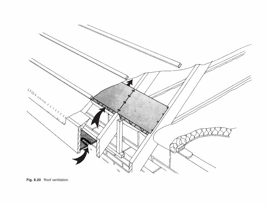
Fig. 8.20 Roof ventilation.
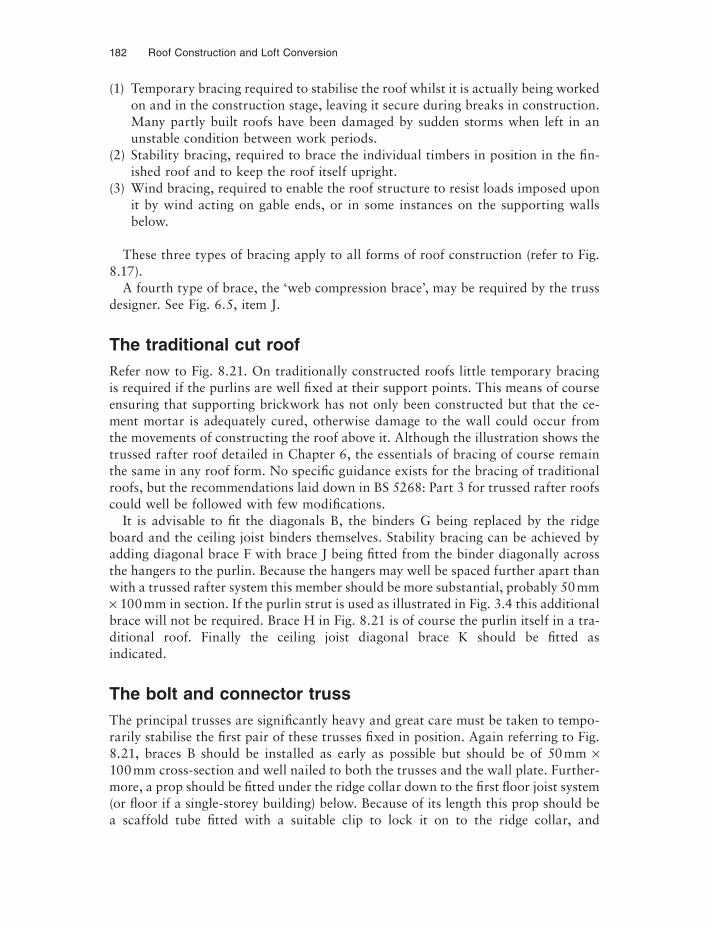
182 Roof Construction and Loft Conversion
(1) Temporary bracing required to stabilise the roof whilst it is actually being worked on and in the construction stage, leaving it secure during breaks in construction. Many partly built roofs have been damaged by sudden storms when left in an unstable condition between work periods.
(2) Stability bracing, required to brace the individual timbers in position in the fin-ished roof and to keep the roof itself upright.
(3) Wind bracing, required to enable the roof structure to resist loads imposed upon it by wind acting on gable ends, or in some instances on the supporting walls below.
These three types of bracing apply to all forms of roof construction (refer to Fig. 8.17).
A fourth type of brace, the ‘web compression brace’, may be required by the truss designer. See Fig. 6.5, item J.
The traditional cut roofRefer now to Fig. 8.21. On traditionally constructed roofs little temporary bracing is required if the purlins are well fixed at their support points. This means of course ensuring that supporting brickwork has not only been constructed but that the ce-ment mortar is adequately cured, otherwise damage to the wall could occur from the movements of constructing the roof above it. Although the illustration shows the trussed rafter roof detailed in Chapter 6, the essentials of bracing of course remain the same in any roof form. No specific guidance exists for the bracing of traditional roofs, but the recommendations laid down in BS 5268: Part 3 for trussed rafter roofs could well be followed with few modifications.
It is advisable to fi t the diagonals B, the binders G being replaced by the ridge board and the ceiling joist binders themselves. Stability bracing can be achieved by adding diagonal brace F with brace J being fi tted from the binder diagonally across the hangers to the purlin. Because the hangers may well be spaced further apart than with a trussed rafter system this member should be more substantial, probably 50 mm × 100 mm in section. If the purlin strut is used as illustrated in Fig. 3.4 this additional brace will not be required. Brace H in Fig. 8.21 is of course the purlin itself in a tra-ditional roof. Finally the ceiling joist diagonal brace K should be fitted as indicated.
The bolt and connector trussThe principal trusses are significantly heavy and great care must be taken to tempo-rarily stabilise the first pair of these trusses fixed in position. Again referring to Fig. 8.21, braces B should be installed as early as possible but should be of 50 mm ×100 mm cross-section and well nailed to both the trusses and the wall plate. Further-more, a prop should be fi tted under the ridge collar down to the first fl oor joist system (or fl oor if a single-storey building) below. Because of its length this prop should be a scaffold tube fi tted with a suitable clip to lock it on to the ridge collar, and
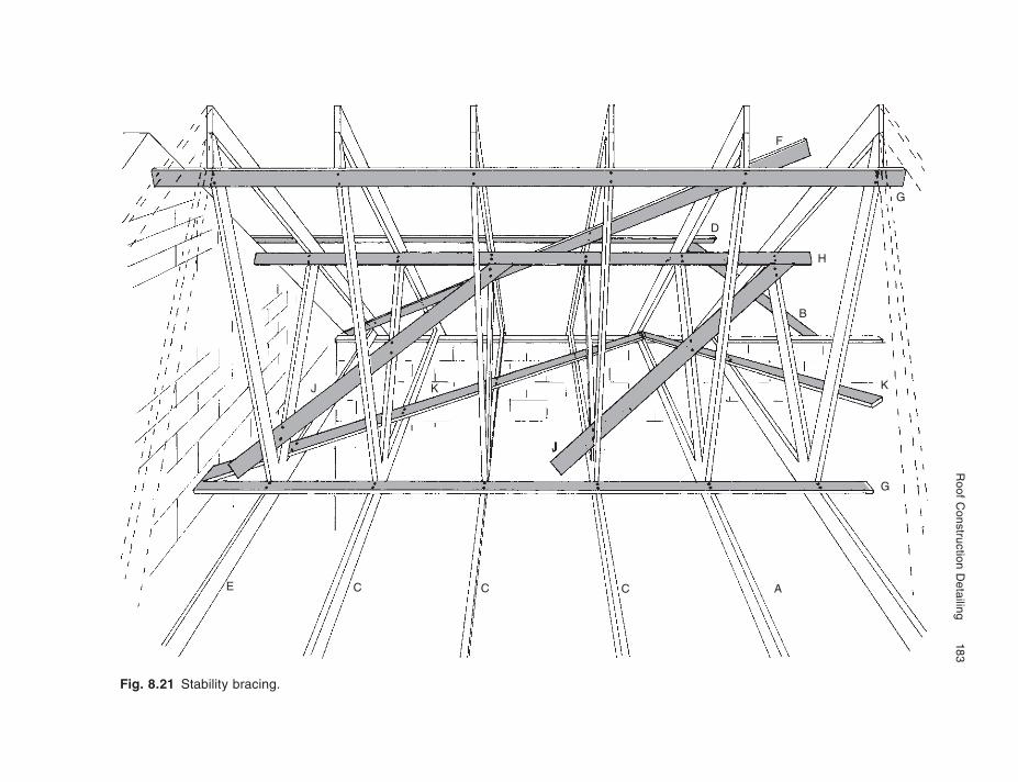
Roof C
onstruction Detailing
183
Fig. 8.21 Stability bracing.
E C C C A
J
K
B
H
G
K
G
D
F
J
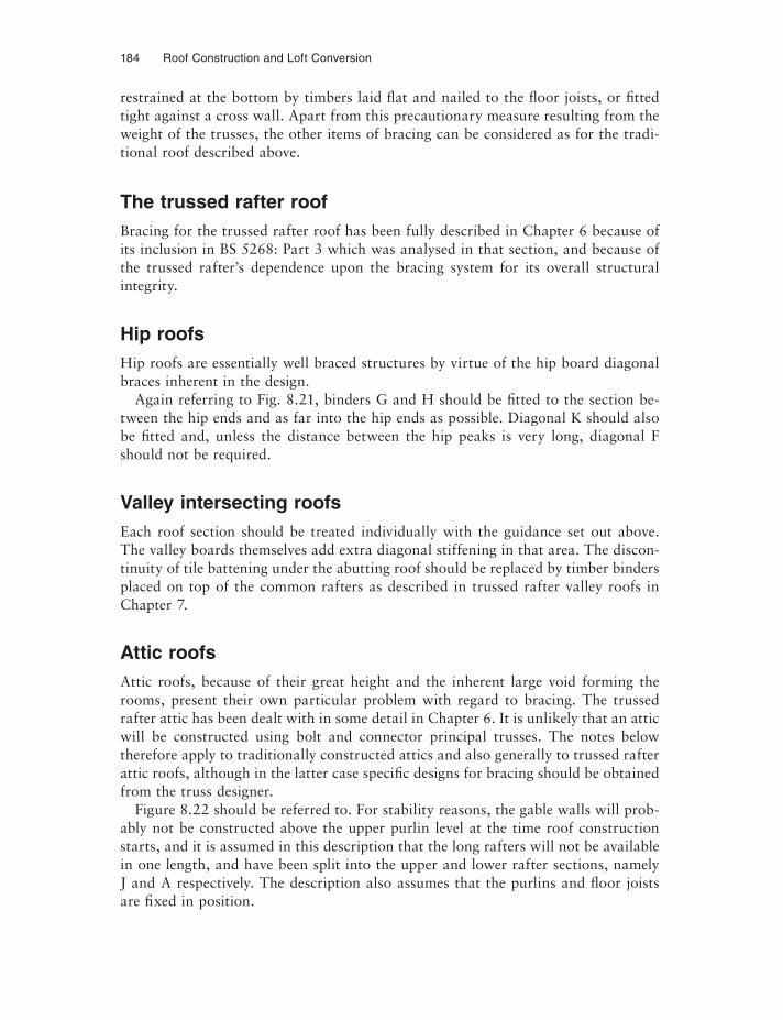
184 Roof Construction and Loft Conversion
restrained at the bottom by timbers laid flat and nailed to the fl oor joists, or fitted tight against a cross wall. Apart from this precautionary measure resulting from the weight of the trusses, the other items of bracing can be considered as for the tradi-tional roof described above.
The trussed rafter roofBracing for the trussed rafter roof has been fully described in Chapter 6 because of its inclusion in BS 5268: Part 3 which was analysed in that section, and because of the trussed rafter’s dependence upon the bracing system for its overall structural integrity.
Hip roofsHip roofs are essentially well braced structures by virtue of the hip board diagonal braces inherent in the design.
Again referring to Fig. 8.21, binders G and H should be fi tted to the section be-tween the hip ends and as far into the hip ends as possible. Diagonal K should also be fi tted and, unless the distance between the hip peaks is very long, diagonal F should not be required.
Valley intersecting roofsEach roof section should be treated individually with the guidance set out above. The valley boards themselves add extra diagonal stiffening in that area. The discon-tinuity of tile battening under the abutting roof should be replaced by timber binders placed on top of the common rafters as described in trussed rafter valley roofs in Chapter 7.
Attic roofsAttic roofs, because of their great height and the inherent large void forming the rooms, present their own particular problem with regard to bracing. The trussed rafter attic has been dealt with in some detail in Chapter 6. It is unlikely that an attic will be constructed using bolt and connector principal trusses. The notes below therefore apply to traditionally constructed attics and also generally to trussed rafter attic roofs, although in the latter case specific designs for bracing should be obtained from the truss designer.
Figure 8.22 should be referred to. For stability reasons, the gable walls will prob-ably not be constructed above the upper purlin level at the time roof construction starts, and it is assumed in this description that the long rafters will not be available in one length, and have been split into the upper and lower rafter sections, namely J and A respectively. The description also assumes that the purlins and fl oor joists are fixed in position.
Roof Construction Detailing 185
CL
J JK
BD
H
BD
GG
M
AA
EE
E E E
Fig. 8.22 Stability bracing – attic roof.
Construction should commence by fixing six of the lower rafters A from wall plate to upper purlin on both sides of the roof. Temporary diagonals B should now be fixed in place on both sides of the roof, securely fixed to each rafter passed. Collars or ceiling ties C should now be fi tted to stiffen the upper purlins. Next complete the commons to the lower part of the roof and the collars. Diagonal braces D should next be fixed to the underside of rafters A. Next fix uprights G between purlin and fl oor joist to form the walls of the room. Care should be taken to set these uprights or studs at centres appropriate to the wall covering board to be used. Diagonal H should now be fixed across the end fi ve or six uprights, nailing this to the void side of the stud, and nailed to each stud it passes.
Having stabilised each lower section of the roof, attention must now be turned to the space between the purlins, to ensure a solid structure before completing the roof to the ridge. To avoid a diagonal between the purlins on the underside of rafters A a sheet material E, which is suggested to be 9 mm or 12 mm regular sheathing ply, should be tightly fitted between the common rafters A for approximately five rafter spaces away from the gable end. This ply should be nailed to battens fixed to the side of raf-ters A at their top edge. The plywood, being fixed to the underside of these battens, will then act as insulation controller in this sloping part of the ceiling to the roof be-low, yet maintain an air space above it and below the felt underlay to the tiles. The
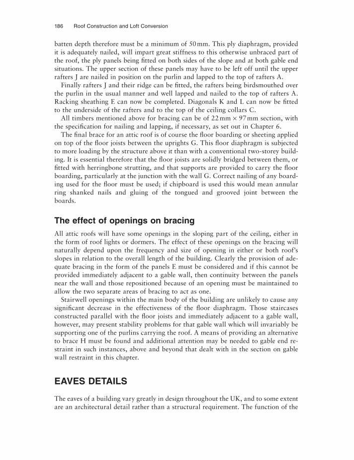
186 Roof Construction and Loft Conversion
batten depth therefore must be a minimum of 50 mm. This ply diaphragm, provided it is adequately nailed, will impart great stiffness to this otherwise unbraced part of the roof, the ply panels being fitted on both sides of the slope and at both gable end situations. The upper section of these panels may have to be left off until the upper rafters J are nailed in position on the purlin and lapped to the top of rafters A.
Finally rafters J and their ridge can be fi tted, the rafters being birdsmouthed over the purlin in the usual manner and well lapped and nailed to the top of rafters A. Racking sheathing E can now be completed. Diagonals K and L can now be fitted to the underside of the rafters and to the top of the ceiling collars C.
All timbers mentioned above for bracing can be of 22 mm × 97 mm section, with the specification for nailing and lapping, if necessary, as set out in Chapter 6.
The final brace for an attic roof is of course the fl oor boarding or sheeting applied on top of the fl oor joists between the uprights G. This fl oor diaphragm is subjected to more loading by the structure above it than with a conventional two-storey build-ing. It is essential therefore that the fl oor joists are solidly bridged between them, or fi tted with herringbone strutting, and that supports are provided to carry the floor boarding, particularly at the junction with the wall G. Correct nailing of any board-ing used for the fl oor must be used; if chipboard is used this would mean annular ring shanked nails and gluing of the tongued and grooved joint between the boards.
The effect of openings on bracingAll attic roofs will have some openings in the sloping part of the ceiling, either in the form of roof lights or dormers. The effect of these openings on the bracing will naturally depend upon the frequency and size of opening in either or both roof’s slopes in relation to the overall length of the building. Clearly the provision of ade-quate bracing in the form of the panels E must be considered and if this cannot be provided immediately adjacent to a gable wall, then continuity between the panels near the wall and those repositioned because of an opening must be maintained to allow the two separate areas of bracing to act as one.
Stairwell openings within the main body of the building are unlikely to cause any significant decrease in the effectiveness of the fl oor diaphragm. Those staircases constructed parallel with the fl oor joists and immediately adjacent to a gable wall, however, may present stability problems for that gable wall which will invariably be supporting one of the purlins carrying the roof. A means of providing an alternative to brace H must be found and additional attention may be needed to gable end re-straint in such instances, above and beyond that dealt with in the section on gable wall restraint in this chapter.
EAVES DETAILS
The eaves of a building vary greatly in design throughout the UK, and to some extent are an architectural detail rather than a structural requirement. The function of the
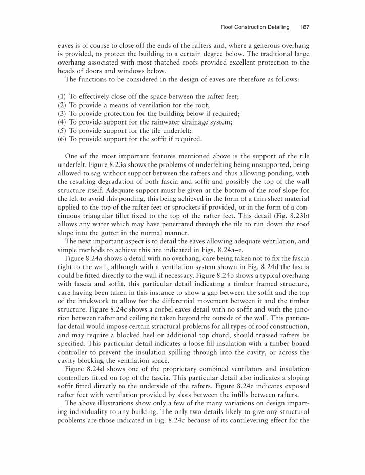
Roof Construction Detailing 187
eaves is of course to close off the ends of the rafters and, where a generous overhang is provided, to protect the building to a certain degree below. The traditional large overhang associated with most thatched roofs provided excellent protection to the heads of doors and windows below.
The functions to be considered in the design of eaves are therefore as follows:
(1) To effectively close off the space between the rafter feet;(2) To provide a means of ventilation for the roof;(3) To provide protection for the building below if required;(4) To provide support for the rainwater drainage system;(5) To provide support for the tile underfelt;(6) To provide support for the soffi t if required.
One of the most important features mentioned above is the support of the tile underfelt. Figure 8.23a shows the problems of underfelting being unsupported, being allowed to sag without support between the rafters and thus allowing ponding, with the resulting degradation of both fascia and soffi t and possibly the top of the wall structure itself. Adequate support must be given at the bottom of the roof slope for the felt to avoid this ponding, this being achieved in the form of a thin sheet material applied to the top of the rafter feet or sprockets if provided, or in the form of a con-tinuous triangular fi llet fixed to the top of the rafter feet. This detail (Fig. 8.23b) allows any water which may have penetrated through the tile to run down the roof slope into the gutter in the normal manner.
The next important aspect is to detail the eaves allowing adequate ventilation, and simple methods to achieve this are indicated in Figs. 8.24a–e.
Figure 8.24a shows a detail with no overhang, care being taken not to fix the fascia tight to the wall, although with a ventilation system shown in Fig. 8.24d the fascia could be fi tted directly to the wall if necessary. Figure 8.24b shows a typical overhang with fascia and soffit, this particular detail indicating a timber framed structure, care having been taken in this instance to show a gap between the soffi t and the top of the brickwork to allow for the differential movement between it and the timber structure. Figure 8.24c shows a corbel eaves detail with no soffi t and with the junc-tion between rafter and ceiling tie taken beyond the outside of the wall. This particu-lar detail would impose certain structural problems for all types of roof construction, and may require a blocked heel or additional top chord, should trussed rafters be specifi ed. This particular detail indicates a loose fi ll insulation with a timber board controller to prevent the insulation spilling through into the cavity, or across the cavity blocking the ventilation space.
Figure 8.24d shows one of the proprietary combined ventilators and insulation controllers fi tted on top of the fascia. This particular detail also indicates a sloping soffi t fi tted directly to the underside of the rafters. Figure 8.24e indicates exposed rafter feet with ventilation provided by slots between the infi lls between rafters.
The above illustrations show only a few of the many variations on design impart-ing individuality to any building. The only two details likely to give any structural problems are those indicated in Fig. 8.24c because of its cantilevering effect for the
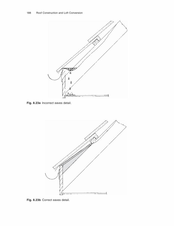
188 Roof Construction and Loft Conversion
Fig. 8.23a Incorrect eaves detail.
Fig. 8.23b Correct eaves detail.
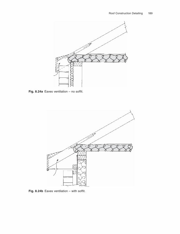
Roof Construction Detailing 189
Fig. 8.24a Eaves ventilation – no soffi t.
Fig. 8.24b Eaves ventilation – with soffi t.
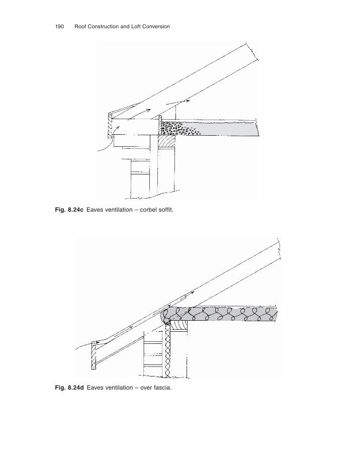
190 Roof Construction and Loft Conversion
Fig. 8.24c Eaves ventilation – corbel soffi t.
Fig. 8.24d Eaves ventilation – over fascia.
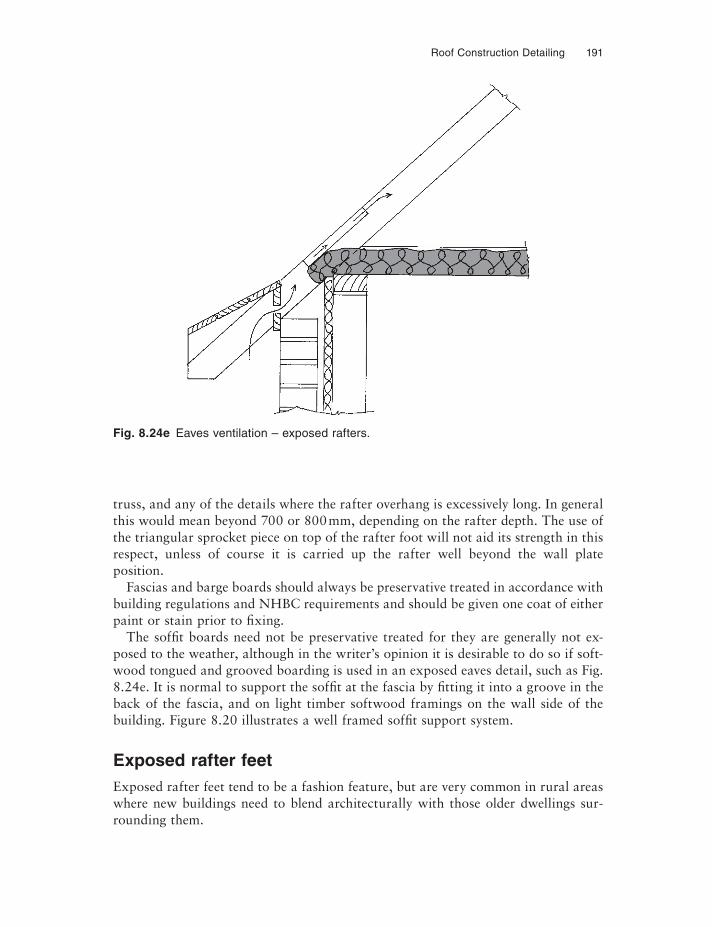
Roof Construction Detailing 191
Fig. 8.24e Eaves ventilation – exposed rafters.
truss, and any of the details where the rafter overhang is excessively long. In general this would mean beyond 700 or 800 mm, depending on the rafter depth. The use of the triangular sprocket piece on top of the rafter foot will not aid its strength in this respect, unless of course it is carried up the rafter well beyond the wall plate position.
Fascias and barge boards should always be preservative treated in accordance with building regulations and NHBC requirements and should be given one coat of either paint or stain prior to fixing.
The soffi t boards need not be preservative treated for they are generally not ex-posed to the weather, although in the writer’s opinion it is desirable to do so if soft-wood tongued and grooved boarding is used in an exposed eaves detail, such as Fig. 8.24e. It is normal to support the soffi t at the fascia by fitting it into a groove in the back of the fascia, and on light timber softwood framings on the wall side of the building. Figure 8.20 illustrates a well framed soffi t support system.
Exposed rafter feetExposed rafter feet tend to be a fashion feature, but are very common in rural areas where new buildings need to blend architecturally with those older dwellings sur-rounding them.
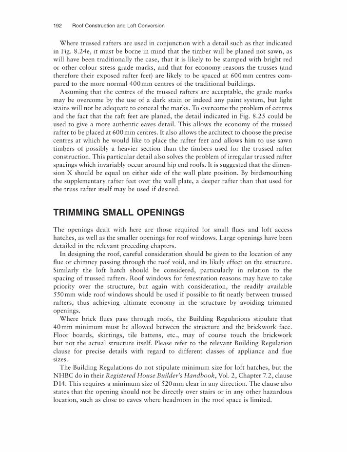
192 Roof Construction and Loft Conversion
Where trussed rafters are used in conjunction with a detail such as that indicated in Fig. 8.24e, it must be borne in mind that the timber will be planed not sawn, as will have been traditionally the case, that it is likely to be stamped with bright red or other colour stress grade marks, and that for economy reasons the trusses (and therefore their exposed rafter feet) are likely to be spaced at 600 mm centres com-pared to the more normal 400 mm centres of the traditional buildings.
Assuming that the centres of the trussed rafters are acceptable, the grade marks may be overcome by the use of a dark stain or indeed any paint system, but light stains will not be adequate to conceal the marks. To overcome the problem of centres and the fact that the raft feet are planed, the detail indicated in Fig. 8.25 could be used to give a more authentic eaves detail. This allows the economy of the trussed rafter to be placed at 600 mm centres. It also allows the architect to choose the precise centres at which he would like to place the rafter feet and allows him to use sawn timbers of possibly a heavier section than the timbers used for the trussed rafter construction. This particular detail also solves the problem of irregular trussed rafter spacings which invariably occur around hip end roofs. It is suggested that the dimen-sion X should be equal on either side of the wall plate position. By birdsmouthing the supplementary rafter feet over the wall plate, a deeper rafter than that used for the truss rafter itself may be used if desired.
TRIMMING SMALL OPENINGS
The openings dealt with here are those required for small fl ues and loft access hatches, as well as the smaller openings for roof windows. Large openings have been detailed in the relevant preceding chapters.
In designing the roof, careful consideration should be given to the location of any fl ue or chimney passing through the roof void, and its likely effect on the structure. Similarly the loft hatch should be considered, particularly in relation to the spacing of trussed rafters. Roof windows for fenestration reasons may have to take priority over the structure, but again with consideration, the readily available 550 mm wide roof windows should be used if possible to fi t neatly between trussed rafters, thus achieving ultimate economy in the structure by avoiding trimmed openings.
Where brick fl ues pass through roofs, the Building Regulations stipulate that 40 mm minimum must be allowed between the structure and the brickwork face. Floor boards, skirtings, tile battens, etc., may of course touch the brickwork but not the actual structure itself. Please refer to the relevant Building Regulation clause for precise details with regard to different classes of appliance and fl ue sizes.
The Building Regulations do not stipulate minimum size for loft hatches, but the NHBC do in their Registered House Builder’s Handbook, Vol. 2, Chapter 7.2, clause D14. This requires a minimum size of 520 mm clear in any direction. The clause also states that the opening should not be directly over stairs or in any other hazardous location, such as close to eaves where headroom in the roof space is limited.

Roof Construction Detailing 193
Fig. 8.25 Exposed rafters at eaves with sprocket.
Traditional roofsIn traditional or bolt and connector roofs, small openings may be created in either the rafters or ceiling planes by simply doubling the rafters on either side and trim-ming, as indicated in Fig. 8.26. This would be considered suitable for openings up to 1.2 m wide, and for a length the maximum distance between two purlins or purlins and plate. Larger openings must be dealt with as set out in Chapter 3.
Exposedrafters
Sprockets
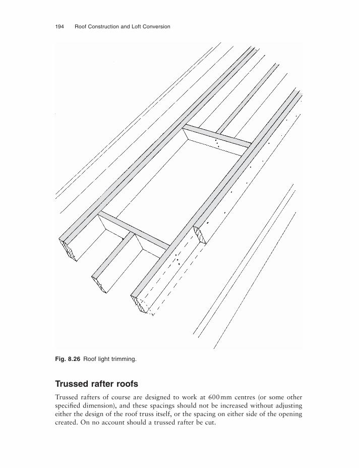
194 Roof Construction and Loft Conversion
Trussed rafter roofsTrussed rafters of course are designed to work at 600 mm centres (or some other specifi ed dimension), and these spacings should not be increased without adjusting either the design of the roof truss itself, or the spacing on either side of the opening created. On no account should a trussed rafter be cut.
Fig. 8.26 Roof light trimming.
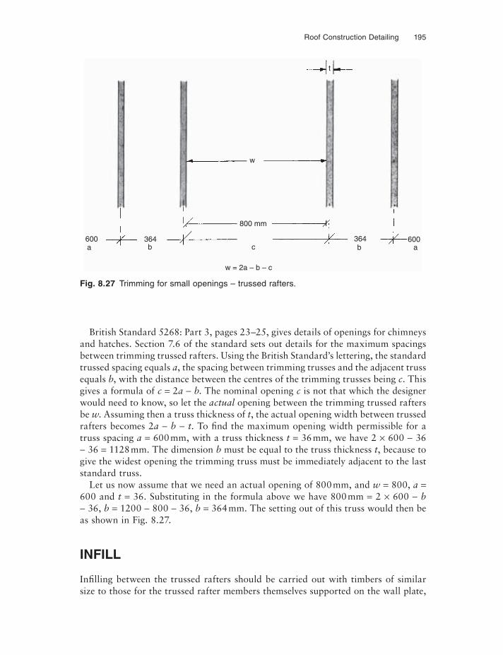
Roof Construction Detailing 195
British Standard 5268: Part 3, pages 23–25, gives details of openings for chimneys and hatches. Section 7.6 of the standard sets out details for the maximum spacings between trimming trussed rafters. Using the British Standard’s lettering, the standard trussed spacing equals a, the spacing between trimming trusses and the adjacent truss equals b, with the distance between the centres of the trimming trusses being c. This gives a formula of c = 2a − b. The nominal opening c is not that which the designer would need to know, so let the actual opening between the trimming trussed rafters be w. Assuming then a truss thickness of t, the actual opening width between trussed rafters becomes 2a − b − t. To find the maximum opening width permissible for a truss spacing a = 600 mm, with a truss thickness t = 36 mm, we have 2 × 600 − 36− 36 = 1128 mm. The dimension b must be equal to the truss thickness t, because to give the widest opening the trimming truss must be immediately adjacent to the last standard truss.
Let us now assume that we need an actual opening of 800 mm, and w = 800, a =600 and t = 36. Substituting in the formula above we have 800 mm = 2 × 600 − b− 36, b = 1200 − 800 − 36, b = 364 mm. The setting out of this truss would then be as shown in Fig. 8.27.
INFILL
Infi lling between the trussed rafters should be carried out with timbers of similar size to those for the trussed rafter members themselves supported on the wall plate,
Fig. 8.27 Trimming for small openings – trussed rafters.
600a
364b c
800 mm
w = 2a – b – c
364b
600a
w
t
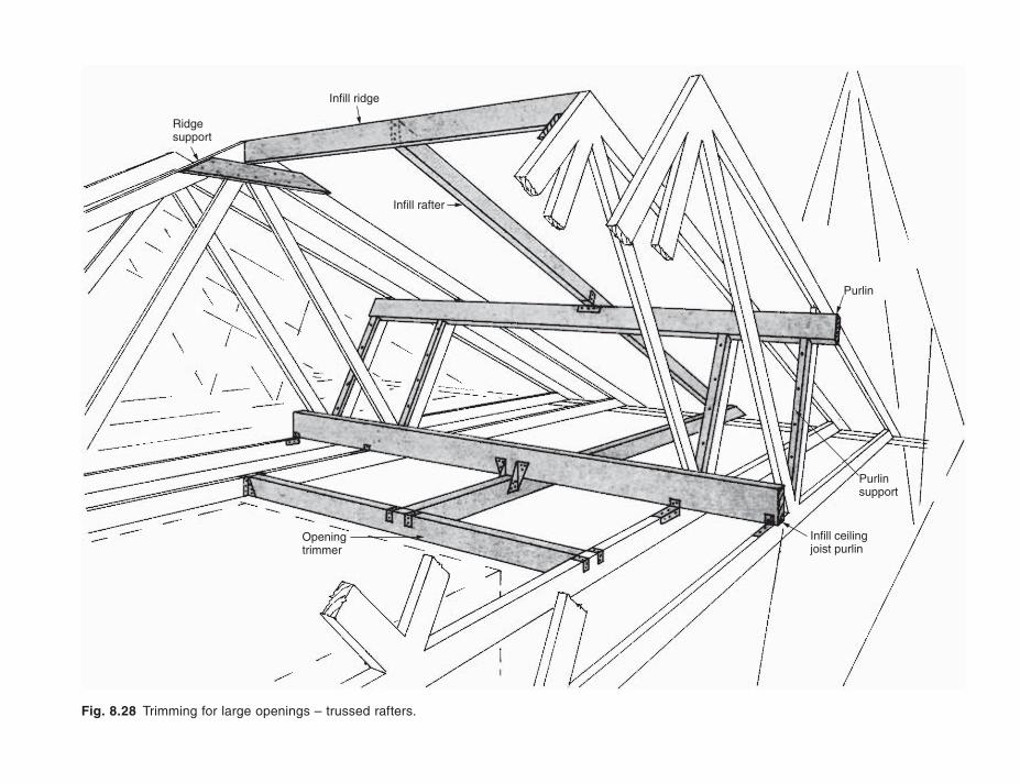
Fig. 8.28 Trimming for large openings – trussed rafters.
Infill ridge
Infill rafter
Ridgesupport
Infill ceilingjoist purlin
Openingtrimmer
Purlinsupport
Purlin
Roof Construction Detailing 197
a purlin which will effectively be a heavier piece of timber nailed to the webs in the position of brace H (Fig. 8.21), and to a timber member nailed between the trimming trusses on either side of the opening concerned. All of this assembly is carried out using galvanised nails, but for the ‘trimmers’ supporting infi ll between trusses it is strongly recommended that these are fixed to the trimming trusses with small metal framing anchors. Figure 8.28 illustrates a typical chimney infi ll situation.
CHAPTER 9
Loft Conversions
The preceding chapters of this book have dealt with roof construction methods and techniques all of which are applicable to the various forms of loft conversion. The reader interested in pursuing a loft conversion should use these preceding chapters as reference for the alternative methods of attic construction available. For instance, a conventional trussed rafter roof can be converted to an attic by the insertion of purlins and ceiling supports, followed by the removal of all of the webs, reverting the roof to a common rafter and purlin construction as described in Chapter 3. Chapter 3 also contains information on the construction of dormers which are equally applicable to conversion as to new-build. If it was found necessary to replace the roof in order to gain an attic, then Chapter 4 is very relevant as are parts of Chapter 6. The whole of Chapter 8 is also relevant for any work being undertaken on a roof structure including attic conversions.
The unused roof void has, over the past decade, become one of the most popular ‘extensions’ to the living space without encroaching on the all important, and increas-ingly expensive, land, even if there is land available. This is dramatically demon-strated by the statistic that 35% of all new trussed rafter roofs are now room-in-the-roof constructions. For reasons of cost at first sale, the attic space so formed may not be fully developed but it is effectively a built-in extension to the living space, which can later be developed to accommodate the owners’ changing accommodation requirements.
DEVELOPMENT OF THE LOFT
Utilising the roof space for living accommodation is not new. Although the very earliest simple coupled roofs would not have been strong enough to support the floor beneath, by the fifteenth century the attic had begun to appear. Very early dwellings had no chimneys as we know them: the additional height afforded by an open lofted room allowed smoke to rise above the living space to vent through a hole at the ridge.
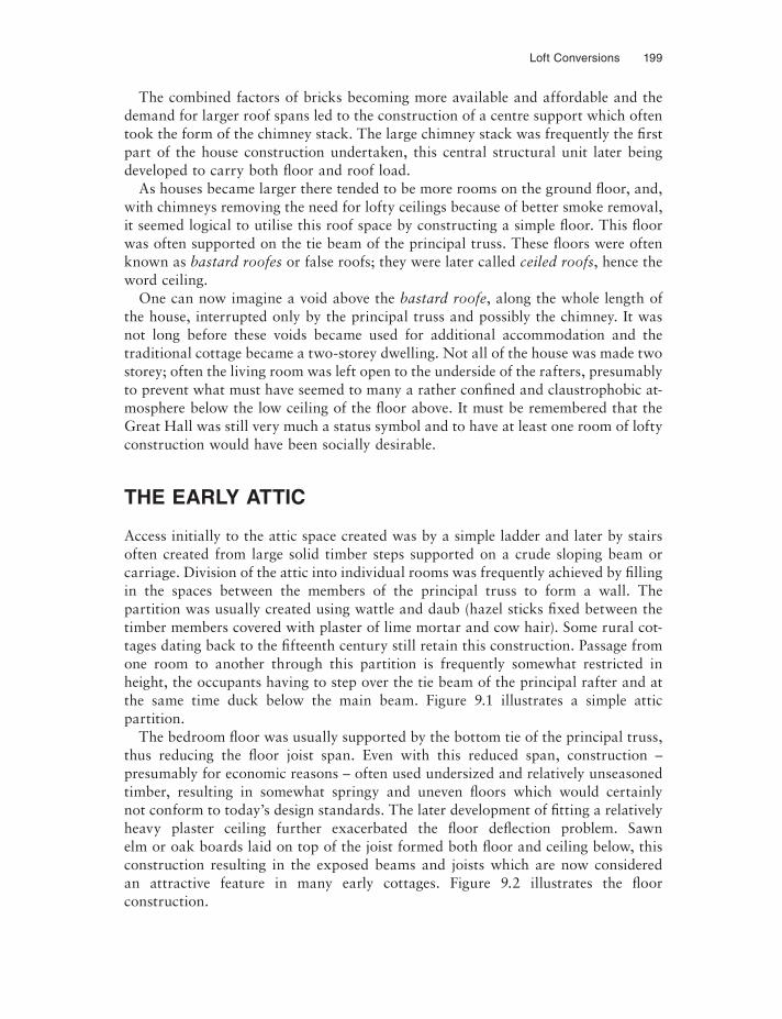
Loft Conversions 199
The combined factors of bricks becoming more available and affordable and the demand for larger roof spans led to the construction of a centre support which often took the form of the chimney stack. The large chimney stack was frequently the first part of the house construction undertaken, this central structural unit later being developed to carry both fl oor and roof load.
As houses became larger there tended to be more rooms on the ground floor, and, with chimneys removing the need for lofty ceilings because of better smoke removal, it seemed logical to utilise this roof space by constructing a simple floor. This floor was often supported on the tie beam of the principal truss. These floors were often known as bastard roofes or false roofs; they were later called ceiled roofs, hence the word ceiling.
One can now imagine a void above the bastard roofe, along the whole length of the house, interrupted only by the principal truss and possibly the chimney. It was not long before these voids became used for additional accommodation and the traditional cottage became a two-storey dwelling. Not all of the house was made two storey; often the living room was left open to the underside of the rafters, presumably to prevent what must have seemed to many a rather confined and claustrophobic at-mosphere below the low ceiling of the fl oor above. It must be remembered that the Great Hall was still very much a status symbol and to have at least one room of lofty construction would have been socially desirable.
THE EARLY ATTIC
Access initially to the attic space created was by a simple ladder and later by stairs often created from large solid timber steps supported on a crude sloping beam or carriage. Division of the attic into individual rooms was frequently achieved by fi lling in the spaces between the members of the principal truss to form a wall. The partition was usually created using wattle and daub (hazel sticks fixed between the timber members covered with plaster of lime mortar and cow hair). Some rural cot-tages dating back to the fifteenth century still retain this construction. Passage from one room to another through this partition is frequently somewhat restricted in height, the occupants having to step over the tie beam of the principal rafter and at the same time duck below the main beam. Figure 9.1 illustrates a simple attic partition.
The bedroom fl oor was usually supported by the bottom tie of the principal truss, thus reducing the fl oor joist span. Even with this reduced span, construction – presumably for economic reasons – often used undersized and relatively unseasoned timber, resulting in somewhat springy and uneven fl oors which would certainly not conform to today’s design standards. The later development of fi tting a relatively heavy plaster ceiling further exacerbated the fl oor deflection problem. Sawn elm or oak boards laid on top of the joist formed both fl oor and ceiling below, this construction resulting in the exposed beams and joists which are now considered an attractive feature in many early cottages. Figure 9.2 illustrates the floor construction.
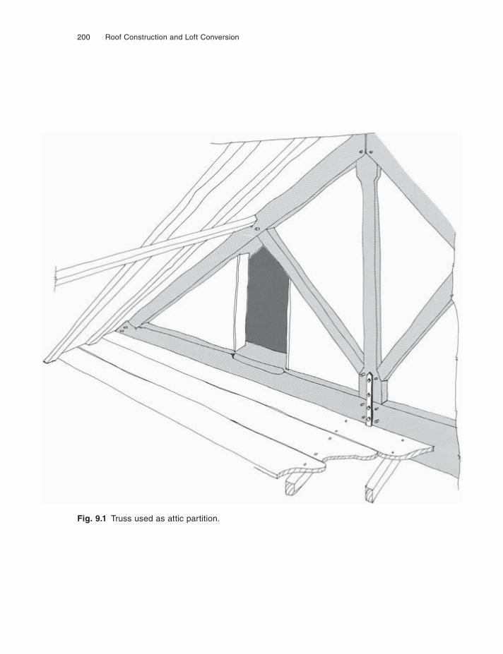
200 Roof Construction and Loft Conversion
Fig. 9.1 Truss used as attic partition.
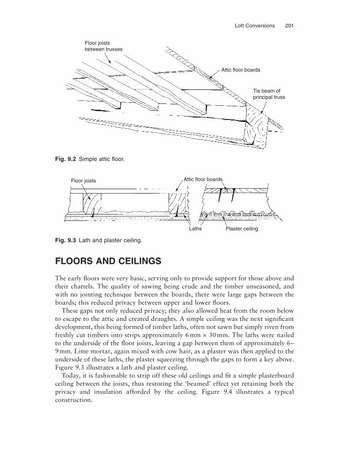
Loft Conversions 201
FLOORS AND CEILINGS
The early fl oors were very basic, serving only to provide support for those above and their chattels. The quality of sawing being crude and the timber unseasoned, and with no jointing technique between the boards, there were large gaps between the boards; this reduced privacy between upper and lower floors.
These gaps not only reduced privacy; they also allowed heat from the room below to escape to the attic and created draughts. A simple ceiling was the next significant development, this being formed of timber laths, often not sawn but simply riven from freshly cut timbers into strips approximately 6 mm × 30 mm. The laths were nailed to the underside of the fl oor joists, leaving a gap between them of approximately 6–9 mm. Lime mortar, again mixed with cow hair, as a plaster was then applied to the underside of these laths, the plaster squeezing through the gaps to form a key above. Figure 9.3 illustrates a lath and plaster ceiling.
Today, it is fashionable to strip off these old ceilings and fi t a simple plasterboard ceiling between the joists, thus restoring the ‘beamed’ effect yet retaining both the privacy and insulation afforded by the ceiling. Figure 9.4 illustrates a typical construction.
Fig. 9.2 Simple attic fl oor.
Fig. 9.3 Lath and plaster ceiling.
Floor joistsbetween trusses
Attic floor boards
Tie beam ofprincipal truss
Floor joists Attic floor boards
Laths Plaster ceiling
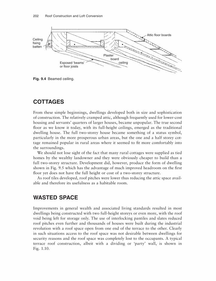
202 Roof Construction and Loft Conversion
COTTAGES
From these simple beginnings, dwellings developed both in size and sophistication of construction. The relatively cramped attic, although frequently used for lower-cost housing and servants’ quarters of larger houses, became unpopular. The true second fl oor as we know it today, with its full-height ceilings, emerged as the traditional dwelling house. The full two-storey house became something of a status symbol, particularly in the more prosperous urban areas, but the one and a half storey cot-tage remained popular in rural areas where it seemed to fi t more comfortably into the surroundings.
We should not lose sight of the fact that many rural cottages were supplied as tied homes by the wealthy landowner and they were obviously cheaper to build than a full two-storey structure. Development did, however, produce the form of dwelling shown in Fig. 9.5 which has the advantage of much improved headroom on the first fl oor yet does not have the full height or cost of a two-storey structure.
As roof tiles developed, roof pitches were lower thus reducing the attic space avail-able and therefore its usefulness as a habitable room.
WASTED SPACE
Improvements in general wealth and associated living standards resulted in most dwellings being constructed with two full-height storeys or even more, with the roof void being left for storage only. The use of interlocking pantiles and slates reduced roof pitches even further and thousands of houses were built during the industrial revolution with a roof space open from one end of the terrace to the other. Clearly in such situations access to the roof space was not desirable between dwellings for security reasons and the roof space was completely lost to the occupants. A typical terrace roof construction, albeit with a dividing or ‘party’ wall, is shown in Fig. 1.10.
Fig. 9.4 Beamed ceiling.
Ceilingfixingbatten
Exposed ‘beams’or floor joists
Attic floor boards
Plaster board ceiling
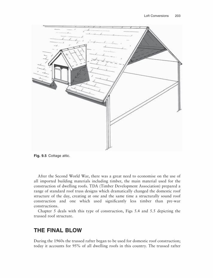
Loft Conversions 203
After the Second World War, there was a great need to economise on the use of all imported building materials including timber, the main material used for the construction of dwelling roofs. TDA (Timber Development Association) prepared a range of standard roof truss designs which dramatically changed the domestic roof structure of the day, creating at one and the same time a structurally sound roof construction and one which used significantly less timber than pre-war constructions.
Chapter 5 deals with this type of construction, Figs 5.4 and 5.5 depicting the trussed roof structure.
THE FINAL BLOW
During the 1960s the trussed rafter began to be used for domestic roof construction; today it accounts for 95% of all dwelling roofs in this country. The trussed rafter
Fig. 9.5 Cottage attic.
204 Roof Construction and Loft Conversion
placed at 600 mm centres reduces the usable roof void to a relatively small triangle in the centre of the roof (see Fig. 1.12). This area also has to accommodate the water tank platform, thus further restricting access to the roof void. The trussed rafter was certainly not designed to carry any fl oor loading, but adequately accommodates light domestic storage. Coupled with the introduction of the trussed rafter roof was the further development of double interlocking concrete tiles, which allowed even lower pitches down to 15° in some cases. Clearly, on relatively small spans the resulting roof void scarcely gave suffi cient room to allow the installation and servicing of the cold water storage tank, let alone provide useful storage. Fortunately, current archi-tectural style is towards a steeper pitched roof but only for aesthetic reasons, few housing developers taking advantage of the void so created to form additional habit-able accommodation.
EXAMINING CONVERSION POSSIBILITIES
Before any fi rm plans or budget costs can be prepared, a survey of the existing roof void must be undertaken. The survey must be accurate; approximations even at this early stage may result in later inaccuracies in the drawings, some of which could mean costly changes to planned work at a later date.
Having surveyed the roof void, it is also necessary to survey the building below accurately, right down to ground level. It is most important to establish which of the internal walls are load bearing, i.e. which have a full foundation below them, in order that the existing supporting structure can be clearly established. In relatively modern houses it should be simple to acquire plans of the building, either through deeds, a builder (if known) or the local authority building control department which approved the building originally. On older buildings, a good guide is to lift fl oor coverings to find the direction of the floor boarding; the fl oor joists will run at right angles to the fl oor boarding and the walls onto which the fl oor joists are supported will be load bearing. Partition walls between rooms on the upper fl oors may not be of load bear-ing construction and this must be clearly established before considering them for possible support for the new fl oor to the attic.
DECISION MAKING CONSIDERATIONS
Below, and in Fig. 9.6, is set out a list of critical factors regarding the potential viabil-ity of a loft conversion.
• Do we have adequate headroom?• Do we have adequate full height floor space?• Do we have enough light?• Do we have access to the new attic?• Do we have enough ventilation?
Loft Conversions 205
• Do we have enough insulation?• Do we have to relocate water storage and heating header tanks?• Does the existing roof construction have to be changed in any way?• Can the partition walls below carry the fl oor load?• Do we need planning permission?• Do we need Building Regulation permission?
Because there are numerous roof types and shapes, and houses or bungalows can be detached, semi-detached or part of a terrace, and numerous other variables, it is impossible to give instant guidance on the suitability for any individual set of cir-cumstances. For this reason an attempt has been made on the flow chart to help with the decision on whether or not an attic conversion is possible.
TYPICAL ROOF TYPES
The terraceThe roof void in a typical terraced house is illustrated in Fig. 3.1; the distance between the party or compartment walls, i.e. those dividing the houses, is often relatively small and there are frequently load bearing internal walls to be found on the ground fl oor, supporting the first fl oor joists. As can be seen from the figure, by removing the ‘collars’ a useful room void would be achieved. The collar is, of course, there to tie the rafters together by stiffening the purlins and bracing the rafters. If the collar is removed some alternative restraint must be found. If room height is adequate, extra collars could be fi tted to act as attic ceiling joists and to lighten the load on the pur-lins; an additional ridge purlin can be fi tted, supported on steel shoes built into the party wall. It should be noted at this point that in some terraces no party wall will be found as has been stated earlier, and if this is the case then one must be constructed using methods adequate to provide both fi re and sound performance to the adjoining properties.
Traditional hip and valley roofsTraditionally constructed hip roofs will generally be of substantial construction, but they frequently defy engineering analysis to prove their stability. Traditionally, much reliance was placed on ‘tosh’ or ‘skew’ nailing, something the engineer is unable to prove but the passage of time has proven to work surprisingly well (see Fig. 9.7).
The hip void will be formed in a way similar to that illustrated in Fig. 3.6, and in most cases the purlins will be supported from a load bearing wall below. However, it is not uncommon to find the purlins actually giving little support to rafters except to bind them together; in such instances the rafters are actually the only support for the roof often using the hip rafters as main supporting members. To provide an ade-quate width to the loft room it may be necessary to consider removal of some of the purlins in these traditionally constructed roofs and this will be dealt with later in Chapter 12, ‘Solutions’.
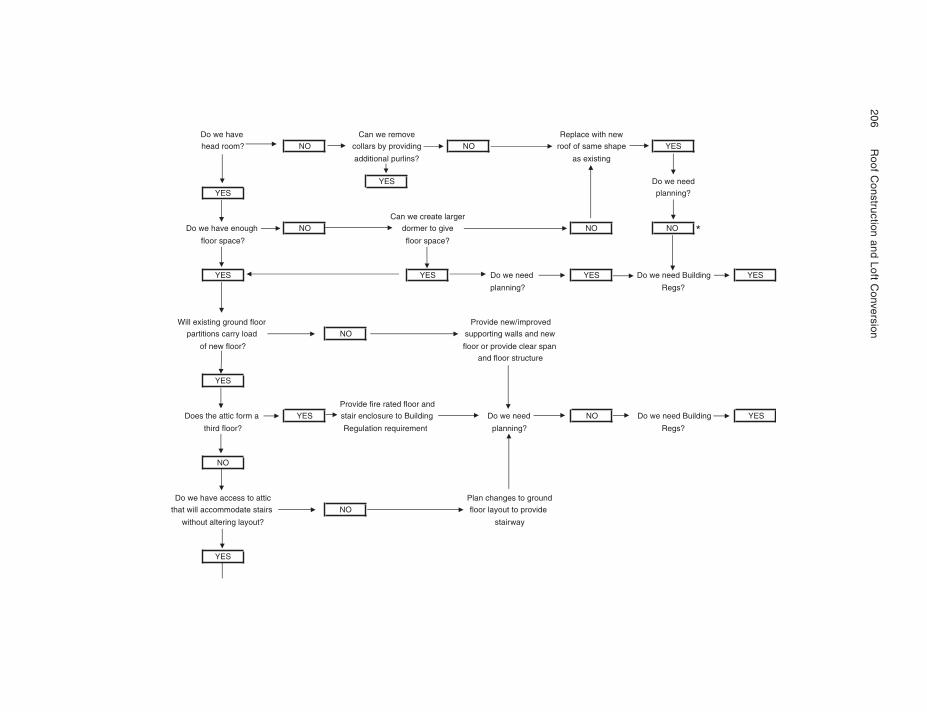
206
R
oof Construction
and Loft Conversion
wenhtiwecalpeRevomerewnaCevahewoD
SEYepahsemasfofoorONgnidivorpybsrallocON?moordaeh
gnitsixesa?snilruplanoitidda
YES Do we need
YES planning?
Can we create larger
ONONevigotremrodONhguoneevahewoD *?ecapsroolf?ecapsroolf
SEYBuildingdeenewoDSEYdeenewoDSEYSEY
?sgeR?gninnalp
devorpmi/wenedivorProolfdnuorggnitsixelliW
s and newllawgnitroppusONdaolyrracsnoititrap
napsraelcedivorproroolf?roolfwenfo
and floor structure
YES
Provide fire rated floor and
Does the attic form a YES stair enclosure to Building Do we need NO Do we need Building
?sgeR?gninnalptnemeriuqernoitalugeR?roolfdriht
NO
dnuorgotsegnahcnalPcittaotsseccaevahewoD
edivorpottuoyalroolfONsriatsetadommoccalliwtaht
yawriats?tuoyalgniretlatuohtiw
YES
YES
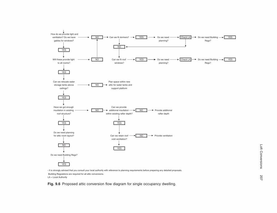
Loft Conversions
207
Fig. 9.6 Proposed attic conversion fl ow diagram for single occupancy dwelling.
How do we provide light and
ventilation? Do we have NO Can we fit dormers? YES Do we need Check LA Do we need Building YES
gables for windows? ?sgeR?gninnalp
NO
YES
Will these provide light NO Can we fit roof YES Do we need Check LA Do we need Building YES
?sgeR?gninnalp?swodniw?smoorllaot
YES
wennihtiwecapsnalPretawetacolerewnaC
andsknatretawrofcittaONevobasknategarots
mroftalptroppus?sgniliec
YES
edivorpewnaChguonetogewevaH
insullation in existing NO additional insullation NO Provide additional
htpedretfar?htpedretfargnitsixenihtiw?erutcurtsfoor
SEYSEY
Do we need planning
noitalitnevedivorPONfoorniaterewnaC?tuoyalmoorcittarof
void ventilation?
NO
YES
Do we need Building Regs?
YES
* It is strongly advised that you consult your local authority with reference to planning requirements before preparing any detailed proposals.
Building Regulations are required for all attic conversions.
LA = Local Authority
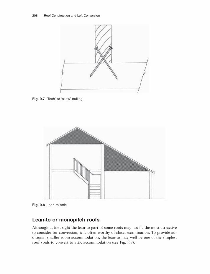
208 Roof Construction and Loft Conversion
Fig. 9.7 ‘Tosh’ or ‘skew’ nailing.
Fig. 9.8 Lean-to attic.
Lean-to or monopitch roofsAlthough at first sight the lean-to part of some roofs may not be the most attractive to consider for conversion, it is often worthy of closer examination. To provide ad-ditional smaller room accommodation, the lean-to may well be one of the simplest roof voids to convert to attic accommodation (see Fig. 9.8).
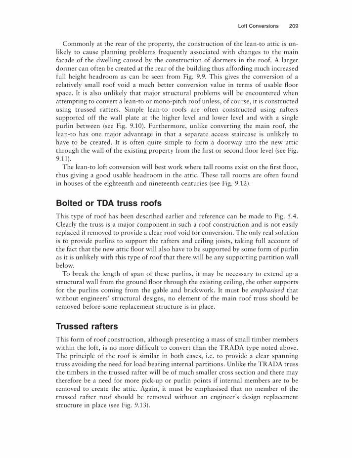
Loft Conversions 209
Commonly at the rear of the property, the construction of the lean-to attic is un-likely to cause planning problems frequently associated with changes to the main facade of the dwelling caused by the construction of dormers in the roof. A larger dormer can often be created at the rear of the building thus affording much increased full height headroom as can be seen from Fig. 9.9. This gives the conversion of a relatively small roof void a much better conversion value in terms of usable floor space. It is also unlikely that major structural problems will be encountered when attempting to convert a lean-to or mono-pitch roof unless, of course, it is constructed using trussed rafters. Simple lean-to roofs are often constructed using rafters supported off the wall plate at the higher level and lower level and with a single purlin between (see Fig. 9.10). Furthermore, unlike converting the main roof, the lean-to has one major advantage in that a separate access staircase is unlikely to have to be created. It is often quite simple to form a doorway into the new attic through the wall of the existing property from the first or second fl oor level (see Fig. 9.11).
The lean-to loft conversion will best work where tall rooms exist on the first floor, thus giving a good usable headroom in the attic. These tall rooms are often found in houses of the eighteenth and nineteenth centuries (see Fig. 9.12).
Bolted or TDA truss roofsThis type of roof has been described earlier and reference can be made to Fig. 5.4. Clearly the truss is a major component in such a roof construction and is not easily replaced if removed to provide a clear roof void for conversion. The only real solution is to provide purlins to support the rafters and ceiling joists, taking full account of the fact that the new attic floor will also have to be supported by some form of purlin as it is unlikely with this type of roof that there will be any supporting partition wall below.
To break the length of span of these purlins, it may be necessary to extend up a structural wall from the ground fl oor through the existing ceiling, the other supports for the purlins coming from the gable and brickwork. It must be emphasised that without engineers’ structural designs, no element of the main roof truss should be removed before some replacement structure is in place.
Trussed raftersThis form of roof construction, although presenting a mass of small timber members within the loft, is no more difficult to convert than the TRADA type noted above. The principle of the roof is similar in both cases, i.e. to provide a clear spanning truss avoiding the need for load bearing internal partitions. Unlike the TRADA truss the timbers in the trussed rafter will be of much smaller cross section and there may therefore be a need for more pick-up or purlin points if internal members are to be removed to create the attic. Again, it must be emphasised that no member of the trussed rafter roof should be removed without an engineer’s design replacement structure in place (see Fig. 9.13).

210 Roof Construction and Loft Conversion
LETTING IN LIGHT
This initial examination of the loft structure is not complete without consideration of whether light might be provided to the roof construction by means of dormer windows, roof windows or roof lights. Obviously on a terraced house there is not the possibility of cutting windows into the gable walls, except of course if you are fortunate enough to be at the end of the terrace. Consequently, dormers or roof lights will have to be used to provide light and ventilation to the loft conversion. These
Fig. 9.9 Improved headroom.
Additional fullheight attic floor area
Additional full height attic space
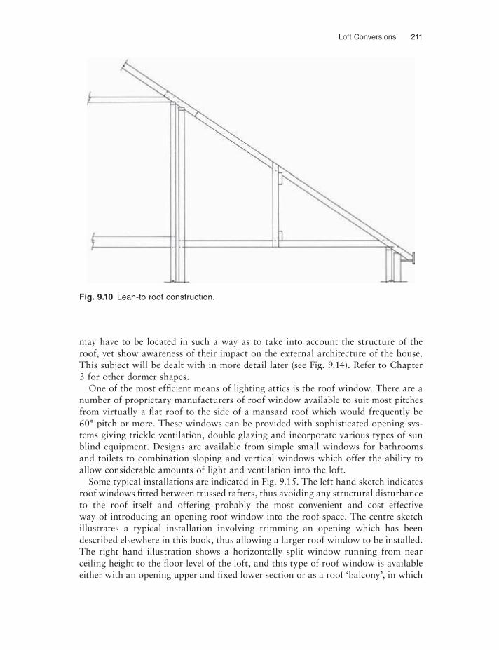
Loft Conversions 211
Fig. 9.10 Lean-to roof construction.
may have to be located in such a way as to take into account the structure of the roof, yet show awareness of their impact on the external architecture of the house. This subject will be dealt with in more detail later (see Fig. 9.14). Refer to Chapter 3 for other dormer shapes.
One of the most effi cient means of lighting attics is the roof window. There are a number of proprietary manufacturers of roof window available to suit most pitches from virtually a flat roof to the side of a mansard roof which would frequently be 60° pitch or more. These windows can be provided with sophisticated opening sys-tems giving trickle ventilation, double glazing and incorporate various types of sun blind equipment. Designs are available from simple small windows for bathrooms and toilets to combination sloping and vertical windows which offer the ability to allow considerable amounts of light and ventilation into the loft.
Some typical installations are indicated in Fig. 9.15. The left hand sketch indicates roof windows fi tted between trussed rafters, thus avoiding any structural disturbance to the roof itself and offering probably the most convenient and cost effective way of introducing an opening roof window into the roof space. The centre sketch illustrates a typical installation involving trimming an opening which has been described elsewhere in this book, thus allowing a larger roof window to be installed. The right hand illustration shows a horizontally split window running from near ceiling height to the fl oor level of the loft, and this type of roof window is available either with an opening upper and fixed lower section or as a roof ‘balcony’, in which
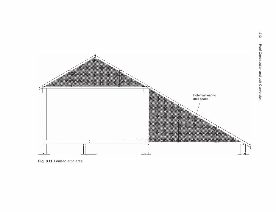
212
Roof C
onstruction and Loft Conversion
Fig. 9.11 Lean-to attic area.
Potential lean-toattic space
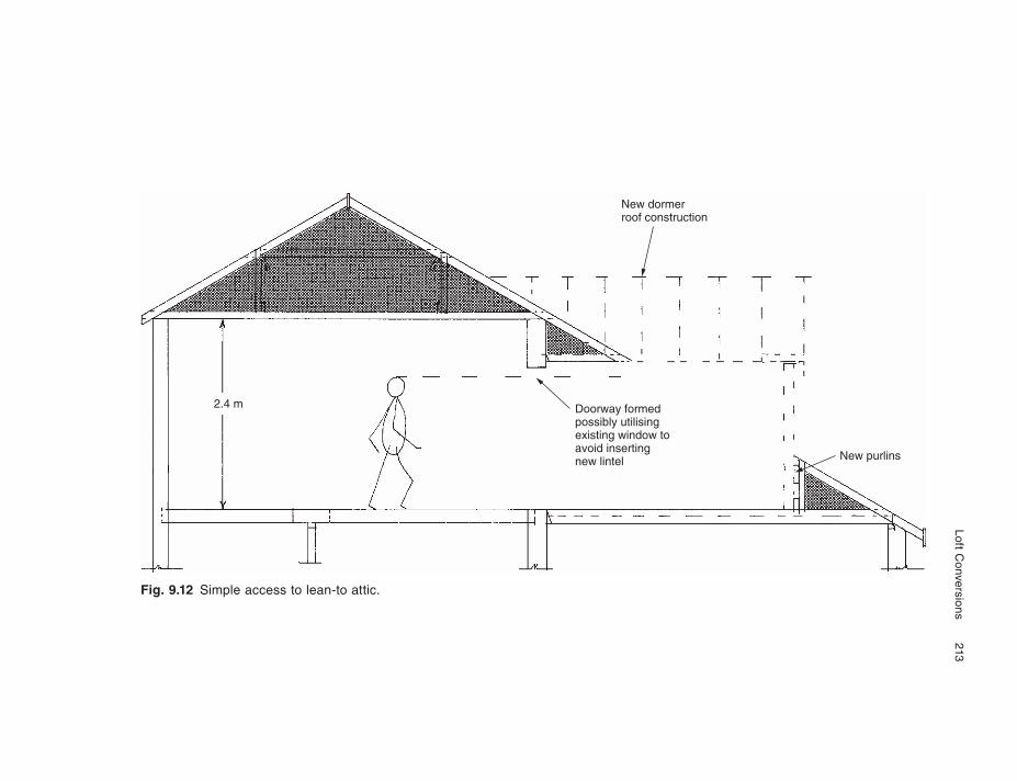
Loft Conversions
213
Fig. 9.12 Simple access to lean-to attic.
2.4 m
New dormerroof construction
New purlins
Doorway formedpossibly utilisingexisting window toavoid insertingnew lintel
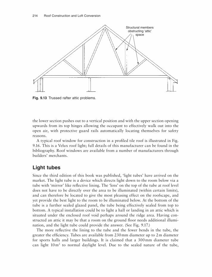
214 Roof Construction and Loft Conversion
the lower section pushes out to a vertical position and with the upper section opening upwards from its top hinges allowing the occupant to effectively walk out into the open air, with protective guard rails automatically locating themselves for safety reasons.
A typical roof window for construction in a profiled tile roof is illustrated in Fig. 9.16. This is a Velux roof light; full details of this manufacturer can be found in the bibliography. Roof windows are available from a number of manufacturers through builders’ merchants.
Light tubesSince the third edition of this book was published, ‘light tubes’ have arrived on the market. The light tube is a device which directs light down to the room below via a tube with ‘mirror’ like reflective lining. The ‘lens’ on the top of the tube at roof level does not have to be directly over the area to be illuminated (within certain limits), and can therefore be located to give the most pleasing effect on the roofscape, and yet provide the best light to the room to be illuminated below. At the bottom of the tube is a further sealed glazed panel, the tube being effectively sealed from top to bottom. A typical installation could be to light a hall or landing in an attic which is situated under the enclosed roof void perhaps around the ridge area. Having con-structed an attic it may be that a room on the ground fl oor needs additional illumi-nation, and the light tube could provide the answer. (See Fig. 9.17.)
The more reflective the lining to the tube and the fewer bends in the tube, the greater the effi ciency. Tubes are available from 230 mm diameter up to 2 m diameter for sports halls and larger buildings. It is claimed that a 300 mm diameter tube can light 10 m2 to normal daylight level. Due to the sealed nature of the tube,
Fig. 9.13 Trussed rafter attic problems.
Structural membersobstructing ‘attic’
space
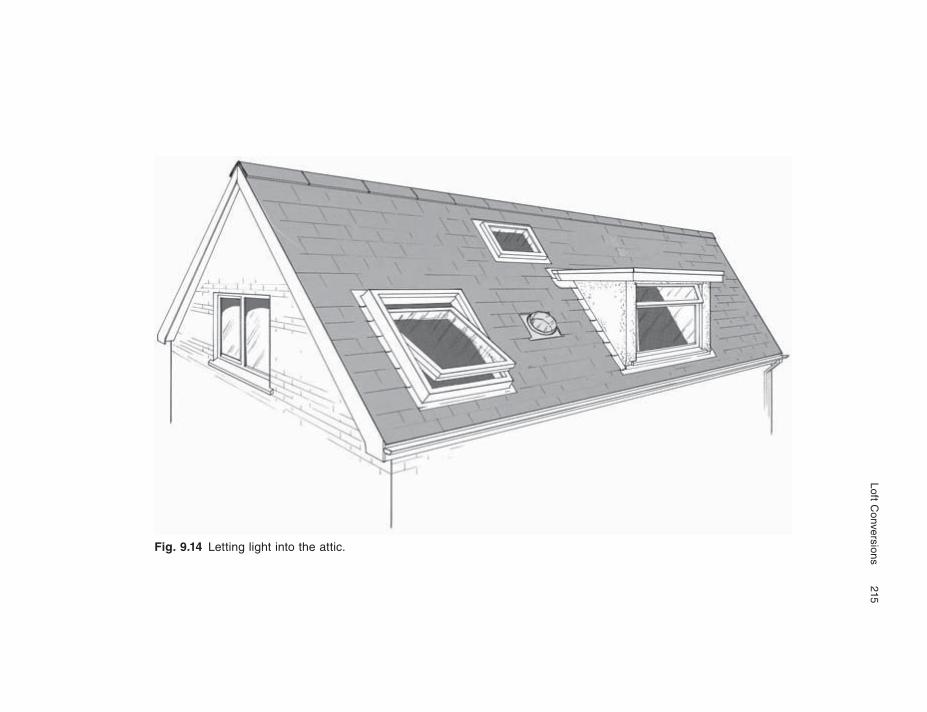
Loft Conversions
215
Fig. 9.14 Letting light into the attic.
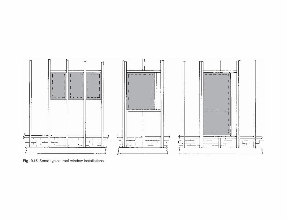
Fig. 9.15 Some typical roof window installations.
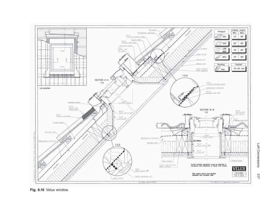
Loft Conversions
217
Fig. 9.16 Velux window.
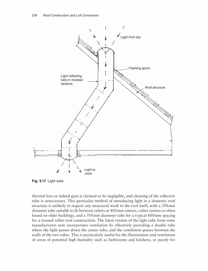
218 Roof Construction and Loft Conversion
thermal loss or indeed gain is claimed to be negligible, and cleaning of the reflective tube is unnecessary. This particular method of introducing light in a domestic roof structure is unlikely to require any structural work to the roof itself, with a 350 mm diameter tube suitable to fi t between rafters at 400 mm centres, rafter centres so often found on older buildings, and a 550 mm diameter tube for a typical 600 mm spacing for a trussed rafter roof construction. The latest version of the light tube from some manufacturers now incorporates ventilation by effectively providing a double tube where the light passes down the centre tube, and the ventilation passes between the walls of the two tubes. This is particularly useful for the illumination and ventilation of areas of potential high humidity such as bathrooms and kitchens, or purely for
Light from sky
Light reflectingtube in modularsections
Flashing apron
Roof structure
Light toroom
Fig. 9.17 Light tube.
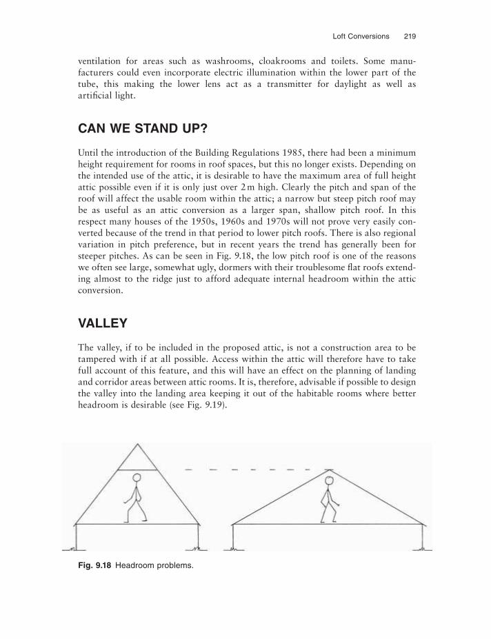
Loft Conversions 219
ventilation for areas such as washrooms, cloakrooms and toilets. Some manu-facturers could even incorporate electric illumination within the lower part of the tube, this making the lower lens act as a transmitter for daylight as well as artifi cial light.
CAN WE STAND UP?
Until the introduction of the Building Regulations 1985, there had been a minimum height requirement for rooms in roof spaces, but this no longer exists. Depending on the intended use of the attic, it is desirable to have the maximum area of full height attic possible even if it is only just over 2 m high. Clearly the pitch and span of the roof will affect the usable room within the attic; a narrow but steep pitch roof may be as useful as an attic conversion as a larger span, shallow pitch roof. In this respect many houses of the 1950s, 1960s and 1970s will not prove very easily con-verted because of the trend in that period to lower pitch roofs. There is also regional variation in pitch preference, but in recent years the trend has generally been for steeper pitches. As can be seen in Fig. 9.18, the low pitch roof is one of the reasons we often see large, somewhat ugly, dormers with their troublesome flat roofs extend-ing almost to the ridge just to afford adequate internal headroom within the attic conversion.
VALLEY
The valley, if to be included in the proposed attic, is not a construction area to be tampered with if at all possible. Access within the attic will therefore have to take full account of this feature, and this will have an effect on the planning of landing and corridor areas between attic rooms. It is, therefore, advisable if possible to design the valley into the landing area keeping it out of the habitable rooms where better headroom is desirable (see Fig. 9.19).
Fig. 9.18 Headroom problems.
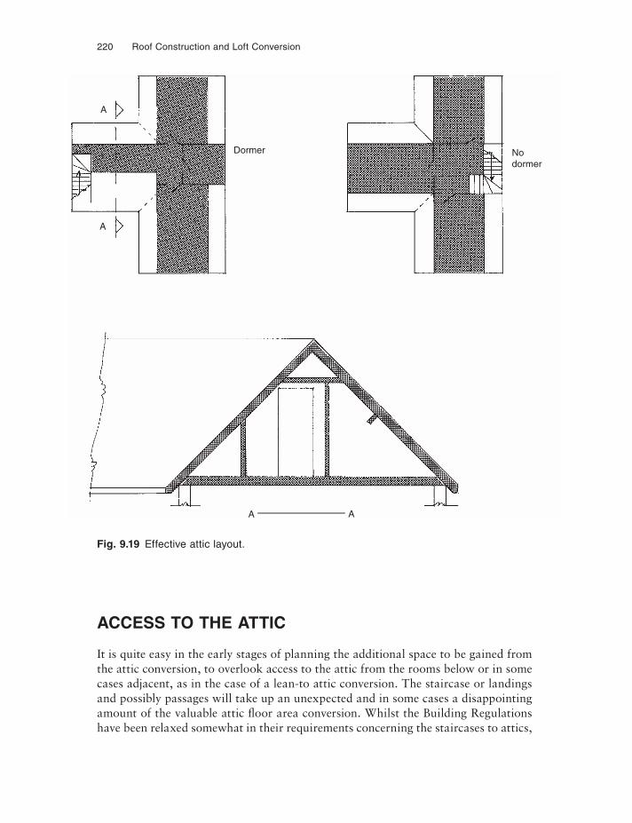
220 Roof Construction and Loft Conversion
ACCESS TO THE ATTIC
It is quite easy in the early stages of planning the additional space to be gained from the attic conversion, to overlook access to the attic from the rooms below or in some cases adjacent, as in the case of a lean-to attic conversion. The staircase or landings and possibly passages will take up an unexpected and in some cases a disappointing amount of the valuable attic fl oor area conversion. Whilst the Building Regulations have been relaxed somewhat in their requirements concerning the staircases to attics,
A
A
Dormer Nodormer
A A
Fig. 9.19 Effective attic layout.
Loft Conversions 221
allowing the loft ‘ladder’ type staircase and of course the more decorative, smaller spiral staircases, it must not be forgotten that good access is needed not just for per-sonal reasons but also to install furniture and fittings.
The small spiral staircase may provide a very interesting architectural feature within the house and indeed be very compact within its plan space requirements, but is not very practical for furniture or even for such items as baths if these are to be installed in the new conversion. It is not a very clever idea to install the bath and then fi t the staircase! This is the same as fi tting a large water storage tank in the loft and then making the trap door too small to get a replacement through.
It is strongly recommended, therefore, that a sensible sized staircase be installed for both access and safety reasons, and its impact upon the ground below must be considered. It may, for instance, be necessary to sacrifice a small ground fl oor room to provide space for the staircase and this in turn may have an effect on the planning requirements of the loft space above. The stairwell, whichever form it takes, will necessitate a reasonably large hole to be formed in the fl oor of the new loft and the structural implications of creating this must be carefully planned.
THE LAST RESORT
If all looks lost as far as a conversion of the existing loft structure is concerned for reasons of:
• excessive span for new purlins,• inadequate headroom and usable room width,• the need for too many large dormers,• problems with attic floor support,• a defective existing roof structure needing expensive repairs, or• the need to re-tile the existing roof,
then consider a complete roof replacement as it may not be so dramatic or excessively costly as may at first be thought. It may also be considerably cheaper than the alter-native possible extension to the property on the ground fl oor even if plot space and planning constraints would allow. We will deal in more detail with this possibility in Chapter 12, Solutions.
CHAPTER 10
Obligations – Visual Impact on Your Home
Any loft conversion creating living or sleeping accommodation within the roof space will of necessity need some form of window for light and ventilation. Although you may escape these requirements for a simple bathroom or toilet, even in these latter cases the need for ventilation by extractor will result in some form of additional vent pipe or grille in the roof or gable end.
Before dealing with specifi c requirements concerning planning approval for your proposed conversion, the likely impact of the alterations on the architecture of your house must be carefully considered. The type of window installation – dormer, roof window or roof light – will depend very much on what is seen to fi t in architecturally with the style of your building. It would hardly be appropriate, for instance, to install a steep-pitch dormer with a small gable on a relatively low pitched building.
Conversely, flat roof dormers will look totally out of place on a steep-pitch cottage roof (see Fig. 3.17 for dormer styles and Fig. 9.14 for further examples).
To gain the maximum amount of full-height room area within the attic, there is a temptation to settle for very large dormer windows which by their very size will have to carry flat or monopitch roofs; if this is the only solution then they should be kept to the rear of the property where they may well prove more acceptable to the planning authorities, simply because they will bring about no major visual change to the character of the main facade of the building. The degree of change to the building acceptable to the planning authorities will be dependent very much upon the building location. For instance, a loft conversion proposed in a house on a small development of architecturally similar dwellings will be viewed differently to the same proposal on a similar individual house in a street of mixed architectural styles or on an isolated country cottage.
Every effort, therefore, should be made to design new roof architecture which is in sympathy with the style of the existing property and that of the surroundings. The fenestration, i.e. location of windows in the facade, of the existing building will al-most dictate the lateral location of dormers and roof windows, and this in turn may have some effect on the positioning relative to the rooms created within the attic.
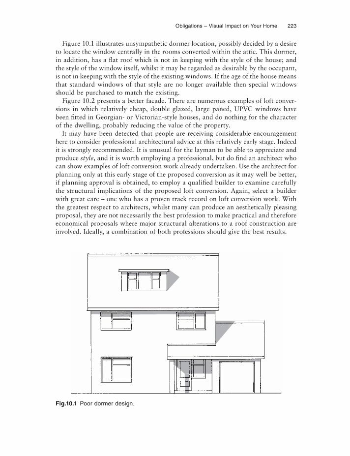
Obligations – Visual Impact on Your Home 223
Figure 10.1 illustrates unsympathetic dormer location, possibly decided by a desire to locate the window centrally in the rooms converted within the attic. This dormer, in addition, has a flat roof which is not in keeping with the style of the house; and the style of the window itself, whilst it may be regarded as desirable by the occupant, is not in keeping with the style of the existing windows. If the age of the house means that standard windows of that style are no longer available then special windows should be purchased to match the existing.
Figure 10.2 presents a better facade. There are numerous examples of loft conver-sions in which relatively cheap, double glazed, large paned, UPVC windows have been fi tted in Georgian- or Victorian-style houses, and do nothing for the character of the dwelling, probably reducing the value of the property.
It may have been detected that people are receiving considerable encouragement here to consider professional architectural advice at this relatively early stage. Indeed it is strongly recommended. It is unusual for the layman to be able to appreciate and produce style, and it is worth employing a professional, but do find an architect whocan show examples of loft conversion work already undertaken. Use the architect for planning only at this early stage of the proposed conversion as it may well be better, if planning approval is obtained, to employ a qualifi ed builder to examine carefully the structural implications of the proposed loft conversion. Again, select a builder with great care – one who has a proven track record on loft conversion work. With the greatest respect to architects, whilst many can produce an aesthetically pleasing proposal, they are not necessarily the best profession to make practical and therefore economical proposals where major structural alterations to a roof construction are involved. Ideally, a combination of both professions should give the best results.
Fig.10.1 Poor dormer design.
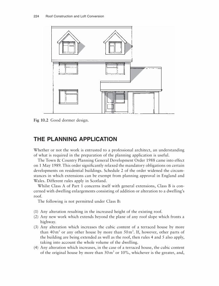
224 Roof Construction and Loft Conversion
THE PLANNING APPLICATION
Whether or not the work is entrusted to a professional architect, an understanding of what is required in the preparation of the planning application is useful.
The Town & Country Planning General Development Order 1988 came into effect on 1 May 1989. This order significantly relaxed the mandatory obligations on certain developments on residential buildings. Schedule 2 of the order widened the circum-stances in which extensions can be exempt from planning approval in England and Wales. Different rules apply in Scotland.
Whilst Class A of Part 1 concerns itself with general extensions, Class B is con-cerned with dwelling enlargements consisting of addition or alteration to a dwelling’s roof.
The following is not permitted under Class B:
(1) Any alteration resulting in the increased height of the existing roof.(2) Any new work which extends beyond the plane of any roof slope which fronts a
highway.(3) Any alteration which increases the cubic content of a terraced house by more
than 40 m3 or any other house by more than 50 m3. If, however, other parts of the building are being extended as well as the roof, then rules 4 and 5 also apply, taking into account the whole volume of the dwelling.
(4) Any alteration which increases, in the case of a terraced house, the cubic content of the original house by more than 50 m3 or 10%, whichever is the greater, and,
Fig 10.2 Good dormer design.
Obligations – Visual Impact on Your Home 225
in the case of any other type of house, by more than 70 m3 or 15%, whichever is the greater.
(5) Any alteration which increases the cubic content of any dwelling by more than 115 m3.
(6) Any alteration to a dwelling which is on:(a) National Park land,(b) land designated as a conservation area under Section 277 of the Act,(c) land controlled by the Secretary of State and Ministry of Agriculture and
Fisheries for the purpose of enhancement and protection of the natural beauty and amenity of the countryside, under the Wildlife & Countryside Act 1981.
Alterations to a roof resulting in a material alteration to the shape of the building are not covered by permitted development.
Different local authorities interpret the rules in different ways, and it is therefore well worth seeking the advice of the local authority planning offi cers concerning particular proposals and their effect upon the existing property. To proceed with even the preparation of drawings and specifications on the assumption that the pro-posed alterations to the roof structure may be exempt could prove costly. Local au-thorities are empowered to enforce reinstatement to the original if subsequent ap-proval is refused. It is likely that the planning officer’s advice will be free; the formal planning application cost is not excessive and would be money well spent if it fore-stalled a situation in which work was carried out and then identified by a local au-thority and subsequently refused.
If the proposed loft conversion work falls outside that permitted in Part B, then full planning permission must be sought.
THE STRUCTURAL IMPACT ON THE HOME
At this juncture the aspect of control on loft conversion is the Building Regulations. It is often thought by the layman that exemption under planning will mean freedom to convert; another fallacy is that once planning approval has been granted, there are no other obligations under the law and work may proceed. Planning controls concern themselves only with the visual impact on the local environment of the pro-posed conversion, whilst the Building Regulations are concerned with safety, health and welfare. Building Regulations approval is required for all structural conversion work to any building. Building Regulations approval must therefore be sought as the Regulations take into account the following aspects of the conversion:
• Structural stability;• Heating and thermal performance of the converted structure;• The installation of heating appliances;• The fire performance of the structure, particularly if the conversion creates a third
storey to the building;
226 Roof Construction and Loft Conversion
• Ventilation of the habitable rooms created;• In some cases, means of escape from the created attic rooms;• Considerations for soil and waste drainage if a bathroom, w/c or shower is
installed;• Consideration of roof rainwater run-off if the roof structure is materially
changed.
CHAPTER 11
The Conversion
MAKING A START
Having prepared rough plans to examine the roof structure’s potential, the next step is to prepare detailed plans and a specification and this must include a survey of the structure below to assess its load bearing capacity.
THE SURVEY
Obviously, accurate measurements of the existing building are important but atten-tion must be paid to the construction of walls, fl oor and roof. If drawings and speci-fications do not exist for the property to be converted then the task of recreating these must be faced, including establishing foundation location, size and depth.
It is worthwhile examining what exactly is desired of the conversion; for instance, if it is intended to create storage only rather than habitable accommodation then the loading on the fl oor below and consequently on the structure below that, may well be significantly different.
The aspects to be carefully considered are as follows:
(1) The additional load of the new floors;(2) The additional load of new walls;(3) The additional load of ceilings;(4) The additional live load of the occupants and the fittings;(5) In the case of a third fl oor, the additional weight of fire protection to walls around
stairwell;(6) In the case of the creation of flats, the additional weight of the fire-resisting
floor;(7) If the conversion is to be used as a home-based office, the additional weight of
office equipment and storage of files.
228 Roof Construction and Loft Conversion
Any loft conversion which includes habitable accommodation is likely to add around 30% to the existing foundation loading, much of this being transferred to the foundations via lintels over windows and doors which will probably only have been calculated to carry a conventional load from the roof. Consequently, any con-version will have a significant effect on the structure below and as most bungalows have the same external load bearing wall construction as a two storey house, there is unlikely to be a problem with the wall itself; attention will have to be paid, how-ever, to such items as the lintels, as explained above.
Checklist for survey• Location of foundations of existing external walls and load bearing partitions;• The type of wall construction for existing external walls and partitions;• The type and specification of existing lintels over windows and doors;• Direction and size of fl oor joists on the ground floor, if any, thus helping to estab-
lish which partitions are load bearing;• Direction, size and spacing of existing ceiling joists;• Size and spacing of existing rafters and other roof timber components;• Accurate dimensions of the existing building – not just on plan but all elevations
likely to be affected by the conversion;• Accurate heights of all rooms, thicknesses of ceiling zone, shape of roof space and
locations of any purlin supports that may be in the existing roof structure;• Accurate location within the plan of any services in the loft area, such as chimney
stacks, soil and vent pipes, water storage tanks and all service pipes. It must be remembered that some or all of these may have to be moved as part of the conversion.
PLANS AND SPECIFICATION
From the above survey produce a full set of drawings to include:
• Scale plan not less than 1 : 50 scale;• Scale elevation not less than 1 : 50 scale;• Scale section or sections; as more than one section may be necessary if the roof
shape and/or its construction changes from one part of the building to another, this should be prepared to as large a scale as possible.
All of the above to be prepared on a paper or negative which may be conveniently copied for reproducing the drawings. It must be remembered that Planning and Building Regulations consume large numbers of copies of the plans, and furthermore additional copies will be required to obtain quotations from building and/or sub-contractors for the various trades involved. Do not be surprised if, by the time the conversion is completed, 20 copies of all drawings have been produced!
Obviously the next step, using the existing fl oor plan of the fl oor below the pro-posed conversion, is to sketch on tracing paper laid over the plan the proposed loft
The Conversion 229
conversion plan. This will immediately show what is not practical and at this very early stage one of the fi rst things to be considered is access to the loft space.
Having produced a detailed and accurate set of drawings of the building, as exist-ing, and of the building as proposed in the new conversion, a fully detailed, descrip-tive specification must be prepared even if it is proposed to carry out the work on a DIY basis. The specification will be even more essential if you intend to employ a builder to carry out the project either for yourself or for a client, and the specification is particularly useful when co-ordinating subcontractors’ works. A poorly detailed, hurriedly prepared specification will lead to inaccurate and incomplete quotations or tenders for the work involved and will inevitably result in many extra costs as work proceeds. This in turn, generates ill will between the parties involved, and ill will generally results in poor quality work. As far as the building owner is concerned the worst result of an ill-prepared specification and drawings is the additional, unfore-seen costs which will not have been budgeted for and could, if significant, cause financial difficulties by the end of the contract.
WRITING THE SPECIFICATION
It is a advisable to start the specification with a detailed description of the work in-volved; this is known as ‘scope of works’.
When starting to write the specification of the works, it is advisable to describe the works at the very lowest levels of intended alteration which may, in some cases, mean modifications to foundations and will contain descriptions for:
• Providing temporary support for fl oors and existing ceilings in order to strengthen or replace lintels;
• Preparing, probably, even at this early stage, the stairwell which will afford access to the works in the intended conversion area.
Specify precisely; leave nothing to question by the builders or even yourself at a later date at the time of construction, thinking through and describing all of the building operations from the start of the element being considered to its natural conclusion of the reinstatement of surfaces and decorations. An example is given be-low for the replacement of an existing lintel with a new lintel capable of carrying a new floor load above:
‘Window W4: carefully remove carpets and provide dust-proof screen on dining room side of window. Provide temporary structural support to ceiling and roof above by fitting a temporary purlin in the roof space above over the areas of the rafter currently supported by the lintel. Purlin to be supported off struts directly on bearers onto ceiling joists.
Fit a spreader beam immediately beneath the struts under the existing ceiling and support on Acrow or similar props. The Acrows to be set on a bearer on the floor. When all load has been taken from the lintel by the propping system, carefully remove the existing lintel, replace with new lintel and bed solidly. Do not remove props until
230 Roof Construction and Loft Conversion
mortar has set. Not less than 48 h after the replacement of the lintel, prop system can be removed and the area restored, made good and decorated as necessary.’
Avoid vague and incomplete specification clauses such as, ‘Fit new fl oor to attic space.’ This should be specifi ed as follows:
‘Provide and fix 19 mm tongued and grooved jointed, V313 flooring grade chipboard conforming to BS 5669:1989 Type C4. Board to be fixed with 63 mm long annular ring shanked nails, including gluing all tongued and grooved joints. 38 × 50 mm softwood noggings to be used around the perimeter of the room to support flooring and at any square edge joint in the board.’
This will avoid:
(1) the supply of inferior boarding;(2) falling below the requirements for a V313 moisture-resisting grade chipboard in
bathroom areas;(3) the irritating problem of squeaking fl oors caused by incorrect nails and incorrect
jointing of the boards;(4) the flexing of the fl oorboard between fl oor joists through inadequate support.
The result is, of course, a good sound job at the price quoted, and if any of the specifi ed items have not been carried out at the time of inspection, or a badly creak-ing fl oor becomes evident after use, then the employer has a legitimate claim against the builder. The moral of all this is to spend time in the preparation and planning and you will save hours if not days of delay and frustration later. Remember, if you are the architect or builder, that your client may well have to remain in occupation throughout the conversion and the minimum of disruption is therefore desirable. Delays caused by unspecifi ed and therefore unforeseen work will not easily be toler-ated at this time of great disturbance to the household.
IMPACT ON OCCUPANTS DURING CONVERSION
In the same way that a surgeon advises his patient on the likely effects on the body after the operation, in terms of likely recovery time, convalescence time and discom-fort to be expected immediately following the operation, not forgetting, of course, the benefi ts in the long term; so too must a designer or builder advise his client (if DIY then fully brief the wife!) exactly what will be involved in the way of disruption to normal family life, discomfort caused by the noise of building and inevitably trafficthrough the house, storage outside the building and dust. The work should be ex-plained in great detail as many lay-people cannot fully comprehend drawings and may not understand exactly what is planned. It is advisable to walk them around the ground fl oor and point out such things as that, perhaps, the study has to disappear to become a stairwell and that a window may have to be bricked up. Explain that the bathroom is to be moved from the ground fl oor to the attic, creating a study. The
The Conversion 231
client may not have appreciated that this would involve the removal of a WC from the ground fl oor, resulting in excursions to the attic for this convenience.
Although it may be difficult to get the occupant(s) into the loft space before con-version, it may be worthwhile in an attempt to explain more fully the layout of the proposed rooms in the conversion and the access point to them. It is particularly important to explain that the side wall height in the attic may only be 1.2–1.5 m, some people being surprised to fi nd sloping ceilings when the conversion work is completed. They shouldn’t, of course, if this is fully explained beforehand. Try to explain the likely time for the works and at this point consider the time of year in which the operation is to be carried out. It there is no urgency, then it is clearly an operation better executed in spring and summer when it is easier to tolerate short-term loss of heating which may occur during conversion of the heating system.
If a bedroom is to be converted on the ground fl oor for access to the attic, then alternative sleeping arrangements may become necessary if, for some reason, the new attic bedroom cannot be created in advance.
BUILDERS’ STORES AND MATERIALS
Many materials will be needed for the building work, so where are they going to be stored? Consideration will have to be given to allowing the builder (if space is avail-able) to bring in a store/small office, or possibly to vacating the garage to provide this accommodation. Having done this, where is the car to be parked whilst builders’ trucks are in and out? If these things are not thought through it will be a consider-able shock when a builders’ merchant’s lorry turns up and starts to crane packages of wood and sheet materials onto the garden.
It will undoubtedly be necessary to have one of the rubbish skips now so commonly seen parked in or near the premises, and this may need to go just where you were considering parking the car, having removed it from the garage! Lorry access for de-liveries and for the builder will need to be maintained at all times during working hours. Safety lighting may be necessary at night if an obstruction is left in the high-way overnight.
Finally, because of the hammering and the activity in the loft space during the creation of the attic, it is almost inevitable that some cracking of ceilings, and ceiling-to-wall joints will occur in the building below, making redecoration neces-sary. Dust also, however careful the builder is in providing dustproof screens, will penetrate into the whole of the building. Thought must therefore be given to the probability of having to redecorate at least the ceilings of the building below.
CHAPTER 12
Solutions
This chapter examines ways of converting three of the main roof construction types and also roof replacement as a possible solution to the problem of providing additional accommodation in the roof space. In all cases the author has assumed that the roof structure is sound and that repairs are not necessary. Should this not be the case then these will be the subject of separate careful inspection and specification for the work. It is assumed that roof coverings are also sound and that structural supports have been checked and are capable of carrying the additional dead loads (those from the structure itself) and the live loads of furniture and occupants.
The roof types to be examined are:
(1) The common roof (see Fig. 1.10);(2) The bolted truss roof (see Fig. 5.5);(3) The trussed rafter roof (see Fig. 6.5).
Having examined the above roof types, consideration will be given to the possibil-ity of a replacement roof structure which may be necessary if the roof shape is totally inadequate to provide usable space, or if the roof structure is in such a bad condition that repair is considered to be uneconomical. In all cases, a simple gable-to-gable straight ridge roof will be considered.
BASIC ACCOMMODATION
Figure 12.1 indicates basic requirements to be achieved:
• Establish room height required, not forgetting that new fl oor joists will effectively raise the fl oor level above that of the existing ceiling joist level in the loft.
• Establish over what width of building the room will have practical use, bearing in mind the side wall height regarded as tolerable.
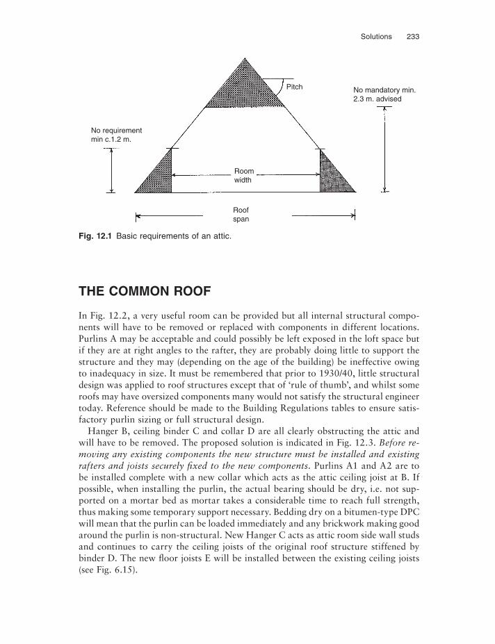
Solutions 233
THE COMMON ROOF
In Fig. 12.2, a very useful room can be provided but all internal structural compo-nents will have to be removed or replaced with components in different locations. Purlins A may be acceptable and could possibly be left exposed in the loft space but if they are at right angles to the rafter, they are probably doing little to support the structure and they may (depending on the age of the building) be ineffective owing to inadequacy in size. It must be remembered that prior to 1930/40, little structural design was applied to roof structures except that of ‘rule of thumb’, and whilst some roofs may have oversized components many would not satisfy the structural engineer today. Reference should be made to the Building Regulations tables to ensure satis-factory purlin sizing or full structural design.
Hanger B, ceiling binder C and collar D are all clearly obstructing the attic and will have to be removed. The proposed solution is indicated in Fig. 12.3. Before re-moving any existing components the new structure must be installed and existing rafters and joists securely fixed to the new components. Purlins A1 and A2 are to be installed complete with a new collar which acts as the attic ceiling joist at B. If possible, when installing the purlin, the actual bearing should be dry, i.e. not sup-ported on a mortar bed as mortar takes a considerable time to reach full strength, thus making some temporary support necessary. Bedding dry on a bitumen-type DPC will mean that the purlin can be loaded immediately and any brickwork making good around the purlin is non-structural. New Hanger C acts as attic room side wall studs and continues to carry the ceiling joists of the original roof structure stiffened by binder D. The new fl oor joists E will be installed between the existing ceiling joists (see Fig. 6.15).
Fig. 12.1 Basic requirements of an attic.
Pitch No mandatory min.2.3 m. advised
Roomwidth
Roofspan
No requirementmin c.1.2 m.
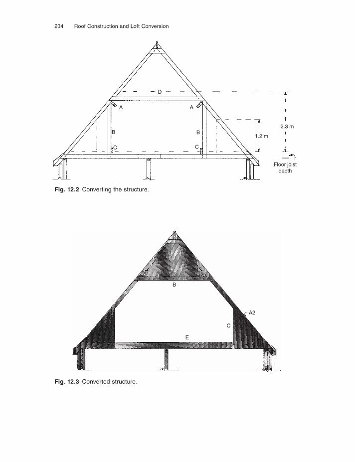
234 Roof Construction and Loft Conversion
Fig. 12.2 Converting the structure.
Fig. 12.3 Converted structure.
D
A
B
C
1.2 m
2.3 m
Floor joistdepth
C
B
A
B
C
E
A2
D
A1
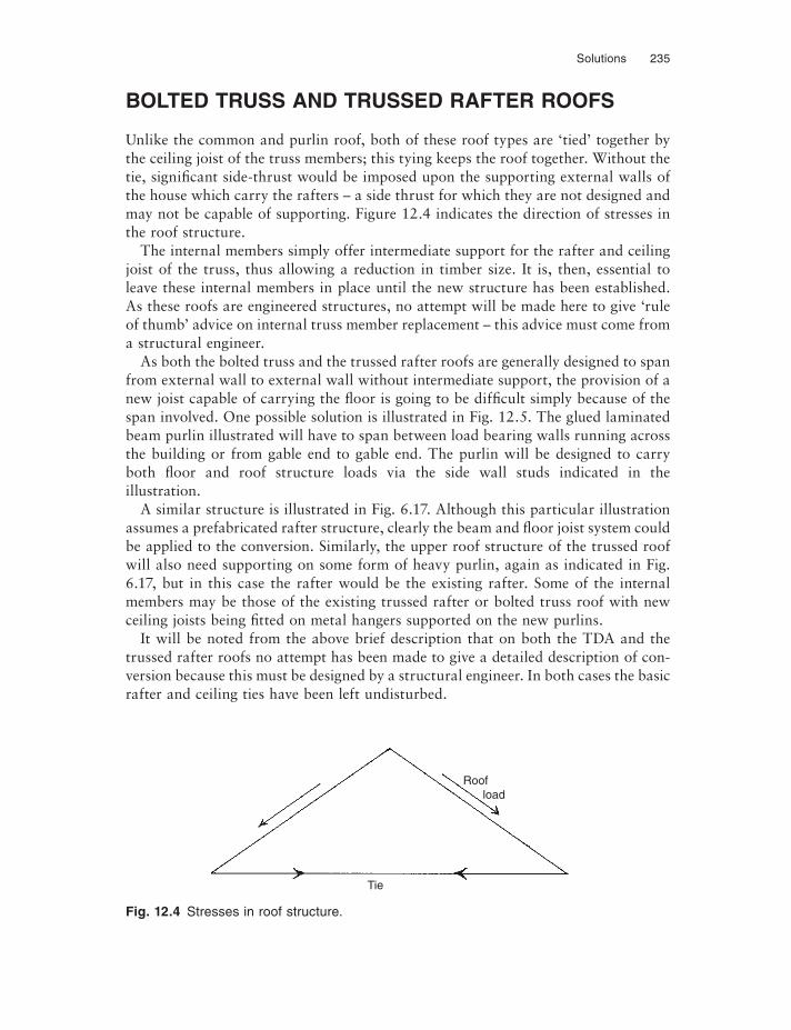
Solutions 235
BOLTED TRUSS AND TRUSSED RAFTER ROOFS
Unlike the common and purlin roof, both of these roof types are ‘tied’ together by the ceiling joist of the truss members; this tying keeps the roof together. Without the tie, significant side-thrust would be imposed upon the supporting external walls of the house which carry the rafters – a side thrust for which they are not designed and may not be capable of supporting. Figure 12.4 indicates the direction of stresses in the roof structure.
The internal members simply offer intermediate support for the rafter and ceiling joist of the truss, thus allowing a reduction in timber size. It is, then, essential to leave these internal members in place until the new structure has been established. As these roofs are engineered structures, no attempt will be made here to give ‘rule of thumb’ advice on internal truss member replacement – this advice must come from a structural engineer.
As both the bolted truss and the trussed rafter roofs are generally designed to span from external wall to external wall without intermediate support, the provision of a new joist capable of carrying the fl oor is going to be difficult simply because of the span involved. One possible solution is illustrated in Fig. 12.5. The glued laminated beam purlin illustrated will have to span between load bearing walls running across the building or from gable end to gable end. The purlin will be designed to carry both fl oor and roof structure loads via the side wall studs indicated in the illustration.
A similar structure is illustrated in Fig. 6.17. Although this particular illustration assumes a prefabricated rafter structure, clearly the beam and fl oor joist system could be applied to the conversion. Similarly, the upper roof structure of the trussed roof will also need supporting on some form of heavy purlin, again as indicated in Fig. 6.17, but in this case the rafter would be the existing rafter. Some of the internal members may be those of the existing trussed rafter or bolted truss roof with new ceiling joists being fi tted on metal hangers supported on the new purlins.
It will be noted from the above brief description that on both the TDA and the trussed rafter roofs no attempt has been made to give a detailed description of con-version because this must be designed by a structural engineer. In both cases the basic rafter and ceiling ties have been left undisturbed.
Fig. 12.4 Stresses in roof structure.
Roof load
Tie
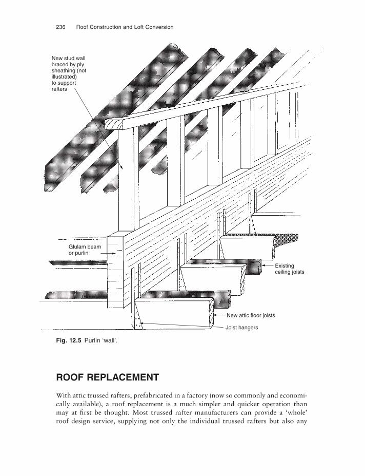
236 Roof Construction and Loft Conversion
Fig. 12.5 Purlin ‘wall’.
ROOF REPLACEMENT
With attic trussed rafters, prefabricated in a factory (now so commonly and economi-cally available), a roof replacement is a much simpler and quicker operation than may at fi rst be thought. Most trussed rafter manufacturers can provide a ‘whole’ roof design service, supplying not only the individual trussed rafters but also any
New stud wallbraced by plysheathing (notillustrated)to supportrafters
Glulam beamor purlin
Joist hangers
New attic floor joists
Existingceiling joists
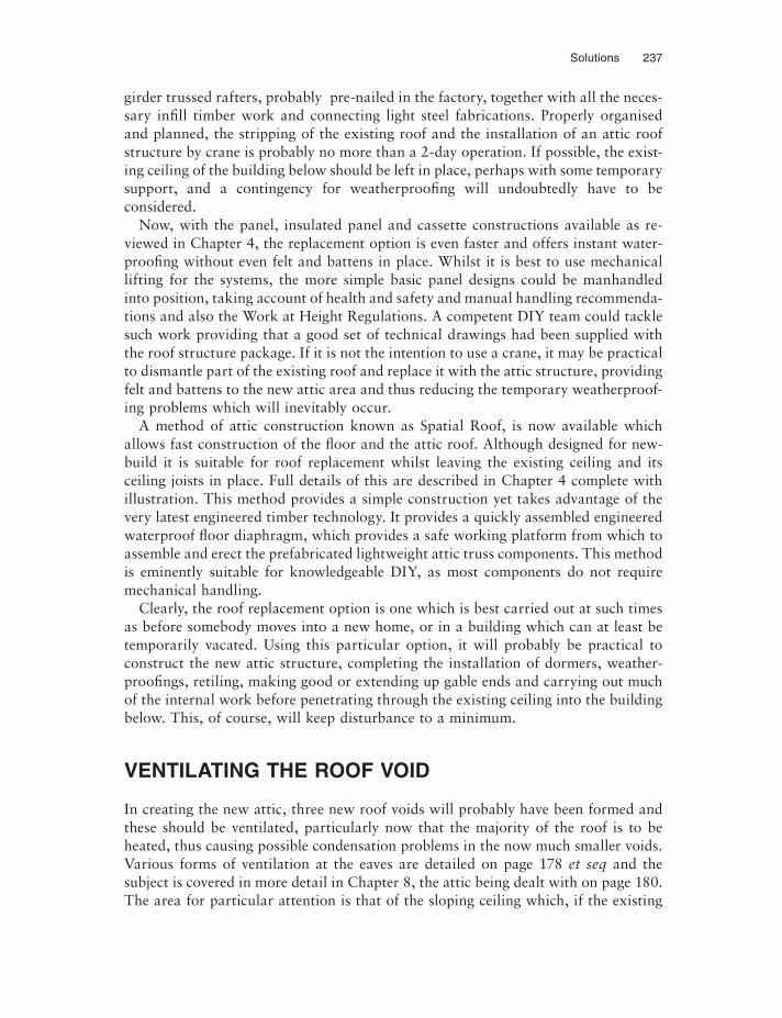
Solutions 237
girder trussed rafters, probably pre-nailed in the factory, together with all the neces-sary infi ll timber work and connecting light steel fabrications. Properly organised and planned, the stripping of the existing roof and the installation of an attic roof structure by crane is probably no more than a 2-day operation. If possible, the exist-ing ceiling of the building below should be left in place, perhaps with some temporary support, and a contingency for weatherproofi ng will undoubtedly have to be considered.
Now, with the panel, insulated panel and cassette constructions available as re-viewed in Chapter 4, the replacement option is even faster and offers instant water-proofing without even felt and battens in place. Whilst it is best to use mechanical lifting for the systems, the more simple basic panel designs could be manhandled into position, taking account of health and safety and manual handling recommenda-tions and also the Work at Height Regulations. A competent DIY team could tackle such work providing that a good set of technical drawings had been supplied with the roof structure package. If it is not the intention to use a crane, it may be practical to dismantle part of the existing roof and replace it with the attic structure, providing felt and battens to the new attic area and thus reducing the temporary weatherproof-ing problems which will inevitably occur.
A method of attic construction known as Spatial Roof, is now available which allows fast construction of the fl oor and the attic roof. Although designed for new-build it is suitable for roof replacement whilst leaving the existing ceiling and its ceiling joists in place. Full details of this are described in Chapter 4 complete with illustration. This method provides a simple construction yet takes advantage of the very latest engineered timber technology. It provides a quickly assembled engineered waterproof fl oor diaphragm, which provides a safe working platform from which to assemble and erect the prefabricated lightweight attic truss components. This method is eminently suitable for knowledgeable DIY, as most components do not require mechanical handling.
Clearly, the roof replacement option is one which is best carried out at such times as before somebody moves into a new home, or in a building which can at least be temporarily vacated. Using this particular option, it will probably be practical to construct the new attic structure, completing the installation of dormers, weather-proofi ngs, retiling, making good or extending up gable ends and carrying out much of the internal work before penetrating through the existing ceiling into the building below. This, of course, will keep disturbance to a minimum.
VENTILATING THE ROOF VOID
In creating the new attic, three new roof voids will probably have been formed and these should be ventilated, particularly now that the majority of the roof is to be heated, thus causing possible condensation problems in the now much smaller voids. Various forms of ventilation at the eaves are detailed on page 178 et seq and the subject is covered in more detail in Chapter 8, the attic being dealt with on page 180. The area for particular attention is that of the sloping ceiling which, if the existing
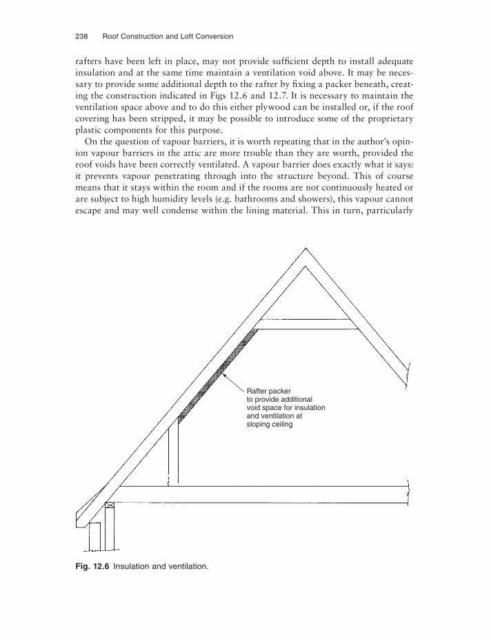
238 Roof Construction and Loft Conversion
rafters have been left in place, may not provide suffi cient depth to install adequate insulation and at the same time maintain a ventilation void above. It may be neces-sary to provide some additional depth to the rafter by fixing a packer beneath, creat-ing the construction indicated in Figs 12.6 and 12.7. It is necessary to maintain the ventilation space above and to do this either plywood can be installed or, if the roof covering has been stripped, it may be possible to introduce some of the proprietary plastic components for this purpose.
On the question of vapour barriers, it is worth repeating that in the author’s opin-ion vapour barriers in the attic are more trouble than they are worth, provided the roof voids have been correctly ventilated. A vapour barrier does exactly what it says: it prevents vapour penetrating through into the structure beyond. This of course means that it stays within the room and if the rooms are not continuously heated or are subject to high humidity levels (e.g. bathrooms and showers), this vapour cannot escape and may well condense within the lining material. This in turn, particularly
Fig. 12.6 Insulation and ventilation.
Rafter packerto provide additionalvoid space for insulationand ventilation atsloping ceiling
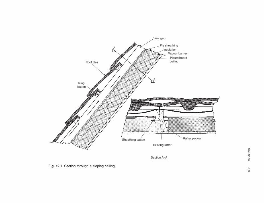
Solutions
239
Fig. 12.7 Section through a sloping ceiling.
Roof tiles
Tilingbatten
Vent gap
Ply sheathingInsulation
Vapour barrier
Plasterboardceiling
Sheathing batten
Existing rafter
Rafter packer
A
A
Section A–A
240 Roof Construction and Loft Conversion
in the areas of dead air circulation, can rapidly give rise to unsightly mould growth which is also difficult to eradicate once established. By dead areas of the room is meant those corners which are not subject to particularly good ventilation.
OPENINGS FOR DORMERS AND ROOF WINDOWS
Guidance on this is given in the final pages of Chapter 3 and in Chapters 5–8.
CONCLUSIONS
Chapters 10, 11 and 12 have attempted to give some guidance on roof structure conversion to living accommodation. The information is not exhaustive and does not cover all forms of roof structure or envisage all forms of intended use for the attic. It is not difficult to imagine a conversion for a snooker room with the installation of full-size slate bed snooker table, for instance, which would clearly introduce a whole new set of parameters for the loading of the new floor. Similarly, the installation of a grand piano, an exceptionally large bath or even the infamous water bed can be envisaged.
The imposed loads from a newly created private library in the attic would also be an unusual structural problem to solve. These chapters are intended to attract the attention of the DIY enthusiast or designer embarking on a proposed conversion, encouraging him to consider not just the conversion but its impact upon the occu-pants, the structure below and the architecture of the completed building. In the author’s opinion, the key to a successful conversion can be summed up as follows:
(1) Careful and detailed planning of the proposed conversion;(2) Careful counselling of the DIY enthusiast’s family or the architect’s client on the
impact upon them during the conversion and the benefi ts following the completion;
(3) Full appreciation of the impact upon the architecture of the building;(4) A fully detailed costing of the works before embarking on the project.
Bibliography, Standards and Technical References
STANDARDS AND TECHNICAL REFERENCES
TimberStructural Timber Composites – TRADA technology DG1: an introduction to composite
timber products including laminated veneer lumber, parallel strand lumber, and lami-nated strand lumber, includes example calculations to British and European standards.
Glued Laminated Timber – TRADA document WIS1-6: outlines structural forms and appli-cations possible with glulam.
BS 4978: 1996 Specification for visual strength grading of softwood.BS 5756: 1997 Specification for visual grading of hardwood.BS EN 336: 2003 Structural timber. Sizes, permitted deviations.BS EN 338: 2003 Structural timber. Strength classes.BS EN 518: 1995 Structural timber. Grading. Requirements for visual strength grading
standards.BS EN 519: 1995 Structural timber. Grading. Requirements for machine strength graded
timber and grading machines.
Timber Structure – TRADA publication VA4 1985: Shows the difference between hardwoods and softwoods.
Timber Drying – TRADA publication VA5 1985: Shows how wood loses moisture.
Moisture Content – TRADA publication VA6: Shows the importance of moisture content and how it is measured.
Structural designAn Introduction to Eurocode 5: Design of timber structures – TRADA publication GD1:
Outlines the European timber design code and its use.
BS EN 1995-1-1: 2004 Eurocode 5: Design of timber structures – Common rules and rules for buildings.
242 Bibliography, Standards and Technical References
BS EN 1995-1-2: 2004 Eurocode 5: Design of timber structures – General. Structural firedesign.
BS 5268-2: 2002: Structural use of timber – Code of practice for permissible stress design, materials and workmanship.
Multiple Fastener Joints: Guidance on BS5268-2 and Eurocode 5 – TRADA publication GD7: Explains the factors that affect strength and provides new design recommendations for BS5268-2 and DDENV1995-1.1 calculations.
Span Tables for Solid Timber Members for Floors, Ceilings and Roofs (Excluding Trussed Rafter Roofs) in Dwellings – TRADA publication DA1/2004: These tables are now re-ferred to by the Building Regulations. They cover C16 and C24 strength classes for timber fl oor joists, ceiling joists and binders, rafters and purlins for roofs between 15° and 45° and joists for flat roofs.
BS 8103-3: 1996: Structural design of low-rise buildings – Code of practice for timber floors and roofs for housing.
ConstructionBS 8201: 1997: Code of practice for flooring of timber, timber products and wood based
products.
Alpine Automation, Threemilestone, nr Truro, Cornwall, TR4 9LD, Telephone: 01872 245450, Fax: 01872 245451, Website: www.alpeng.co.uk Trussed Rafter Guide – recom-mendations for trussed rafter construction. Twin-I Beam Guide – recommendation for construction using twin-I beams.
American Plywood in Roof Construction: a Design Guide, available from BRE and APA – The Engineered Wood Association, publication CRCBR369 – Information to help users in specifying, selecting, designing and fabricating roof constructions using plywood.
Boise Building Products, Building 345 Heyford Park, Upper Heyford, Bicester, Oxfordshire, OX25 5HA, Telephone: 01869 238650, Fax: 01869 238660, Email: [email protected], Website: www.bc.com/uk – The simple framing system – A technical guide for fl oor and roof framing applications using I beams.
Excel Industries Ltd, Maerdy Industrial Estate, Rhymney, Tredegar, Gwent, NP22 5XS, Telephone: 01685 845200, Fax: 01685 844106, Email: sales@excelfi bre.com, Website: www.excelfi bre.com – Technical data on Tradis insulated panel structures.
Gang-Nail Systems Ltd, Christie Estate, Ivy Road, Aldershot, Hampshire, GU12 4XG, Telephone: 01252 334691, Fax: 01252 334562, Email: [email protected], Website: www.eleco.com/gangnail – Construction Manual for Trussed Rafter Roofs.
Kingspan Ltd, Greenfi eld Business Park Number 2, Greenfi eld, Hollywell, Flintshire, North Wales, CH8 7GJ, Telephone: 01352 716100, Fax: 01352 710161, Email: [email protected], Website: www.kingspanpanels.com – Insulated panels technical manual giving construction information on insulated structural support panels.
Milbank Roofs, Hargrove Meadow Cottage, Church Lane, Bury St Edmunds, Suffolk IP29 5HH, Telephone: 01284 852505, Fax: 01284 850021, Email: [email protected],
Bibliography, Standards and Technical References 243
Website: www.milbankroofs.com – Technical manual on the construction of Unilin systems panel roof construction.
MiTek Industries Ltd, MiTek House, Grazebrook Industrial Park, Peartree Lane, Dudley, West Midlands, D72 0XW, Telephone: 01384 451400, Fax: 01384 451415, Website: www.mitek.co.uk – The World of Roof Technology – Technical manual on the design and construction of trussed rafter roofs including pozi joist steel web system.
National House-Building Council Standards & Manual, available from NHBC, Buildmark House, Chiltern Avenue, Amersham, Bucks, HP6 5AP, Telephone: 0870 2414302, Fax: 01494 735201, Email: [email protected], Website: www.nhbc.co.uk
Roofing Ready Reckoner, 3rd edn, R. Goss (revised by C.N. Mindham), Blackwell Publishing, ISBN:0 632 05765 3 – Provides a quick reference for cut roof construction, giving tables for lengths of rafters, hips and valleys in metric and imperial for pitches between 5° and 75°. Can be used for attic construction.
Simpson Strong-Tie, Winchester Road, Cardinal Point, Tamworth, Staffordshire, B78 3HG, Telephone: 01827 255600, Fax: 01827 255616, Website: www.strongtie.co.uk – Connec-tors for Timber and Masonry Construction Document C-UK05 – Catalogue of metal connector plates and their structural performance.
smartroof Ltd, Old Station Road, Hampton in Arden, Solihull, West Midlands, B92 0HB, Telephone: 01675 442345, Fax: 01675 443095, Email: [email protected], Website: www.smartroof.co.uk – Technical manual on the construction of the smartroof® system.
TRADA Technology, Chiltern House, Stocking Lane, Howenden Valley, High Wycombe, Buckinghamshire, HP14 4ND, Telephone: 01494 569600, Fax: 01494 565487, Email: [email protected], Website: www.trada.co.uk – UK’s principle timber technology centre producing a wide range of technical, design and construction publications on all aspects of timber usage.
BM TRADA Certification Ltd, Stocking Lane, Hughendon Valley, High Wycombe, Bucks HP14 4ND, Telephone: 01494 569700, Fax: 01494 565487, Email: [email protected], website: www.bmtrada.com
Also at: The e-Centre, Cooperage Business Village, Alloa, Clackmannanshire, Scot-land, Telephone: 01259 272142, Fax: 01259 272144
Trus Joist, East Barn, Perry Mill Farm, Birmingham Road, Hopwood, Worcestershire, B48 7AJ, Telephone: 01214 456666, Fax: 01214 456677, Email: [email protected], Website: www.trusjoist.co.uk – Technical manual for silent fl oor and roof framing systems including I beams, timber strand, parallam and other proprietary products.
Trussed Rafter Association, PO Box 571, Chesterfi eld, S40 9DH, Telephone/Fax: 01246 230036, Email: [email protected], Website: www.tra.org.uk – Technical data sheets on the construction of trussed rafter roofs.
Velux Company Ltd, Woodside Way, Glenrothes East, Fife, Scotland, KY7 4ND, Telephone: 0870 4057700, Fax: 0870 4057701, Website: www.velux.co.uk – Design manual and product guide for Velux roof windows including detailed construction drawings and specification for the installation of roof windows in attic constructions.
Wolf Systems Ltd, Shilton Industrial Estate, Shilton, Coventry, Warwickshire, CV7 9QL, Telephone: 08707 339933, Fax: 08707 339944, Email: [email protected] Website: www.wolfsystem.co.uk – Trussed rafter technical manual, giving construction details for trussed rafter construction including easy-joist.
244 Bibliography, Standards and Technical References
PreservativesBS 1282: 1999 Wood preservatives guidance on choice, use and application.BS 8417: 2003 Preservation of timber recommendations.BS EN 335-1: 1992 Hazard classes of wood and wood-based products against biological
attack. Classification of hazard classes.BS EN 335-2: 1992 Hazard classes of wood and wood-based products against biological
attack. Guide to the application of hazard classes to solid wood.BS EN 335-3: 1996 Hazard classes of wood and wood-based products against biological
attack. Application to wood-based panels.BS EN 350-2: 1994 Durability of wood and wood based products. Natural durability of
solid wood. Guide to natural durability and treatability of selected wood species of importance in Europe.
Arch Timber Protection, Wheldon Road, Castleford, West Yorkshire, WFIO 2JT, Telephone: 01977 714000, Fax: 01977 714001, Email: [email protected], Website: www.archtp.com
Protim Solignum Ltd, Fieldhouse Lane, Marlow, Bucks, SL7 ILW, Telephone: 01628 486644, Fax: 01628 476757, Email: [email protected]
BOOKS
The Building Regulations Explained and Illustrated (12th edn) by M.J. Billington, M.W. Simons and J.R. Waters (2001) Blackwell Publishing, Oxford.
Loft Conversions by J. Coutts (2006) Blackwell Publishing, Oxford.
Roofing Ready Reckoner (3rd edn) by R. Goss, revised by C.N. Mindham (2001) Blackwell Publishing, Oxford.
Roofs and Roofing: Design and specification by D.T. Coates (1993) Whittles Publishing, Caithness, Scotland.
Timber Designers’ Manual (3rd edn) by E.C. Ozelton and J.A. Baird (2002) Blackwell Pub-lishing, Oxford.
Index
ashlars, 3assembly
bolted and connector roof, 71 et seqtrussed rafter roof, 82 et seq
asymmetric truss, 122attic conversion, 198 et seq
see also loft conversionattic floor, 52 et seq, 112attic roof bracing, 184–6attic roof development, 199attic roofs, 37 et seq, 52 et seqattic room height, 219, 233attic truss, 21, 122, 141
barge board, 23barn hip, 135battens – tiling, 120beamed ceiling, 202–205binders, 99bolted roof construction, 71 et seqbonnet hip, 133bottom chord, 86bracing – general, 180bracing – trussed rafters, 99, 119, 146
cantilever truss, 122cassettes – roof, 67ceiling, 6
joist, 23, 201–203collar, 2common rafter, 23computer programmes, 125cottage attic, 203coupled roof, 1cutting data trussed rafter, 129
diagonal brace, 86, 98, 101dormer, 23
attic, 46cheek, 23styles, 47
double ‘W’ truss, 20Dutch hip, 135
eaves, 24eaves details, 186eaves ventilation, 181Eurocodes, 16exposed beam floor, 201exposed rafters, 191, 193
fan truss, 19fascia, 23Fink truss, 19, 121
gable, 24gable hip, 133gable ladders, 166–9gable wall restraint, 173–5gablet, 23girder truss, 103glulam, 41, 53, 115
hammer beam, 6handling timber, 150health and safety, 62, 160hip
barn, 135Bolton truss, 77bonnet, 133Dutch, 135end, 23gable, 133rafter, 23roof, 32
Howe truss, 20
I-beams, 53insulated panel roofs, 65inverted Fink truss, 122
Jack rafter, 23
246 Index
King post, 5
lath and plaster ceiling, 201light
in lofts, 210roof windows, 215–17tubes, 214, 218
loft conversion, 198 et seqaccess to, 220bolted truss roof, 209decision making flow chart, 206–207hip and valley roof, 205lean to roof, 208, 212–13mono pitch roof, 208room height, 219, 233survey, 227terrace roof, 208trussed rafter roof, 209valleys, 219
metal nail plate beam, 55metalwork, 62mono pitch roof, 35mono pitch truss, 21, 122
nailed metal plate, 84Northlight truss, 122
openings in roof, 192–7OSB, 53
parapet wall, 170party wall, 171planning – loft conversion, 222ply box beam, 41ply web beam, 41ply wood gusset joint, 84Pratt truss, 20preservatives, 157principals, 3protective timber components, 152punched metal plates, 83 et seqpurlin, 7, 25, 28–31, 41, 145purlin wall, 236
quality control, 88 et seqQueen post, 6
rafter, 1, 145raised tie truss, 22, 122, 143, 146ridge, 23roof
bolted construction, 71 et seqcassettes, 67common rafter and purlin, 28 et seqconversions – attic, 204coupled, 1layout – trussed rafters, 126lights, 48panels, 65replacement – attic, 221, 236
shapes, 18–22stability, 80trussed rafter construction, 82 et seqwindow, 24, 48
sarking, 120scissor truss, 22soffi t, 24sous-laces, 3split ring connectors, 74sprockets, 193stair trimmers, 59storage of timber, 150strapping
gables, 175wall plates, 161–3
stress grades, 15
tie beam, 4toothed plate connectors, 71top chord, 86top hat truss, 122trimmers, 50, 59, 192–7, 216, 217truss clip, 165truss plate systems, 123 et seqtrussed purlin, 41trussed rafter roof construction, 82 et seq
attics, 109 et seqbuilding accuracy, 100construction sequence, 96–102cutting data, 129design, 85handling, 156hips, 103, 131manufacturing standards, 88 et seqmetalwork, 131raised tie, 141shapes, 121shoes, 108storage, 154trimming for openings, 109, 117typical roof layout, 126valleys, 103
trussed rafters, 11trusses, 7
TDA, TRADA, 9, 71 et seq
valley, 23structure, 36trussed rafters, 138
ventilation, 179–80, 237–9
wall plate, 23, 160 et seqwall plate strapping, 161–3water tank platforms, 174–8web, 86wind beam, 2windows
dormer, 23, 46, 47roof, 215–17