Embed Size (px)
Citation preview

Roof applications DGK, D9, D11, D12: Loads - Design
FRILO Software GmbH Page 3
Roof: Loads - Design
The present documentation provides additional information on our D9, D11, D12, and DGK roof applications.
Contents
Load assumptions as per EN 1991 4 Wind and snow loads 6 Superpositions as per EN 1990-1 7 Additional loads 7 Design settings 9 Buckling length (D9, D11, D12) 10 Calculation 11 Load transfer 15 Verification of the wind suction resistance 16 Further information and descriptions are available in the relevant documentations:
FDC – Basic Operating Instructions General instructions for the manipulation of the user interface
FDC – Menu items General description of the typical menu items of Frilo software applications
FDC – Output and printing Output and printing
FDC - Import and export Interfaces to other applications (ASCII, RTF, DXF …)
FCC Frilo.Control.Center - the easy-to-use administration module for projects and items
FDD Frilo.Document.Designer - document management based on PDF
Frilo.System.Next Installation, configuration, network, database
Roof applications DGK, D9, D11, D12: Loads - Design
Page 4 Software for structural calculation and design
Load assumptions as per EN 1991
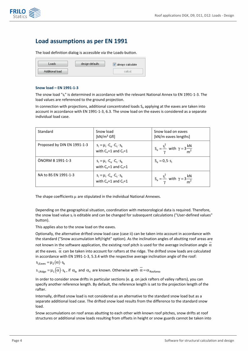
The load definition dialog is accessible via the Loads-button.
Snow load – EN 1991-1-3
The snow load "si" is determined in accordance with the relevant National Annex to EN 1991-1-3. The load values are referenced to the ground projection.
In connection with projections, additional concentrated loads Se applying at the eaves are taken into account in accordance with EN 1991-1-3, 6.3. The snow load on the eaves is considered as a separate individual load case.
Standard Snow load [kN/m² Gfl]
Snow load on eaves [kN/m eaves lengths]
Proposed by DIN EN 1991-1-3 i i e t ks C C s= m ◊ ◊ ◊ with Ce=1 and Ct=1
2i
es
S =g
with 2kN
3m
g =
ÖNORM B 1991-1-3 i i e t ks C C s= m ◊ ◊ ◊ with Ce=1 and Ct=1
e iS 0,5 s= ◊
NA to BS EN 1991-1-3 i i e t ks C C s= m ◊ ◊ ◊ with Ce=1 and Ct=1
2i
es
S =g
with 2kN
3m
g =
The shape coefficients are stipulated in the individual National Annexes.
Depending on the geographical situation, coordination with meteorological data is required. Therefore, the snow load value si is editable and can be changed for subsequent calculations ("User-defined values" button).
This applies also to the snow load on the eaves.
Optionally, the alternative drifted snow load case (case ii) can be taken into account in accordance with the standard ("Snow accumulation left/right" option). As the inclination angles of abutting roof areas are not known in the software application, the existing roof pitch is used for the average inclination angle a at the eaves. a can be taken into account for rafters at the ridge. The drifted snow loads are calculated in accordance with EN 1991-1-3, 5.3.4 with the respective average inclination angle of the roof:
( )i,Eaves 2 ks s= m a ◊
( )i,Ridge 1 ks s= m a ◊ , if lea and ria are known. Otherwise with Roofareaa =a
In order to consider snow drifts in particular sections (e. g. on jack rafters of valley rafters), you can specify another reference length. By default, the reference length is set to the projection length of the rafter.
Internally, drifted snow load is not considered as an alternative to the standard snow load but as a separate additional load case. The drifted snow load results from the difference to the standard snow load.
Snow accumulations on roof areas abutting to each other with known roof pitches, snow drifts at roof structures or additional snow loads resulting from offsets in height or snow guards cannot be taken into

Roof applications DGK, D9, D11, D12: Loads - Design
FRILO Software GmbH Page 5
consideration in the above-mentioned approaches to standard snow load. These particularities can be entered in the Additional loads section.
The National Annexes to EN 1991-1-3 allow the consideration of accidental snow loads for particular geographical areas. Since the factors for accidental snow loads vary in the different National Annexes and are intended as a recommendation, the Cesl value is editable in the software.
If another value is specified, the software application generates additional superpositions in accordance with the stipulations for accidental design situations and verifies these superpositions in addition. Only the decisive results are put out.
Regular snow load the snow load can be assigned to different action groups depending on the selected National Annex. When specifying an altitude in the wind and snow loads dialog, the action group is adjusted automatically in particular cases.
Activating the button displays the "Wind and snow loads" dialog, where you can define the ground snow load sk as well as the wind velocity pressure q in accordance with the respective wind zone and terrain category.
Wind load – EN1991-1-4
Wind pressure
The external wind pressure is determined in accordance with EN 1991-1-4, 5.2:
Wind pressure e pew c q= ◊ [kN/m² perpendicular to the roof surface]
The software application assumes that the load introduction area is larger than 10 m². Therefore, always the cpe,10 values are used as aerodynamic coefficients.
The cpe,10 values are determined for the flow direction 0 and the inner rafters in accordance with EN 1991-1-4, 7.2.3 to 7.2.5. This produces different wind loads for the G, H, J and I areas.
The G and J areas are assessed up to a distance of e/10 from the floor plan or the ridge. e is the smaller value of b (wind action width) or 2h (building height).
If alternative values are used, always the pressure coefficient is taken into account instead of the load-easing suction coefficient.
The aerodynamic coefficients as per 7.2.3 to 7.2.6 cannot be varied by selecting a different National Annex, whereas the other aerodynamic coefficients (e.g. for wind acting on walls) can. The values can be taken from the tables in the respective National Annex.
Wind uplift
For projections, the aerodynamic coefficient of the abutting wall is taken into account for wind uplift. For the windward side, the D-area coefficient and for the leeward side, the E-area coefficient is used.
On the top side, the wind pressure on the adjacent roof area is considered, i. e. the windward cantilever is entirely categorized as G area and the leeward cantilever as I area.
Man load P = 1 [kN] - EN 1991-1-1
Man loads applying in unfavourable points can be taken into account in the calculation of the internal forces in accordance with EN 1991-1-1, 6.3.4.
In the combination process, man load is treated as a separate action group (category H) and combined in accordance with the rules of EN 1990-1. A simultaneous inclusion of man load together with snow and wind load is not required according to EN 1991-1-1, 3.3.2(1).

Roof applications DGK, D9, D11, D12: Loads - Design
Page 6 Software for structural calculation and design
Wind and snow loads
Activating the button in the "Loads" dialog displays the "Wind and snow loads" dialog, where you can define impounding wind pressure or velocity pressure and regular or ground snow loads in accordance with the selected standard.
See also the document "Wind and snow loads".

Roof applications DGK, D9, D11, D12: Loads - Design
FRILO Software GmbH Page 7
Superpositions as per EN 1990-1
The combination rules for the semi-probalistic partial safety concept are laid down in EN 1990-1.
For the structural safety verification, the combinations for the permanent and transient design situations are generated. In addition, the accidental design situation (e. g. accidental snow load cases) can optionally be taken into account.
For the serviceability verification as per EN 1995-1-1, 7.2, only the infrequent and quasi-permanent design situations are relevant.
The software application generates internally all combinations in accordance with the specified rules and performs all corresponding verifications. Only the combinations that are decisive in the individual verifications are put out, however.
Additional loads
Click on the button to access the input dialog.
Additional loads can be defined for each rafter.
Type
111 Uniformly distributed load applying over the total length of the rafter, vertical load vectors referenced to the rafter axis.
112 Uniformly distributed load applying over the total length of the rafter, vertical load vectors referenced to the ground projection.
113 Uniformly distributed load applying over the total length of the rafter, load vectors pointing orthogonally to the rafter axis.
121 Single load with vertical load vector applying in the axis of the rafter.
122 Single load with horizontal load vector, applying in the axis of the rafter.
123 Single load with load vector perpendicular to the rafter axis.
128 Single load with load vector in direction of the rafter axis.
141 Trapezoidal load applying as a block to the rafter, vertical load vectors referenced to the rafter axis.
142 Trapezoidal load applying as a block to the rafter, vertical load vectors referenced to the ground projection.
143 Trapezoidal load applying as a block to the rafter, load vectors pointing orthogonally to the rafter axis.

Roof applications DGK, D9, D11, D12: Loads - Design
Page 8 Software for structural calculation and design
The cursor jumps to the relevant input columns in accordance with the defined load type.
Gle left load ordinate, permanent load portion
Gri right load ordinate, permanent load portion
(Dimension of line load: [kN/m rafter/1m wide] )
(Dimension of concentrated load: [kN/1m wide] )
Ple left load ordinate, variable load portion
Pri right load ordinate, variable load portion
Dist. distance of a concentrated or trapezoidal load from a previously defined measuring point (front edge of rafter), measured in the ground projection
Length projection length of a trapezoidal load, measured in the ground projection
Factor multiplication factor for the load ordinates
Act allows you to assign the variable load portion to an action group. For each load, an individual load case is generated and combined with the other load cases.
LAP load-action period
Alt alternative group, loads in an alternative group exclude each other. Example: wind loads from opposite directions.
Con concurrent group; loads that are assigned to the same concurrent group always act simultaneously.
These groups have priority over the alternative groups.
per B if this option is ticked, the load is processed as a beam-related load (e.g. q [kN/m]); if this option is unticked: the load is multiplied with the affected width e for processing (e. g. q [kN/m2]).
Dir this option allows you to consider the wind direction for wind loads.
D12: Valley rafters
The additional loads on valley rafters can be defined as normal additional loads. The following limitations apply to the load types, however:
Type
111 Uniformly distributed load applying over the total length of the rafter, vertical load vectors referenced to the rafter axis.
121 Single load with vertical load vector, applying in direction of the rafter axis.
141 Trapezoidal load applying as a block to the rafter, vertical load vectors referenced to the rafter axis.

Roof applications DGK, D9, D11, D12: Loads - Design
FRILO Software GmbH Page 9
Design settings
Click on the button to access the input dialog.
Deflection
Limitation of the span or cantilever deflection (referenced to the length L).
As the negative deflection of short cantilevers is decisive for the design result in most cases, you can eliminate this effect, if undesired, by checking the option "Positive deflection only".
Earthquake combinations
If this option is ticked, the combinations for earthquake loads are included in the output.
Gable projection
In the uplift resistance verification, this option allows you to take other suction loads into account via wind action on the gable.
Hot design
When activating this option, the stress resistance verifications are also performed for fire exposure.
In addition to the desired flame-resistance period tF, also the burning rate can be defined separately for each side.

Roof applications DGK, D9, D11, D12: Loads - Design
Page 10 Software for structural calculation and design
Buckling length (D9, D11, D12)
To define the effective length (buckling- / tilting) activate the corresponding item in the main tree.
The effective length and its border conditions in connection with buckling in plane and out of plane can be specified separately for each component.
The following conditions are optionally available:
- Continuously supported
- Effective length = member length
- Effective length = component length
- From eigenvalue calculation per load combination, optionally with an upper limit
- Same value for each member
- Different value for each member
Under fire exposure, the option referring to the eigenvalue calculation is not available because it would produce inconstant cross-sectional properties in the different verifications depending on the design method!

Roof applications DGK, D9, D11, D12: Loads - Design
FRILO Software GmbH Page 11
Calculation
Deflection
The value is defined in the "Design settings" menu. The negative deflection of short cantilevers is often decisive for the design result, In most cases, this effect is undesired and can be avoided by checking the option "Positive deflection only".
Always recalculate
You should only activate this option if the runtime behaviour of you computer is satisfactory, because calculation is repeated each time, you edit a defined value.
Interactive cross section design
The check values Eta Sigma and Eta f indicating the maximum utilization ratios for stress and deflection are displayed to allow the evaluation of the cross section.
In the current version, the stress resistance verification is performed for the maximum span loading and the maximum column loading.
The option "Always recalculate" must be active for the interactive cross section design. To change the cross section (b/d) of the rafter or ledger, proceed as follows:
- Position the cursor in the respective input field (b or d).
- Adjust the indicated values with the help of the arrow keys () of your keyboard.
- Check the values for Eta Sigma and/or Eta f
Attention: Large eaves projections may produce a situation where the cantilever is predominant in the design rather than the roof system. In this case, you should perform the design and/or the calculation of the bearing reactions separately.
Sign definition
The signs of the internal forces and the support reactions are defined in accordance with the conventions of the Frilo Framework application ESK.
The following conditions apply to internal forces:
- Axial forces N are positive as tension forces and negative as compression forces. - The signs of shear forces Q are determined in accordance with the acknowledged rules of civil
engineering. - Bending moments M are positive if they generate tension in the tension zone of the member
(dashed line parallel to the axis).
The supporting forces are put out as reaction forces.
- Horizontal support reactions are positive when they act in the negative direction of the x-axis. - Vertical support reactions are positive when they act from the bottom to the top. - Torques at the support are positive when the act anti-clockwise.
The support reactions are referenced to the global x-z system of coordinates.

Roof applications DGK, D9, D11, D12: Loads - Design
Page 12 Software for structural calculation and design
Load-bearing capacity verification as per EN 1995-1-1
The stresses are calculated for each load case in all eightpart points on each member from the locally applying internal forces. Only the decisive stresses are put out.
The stress resistance verifications are performed as specified by para. 6.2. For the shear stress resistance verification, the full shear force applying to the support is taken into account.
The stability verification is based on the equivalent bar method specified by para. 6.3.
The buckling length sK for the stability verification of the rafters is determined by default from the eigenvalue analysis for each load case.
Since at low normal forces stressed beams can produce huge buckling lengths, sK is limited to 0.9 times the length of the rafters.
The user also has the optional capability to change the border conditions, or to define the buckling lenght for every bar - see “Buckling- and tilting length”.
Serviceability verifications as per EN 1995-1-1
The serviceability verifications are based on the stipulations of the National Annexes to EN 1995-1-1, 7.2. and 2.2.3:
Standard Verifications Design situation
Proposed by EN 1995-1-1 wInst, wfin, wnet Characteristic situation
wQ,inst, wfin* Characteristic situation ÖNORM B 1995-1-1
wnet Quasi-permanent situation
DIN EN 1995-1-1/NA:2010 As specified by EN 1995-1-1
The deformations wQ,inst, wfin* in the characteristic design situation and wfin in the quasi-permanent design situation are calculated in accordance with ÖNORM B 1995-1-1:2009, 5.7.2. The limitation of vibrations in accordance with EN 1995-1-1, 7.3 is currently not taken into account.
Hot design as per EN 1995-1-2
Part 2 of EN 1995 deals with the hot design. The following burning rates are specified as recommended values in table 3.1:
Timber n [mm/min]
Softwood ( K 3kg
290m
r ≥ ) 0.8
Laminated timber 0.7
Hardwood ( K 3kg
450m
r < ) 0.7
Hardwood ( K 3kg
450m
r ≥ ) 0.55
The selected NA determines the calculation method to be used (accurate/simplified) and whether a method is allowed, mandatory or forbidden.
EN 1995-1-2. 4.2.2 determines the simplified method (reduced cross section). EN 1995-1-2, 4.2.3 describes the more accurate method (reduced cross section and reduced properties).

Roof applications DGK, D9, D11, D12: Loads - Design
FRILO Software GmbH Page 13
Simplified method
The burn-off loss results from the expression ( )ef 0 fd d d t= + The cross section is reduced by the burn-off loss and the cross sectional properties are determined for the reduced cross section: fi efb b n d= - ◊ fi efd d n d= - ◊
mod,fik 1,0=
More accurate method
First, the cross section is reduced by the burn-off loss and the cross sectional properties are determined for the reduced cross section:
fi f fb b n t b n d(t )= - ◊b◊ = - ◊ fi f fd d n t d n d(t )= - ◊b◊ = - ◊
The strengths values are calculated as follows: 0,2 fi 0,05d,fi mod,fi mod,fi
M,fi M,fi
X k XX k k
◊= ◊ = ◊
g g
Bending mod,fi
1 uk 1
225 A= - ◊
Compression in direction of the grain mod,fi
1 uk 1
125 A= - ◊
Tension in direction of the grain, modulus of elasticity and shear modulus mod,fi
1 uk 1
333 A= - ◊
Timber kfi
Solid wood 1.25
Laminated timber
1.15
With laminated timber, the dispersion is lower and the bell curve narrower. The distance between 5 % and 20 % is therefore smaller and kfi too.
Special case: shear design under fire exposure
For mainly shear-loaded components, scientific findings are not available yet.
Experiments by M. Peter revealed that a beam mainly under shear load, which should have a sufficient load-bearing capacity according to the results of the simplified method failed in the supports under shear load!
Therefore, shear resistance is not verified in the hot design.
Instead of the verification, the shear stress in the cold situation with the full cross section is merely compared to the shear stress in the hot situation with the ideal remaining cross section in accordance with the simplified method.
ÖNORM B 1995-1-2:2008-12
The standards prohibits the more accurate method. Only the simplified method with a reduced cross section as per 4.2.2 is allowed.
DIN EN 1995-1-2/NA:2010-12
The standard allows both methods (4.2.2 and 4.2.3), but explicitly recommends using the simplified method in accordance with 4.2.2.

Roof applications DGK, D9, D11, D12: Loads - Design
Page 14 Software for structural calculation and design
NA to BS 1995-1-2:2004
The use of the method specified in 4.2.2 is recommended.
CSN EN 1995-1-2/NA:2006
Both methods are allowed.
D12: virtual supports on a non-sway collar-beam roof
If a non-sway collar-beam roof was defined, horizontally fixed supports are automatically inserted at the collar beam connections. The calculation of the internal forces, support reactions and deformations refers exclusively to this structural strut-and-tie system. The support reactions generated at the virtual supports are treated as axial force in the collar beam in the subsequent design. The verification of the valley plate's stiffening effect is not performed!
Anti-tilting protection
Anti-tilting protection of the rafters by roof battens is permissible according to EN 1995-1-1:/NA:2010, NCI to 6.3.1, if the roof span is 15 m, the rafter spacing is 1.25 m and the ratio of the cross section's height and width h/b is 4.
Anti-tilting protection with board formwork is permissible if g/q is < 0.5, the roof span is 12.5 m and the rafter spacing is 1.25 m
The following conditions must be satisfied in addition
- Length of the roof 0.8, but roof span 25 m
- Board width 12 cm
- Board offset 2 · rafter spacing
- Joint width 1 m
- Nail fixing of board 2 nails per chord and board joint
Verification of the wind suction resistance
See the chapter Verification of the wind suction resistance.

Roof applications DGK, D9, D11, D12: Loads - Design
FRILO Software GmbH Page 15
Load transfer
After the calculation of the roof, the software applications DLT (Continuous Beam) or HO7 (timber beam) can be launched via the main menu to design the purlins (if these software applications are installed on the computer).
The roof application transfers the selected support reactions of the currently active support to the DLT application. First, the single-span girder is generated with the defined material and cross section. You must select the actual purlin length and the number of spans manually in DLT. The loads are automatically generated as multispan loads acting over the entire girder length.
The data are NOT returned by DLT!
Support no. number of the support/purlin that should be transferred to the Continuous Beam application.
Material selection of the purlin material
Purlin dimensions definition of the purlin's cross section (b=width, d= thickness)
Load cases setting options for the load case table. You can decide whether to specify the factors in the load table manually or have a particular combination set automatically by the software.
You can select whether the maximum horizontal or vertical forces or the corresponding minimum forces should be used.
Load case table (fac) all calculated load cases are displayed in the load case table together with the corresponding vertical and horizontal forces. In the column fac, you can specify the factor that should be transferred to the Continuous Beam application.

Roof applications DGK, D9, D11, D12: Loads - Design
Page 16 Software for structural calculation and design
Verification of the wind suction resistance
EN 1991-1-4:2010
The verification is always performed for the most unfavourable rafter in the edge area because the upwind loads in the F area are always greater than in the G or E area (in the middle).
In addition to the wind directions "from the left" and "from the right", also the flow direction towards the gable is taken into account.
In the uplift resistance verification always the cpe1 wind coefficients are used, because the uplift protections are always considered to act in particular points.
The combination process is performed as specified by EN 1990, A.1.3, table A.1.2.(A) in accordance with the stipulations on the position stability verification.
The output table specifies the design resistances in the x- and z- direction (horizontal and vertical) in addition to the required design resistance of the protections perpendicular to the rafter axis.