Embed Size (px)
Citation preview
Read these instructions carefully. These instructions MUST stay with this product.
USASERVICE OFFICEDometic Corporation1120 North Main StreetElkhart, IN 46514
CANADADometic Corporation46 Zatonski, Unit 3Brantford, ON N3T 5L8CANADA
SERVICE CENTER &DEALER LOCATIONSPlease Visit:www.eDometic.com
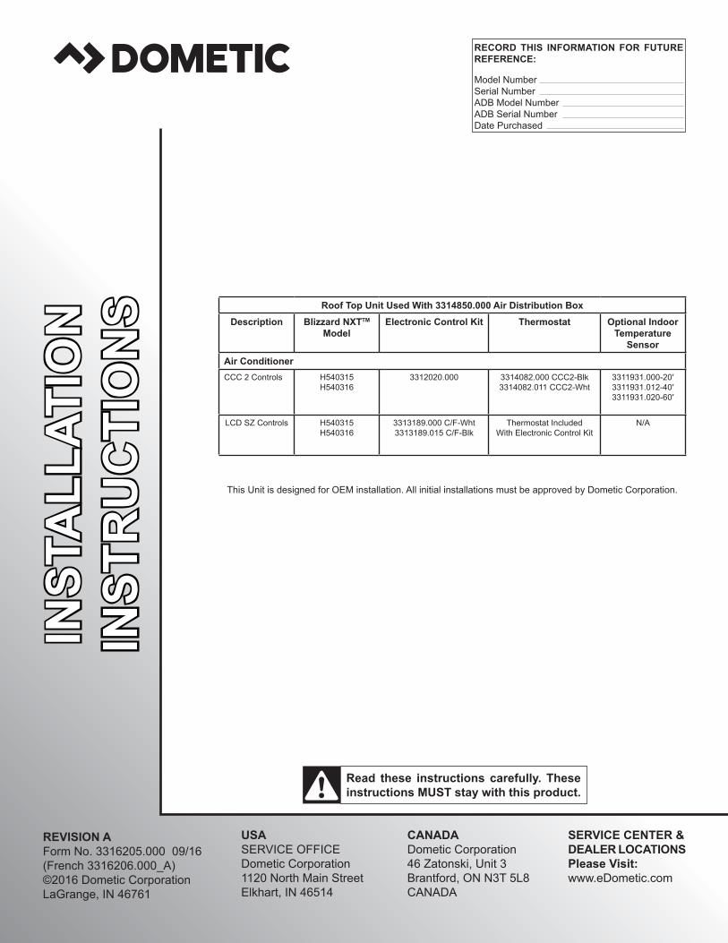
Roof Top Unit Used With 3314850.000 Air Distribution BoxDescription Blizzard NXTTM
ModelElectronic Control Kit Thermostat Optional Indoor
Temperature Sensor
Air ConditionerCCC 2 Controls H540315
H5403163312020.000 3314082.000 CCC2-Blk
3314082.011 CCC2-Wht 3311931.000-20′3311931.012-40′3311931.020-60′
LCD SZ Controls H540315H540316
3313189.000 C/F-Wht3313189.015 C/F-Blk
Thermostat IncludedWith Electronic Control Kit
N/A
This Unit is designed for OEM installation. All initial installations must be approved by Dometic Corporation.
RECORD THIS INFORMATION FOR FUTURE REFERENCE:
Model NumberSerial NumberADB Model NumberADB Serial NumberDate Purchased
REVISION AForm No. 3316205.000 09/16(French 3316206.000_A)©2016 Dometic CorporationLaGrange, IN 46761
INST
ALL
ATIO
NIN
STR
UC
TIO
NS

2
TABLE OF CONTENTSINTRODUCTION ....................................................................................................................................................................2DOCUMENT SYMBOLS ........................................................................................................................................................2IMPORTANT SAFETY INSTRUCTIONS ................................................................................................................................3
A. Recognize Safety Information ...................................................................................................................................3B. Understand Signal Words ..........................................................................................................................................3C. Supplemental Directives ............................................................................................................................................3D. General Safety Messages .........................................................................................................................................3
SPECIFICATIONS ..................................................................................................................................................................4A. Table - Unit Data ........................................................................................................................................................4B. Roof Requirements ....................................................................................................................................................4
INSTALLATION INSTRUCTIONS ..........................................................................................................................................4A. Choosing Proper Location For Unit ...........................................................................................................................4B. Roof Preparation .......................................................................................................................................................5C. Wiring Requirements .................................................................................................................................................5D. Choosing Thermostat Location ..................................................................................................................................6E. Thermostat, Optional Indoor Temperature Sensor & Thermostat Communication Cable Installation ......................6F. Placing Unit On Roof .................................................................................................................................................8G. Installation Preparation ..............................................................................................................................................8H. 120 Vac Power Supply Connection ...........................................................................................................................9I. Duct Divider Installation .............................................................................................................................................9J. LCD SZ System Low Voltage Wire Connections .....................................................................................................10K. CCC 2 System Low Voltage Wire Connections .......................................................................................................10L. (CCC2SystemOnly)Configuration ........................................................................................................................ 11M. Installing Unit ...........................................................................................................................................................12N. Installing ADB ..........................................................................................................................................................12O. (CCC 2 System Only) Reset & Checkout ................................................................................................................14P. (CCC 2 System Only) Furnace/Aqua Temperature Differential Setting ...................................................................14
GENERAL INFORMATION ...................................................................................................................................................15A. Heat Gain ................................................................................................................................................................15B. Condensation ..........................................................................................................................................................15
WIRING DIAGRAMS ............................................................................................................................................................16A. Simple RV Wiring Diagram ......................................................................................................................................16B. Unit Wiring Diagrams ...............................................................................................................................................17C. Electronic Control Kit Wiring Diagrams ...................................................................................................................17
DOCUMENT SYMBOLSIndicates additional information that is NOT related to physical injury.
Indicates step-by-step instructions.
INTRODUCTIONThis air conditioner (hereinafter referred to as “unit” or “product”) is designed and intended for installation on the roof of a Recreational Vehicle (hereinafter referred to as RV) during the time it is manufactured.Read these instructions and highlight the appropriate steps for your particular procedure before starting the installation.This unit can be installed by one person with brief help from additional personnel. Use these instructions to ensure a properly installed, and properly functioning product. DometicCorporationreservestherighttomodifyappearancesandspecificationswithoutnotice.

3
IMPORTANT SAFETY INSTRUCTIONSThis manual has safety information and instructions to help users eliminate or reduce the risk of accidents and injuries.
A. Recognize Safety InformationThis is the safety alert symbol. It is used to alert you to potential physical injury hazards. Obey all safety messages that follow this symbol to avoid possible injury or death.
B. Understand Signal WordsA signal word will identify safety messages and property damage messages, and will indicate the degree or level of hazard seriousness.
indicates a hazardous situation that, if NOT avoided, could result in death or serious in-jury.
indicates a hazardous situation that, if NOT avoided, could result in minor or moderate injury.
is used to address practices NOT related to physical injury.
C. Supplemental DirectivesRead and follow all safety information and instructions to avoid possible injury or death.
Read and understand these instructions be-fore [installing / using / servicing / performing maintenance on] this product.
Incorrect [installation / operation / servicing / maintaining] of this product can lead to seri-ous injury. Follow all instructions.
The installation MUST comply with all ap-plicable local or national codes, including the latest edition of the following standards:
U.S.A. ● ANSI/NFPA70, National Electrical Code
(NEC)
● ANSI/NFPA 1192, Recreational Vehicles Code
CANADA ● CSA C22.1, Parts l & ll, Canadian Electri-
cal Code
● CSA Z240 RV Series, Recreational Vehicles
D. General Safety Messages
Failure to obey the following warn-ings could result in death or serious injury:
● This product MUST be [installed / serviced] by a qualifiedservicetechnician.
● Do NOT modifythisproductinanyway.Modifica-tion can be extremely hazardous.
● Do NOT add any devices or accessories to this product except those specifically authorized inwriting by Dometic Corporation.

4
A. Table - Unit DataModel No. Nominal
Capacity(BTU HR)Cooling
ElectricalRating
CompressorRated Load
Amps
CompressorLocked RotorAmps
Fan MotorRated Load
Amps
Fan MotorLockedRotor Amps
RefrigerantR-410A
(oz)
MinimumWire Size*
AC CircuitProtection***InstallerSupplied
MinimumGenerator
Size**1 Unit / 2 Units
H540315.72X 13,500 120 Vac60 Hz 1 ph
12.7 68.0 2.8 8.0 19.5 12 AWGCopper
Up to 24'
20 Amp 3.5 kW / 5.0 kW
H540316.72X 15,000 13.2 70.0 2.8 8.0 20.1 20 Amp 3.5 kW / 5.0 kW
* For wire length over 24 ft., consult the National Electrical Code for proper sizing.** Dometic Corporation gives GENERAL guidelines for generator requirements. These guidelines come from experiences
people have had in actual applications. When sizing the generator, the total power usage of your RV must be considered. Keep in mind generators lose power at high altitudes and from lack of maintenance.
*** CIRCUIT PROTECTION: Time Delay Fuse or Circuit Breaker Required.
B. Roof Requirements ● A14-1/4″x14-1/4″(±1/8″)squareopening(hereinafterreferredtoas“roofopening”)isrequiredforinstallingthis
unit. This opening is part of the return air system of the unit and MUSTbefinishedinaccordancewithNFPA1192. ● Roof construction with rafters/joists support frames on a minimum of 16 inch centers. ● Minimum of 1-3/4 inches and maximum of 3-3/4 inches distance between roof to ceiling of RV.
SPECIFICATIONS
INSTALLATION INSTRUCTIONSA. Choosing Proper Location For UnitThisunitisspecificallydesignedforinstallationontheroofof an RV. When determining your cooling requirements, the following should be considered:
● Size of RV; ● Window area (increases heat gain); ● Amount of insulation in walls and roof; ● Geographical location where the RV will be
used; ● Personal comfort level required.
1. For one unit installation: The unit should be mounted slightly forward of center (front to back) and centered from side to side.
2. For two unit installations: Install one unit 1/3 and one unit 2/3’s from front of RV and centered from side to side.
Itispreferredthattheunitbeinstalledonarelativelyflatand level roof section measured with the RV parked on a level surface. See table below for maximum acceptable tilt.
ModelNumber
Max Tilt (All Directions)
H540315H540316
15°
3. After Location Has Been Selected:a. Check for obstructions in the area where unit
will be installed. See (FIG. 1).
FIG. 1 Dimensions Are Nominal
Keep These Air Flow Areas Free Of Obstructions
Front
Center Line Of UnitRoof Opening
13-7/8″
40″ 30″
4″
18″ 4″
b. Maintain structural integrity. Otherwise damage to product and/or RV could occur.The roof must be designed to support 130 pounds when RV is in motion. Normally a 200 lb. static load design will meet this requirement.
c. Check inside the RV for air distribution box (hereinafter referred to as "ADB") obstruc-tions (i.e. door openings, room dividers, cur-tains,ceilingfixtures,etc.).See(FIG.2).

5
FIG. 2
23-1/8″21-1/8″
2-5/8″
Dimensions Are Nominal
11-9/16″ 11-9/16″
21-1/8″
3-7/16″
3-7/16″
2-7/8″6″
Roof Opening
Faces Front
B. Roof Preparation
1. FIRE OR ELECTRICAL SHOCK HAZARD. Make sure there are no obstacles (wires, pipes, etc.) inside RV’s [roof / floor /walls]. Shut OFF gas supply, disconnect 120 Vac power from RV, and disconnect positive (+) 12 Vdc terminal from supply battery BEFORE drilling or cutting into RV. Failure to obey these warnings could result in death or serious injury.
Opening Requirements - Before preparing the ceiling opening, the type of system op-tions MUST be decided upon. Read all of the following instructions before beginning the installation.
2. Carefully mark and cut the required roof opening. See "B. Roof Requirements" on page (4).
3. Using the roof opening as a guide, cut the match-ing hole in the ceiling.
4. Maintain structural integrity. Oth-erwise damage to product and/or RV could oc-cur.
NEVER create a low spot on RV roof. Otherwise, water will pool and could cause a leak.
INSTALLATION INSTRUCTIONSThe opening created must be framed to provide adequate support and prevent air from being drawn from the roofcavity.Framingstock3/4″or more in thickness must be used. Remember to provide an entrance hole for power supplies, indoor temperature sensor (if applicable), ther-mostat communication cable, and furnace wires (if applicable) at the front of the opening. See (FIG. 3).
3/4″ Min.
Leave Access For Power Supply Wiring
FIG. 3
15″ Min. AtFront OfOpening
Do Not Cut RoofStructure OrRafters
Good-RaftersSupported By Cross Beams
Good LocationBetween Roof Rafters
Frame Opening So It Won't Collapse When Bolting Down Unit
C. Wiring Requirements1. Route a copper, with ground, 120 Vac supply
wire from the time delay fuse or circuit breaker box to the roof opening. Use a listed/certifiednon metallic - sheathed single strand cable. See "A. Table - Unit Data" on page (4).a. This supply wire must be located in the front
portion of the roof opening.b. The power MUST be on an appropriately
sized separate time delay fuse or circuit breaker. See "A. Table - Unit Data" on page (4).
c. Make sure that at least 15″ of supply wireextends into the roof opening. This ensures an easy connection at the junction box.
d. Protect the wire where it passes into the opening with approved method.
2. Route a dedicated 12 Vdc supply wire (18-22) AWG) from the RV converter (filtered side) orbattery to the roof opening.
6
INSTALLATION INSTRUCTIONSWhen a Comfort Control Center 2 (here-inafter referred to as CCC 2) thermostat is being installed with more than 2 zones, route a dedicated 12 Vdc supply wire (18-22 AWG) to zone 1 and zone 3 roof opening.
a. This supply wire must be located in the front portion of the roof opening.
b. Make sure that at least 15″ of supply wireextends into the roof opening.
3. Thermostat Communication Cablea. CCC 2 Thermostat
I. Route a 4 conductor communication ca-ble from the roof opening to the thermo-stat mounting location using the shortest most direct route. Make sure that at least 15″ofthewireextendsintotheroofopen-ing and 6″ extends from thewall at thethermostat mounting location. See "D. Choosing Thermostat Location" on page (6).
When more than one unit is being installed (additional zones) with the CCC 2 thermostat, an additional 4 conductor communication cable MUST be routed to each additional unit roof opening. Make sure that atleast15″ofthewireextendsintothe roof opening. See (FIG. 30).
b. LCD SZ ThermostatI. Route a 3 conductor communication ca-
ble, 18 to 22 AWG, from the roof open-ing to the Liquid Crystal Display Single Zone (hereinafter referred to a LCD SZ) thermostat mounting location. Make sure thatat least15″of thewireextends intotheroofopeningand6″extendsfromthewall at the thermostat mounting location. See "D. Choosing Thermostat Location" on page (6).
4. (CCC 2 system only) Optional Indoor Tempera-ture Sensora. Route an indoor temperature sensor (option-
al) from the roof opening to the indoor tem-perature sensor location. The 2 pin connec-tor end goes to the roof opening. See indoor temperature sensor installation instructions for proper sensor location.
5. If system includes a gas furnace, route two 18 gauge thermostat wires from the furnace to the roof opening of the unit that will control it. If more than one furnace is to be used, route the second set of thermostat wires to the second unit. Make sure that at least 15″ of wire extends into theopening.
6. (CCC 2 system only) If an Energy Management System (load shed feature) is to be used with the control, two wires must be routed to the roof opening of the zone to be managed. The signal required for this function is normally an open relay contact. When the (EMS) calls for the compressor to shut off, the relay contacts should close.Makesure thatat least15″of theEMSwire extends into the roof opening.
7. (CCC 2 system only) If an Automatic Generator Start (AGS) kit will be installed, an additional 4 conductor communication cable must be routed from the last unit to the location of the AGS kit. Follow AGS kit instructions for installation.
D. Choosing Thermostat Location1. CCC 2 system WITHOUT an optional indoor
temperature sensor and LCD SZ systema. The proper location of the thermostat is very
important to ensure that it will provide a com-fortable RV temperature. Observe the follow-ing rules when selecting a location.
● Locatethethermostat54″abovethefloor. ● Install the thermostat on a partition, not
on an outside wall. ● NEVER expose the thermostat to direct
heat from lamps, sun, or other heat pro-ducing items.
● Avoid locations close to doors that lead outside, windows, or adjoining outside walls.
● Avoid locations close to supply registers and the air from them.
2. CCC 2 system WITH an optional indoor temper-ature sensor in ALL zonesa. The thermostat may be mounted anywhere
in the RV that is convenient. Try to avoid hard to reach and hard to see areas.I. Refer to the instructions provided with the
indoor temperature sensor for details of installation.
E. Thermostat, Optional Indoor Temperature Sensor & Thermostat Communication Cable Installation 1. CCC 2 System
a. The previously run communication cable (4 conductor telephone cable) must be termi-nated with two (2) RJ-11-6C4P telephone connectors. Refer to the crimp tool manufac-turer for crimping instructions. See (FIG. 4) & (FIG. 5).
RJ-11-6C4P connectors MUST be in-stalled as shown in (FIG. 4) & (FIG. 5).

7
FIG. 4
FIG. 5
RJ-11-6C4P Connector
Pin 1B
lack
Red
Gre
enYe
llow
Bla
ckR
edG
reen
Yello
w
Flat Four Conductor Communication Cable
b. Route the communication cable through the 2" diameter hole in the wall required for the thermostat. See (FIG. 6).
FIG. 6CCC 2 Thermostat (Rear View)
Wall
2" Diameter
Communication Cable
c. Optional Indoor Temperature SensorI. Refer to the instructions provided with the
indoor temperature sensor for details of installation.
d. Thermostat InstallationI. Carefully separate the thermostat base
plate from the thermostat cover. Insert a small screw driver into the slot on bottom of thermostat and disengage the tab. See (FIG. 7).
FIG. 7
Disengage Tab
CCC 2 Thermostat
II. Insert the 4 conductor communication ca-ble through the hole in base plate. Align thermostat base plate with hole in wall. Make sure base plate is level and attach base plate to wall using the four (4) sup-plied screws.
III. Insert the 4 conductor communication cable connector (RJ-11-6C4P) into the connector on the back of the thermostat. See (FIG. 8).
FIG. 8
4 ConductorCommunication Cable
IV. Align the thermostat with the back plate and snap into position.
2. LCD SZ SystemWire colors listed for the communication cable (3 conductor cable) match the wire colors in the unit wire harness and the wire harness at the LCD SZ electronic control box. Available wire colors may vary.
INSTALLATION INSTRUCTIONS

8
a. Remove the cover from the LCD SZ thermo-stat. Depress tab on bottom of thermostat and separate it from the base.
b. Insert the previously run communication ca-ble (3 conductor cable) through the hole in the base assembly.
c. Cut back the outer cable shield approxi-mately3inchesandstrip1/4″insulationfromeach wire.
d. Mount the thermostat level on the wall using the screws provided.
e. Make the following connections to the ther-mostat. See (FIG. 9).
FIG. 9
12-
COMMS
12+
● Red/white wire to the 12V+ terminal ● Black wire to the 12V– terminal ● Orange wire to the "COMMS" terminal
f. Inspect all connections to make sure they are tight and not touching any other termi-nals or wires.
g. Push the wires back through the base into the wall. Place cover on the thermostat and push until an audible click is heard.
F. Placing Unit On Roof1. Remove the unit from the carton and discard
carton.2. LIFTING HAZARD. Use proper
lifting technique and control when lifting product. Failure to obey this caution could result in injury.Place unit on the roof.
3. Do NOT slide unit. Otherwise, damage to gasket (on bottom of unit) may occur, and could cause a leak.Lift and place the unit over the prepared open-ing using the gasket on the unit as a guide. See (FIG. 10).
FIG. 10
Do Not Slide
Lift And Place
Front
4. Place the electronic control box kit and the ADB kit inside the RV. These boxes contain mounting hardware for the unit and will be used inside the RV.
This completes the outside work. Minor adjustments can be done from inside the RV if required.
G. Installation Preparation1. Check gasket alignment of the unit over the
roof opening and adjust if necessary. Unit may be moved from below by slightly lifting. See (FIG. 11).
FIG. 11 Center Unit From Below
Roof Gasket
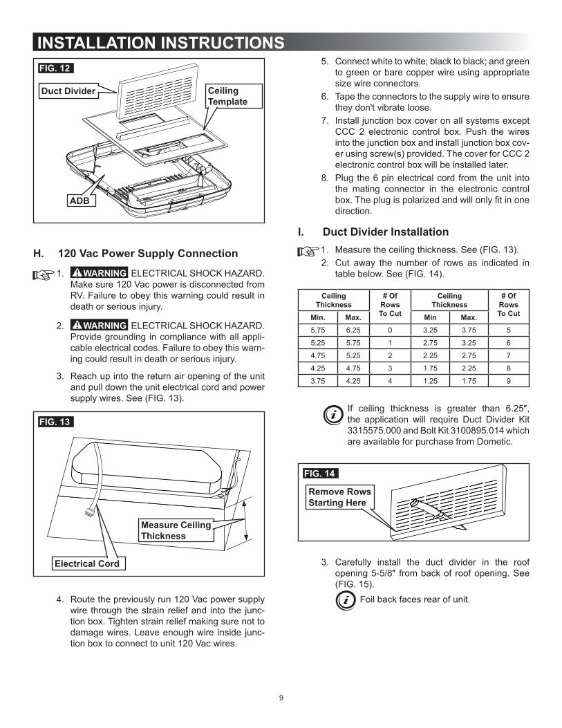
2. Remove ADB and mounting hardware from car-ton. See (FIG. 12).
3. All models in this manual will use a four (4) bolt pattern for installing the ADB kit.
INSTALLATION INSTRUCTIONS
9
5. Connect white to white; black to black; and green to green or bare copper wire using appropriate size wire connectors.
6. Tape the connectors to the supply wire to ensure they don't vibrate loose.
7. Install junction box cover on all systems except CCC 2 electronic control box. Push the wires into the junction box and install junction box cov-er using screw(s) provided. The cover for CCC 2 electronic control box will be installed later.
8. Plug the 6 pin electrical cord from the unit into the mating connector in the electronic control box.Theplugispolarizedandwillonlyfitinonedirection.
I. Duct Divider Installation1. Measure the ceiling thickness. See (FIG. 13).2. Cut away the number of rows as indicated in
table below. See (FIG. 14).
CeilingThickness
# Of RowsTo Cut
CeilingThickness
# Of RowsTo CutMin. Max. Min Max.
5.75 6.25 0 3.25 3.75 5
5.25 5.75 1 2.75 3.25 6
4.75 5.25 2 2.25 2.75 7
4.25 4.75 3 1.75 2.25 8
3.75 4.25 4 1.25 1.75 9
If ceiling thickness is greater than 6.25″,the application will require Duct Divider Kit 3315575.000 and Bolt Kit 3100895.014 which are available for purchase from Dometic.
FIG. 14
Remove Rows Starting Here
3. Carefully install the duct divider in the roof opening5-5/8″ frombackof roofopening.See(FIG. 15).
Foil back faces rear of unit.
FIG. 12
Duct Divider Ceiling Template
ADB
H. 120 Vac Power Supply Connection
1. ELECTRICAL SHOCK HAZARD. Make sure 120 Vac power is disconnected from RV. Failure to obey this warning could result in death or serious injury.
2. ELECTRICAL SHOCK HAZARD. Provide grounding in compliance with all appli-cable electrical codes. Failure to obey this warn-ing could result in death or serious injury.
3. Reach up into the return air opening of the unit and pull down the unit electrical cord and power supply wires. See (FIG. 13).
FIG. 13
Electrical Cord
Measure Ceiling Thickness
4. Route the previously run 120 Vac power supply wire through the strain relief and into the junc-tion box. Tighten strain relief making sure not to damage wires. Leave enough wire inside junc-tion box to connect to unit 120 Vac wires.
INSTALLATION INSTRUCTIONS

10
INSTALLATION INSTRUCTIONSFIG. 15
Rear
Base Pan
5-5/8″ From Back Of Roof Opening
Duct Divider Front
Black SideTo Front
J. LCD SZ System Low Voltage Wire Connections
Make sure the positive (+) 12 Vdc terminal is disconnected from supply battery. Oth-erwise, damage to unit could occur.
1. Plug the supplied freeze control sensor and the 4 wire harness into their matching connectors in the electronic control box.
2. Insert the freeze control sensor into the evapo-rator coil fins approximately 2-1/2″ above thebottomofthecoilfinsandin2-1/2″fromtherightside.See(FIG.16).Bendfinsoversensortose-cure in place.
FIG. 16
Route Up Through Return Air Opening
RemoveHang Tag
FreezeControl Sensor
3. Connect the previously run +12 Vdc supply wire to the red wire at the electronic control box.
4. Connect the previously run –12 Vdc supply wire to both the black wire at the electronic control box and to the wire of the three wire cable that goes to the thermostat 12V– terminal.
5. Connect the previously run furnace thermostat wires(ifapplicable)tothebluewirestothe1/4″connectors at the electronic control box using thesupplied1/4″insulatedconnectors.Thepo-larity of this connection does not mater.
6. Connect the red/white wire at the electronic con-trol box to the wire of the three wire cable that goes to the thermostat 12V+ terminal.
7. Connect the orange wire at the electronic control box to the wire of the three wire cable that goes to the thermostat COMMS terminal.
K. CCC 2 System Low Voltage Wire Connections
Make sure the positive (+) 12 Vdc terminal is disconnected from supply battery. Oth-erwise, damage to unit could occur.
1. Plug the freeze control sensor into the P5 (Blue or Black) 2 pin matching connector in the elec-tronic control box.
2. Insert the freeze control sensor into the evapo-rator coil fins approximately 2-1/2″ above thebottom of the coil fins and in 2-1/2″ from therightside.See(FIG.16).Bendfinsoversensorto secure in place.
3. Connect the previously run 12 Vdc supply wires to the red and black wires in the 6 wire harness at the electronic control box. Connect +12 Vdc to the red wire; –12 Vdc to the black wire.
4. Connect the previously run furnace thermostat wires (if applicable) to the blue wires protruding into the roof opening or the blue wires in the 6 wire harness at the electronic control box. The polarity of this connection does not matter.
5. Terminate the 4 conductor communication cable(s) protruding from the roof opening. The cable(s) must be terminated with a telephone RJ-11-6C4P connector. Refer to the crimp tool manufacturer for crimping instructions.
RJ-11-6C4P connectors MUST be in-stalled as shown in (FIG. 4) & (FIG. 5).
6. Plug the 4 conductor communication cable into the electronic control box. Use the second port to connect additional zone(s) (if applicable).
7. Plug the indoor temperature sensor cable (if ap-plicable) into the P4 (white) 2 pin matching con-nector in the electronic control box.
8. Connect the previously run Energy Manage-ment System wires (if applicable) to the 6 wire harness at the electronic control box. The polar-ity of this connection does not matter.
9. If an automatic generator start (AGS) kit is in-stalled, follow installation instructions furnished with AGS kit.

11
L. (CCC 2 System Only) Configuration1. ElectronicControlConfiguration
Depending on the equipment options installed by the RV manufacturer, the appropriate dip switches will need to be switched to the "ON" position. Placing the switch in the "ON" position selects that option. See (FIG. 17), (FIG. 18), & (FIG. 19).
Dip switches are in the "OFF" position when shipped from the factory except heat pump and factory installed heat strip models. On these models the appropriate dip switch, heat pump or heat strip, is in the "ON" position from the factory.
Switches are visible through the open-ing in the electronic control box. See (FIG. 17).
FIG. 17
Dip Switches
FIG. 18 Dip Switches
Zone 2Ext. Stage
Zone 3Zone 4StageHeat StripHeat PumpFurnaceDehumidifyGen Start
a. Ext. Stage - Ext. Stage is not used on this unit. Leave in the "OFF" position.
b. Zone selection - Each CCC 2 thermostat can have up to 4 zones. When only one unit is in-stalled it becomes Zone 1 and no dip switch setting is required. Each additional unit must be assigned a zone (2 through 4). Each unit must have a different zone setting.
c. Stage selection - Stage is not used on this unit. Leave in the "OFF" position.
d. Heat Strip - On heat strip models the #6 dip switch is in the "ON" position from the factory. Non heat strip models leave in the "OFF" position.
e. Heat Pump - On heat pump models the #7 dip switch is in the "ON" position from the factory. Non heat pump models leave in the "OFF" position.
f. Furnace - If a Furnace/Aqua heat system has been connected to this unit, the fur-nace dip switch must be placed in the "ON" position.
g. Dehumidify - Dehumidify is not used on this unit. Leave in the "OFF" position.
h. Gen Start selection - Leave in the "OFF" position.
i. Install unit electrical box cover and out side plastic shroud or the electronic control box cover whichever applies.
j. Repeat this procedure for each additional zone.
FIG. 19
On Position
Off Position
INSTALLATION INSTRUCTIONS

12
M. Installing Unit1. Install the electronic control box at this time.
Make sure all wiring has been completed and that the electronic control box cover has been installed. To secure electronic control box to ceiling templatedrive two(2)#6x3/8″(plasticcontrolbox)ortwo(2)#10x3/8″(metalcontrolbox) blunt point Phillips head screws (provided) through the ceiling template and into holes in the electronic control box. See (FIG. 20).
FIG. 20
Blunt Point Screw
Ceiling Template
Electronic Control Box
Metal Electronic Control Box Shown
2. If your installation includes the optional electric heat kit, install it at this time. Follow the instruc-tions with heat kit package for its installation pro-cedure.
3. Ceiling Template Installationa. Hold the ceiling template up to the roof open-
ing and line up the channel in the ceiling template with the previously installed duct divider. See (FIG. 21).
FIG. 21
Duct DividerChannel
b. Hold the ceiling template up to the roof open-ing and start each mounting bolt by hand, through the ceiling template and up into the unit base pan. See (FIG. 22) & (FIG. 23).
FIG. 22
Mounting Bolt
Mounting Bolt
Mounting Bolt Pattern Table See (FIG. 23)Model Bolt LocationH540315 A, D, E & HH540316 A, D, E & H
c. Tighten mounting bolts to correct torque specifications. Overtighten-ing could damage unit’s base pan or ceiling template. Not enough torque will allow an in-adequate roof seal, and could cause a leak.
d. Tighten all four (4) mounting bolts EVENLY within 40 to 50 inch pounds. See (FIG. 22).
FIG. 23 A
HGFE
DCB
N. Installing ADB1. Align ADB with ceiling template. See (FIG. 24)
& (FIG. 25).Front and rear vent doors are supplied loose. Do NOT install them until all screws are installed in step 2 & 3.
INSTALLATION INSTRUCTIONS

13
FIG. 24
ADB Alignment Holes
Ceiling Template Alignment Holes
FIG. 25
ADB Hole Alignment
Hole In Ceiling Template
Hole In ADB Cover
2. Install two (2) (supplied) sheet metal screws in-side return air opening to secure ADB to ceiling template. See (FIG. 25).
3. Install eight (8) (supplied) wood screws inside the front, rear, and side doors to secure ADB to ceiling. See (FIG. 26).
FIG. 26 2 SheetMetal Screws
8 Wood Screws
4. Install front and rear doors.5. Placefilter into returnairventgrille. Itmayal-
ready be installed on some units. See (FIG. 27).
FIG. 27Filter
Return Air Vent Grille
6. Install return air vent grille into the ADB. Slide re-turn air vent grille tab into slot in ADB and rotate up and snap in place. See (FIG. 28).
INSTALLATION INSTRUCTIONS

14
FIG. 28Slot In ADB
Return Air Vent Grille
This completes the LCD SZ system installa-tion. (Proceed to section "O" to complete the CCC 2 system installation).
7. (LCD SZ System Only) System Checkouta. Verify that all features of the system work.
See the LCD SZ thermostat Operating In-structions or User's Guide. Reconnect the 12 Vdc and 120 Vac power supplies. Check fan speeds, cooling mode, heating mode, and furnace mode (if connected) operation. If features do not work, disconnect the 120 Vac and 12 Vdc power supplies and verify that all wiring is correct.
O. (CCC 2 System Only) Reset & Checkout1. System Reset
After setting the dip switches in the electronic control, do a system reset.a. Re-connect the 12 Vdc and 120 Vac power
supplies.b. Make sure the CCC 2 thermostat is in the
OFF mode.c. Simultaneously press the MODE and ZONE
buttons. The LCD will display "IniT" and all available zones.
d. Release the MODE and ZONE buttons.e. Press the ON/OFF button to exit system set
up.f. When a dip switch is turned on after initial
configuration,asystemresetwillneedtobedone before the CCC 2 thermostat will rec-ognize the updated selection.
2. System Checkouta. Verify that all features of the installed sys-
tem work. See CCC 2 thermostat Operating Instructions or User's Guide. Check the fan mode, cooling mode, heating mode (if appli-cable), and furnace mode (if applicable) op-eration. If features do not work, disconnect the 120 Vac and 12 Vdc power supplies and verify that all wiring is correct and that the correct dip switches have been set to the "ON" position.
P. (CCC 2 System Only) Furnace/Aqua Temperature Differential SettingThissystemcanbeconfiguredtooperateusinganON//OFF differential of either 1 degree F or 2 de-gree F. See (FIG. 29).1. To set the differential, simultaneously press
the PROGRAM button and the up button on the CCC 2 thermostat. “diF1” will appear in the display while the buttons are pressed. See (FIG. 29). To set the 2 degree differential, simul-taneously press the PROGRAM button and the
down button “diF2” will appear in the display while the buttons are pressed.
FIG. 29
INSTALLATION INSTRUCTIONS

15
B. CondensationThe manufacturer of this unit will not be responsible for damage caused by condensation forming on ceilings, windows, or other surfaces. Air contains water vapor which condenses when temperature of a surface is below Dew point. During normal operation this unit is designed to remove a certain amount of moisture from the air, depend-ing on the size of the space being conditioned. Keeping doors and windows closed when this air conditioner is in operation will greatly reduce the chance of condensation forming on interior surfaces.
A. Heat GainThe ability of this air conditioner to maintain the desired inside temperature depends on the heat gain of the RV.
Some preventative measures taken by the occupants of the RV can reduce the heat gain and improve the perfor-mance of the air conditioner. During extremely high outdoor temperatures, the heat gain of the RV may be reduced by:
1. Parking the RV in a shaded area2. Using window shades (blinds and/or curtains)3. Keeping windows and doors shut or minimizing
usage4. Avoiding the use of heat producing appliances
Operation on High Fan/Cooling mode will give optimum ormaximumefficiency in highhumidity or highoutsidetemperatures.Starting the air conditioner early in the morning and giving it a “head start” on the expected high outdoor ambient will greatly improve its ability to maintain the desired indoor temperature.For a more permanent solution to high heat gain, acces-sories like Dometic outdoor patio and window awnings will reduce heat gain by removing the direct sun. They also add a nice area to enjoy company during the cool of the evening.
GENERAL INFORMATION

16
A. Simple RV Wiring Diagram
(OPTIONAL)
FIG. 30
WIRING DIAGRAMS
17
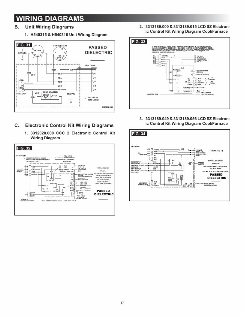
WIRING DIAGRAMSB. Unit Wiring Diagrams
1. H540315 & H540316 Unit Wiring Diagram
FIG. 31
C. Electronic Control Kit Wiring Diagrams1. 3312020.000 CCC 2 Electronic Control Kit
Wiring Diagram
FIG. 32
2. 3313189.000 & 3313189.015 LCD SZ Electron-ic Control Kit Wiring Diagram Cool/Furnace
FIG. 33
3. 3313189.049 & 3313189.056 LCD SZ Electron-ic Control Kit Wiring Diagram Cool/Furnace
FIG. 34