Embed Size (px)
Citation preview
Root Raised Cosine (RRC) Filters and Pulse Shaping in Communication Systems
Erkin Cubukcu
Abstract
This presentation briefly discusses application of the Root Raised Cosine (RRC) pulse shaping in the
space telecommunication. Use of the RRC filtering (i.e., pulse shaping) is adopted in commercial
communications, such as cellular technology, and used extensively. However, its use in space
communication is still relatively new. This will possibly change as the crowding of the frequency
spectrum used in the space communication becomes a problem. The two conflicting requirements in
telecommunication are the demand for high data rates per channel (or user) and need for more
channels, i.e., more users. Theoretically as the channel bandwidth is increased to provide higher data
rates the number of channels allocated in a fixed spectrum must be reduced. Tackling these two
conflicting requirements at the same time led to the development of the RRC filters. More channels with
wider bandwidth might be tightly packed in the frequency spectrum achieving the desired goals. A link
model with the RRC filters has been developed and simulated. Using 90% power Bandwidth (BW)
measurement definition showed that the RRC filtering might improve spectrum efficiency by more than
75%. Furthermore using the matching RRC filters both in the transmitter and receiver provides the
improved Bit Error Rate (BER) performance.
In this presentation the theory of three related concepts, namely pulse shaping, Inter Symbol
Interference (ISI), and Bandwidth (BW) will be touched upon. Additionally the concept of the RRC
filtering and some facts about the RRC filters will be presented.
Avio
nic
Sys
tem
s A
naly
sis
Root Raised Cosine Filters&
Pulse Shaping in Communication Systems
Erkin Cubukcu Friday, May 18, 2012

Avio
nic
Sys
tem
s A
naly
sis
25/7/2012
Outline
● Pulse Shaping, Intersymbol Interference (ISI), and Bandwidth
● Ideal Low Pass Filter (LPF)● Raised Cosine (RC)● Root Raised Cosine (RRC)● Facts about RRC● Link Modeling with the RRC Filters● Signal Spectra● BER Plots● Conclusions
Avio
nic
Sys
tem
s A
naly
sis
Pulse Shaping, Intersymbol Interference (ISI), and Bandwidth
35/7/2012
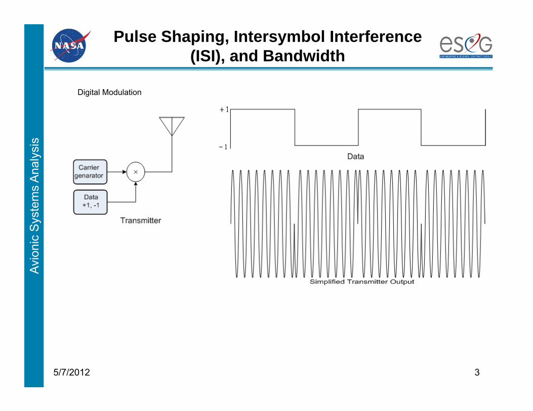
Digital Modulation
Avio
nic
Sys
tem
s A
naly
sis
Pulse Shaping, Intersymbol Interference (ISI), and Bandwidth (con’t)
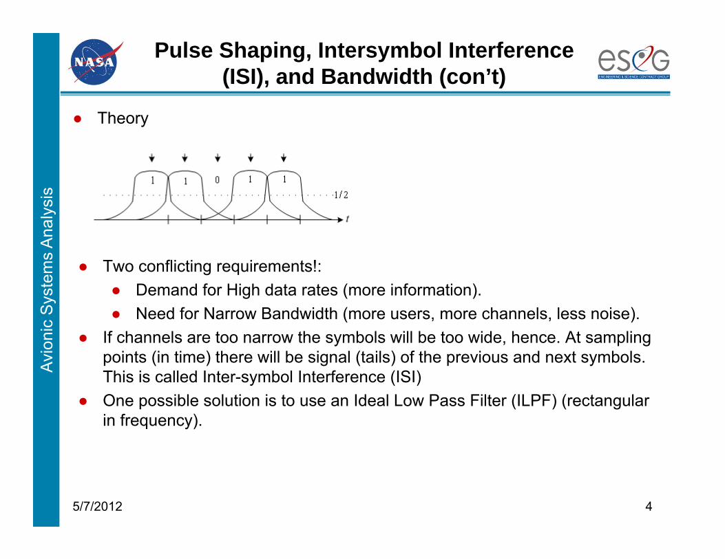
● Theory
45/7/2012
● Two conflicting requirements!:● Demand for High data rates (more information).● Need for Narrow Bandwidth (more users, more channels, less noise).
● If channels are too narrow the symbols will be too wide, hence. At sampling points (in time) there will be signal (tails) of the previous and next symbols. This is called Inter-symbol Interference (ISI)
● One possible solution is to use an Ideal Low Pass Filter (ILPF) (rectangular in frequency).
Avio
nic
Sys
tem
s A
naly
sis
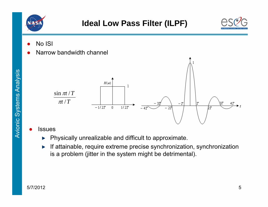
Ideal Low Pass Filter (ILPF)
● No ISI● Narrow bandwidth channel
55/7/2012
● IssuesPhysically unrealizable and difficult to approximate.If attainable, require extreme precise synchronization, synchronization is a problem (jitter in the system might be detrimental).
TtTt
//sin
Avio
nic
Sys
tem
s A
naly
sis
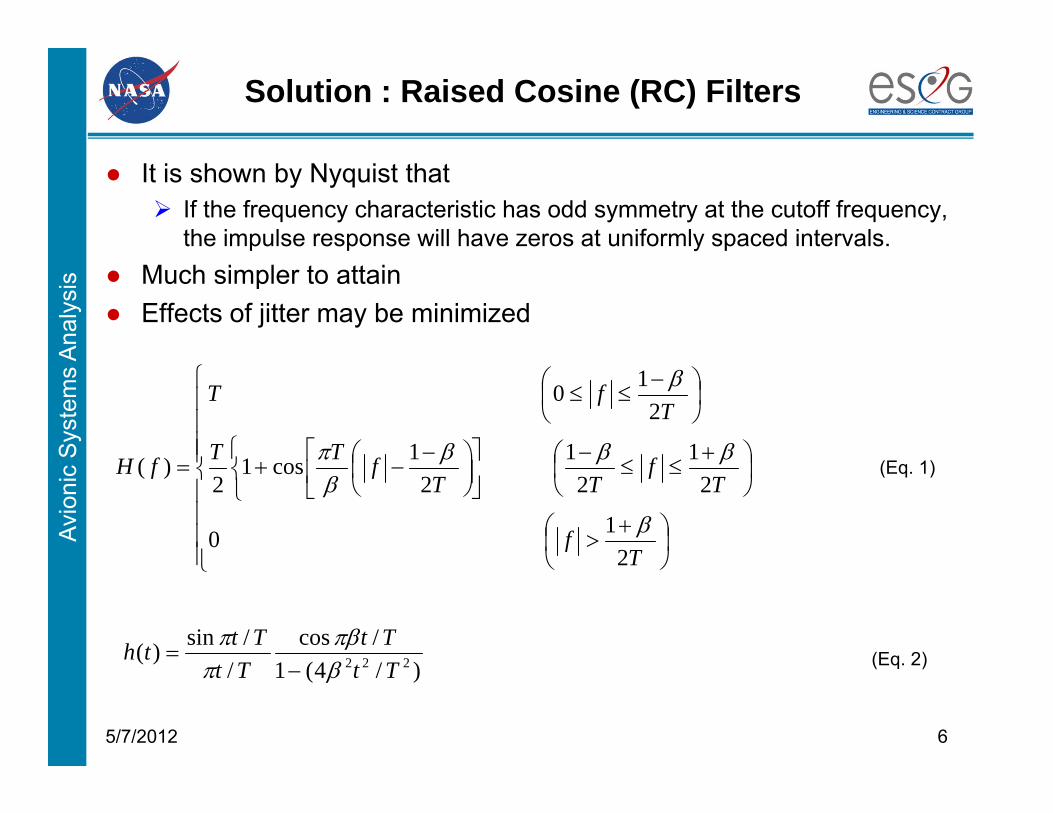
Solution : Raised Cosine (RC) Filters
● It is shown by Nyquist that If the frequency characteristic has odd symmetry at the cutoff frequency,
the impulse response will have zeros at uniformly spaced intervals.● Much simpler to attain● Effects of jitter may be minimized
65/7/2012
Tf
Tf
TTfTT
TfT
fH
210
21
21
21cos1
2
210
)(
)/4(1/cos
//sin)( 222 Tt
TtTt
Ttth
(Eq. 1)
(Eq. 2)
Avio
nic
Sys
tem
s A
naly
sis
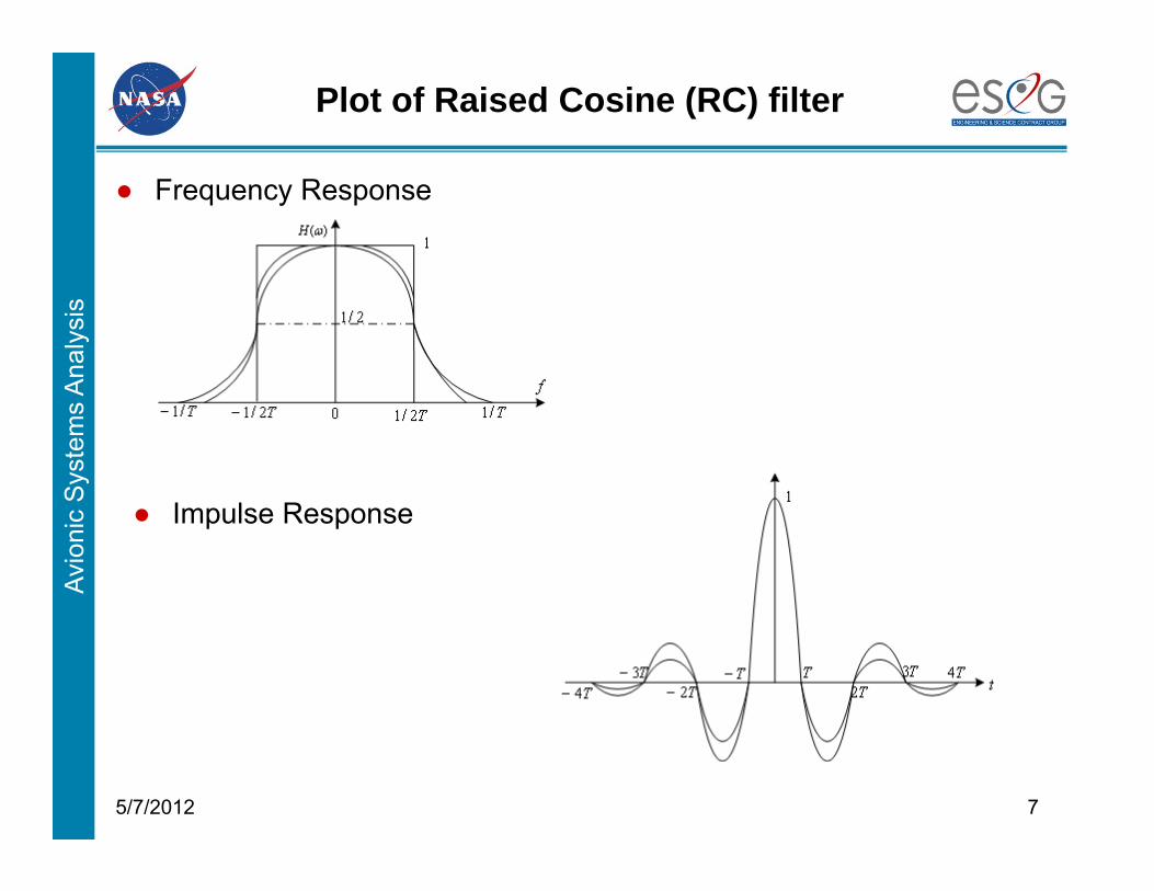
Plot of Raised Cosine (RC) filter
● Frequency Response
75/7/2012
● Impulse Response
Avio
nic
Sys
tem
s A
naly
sis
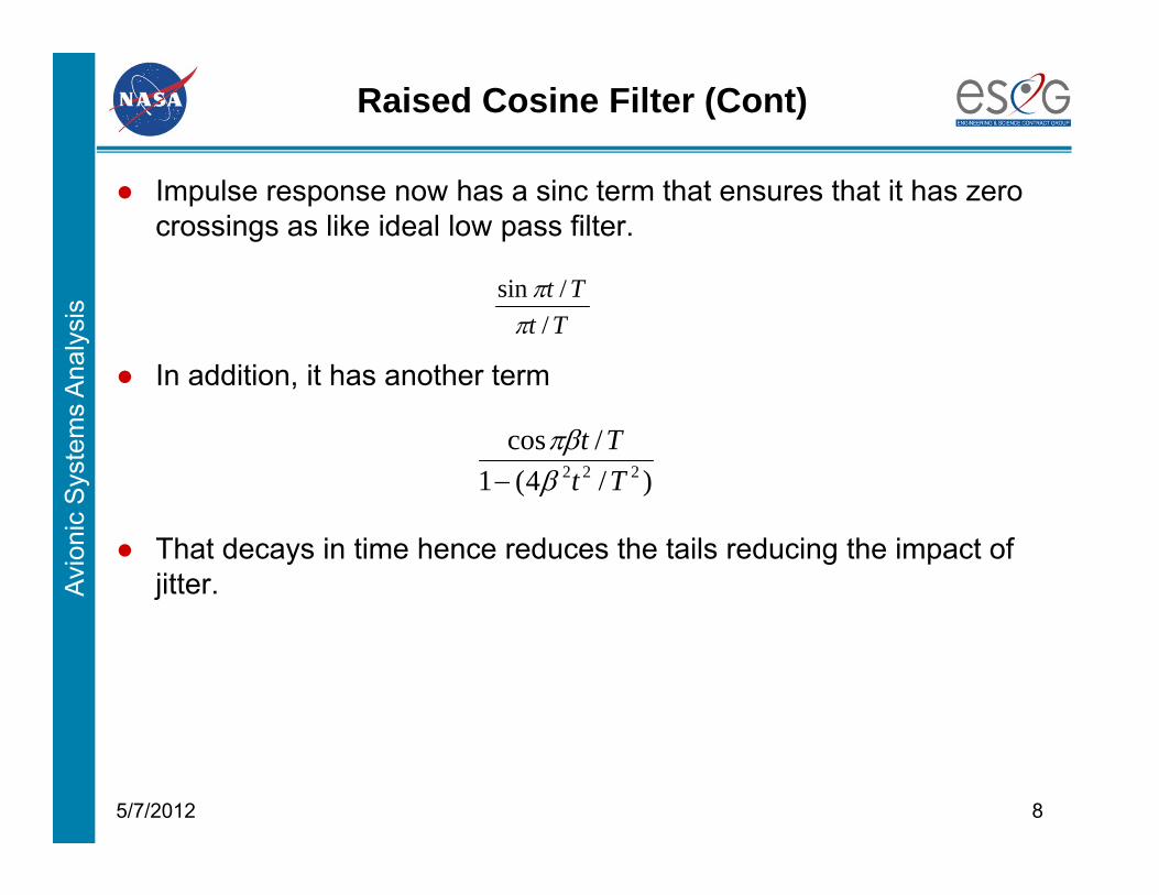
Raised Cosine Filter (Cont)
● Impulse response now has a sinc term that ensures that it has zero crossings as like ideal low pass filter.
85/7/2012
● In addition, it has another term
● That decays in time hence reduces the tails reducing the impact of jitter.
TtTt
//sin
)/4(1/cos
222 TtTt
Avio
nic
Sys
tem
s A
naly
sis
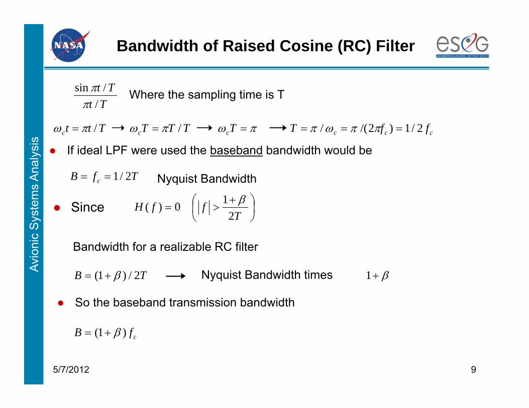
Bandwidth of Raised Cosine (RC) Filter
95/7/2012
Tttc /
● Since
TB 2/)1(
ccc ffT 2/1)2/(/
● So the baseband transmission bandwidth
● If ideal LPF were used the baseband bandwidth would be
TfB c 2/1 Nyquist Bandwidth
TtTt
//sin
Where the sampling time is T
TTTc / Tc
T
ffH2
10)(
Bandwidth for a realizable RC filter
cfB )1(
Nyquist Bandwidth times 1
Avio
nic
Sys
tem
s A
naly
sis
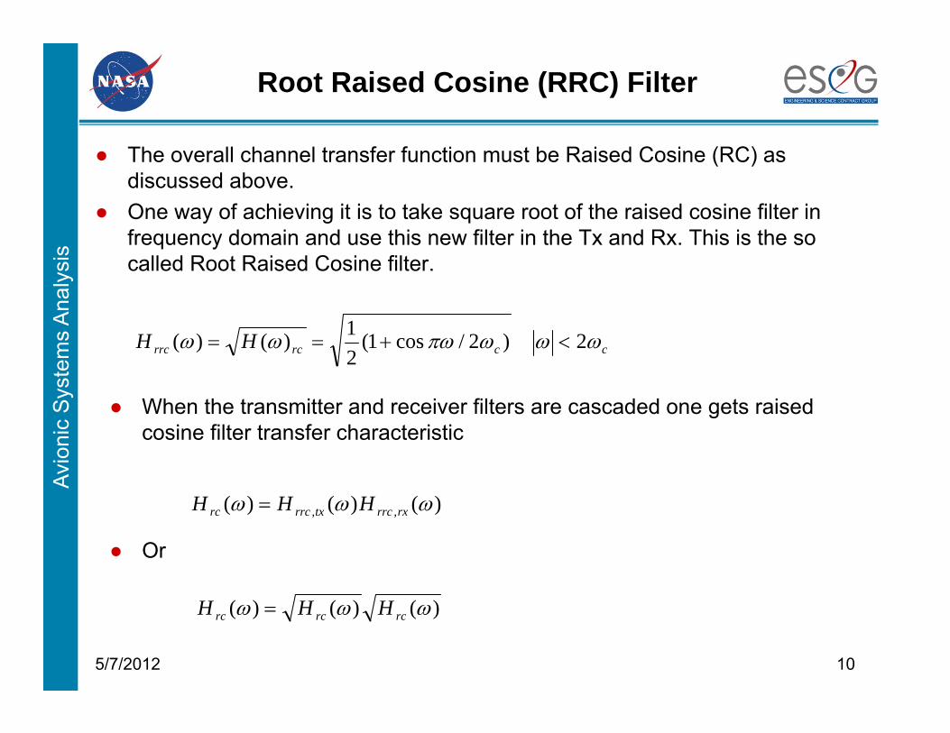
Root Raised Cosine (RRC) Filter
● The overall channel transfer function must be Raised Cosine (RC) as discussed above.
● One way of achieving it is to take square root of the raised cosine filter in frequency domain and use this new filter in the Tx and Rx. This is the so called Root Raised Cosine filter.
105/7/2012
ccrcrrc HH 2)2/cos1(21)()(
● When the transmitter and receiver filters are cascaded one gets raised cosine filter transfer characteristic
)()()( ,, rxrrctxrrcrc HHH
)()()( rcrcrc HHH
● Or

Avio
nic
Sys
tem
s A
naly
sis
Root Raised Cosine Filter (RRC) (con’t)
● By taking square root of RC filter frequency response, one gets.
115/7/2012
2)/4(1/4
]/)1sin[(]/)1cos[(2)(
TtTt
TtTt
Tth
Tf
Tf
TTfTT
TfT
fH
210
21
21
21cos1
2
210
)(
● Finding its impulse Response is a little bit tricky.
● Impulse response can also be generated numerically using IFFT.
Avio
nic
Sys
tem
s A
naly
sis
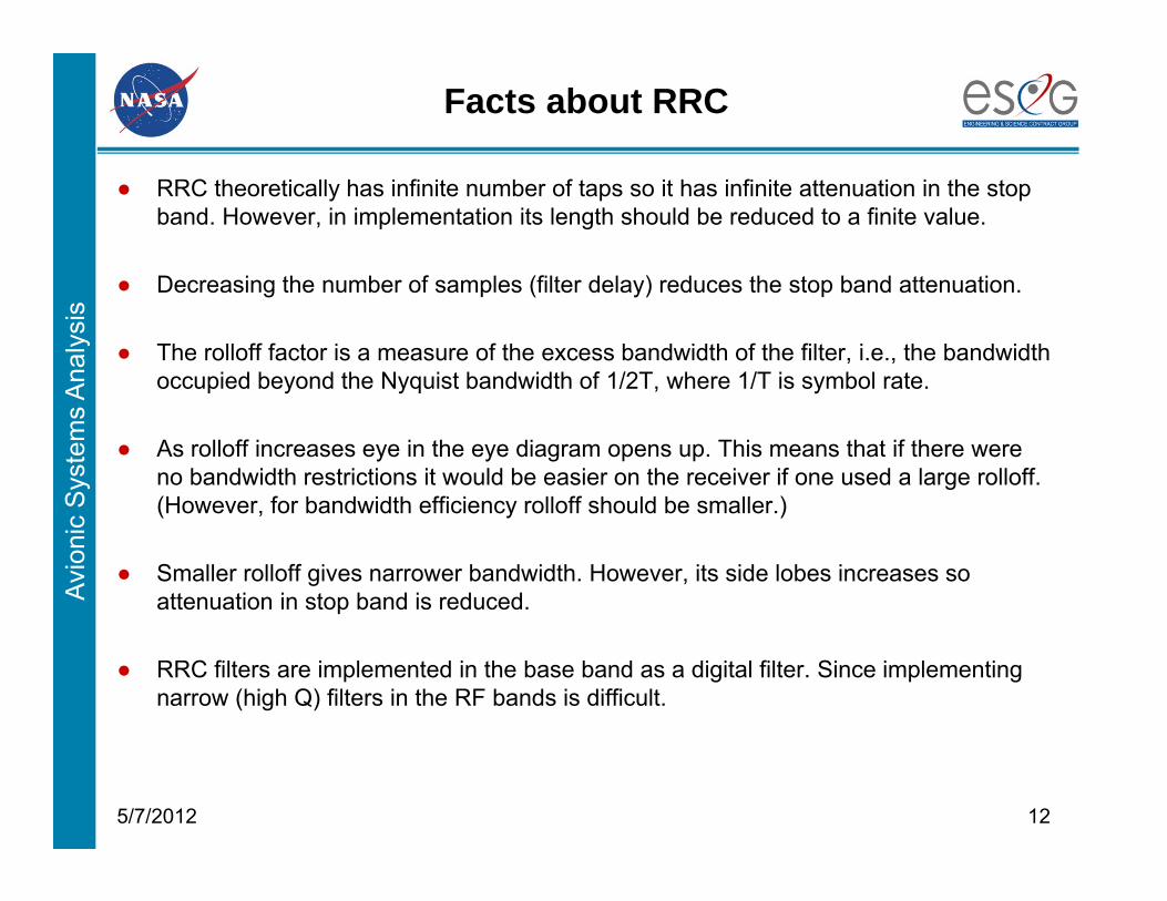
Facts about RRC
● RRC theoretically has infinite number of taps so it has infinite attenuation in the stop band. However, in implementation its length should be reduced to a finite value.
● Decreasing the number of samples (filter delay) reduces the stop band attenuation.
● The rolloff factor is a measure of the excess bandwidth of the filter, i.e., the bandwidth occupied beyond the Nyquist bandwidth of 1/2T, where 1/T is symbol rate.
● As rolloff increases eye in the eye diagram opens up. This means that if there were no bandwidth restrictions it would be easier on the receiver if one used a large rolloff. (However, for bandwidth efficiency rolloff should be smaller.)
● Smaller rolloff gives narrower bandwidth. However, its side lobes increases so attenuation in stop band is reduced.
● RRC filters are implemented in the base band as a digital filter. Since implementing narrow (high Q) filters in the RF bands is difficult.
125/7/2012
Avio
nic
Sys
tem
s A
naly
sis
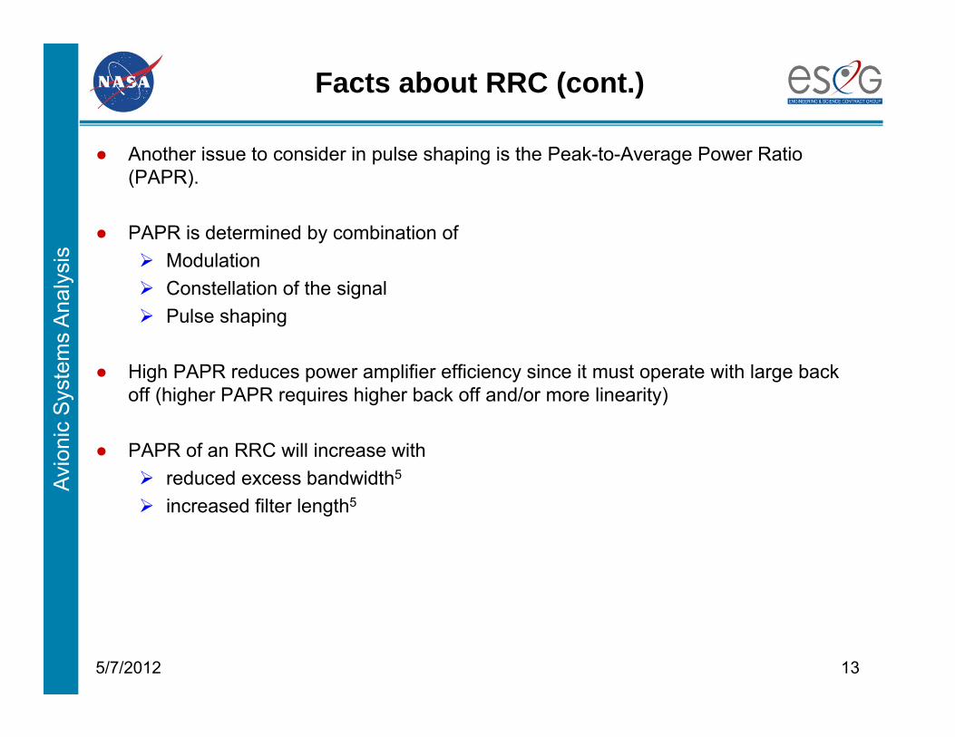
Facts about RRC (cont.)
● Another issue to consider in pulse shaping is the Peak-to-Average Power Ratio (PAPR).
● PAPR is determined by combination of Modulation Constellation of the signal Pulse shaping
● High PAPR reduces power amplifier efficiency since it must operate with large back off (higher PAPR requires higher back off and/or more linearity)
● PAPR of an RRC will increase with reduced excess bandwidth5
increased filter length5
135/7/2012
Avio
nic
Sys
tem
s A
naly
sis
Link Modeling with the RRC Filters
145/7/2012
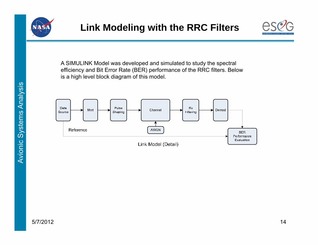
A SIMULINK Model was developed and simulated to study the spectral efficiency and Bit Error Rate (BER) performance of the RRC filters. Below is a high level block diagram of this model.

Avio
nic
Sys
tem
s A
naly
sis
Link Modeling with the RRC Filters (Cont.)Tx Model with RRC Pulse Shaping
155/7/2012
The modulator generates one symbol for each pair of data bits. The symbols generated by the modulator is up sampled and pulse shaped (filtered) to comply with the channel bandwidth restrictions. Typically, the pulse shaping is the last stage of transmitter before (DAC and) PA.
Avio
nic
Sys
tem
s A
naly
sis
Link Modeling with the RRC Filters (Cont.) Rx Model with RRC Filter
165/7/2012
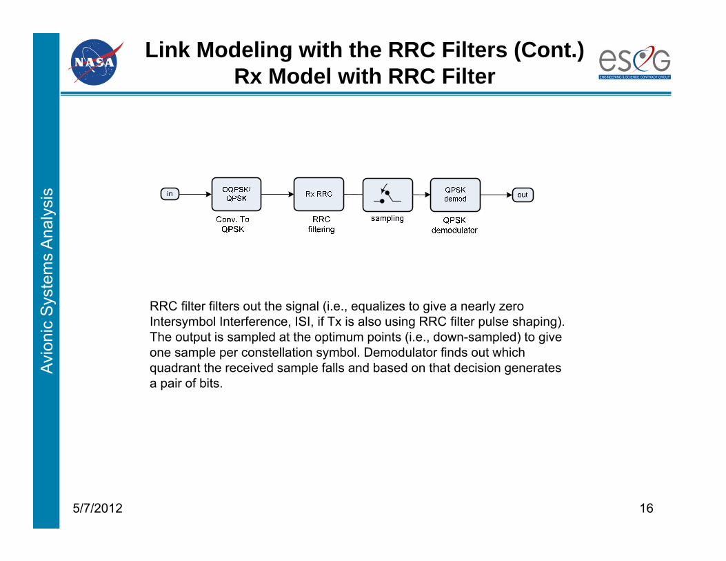
RRC filter filters out the signal (i.e., equalizes to give a nearly zero Intersymbol Interference, ISI, if Tx is also using RRC filter pulse shaping). The output is sampled at the optimum points (i.e., down-sampled) to give one sample per constellation symbol. Demodulator finds out which quadrant the received sample falls and based on that decision generates a pair of bits.
Avio
nic
Sys
tem
s A
naly
sis
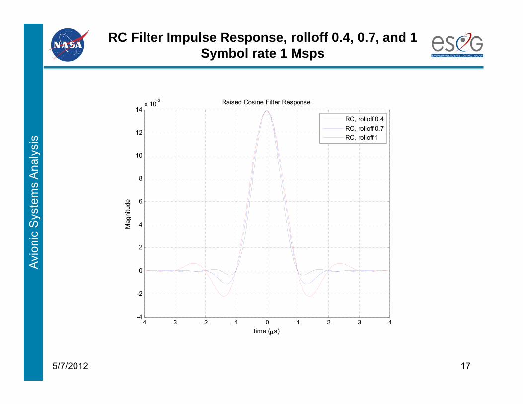
RC Filter Impulse Response, rolloff 0.4, 0.7, and 1Symbol rate 1 Msps
175/7/2012
-4 -3 -2 -1 0 1 2 3 4-4
-2
0
2
4
6
8
10
12
14x 10-3 Raised Cosine Filter Response
time (s)
Mag
nitu
de
RC, rolloff 0.4RC, rolloff 0.7RC, rolloff 1
Avio
nic
Sys
tem
s A
naly
sis
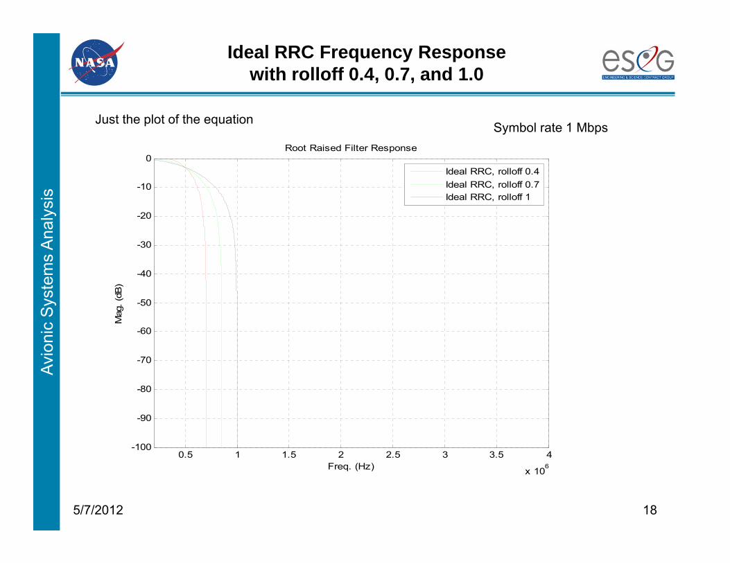
Ideal RRC Frequency Responsewith rolloff 0.4, 0.7, and 1.0
185/7/2012
Just the plot of the equation
0.5 1 1.5 2 2.5 3 3.5 4
x 106
-100
-90
-80
-70
-60
-50
-40
-30
-20
-10
0Root Raised Filter Response
Freq. (Hz)
Mag
. (dB
)
Ideal RRC, rolloff 0.4Ideal RRC, rolloff 0.7Ideal RRC, rolloff 1
Symbol rate 1 Mbps
Avio
nic
Sys
tem
s A
naly
sis
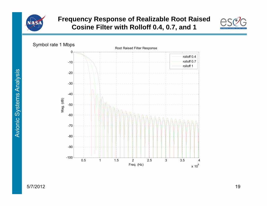
Frequency Response of Realizable Root Raised Cosine Filter with Rolloff 0.4, 0.7, and 1
195/7/2012
0.5 1 1.5 2 2.5 3 3.5 4
x 106
-100
-90
-80
-70
-60
-50
-40
-30
-20
-10
0Root Raised Filter Response
Freq. (Hz)
Mag
. (dB
)
rolloff 0.4rolloff 0.7rolloff 1
Symbol rate 1 Mbps
Avio
nic
Sys
tem
s A
naly
sis
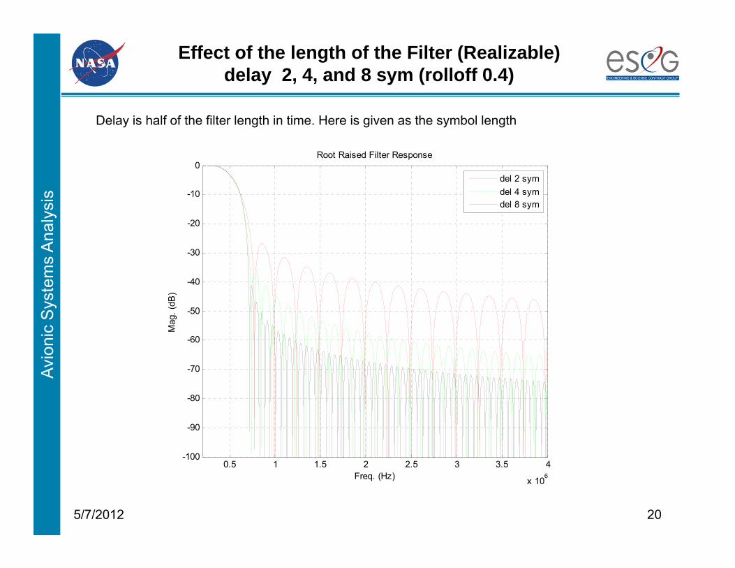
Effect of the length of the Filter (Realizable)delay 2, 4, and 8 sym (rolloff 0.4)
205/7/2012
0.5 1 1.5 2 2.5 3 3.5 4
x 106
-100
-90
-80
-70
-60
-50
-40
-30
-20
-10
0Root Raised Filter Response
Freq. (Hz)
Mag
. (dB
)
del 2 symdel 4 symdel 8 sym
Delay is half of the filter length in time. Here is given as the symbol length
Avio
nic
Sys
tem
s A
naly
sis
215/7/2012
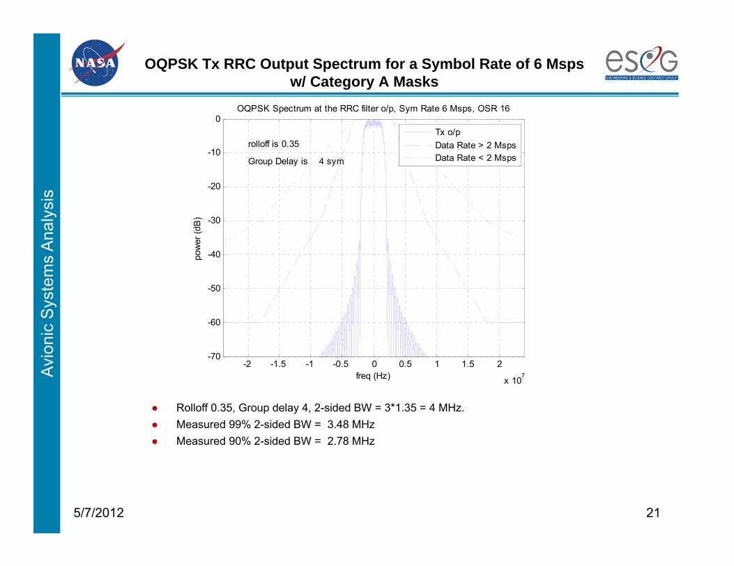
OQPSK Tx RRC Output Spectrum for a Symbol Rate of 6 Msps w/ Category A Masks
● Rolloff 0.35, Group delay 4, 2-sided BW = 3*1.35 = 4 MHz.
-2 -1.5 -1 -0.5 0 0.5 1 1.5 2
x 107
-70
-60
-50
-40
-30
-20
-10
0OQPSK Spectrum at the RRC filter o/p, Sym Rate 6 Msps, OSR 16
freq (Hz)
pow
er (d
B)
rolloff is 0.35
Group Delay is 4 sym
Tx o/pData Rate > 2 MspsData Rate < 2 Msps
● Measured 90% 2-sided BW = 2.78 MHz● Measured 99% 2-sided BW = 3.48 MHz
Avio
nic
Sys
tem
s A
naly
sis
225/7/2012
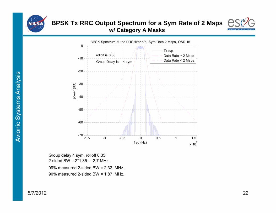
BPSK Tx RRC Output Spectrum for a Sym Rate of 2 Msps w/ Category A Masks
Group delay 4 sym, rolloff 0.35
-1.5 -1 -0.5 0 0.5 1 1.5
x 107
-70
-60
-50
-40
-30
-20
-10
0BPSK Spectrum at the RRC filter o/p, Sym Rate 2 Msps, OSR 16
freq (Hz)
pow
er (d
B)
rolloff is 0.35
Group Delay is 4 sym
Tx o/pData Rate > 2 MspsData Rate < 2 Msps
2-sided BW = 2*1.35 = 2.7 MHz.
99% measured 2-sided BW = 2.32 MHz.90% measured 2-sided BW = 1.87 MHz.
Avio
nic
Sys
tem
s A
naly
sis
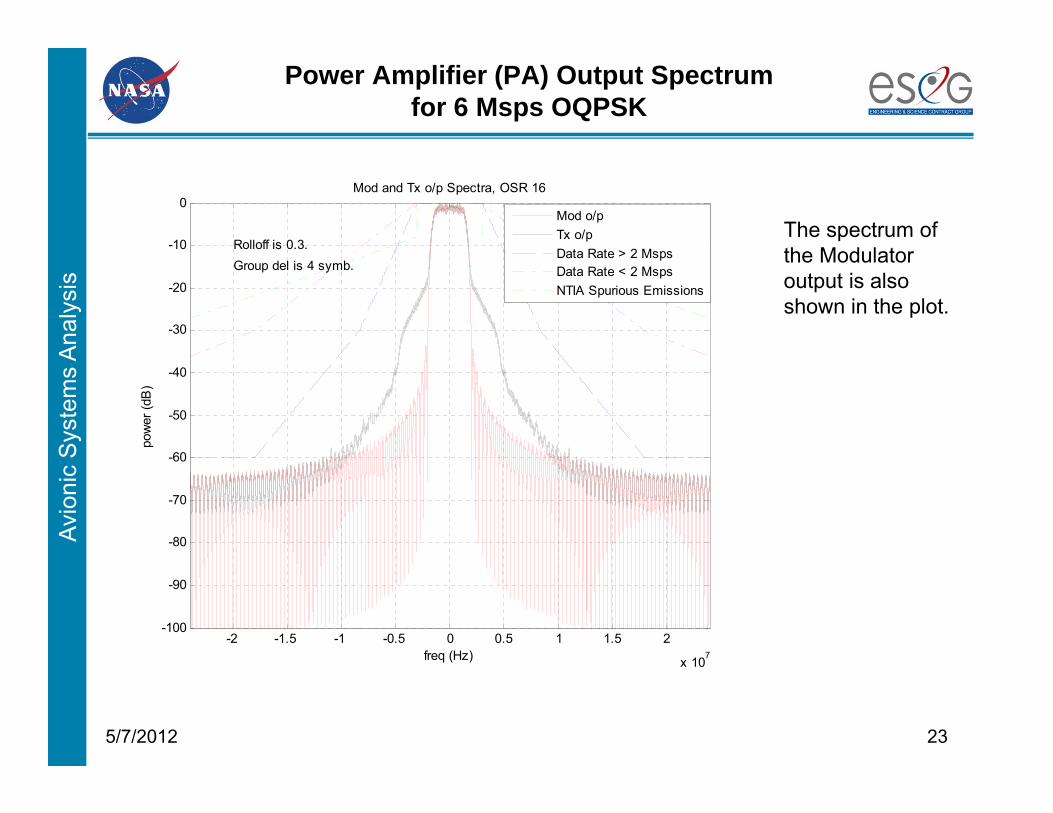
Power Amplifier (PA) Output Spectrumfor 6 Msps OQPSK
235/7/2012
-2 -1.5 -1 -0.5 0 0.5 1 1.5 2
x 107
-100
-90
-80
-70
-60
-50
-40
-30
-20
-10
0Mod and Tx o/p Spectra, OSR 16
freq (Hz)
pow
er (d
B)
Rolloff is 0.3.Group del is 4 symb.
Mod o/pTx o/pData Rate > 2 MspsData Rate < 2 MspsNTIA Spurious Emissions
The spectrum of the Modulator output is also shown in the plot.
Avio
nic
Sys
tem
s A
naly
sis
245/7/2012
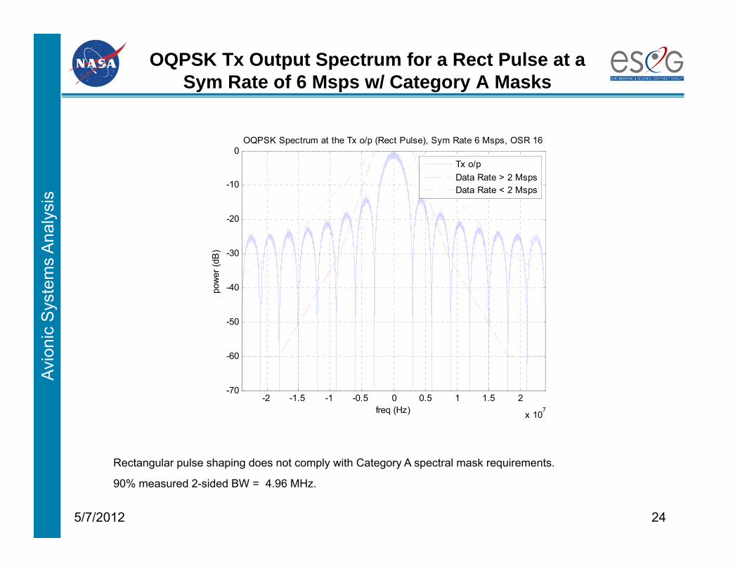
OQPSK Tx Output Spectrum for a Rect Pulse at a Sym Rate of 6 Msps w/ Category A Masks
Rectangular pulse shaping does not comply with Category A spectral mask requirements.
-2 -1.5 -1 -0.5 0 0.5 1 1.5 2
x 107
-70
-60
-50
-40
-30
-20
-10
0OQPSK Spectrum at the Tx o/p (Rect Pulse), Sym Rate 6 Msps, OSR 16
freq (Hz)
pow
er (d
B)
Tx o/pData Rate > 2 MspsData Rate < 2 Msps
90% measured 2-sided BW = 4.96 MHz.
Avio
nic
Sys
tem
s A
naly
sis
255/7/2012
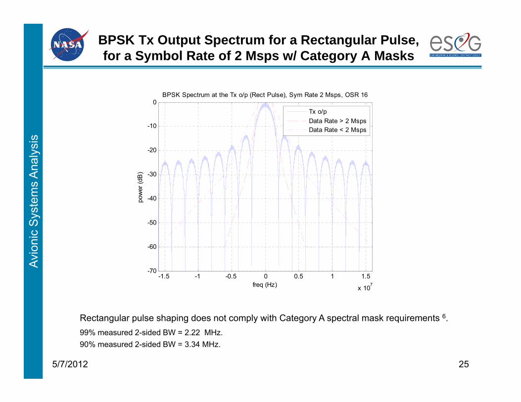
BPSK Tx Output Spectrum for a Rectangular Pulse, for a Symbol Rate of 2 Msps w/ Category A Masks
Rectangular pulse shaping does not comply with Category A spectral mask requirements 6.
-1.5 -1 -0.5 0 0.5 1 1.5
x 107
-70
-60
-50
-40
-30
-20
-10
0BPSK Spectrum at the Tx o/p (Rect Pulse), Sym Rate 2 Msps, OSR 16
freq (Hz)
pow
er (d
B)
Tx o/pData Rate > 2 MspsData Rate < 2 Msps
99% measured 2-sided BW = 2.22 MHz.90% measured 2-sided BW = 3.34 MHz.
Avio
nic
Sys
tem
s A
naly
sis
265/7/2012
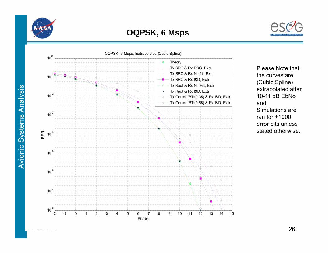
OQPSK, 6 Msps
Please Note that the curves are (Cubic Spline) extrapolated after 10-11 dB EbNoandSimulations are ran for +1000 error bits unless stated otherwise.
-2 -1 0 1 2 3 4 5 6 7 8 9 10 11 12 13 14 1510-8
10-7
10-6
10-5
10-4
10-3
10-2
10-1
100OQPSK, 6 Msps, Extrapolated (Cubic Spline)
Eb/No
BE
R
TheoryTx RRC & Rx RRC, ExtrTx RRC & Rx No filt, ExtrTx RRC & Rx I&D, ExtrTx Rect & Rx No Filt, ExtrTx Rect & Rx I&D, ExtrTx Gauss (BT=0.35) & Rx I&D, ExtrTx Gauss (BT=0.85) & Rx I&D, Extr
Avio
nic
Sys
tem
s A
naly
sis
275/7/2012
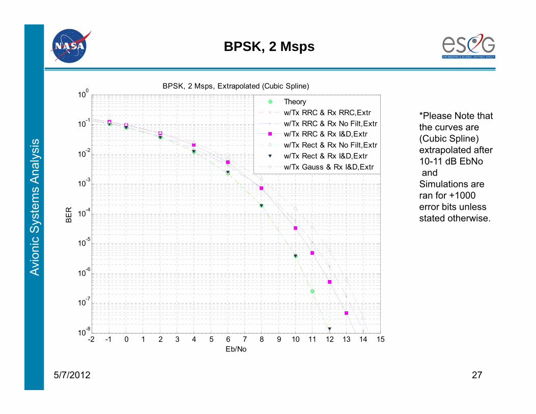
BPSK, 2 Msps
*Please Note that the curves are (Cubic Spline) extrapolated after 10-11 dB EbNoand
Simulations are ran for +1000 error bits unless stated otherwise.
-2 -1 0 1 2 3 4 5 6 7 8 9 10 11 12 13 14 1510-8
10-7
10-6
10-5
10-4
10-3
10-2
10-1
100BPSK, 2 Msps, Extrapolated (Cubic Spline)
Eb/No
BE
R
Theoryw/Tx RRC & Rx RRC,Extrw/Tx RRC & Rx No Filt,Extrw/Tx RRC & Rx I&D,Extrw/Tx Rect & Rx No Filt,Extrw/Tx Rect & Rx I&D,Extrw/Tx Gauss & Rx I&D,Extr
Avio
nic
Sys
tem
s A
naly
sis
285/7/2012
Conclusions
● RRC is more bandwidth efficient than NRZ (i.e., no pulse shaping, rectangular waveform).
● Matching TX and RX filters achieves optimum Bit Error Rate (BER) performance.
● This study provides insight and guidance in the system design for spectral efficiency and Bit Error Rate (BER) performance.
Avio
nic
Sys
tem
s A
naly
sis
References
1. S. Daumont, R. Basel, Y. Lout, "Root-Raised Cosine filter influences on PAPR distribution of single carrier signals", ISCCSP 2008, Malta, 12-14 March 2008.
2. Proakis, J. (1995). Digital Communications (3rd ed.). McGraw-Hill Inc. ISBN 0-07-113814-5.
3. Glover, I.; Grant, P. (2004). Digital Communications (2nd ed.). Pearson Education Ltd. ISBN 0-13-089399-4.
4. Tavares, L.M.; Tavares G.N. (1998) Comments on "Performance of Asynchronous Band-Limited DS/SSMA Systems" . IEICE Trans. Communications., Vol. E81-B, No. 9
5. Châtelain, Benoît, and Gagnon, François, “Peak-to-Average Power Ratio and Intersymbol Interference Reduction by Nyquist Pulse Optimization”
6. Constellation Program Command, Control, Communication, and Information (C3I) Interoperability Standards Book Volume 2: Spectrum and Channel Plan 3.4..2.1 Spectral Emissions Mask for Spurious Emissions (NTIA), p 42 3.4.2.2 Spectral Emissions Mask for Category A Missions, p 43
295/7/2012