Embed Size (px)
Citation preview

Quick Start Guide00825-0100-4148, Rev GA
September 2016
00825-0100-4148_Rev_GA.fm Page 1 Tuesday, September 13, 2016 4:43 PM
Rosemount™ 148 Temperature Transmitter

September 2016Quick Start Guide
00825-0100-4148_Rev_GA.fm Page 2 Tuesday, September 13, 2016 4:43 PM
NOTICEThis guide provides basic guidelines for the Rosemount 148. It does not provide instructions for detailed configuration, diagnostics, maintenance, service, troubleshooting, or installations. Refer to the Rosemount 148 Reference Manual for more instruction. The manual and this guide are also available electronically on EmersonProcess.com/Rosemount.
Explosions could result in death or serious injury.Installation of this transmitter in an explosive environment must be in accordance with the appropriate local, national, and international standards, codes, and practices. Review the Hazardous Locations Certifications for any restrictions associated with a safe installation.
Process leaks may cause harm or result in death.
Install and tighten thermowells or sensors before applying pressure.
Do not remove the thermowell while in operation.
Electrical shock can result in death or serious injury.Avoid contact with the leads and terminals. High voltage that may be present on leads can cause electrical shock.
Conduit/cable entries
Unless marked, the conduit/cable entries in the transmitter housing use a 1/2–14 NPT thread form. Entries marked “M20” are M20 � 1.5 thread form. On devices with multiple conduit entries, all entries have the same thread form. Only use plugs, adapters, glands, or conduit with a compatible thread form when closing entries.
When installing in a Hazardous Location, use only appropriately listed or Ex certified plugs, adapters or glands in cable/conduit entries.
Contents Software installation . . . . . . . . . . . . . . . . . 3Configure . . . . . . . . . . . . . . . . . . . . . . . . . . 3Mount the transmitter . . . . . . . . . . . . . . . 4
Connect the wiring . . . . . . . . . . . . . . . . . . . 6Product Certifications . . . . . . . . . . . . . . . . . 9
2

Quick Start GuideSeptember 2016
00825-0100-4148_Rev_GA.fm Page 3 Tuesday, September 13, 2016 4:43 PM
3
1.0 Software installation1. Install the Rosemount 148 PC Programmer software.
a. Place the Rosemount 148 PC Programmer CD_ROM into the drive.b. Run setup.exe from Windows NT, 2000, or XP.
2. When first using the Rosemount 148 PC software, configure the appropriate COM ports by selecting Port Settings from the Communicate menu.
3. Install MACTek Modem drivers completely before beginning bench configuration on the Rosemount 148 system.
NoteThe software defaults to the first available COM port.
2.0 ConfigureThe Rosemount 148 must be configured for certain basic variables to operate. In many cases, all of these variables are pre-configured at the factory. Configuration may be required if the transmitter is not configured or if the configuration variables need revision. This can be done in two ways: by ordering factory-configuration by Emerson™ Process Management, or by using the Rosemount 148 PC Programming interface in a bench configuration setting.
The Rosemount 148 PC Programming Kit includes configuration software and a communication modem. The Rosemount 148 device will need an external power supply of 12–42.4 Vdc for configuration.1. Hook up the transmitter and a load resistor (250–1100 ohms) wired in series
with the power supply.
2. Attach the Modem in parallel with the load resistor and connect it to the PC.
See "Table 1: Rosemount 148 Programming Kit spare part numbers" for spares kit and re-order numbers. For more information, refer to the Rosemount 148 Reference Manual.
Table 1. Rosemount 148 Programming Kit spare part numbers
2.1 Verify transmitter configurationIf the transmitter has a sensor connected (either a test sensor or actual installation hardware), the configuration can be checked using the Information tab on the Rosemount 148 PC Programmer interface. Select Refresh to update the status and confirm that the transmitter has been configured correctly. If there are any problems, refer to the Rosemount 148 Reference Manual for troubleshooting suggestions.
Product description Part number
Programming Software (CD) 00148-1601-0002
Rosemount 148 Programmer Kit - USB 00148-1601-0003
Rosemount 148 Programmer Kit - Serial 00148-1601-0004

September 2016Quick Start Guide
00825-0100-4148_Rev_GA.fm Page 4 Tuesday, September 13, 2016 4:43 PM
3.0 Mount the transmitterTo prevent moisture from draining into the transmitter housing, mount the transmitter at a high point in the conduit run.
3.1 Typical European and Asia Pacific installation
Head mount transmitter with DIN plate style sensor1. Attach the thermowell to the pipe or process container wall. Install and
tighten the thermowell before applying process pressure.
2. Assemble the transmitter to the sensor. a. Push the transmitter mounting screws through the sensor mounting plate.b. Insert the snap rings (optional) into the transmitter mounting screw
groove.
3. Wire the sensor to the transmitter.
4. Insert the transmitter-sensor assembly into the connection head. a. Thread the transmitter mounting screw into the connection head
mounting holes. b. Assemble the extension to the connection head. c. Insert the assembly into the thermowell.
5. Slip the shielded cable through the cable gland.
6. Attach a cable gland into the shielded cable.
7. Insert the shielded cable leads into the connection head through the cable entry.
8. Connect and tighten the cable gland.
9. Connect the shielded power cable leads to the transmitter power terminals. Avoid contact with sensor leads and sensor connections. (See Connect the wiring for instructions on grounding the shield wire.)
10. Install and tighten the connection head cover. Enclosure covers must be fully engaged to meet explosion-proof requirements.
A. Rosemount 148 Transmitter D. Transmitter mounting screwsB. Connection head E. Integral mount sensor with flying leadsC. Thermowell F. Extension
A B C
D
E F
4

Quick Start GuideSeptember 2016
00825-0100-4148_Rev_GA.fm Page 5 Tuesday, September 13, 2016 4:43 PM
5
3.2 Typical north and south american installation
Head mount transmitter with threaded sensor1. Attach the thermowell to the pipe or process container wall. Install and tighten
thermowells before applying process pressure.
2. Attach necessary extension nipples and adapters to the thermowell.
3. Seal the nipple and adapter threads with silicone tape.
4. Screw the sensor into the thermowell. Install drain seals if required for severe environments or to satisfy code requirements.
5. Pull the sensor wiring leads through the universal head and transmitter.
6. Mount the transmitter in the universal head by threading the transmitter mounting screws into the universal head mounting holes.
7. Mount the transmitter-sensor assembly into the thermowell. Seal adapter threads with silicone tape.
8. Install conduit for field wiring to the conduit entry of the universal head. Seal conduit threads with silicone tape.
9. Pull the field wiring leads through the conduit into the universal head.
10. Attach the sensor and power leads to the transmitter while avoiding contact with other terminals.
11. Install and tighten the universal head cover.
NoteEnclosure covers must be fully engaged to meet explosion-proof requirements.
A. Threaded thermowell D. Universal headB. Threaded style sensor E. Conduit entryC. Standard extension
A B D
C E

September 2016Quick Start Guide
00825-0100-4148_Rev_GA.fm Page 6 Tuesday, September 13, 2016 4:43 PM
3.3 Mounting to a DIN rail
4.0 Connect the wiring Wiring diagrams are located on the top label of the transmitter. An external power supply is required to operate the transmitter. The power required across the transmitter power terminals is 12 to 42.4 Vdc
(the power terminals are rated to 42.4 Vdc). To prevent damaging the transmitter, do not allow terminal voltage to drop below 12.0 Vdc when changing the configuration parameters.
4.1 Power the transmitter1. Connect the positive power lead to the “+” terminal.
2. Connect the negative power lead to the “–” terminal.
3. Tighten the terminal screws.
4. Apply power (12–42 Vdc).
Figure 1. Power, Communication, and Sensor Terminals
A. Sensor terminalsB. Power/communication terminals
To attach the Rosemount 148H to a DIN rail, assemble the appropriate rail mounting kit (part number 00248-1601-0001) to the transmitter as shown.
A. Mounting hardwareB. TransmitterC. Rail clip
A
B
C
A
B
+–
6

Quick Start GuideSeptember 2016
00825-0100-4148_Rev_GA.fm Page 7 Tuesday, September 13, 2016 4:43 PM
4.2 Ground the transmitter
Ungrounded thermocouple, and RTD/Ohm inputs
Each process installation has different requirements for grounding. Use the grounding options recommended by the facility for the specific sensor type or begin with grounding Option 1 (the most common).
Option 1 (for grounded housing):1. Connect sensor wiring shield to the transmitter housing.
2. Ensure the sensor shield is electrically isolated from surrounding fixtures that may be grounded.
3. Ground signal wiring shield at the power supply end.
Option 2 (for ungrounded housing):1. Connect signal wiring shield to the sensor wiring shield.
2. Ensure the two shields are tied together and electrically isolated from the transmitter housing.
3. Ground shield at the power supply end only.
4. Ensure the sensor shield is electrically isolated from the surrounding grounded fixtures.
Option 3 (for grounded or ungrounded housing): 1. Ground sensor wiring shield at the sensor, if possible.
2. Insure that the sensor wiring and signal wiring shields are electrically isolated from the transmitter housing.
3. Do not connect the signal wiring shield to the sensor wiring shield.
A. Sensor wiresB. Transmitters
C. 4–20 mA loopD. Shield ground point
A. Sensor wiresB. Transmitters
C. 4–20 mA loopD. Shield ground point
A
B
D
C
D
B
A C
7
September 2016Quick Start Guide
00825-0100-4148_Rev_GA.fm Page 8 Tuesday, September 13, 2016 4:43 PM
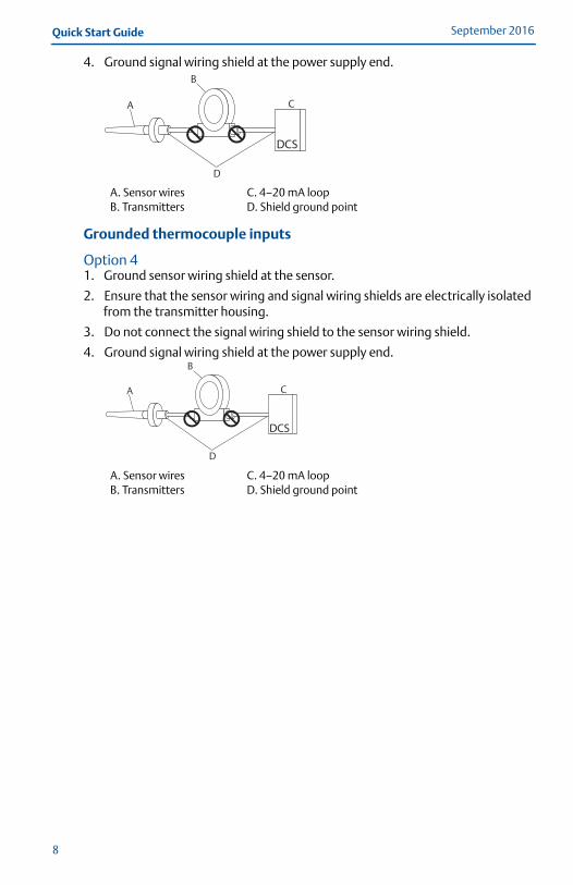
4. Ground signal wiring shield at the power supply end.
Grounded thermocouple inputs
Option 41. Ground sensor wiring shield at the sensor.
2. Ensure that the sensor wiring and signal wiring shields are electrically isolated from the transmitter housing.
3. Do not connect the signal wiring shield to the sensor wiring shield.
4. Ground signal wiring shield at the power supply end.
A. Sensor wiresB. Transmitters
C. 4–20 mA loopD. Shield ground point
A. Sensor wiresB. Transmitters
C. 4–20 mA loopD. Shield ground point
A
B
D
C
A
B
D
C
8

Quick Start GuideSeptember 2016
00825-0100-4148_Rev_GA.fm Page 9 Tuesday, September 13, 2016 4:43 PM
5.0 Product CertificationsRev 1.5
5.1 Approved Manufacturing LocationsEmerson Process Management - Chanhassen, Minnesota, USARosemount Temperature GmbH - GermanyEmerson Process Management Asia Pacific - Singapore
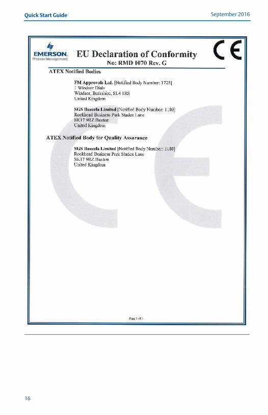
5.2 European Directive InformationA copy of the EC Declaration of Conformity can be found at the end of the Quick Start Guide. The most recent revision of the EC Declaration of Conformity can be found at EmersonProcess.com/Rosemount.
5.3 Ordinary Location Certification from FM ApprovalsAs standard, the transmitter has been examined and tested to determine that the design meets the basic electrical, mechanical, and fire protection requirements by FM Approvals, a nationally recognized test laboratory (NRTL) as accredited by the Federal Occupational Safety and Health Administration (OSHA).
North AmericaE5 FM Explosionproof, Dust-Ignitionproof, and Nonincendive
Certificate: 3032198Standards: FM Class 3600:2011, FM Class 3611:2004, FM Class 3615:2006,
FM Class 3810:2005, IEC 60529: 2004, NEMA® - 250: 1991Markings: XP CL I, DIV 1, GP B, C, D; DIP CL II/III, DIV 1, GP E, F, G; NI CL I, DIV 2, GP A, B,
C, D; T5(–50 °C ≤ Ta ≤ +85 °C); when installed per Rosemount drawing 00148-1065; Type 4X; IP66/68
I5 FM Intrinsic Safety and NonincendiveCertificate: 3032198Standards Used: FM Class 3600:2011, FM Class 3610:2010, FM Class 3611:2004, FM
Class 3810:2005, IEC 60529: 2004, NEMA - 250: 1991Markings: IS CL I/II/III, DIV 1, GP A, B, C, D, E, F, G; NI CL1, DIV 2, GP A, B, C, D; T6(–50 °C
≤ Ta ≤ +40 °C), T5(–50 °C ≤ Ta ≤ +75 °C) when installed per Rosemount drawing 00148-1055; Type 4X; IP66/68
Special Conditions for Safe Use (X):1. When no enclosure option is selected, the Rosemount 148 Transmitter shall be installed
in an enclosure meeting the requirements of ANSI/ISA S82.01 and S82.03 or other applicable ordinary location standards.
2. No enclosure or Buz Head option cannot be selected to maintain a Type 4X rating.3. Enclosure option must be selected to maintain a Type 4 Rating.
I6 CSA Intrinsic Safety and Division 2Certificate:1091070Standards: CAN/CSA C22.2 No. 0-M90, CSA Std. C22.2 No. 25-1966, CAN/CSA C22.2
No. 94-M91, CAN/CSA C22.2 No. 157-92, CSA C22.2 No. 213-M1987, C22.2 No 60529-05
Markings: IS CL I, DIV 1 GP A, B, C, D when installed per Rosemount drawing 00248-1056; Suitable for CL I DIV 2 GP A, B, C, D when installed per Rosemount drawing 00248-1055; T6(–50 °C ≤ Ta ≤ +40 °C), T5(–50 °C ≤ Ta ≤ +60 °C); Type 4X, IP66/68 for enclosure options “A”, “G”, “H”, “U”; Seal not required (See drawing 00248-1066).
9

September 2016Quick Start Guide
00825-0100-4148_Rev_GA.fm Page 10 Tuesday, September 13, 2016 4:43 PM
10
K6 CSA Explosionproof, Intrinsic Safety, and Division 2Certificate: 1091070Standards: CAN/CSA C22.2 No. 0-M90, CSA Std. C22.2 No. 25-1966, CSA Std. C22.2 No.
30-M1986, CAN/CSA C22.2 No. 94-M91, CSA Std. C22.2 No.142-M1987, CAN/CSA C22.2 No. 157-92, CSA C22.2 No. 213-M1987, C22.2 No 60529-05
Markings: XP CL I/II/III, DIV 1, GP B, C, D, E, F, G when installed per Rosemount drawing 00248-1066; IS CL I, DIV 1 GP A, B, C, D when installed per Rosemount drawing 00248-1056; Suitable for CL I DIV 2 GP A, B, C, D when installed per Rosemount drawing 00248-1055; T6(–50 °C ≤ Ta ≤ +40 °C), T5(–50 °C ≤ Ta ≤ +60 °C); Type 4X, IP66/68 for enclosure options “A”, “G”, “H”, “U”; Seal not required (See drawing 00248-1066).
EuropeE1 ATEX Flameproof
Certificate: FM12ATEX0065X Standards: EN 60079-0: 2012, EN 60079-1: 2007, EN 60529:1991 +A1:2000Markings: II 2 G Ex d IIC T6…T1 Gb, T6(-50 °C ≤ Ta ≤ +40 °C), T5…T1(-50 °C ≤ Ta ≤
+60 °C)See Table 2 at the end of the Product Certifications section for process temperatures
Special Conditions for Safe Use (X): 1. See certificate for ambient temperature range.2. The non-metallic label may store an electrostatic charge and become a source of
ignition in Group III environments.3. Guard the LCD cover against impact energies greater than 4 joules.4. Flameproof joints are not intended for repair.5. A suitable certified Ex d or Ex tb enclosure is required to be connected to temperature
probes with Enclosure option “N”.6. Care shall be taken by the end user to ensure that the external surface temperature on
the equipment and the neck of DIN Style Sensor probe does not exceed 130 °C.7. Non-Standard Paint options may cause risk from electrostatic discharge. Avoid
installations that cause electrostatic build-up on painted surfaces, and only clean the painted surfaces with a damp cloth. If paint is ordered through a special option code, contact the manufacturer for more information.
I1 ATEX Intrinsic SafetyCertificate: Baseefa08ATEX0030XStandards: EN 60079-0: 2012, EN 60079-11: 2012Markings: II 1 G Ex ia IIC T5/T6 Ga, T5(-60 °C ≤ Ta ≤ +80 °C), T6(-60 °C ≤ Ta ≤ +60 °C)See Table 3 at the end of the Product Certifications section for entity parameters
Special Condition for Safe Use (X):1. The apparatus must be installed in an enclosure which affords it a degree of protection
of at least IP20. Non-metallic enclosures must have a surface resistance of less than 1 GΩ; light alloy or zirconium enclosures must be protected from impact and friction when installed.
N1 ATEX Type n - with enclosureCertificate: BAS00ATEX3145Standards: EN 60079-0:2012, EN 60079-15:2010Markings: II 3 G Ex nA IIC T5 Gc (-40 °C ≤ Ta ≤ +70 °C);
Quick Start GuideSeptember 2016
00825-0100-4148_Rev_GA.fm Page 11 Tuesday, September 13, 2016 4:43 PM
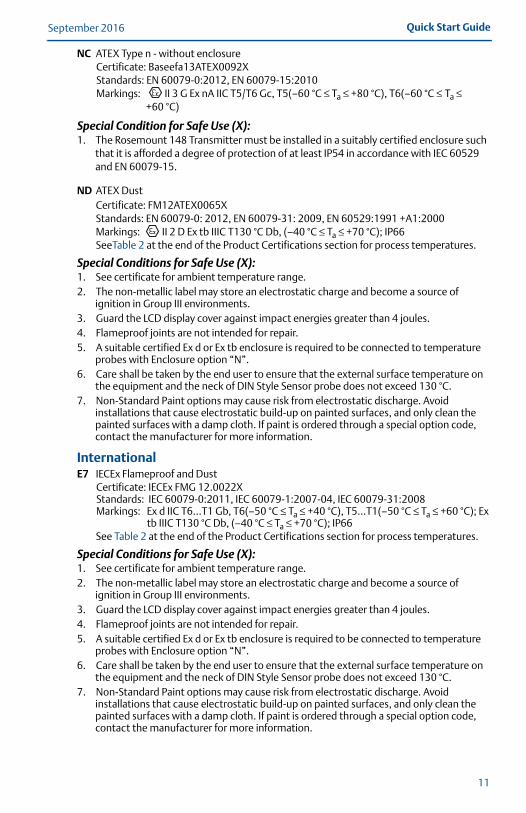
NC ATEX Type n - without enclosureCertificate: Baseefa13ATEX0092XStandards: EN 60079-0:2012, EN 60079-15:2010Markings: II 3 G Ex nA IIC T5/T6 Gc, T5(–60 °C ≤ Ta ≤ +80 °C), T6(–60 °C ≤ Ta ≤
+60 °C)
Special Condition for Safe Use (X):1. The Rosemount 148 Transmitter must be installed in a suitably certified enclosure such
that it is afforded a degree of protection of at least IP54 in accordance with IEC 60529 and EN 60079-15.
ND ATEX DustCertificate: FM12ATEX0065X Standards: EN 60079-0: 2012, EN 60079-31: 2009, EN 60529:1991 +A1:2000Markings: II 2 D Ex tb IIIC T130 °C Db, (–40 °C ≤ Ta ≤ +70 °C); IP66SeeTable 2 at the end of the Product Certifications section for process temperatures.
Special Conditions for Safe Use (X): 1. See certificate for ambient temperature range.2. The non-metallic label may store an electrostatic charge and become a source of
ignition in Group III environments.3. Guard the LCD display cover against impact energies greater than 4 joules.4. Flameproof joints are not intended for repair.5. A suitable certified Ex d or Ex tb enclosure is required to be connected to temperature
probes with Enclosure option “N”.6. Care shall be taken by the end user to ensure that the external surface temperature on
the equipment and the neck of DIN Style Sensor probe does not exceed 130 °C.7. Non-Standard Paint options may cause risk from electrostatic discharge. Avoid
installations that cause electrostatic build-up on painted surfaces, and only clean the painted surfaces with a damp cloth. If paint is ordered through a special option code, contact the manufacturer for more information.
InternationalE7 IECEx Flameproof and Dust
Certificate: IECEx FMG 12.0022XStandards: IEC 60079-0:2011, IEC 60079-1:2007-04, IEC 60079-31:2008Markings: Ex d IIC T6…T1 Gb, T6(–50 °C ≤ Ta ≤ +40 °C), T5…T1(–50 °C ≤ Ta ≤ +60 °C); Ex
tb IIIC T130 °C Db, (–40 °C ≤ Ta ≤ +70 °C); IP66See Table 2 at the end of the Product Certifications section for process temperatures.
Special Conditions for Safe Use (X):1. See certificate for ambient temperature range.2. The non-metallic label may store an electrostatic charge and become a source of
ignition in Group III environments.3. Guard the LCD display cover against impact energies greater than 4 joules.4. Flameproof joints are not intended for repair.5. A suitable certified Ex d or Ex tb enclosure is required to be connected to temperature
probes with Enclosure option “N”.6. Care shall be taken by the end user to ensure that the external surface temperature on
the equipment and the neck of DIN Style Sensor probe does not exceed 130 °C.7. Non-Standard Paint options may cause risk from electrostatic discharge. Avoid
installations that cause electrostatic build-up on painted surfaces, and only clean the painted surfaces with a damp cloth. If paint is ordered through a special option code, contact the manufacturer for more information.
11
September 2016Quick Start Guide
00825-0100-4148_Rev_GA.fm Page 12 Tuesday, September 13, 2016 4:43 PM
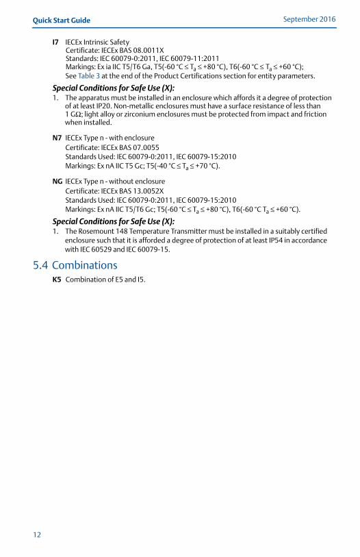
I7 IECEx Intrinsic SafetyCertificate: IECEx BAS 08.0011XStandards: IEC 60079-0:2011, IEC 60079-11:2011Markings: Ex ia IIC T5/T6 Ga, T5(-60 °C ≤ Ta ≤ +80 °C), T6(-60 °C ≤ Ta ≤ +60 °C);See Table 3 at the end of the Product Certifications section for entity parameters.
Special Conditions for Safe Use (X):1. The apparatus must be installed in an enclosure which affords it a degree of protection
of at least IP20. Non-metallic enclosures must have a surface resistance of less than 1 GΩ; light alloy or zirconium enclosures must be protected from impact and friction when installed.
N7 IECEx Type n - with enclosureCertificate: IECEx BAS 07.0055Standards Used: IEC 60079-0:2011, IEC 60079-15:2010Markings: Ex nA IIC T5 Gc; T5(-40 °C ≤ Ta ≤ +70 °C).
NG IECEx Type n - without enclosureCertificate: IECEx BAS 13.0052XStandards Used: IEC 60079-0:2011, IEC 60079-15:2010Markings: Ex nA IIC T5/T6 Gc; T5(-60 °C ≤ Ta ≤ +80 °C), T6(-60 °C Ta ≤ +60 °C).
Special Conditions for Safe Use (X):1. The Rosemount 148 Temperature Transmitter must be installed in a suitably certified
enclosure such that it is afforded a degree of protection of at least IP54 in accordance with IEC 60529 and IEC 60079-15.
5.4 CombinationsK5 Combination of E5 and I5.
12

Quick Start GuideSeptember 2016
00825-0100-4148_Rev_GA.fm Page 13 Tuesday, September 13, 2016 4:43 PM
5.5 TablesTable 2. Process Temperature
Temperature class
Ambient temperature
Process temperature w/o LCD display cover (°C)
No ext. 3-in. 6-in. 9-in.
T6 –50 °C to +40 °C 55 55 60 65
T5 –50 °C to +60 °C 70 70 70 75
T4 –50 °C to +60 °C 100 110 120 130
T3 –50 °C to +60 °C 170 190 200 200
T2 –50 °C to +60 °C 280 300 300 300
T1 –50 °C to +60 °C 440 450 450 450
Table 3. Entity Parameter
Parameters HART loop terminals + and – Sensor terminals 1 to 4
Voltage Ui 30 V 45 V
Current Ii 130 mA 26 mA
Power Pi 1 W 290 mW
Capacitance Ci 3.6 nF 2.1 nF
Inductance Li 0 mH 0 μH
13

September 2016Quick Start Guide
00825-0100-4148_Rev_GA.fm Page 14 Tuesday, September 13, 2016 4:43 PM
14
Figure 2. Rosemount 148 Declaration of Conformity

Quick Start GuideSeptember 2016
00825-0100-4148_Rev_GA.fm Page 15 Tuesday, September 13, 2016 4:43 PM
15
September 2016Quick Start Guide
00825-0100-4148_Rev_GA.fm Page 16 Tuesday, September 13, 2016 4:43 PM
16

Quick Start GuideSeptember 2016
00825-0100-4148_Rev_GA.fm Page 17 Tuesday, September 13, 2016 4:43 PM
China RoHS Rosemount 148
List of Rosemount 148 Parts with China RoHS Concentration above MCVs
Part Name
Hazardous Substances
Lead (Pb)
Mercury (Hg)
Cadmium (Cd)
Hexavalent Chromium
(Cr +6)
Polybrominated biphenyls
(PBB)
Polybrominated diphenyl ethers
(PBDE)
Electronics Assembly
X O O O O O
Housing Assembly
O O O X O O
Sensor Assembly
X O O O O O
SJ/T11364This table is proposed in accordance with the provision of SJ/T11364. O: GB/T 26572 O: Indicate that said hazardous substance in all of the homogeneous materials for this part is below the limit requirement of GB/T 26572. X: GB/T 26572 X: Indicate that said hazardous substance contained in at least one of the homogeneous materials used for this part is above the limit requirement of GB/T 26572.
17

00825-0100-4148_Rev_GA.fm Page 18 Tuesday, September 13, 2016 4:43 PM
Global HeadquartersEmerson Process Management 6021 Innovation Blvd.Shakopee, MN 55379, USA
+1 800 999 9307 or +1 952 906 8888+1 952 949 7001 [email protected]
North America Regional OfficeEmerson Process Management 8200 Market Blvd.Chanhassen, MN 55317, USA
+1 800 999 9307 or +1 952 906 8888
+1 952 949 7001
Latin America Regional OfficeEmerson Process Management 1300 Concord Terrace, Suite 400Sunrise, FL 33323, USA
+1 954 846 5030
+1 954 846 5121
[email protected]/company/Emerson-Process-Management
Twitter.com/Rosemount_News
Facebook.com/Rosemount
Youtube.com/user/RosemountMeasurement
Google.com/+RosemountMeasurement
Standard Terms and Conditions of Sale can be found at www.Emerson.com/en-us/pages/Terms-of-Use.aspxThe Emerson logo is a trademark and service mark of Emerson Electric Co.Rosemount and Rosemount logotype are trademarks of Emerson Process Management.NEMA is a registered trademark and service mark of the National Electrical Manufacturers Association.All other marks are the property of their respective owners.© 2016 Emerson Process Management. All rights reserved.
Europe Regional OfficeEmerson Process Management Europe GmbHNeuhofstrasse 19a P.O. Box 1046CH 6340 BaarSwitzerland
+41 (0) 41 768 6111
+41 (0) 41 768 6300
Asia Pacific Regional OfficeEmerson Process Management Asia Pacific Pte Ltd1 Pandan CrescentSingapore 128461
+65 6777 8211
+65 6777 0947 [email protected]
Middle East and Africa Regional OfficeEmerson Process Management Emerson FZE P.O. Box 17033,Jebel Ali Free Zone - South 2Dubai, United Arab Emirates
+971 4 8118100
+971 4 [email protected]
Quick Start Guide00825-0100-4148, Rev GA
September 2016
*00825-0100-4148*