Embed Size (px)
Citation preview

Product Data SheetAugust 2017
00813-0100-4570, Rev CA
Rosemount™ 5708 3D Solids Scanner
Make informed decisions about inventory control with unique, dust-penetrating technology for measuring bulk solids and powders accurately.
Take the guesswork out of measuring the level, volume, and with multiple point measurement.
Operate with minimum maintenance on any material stored in a variety of silos, bins, and warehouses.
Use 3D visualization to determine exactly what is going on inside your vessel.

Rosemount 5708 3D Solids Scanner August 2017
OverviewMeasurement principle
The Rosemount 5708 uses an acoustic phased-array technology.
The Rosemount 5708 delivers accurate volume and level measurement of bulk solids and powders – regardless of material type, product characteristics, storage silo type, size, or harshness of the storage environment.
The device includes an integral array of three antennas that generate unique dust-penetrating low frequency acoustic waves and receive echoes from the contents. Using these antennas, the unit measures not only the time/distance of each echo, but also its direction.
Collecting multiple echoes from different directions and distances enables the Rosemount 5708 to accurately calculate the volume of stored material. It also enables the Rosemount 3DVision/3DMultiVision™ software to generate the 3D visualization of the material.
The acoustic waves combined with self-cleaning capabilities prevent material from adhering to the internal workings of the antenna array, ensuring long-term reliable performance with very low maintenance requirements, regardless of harsh dusty conditions.
Contents
Overview . . . . . . . . . . . . . . . . . . . . . . . . . . . . . . . . . . . . . . . . 2
Monitor multiple vessels easily . . . . . . . . . . . . . . . . . . . . . 3
Ordering Information . . . . . . . . . . . . . . . . . . . . . . . . . . . . . 5
Specifications . . . . . . . . . . . . . . . . . . . . . . . . . . . . . . . . . . . 11
Accessories . . . . . . . . . . . . . . . . . . . . . . . . . . . . . . . . . . . . . . . 8
Software Installation Requirements . . . . . . . . . . . . . . . .16
Product certifications . . . . . . . . . . . . . . . . . . . . . . . . . . . . .17
Dimensional drawings . . . . . . . . . . . . . . . . . . . . . . . . . . . .22
Rosemount 5708
Rosemount 5708 in a system
2 Emerson.com/Rosemount

Rosemount 5708 3D Solids ScannerAugust 2017
Monitor multiple vessels easily
Monitoring vessels across multiple sites and remote geographic areas is a challenge. You need accurate information that is based on real-time conditions. Rosemount 3DVision/3DMultiVision software provides sophisticated analysis of current conditions as well as historical data that allows you to improve your workflows while reducing operating costs.
The software enables multiple accesses and is comprised of two components: a server and a client. The data is stored on the server computer which generates the reports and transfers the information to all connected Rosemount 3DVision clients.
Authorized users, connected to the same LAN or via external connections (WAN), have access to both real-time and historical data for all Rosemount 5708 connected to the server.
The Rosemount 3DVision Client is a graphical and interactive program, allowing the user to receive online data from devices, view a 3D visualization of the material stored in the vessels, add or remove sites, vessels, and devices and manage alerts and reports.
Internet
Internet
Local IP Address192.168.1.100
Port 22222
3DVision ServerComputer
Remote Client(WAN)
Local IP Address192.168.1.104
Local IP Address192.168.1.105
Local Clients (LAN)
Local IP Address192.168.1.106
External Static IPAddress
212.235.113.24
INTERNET
RouterSwitch
Rosemount 3DVision computer topology
3Emerson.com/Rosemount

Rosemount 5708 3D Solids Scanner August 2017
Application examplesThe Rosemount 5708 enables efficient process measurement and true inventory management of bulk solid materials used in a broad range of industrial applications.
The devices can measure practically any kind of solid material, stored in a variety of containers, including large bins, bulk solid storage rooms, and warehouses, loads that randomly form over time inside silos, and many other challenging applications that were not possible previously. The Rosemount 5708 can measure ranges of up to 230 feet (70 m).
Rosemount 5708L
Highly accurate readings of level
Provides the average level of the stored contents and average distance from the device to the surface of the material
Rosemount 5708V
Highly accurate readings of level and volume
Provides minimum and maximum level/distance measurements
Appropriate for vessels up to 40 feet (12 m) in diameter
Rosemount 5708S
Highly accurate readings of level and volume
Monitors inventory in large vessels
Provides minimum and maximum level/distance measurements
Unlimited vessel diameter when using Rosemount 5708S in a system
Generates 3D visualization of the stored contents
4 Emerson.com/Rosemount

Rosemount 5708 3D Solids ScannerAugust 2017
Ordering Information
The Rosemount 5708 incorporate best-in-class solutions for previously inaccessible process measurement applications in many manufacturing sectors. Characteristics include:
• Multiple point measurement• Dust-penetrating, acoustic-based low-frequency technology• Unaffected by material type• Long measurement range
Additional information
Specifications: see “Functional specifications” on page 11
Certifications: see “Product certifications” on page 17
Dimensional drawings: see “Dimensional drawings” on page 22
Specification and selection of product materials, options, or components must be made by the purchaser of the equipment. See page 13 for more information on Material Selection.
Table 1. Rosemount 5708 Ordering Information
The starred offerings (★) represent the most common options and should be selected for best delivery. The non-starred offerings are subject to additional delivery lead time.
Model Product description
5708 3D Solids Scanner ★
Model type
LNN Average level measurement ★
VEN Volume measurement up to 39.4 feet (12 m) in diameter ★
SEV Volume measurement with visualization. ★
Housing material
A Polyurethane covered aluminum ★
Signal output
B(1) 4–20 mA and RS-485 with Modbus® ★
Conduit/cable threads
1 1/2-in. NPT adapter (qty = 2) supplied separately in the box ★
2 M20 x 1.5 thread ★
Hazardous locations certifications
NA(2) No hazardous locations certifications ★
I1 ATEX intrinsic safety ★
I3 NEPSI intrinsic safety ★
5Emerson.com/Rosemount
Rosemount 5708 3D Solids Scanner August 2017
I5 cFMus intrinsic safety ★
I2 INMETRO Intrinsic Safety
I7 IECEx Intrinsic Safety
IP KOSHA Intrinsic Safety
IM Technical Regulations Customs Union (EAC) Intrinsic Safety
IW PESO Intrinsic Safety
Process operating temperature
S Standard temperature –40... +185 °F (–40... +85 °C) ★
H High temperature –40... +356 °F (–40... +180 °C) (no hazardous locations certifications available)
Material of antenna construction
P Polyurethane painted aluminum antenna ★
8 PTFE coated aluminum antenna
H High temperature painted aluminum antenna
I(3) High temperature painted aluminum antenna supplied with 12-in (30 cm) extended cable
J(4) High temperature painted aluminum antenna for angle adapter supplied with 16-in. (40 cm) extended cable
K(3) High temperature painted aluminum antenna supplied with 20-in. (50 cm) extended cable
L(3) High temperature painted aluminum antenna supplied with 39-in. (100 cm) extended cable
M(5) High temperature painted aluminum antenna for ESP supplied with 59-in. (150 cm) extended cable
O(3) High temperature painted aluminum antenna supplied with 78-in. (200 cm) extended cable
R(3) High temperature painted aluminum antenna supplied with 118-in. (300 cm) extended cable
O-ring material
B Nitrile butadiene for standard temperature ★
S Silicone for high temperature
Options (include with selected model number)
Mounting plate/assembly
Mounting plate
4AA 4-in. (100 mm) - Matches ANSI 4-in., Class 150 connection; painted carbon steel
4AX High temperature, 4-in. (100 mm) - Matches ANSI 4-in., Class 150 connection; painted carbon steel
6AA 6-in. (150 mm) - Matches ANSI 6-in., Class 150 connection; painted carbon steel
6AX High temperature, 6-in. (150 mm) - Matches ANSI 6-in., Class 150 connection; painted carbon steel
8AA 8-in. (200 mm) - Matches ANSI 8-in., Class 150 connection; painted carbon steel
8AX High temperature, 8-in. (200 mm) - Matches ANSI 8-in., Class 150 connection; painted carbon steel
TAA 10-in. (250 mm) - Matches ANSI 10-in., Class 150 connection; painted carbon steel
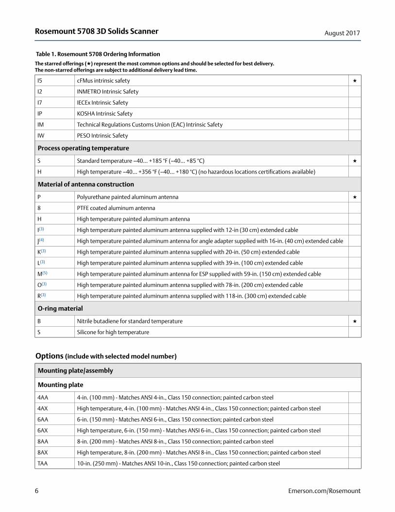
Table 1. Rosemount 5708 Ordering Information
The starred offerings (★) represent the most common options and should be selected for best delivery. The non-starred offerings are subject to additional delivery lead time.
6 Emerson.com/Rosemount
Rosemount 5708 3D Solids ScannerAugust 2017
TAX High temperature, 10-in. (250 mm) - Matches ANSI 10-in., Class 150 connection; painted carbon steel
4DA 100 - Matches DN 100, PN 16 connection; painted carbon steel
4DX High temperature, 100 - Matches DN 100, PN 16 connection; painted carbon steel
6DA 150 - Matches DN 150, PN 16 connection; painted carbon steel
6DX High temperature, 150 - Matches DN 150, PN 16 connection; painted carbon steel
8DA 200 - Matches DN 200, PN 16 connection; painted carbon steel
8DX High temperature, 200 - Matches DN 200, PN 16 connection; painted carbon steel
TDA 250 - Matches DN 250, PN 16 connection; painted carbon steel
TDX High temperature, 250 - Matches DN 250, PN 16 connection; painted carbon steel
Mounting assembly (see page 28)
A00 0° Steel powder coated mounting assembly (supplied with mounting plate)
A05 5° Steel powder coated mounting assembly (supplied with mounting plate)
A10 10° Steel powder coated mounting assembly (supplied with mounting plate)
A15 15° Steel powder coated mounting assembly (supplied with mounting plate)
A20 20° Steel powder coated mounting assembly (supplied with mounting plate)
A30 30° Steel powder coated mounting assembly (supplied with mounting plate)
B00 High temperature 0° steel powder coated mounting assembly (supplied with mounting plate)
B05 High temperature 5° steel powder coated mounting assembly (supplied with mounting plate)
B10 High temperature 10° steel powder coated mounting assembly (supplied with mounting plate)
B15 High temperature 15° steel powder coated mounting assembly (supplied with mounting plate)
B20 High temperature 20° steel powder coated mounting assembly (supplied with mounting plate)
B30 High temperature 30° steel powder coated mounting assembly (supplied with mounting plate)
Extended product warranty
WR5(6) 5-year limited warranty
Example model string: 5708-SEV-A-B-2-I1-S-P-B means volume measurement with visualization, ATEX intrinsic safety, with standard operation temperature antenna and O-ring.
1. The Rosemount 5708 supports communication with the Modbus RTU and provides the holding registers only. It is not used for configuration.
2. Use when ordering high temperature antenna or for non-hazardous locations.
3. Order mechanical parts separately (see Table 2).
4. Angle adapter must be selected separately (see Table 2).
5. ESP hopper mounting bracket must be selected separately (see Table 2).
6. Check with your local Emerson™ office for a 2-year extended warranty when prepaid startup is ordered with the Rosemount 5708.
Table 1. Rosemount 5708 Ordering Information
The starred offerings (★) represent the most common options and should be selected for best delivery. The non-starred offerings are subject to additional delivery lead time.
7Emerson.com/Rosemount

Rosemount 5708 3D Solids Scanner August 2017
Accessories Table 2. Accessories Ordering Information The starred options (★) represent the most common options and should be selected for best delivery. The non-starred offerings are subject to additional delivery lead time.
System controller and LinkPro (see page 14)
05708-4000-0001 Rosemount System controller ★
05708-5000-0001 Rosemount LinkPro ★
3DMultiVision software upgrade and disk-on-key
05708-8001-0027 Rosemount 3DMultiVision software upgrade per server installation
05708-8001-0030 3DVision/3DMultiVision COG license activation
05708-8001-0031 3DVision/3DMultiVision virtual sections license activation
05708-3023-0001 Rosemount 5708 software and document disk-on-key
Model type upgrade licenses
05708-8001-0004 Upgrade Rosemount 5708LNN to VEN
05708-8001-0006 Upgrade Rosemount 5708LNN to SEV
05708-8001-0011 Upgrade Rosemount 5708VEN to SEV
Communication modems
05708-8003-0007 Converter RS485 to TCP/IP
05708-3022-0001 USB to RS485 converter
Antenna neck extensions (see page 23)
05708-8005-0001 12-in. (30 cm) neck extension with extender cable for standard temperature
05708-8005-0002 20-in. (50 cm) neck extension with extender cable for standard temperature
05708-8005-0010 39-in. (100 cm) neck extension with extender cable for standard temperature
05708-8005-0020 79-in. (200 cm) neck extension with extender cable for standard temperature
05708-8005-0030 118-in. (300 cm) neck extension with extender cable for standard temperature
05708-3012-0003(1) 12-in. (30 cm) neck extension for high temperature
05708-3012-0005(1) 20-in. (50 cm) neck extension for high temperature
05708-3012-0010(1) 39-in. (100 cm) neck extension for high temperature
05708-3012-0020(1) 79-in. (200 cm) neck extension for high temperature
05708-3012-0030(1) 118-in. (300 cm) neck extension for high temperature
Antenna cable extensions (see page 25)
05708-3006-0003 12-in. (30 cm) antenna cable extender for standard temperature only
05708-3006-0005 20-in. (50 cm) antenna cable extender for standard temperature only
05708-3006-0010 39-in. (100 cm) antenna cable extender for standard temperature only
8 Emerson.com/Rosemount

Rosemount 5708 3D Solids ScannerAugust 2017
05708-3006-0020 79-in. (200 cm) antenna cable extender for standard temperature only
05708-3006-0030 118-in. (300 cm) antenna cable extender for standard temperature only
Angle adapters (see page 24)
05708-8006-0001 10° angle adapter with extender cable for standard temperature
05708-8006-0002 20° angle adapter with extender cable for standard temperature
05708-3010-0010(1) 10° angle adapter for high temperature
05708-3010-0020(1) 20° angle adapter for high temperature
Mounting plates (see page 27)
05708-1810-0411 Matches DN 100, PN 16 connection; painted carbon steel
05708-1810-0611 Matches DN 150, PN 16 connection; painted carbon steel
05708-1810-0811 Matches DN 200, PN 16 connection; painted carbon steel
05708-1810-1011 Matches DN 250, PN 16 connection; painted carbon steel
05708-1811-0411 4-in. (100 mm) - Matches ANSI 4-in., Class 150 connection; painted carbon steel
05708-1811-0611 6-in. (150 mm) - Matches ANSI 6-in., Class 150 connection; painted carbon steel
05708-1811-0811 8-in. (200 mm) - Matches ANSI 8-in., Class 150 connection; painted carbon steel
05708-1811-1011 10-in. (250 mm) - Matches ANSI 10-in., Class 150 connection; painted carbon steel
05708-1822-0411 High temperature, Matches DN 100, PN 16 connection; painted carbon steel
05708-1822-0611 High temperature, Matches DN 150, PN 16 connection; painted carbon steel
05708-1822-0811 High temperature, Matches DN 200, PN 16 connection; painted carbon steel
05708-1822-1011 High temperature, Matches DN 250, PN 16 connection; painted carbon steel
05708-1823-0411 High temperature, 4-in. (100 mm) - Matches ANSI 4-in., Class 150 connection; painted carbon steel
05708-1823-0611 High temperature, 6-in. (150 mm) - Matches ANSI 6-in., Class 150 connection; painted carbon steel
05708-1823-0811 High temperature, 8-in. (200 mm) - Matches ANSI 8-in., Class 150 connection; painted carbon steel
05708-1823-1011 High temperature, 10-in. (250 mm) - Matches ANSI 10-in., Class 150 connection; painted carbon steel
Mounting assembly (see page 28)
05708-3008-0001 Mounting adapter, 0°
05708-3008-0005 Mounting adapter, 5°
05708-3008-0010 Mounting adapter, 10°
05708-3008-0015 Mounting adapter, 15°
05708-3008-0020 Mounting adapter, 20°
05708-3008-0030 Mounting adapter, 30°
05708-3013-0001 High temperature mounting adapter 0°
05708-3013-0005 High temperature mounting adapter 5°
05708-3013-0010 High temperature mounting adapter 10°
05708-3013-0015 High temperature mounting adapter 15°
Table 2. Accessories Ordering Information The starred options (★) represent the most common options and should be selected for best delivery. The non-starred offerings are subject to additional delivery lead time.
9Emerson.com/Rosemount

Rosemount 5708 3D Solids Scanner August 2017
05708-3013-0020 High temperature mounting adapter 20°
05708-3013-0030 High temperature mounting adapter 30°
Mounting accessories (see page 26)
05708-3014-0001(1) ESP hopper mounting bracket
05708-3023-0001 Manhole mounting tool kit
1. Specify high temperature antenna cable length as part of the model code.
Table 2. Accessories Ordering Information The starred options (★) represent the most common options and should be selected for best delivery. The non-starred offerings are subject to additional delivery lead time.
10 Emerson.com/Rosemount
Rosemount 5708 3D Solids ScannerAugust 2017
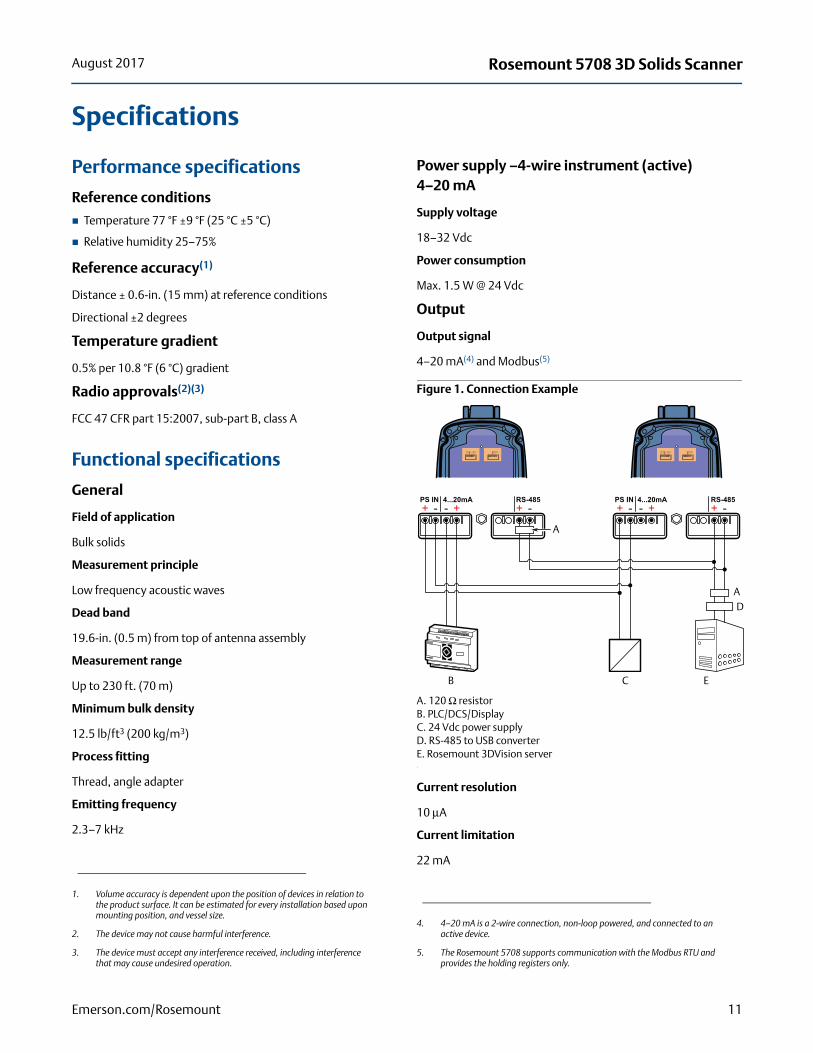
Specifications
Performance specifications
Reference conditions
Temperature 77 °F ±9 °F (25 °C ±5 °C)
Relative humidity 25–75%
Reference accuracy(1)
Distance ± 0.6-in. (15 mm) at reference conditions
Directional ±2 degrees
Temperature gradient
0.5% per 10.8 °F (6 °C) gradient
Radio approvals(2)(3)
FCC 47 CFR part 15:2007, sub-part B, class A
Functional specifications
General
Field of application
Bulk solids
Measurement principle
Low frequency acoustic waves
Dead band
19.6-in. (0.5 m) from top of antenna assembly
Measurement range
Up to 230 ft. (70 m)
Minimum bulk density
12.5 lb/ft3 (200 kg/m3)
Process fitting
Thread, angle adapter
Emitting frequency
2.3–7 kHz
Power supply –4-wire instrument (active)4–20 mA
Supply voltage
18–32 Vdc
Power consumption
Max. 1.5 W @ 24 Vdc
Output
Output signal
4–20 mA(4) and Modbus(5)
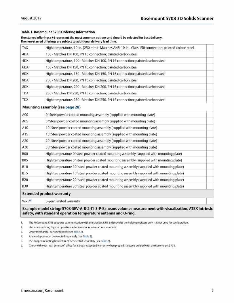
Figure 1. Connection Example
A. 120 Ω resistorB. PLC/DCS/DisplayC. 24 Vdc power supplyD. RS-485 to USB converterE. Rosemount 3DVision server
Current resolution
10 μA
Current limitation
22 mA
1. Volume accuracy is dependent upon the position of devices in relation to the product surface. It can be estimated for every installation based upon mounting position, and vessel size.
2. The device may not cause harmful interference.
3. The device must accept any interference received, including interference that may cause undesired operation.
4. 4–20 mA is a 2-wire connection, non-loop powered, and connected to an active device.
5. The Rosemount 5708 supports communication with the Modbus RTU and provides the holding registers only.
+ -PS OUT
Display
+ -PS OUT
Display
+ +- -PS IN 4...20mA
+ -RS-485 PS IN 4...20mA RS-485
+ +- - + -
+ +- -PS IN 4...20mA
+ -RS-485
+ +- -PS IN 4...20mA
+ -RS-485
A
A
ECB
D
11Emerson.com/Rosemount

Rosemount 5708 3D Solids Scanner August 2017
Maximum load (active output)
400 Ω
Communication
Physical
RS-485
Protocol
Modbus(1)
Process pressure, temperature, and humidity
Vessel pressure
–0.29... 43.5 PSI (–20 mBar... 3 Bar)
Process temperature measured on the process fitting
Standard temperature: –40... +185 F° (–40... +85 °C)
High temperature: –40... +356 °F (–40... +180 °C)
Process humidity
up to 75% RH
Ambient, storage, and transport temperature
–40... +185 °F (–40... +85 °C)
Ingress protection
IP66, IP67 according to IEC 60529
Display and configuration
Output units
Level and distance: feet (ft.), meters (m)
Volume: cubic meters (m3), cubic feet (ft3), liters, gallons, bushels
Mass: tons (US short), tons (metric), pounds (lb)
Bulk density: ton/m3, lbs/ft3, gr/cm3, kg/m3
Temperature: Fahrenheit (°F), Celsius (°C)
Output variables
Configuration tools
LCD display with four-button keypad(2)
Rosemount 3DVision software (for single site/vessel)
Rosemount 3DMultiVision software (for multiple sites/vessels)
Emerson Wireless THUM™ Adapter(3)
The THUM Adapter can be connected to the Rosemount 5708 by mounting it remotely using a remote mount kit.
See the Emerson Wireless THUM™ Adapter Product Data Sheet and Technical Note.
1. The Rosemount 5708 supports communication with the Modbus RTU and provides the holding registers only.
Rosemount5708L
Rosemount5708V
Rosemount5708S
Level/distance
Minimum and maximum level/distance
N/A
Volume N/A
Mass(1)
1. The mass is calculated in a conversion using one of the available methods within Rosemount 3DVision or independently on the customer's DCS/PLC/SCADA.
N/A
SNR
Temperature at antenna
2. The Rosemount 5708L can be completely configured via the LCD display. For the Rosemount 5708V and 5708S, the Rosemount 3DVision/3DMultiVision software is required.
3. The Rosemount 5708 with the THUM Adapter enables wireless access to the following parameters: 4–20mA current, distance, percentage, temperature and SNR. Diagnostics and configuration are available through wired connection.
12 Emerson.com/Rosemount

Rosemount 5708 3D Solids ScannerAugust 2017
Physical specifications
Material selection
Emerson provides a variety of Rosemount products with various product options and configurations including materials of construction that can be expected to perform well in a wide range of applications. The Rosemount product information presented is intended as a guide for the purchaser to make an appropriate selection for the application. It is the purchaser’s sole responsibility to make a careful analysis of all process parameters (such as all chemical components, temperature, pressure, flow rate, abrasives, contaminants, etc.), when specifying product, materials, options and components for the particular application. Emerson Process Management is not in a position to evaluate or guarantee the compatibility of the process material or other process parameters with the product, options, configuration or materials of construction selected.
Housing and enclosure
Housing
Painted aluminum die casting
Antenna
Painted aluminum die casting (optional PTFE coating available)
Display window in housing
Polycarbonate/PC-ABS
Electrical connection
M20 for cable glands or conduit entries
Recommended output cabling is low resistance, twisted shielded pairs, 20–24 AWG
Cable entry/plug
1 x M20 x1.5 (cable Ø 8 to 13 mm)
1 x plug M20x 1.5
2 optional thread adapters M20, 1/2-in. NPT
Process fitting
Requires mounting plate
Weight
12.35 lb (5.6 kg)
Vessel connection
Mounting plate(1)
Minimum distance from filling points
24-in. (600 mm)
Minimum distance from side wall
24-in. (600 mm)
Mounting plate dimensions
According to DIN PN16 or ANSI Class 150 size and holes pattern
Display panel
LCD display
4 lines x 20 characters
Adjustment elements
4 keys (ESC, +, –, E)
1. Mounting plates are available to accommodate 4–10-in. (100–250 mm) openings. For openings smaller than 8-in. (200 mm), there are antenna extensions available to allow the antenna to be installed from the inside of the vessel below the nozzle.
13Emerson.com/Rosemount
Rosemount 5708 3D Solids Scanner August 2017
Accessories
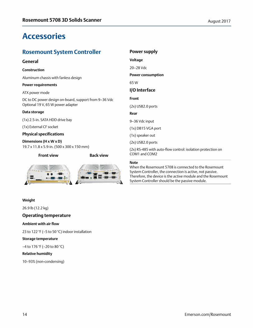
Rosemount System Controller
General
Construction
Aluminum chassis with fanless design
Power requirements
ATX power mode
DC to DC power design on-board, support from 9–36 VdcOptional 19 V, 65 W power adapter
Data storage
(1x) 2.5-in. SATA HDD drive bay
(1x) External CF socket
Physical specifications
Dimensions (H x W x D)19.7 x 11.8 x 5.9-in. (500 x 300 x 150 mm)
Weight
26.9 lb (12.2 kg)
Operating temperature
Ambient with air flow
23 to 122 °F (–5 to 50 °C) indoor installation
Storage temperature
–4 to 176 °F (–20 to 80 °C)
Relative humidity
10–93% (non-condensing)
Power supply
Voltage
20–28 Vdc
Power consumption
65 W
I/O Interface
Front
(2x) USB2.0 ports
Rear
9–36 Vdc input
(1x) DB15 VGA port
(1x) speaker out
(2x) USB2.0 ports
(2x) RS-485 with auto-flow control: isolation protection on COM1 and COM2
NoteWhen the Rosemount 5708 is connected to the Rosemount System Controller, the connection is active, not passive. Therefore, the device is the active module and the Rosemount System Controller should be the passive module.
Front view Back view
14 Emerson.com/Rosemount

Rosemount 5708 3D Solids ScannerAugust 2017
Rosemount LinkPro
Physical specifications
Housing enclosure
Polystyrene
Weight
3.13 lb (1.42 kg)
Dimensions (L x W x H)
10 x 7 x 3.5-in. (255 x 180 x 90 mm) - not including cable glands
Protection
IP66
Voltage supply
Operating voltage
10–30 Vdc (nominal 24 Vdc)
Average power consumption (idle mode)
1.5 W
Peak power consumption (transmit mode)
18 W
Power source limitation
2 A
Ambient temperature
–22 to +158 °F (–30 to +70 °C)
CE Conformity
EMC
Emission EN 301 489-7 V1.3.1:2005 standard harmonized under R&TTE Directive 1995/5/EC and EMC Directive 2004/108/EC Article 6(2)
Safety
EN 60950-1:06; EN 60950-22:06
Radio emissions
EN 301 511 V9.0.2
FCC Approval
FCC 47 CFR part:15:2007, subpart B, class A
Cable entry/plug
(2x) cable gland M20 x 1.5 (cable Ø 8–13 mm)
15Emerson.com/Rosemount

Rosemount 5708 3D Solids Scanner August 2017
Software Installation Requirements
Rosemount 3DVision server
Rosemount 3DVision client
Processor Intel™ Dual Core and above
RAM At least 1 GB
Hard disk At least 1 GB free space per year (2.8 MB per day for log files)
Graphic card resolution Minimum 1024 x 768
Interfaces Ethernet NIC card, serial port, USB port
Operating systems Microsoft® Windows™ XP (SP2), Windows 7, and Windows 10
Processor Intel Dual Core and above
RAM At least 1 GB
Hard disk At least 1 GB free space on HD
Graphic card resolution Minimum 1280 x 1024
Graphic card memory 1 GB
Interfaces Ethernet NIC card, CD-ROM drive or USB port
Operating systems Windows XP (SP2), Windows 7, and Windows 10
Framework Microsoft .NET framework 4.0
16 Emerson.com/Rosemount

Rosemount 5708 3D Solids ScannerAugust 2017
Product certificationsEuropean Directive Information
A copy of the EC Declaration of Conformity can be found at the end of the Rosemount 5708 Series Quick Start Guide. The most recent revision of the EC Declaration of Conformity can be found at EmersonProcess.com/Rosemount.
Ordinary Location Certification
As standard, the transmitter has been examined and tested to determine that the design meets the basic electrical, mechanical, and fire protection requirements by a nationally recognized test laboratory (NRTL) as accredited by the Federal Occupational Safety and Health Administration (OSHA).
North AmericaI5 US and Canada Intrinsic Safety (IS)
Certificate:3052166Standards: FM Class 3600–2011, FM Class 3610–2010,
FM Class 3810–2005, ANSI/IEC 60529–2004, CSA Std. C22.2. No. 25- 09, CSA Std. C22.2.No.157-92, CSA Std. C22.2 No. 1010–04,CAN/CSA E61241-1-1-2010
Markings: IS CL I, II DIV 1, GP C, D, E, F, G when connected per Rosemount drawing 05708-1900;T4(–40 °C < Ta < +85 °C); IP 6X
For electronic modules with serial number 836xxxxxxx:Supplies-Terminals J5.1 (+), J5.2 (GND)Vmax (Ui) = 30 V, Imax (Ii) = 212 mA, Pmax (Pi) = 1.2 W, Ci = 8 nF, Li = 0Interfaces-Terminals J5.4 (4 - 20 mA signal), J5.3 (GND common with J5.2):Vmax (Ui) = 10.5 V, Imax (Ii) = 106 mA, Pmax (Pi) = 1.1 W, Ci = 8 nF, Li = 0RS-485-Terminals J6.3 (P), J6.4 (N):Vmax (Ui) = 6.51 V, Imax (Ii) = 651 mA, Pmax (Pi) = 1.06 W, Ci = 0, Li = 0
Approval valid for HART® and Modbus options.
Special Conditions for Safe Use (X):
1. The 3D Solids Scanner is only for use with electronics unit marked with serial number 836xxxxxx, as these units are for use with the 3D Solids ambient temperature range.
2. Part of the enclosure is constructed of plastic. To prevent the risk of electrostatic sparking, the plastic surface should be cleaned with a damp cloth.
EuropeI1 ATEX Intrinsic Safety
Certificate: BVS14ATEXE060X
Standards: EN60079-0:2012, EN60079-11:2012
Markings: II 2 G Ex ib [ia] IIB T4 Gb (–40 °C < Ta < +85 °C)Ex II 1/2 D Ex ib [ia] IIIC T110°C Da/Db (–40 °C < Ta < +85 °C)
Table 4. Supply Circuit Parameters
Table 3. Interface Para<meters
Parameter 4–20 mA RS-485
Voltage Ui/Uo 10.5 V 6.51 V
Current Ii/Io 106 mA 2 x 651 mA
Power Pi/Po 1.1 W 2 x 1.06 W
Capacitance Ci 8 nF 0 nF
Inductance Li 0 mH 0 mH
Capacitance Co 16 μF 2 x 285 μF
Inductance Lo 80 μH 83.9 μH
Lo/Ro 17.77 μH/Ω 67.12 μH/Ω
Characteristics Trapezoid Linear
TerminalsJ5.3 (4–20 mA), J5.4 (GND)
J6.3 (+), J6.4 (RTN)
Parameter Input Output
Voltage Ui/Uo 24 V N/A
Current Ii Same values as the interconnected IS power supply
N/A
Power Pi/Po 3 W N/A
Capacitance Ci/Co 8 nF
Same values of the interconnected IS power supply reduced by Ci
Inductance Li/Lo 0 mH
Same values of the interconnected IS power supply reduced by Li
Lo /Ro ratio N/A
Same values of the interconnected IS power supply reduced by Li
Characteristics N/ASame values as the interconnected IS power supply
Terminals J5.1 (+), J5.2 (GND) N/A
17Emerson.com/Rosemount

Rosemount 5708 3D Solids Scanner August 2017
Special Condition for Safe Use (X):
1. Dust application:The installation of the 3D Solids Scanner or of the Antenna Unit of models providing head separation in the wall to areas requiring EPL Da (apparatus category 1D) equipment shall provide a degree of protection IP6X according to EN60529 and shall be carried out in such a way, that all metallic parts are integrated in the local equipotential bonding.Manufacturer’s technical information related to use of the 3D Solids Scanner in contact with aggressive/corrosive media and to avoid any risk of mechanical impact shall be observed.
InternationalI7 IECEx Intrinsic Safety
Certificate:IECEx BVS 15.0042XStandards: IEC 60079-0: 2011, IEC 60079-11: 2011Markings: Ex ib [ia] IIB T4 Gb (-40 °C < Ta < +85 °C)
Ex ib [ia] IIIC T110°C Da/Db (-40 °C < Ta < +85 °C)
Table 6. Supply Circuit Parameters
Special Condition for Safe Use (X):
1. Dust application:The installation of the 3D-Solids Scanner or of the Antenna Unit of models providing head separation in the wall to areas requiring EPL Da equipment shall provide a degree of protection IP6X according to IEC 60529 and shall be carried out in such a way, that all metallic parts are integrated in the local equipotential bonding. Manufacturer's technical information related to use of the 3D Solids Scanner in contact with aggressive/corrosive media and to avoid any risk of mechanical impact shall be observed.
BrazilI2 INMETRO Intrinsic Safety
Certificate:UL-BR 15.0072XStandards:ABNT NBR IEC 60079-0:2008 + Errata 1:2011,
ABNT NBR IEC 60079-11:2009
Markings: Ex ib [ia] IIB T4 Gb (- 40 °C < Ta < + 85 °C) Ex ib [ia] IIIC T110 °C Da/Db (- 40 °C < Ta < + 85 °C)
Table 5. Interface Parameters
Parameter 4–20 mA RS-485
Voltage Ui/Uo 10.5 V 6.51 V
Current Ii/Io 106 mA 2 x 651 mA
Power Pi/Po 1.1 W 2 x 1.06 W
Capacitance Ci 8 nF 0 nF
Inductance Li 0 mH 0 mH
Capacitance Co 16 μF 2 x 285 μF
Inductance Lo 80 μH 83.9 μH
Lo/Ro 17.77 μH/Ω 67.12 μH/Ω
Characteristics Trapezoid Linear
TerminalsJ5.3 (4–20 mA), J5.4 (GND)
J6.3 (+), J6.4 (RTN)
Parameter Input Output
Voltage Ui/Uo 26.6 V N/A
Current Ii Same values as the interconnected IS power supply
N/A
Power Pi/Po 3 W N/A
Capacitance Ci/Co
8 nF
Same values of the interconnected IS power supply reduced by Ci
Inductance Li/L0 0 mH
Same values of the interconnected IS power supply reduced by Li
Lo/Ro ratio N/A
Same values of the interconnected IS power supply reduced by Li
Characteristics N/ASame values as the interconnected IS power supply
Terminals J5.1 (+), J5.2 (GND) N/A
18 Emerson.com/Rosemount

Rosemount 5708 3D Solids ScannerAugust 2017
Table 8. Supply Circuit Parameters
Special Conditions for Safe Use (X):
1. The installation of the 3D Solids Scanner or of the Antenna Unit of models providing head separation in the wall to areas requiring EPL Da (Zone 20) equipment shall provide a degree of protection IP6X according to ABNT NBR IEC 60529 and shall be carried out in such a way, that all metallic parts are integrated in the local equipotential bonding.
2. Manufacturer's technical information related to use of the 3D Solids Scanner in contact with aggressive / corrosive media and to avoid any risk of mechanical impact shall be observed.
ChinaI3 China Intrinsic Safety
Certificate: GYJ14.1362XStandards: GB3836.1-2010, GB3836.4-2010,
IEC61241-0 - 2004, GB12476.4-2010Markings: Ex ib/ia IIB Gb T4 Ex ibD/iaD 21/20 T110 °C
Table 7. Interface Parameters
Parameter 4–20 mA RS-485
Voltage Ui/Uo 10.5 V 6.51 V
Current Ii/Io 106 mA 2 x 651 mA
Power Pi/Po 1.1 W 2 x 1.06 W
Capacitance Ci 8 nF 0 nF
Inductance Li 0 mH 0 mH
Capacitance Co 16 μF 2 x 285 μF
Inductance Lo 80 μH 83.9 μH
Lo/Ro 17.77 μH/Ω 67.12 μH/Ω
Characteristics Trapezoid Linear
TerminalsJ5.3 (4–20 mA), J5.4 (GND)
J6.3 (+), J6.4 (RTN)
Parameter Input Output
Voltage Ui/ Uo 24 V N/A
Current Ii Same values as the interconnected IS power supply
N/A
Power Pi/Po 3 W N/A
Capacitance Ci/Co 8 nF
Same values of the interconnected IS power supply reduced by Ci
Inductance Li/Lo 0 mH
Same values of the interconnected IS power supply reduced by Li
Lo / Ro ratio N/A
Same values of the interconnected IS power supply reduced by Li
Characteristics N/ASame values as the interconnected IS power supply
Terminals J5.1 (+), J5.2 (GND) N/A
Table 9. Interface Parameters
Parameter 4–20 mA RS-485
Voltage Ui/Uo 10.5 V 6.51 V
Current Ii/Io 106 mA 2 x 651 mA
Power Pi/Po 1.1 W 2 x 1.06 W
Capacitance Ci 8 nF 0 nF
Inductance Li 0 mH 0 mH
Capacitance Co 16 μF 2 x 285 μF
Inductance Lo 80 μH 83.9 μH
Lo/Ro 17.77 μH/Ω 67.12 μH/Ω
Characteristics Trapezoid Linear
TerminalsJ5.3 (4–20 mA), J5.4 (GND)
J6.3 (+), J6.4 (RTN)
19Emerson.com/Rosemount
Rosemount 5708 3D Solids Scanner August 2017
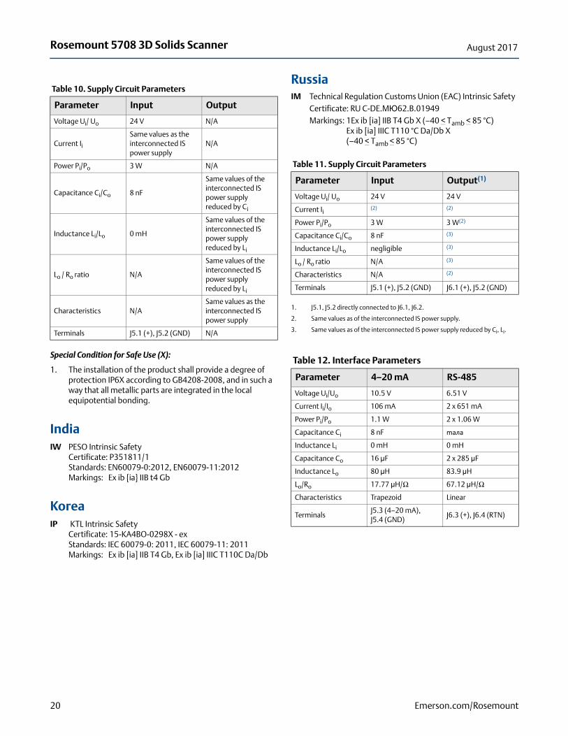
Special Condition for Safe Use (X):
1. The installation of the product shall provide a degree of protection IP6X according to GB4208-2008, and in such a way that all metallic parts are integrated in the local equipotential bonding.
IndiaIW PESO Intrinsic Safety
Certificate: P351811/1Standards: EN60079-0:2012, EN60079-11:2012Markings: Ex ib {ia} IIB t4 Gb
KoreaIP KTL Intrinsic Safety
Certificate: 15-KA4BO-0298X - exStandards: IEC 60079-0: 2011, IEC 60079-11: 2011Markings: Ex ib [ia] IIB T4 Gb, Ex ib [ia] IIIC T110C Da/Db
RussiaIM Technical Regulation Customs Union (EAC) Intrinsic Safety
Certificate: RU C-DE.MЮ62.B.01949Markings: 1Ex ib [ia] IIB T4 Gb X (–40 < Tamb < 85 °C)
Ex ib [ia] IIIC T110 °C Da/Db X (–40 < Tamb < 85 °C)
Table 10. Supply Circuit Parameters
Parameter Input Output
Voltage Ui/ Uo 24 V N/A
Current Ii Same values as the interconnected IS power supply
N/A
Power Pi/Po 3 W N/A
Capacitance Ci/Co 8 nF
Same values of the interconnected IS power supply reduced by Ci
Inductance Li/Lo 0 mH
Same values of the interconnected IS power supply reduced by Li
Lo / Ro ratio N/A
Same values of the interconnected IS power supply reduced by Li
Characteristics N/ASame values as the interconnected IS power supply
Terminals J5.1 (+), J5.2 (GND) N/A
Table 11. Supply Circuit Parameters
Parameter Input Output(1)
1. J5.1, J5.2 directly connected to J6.1, J6.2.
Voltage Ui/ Uo 24 V 24 V
Current Ii (2) (2)
Power Pi/Po 3 W 3 W(2)
2. Same values as of the interconnected IS power supply.
Capacitance Ci/Co 8 nF (3)
3. Same values as of the interconnected IS power supply reduced by Ci, Li.
Inductance Li/Lo negligible (3)
Lo / Ro ratio N/A (3)
Characteristics N/A (2)
Terminals J5.1 (+), J5.2 (GND) J6.1 (+), J5.2 (GND)
Table 12. Interface Parameters
Parameter 4–20 mA RS-485
Voltage Ui/Uo 10.5 V 6.51 V
Current Ii/Io 106 mA 2 x 651 mA
Power Pi/Po 1.1 W 2 x 1.06 W
Capacitance Ci 8 nF maлa
Inductance Li 0 mH 0 mH
Capacitance Co 16 μF 2 x 285 μF
Inductance Lo 80 μH 83.9 μH
Lo/Ro 17.77 μH/Ω 67.12 μH/Ω
Characteristics Trapezoid Linear
TerminalsJ5.3 (4–20 mA), J5.4 (GND)
J6.3 (+), J6.4 (RTN)
20 Emerson.com/Rosemount

Rosemount 5708 3D Solids ScannerAugust 2017
Special Conditions for Safe Use (X):
1. Levelmeter should be installed and operated in such a way that no danger of ignition due to electrostatic discharge.
2. The instructions specified in the manual, eliminates the risk of corrosion and / or mechanical action.
3. When the levelmeter, which provides separation of the head in areas requiring protection level equipment Da, the degree necessary to provide protection for at least IP6X in accordance with GOST 14254-96 and assembly should be performed so that all metal parts have the same potential.
Gas flow measurement by a Leading gas producer using Rosemount 1595 Conditioning Orifice Plate reduces operating and capital costs.
For detailed information on product certificates, refer to the Rosemount 5708 Reference Manual.
21Emerson.com/Rosemount

Rosemount 5708 3D Solids Scanner August 2017
Dimensional drawingsFigure 2. Rosemount 5708 with Antenna Assembly
Dimensions are in inches (millimeters).
Figure 3. Rosemount 5708 Housing
Dimensions are in inches (millimeters).
8.41 (213.5)
5.98 (152) 5.61 (142.5)
1.93- 8UN (49)
11.43(290.4)
11.28(286.5)
22.71 (576.8)
7.61 (193.3)
6.34 (161.1) 5.61 (142.5)
8.71 (221.2)
125°
22 Emerson.com/Rosemount

Rosemount 5708 3D Solids ScannerAugust 2017
Figure 4. Accessories - Neck Extension for Standard Temperature (Process Operating Temperature Code S)
Figure 5. Accessories - Neck Extension for High Temperature (Process Operating Temperature Code H)
X represents the available options.
X={12-in. (30 cm)20-in. (50 cm)39-in. (100 cm)79-in. (200 cm)118-in. (300 cm)
Ø 2.99 (76)
3.97 (101)
Ø 3.19 (81)
X={12-in. (30 cm)20-in. (50 cm)39-in. (100 cm)79-in. (200 cm)118-in. (300 cm)
3.97 (101)
23Emerson.com/Rosemount
Rosemount 5708 3D Solids Scanner August 2017
24 Emerson.com/Rosemount
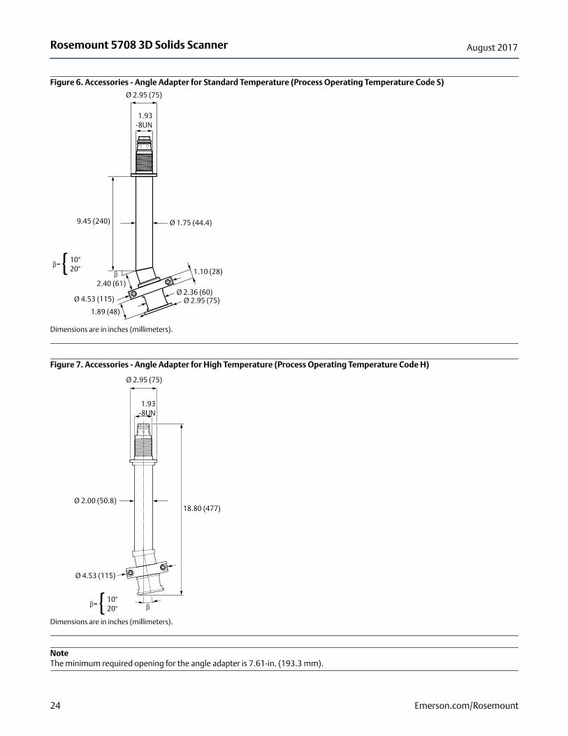
Figure 6. Accessories - Angle Adapter for Standard Temperature (Process Operating Temperature Code S)
Dimensions are in inches (millimeters).
Figure 7. Accessories - Angle Adapter for High Temperature (Process Operating Temperature Code H)
Dimensions are in inches (millimeters).
NoteThe minimum required opening for the angle adapter is 7.61-in. (193.3 mm).
β=10°20°{
Ø 1.75 (44.4)
1.10 (28)
Ø 2.95 (75)
1.93-8UN
9.45 (240)
Ø 2.95 (75)Ø 2.36 (60)
1.89 (48)
Ø 4.53 (115)
2.40 (61)β
Ø 2.95 (75)
1.93-8UN
18.80 (477)
ββ=10°20°{
Ø 2.00 (50.8)
Ø 4.53 (115)

Rosemount 5708 3D Solids ScannerAugust 2017
Figure 8. Accessories - Cable Extension
Dimensions are in inches (millimeters) if nothing else stated.
NoteX represents the available options. The cable extension and connector are available for standard temperature only.
Figure 9. Manhole Mounting Adapter
A. Installation adapterB. Set screw C. 2 mm hex key
Dimensions are in inches (millimeters).
Cable extension connector
Cable extension
X={12-in. (30 cm)20-in. (50 cm)39-in. (100 cm)79-in. (200 cm)118-in. (300 cm)
32 (82)
11 (3
0)
Sealing sleeves wraparound the cable andinserted into glands’internal sealing tubes.
A
B
C
ø 1.71 (44)
4.10 (104)
1x 3x 1x
25Emerson.com/Rosemount

Rosemount 5708 3D Solids Scanner August 2017
Figure 10. Accessories - ESP Hopper Mounting Adapter
A. Antenna adapterB. Support flangeC. Bracket flangeDimensions are in inches (millimeters).
NoteVertical nozzle for connecting to the bracket flange should be supplied by the customer.
9.84 (250)
35.43 (900)
Ø 1.67 (42.4)
20°
C
Ø 0.39 (10)Ø 0.39 (10)
Ø 9.76 (248)
Ø 10.83 (275)
Ø 1.73 (44)
6 x Ø 0.62 (15.8)equally spaced
A
B
B
26 Emerson.com/Rosemount

Rosemount 5708 3D Solids ScannerAugust 2017
Figure 11. Accessories - Mounting Plates
Dimensions are in inches (millimeters).
NoteSeveral different types of mounting plates are available. For detailed information, see the Rosemount 5708 Reference Manual. Mounting plates are not pressure rated.
DN200 (8DA, 8DX)
Ø13.38 (340)
12 x Ø 0.86 (22)equally spaced
Ø2.04 (52)
0.25 (6.4)
Ø11.61 (295)
DN250 (TDA, TDX)
Ø15.94 (405)
12 x Ø 1.02 (26)equally spaced
0.25 (6.4)
Ø2.04 (52)
Ø13.97 (355)
27Emerson.com/Rosemount

Rosemount 5708 3D Solids Scanner August 2017
Figure 12. Mounting Assembly
A. Mounting plateB. GasketC. Adapter tubeD. Adapter plateDimensions are in inches (millimeters).
Table 13. Mounting Assembly Option Codes for Different Angles
Angle A°Option code
standard temperatureOption code
high temperature
0 A00 B00
5 A05 B05
10 A10 B10
15 A15 B15
20 A20 B20
30 A30 B30
Ø 13.50 (342.9)
Ø 8.63 (219.1)
23.62 (600)
A°
0.32 (8.2)
3.54 (90)
10.17 (258.3)
28 Emerson.com/Rosemount

Rosemount 5708 3D Solids ScannerAugust 2017
29Emerson.com/Rosemount

Product Data SheetAugust 2017
Rosemount 5708 3D Solids Scanner00813-0100-4570, Rev CA
Global HeadquartersEmerson Automation Solutions6021 Innovation Blvd.Shakopee, MN 55379, USA
+1 800 999 9307 or +1 952 906 8888+1 952 949 7001 [email protected]
North America Regional OfficeEmerson Automation Solutions8200 Market Blvd.Chanhassen, MN 55317, USA
+1 800 999 9307 or +1 952 906 8888+1 952 949 7001 [email protected]
Latin America Regional OfficeEmerson Automation Solutions 1300 Concord Terrace, Suite 400Sunrise, FL 33323, USA
+1 954 846 5030+1 954 846 [email protected]
Europe Regional OfficeEmerson Automation Solutions Europe GmbHNeuhofstrasse 19a P.O. Box 1046CH 6340 BaarSwitzerland
+41 (0) 41 768 6111+41 (0) 41 768 6300 [email protected]
Asia Pacific Regional OfficeEmerson Automation Solutions Asia Pacific Pte Ltd1 Pandan CrescentSingapore 128461
+65 6777 8211+65 6777 0947 [email protected]
Middle East and Africa Regional OfficeEmerson Automation SolutionsEmerson FZE P.O. Box 17033Jebel Ali Free Zone - South 2Dubai, United Arab Emirates
+971 4 8118100+971 4 8865465 [email protected]
Linkedin.com/company/Emerson-Automation-Solutions
Twitter.com/Rosemount_News
Facebook.com/Rosemount
Youtube.com/user/RosemountMeasurement
Google.com/+RosemountMeasurement
Standard Terms and Conditions of Sale can be found on the Terms and Conditions of Sale page.The Emerson logo is a trademark and service mark of Emerson Electric Co.3DMultiVision, THUM, Rosemount and Rosemount logotype aretrademarks of Emerson.Modbus is a registered trademark of Modicon, Inc.HART is a registered trademark of FieldComm Group.Intel is a trademark of Intel Corporation in the U.S. and/or other countries.Microsoft is a registered trademark of Microsoft Corporation in the UnitedStates and other countries.Windows is a trademark of Microsoft Corporation in the United States andother countries.Rosemount and Rosemount logotype are trademarks of Emerson.All other marks are the property of their respective owners.© 2017 Emerson. All rights reserved.