Embed Size (px)
Citation preview
Safety Manual00809-0200-5100, Rev GC
October 2019
Rosemount™ 5900 Radar Level Gauge and Rosemount 2410 Tank HubSafety Manual for Use in Safety Instrumented Systems
Certified to relevant requirements of IEC 61508:2010 parts 1-7
This manual is valid for model code Safety Certification (SIS) option 2 and 3


Safety Manual 00809-0200-5100, Rev GC
Title PageOctober 2019
Rosemount™ Tank Gauging
NOTICE
Read this manual before working with the product. For personal and system safety, and for optimum product performance, make sure you thoroughly understand the contents before installing, using, or maintaining this product.
For equipment service or support needs, contact your local Emerson Process Management/Rosemount Tank Gauging representative.
Spare PartsAny substitution of non-recognized spare parts may jeopardize safety. Repair, e.g. substitution of components etc, may also jeopardize safety and is under no circumstances allowed.
Rosemount Tank Radar AB will not take any responsibility for faults, accidents, etc caused by non-recognized spare parts or any repair or modification which is not made by authorized representative.
NOTICE
Document No. changed from 300540EN to 00809-0200-5100.
The revision no. for this safety manual is included in the SIL certification although not explicitly stated in the SIL certificates.
iTitle Page

Safety Manual00809-0200-5100, Rev GC
Title PageOctober 2019
ii Title Page

Safety Manual 00809-0200-5100, Rev GC
ContentsOctober 2019
Table of Contents
1Section 1: Scope and Purpose of the Safety Manual
2Section 2: Reference Documents
3Section 3: Scope of the Product3.1 Purpose of the product . . . . . . . . . . . . . . . . . . . . . . . . . . . . . . . . . . . . . . . . . . . . . . . . . . 5
3.2 Certification. . . . . . . . . . . . . . . . . . . . . . . . . . . . . . . . . . . . . . . . . . . . . . . . . . . . . . . . . . . . 6
3.2.1 Assumptions and restrictions for the usage of the product . . . . . . . . . . . . . 6
3.2.2 Functional specification of the safety function . . . . . . . . . . . . . . . . . . . . . . . . 8
3.2.3 Maintenance . . . . . . . . . . . . . . . . . . . . . . . . . . . . . . . . . . . . . . . . . . . . . . . . . . . . . 9
4Section 4: Installation and Configuration4.1 Installation and commissioning. . . . . . . . . . . . . . . . . . . . . . . . . . . . . . . . . . . . . . . . . .11
4.1.1 Wiring diagram . . . . . . . . . . . . . . . . . . . . . . . . . . . . . . . . . . . . . . . . . . . . . . . . . .12
4.1.2 The Rosemount 5900 terminal block . . . . . . . . . . . . . . . . . . . . . . . . . . . . . . .14
4.1.3 Connecting the Rosemount 2410 to the 5900 . . . . . . . . . . . . . . . . . . . . . . .15
4.1.4 Rosemount 2410 relay output connection . . . . . . . . . . . . . . . . . . . . . . . . . .16
4.2 Safety alarm setup . . . . . . . . . . . . . . . . . . . . . . . . . . . . . . . . . . . . . . . . . . . . . . . . . . . . .19
4.2.1 Safety measurement performance . . . . . . . . . . . . . . . . . . . . . . . . . . . . . . . . .19
4.2.2 Safety alarm parameters and tank geometry . . . . . . . . . . . . . . . . . . . . . . . .20
4.2.3 Amplitude thresholds . . . . . . . . . . . . . . . . . . . . . . . . . . . . . . . . . . . . . . . . . . . .24
4.2.4 Setting the SIL High Alarm Limit . . . . . . . . . . . . . . . . . . . . . . . . . . . . . . . . . . .27
4.2.5 Setting the SIL Low Alarm Limit . . . . . . . . . . . . . . . . . . . . . . . . . . . . . . . . . . . .29
4.2.6 Safety alarm configuration . . . . . . . . . . . . . . . . . . . . . . . . . . . . . . . . . . . . . . . .30
4.2.7 How to filter out LPG Verification Pin or Reference Reflector. . . . . . . . . . .43
4.2.8 How to adjust the SIL Amplitude Threshold. . . . . . . . . . . . . . . . . . . . . . . . . .44
4.2.9 Changing the current alarm configuration . . . . . . . . . . . . . . . . . . . . . . . . . .45
4.2.10How to adjust the SIL Hold Off Distance. . . . . . . . . . . . . . . . . . . . . . . . . . . . .48
4.2.11How to enable SIL Low Alarm Limit . . . . . . . . . . . . . . . . . . . . . . . . . . . . . . . . .49
4.2.12How to disable SIL Low Alarm Limit. . . . . . . . . . . . . . . . . . . . . . . . . . . . . . . . .50
5Section 5: Proof Test5.1 Check of surface measurement and verification of the relay function. . . . . . . . .52
5.1.1 Check of surface measurement . . . . . . . . . . . . . . . . . . . . . . . . . . . . . . . . . . . .52
5.1.2 Verification of the relay function . . . . . . . . . . . . . . . . . . . . . . . . . . . . . . . . . . .53
iiiContents

Safety Manual00809-0200-5100, Rev GC
ContentsOctober 2019
5.2 System test . . . . . . . . . . . . . . . . . . . . . . . . . . . . . . . . . . . . . . . . . . . . . . . . . . . . . . . . . . .54
5.3 SIL High Alarm test. . . . . . . . . . . . . . . . . . . . . . . . . . . . . . . . . . . . . . . . . . . . . . . . . . . . .55
5.3.1 Viewing a SIL High Alarm Test report . . . . . . . . . . . . . . . . . . . . . . . . . . . . . . .60
6Section 6: Terms and Definitions
AAppendix A: Parameters Related to the Safety FunctionA.1 Rosemount™ 5900 and 2410 (SIL 2, 1-in-1). . . . . . . . . . . . . . . . . . . . . . . . . . . . . . . .65
A.2 Rosemount 5900 and 2410 (SIL 3, 2-IN-1) . . . . . . . . . . . . . . . . . . . . . . . . . . . . . . . .65
A.3 Rosemount 5900 and 2410 (SIL 2, 2-in-1) . . . . . . . . . . . . . . . . . . . . . . . . . . . . . . . . .66
A.4 Assumptions . . . . . . . . . . . . . . . . . . . . . . . . . . . . . . . . . . . . . . . . . . . . . . . . . . . . . . . . . .67
BAppendix B: Supported Antennas
CAppendix C: Safety System IdentificationC.1 Device Id . . . . . . . . . . . . . . . . . . . . . . . . . . . . . . . . . . . . . . . . . . . . . . . . . . . . . . . . . . . . .71
C.2 Baselines . . . . . . . . . . . . . . . . . . . . . . . . . . . . . . . . . . . . . . . . . . . . . . . . . . . . . . . . . . . . .72
C.3 SIL Level . . . . . . . . . . . . . . . . . . . . . . . . . . . . . . . . . . . . . . . . . . . . . . . . . . . . . . . . . . . . . .73
DAppendix D: SIL Measurement Status
EAppendix E: Disabling the SIL High Alarm
FAppendix F: Cone Pipe Antenna
GAppendix G: Dry-run Configuration
iv Contents

1
Safety Manual 00809-0200-5100, Rev GC
Scope and Purpose of the Safety ManualOctober 2019
Scope and Purpose of the Safety Manual
Section 1 Scope and Purpose of the Safety Manual
The purpose of the safety manual is to document all the information, relating to the Rosemount Tank Gauging system, which is required to enable integration into a safety-related system, in compliance with the requirements of IEC 61508.

2
Safety Manual00809-0200-5100, Rev GC
Scope and Purpose of the Safety ManualOctober 2019
Scope and Purpose of the Safety Manual

Safety Manual 00809-0200-5100, Rev GC
Reference DocumentsOctober 2019
Section 2 Reference Documents
IEC 61508
IEC 61511
Rosemount™ Tank Gauging System Configuration Manual (Ref. no. 00809-0300-5100)
Rosemount 2410 Tank Hub Reference Manual (Ref. no. 00809-0100-2410)
Rosemount 5900S Radar Level Gauge Reference Manual (Ref. no. 00809-0100-5900)
Rosemount 5900C Radar Level Gauge Reference Manual (Ref. no. 00809-0100-5901)
Rosemount Tank Gauging System Data Sheet (Ref. no. 00813-0100-5100.)
3Reference Documents
Safety Manual00809-0200-5100, Rev GC
Reference DocumentsOctober 2019
4 Reference Documents

Safety Manual 00809-0200-5100, Rev GC
Scope of the ProductOctober 2019
Section 3 Scope of the Product
3.1 Purpose of the product
The Rosemount™ Tank Gauging Safety System is designed for high performance level gauging in various types of storage tanks. It measures the distance to a liquid in a tank for Safety Instrumented Systems. The SIL Alarm Relay output is used for alarm indication of overfill and dry-run risk. Non safety-related instruments such as temperature sensors, remote display units, water level sensors, pressure sensors, and other instruments can be connected. The non-safety related instruments must not be used in Safety Instrumented Systems but can be connected independently to the same system without affecting the safety function.
The Rosemount Tank Gauging Safety System is intended for use as a level measurement sensor in safety instrumented functions (SIF) designed per IEC 61511. It is comprised of the following main elements:
Rosemount 5900
The Rosemount 5900 is a radar level gauge developed for a wide range of applications at bulk liquid storage facilities. Different antennas can be used in order to meet the requirements of different applications. The 2-in-1 version of the Rosemount 5900 has two independent and galvanically isolated radar modules in the same transmitter enclosure using a single antenna.
The Rosemount 5900 outputs an intrinsically safe SIL Alarm signal which is connected to the Rosemount 2410.
Rosemount 2410
The Rosemount 2410 acts as a power supply to the connected Rosemount 5900 using the intrinsically safe Tankbus. The Rosemount 2410 provides the SIL Alarm relay output and digital communication allowing connection of configuration tools or safety control system.
5Scope of the Product
Safety Manual00809-0200-5100, Rev GC
Scope of the ProductOctober 2019
3.2 Certification
The Rosemount Tank Gauging Safety System is designed for applications in high demand mode operation (demand rate of 1 per week).
The Rosemount Tank Gauging Safety System is certified to:
Low/High Demand of operation
Systematic Capability: SIL 3 capable
Random Capability for type B device: - 1 in 1 SIL2: SIL 3 @ HFT=1, SIL 2 @ HFT=0- 2 in 1 SIL2: SIL 3 @ HFT=1, SIL 2 @ HFT=0- 2 in 1 SIL3: SIL 3 @ HFT=0, SIL 2 @ HFT=0
3.2.1 Assumptions and restrictions for the usage of the product
Install the Rosemount Tank Gauging Safety System according to the instructions in this manual (Rosemount 5900 Radar Level Gauge and 2410 Tank Hub Safety Manual, Document No. 00809-0200-5100).
The following documents provide further instructions for a safe installation:
Rosemount Tank Gauging System Configuration Manual (Document No. 00809-0300-5100)
Rosemount 2410 Tank Hub Reference Manual (Document No. 00809-0100-2410)
Rosemount 5900S Radar Level Gauge Reference Manual (Document No. 00809-0100-5900)
Rosemount 5900C Radar Level Gauge Reference Manual (Document No. 00809-0100-5901)
NoteThe Rosemount 5900 Radar Level Gauge is not safety-rated during maintenance work, configuration changes, or other activity that affects the Safety Function. Alternative means should be used to ensure process safety during such activities.
It is important that the Rosemount Tank Gauging Safety System is installed and used in appropriate applications as described in relevant installation instructions. Otherwise the required functional safety may not be maintained.
The instruments in a Rosemount Tank Gauging System must be operated within specified environmental conditions. Operating conditions are available in the Rosemount Tank Gauging System Data Sheet, Document No. 00813-0100-5100.
If there are any echoes measured by the Rosemount 5900 which cannot be traced back to the product surface, note if there are any objects such as beams, heating coils etc. in the tank corresponding to the found echoes. Appropriate action has to be taken if the disturbing echoes affect measurement performed, please contact Emerson Process Management/Rosemount Tank Gauging for advice.
6 Scope of the Product

Safety Manual 00809-0200-5100, Rev GC
Scope of the ProductOctober 2019
Disturbing echoes within the radar beam from flat obstructions with a sharp edge may lead to a situation where the Rosemount Tank Gauging Safety System can no longer be used for safety related functions.
The Rosemount Tank Gauging Safety System is designed for a level rate of up to 50 mm (2 inches) per second.
In addition to the requirements mentioned above, the following constraints apply for the Rosemount Tank Gauging Safety System:
Turbulent product surface is not permitted
Foam on top of the product surface is not permitted
Solid products are not permitted
Level rate may not exceed 50 mm/s (2 in./s)
Still-pipe Array Antenna with hinged hatch
The Rosemount 5900 Radar Level Gauge including the SIL alarm output is not safety-rated during maintenance work. This includes opening of the Rosemount 5900 still-pipe array antenna, hinged hatch version during for example manual gauging (hand-dip) or product sampling.
During hatch opening, system will go to de-energized state (alarm). If needed, alternative means should be used to ensure process safety during opening of hatch.
7Scope of the Product

Safety Manual00809-0200-5100, Rev GC
Scope of the ProductOctober 2019
3.2.2 Functional specification of the safety function
The Rosemount Tank Gauging Safety System provides a SIL Alarm Relay output to indicate overfill or dry-run risk. No other output is related to the safety function.
The Rosemount Tank Gauging Safety System provides the following safety functions:
Measures the distance from the SIL Reference Point to the surface of a liquid in a tank
De-energizes (alarm) a safety critical output signal upon passing the configured SIL High or Low Alarm Limits, where these limits are defined as distances from the SIL Reference Point
The Rosemount Tank Gauging Safety System contains advanced self-diagnostics; internal monitoring features, and is programmed to go to de-energized state (alarm) upon detection of an internal failure.
Safety architecture
The Rosemount Tank Gauging Safety System offers various models in order to support different system configurations.
SIL 2 1-in-1 (1oo1D) Single channel architecture (1oo1D) complying with SIL 2. This version includes one
Rosemount 5900 Radar Level Gauge, one antenna, and one Rosemount 2410 Tank Hub.
SIL 2 2-in-1 (1oo1D) Single channel architecture (1oo1D) complying with SIL 2. This version includes one
“2-in-1” Rosemount 5900 Radar Level Gauge, one antenna, and one Rosemount 2410 Tank Hub.
SIL 3 2-in-1 (1oo2D) Dual channel architecture (internal 1oo2D) complying with SIL 3 - high reliability
version. Voting is performed in terminal block of Rosemount 5900 Radar level gauge. This version includes one “2-in-1” Rosemount 5900 Radar Level Gauge, one antenna, and one Rosemount 2410 Tank Hub.
In addition to the options described above, the customer can implement a system that complies with SIL 3 by having voting (1oo2D) performed in a safety logic solver. This version includes two Rosemount Tank Gauging Safety Systems with single channel architecture complying with SIL 2 (two Rosemount 5900 Radar Level Gauges, two antennas, and two Rosemount 2410 Tank Hubs).
8 Scope of the Product

Safety Manual 00809-0200-5100, Rev GC
Scope of the ProductOctober 2019
3.2.3 Maintenance
The proof test procedure should be carried out at regular intervals as described in Section 5: Proof Test.
Some applications may require periodic cleaning to ensure antenna contamination does not affect the measurement performance.
The devices in the Rosemount Tank Gauging Safety System may only be repaired or modified by authorized personnel trained by Emerson Process Management / Rosemount Tank Gauging.
For upgrade of firmware, use the procedure in the Rosemount 5900S Radar Level Gauge Reference Manual . Check release notes prior to upgrade, see the Rosemount Tank Gauging web site at Emerson.com.
9Scope of the Product

10
Safety Manual00809-0200-5100, Rev GC
Scope of the ProductOctober 2019
Scope of the Product
Safety Manual 00809-0200-5100, Rev GC
Installation and ConfigurationOctober 2019
Section 4 Installation and Configuration
4.1 Installation and commissioning
Before the actual safety configuration takes place, the Rosemount™ Tank Gauging Safety System shall be installed and configured as described in the following manuals:
Rosemount 2410 Tank Hub Reference Manual (Ref. no. 00809-0100-2410)
Rosemount 5900S Radar Level Gauge Reference Manual (Ref. no. 00809-0100-5900)
Rosemount 5900C Radar Level Gauge Reference Manual (Ref. no. 00809-0100-5901)
Rosemount Tank Gauging System Configuration Manual (Ref. no. 00809-0300-5100)
Rosemount Rosemount 5900 Proof Test Manual Supplement (Document No. 00809-0200-5900)
When the devices are up and running proceed with the Safety Alarm configuration as described in “Safety alarm setup” on page 19.
NoteInstallation drawings must be considered for installation of devices in a Rosemount Tank Gauging Safety System.
11Installation and Configuration

Safety Manual00809-0200-5100, Rev GC
Installation and ConfigurationOctober 2019
Cpfu
4.1.1 Wiring diagram
Figure 4-1. Wiring Diagram for Rosemount 2410 and Rosemount 5900 with SIL Option
See installation drawings as specified in Table 4-1 on page 13 for more information on wiring the Rosemount 2410 Tank Hub and the Rosemount 5900 Radar Level Gauge.
Rosemount 5900Radar Level Gauge
Rosemount 2410Tank Hub
SIL Alarm Relay Output
SIL Alarm
Tankbus
Intrinsically Safe (Exi)Non-Intrinsically Safe (Exd/Exe)
Power Supply
onfiguration (not art of the safety nction)
12 Installation and Configuration
Safety Manual 00809-0200-5100, Rev GC
Installation and ConfigurationOctober 2019
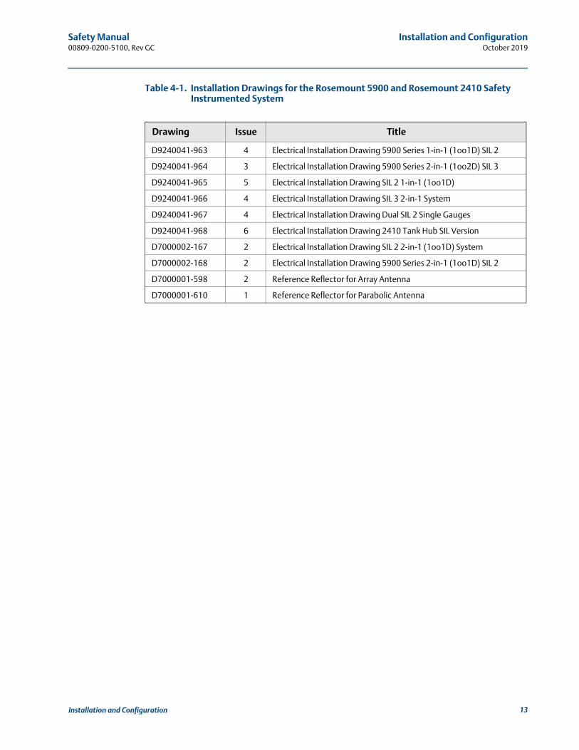
Table 4-1. Installation Drawings for the Rosemount 5900 and Rosemount 2410 Safety Instrumented System
Drawing Issue Title
D9240041-963 4 Electrical Installation Drawing 5900 Series 1-in-1 (1oo1D) SIL 2
D9240041-964 3 Electrical Installation Drawing 5900 Series 2-in-1 (1oo2D) SIL 3
D9240041-965 5 Electrical Installation Drawing SIL 2 1-in-1 (1oo1D)
D9240041-966 4 Electrical Installation Drawing SIL 3 2-in-1 System
D9240041-967 4 Electrical Installation Drawing Dual SIL 2 Single Gauges
D9240041-968 6 Electrical Installation Drawing 2410 Tank Hub SIL Version
D7000002-167 2 Electrical Installation Drawing SIL 2 2-in-1 (1oo1D) System
D7000002-168 2 Electrical Installation Drawing 5900 Series 2-in-1 (1oo1D) SIL 2
D7000001-598 2 Reference Reflector for Array Antenna
D7000001-610 1 Reference Reflector for Parabolic Antenna
13Installation and Configuration

Safety Manual00809-0200-5100, Rev GC
Installation and ConfigurationOctober 2019
4.1.2 The Rosemount 5900 terminal block
Terminal block connections for the Rosemount 5900 with SIL option:
Figure 4-2. Rosemount 5900 Terminal Compartment
Table 4-2. Rosemount 5900 Terminal Block Connections with SIL Alarm Output
See “Wiring diagram” on page 12 for information on how to connect a Rosemount 5900 Radar Level Gauge to a Rosemount 2410 Tank Hub in a Rosemount Tank Gauging Safety System.
Connection SIL Safety System
X1: Primary Tankbus in Intrinsically safe Tankbus input, power and communication
X2: Alarm SIL alarm output (connect to Exi terminal block on Rosemount 2410 Tank Hub)Note! There are different terminal blocks for SIL 2 and SIL 3.
X3: Primary Tankbus out Optional jumpers between X3 and X4 for connection to second level gauge when using the 2-in-1 version of the Rosemount 5900 for SIL 3 installations. No jumpers are used for SIL 2.X4: Secondary Tankbus in
Test terminals Test terminals for temporary connection of a handheld communicator such as the Rosemount 475 Field Communicator
Ground terminals, internal
SIL AlarmTankbus
Rosemount 5900 Radar Level Gauge
Test terminals
FB+
FB-
2-in-1: jumpers between X3 and X4 for connection to second level gauge
Label that indicates SIL Level SIL 3 or SIL 2
14 Installation and Configuration
Safety Manual 00809-0200-5100, Rev GC
Installation and ConfigurationOctober 2019
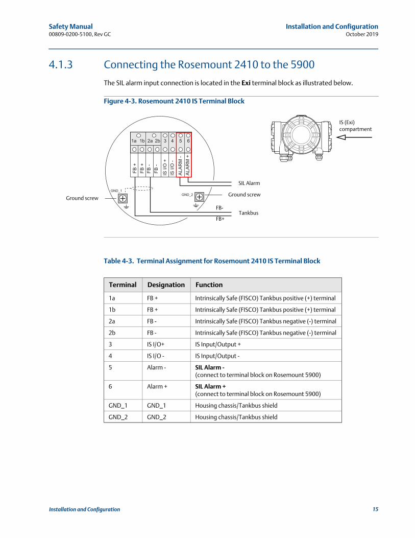
4.1.3 Connecting the Rosemount 2410 to the 5900
The SIL alarm input connection is located in the Exi terminal block as illustrated below.
Figure 4-3. Rosemount 2410 IS Terminal Block
Table 4-3. Terminal Assignment for Rosemount 2410 IS Terminal Block
Terminal Designation Function
1a FB + Intrinsically Safe (FISCO) Tankbus positive (+) terminal
1b FB + Intrinsically Safe (FISCO) Tankbus positive (+) terminal
2a FB - Intrinsically Safe (FISCO) Tankbus negative (-) terminal
2b FB - Intrinsically Safe (FISCO) Tankbus negative (-) terminal
3 IS I/O+ IS Input/Output +
4 IS I/O - IS Input/Output -
5 Alarm - SIL Alarm -(connect to terminal block on Rosemount 5900)
6 Alarm + SIL Alarm +(connect to terminal block on Rosemount 5900)
GND_1 GND_1 Housing chassis/Tankbus shield
GND_2 GND_2 Housing chassis/Tankbus shield
Ground screw
SIL Alarm
TankbusFB+
FB-
Ground screw
IS (Exi) compartment
15Installation and Configuration
Safety Manual00809-0200-5100, Rev GC
Installation and ConfigurationOctober 2019
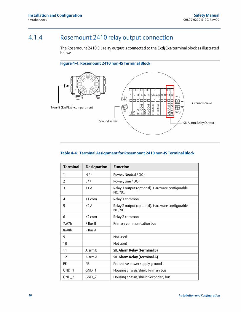
4.1.4 Rosemount 2410 relay output connection
The Rosemount 2410 SIL relay output is connected to the Exd/Exe terminal block as illustrated below.
Figure 4-4. Rosemount 2410 non-IS Terminal Block
Table 4-4. Terminal Assignment for Rosemount 2410 non-IS Terminal Block
Terminal Designation Function
1 N / - Power, Neutral / DC -
2 L / + Power, Line / DC +
3 K1 A Relay 1 output (optional). Hardware configurable NO/NC.
4 K1 com Relay 1 common
5 K2 A Relay 2 output (optional). Hardware configurable NO/NC.
6 K2 com Relay 2 common
7a/7b P Bus B Primary communication bus
8a/8b P Bus A
9 Not used
10 Not used
11 Alarm B SIL Alarm Relay (terminal B)
12 Alarm A SIL Alarm Relay (terminal A)
PE PE Protective power supply ground
GND_1 GND_1 Housing chassis/shield Primary bus
GND_2 GND_2 Housing chassis/shield Secondary bus
Ground screws
Ground screw SIL Alarm Relay Output
Non-IS (Exd/Exe) compartment
16 Installation and Configuration

Safety Manual 00809-0200-5100, Rev GC
Installation and ConfigurationOctober 2019
The basic principles of SIL alarm relay output for the Rosemount Tank Gauging Safety System is illustrated in Figure 4-5 on page 17 and Figure 4-6 on page 18. These illustrations show two configuration examples for a SIL 3 and a SIL 2 system, respectively.
Figure 4-5. SIL Alarm Relay Output for a Rosemount 5900 (2-in-1) Complying with SIL 3
+ -
Rosemount 2410 Rosemount 5900 (2-in-1)
SIL Alarm triggered by one or more of: SIL High/Low Alarm Internal error Not configured Not approved
Rosemount 2410Rosemount 5900 (2-in-1)
SIL Alarm Relay output to emergency shut-down system
SIL Alarm Relay output to emergency shut-down system
Tankbus
Tankbus
SIL Alarm
SIL Alarm
SIL Alarm Relay
SIL Alarm Relay
17Installation and Configuration

Safety Manual00809-0200-5100, Rev GC
Installation and ConfigurationOctober 2019
Figure 4-6. SIL Alarm Relay Output for a Rosemount 5900 (1-in-1) Complying with SIL 2
Rosemount 2410 Rosemount 5900 (2-in-1)Rosemount 2410
Rosemount 2410Rosemount 5900 (2-in-1)
SIL Alarm Relay output to emergency shut-down system
SIL Alarm Relay output to emergency shut-down system
Tankbus
Tankbus
SIL Alarm
SIL Alarm
SIL Alarm Relay
SIL Alarm Relay
SIL Alarm triggered by one or more of: SIL High/Low Alarm Internal error Not configured Not approved
18 Installation and Configuration

Safety Manual 00809-0200-5100, Rev GC
Installation and ConfigurationOctober 2019
4.2 Safety alarm setup
The Safety Alarm Setup procedure is used to set up the SIL Alarm Limits, the tank geometry, and to adjust the Rosemount 5900 Level Gauge for optimum measurement performance in the tank.
Prior to starting the Safety Alarm Setup, ensure that the actual distance to the product surface is known. This information is usually retrieved from the BPCS level sensor, or alternatively hand dipping can be performed.
Ensure that the product surface is calm and that the tank is not being emptied or filled during the safety alarm setup procedure.
4.2.1 Safety measurement performance
The Rosemount Tank Gauging Safety System has a safety accuracy better than ±0.5% of the measuring distance, or ±50 mm whichever is greater.
For Liquid Gas applications, the safety accuracy is reduced to about 4% of the measuring range. For Liquid Gas mixtures such as n-butane and propane, the safety accuracy is typically reduced to about 2% at the most. For estimation of the potential effect of other product mixtures, please contact your Emerson Process Management/Rosemount Tank Gauging representative.
Measuring range is from 1.2 m to 30 m (3.9 ft to 100 ft) below flange. For longer measuring range, please contact your Emerson Process Management/Rosemount Tank Gauging represen-tative.
19Installation and Configuration

Safety Manual00809-0200-5100, Rev GC
Installation and ConfigurationOctober 2019
4.2.2 Safety alarm parameters and tank geometry
Figure 4-7 to Figure 4-8 illustrate the tank geometry for a Rosemount 5900 with Parabolic Antenna and Array Antenna in a Rosemount Tank Gauging Safety System. Figure 4-9 and Figure 4-10 show the geometry with an optional Proof Test Reference Reflector.
Figure 4-7. Tank Geometry for Safety Alarm Configuration
Table 4-5. Safety Alarm Parameters
See “Safety alarm configuration” on page 30 for a description of how to configure the Rosemount Tank Gauging Safety System. See also Table 4-13 on page 36 for more information on safety alarm parameters.
Safety Alarm Parameter Description
SIL High Alarm Limit Product distance at which the Safety Alarm is triggered for overfill. See “Setting the SIL High Alarm Limit” on page 27.
SIL Low Alarm Limit Product distance at which the Safety Alarm is triggered for dry-run. Note that dry-run is not supported for LPG/LNG antennas. See “Setting the SIL Low Alarm Limit” on page 29.
SIL Hold Off Distance Adjustment This parameter can be used to increase the SIL Used Hold Off distance in order to filter out radar echoes from disturbing objects near the nozzle (see “How to adjust the SIL Hold Off Distance” on page 48 for more information).
SIL Used Hold Off Distance The SIL Hold Off Distance is typically used to filter out disturbances from a nozzle or any other object near the antenna. There is a default value for each antenna (Antenna Hold Off Distance) which can not be changed. The SIL Used Hold Off Distance is the sum of the Antenna Hold Off Distance and the SIL Hold Off Distance Adjustment.
SIL Reference Point
SIL High Alarm Limit
SIL Surface Distance
Measuring Range
SIL Hold Off Distance Adjustment
SIL Antenna Hold Off Distance
SIL Low Alarm Limit
SIL
Use
d H
old
Off
Dis
tanc
e
20 Installation and Configuration

Safety Manual 00809-0200-5100, Rev GC
Installation and ConfigurationOctober 2019
Figure 4-8. Tank Geometry for Safety Alarm Configuration of a Rosemount 5900 with LPG/LNG Antenna
SIL Reference Point
SIL High Alarm Limit
SIL Surface Distance
Measuring Range
SIL Used Hold Off Distance
SIL Hold Off Distance
> 500 mm
LPG Verification Pin
SIL Antenna Hold Off Distance
SIL LPG Pin Distance
21Installation and Configuration

Safety Manual00809-0200-5100, Rev GC
Installation and ConfigurationOctober 2019
Figure 4-9. Tank Geometry for a Rosemount 5900 with Parabolic Antenna and Proof Test Reference Reflector
For instructions on how to install and configure a Proof Test Reference Reflector, see the Rosemount 5900 Proof Test Manual Supplement (Document No. 00809-0200-5900).
The Reference Reflector Distance range depends on the reflector size as shown in Table 4-6.
Section “SIL High Alarm test” on page 55 provides a description of how to perform a SIL High Alarm test by using the Proof Test Reference Reflector.
Table 4-6. SIL Reference Reflector Distance
Reference Reflector Distance (mm) Diameter (mm)
600 RR Distance < 2000 250
2000 RR Distance < 3000 200
3000 RR Distance < 4000 135
4000 RR Distance < 5000 90
Proof Test Reference Reflector
Minimum 500 mm
SIL Reference Point
SIL High Alarm Limit
SIL Surface Distance
Measuring Range
SIL Low Alarm Limit
SIL
Use
d H
old
Off
Dis
tanc
e
SIL Reference Reflector Distance
22 Installation and Configuration
Safety Manual 00809-0200-5100, Rev GC
Installation and ConfigurationOctober 2019
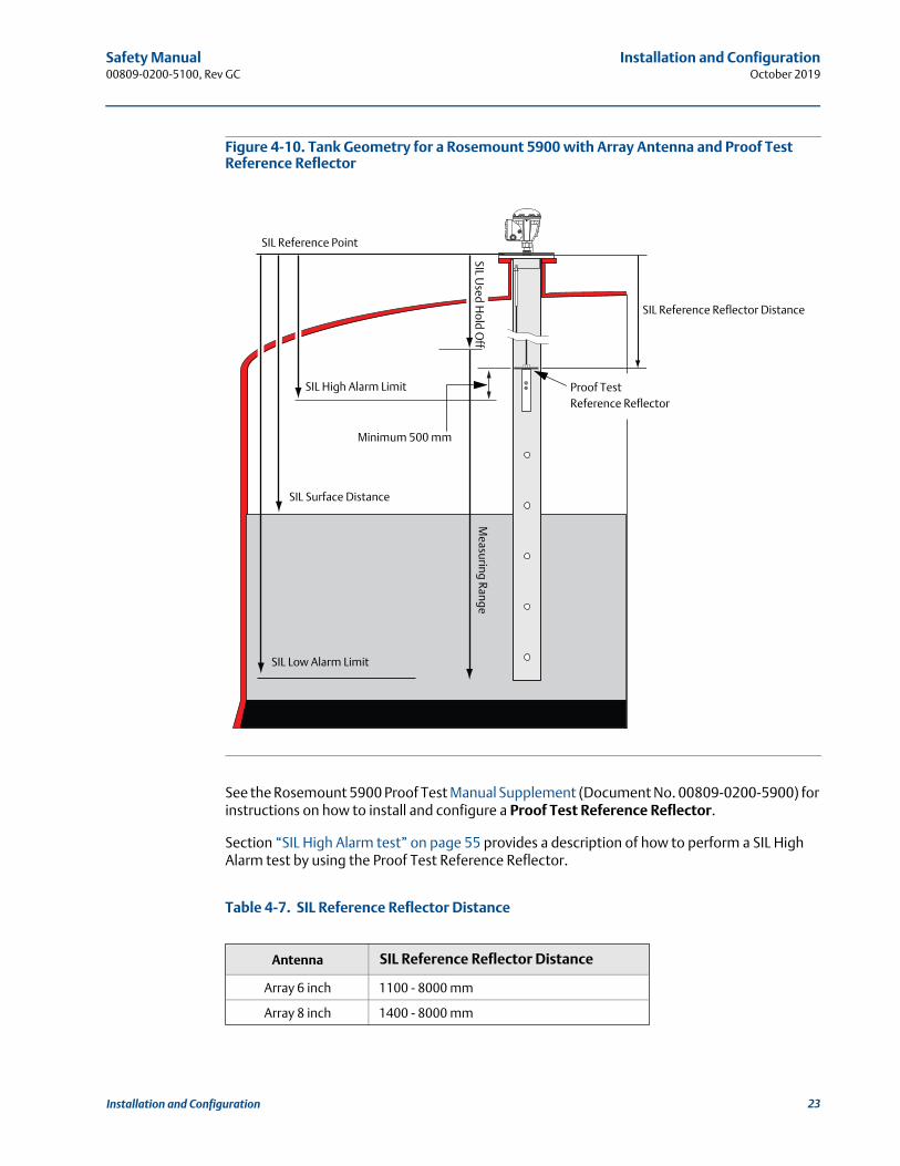
Figure 4-10. Tank Geometry for a Rosemount 5900 with Array Antenna and Proof Test Reference Reflector
See the Rosemount 5900 Proof Test Manual Supplement (Document No. 00809-0200-5900) for instructions on how to install and configure a Proof Test Reference Reflector.
Section “SIL High Alarm test” on page 55 provides a description of how to perform a SIL High Alarm test by using the Proof Test Reference Reflector.
Table 4-7. SIL Reference Reflector Distance
Antenna SIL Reference Reflector Distance
Array 6 inch 1100 - 8000 mm
Array 8 inch 1400 - 8000 mm
Minimum 500 mm
Proof Test Reference Reflector
SIL Reference Point
SIL High Alarm Limit
SIL Surface Distance
Measuring Range
SIL Low Alarm Limit
SIL Used H
old Off
SIL Reference Reflector Distance
23Installation and Configuration
Safety Manual00809-0200-5100, Rev GC
Installation and ConfigurationOctober 2019
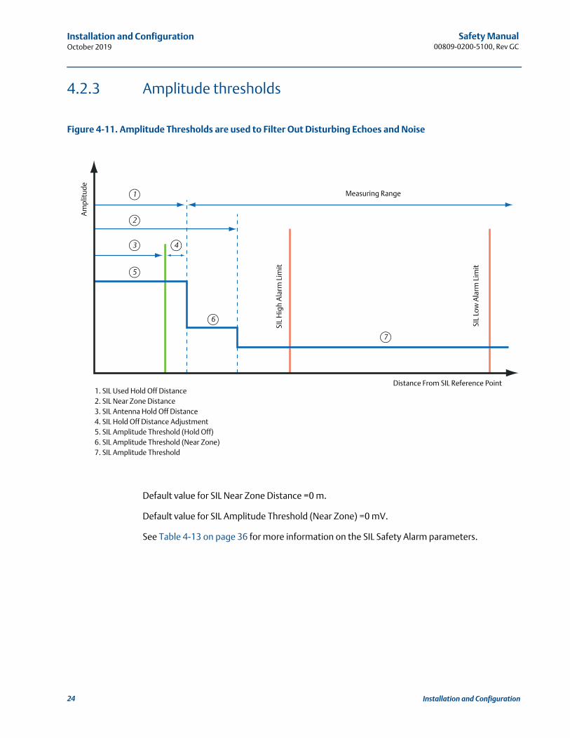
4.2.3 Amplitude thresholds
Figure 4-11. Amplitude Thresholds are used to Filter Out Disturbing Echoes and Noise
Default value for SIL Near Zone Distance =0 m.
Default value for SIL Amplitude Threshold (Near Zone) =0 mV.
See Table 4-13 on page 36 for more information on the SIL Safety Alarm parameters.
SIL
Hig
h A
larm
Lim
it
Measuring Range
Am
plit
ude
Distance From SIL Reference Point
SIL
Low
Ala
rm L
imit
1
4
2
3
6
7
5
1. SIL Used Hold Off Distance2. SIL Near Zone Distance3. SIL Antenna Hold Off Distance4. SIL Hold Off Distance Adjustment5. SIL Amplitude Threshold (Hold Off)6. SIL Amplitude Threshold (Near Zone)7. SIL Amplitude Threshold
24 Installation and Configuration
Safety Manual 00809-0200-5100, Rev GC
Installation and ConfigurationOctober 2019
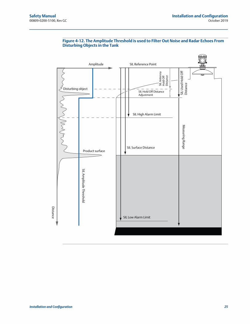
Figure 4-12. The Amplitude Threshold is used to Filter Out Noise and Radar Echoes From Disturbing Objects in the Tank
Amplitude
Distance
SIL Reference Point
SIL
Ant
enna
H
old
Off
D
ista
nce
SIL Hold Off Distance Adjustment
SIL High Alarm Limit
SIL Surface Distance
Measuring Range
SIL
Use
d H
old
Off
D
ista
nce
Disturbing object
Product surface
SIL Am
plitude Threshold
SIL Low Alarm Limit
25Installation and Configuration

Safety Manual00809-0200-5100, Rev GC
Installation and ConfigurationOctober 2019
Figure 4-13. Amplitude Threshold in Tank with Rosemount 5900 Radar Level Gauge and Reference Reflector
Amplitude
Distance
SIL Reference Point
SIL
Ant
enna
H
old
Off
D
ista
nce
SIL Hold Off Distance Adjustment
SIL High Alarm Limit
SIL Surface Distance
Measuring Range
SIL
Use
d H
old
Off
D
ista
nce
Disturbing object
Product surface
SIL Am
plitude Threshold
SIL Low Alarm Limit
Reference Reflector
Reference Reflector
26 Installation and Configuration

Safety Manual 00809-0200-5100, Rev GC
Installation and ConfigurationOctober 2019
4.2.4 Setting the SIL High Alarm Limit
The desired SIL High Alarm Limit needs to be adjusted for the expected product level rate. “Margin to add” in Table 4-8 is a safety margin to add to the desired SIL High Alarm Limit. This ensures that the reaction time of the Rosemount 5900 for different level rates is taken into account when specifying the desired SIL High Alarm Limit.
Table 4-8. Margin to Add to the Desired SIL High Alarm Limit for Various Level Rates
The “Minimum value for SIL High Alarm Limit” specifies how close to the SIL Reference Point that the High Alarm Limit may be set. Different figures apply depending on the level rate that may occur in the tank, see Table 4-9.
Table 4-9. Minimum Value for SIL High Alarm Limit
SIL Holdoff Distance Adjustment should be added to the figures in Table 4-9, see Figure 4-7 on page 20
If a LPG/LNG verification pin is installed in the Still-pipe, it must be placed > 500 mm above the SIL High Alarm Limit
See an example of how to configure the SIL High Alarm Limit in “Example” on page 28.
Margin to add (mm)
Level Rate
< 2 mm/s < 20 mm/s < 50 mm/s
120 380 980
Antenna Minimum value for SIL High Alarm Limit (mm)
Level Rate
< 2 mm/s < 20 mm/s < 50 mm/s
Horn 625 880 1480
Parabolic 625 680 1280
Array 5 inch 1125 1380 1980
Array 6 inch 1125 1380 1980
Array 8 inch 1425 1680 2280
Array 10 inch 1225 1480 2080
Array 12 inch 1525 1780 2380
LPG/LNG 725 980 1580
Cone 4 inch 425 680 1280
Cone 6 inch 525 780 1380
Cone 8 inch 625 880 1480
Cone Pipe 1” and 2” 225 460 1080
27Installation and Configuration

Safety Manual00809-0200-5100, Rev GC
Installation and ConfigurationOctober 2019
Example
Table 4-10. Example of how to Configure the SIL High Alarm Limit
The calculated SIL High Alarm Limit in this example is 2620 mm. This is well above 625 mm which is the minimum value that can be used for a Parabolic antenna at a maximum level rate of 2 mm/s as given by Table 4-9.
In case the SIL Hold Off Distance is adjusted, the SIL Hold Off Distance Adjustment value (see Table 4-13) must be added to the minimum value given by Table 4-9.
Antenna Parabolic
Desired SIL High Alarm Limit (as measured from the SIL Reference Point)
2500 mm
Maximum Level Rate that may occur in the tank 1.5 mm/s
Margin to add (Level Rate<2 mm/s) 120 mm
SIL High Alarm Limit to be configured in TankMaster 2500+120=2620 mm
28 Installation and Configuration

Safety Manual 00809-0200-5100, Rev GC
Installation and ConfigurationOctober 2019
4.2.5 Setting the SIL Low Alarm Limit
The desired SIL Low Alarm Limit needs to be adjusted for the expected product level rate. “Margin to subtract” in Table 4-11 is a safety margin to subtract from the desired SIL Low Alarm Limit. This ensures that the reaction time of the Rosemount 5900 for different level rates is taken into account when specifying the desired SIL Low Alarm Limit.
The minimum value specifies how close to the SIL Reference Point that the SIL Low Alarm Limit may be set, which is SIL High Alarm Limit + 500 mm.
Table 4-11. Margin to Subtract from the Desired SIL Low Alarm Limit for Various Level Rates
The “Maximum value for SIL Low Alarm Limit” specifies how far away from the SIL Reference Point that the SIL Low Alarm Limit may be set. Different figures apply depending on the application, see Table 4-12.
Table 4-12. Maximum Value for SIL Low Alarm Limit
Example
Desired SIL Low Alarm Limit for a 10 m high tank measuring in a still-pipe is 8500 mm. If maximum level rate is <1.5 mm/s, then the SIL Low Alarm Limit which will be entered in TankMaster in the Change Safety Alarm Parameters window is 8500 - 140 = 8360. This is well below 8860 mm (10000-1140) which is the maximum value that can be used for a still-pipe at a maximum level rate of 2 mm/s as given by Table 4-12.
Margin to subtract (mm)
Level Rate
< 2 mm/s < 20 mm/s < 50 mm/s
140 500 1100
Application Maximum value for SIL Low Alarm Limit (mm)
Level Rate
< 2 mm/s < 20 mm/s < 50 mm/s
If a water interface or a strong disturbance echo(1) is present or a still pipe is used
(1) A strong disturbance echo is more than 4 times stronger than the surface amplitude.Typical examples include the bottom echo of a flat tank floor. A medium disturbance echo is one that is less than 4 times the surface, yet too strong to be handled as background noise. Typical examples include heating coils etc.
The distance to a point 1140 mm above the echo
The distance to a point 1500 mm above the echo
The distance to a point 2100 mm above the echo
If an inclination plate or medium disturbance echo* is present
The distance to a point 640 mm above the echo
The distance to a point 1000 mm above the echo
The distance to a point 1600 mm above the echo
If a non-flat bottom is present (for parabolic or horn antennas)
Consult factory Consult factory Consult factory
29Installation and Configuration
Safety Manual00809-0200-5100, Rev GC
Installation and ConfigurationOctober 2019
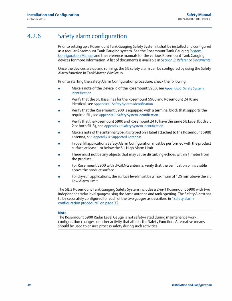
4.2.6 Safety alarm configuration
Prior to setting up a Rosemount Tank Gauging Safety System it shall be installed and configured as a regular Rosemount Tank Gauging system. See the Rosemount Tank Gauging System Configuration Manual and the reference manuals for the various Rosemount Tank Gauging devices for more information. A list of documents is available in Section 2: Reference Documents.
Once the devices are up and running, the SIL safety alarm can be configured by using the Safety Alarm function in TankMaster WinSetup.
Prior to starting the Safety Alarm Configuration procedure, check the following:
Make a note of the Device Id of the Rosemount 5900, see Appendix C: Safety System Identification
Verify that the SIL Baselines for the Rosemount 5900 and Rosemount 2410 are identical, see Appendix C: Safety System Identification
Verify that the Rosemount 5900 is equipped with a terminal block that supports the required SIL, see Appendix C: Safety System Identification
Verify that the Rosemount 5900 and Rosemount 2410 have the same SIL Level (both SIL 2 or both SIL 3), see Appendix C: Safety System Identification
Make a note of the antenna type, it is typed on a label attached to the Rosemount 5900 antenna, see Appendix B: Supported Antennas
In overfill applications Safety Alarm Configuration must be performed with the product surface at least 1 m below the SIL High Alarm Limit
There must not be any objects that may cause disturbing echoes within 1 meter from the product.
For Rosemount 5900 with LPG/LNG antenna, verify that the verification pin is visible above the product surface
For dry-run applications, the surface level must be a maximum of 125 mm above the SIL Low Alarm Limit
The SIL 3 Rosemount Tank Gauging Safety System includes a 2-in-1 Rosemount 5900 with two independent radar level gauges using the same antenna and tank opening. The Safety Alarm has to be separately configured for each of the two gauges as described in “Safety alarm configuration procedure” on page 32.
NoteThe Rosemount 5900 Radar Level Gauge is not safety-rated during maintenance work, configuration changes, or other activity that affects the Safety Function. Alternative means should be used to ensure process safety during such activities.
30 Installation and Configuration

Safety Manual 00809-0200-5100, Rev GC
Installation and ConfigurationOctober 2019
A brief overview of the setup procedure for the Rosemount Tank Gauging Safety System is illustrated in Figure 4-14:
Figure 4-14. Setup Procedure for the Rosemount Tank Gauging Safety System
STEP 1DEVICE VERIFICATION
Verify that correct equipment is installed and configured and that the surface level is at least 1 meter below the SIL High Alarm Limit. For dry-run applications the surface must be a maximum of 125 mm above the SIL Low Alarm Limit.
STEP 2CALIBRATION OF SURFACE
Adjust the SIL Amplitude Threshold until the Rosemount 5900 gauge finds the product surface.If needed, use the SIL Calibration Distance for minor adjustments to match actual distance to product surface with measured distance.
LPG/LNG only: reset filtering of Verification Pin.
LPG/LNG only: filter out the Verification Pin.
STEP 3FINAL ADJUSTMENT OF AMPLITUDE THRESHOLD
Adjust SIL Amplitude Threshold to increase Signal/Noise ratio.
STEP 4VERIFICATION OF SAFETY ALARM PARAMETERS
Verify that all safety parameters are correct before approving the Rosemount Tank Gauging Safety System.
STEP 5MAKE A BACKUP COPY
Make a backup copy of the gauge configuration database (use the TankMaster WinSetup “Save Database to File” option to store Holding and Input Registers).
31Installation and Configuration

Safety Manual00809-0200-5100, Rev GC
Installation and ConfigurationOctober 2019
Safety alarm configuration procedure
This section describes how to configure the Rosemount Tank Gauging Safety Alarm. For a SIL 3 system including a 2-in-1 Rosemount 5900 gauge, this procedure has to be performed for the primary and the secondary gauge, respectively.
To configure the Safety Alarm do the following:
1. Start the TankMaster WinSetup configuration program. Ensure that you are logged on to TankMaster as Administrator.
2. In the WinSetup workspace, click the right mouse button on the icon for the Rosemount 5900 Radar Level Gauge:
3. Choose the Properties option. The 5900 RLG Properties window appears.
4. Select the Advanced Configuration tab.
Properties
32 Installation and Configuration

Safety Manual 00809-0200-5100, Rev GC
Installation and ConfigurationOctober 2019
5. Click the Safety Alarm button to open the Safety Alarm window.
Safety Alarm
33Installation and Configuration

Safety Manual00809-0200-5100, Rev GC
Installation and ConfigurationOctober 2019
Step 1 Device verification
1. In the Device Information pane check that the Device Id is identical to the Device Id on the main label attached to the Rosemount 5900 housing. For a Rosemount 5900 2-in-1 version, the Device Id is divided in two parts. The first part is for the Primary device and the second for the Secondary device as described in Appendix C: Safety System Identification.
2. In the Device Information pane check the Device Id Checksum.Device Id Checksum = Device Id+ SIL Manipulated Device Id. The Device Id Checksum must be equal to x9999 (in case of five digit Device Id), where x is equal to the figure in the corresponding position of the Device Id.
Example: Device Id=10010. SIL Manipulated Device Id=9989.Device Id Checksum=10010+9989=19999.
3. Verify that Device Type=5900 RLG and Device Type No.=23.
4. Make a note of the SIL Write Config Counter. This figure is used for verifying that the level gauge properly reads and writes safety alarm parameters.
5. In the Device Information pane verify that the correct SIL Software version is used, see Appendix C: Safety System Identification.
34 Installation and Configuration

Safety Manual 00809-0200-5100, Rev GC
Installation and ConfigurationOctober 2019
Step 2 Calibration of surface
1. To configure the Safety Alarm parameters of the Rosemount 5900 gauge, click the Change Parameters button to open the Change Safety Alarm Parameters window.
2. In the Change Safety Alarm Parameters window, configure the Safety Alarm Parameters as described in Table 4-13 on page 36 (see also “Safety alarm parameters and tank geometry” on page 20).
35Installation and Configuration
Safety Manual00809-0200-5100, Rev GC
Installation and ConfigurationOctober 2019
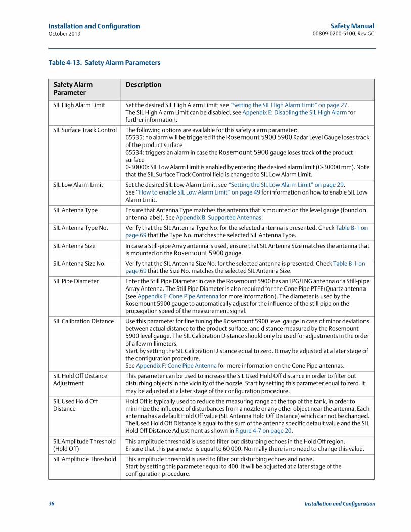
Table 4-13. Safety Alarm Parameters
Safety Alarm Parameter
Description
SIL High Alarm Limit Set the desired SIL High Alarm Limit; see “Setting the SIL High Alarm Limit” on page 27. The SIL High Alarm Limit can be disabled, see Appendix E: Disabling the SIL High Alarm for further information.
SIL Surface Track Control The following options are available for this safety alarm parameter:65535: no alarm will be triggered if the Rosemount 5900 5900 Radar Level Gauge loses track of the product surface65534: triggers an alarm in case the Rosemount 5900 gauge loses track of the product surface0-30000: SIL Low Alarm Limit is enabled by entering the desired alarm limit (0-30000 mm). Note that the SIL Surface Track Control field is changed to SIL Low Alarm Limit.
SIL Low Alarm Limit Set the desired SIL Low Alarm Limit; see “Setting the SIL Low Alarm Limit” on page 29.See “How to enable SIL Low Alarm Limit” on page 49 for information on how to enable SIL Low Alarm Limit.
SIL Antenna Type Ensure that Antenna Type matches the antenna that is mounted on the level gauge (found on antenna label). See Appendix B: Supported Antennas.
SIL Antenna Type No. Verify that the SIL Antenna Type No. for the selected antenna is presented. Check Table B-1 on page 69 that the Type No. matches the selected SIL Antenna Type.
SIL Antenna Size In case a Still-pipe Array antenna is used, ensure that SIL Antenna Size matches the antenna that is mounted on the Rosemount 5900 gauge.
SIL Antenna Size No. Verify that the SIL Antenna Size No. for the selected antenna is presented. Check Table B-1 on page 69 that the Size No. matches the selected SIL Antenna Size.
SIL Pipe Diameter Enter the Still Pipe Diameter in case the Rosemount 5900 has an LPG/LNG antenna or a Still-pipe Array Antenna. The Still Pipe Diameter is also required for the Cone Pipe PTFE/Quartz antenna (see Appendix F: Cone Pipe Antenna for more information). The diameter is used by the Rosemount 5900 gauge to automatically adjust for the influence of the still pipe on the propagation speed of the measurement signal.
SIL Calibration Distance Use this parameter for fine tuning the Rosemount 5900 level gauge in case of minor deviations between actual distance to the product surface, and distance measured by the Rosemount 5900 level gauge. The SIL Calibration Distance should only be used for adjustments in the order of a few millimeters.Start by setting the SIL Calibration Distance equal to zero. It may be adjusted at a later stage of the configuration procedure. See Appendix F: Cone Pipe Antenna for more information on the Cone Pipe antennas.
SIL Hold Off Distance Adjustment
This parameter can be used to increase the SIL Used Hold Off distance in order to filter out disturbing objects in the vicinity of the nozzle. Start by setting this parameter equal to zero. It may be adjusted at a later stage of the configuration procedure.
SIL Used Hold Off Distance
Hold Off is typically used to reduce the measuring range at the top of the tank, in order to minimize the influence of disturbances from a nozzle or any other object near the antenna. Each antenna has a default Hold Off value (SIL Antenna Hold Off Distance) which can not be changed. The Used Hold Off Distance is equal to the sum of the antenna specific default value and the SIL Hold Off Distance Adjustment as shown in Figure 4-7 on page 20.
SIL Amplitude Threshold (Hold Off)
This amplitude threshold is used to filter out disturbing echoes in the Hold Off region.Ensure that this parameter is equal to 60 000. Normally there is no need to change this value.
SIL Amplitude Threshold This amplitude threshold is used to filter out disturbing echoes and noise.Start by setting this parameter equal to 400. It will be adjusted at a later stage of the configuration procedure.
36 Installation and Configuration
Safety Manual 00809-0200-5100, Rev GC
Installation and ConfigurationOctober 2019
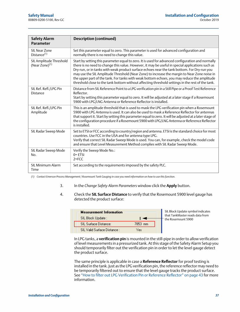
3. In the Change Safety Alarm Parameters window click the Apply button.
4. Check the SIL Surface Distance to verify that the Rosemount 5900 level gauge has detected the product surface:
In LPG tanks, a verification pin is mounted in the still-pipe in order to allow verification of level measurements in a pressurized tank. At this stage of the Safety Alarm Setup you should temporarily filter out the verification pin in order to let the level gauge detect the product surface.
The same principle is applicable in case a Reference Reflector for proof testing is installed in the tank. Just as the LPG verification pin, the reference reflector may need to be temporarily filtered out to ensure that the level gauge tracks the product surface. See “How to filter out LPG Verification Pin or Reference Reflector” on page 43 for more information.
SIL Near Zone Distance(1)
Set this parameter equal to zero. This parameter is used for advanced configuration and normally there is no need to change this value.
SIL Amplitude Threshold (Near Zone)(1)
Start by setting this parameter equal to zero. It is used for advanced configuration and normally there is no need to change this value. However, it may be useful in special applications such as Dry-run, or in tanks with weak product surface echoes near the tank bottom. For Dry-run you may use the SIL Amplitude Threshold (Near Zone) to increase the margin to Near Zone noise in the upper part of the tank. For tanks with weak bottom echoes, you may reduce the amplitude threshold close to the tank bottom without affecting threshold settings in the rest of the tank.
SIL Ref. Refl./LPG Pin Distance
Distance from SIL Reference Point to a LPG verification pin in a Still Pipe or a Proof Test Reference Reflector.Start by setting this parameter equal to zero. It will be adjusted at a later stage if a Rosemount 5900 with LPG/LNG Antenna or Reference Reflector is installed.
SIL Ref. Refl./LPG Pin Amplitude
This is an amplitude threshold that is used to mask the LPG verification pin when a Rosemount 5900 with LPG Antenna is used. It can also be used to mask a Reference Reflector for antennas that support it. Start by setting this parameter equal to zero. It will be adjusted at a later stage of the configuration procedure if a Rosemount 5900 with LPG/LNG Antenna or Reference Reflector is installed.
SIL Radar Sweep Mode Set to ETSI or FCC according to country/region and antenna. ETSI is the standard choice for most countries. Use FCC in the USA and for antenna type LPG. Verify that correct SIL Radar Sweep Mode is used. You can, for example, check the model code and ensure that Level Measurement Method complies with SIL Radar Sweep Mode.
SIL Radar Sweep Mode No.
Verify the Sweep Mode No.:0= ETSI2=FCC
SIL Minimum Alarm Time
Set according to the requirements imposed by the safety PLC.
(1) Contact Emerson Process Management / Rosemount Tank Gauging in case you need information on how to use this function.
Safety Alarm Parameter
Description (continued)
SIL Block Update symbol indicates that TankMaster reads data from the Rosemount 5900
37Installation and Configuration

Safety Manual00809-0200-5100, Rev GC
Installation and ConfigurationOctober 2019
5. If the SIL Surface Distance deviates significantly from the distance to the actual product surface, the gauge has probably locked on a disturbing object. Then you will have to filter out the disturbing echo by adjusting the SIL Amplitude Threshold to ensure that the Rosemount 5900 can detect the product surface as described in “How to adjust the SIL Amplitude Threshold” on page 44.
6. Once the Rosemount 5900 has detected the product surface, you may need to make minor adjustments of the SIL Calibration Distance in order to accurately match the SIL Surface Distance (measured by the Rosemount 5900) with the actual distance to the product surface. A positive SIL Calibration Distance will decrease the SIL Surface Distance. A negative SIL Calibration Distance increases the SIL Surface Distance.
7. In case the Rosemount Tank Gauging Safety System is configured for a Rosemount 5900 with LPG/LNG antenna, or a Reference Reflector for proof testing, you have to adjust the SIL Ref. Refl./LPG Pin Distance and the SIL Ref. Refl./LPG Pin Amplitude before proceeding with Step 3 “Final adjustment of amplitude thresholds” on page 39.
a. Reset the SIL Ref. Refl./LPG Pin Distance and the SIL Ref. Refl./LPG Pin Amplitude to zero.
b. Now the level gauge will detect the verification pin and present it as the product surface or as a Margin Echo.
c. Note the SIL Surface Distance (or the SIL Margin Echo Distance) and type it into the SIL Ref. Refl./LPG Pin Distance field.
d. Set the SIL Ref. Refl./LPG Pin Amplitude = 3 x SIL Surface Amplitude (or 3 x SIL Margin Echo Amplitude).
e. Verify that the levle gauge has found the actual product surface.
f. Proceed with Step 3 Final adjustment of amplitude thresholds.
c
d
x3
38 Installation and Configuration
Safety Manual 00809-0200-5100, Rev GC
Installation and ConfigurationOctober 2019
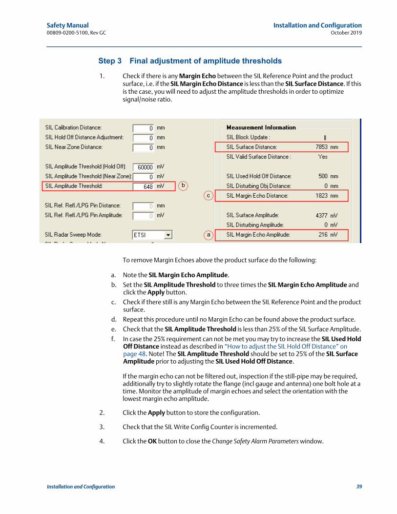
Step 3 Final adjustment of amplitude thresholds
1. Check if there is any Margin Echo between the SIL Reference Point and the product surface, i.e. if the SIL Margin Echo Distance is less than the SIL Surface Distance. If this is the case, you will need to adjust the amplitude thresholds in order to optimize signal/noise ratio.
To remove Margin Echoes above the product surface do the following:
a. Note the SIL Margin Echo Amplitude.
b. Set the SIL Amplitude Threshold to three times the SIL Margin Echo Amplitude and click the Apply button.
c. Check if there still is any Margin Echo between the SIL Reference Point and the product surface.
d. Repeat this procedure until no Margin Echo can be found above the product surface.
e. Check that the SIL Amplitude Threshold is less than 25% of the SIL Surface Amplitude.
f. In case the 25% requirement can not be met you may try to increase the SIL Used Hold Off Distance instead as described in “How to adjust the SIL Hold Off Distance” on page 48. Note! The SIL Amplitude Threshold should be set to 25% of the SIL Surface Amplitude prior to adjusting the SIL Used Hold Off Distance.
If the margin echo can not be filtered out, inspection if the still-pipe may be required, additionally try to slightly rotate the flange (incl gauge and antenna) one bolt hole at a time. Monitor the amplitude of margin echoes and select the orientation with the lowest margin echo amplitude.
2. Click the Apply button to store the configuration.
3. Check that the SIL Write Config Counter is incremented.
4. Click the OK button to close the Change Safety Alarm Parameters window.
a
b
c
39Installation and Configuration

Safety Manual00809-0200-5100, Rev GC
Installation and ConfigurationOctober 2019
Step 4 Verify safety alarm parameters
1. In the Safety Alarm window click the Change Safety Mode button to open the Change Safety Alarm Mode window:
2. Verify that identical Safety Alarm Parameter values appear in the Value and Read Back columns.
3. Verify the Rosemount 5900 Safety Alarm parameters:
SIL Verification Constant 1=”43210”
SIL Verification Constant 2=”56789”
40 Installation and Configuration
Safety Manual 00809-0200-5100, Rev GC
Installation and ConfigurationOctober 2019
4. Perform a final verification of the following parameters:
Check that SIL High Alarm Limits are within approved limits, see “Setting the SIL High Alarm Limit” on page 27.
If SIL Low Alarm Limit is enabled: check that SIL Low Alarm Limits are within approved limits, see “Setting the SIL Low Alarm Limit” on page 29.
Manipulated Device Id, see “Device verification” on page 34.
Device Id, see “Device verification” on page 34.
Antenna Type No., Antenna Size No., Sweep Mode No., see Table 4-13 on page 36.
5. On the assumption that the device information is correct and the Rosemount 5900 is properly calibrated, the system can be set to Approved.
6. Enter the Device Id and the SIL Password. The default password=”1234”. The password can be changed once the Safety Mode is set to “Not Approved”.
7. Click the Change to Approved button and verify that Safety Mode is changed to “Approved”. Now the Rosemount 5900 safety alarm configuration is write protected and cannot be changed unless Safety Mode is changed to Not Approved again.
8. Verify that the Write Config Counter is incremented by one when the Safety Mode is changed to Approved.
9. You may now click the Print Screen button to print a copy of the current Change Safety Alarm Mode window for future reference.
10. Close the Change Safety Alarm Mode window and return to the Safety Alarm window.
41Installation and Configuration

Safety Manual00809-0200-5100, Rev GC
Installation and ConfigurationOctober 2019
11. Click the Print Screen button to print a copy of the current Safety Alarm window. The printed copy can be used at a future occasion to check that no changes have been done to the SIL Rosemount Tank Gauging Safety System since last time it was configured.
12. It is recommended to make a backup of the Rosemount 5900 configuration when the safety setup is finished. A copy of the Holding Registers can be stored to disk by using the “Save Database to File” option(1). You may also make a backup copy of the Input Registers which may be useful for future troubleshooting.
(1) See the Rosemount Tank Gauging System Configuration Manual (Document No. 00809-0300-5100) or the Rosemount 5900S Reference Manual (Document No. 00809-0100-5900).
42 Installation and Configuration
Safety Manual 00809-0200-5100, Rev GC
Installation and ConfigurationOctober 2019
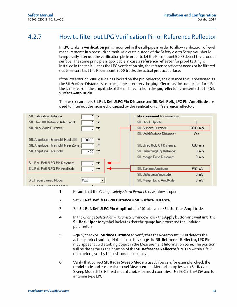
4.2.7 How to filter out LPG Verification Pin or Reference Reflector
In LPG tanks, a verification pin is mounted in the still-pipe in order to allow verification of level measurements in a pressurized tank. At a certain stage of the Safety Alarm Setup you should temporarily filter out the verification pin in order to let the Rosemount 5900 detect the product surface. The same principle is applicable in case a reference reflector for proof testing is installed in the tank. Just as the LPG verification pin, the reference reflector needs to be filtered out to ensure that the Rosemount 5900 tracks the actual product surface.
If the Rosemount 5900 gauge has locked on the pin/reflector, the distance to it is presented as the SIL Surface Distance since the gauge interprets the pin/reflector as the product surface. For the same reason, the amplitude of the radar echo from the pin/reflector is presented as the SIL Surface Amplitude.
The two parameters SIL Ref. Refl./LPG Pin Distance and SIL Ref. Refl./LPG Pin Amplitude are used to filter out the radar echo caused by the verification pin/reference reflector:
1. Ensure that the Change Safety Alarm Parameters window is open.
2. Set SIL Ref. Refl./LPG Pin Distance = SIL Surface Distance.
3. Set SIL Ref. Refl./LPG Pin Amplitude to 10% above the SIL Surface Amplitude.
4. In the Change Safety Alarm Parameters window, click the Apply button and wait until the SIL Bock Update symbol indicates that the gauge has processed the updated parameters.
5. Again, check SIL Surface Distance to verify that the Rosemount 5900 detects the actual product surface. Note that at this stage the SIL Reference Reflector/LPG Pin may appear as a disturbing object in the Measurement Information pane. The position will be the same as the position of the SIL Reference Reflector/LPG Pin within a few millimeter given by the instrument accuracy.
6. Verify that correct SIL Radar Sweep Mode is used. You can, for example, check the model code and ensure that Level Measurement Method complies with SIL Radar Sweep Mode. ETSI is the standard choice for most countries. Use FCC in the USA and for antenna type LPG.
43Installation and Configuration
Safety Manual00809-0200-5100, Rev GC
Installation and ConfigurationOctober 2019
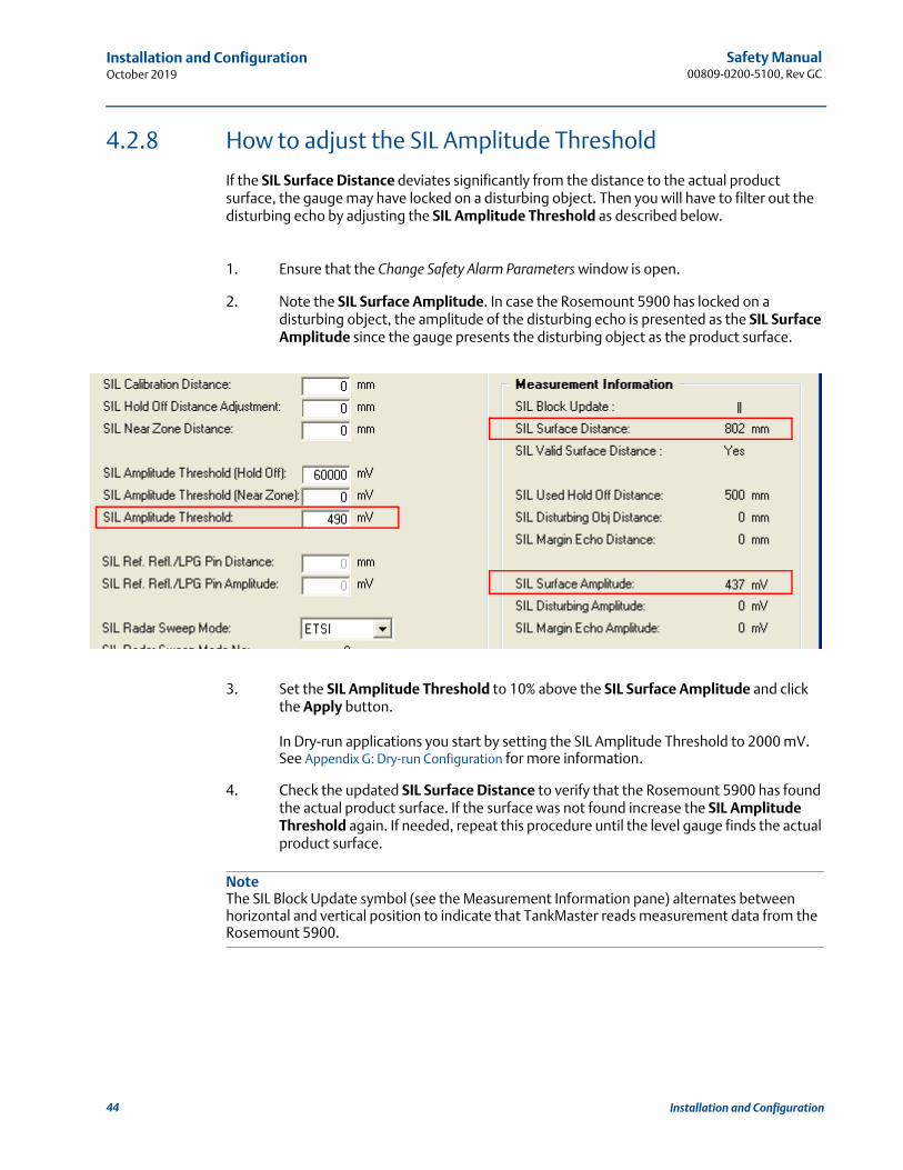
4.2.8 How to adjust the SIL Amplitude Threshold
If the SIL Surface Distance deviates significantly from the distance to the actual product surface, the gauge may have locked on a disturbing object. Then you will have to filter out the disturbing echo by adjusting the SIL Amplitude Threshold as described below.
1. Ensure that the Change Safety Alarm Parameters window is open.
2. Note the SIL Surface Amplitude. In case the Rosemount 5900 has locked on a disturbing object, the amplitude of the disturbing echo is presented as the SIL Surface Amplitude since the gauge presents the disturbing object as the product surface.
3. Set the SIL Amplitude Threshold to 10% above the SIL Surface Amplitude and click the Apply button.
In Dry-run applications you start by setting the SIL Amplitude Threshold to 2000 mV. See Appendix G: Dry-run Configuration for more information.
4. Check the updated SIL Surface Distance to verify that the Rosemount 5900 has found the actual product surface. If the surface was not found increase the SIL Amplitude Threshold again. If needed, repeat this procedure until the level gauge finds the actual product surface.
NoteThe SIL Block Update symbol (see the Measurement Information pane) alternates between horizontal and vertical position to indicate that TankMaster reads measurement data from the Rosemount 5900.
44 Installation and Configuration
Safety Manual 00809-0200-5100, Rev GC
Installation and ConfigurationOctober 2019
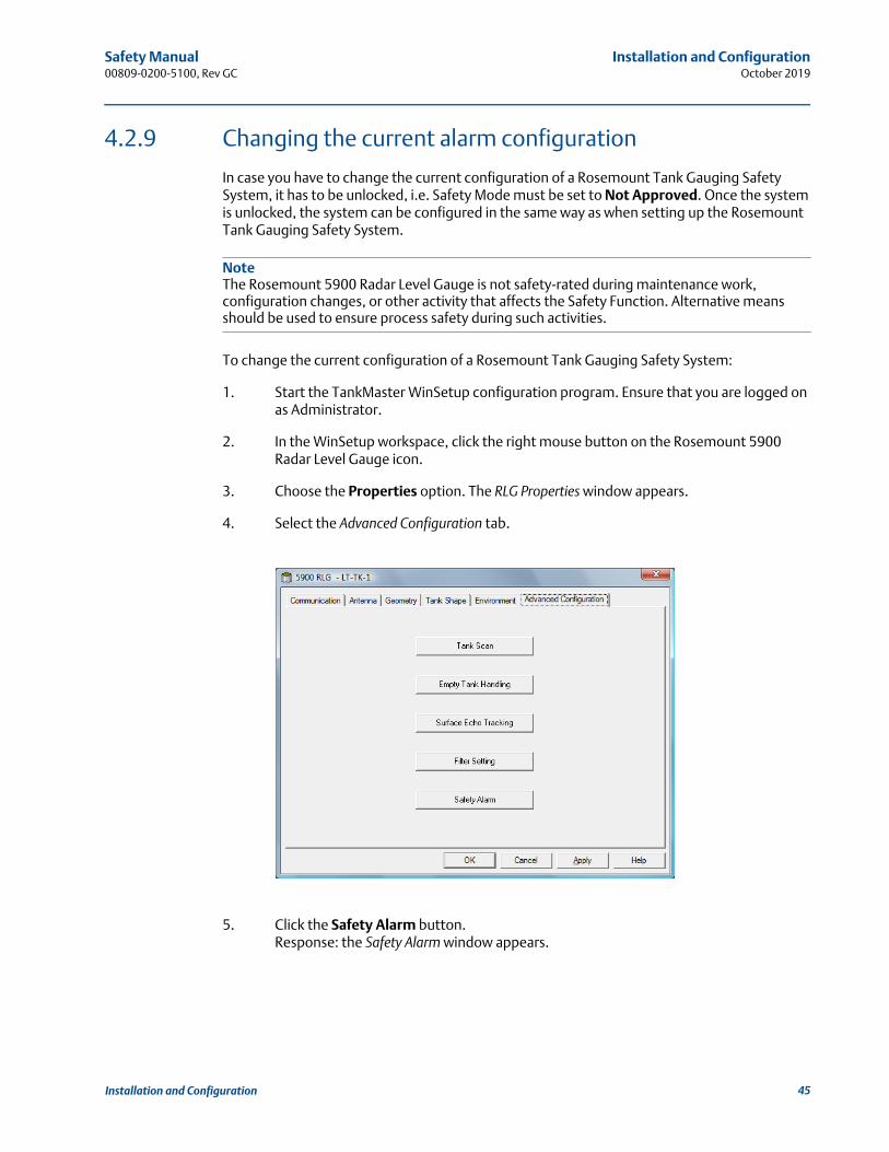
4.2.9 Changing the current alarm configuration
In case you have to change the current configuration of a Rosemount Tank Gauging Safety System, it has to be unlocked, i.e. Safety Mode must be set to Not Approved. Once the system is unlocked, the system can be configured in the same way as when setting up the Rosemount Tank Gauging Safety System.
NoteThe Rosemount 5900 Radar Level Gauge is not safety-rated during maintenance work, configuration changes, or other activity that affects the Safety Function. Alternative means should be used to ensure process safety during such activities.
To change the current configuration of a Rosemount Tank Gauging Safety System:
1. Start the TankMaster WinSetup configuration program. Ensure that you are logged on as Administrator.
2. In the WinSetup workspace, click the right mouse button on the Rosemount 5900 Radar Level Gauge icon.
3. Choose the Properties option. The RLG Properties window appears.
4. Select the Advanced Configuration tab.
5. Click the Safety Alarm button.Response: the Safety Alarm window appears.
45Installation and Configuration
Safety Manual00809-0200-5100, Rev GC
Installation and ConfigurationOctober 2019
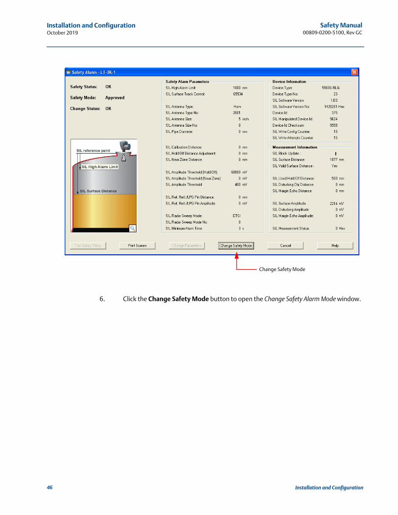
6. Click the Change Safety Mode button to open the Change Safety Alarm Mode window.
Change Safety Mode
46 Installation and Configuration

Safety Manual 00809-0200-5100, Rev GC
Installation and ConfigurationOctober 2019
7. In the Change Safety Alarm Mode window enter the Device Id and the SIL Password. The default password=”1234”. The password can be changed once the Safety Mode is set to “Not Approved”.
8. Click the Change to Not Approved button.
9. Close the Change Safety Alarm Mode window and return to the Safety Alarm window.
10. Follow the instructions in “Safety alarm configuration procedure” on page 32.
Change to Not Approved
Device IdPassword
47Installation and Configuration

Safety Manual00809-0200-5100, Rev GC
Installation and ConfigurationOctober 2019
4.2.10 How to adjust the SIL Hold Off Distance
In case the presented SIL Surface Distance indicates that the product surface is close to the nozzle, adjust the SIL Hold Off Distance instead of the SIL Amplitude Threshold. It is recommended that this method is used only if the disturbing echo is located more than 1 meter above the SIL High Alarm Limit.
1. Note the position of the disturbing echo. In case the gauge has locked on a disturbing echo, this position will be presented as the SIL Surface Distance. Also note the SIL Used Hold Off Distance.
2. Set the SIL Hold Off Distance Adjustment parameter so that the position of the disturbing echo is within the region defined by the SIL Used Hold Off Distance (see Figure 4-7 on page 20).
3. Click the Apply button.
4. Check the SIL Surface Distance and verify that the Rosemount 5900 gauge has found the actual product surface. If not, increase the SIL Hold Off Distance again. If needed, repeat this procedure until the Rosemount 5900 has found the actual product surface.
5. Click the Apply button to store the configuration.
48 Installation and Configuration

Safety Manual 00809-0200-5100, Rev GC
Installation and ConfigurationOctober 2019
4.2.11 How to enable SIL Low Alarm Limit
To enable the SIL Low Alarm Limit function:
1. In the Safety Alarm window, click the Change Parameters button to open the Change Safety Alarm Parameters window.
2. In the “Surface Track Control” field, type the desired SIL Low Alarm Limit value and click the Apply button.
3. Check that the “Surface Track Control” field is changed to SIL Low Alarm Limit.
SIL Surface Track Control
SIL Low Alarm Limit
49Installation and Configuration
Safety Manual00809-0200-5100, Rev GC
Installation and ConfigurationOctober 2019
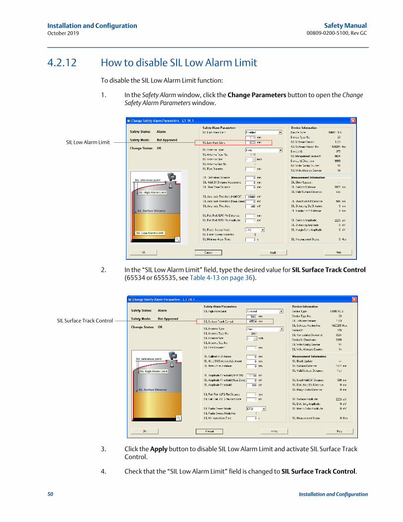
4.2.12 How to disable SIL Low Alarm Limit
To disable the SIL Low Alarm Limit function:
1. In the Safety Alarm window, click the Change Parameters button to open the Change Safety Alarm Parameters window.
2. In the “SIL Low Alarm Limit” field, type the desired value for SIL Surface Track Control (65534 or 655535, see Table 4-13 on page 36).
3. Click the Apply button to disable SIL Low Alarm Limit and activate SIL Surface Track Control.
4. Check that the “SIL Low Alarm Limit” field is changed to SIL Surface Track Control.
SIL Low Alarm Limit
SIL Surface Track Control
50 Installation and Configuration
Safety Manual 00809-0200-5100, Rev GC
Proof TestOctober 2019
Section 5 Proof Test
The Rosemount™ Tank Gauging Safety System should be checked at regular intervals in order to detect Dangerous Undetected (DU) failures.
The test must be repeated at regular intervals. The time periods depend on the PFDavg value. Note! Proof test for PFDavg calculations is only applicable for Low Demand mode.
The level measuring function can be verified via TankMaster WinOpi and TankMaster WinSetup.
For information about how to verify the relay function see “Verification of the relay function” on page 53.
Note The Rosemount 5900 gauge is not safety-rated during maintenance work, configuration changes, or other activity that affects the Safety Function. Alternative means should be used to ensure process safety during such activities.
One or more of the proof tests described below are recommended.
The SIL High Alarm test is performed by using a Reference Reflector as described in “SIL High Alarm test” on page 55.
Ensure that the proof test is performed with the same product type used when the tank was configured and approved for SIL Safety Alarm operation.
NoteFor a dual channel system (1oo2D(1)) complying with SIL 3 both level gauges must be tested.
(1) See “Functional specification of the safety function” on page 8.
51Proof Test

Safety Manual00809-0200-5100, Rev GC
Proof TestOctober 2019
5.1 Check of surface measurement and verification of the relay function
By combining the two tests Check of Surface Measurement and Verification of the Relay Function approximately 80% of the DU (dangerous undetected) failures will be detected.
5.1.1 Check of surface measurement
This proof test will detect approximately 48% of the DU (dangerous undetected) failures not detected by the diagnostics in the Rosemount Tank Gauging Safety System:
Compare the SIL Surface Distance value presented in the Safety Alarm window with a second reference such as the BPCS level sensor or a manual hand dip (see the Rosemount 5900S Reference Manual, Document No. 00809-0100-5900, for a description of how to perform hand dipping)
Verify that the amplitude (SIL Surface Amplitude) is at least 100% greater than the SIL Amplitude Threshold
With the surface close to the dry-run alarm limit, check that no margin peak is present anywhere above the surface
52 Proof Test

Safety Manual 00809-0200-5100, Rev GC
Proof TestOctober 2019
5.1.2 Verification of the relay function
This proof test verifies the Safety Relay function itself, i.e. whether the Safety Relay is able to open and close.
The test will detect approximately 35% of the DU (dangerous undetected) failures not detected by the diagnostics in the Rosemount Tank Gauging Safety System.
To test the relay function, follow the procedure described below:
1. in the Change Safety Alarm Mode window, disable SIL mode by changing to Not Approved:
a. Open the Safety Alarm window.
b. Click the Change Safety Mode button.
c. Enter Device Id and SIL Password.
d. Click the Change to Not Approved button.
2. Check that the relay is de-energized. Verify that Safety status is “Alarm”.
3. In the Safety Alarm window click the Test Safety Relay button. Check that the relay is energized for 30 seconds.
4. In the Change Safety Alarm Mode window enable SIL mode by changing to Approved.
53Proof Test

Safety Manual00809-0200-5100, Rev GC
Proof TestOctober 2019
5.2 System test
This proof test will detect approximately 99% of the DU (dangerous undetected) failures not detected by the diagnostics in the Rosemount Tank Gauging Safety System. The test includes testing the relay response when the product surface reaches the relay set point.
The overfill and dry-run protection function should be checked by filling and emptying the tank in order to test the system response when the product surface reaches the relay set points.
In case it is a dual channel system (1oo2D(1)) complying with SIL 3, verify that both level gauges trigger the alarm.
(1) See “Functional specification of the safety function” on page 8.
54 Proof Test
Safety Manual 00809-0200-5100, Rev GC
Proof TestOctober 2019
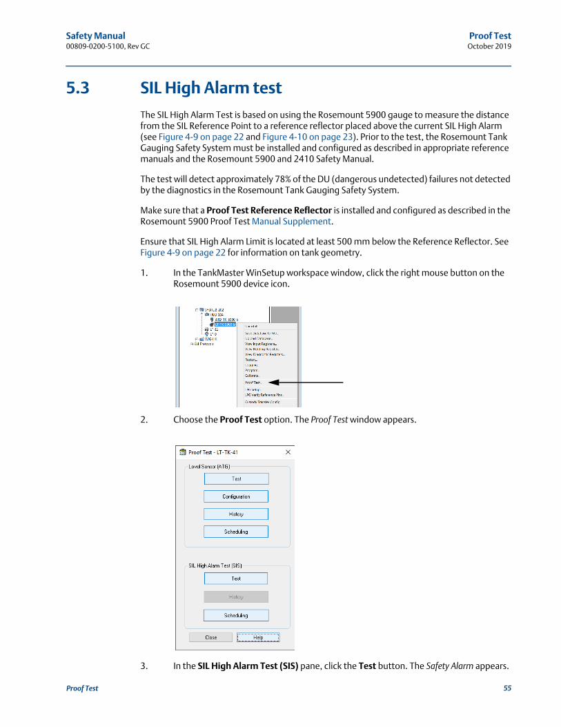
5.3 SIL High Alarm test
The SIL High Alarm Test is based on using the Rosemount 5900 gauge to measure the distance from the SIL Reference Point to a reference reflector placed above the current SIL High Alarm (see Figure 4-9 on page 22 and Figure 4-10 on page 23). Prior to the test, the Rosemount Tank Gauging Safety System must be installed and configured as described in appropriate reference manuals and the Rosemount 5900 and 2410 Safety Manual.
The test will detect approximately 78% of the DU (dangerous undetected) failures not detected by the diagnostics in the Rosemount Tank Gauging Safety System.
Make sure that a Proof Test Reference Reflector is installed and configured as described in the Rosemount 5900 Proof Test Manual Supplement.
Ensure that SIL High Alarm Limit is located at least 500 mm below the Reference Reflector. See Figure 4-9 on page 22 for information on tank geometry.
1. In the TankMaster WinSetup workspace window, click the right mouse button on the Rosemount 5900 device icon.
2. Choose the Proof Test option. The Proof Test window appears.
3. In the SIL High Alarm Test (SIS) pane, click the Test button. The Safety Alarm appears.
55Proof Test

Safety Manual00809-0200-5100, Rev GC
Proof TestOctober 2019
4. Verify that the SIL Reference Reflector/LPG Pin Distance and SIL Reference Reflector/LPG Pin Amplitude parameters are displayed. In case no Reference Reflector is installed, these parameters will be equal to zero and the Test SIL High Alarm button will be disabled.
5. Click the Test SIL High Alarm button.
6. Click the Accept button to continue.
56 Proof Test

Safety Manual 00809-0200-5100, Rev GC
Proof TestOctober 2019
7. In the Test SIL High Alarm window, verify the current test time, or change the test time to the desired value.
8. Enter your signature.
9. Click the Start Test button to start the test procedure. The SIL High Alarm Test Data window with updated parameters will appear. During the SIL High Alarm test, the gauge measures the distance to the Reference Reflector and will present it as the SIL Surface Distance. Safety Status will be changed to Alarm since the Reference Reflector is located within the High Alarm region. When the test is finished, the gauge returns to measure the distance to the actual product surface, and the SIL High Alarm Test Data window is automatically closed.
The Stop Test button allows you to stop the test before the specified test time has elapsed. You will still be able to fill in the test report form in order to generate a test report file in pdf format. Pressing the Cancel button stops the test and no report will be generated. See Table 5-1 on page 59 for information on the various Safety Alarm Parameters displayed in the SIL High Alarm Test Results window and in the test report.
If no bar graph appears and the Stop Test button is disabled, the gauge was not able to start the test. This may happen if, for example, the Reference Reflector has been removed, or if amplitude thresholds are not properly configured. In that case, click the Cancel button to close the window, and check that the Reference Reflector is properly installed and configured. You should also check the Safety Alarm Parameters in the Safety Alarm window for possible errors.
57Proof Test
Safety Manual00809-0200-5100, Rev GC
Proof TestOctober 2019
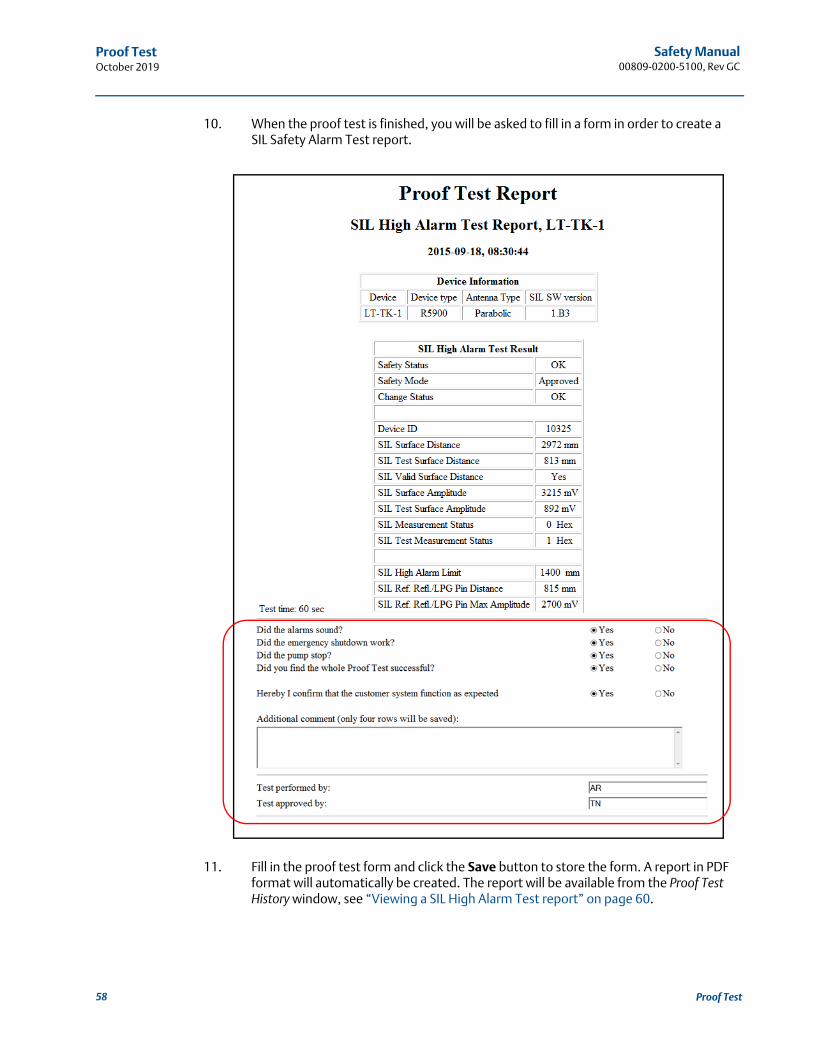
10. When the proof test is finished, you will be asked to fill in a form in order to create a SIL Safety Alarm Test report.
11. Fill in the proof test form and click the Save button to store the form. A report in PDF format will automatically be created. The report will be available from the Proof Test History window, see “Viewing a SIL High Alarm Test report” on page 60.
58 Proof Test

Safety Manual 00809-0200-5100, Rev GC
Proof TestOctober 2019
The following parameters will be presented in the report and the SIL High Alarm Test Results window:
Table 5-1. Safety parameters
Safety Parameter Description
Safety Status “Alarm” during the SIL High Alarm test. Once the test is finished successfully, Safety Status will return to “OK”. In the Proof Test Report Safety Status will be set to “OK” as well.
Safety Mode Should be “Approved” prior to the test is started as well as when the SIL High Alarm test is performed.
SIL Surface Distance Normally this is the distance from the SIL Reference Point to the product surface. During the SIL High Alarm Test the Rosemount 5900 level gauge measures the distance to the Reference Reflector.
SIL Test Surface Distance Measured distance to the Reference Reflector which simulates the product surface during the SIL High Alarm Test.
SIL Valid Surface Distance “Yes” if the gauge finds a valid echo from the product surface or the Reference Reflector.
SIL Surface Amplitude This is the amplitude of the radar signal reflected by the product surface. During the SIL High Alarm Test the amplitude refers to the signal reflected by the Reference Reflector which is presented as the SIL Test Surface Amplitude in the test report.
SIL Test Surface Amplitude Amplitude of the radar signal reflected by the Reference Reflector during the SIL High Alarm Test.
SIL Measurement Status Equal to 1 during SIL High Alarm Test indicating that measurement is performed within the High Alarm region. Equal to 0 in normal conditions when the product surface is located below the SIL High Alarm.
59Proof Test

Safety Manual00809-0200-5100, Rev GC
Proof TestOctober 2019
5.3.1 Viewing a SIL High Alarm Test report
Reports in Adobe Acrobat pdf format are available via the Proof Test History window.
To view a report:
1. Open the Proof Test window.
2. In the SIL High Alarm Test (SIS) pane, click the History button.
60 Proof Test
Safety Manual 00809-0200-5100, Rev GC
Proof TestOctober 2019
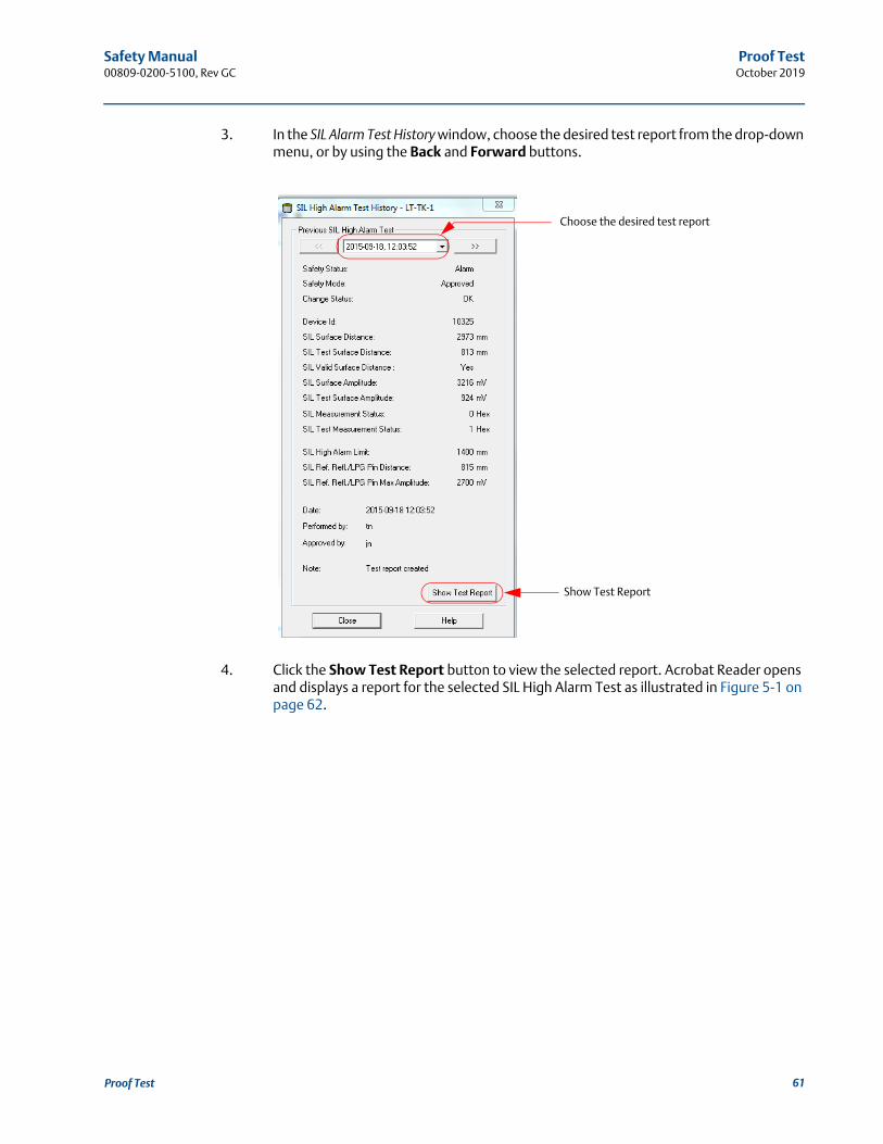
3. In the SIL Alarm Test History window, choose the desired test report from the drop-down menu, or by using the Back and Forward buttons.
4. Click the Show Test Report button to view the selected report. Acrobat Reader opens and displays a report for the selected SIL High Alarm Test as illustrated in Figure 5-1 on page 62.
Show Test Report
Choose the desired test report
61Proof Test
Safety Manual00809-0200-5100, Rev GC
Proof TestOctober 2019
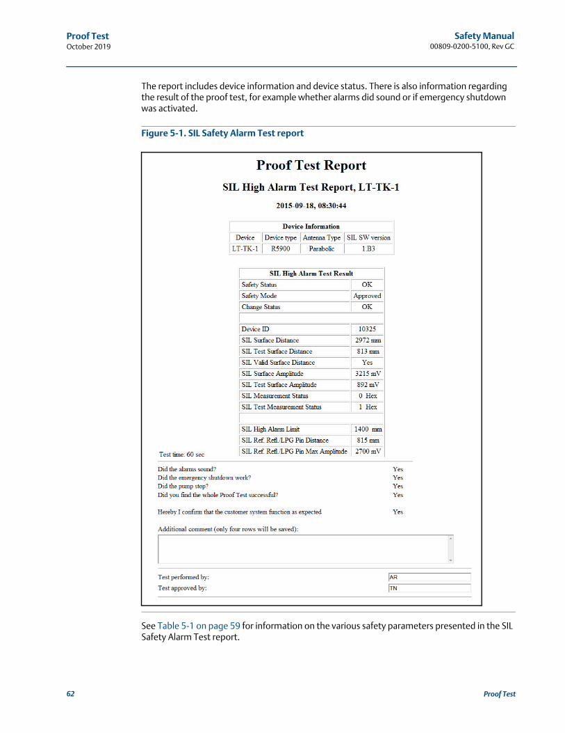
The report includes device information and device status. There is also information regarding the result of the proof test, for example whether alarms did sound or if emergency shutdown was activated.
Figure 5-1. SIL Safety Alarm Test report
See Table 5-1 on page 59 for information on the various safety parameters presented in the SIL Safety Alarm Test report.
62 Proof Test

Safety Manual 00809-0200-5100, Rev GC
Terms and DefinitionsOctober 2019
Section 6 Terms and Definitions
BPCS Basic Process Control System
Demand rate How often it will be required from a safety integrity system (or the safety function) to react on inputs from process to bring it into a safe state, i.e. to issue an alarm
FIT Failure in Time (1 FIT = 1failure/109 h)
FMEDA Failure Modes, Effects and Diagnostics Analysis
HFT Hardware Fault Tolerance
High mode of operation The safety function is only performed on demand, in order to transfer the EUC into a specified safe state, and the frequency of demands is greater than one per year
Low mode of operation The safety function is only performed on demand, in order to transfer the EUC into a specified safe state, and the frequency of demands is no greater than one per year
Mode of operation The way in which a safety function operates, which may be either low mode of operation or high mode of operation
PFDavg Average probability of Failure on Demand
PFH (average frequency of a dangerous failure per hour)
Average frequency of a dangerous failure of an E/E/PE safety related system to perform the specified safety function over a given period of time
SFF Safe Failure Fraction summarizes the fraction of failures, which lead to a safe state and the fraction of failures which will be detected by diagnostic measures and lead to a defined safety action.
SIF Safety Instrumented Function
SIL Safety Integrity Level
SIL Reference Point The SIL Reference Point is located at the flange of the Rosemount 5900 Radar Level Gauge. It used as reference point for the SIL High and Low Alarm Limits.
SIS Safety Instrumented System
Type B component Complex component (using micro controllers or programmable logic)
1oo1D Architecture consisting of a single channel with additional diagnostic capabilities.
1oo2D Architecture consisting of two channels (level gauges) connected in parallel with additional diagnostic capabilities. During normal operation the system goes to alarm if either channel (level gauge) indicates an alarm condition
63Terms and Definitions

Safety Manual00809-0200-5100, Rev GC
Terms and DefinitionsOctober 2019
64 Terms and Definitions
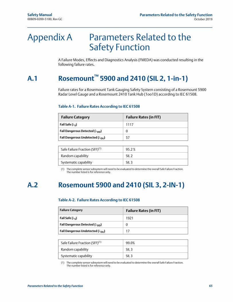
Safety Manual 00809-0200-5100, Rev GC
Parameters Related to the Safety FunctionOctober 2019
Appendix A Parameters Related to the Safety Function
A Failure Modes, Effects and Diagnostics Analysis (FMEDA) was conducted resulting in the following failure rates.
A.1 Rosemount™ 5900 and 2410 (SIL 2, 1-in-1)
Failure rates for a Rosemount Tank Gauging Safety System consisting of a Rosemount 5900 Radar Level Gauge and a Rosemount 2410 Tank Hub (1oo1D) according to IEC 61508.
Table A-1. Failure Rates According to IEC 61508
A.2 Rosemount 5900 and 2410 (SIL 3, 2-IN-1)
Table A-2. Failure Rates According to IEC 61508
Failure Category Failure Rates (in FIT)
Fail Safe (S) 1117
Fail Dangerous Detected (DD) 0
Fail Dangerous Undetected (DU) 57
Safe Failure Fraction (SFF)(1)
(1) The complete sensor subsystem will need to be evaluated to determine the overall Safe Failure Fraction. The number listed is for reference only.
95.2 %
Random capability SIL 2
Systematic capability SIL 3
Failure Category Failure Rates (in FIT)
Fail Safe (S) 1921
Fail Dangerous Detected (DD) 0
Fail Dangerous Undetected (DU) 17
Safe Failure Fraction (SFF)(1)
(1) The complete sensor subsystem will need to be evaluated to determine the overall Safe Failure Fraction. The number listed is for reference only.
99.0%
Random capability SIL 3
Systematic capability SIL 3
65Parameters Related to the Safety Function

Safety Manual00809-0200-5100, Rev GC
Parameters Related to the Safety FunctionOctober 2019
A.3 Rosemount 5900 and 2410 (SIL 2, 2-in-1)
Table A-3. Failure Rates According to IEC 61508
Failure Category Failure Rates (in FIT)
Fail Safe (S) 1117
Fail Dangerous Detected (DD) 0
Fail Dangerous Undetected (DU) 57
Safe Failure Fraction (SFF)(1)
(1) The complete sensor subsystem will need to be evaluated to determine the overall Safe Failure Fraction. The number listed is for reference only.
95.2 %
Random capability SIL 2
Systematic capability SIL 3
66 Parameters Related to the Safety Function
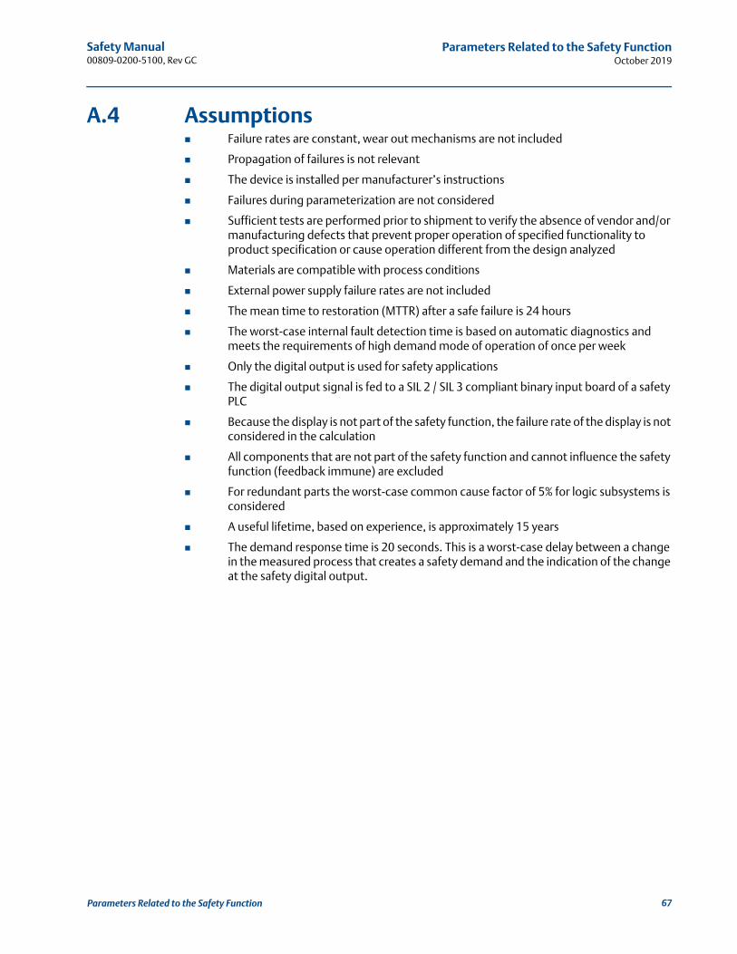
Safety Manual 00809-0200-5100, Rev GC
Parameters Related to the Safety FunctionOctober 2019
A.4 Assumptions Failure rates are constant, wear out mechanisms are not included
Propagation of failures is not relevant
The device is installed per manufacturer’s instructions
Failures during parameterization are not considered
Sufficient tests are performed prior to shipment to verify the absence of vendor and/or manufacturing defects that prevent proper operation of specified functionality to product specification or cause operation different from the design analyzed
Materials are compatible with process conditions
External power supply failure rates are not included
The mean time to restoration (MTTR) after a safe failure is 24 hours
The worst-case internal fault detection time is based on automatic diagnostics and meets the requirements of high demand mode of operation of once per week
Only the digital output is used for safety applications
The digital output signal is fed to a SIL 2 / SIL 3 compliant binary input board of a safety PLC
Because the display is not part of the safety function, the failure rate of the display is not considered in the calculation
All components that are not part of the safety function and cannot influence the safety function (feedback immune) are excluded
For redundant parts the worst-case common cause factor of 5% for logic subsystems is considered
A useful lifetime, based on experience, is approximately 15 years
The demand response time is 20 seconds. This is a worst-case delay between a change in the measured process that creates a safety demand and the indication of the change at the safety digital output.
67Parameters Related to the Safety Function

Safety Manual00809-0200-5100, Rev GC
Parameters Related to the Safety FunctionOctober 2019
68 Parameters Related to the Safety Function
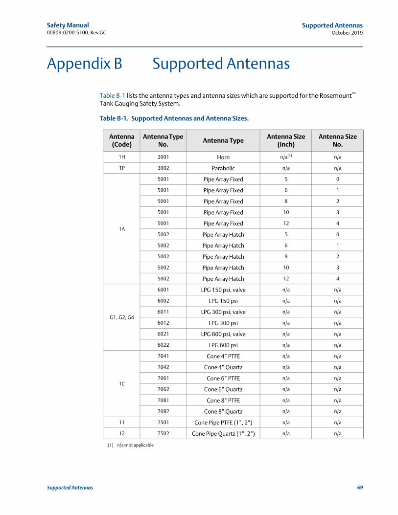
Safety Manual 00809-0200-5100, Rev GC
Supported AntennasOctober 2019
Appendix B Supported Antennas
Table B-1 lists the antenna types and antenna sizes which are supported for the Rosemount™ Tank Gauging Safety System.
Table B-1. Supported Antennas and Antenna Sizes.
Antenna (Code)
Antenna Type No.
Antenna TypeAntenna Size
(inch)Antenna Size
No.
1H 2001 Horn n/a(1)
(1) n/a=not applicable
n/a
1P 3002 Parabolic n/a n/a
1A
5001 Pipe Array Fixed 5 0
5001 Pipe Array Fixed 6 1
5001 Pipe Array Fixed 8 2
5001 Pipe Array Fixed 10 3
5001 Pipe Array Fixed 12 4
5002 Pipe Array Hatch 5 0
5002 Pipe Array Hatch 6 1
5002 Pipe Array Hatch 8 2
5002 Pipe Array Hatch 10 3
5002 Pipe Array Hatch 12 4
G1, G2, G4
6001 LPG 150 psi, valve n/a n/a
6002 LPG 150 psi n/a n/a
6011 LPG 300 psi, valve n/a n/a
6012 LPG 300 psi n/a n/a
6021 LPG 600 psi, valve n/a n/a
6022 LPG 600 psi n/a n/a
1C
7041 Cone 4” PTFE n/a n/a
7042 Cone 4” Quartz n/a n/a
7061 Cone 6” PTFE n/a n/a
7062 Cone 6” Quartz n/a n/a
7081 Cone 8” PTFE n/a n/a
7082 Cone 8” Quartz n/a n/a
11 7501 Cone Pipe PTFE (1”, 2”) n/a n/a
12 7502 Cone Pipe Quartz (1”, 2”) n/a n/a
69Supported Antennas

Safety Manual00809-0200-5100, Rev GC
Supported AntennasOctober 2019
70 Supported Antennas

Safety Manual 00809-0200-5100, Rev GC
Safety System IdentificationOctober 2019
Appendix C Safety System Identification
Valid software and hardware versions:
Rosemount™ 5900 software version 1.B2, 1.B3, 1.C0, 1.D0, 1.E0
SIL Baseline BS3, BS4 (see main label)
A Rosemount Tank Gauging Safety System is identified by a unique SIL Baseline as specified in the Functional Safety Certificate. The Baseline contains information about correct version of hardware, software, and other relevant configuration items.
Baseline 3 and 4 for Rosemount 5900S or Rosemount 2410 can be combined.
NoteFor configuration software TankMaster WinSetup, versions according to Table C-1apply.
Table C-1. TankMaster WinSetup Software Versions
C.1 Device Id
The Device Id of a Rosemount 5900 gauge with 2-in-1 option consists of two parts: “xxx-yyy”, where “xxx” is the Device Id of the primary device and “yyy” is the Device Id of the secondary device.
Example
Device Id: 443-438
Primary Device Device Id: 443
Secondary Device Device Id: 438
Function WinSetup version
SIL support 6.A2
dry-run support 6.B4
support for cone antennas 6.B6
SIL High Alarm Test 6.C0
71Safety System Identification

Safety Manual00809-0200-5100, Rev GC
Safety System IdentificationOctober 2019
C.2 Baselines
Ensure that the SIL Baselines for the Rosemount 5900 Radar Level Gauge and the Rosemount 2410 Tank Hub are identical when a new Rosemount Tank Gauging Safety System is installed.
Figure C-1. Rosemount 5900 Main Label
Figure C-2. Rosemount 2410 Main Label
Check the Model code and the SIL Level information on the main label to ensure that the ordered SIL Level corresponds with the shipped Rosemount Tank Gauging Safety System devices.
SIL Baseline and SIL Level
Model code
Serial no.
Device ID
Model code
Serial no.
SIL 2 / SIL 3
SIL Level and SIL Baseline
72 Safety System Identification

Safety Manual 00809-0200-5100, Rev GC
Safety System IdentificationOctober 2019
C.3 SIL Level
Verify the correct SIL level (SIL 2/SIL 3) as illustrated in Figure C-3.
Figure C-3. Rosemount 5900 Terminal Block with SIL Label
The Rosemount 5900 has different terminal blocks for the SIL 2 and SIL 3 options. The SIL 3 option includes two separate level gauges which need to be configured individually as described in “Safety alarm setup” on page 19. Check the label in the terminal block to ensure that the Rosemount 5900 has the right option for the required SIL safety level.
SIL 2/S I L 3 label
73Safety System Identification

Safety Manual00809-0200-5100, Rev GC
Safety System IdentificationOctober 2019
74 Safety System Identification

Safety Manual 00809-0200-5100, Rev GC
SIL Measurement StatusOctober 2019
Appendix D SIL Measurement Status
In the Safety Alarm and other windows the current measurement status is presented in the Measurement Status field. In case of an error, it displays a status code in hexadecimal format according to Table D-1.
In normal operation the SIL Measurement Status is equal to zero.
Figure D-1. SIL Measurement Status field
SIL Measurement Status
75SIL Measurement Status
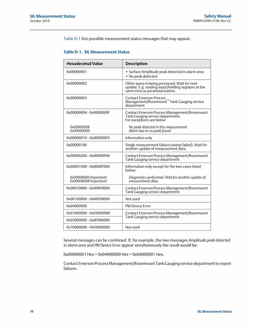
Safety Manual00809-0200-5100, Rev GC
SIL Measurement StatusOctober 2019
Table D-1 lists possible measurement status messages that may appear.
Table D-1. SIL Measurement Status
Several messages can be combined. If, for example, the two messages Amplitude peak detected in alarm area and PM Device Error appear simultaneously the result would be:
0x00000001 Hex + 0x04000000 Hex = 0x04000001 Hex.
Contact Emerson Process Management/Rosemount Tank Gauging service department to report failures.
Hexadecimal Value Description
0x00000001 • Surface Amplitude peak detected in alarm area• No peak detected
0x00000002 Other query is being processed. Wait for next update. E.g. reading input/holding registers at the same time as parameterization.
0x00000003 Contact Emerson Process Management/Rosemount™ Tank Gauging service department
0x00000004 - 0x0000000F Contact Emerson Process Management/Rosemount Tank Gauging service department.For exceptions see below:
0x000000080x00000009
No peak detected in this measurementAlarm due to no peak found
0x00000010 - 0x000000F0 Information only
0x00000180 Single measurement failure (sweep failed). Wait for another update of measurement data.
0x00000200 - 0x00000F00 Contact Emerson Process Management/Rosemount Tank Gauging service department
0x00001000 - 0x0000F000 Information only except for the two cases listed below:
0x00008000 Important!0x00008008 Important!
Diagnostics performed. Wait for another update of measurement data.
0x00010000 - 0x000F0000 Contact Emerson Process Management/Rosemount Tank Gauging service department
0x00100000 - 0x00F00000 Not used
0x04000000 PM Device Error
0x01000000 - 0x03000000 Contact Emerson Process Management/Rosemount Tank Gauging service department
0x05000000 - 0x0F000000
0x10000000 - 0xF0000000 Not used
76 SIL Measurement Status

Safety Manual 00809-0200-5100, Rev GC
Disabling the SIL High AlarmOctober 2019
Appendix E Disabling the SIL High Alarm
The Disable SIL High Alarm function may be useful in dry-run applications when only SIL Low Alarm Limit is needed.
Two options are available for disabling the SIL High Alarm:
Option “0” disables SIL High Alarm Limit. The alarm will still be triggered if the gauge loses track of the product surface.
Option “1” may be used to avoid false alarms in case the gauge loses track of the product surface for short periods of time.
NoteMake sure that the product surface is detected by the Rosemount™ 5900 gauge prior to disabling the SIL High Alarm.
Ensure that appropriate measures are taken to prevent overfill in case the SIL High Alarm is disabled.
77Disabling the SIL High Alarm
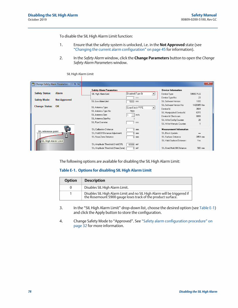
Safety Manual00809-0200-5100, Rev GC
Disabling the SIL High AlarmOctober 2019
To disable the SIL High Alarm Limit function:
1. Ensure that the safety system is unlocked, i.e. in the Not Approved state (see “Changing the current alarm configuration” on page 45 for information).
2. In the Safety Alarm window, click the Change Parameters button to open the Change Safety Alarm Parameters window.
The following options are available for disabling the SIL High Alarm Limit:
Table E-1. Options for disabling SIL High Alarm Limit
3. In the “SIL High Alarm Limit” drop-down list, choose the desired option (see Table E-1) and click the Apply button to store the configuration.
4. Change Safety Mode to “Approved”. See “Safety alarm configuration procedure” on page 32 for more information.
Option Description
0 Disables SIL High Alarm Limit.
1 Disables SIL High Alarm Limit and no SIL High Alarm will be triggered if the Rosemount 5900 gauge loses track of the product surface.
SIL High Alarm Limit
78 Disabling the SIL High Alarm
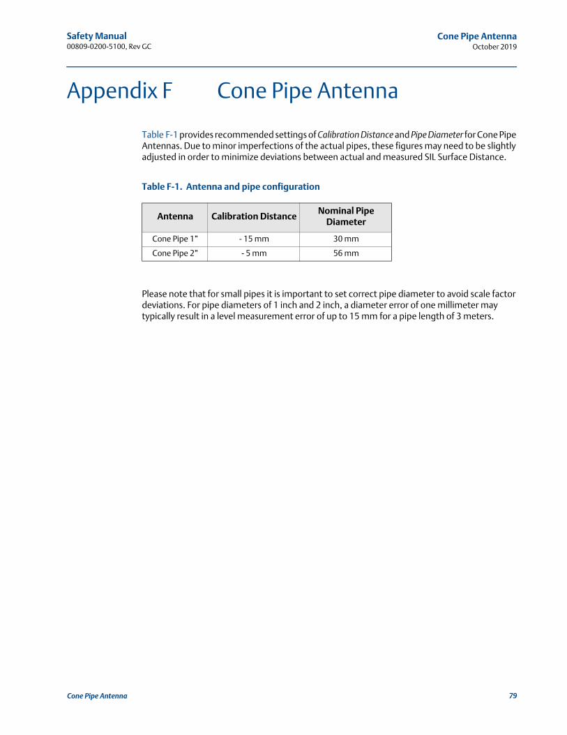
Safety Manual 00809-0200-5100, Rev GC
Cone Pipe AntennaOctober 2019
Appendix F Cone Pipe Antenna
Table F-1 provides recommended settings of Calibration Distance and Pipe Diameter for Cone Pipe Antennas. Due to minor imperfections of the actual pipes, these figures may need to be slightly adjusted in order to minimize deviations between actual and measured SIL Surface Distance.
Table F-1. Antenna and pipe configuration
Please note that for small pipes it is important to set correct pipe diameter to avoid scale factor deviations. For pipe diameters of 1 inch and 2 inch, a diameter error of one millimeter may typically result in a level measurement error of up to 15 mm for a pipe length of 3 meters.
Antenna Calibration DistanceNominal Pipe
Diameter
Cone Pipe 1” - 15 mm 30 mm
Cone Pipe 2” - 5 mm 56 mm
79Cone Pipe Antenna

Safety Manual00809-0200-5100, Rev GC
Cone Pipe AntennaOctober 2019
80 Cone Pipe Antenna
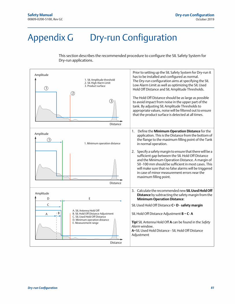
Safety Manual 00809-0200-5100, Rev GC
Dry-run ConfigurationOctober 2019
Appendix G Dry-run Configuration
This section describes the recommended procedure to configure the SIL Safety System for Dry-run applications.
Prior to setting up the SIL Safety System for Dry-run it has to be installed and configured as normal.The Dry-run configuration aims at specifying the SIL Low Alarm Limit as well as optimizing the SIL Used Hold Off Distance and SIL Amplitude Thresholds.
The Hold Off Distance should be as large as possible to avoid impact from noise in the upper part of the tank. By adjusting SIL Amplitude Thresholds to appropriate values, noise will be filtered out to ensure that the product surface is detected at all times.
1. Define the Minimum Operation Distance for the application. This is the Distance from the bottom of the flange to the maximum filling point of the Tank in normal operation.
2. Specify a safety margin to ensure that there will be a sufficient gap between the SIL Hold Off Distance and the Minimum Operation Distance. A margin of 50 -100 mm should be sufficient in most cases. This will make sure that no false alarms will be triggered in case of minor measurement errors near the maximum filling point.
3. Calculate the recommended new SIL Used Hold Off Distance by subtracting the safety margin from the Minimum Operation Distance:
SIL Used Hold Off Distance C= D - safety margin
SIL Hold Off Distance Adjustment B = C- A
Tip! SIL Antenna Hold Off A can be found in the Safety Alarm window.A=SIL Used Hold Distance - SIL Hold Off Distance Adjustment
1. SIL Amplitude threshold2. SIL High Alarm Limit3. Product surface
Distance
Amplitude
3
1
2
1. Minimum operation distance
Distance
Amplitude
1
C
A BA. SIL Antenna Hold OffB. SIL Hold Off Distance AdjustmentC. SIL Used Hold Off DistanceD. Minimum operation distanceE. Measurement range
ED
Distance
Amplitude
81Dry-run Configuration
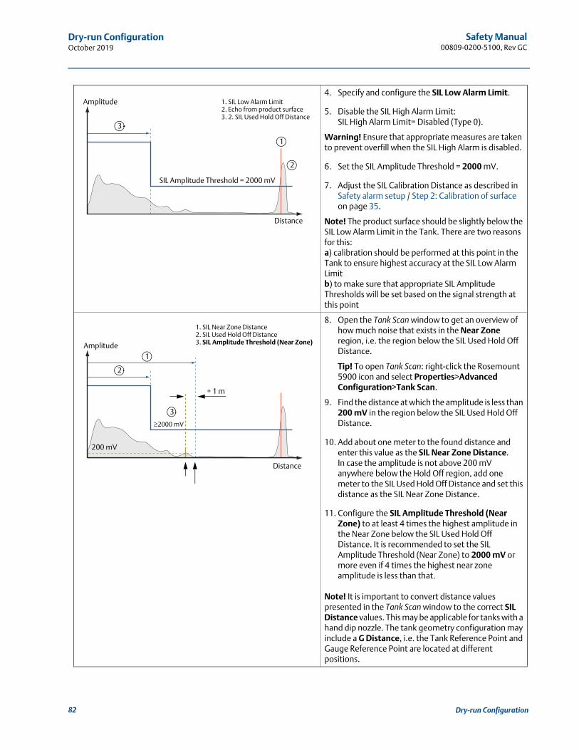
Safety Manual00809-0200-5100, Rev GC
Dry-run ConfigurationOctober 2019
4. Specify and configure the SIL Low Alarm Limit.
5. Disable the SIL High Alarm Limit:SIL High Alarm Limit= Disabled (Type 0).
Warning! Ensure that appropriate measures are taken to prevent overfill when the SIL High Alarm is disabled.
6. Set the SIL Amplitude Threshold = 2000 mV.
7. Adjust the SIL Calibration Distance as described in Safety alarm setup / Step 2: Calibration of surface on page 35.
Note! The product surface should be slightly below the SIL Low Alarm Limit in the Tank. There are two reasons for this: a) calibration should be performed at this point in the Tank to ensure highest accuracy at the SIL Low Alarm Limitb) to make sure that appropriate SIL Amplitude Thresholds will be set based on the signal strength at this point
8. Open the Tank Scan window to get an overview of how much noise that exists in the Near Zone region, i.e. the region below the SIL Used Hold Off Distance.
Tip! To open Tank Scan: right-click the Rosemount 5900 icon and select Properties>Advanced Configuration>Tank Scan.
9. Find the distance at which the amplitude is less than 200 mV in the region below the SIL Used Hold Off Distance.
10. Add about one meter to the found distance and enter this value as the SIL Near Zone Distance. In case the amplitude is not above 200 mV anywhere below the Hold Off region, add one meter to the SIL Used Hold Off Distance and set this distance as the SIL Near Zone Distance.
11. Configure the SIL Amplitude Threshold (Near Zone) to at least 4 times the highest amplitude in the Near Zone below the SIL Used Hold Off Distance. It is recommended to set the SIL Amplitude Threshold (Near Zone) to 2000 mV or more even if 4 times the highest near zone amplitude is less than that.
Note! It is important to convert distance values presented in the Tank Scan window to the correct SIL Distance values. This may be applicable for tanks with a hand dip nozzle. The tank geometry configuration may include a G Distance, i.e. the Tank Reference Point and Gauge Reference Point are located at different positions.
SIL Amplitude Threshold = 2000 mV
1. SIL Low Alarm Limit2. Echo from product surface3. 2. SIL Used Hold Off Distance
Distance
Amplitude
1
2
3
200 mV
+ 1 m
1. SIL Near Zone Distance2. SIL Used Hold Off Distance3. SIL Amplitude Threshold (Near Zone)
Distance
Amplitude
3
1
2
2000 mV
82 Dry-run Configuration
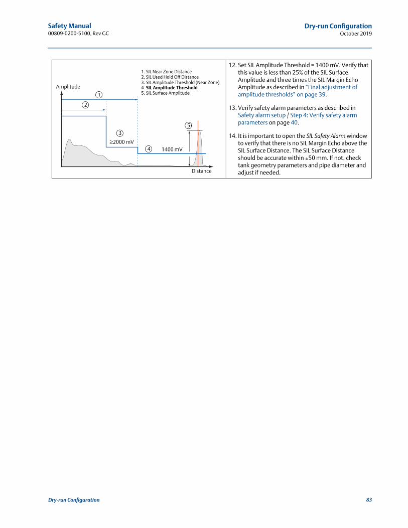
Safety Manual 00809-0200-5100, Rev GC
Dry-run ConfigurationOctober 2019
12. Set SIL Amplitude Threshold = 1400 mV. Verify that this value is less than 25% of the SIL Surface Amplitude and three times the SIL Margin Echo Amplitude as described in “Final adjustment of amplitude thresholds” on page 39.
13. Verify safety alarm parameters as described in Safety alarm setup / Step 4: Verify safety alarm parameters on page 40.
14. It is important to open the SIL Safety Alarm window to verify that there is no SIL Margin Echo above the SIL Surface Distance. The SIL Surface Distance should be accurate within ±50 mm. If not, check tank geometry parameters and pipe diameter and adjust if needed.
3
1. SIL Near Zone Distance2. SIL Used Hold Off Distance3. SIL Amplitude Threshold (Near Zone)4. SIL Amplitude Threshold5. SIL Surface Amplitude
Amplitude
Distance
1400 mV
1
2
2000 mV
5
4
83Dry-run Configuration

Safety Manual00809-0200-5100, Rev GC
Dry-run ConfigurationOctober 2019
84 Dry-run Configuration

Safety Manual00809-0200-5100, Rev GC
October 2019
Global Headquarters and Europe Regional OfficeTank GaugingEmerson Automation Solutions Box 150(Visiting address: Layoutvägen 1)SE-435 23 Mölnlycke
+46 31 337 00 00+46 31 25 30 [email protected]
North America Regional OfficeTank GaugingEmerson Automation Solutions 6005 Rogerdale RoadMail Stop NC 136Houston TX 77072United States
+1 281 988 4000 or +1 800 722 [email protected]
Latin America Regional OfficeEmerson Automation Solutions 1300 Concord Terrace, Suite 400Sunrise, FL 33323, USA
+1 954 846 5030+1 954 846 [email protected]
Asia Pacific Regional OfficeEmerson Automation Solutions Asia Pacific Pte Ltd1 Pandan CrescentSingapore 128461
+65 6777 8211+65 6777 0947 [email protected]
Middle East and Africa Regional OfficeEmerson Automation Solutions Emerson FZE P.O. Box 17033Jebel Ali Free Zone - South 2Dubai, United Arab Emirates
+971 4 8118100+971 4 8865465 [email protected]
Linkedin.com/company/Emerson-Process-Management
Twitter.com/Rosemount_News
Facebook.com/Rosemount
Youtube.com/user/RosemountMeasurement
Google.com/+RosemountMeasurement
Standard Terms and Conditions of Sale can be found at: www.emerson.com/en-us/Terms-of-Use.The Emerson logo is a trademark and service mark of Emerson Electric Co.Rosemount and Rosemount logotype are trademarks of Emerson.All other marks are the property of their respective owners.© 2019 Emerson. All rights reserved.