Embed Size (px)
Citation preview
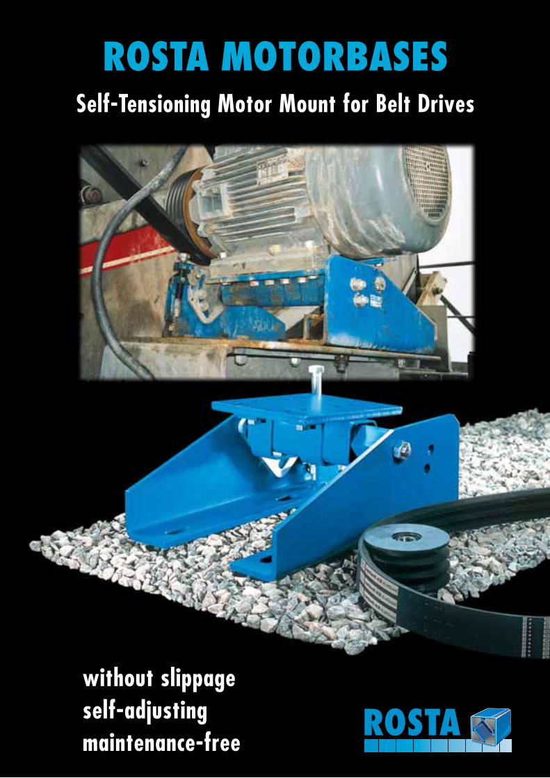
ROSTA MOTORBASES
without slippageself-adjustingmaintenance-free
Self-Tensioning Motor Mount for Belt Drives
ROSTA
ROSTATechnology
92
Mot
orba
ses
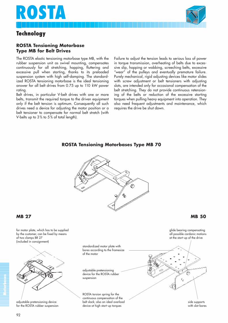
ROSTA Tensioning Motorbases Type MB 70
standardized motor plate withbores according to the framesizeof the motor
adjustable pretensioningdevice for the ROSTA rubbersuspension
ROSTA torsion spring for the continuous compensation of the
adjustable pretensioning device belt slack; also an ideal overload side supports for the ROSTA rubber suspension device at high start-up torques with slot-bores
MB 27 MB 50
glide bearing compensating all possible cardanic motionsat the start-up of the drive
for motor plate, which has to be suppliedby the customer, can be fixed by means of two clamps BR 27(included in consignment)
ROSTA Tensioning MotorbaseType MB for Belt Drives
The ROSTA elastic tensioning motorbase type MB, with therubber suspension unit as swivel mounting, compensatescontinuously for all stretching, hopping, fluttering andexcessive pull when starting, thanks to its preloadedsuspension system with high self-damping. The standard-ized ROSTA tensioning motorbase is the ideal tensioninganswer for all belt drives from 0.75 up to 110 kW powerrating.Belt drives, in particular V-belt drives with one or morebelts, transmit the required torque to the driven equipmentonly if the belt tension is optimum. Consequently all suchdrives need a device for adjusting the motor position or abelt tensioner to compensate for normal belt stretch (with V-belts up to 3 % to 5 % of total length).
Failure to adjust the tension leads to serious loss of powerin torque transmission, overheating of belts due to exces-sive slip, hopping or wobbing, screeching belts, excessive“wear” of the pulleys and eventually premature failure.Purely mechanical, rigid adjusting devices like motor slideswith screw adjustment or belt tensioners with adjustingslots, are intended only for occasional compensation of thebelt stretching. They do not provide continuous retension-ing of the belts or reduction of the excessive startingtorques when pulling heavy equipment into operation. Theyalso need frequent adjustments and maintenance, whichrequires the drive be shut down.
ROSTAROSTA
Mot
orba
ses
93
Technology
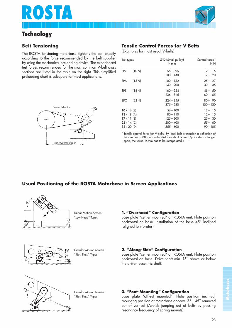
Belt Tensioning
The ROSTA tensioning motorbase tightens the belt exactlyaccording to the force recommended by the belt supplierby using the mechanical preloading device. The experiencedtest forces recommended for the most common V-belt crosssections are listed in the table on the right. This simplifiedpreloading chart is adequate for most applications.
Tensile-Control-Forces for V-Belts(Examples for most usual V-belts)
Belt types Ø D (Small pulley) Control force *in mm in N
SPZ (10 N) 56 – 95 12 – 15100 – 140 17 – 20
SPA (13 N) 100 – 132 25 – 27140 – 200 30 – 35
SPB (16 N) 160 – 224 45 – 50236 – 315 60 – 65
SPC (22 N) 224 – 355 80 – 90375 – 560 100 – 120
10 x 6 (Z) 56 – 100 12 – 1513 x 8 (A) 80 – 140 12 – 1517 x 11 (B) 125 – 200 25 – 3022 x 14 (C) 200 – 400 55 – 6032 x 20 (D) 355 – 600 90 – 105
* Tensile control force for V-belts. By ideal belt pretension a deflection of16 mm per 1000 mm center distance shall occur. (By shorter or longerspan, the value 16 mm has to be interpolated.)
16 mm deflection
per 1000 mm of span
F
ØD
Usual Positioning of the ROSTA Motorbase in Screen Applications
Linear Motion Screen 1. “Overhead” Configuration“Low Head” Types Base plate “center mounted” on ROSTA unit. Plate position
horizontal on base. Installation of the base 45° inclined(aligned to vibrator).
Circular Motion Screen 2. “Along-Side” Configuration“Ripl. Flow” Types Base plate “center mounted” on ROSTA unit. Plate position
horizontal on base. Drive shaft min. 15° above or belowthe driven eccentric shaft.
Circular Motion Screen 3. “Foot-Mounting” Configuration“Ripl. Flow” Types Base plate “off-set mounted”. Plate position inclined.
Mounting position of motorbase approx. 35 – 45° removedout of vertical (Avoids jumping out of belts by passingresonance frequency of spring mounts).
45°
15°
15°
35°– 45°
Mot
orba
ses
ROSTA
94
Technology
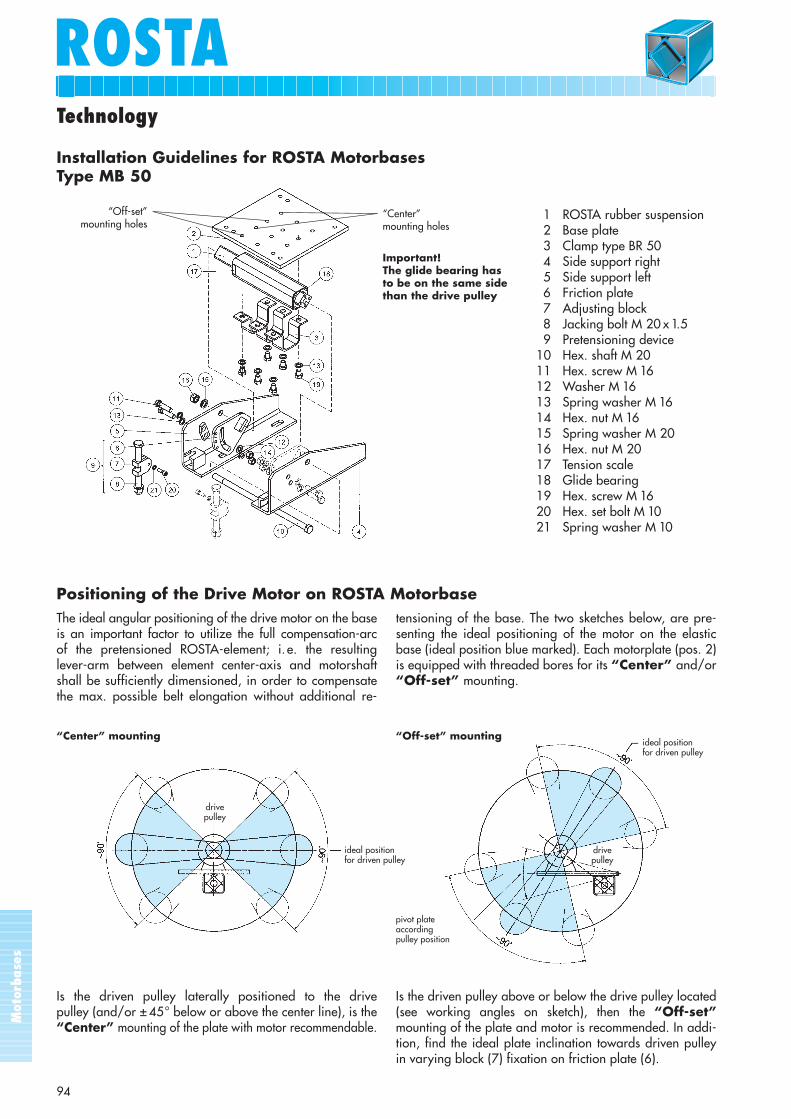
1 ROSTA rubber suspension2 Base plate3 Clamp type BR 504 Side support right5 Side support left6 Friction plate7 Adjusting block8 Jacking bolt M 20 x 1.59 Pretensioning device
10 Hex. shaft M 2011 Hex. screw M 1612 Washer M 1613 Spring washer M 1614 Hex. nut M 1615 Spring washer M 2016 Hex. nut M 2017 Tension scale18 Glide bearing19 Hex. screw M 1620 Hex. set bolt M 1021 Spring washer M 10
The ideal angular positioning of the drive motor on the baseis an important factor to utilize the full compensation-arc of the pretensioned ROSTA-element; i. e. the resulting lever-arm between element center-axis and motorshaftshall be sufficiently dimensioned, in order to compensatethe max. possible belt elongation without additional re-
Is the driven pulley laterally positioned to the drive pulley (and/or ± 45° below or above the center line), is the “Center” mounting of the plate with motor recommendable.
tensioning of the base. The two sketches below, are pre-senting the ideal positioning of the motor on the elasticbase (ideal position blue marked). Each motorplate (pos. 2)is equipped with threaded bores for its “Center” and/or“Off-set” mounting.
Important!The glide bearing has to be on the same sidethan the drive pulley
Installation Guidelines for ROSTA MotorbasesType MB 50
“Off-set”mounting holes
Is the driven pulley above or below the drive pulley located(see working angles on sketch), then the “Off-set”mounting of the plate and motor is recommended. In addi-tion, find the ideal plate inclination towards driven pulleyin varying block (7) fixation on friction plate (6).
“Off-set” mounting“Center” mountingideal positionfor driven pulley
ideal positionfor driven pulley
drivepulley
drivepulley
pivot plate accordingpulley position
“Center” mounting holes
Positioning of the Drive Motor on ROSTA Motorbase
Mot
orba
ses
ROSTAROSTA
9595
Technology
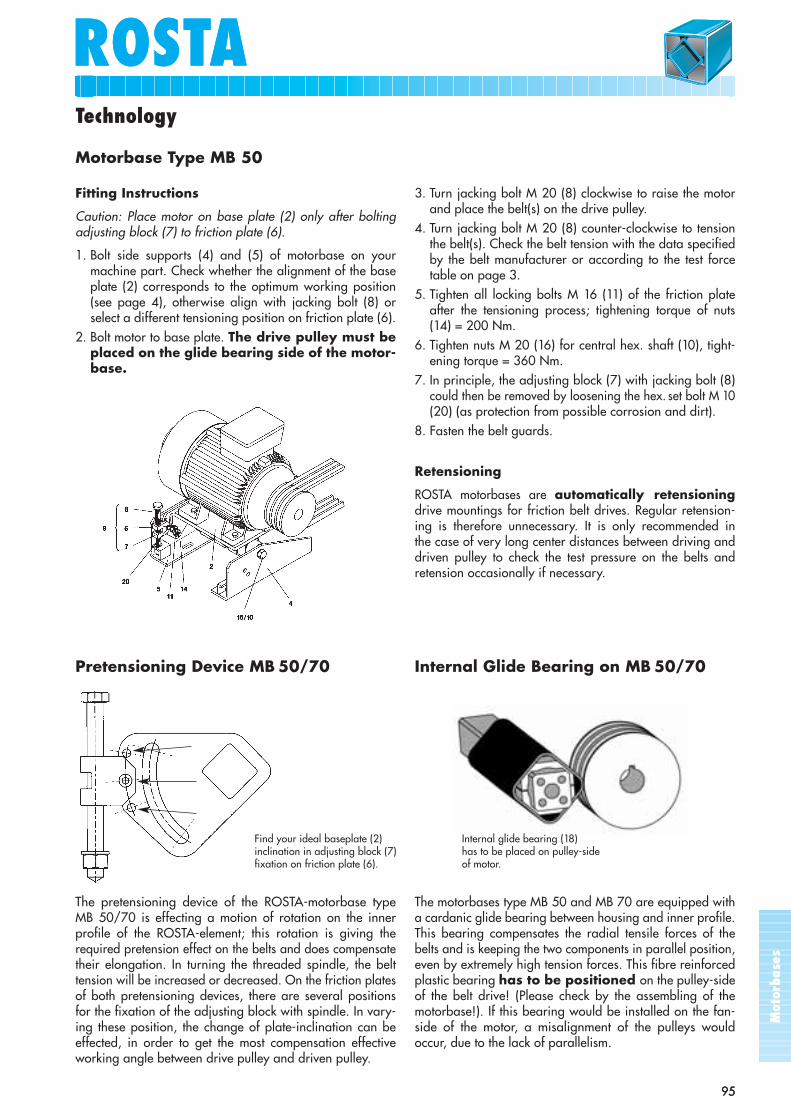
Fitting Instructions
Caution: Place motor on base plate (2) only after boltingadjusting block (7) to friction plate (6).
1. Bolt side supports (4) and (5) of motorbase on your machine part. Check whether the alignment of the baseplate (2) corresponds to the optimum working position(see page 4), otherwise align with jacking bolt (8) orselect a different tensioning position on friction plate (6).
2. Bolt motor to base plate. The drive pulley must beplaced on the glide bearing side of the motor-base.
3. Turn jacking bolt M 20 (8) clockwise to raise the motorand place the belt(s) on the drive pulley.
4. Turn jacking bolt M 20 (8) counter-clockwise to tensionthe belt(s). Check the belt tension with the data specifiedby the belt manufacturer or according to the test forcetable on page 3.
5. Tighten all locking bolts M 16 (11) of the friction plateafter the tensioning process; tightening torque of nuts(14) = 200 Nm.
6. Tighten nuts M 20 (16) for central hex. shaft (10), tight-ening torque = 360 Nm.
7. In principle, the adjusting block (7) with jacking bolt (8)could then be removed by loosening the hex. set bolt M 10(20) (as protection from possible corrosion and dirt).
8. Fasten the belt guards.
Retensioning
ROSTA motorbases are automatically retensioningdrive mountings for friction belt drives. Regular retension-ing is therefore unnecessary. It is only recommended in the case of very long center distances between driving anddriven pulley to check the test pressure on the belts andretension occasionally if necessary.
Motorbase Type MB 50
Pretensioning Device MB 50/70 Internal Glide Bearing on MB 50/70
The pretensioning device of the ROSTA-motorbase type MB 50/70 is effecting a motion of rotation on the innerprofile of the ROSTA-element; this rotation is giving therequired pretension effect on the belts and does compensatetheir elongation. In turning the threaded spindle, the belttension will be increased or decreased. On the friction platesof both pretensioning devices, there are several positionsfor the fixation of the adjusting block with spindle. In vary-ing these position, the change of plate-inclination can beeffected, in order to get the most compensation effectiveworking angle between drive pulley and driven pulley.
The motorbases type MB 50 and MB 70 are equipped witha cardanic glide bearing between housing and inner profile.This bearing compensates the radial tensile forces of thebelts and is keeping the two components in parallel position,even by extremely high tension forces. This fibre reinforcedplastic bearing has to be positioned on the pulley-sideof the belt drive! (Please check by the assembling of themotorbase!). If this bearing would be installed on the fan-side of the motor, a misalignment of the pulleys wouldoccur, due to the lack of parallelism.
Find your ideal baseplate (2)inclination in adjusting block (7)fixation on friction plate (6).
Internal glide bearing (18) has to be placed on pulley-side of motor.
Mot
orba
ses
ROSTA
96
Product Range
ROSTA Motorbase Type MB 27 Page 98
The ideal standardized motorbase for smaller belt driveswith electric motors from 0.75 to 4.0 kW (frame size di-mensions 90 S/L to 112 M). This base is delivered comple-tely assembled but without motor-plate, which has to besupplied by the customer. Thanks to its extremely compactoverall dimensions, the type MB 27 can be installed every-where without any major design changes. Therefore, theMB 27 is an ideal alternative to obsolete, non-automatictension rails. The pretensioning device with its left andright-hand thread gives a big positioning range offering anoptimum adaption of the working angle to the drivenpulley. All steel parts are painted with a blue primer.
ROSTA Motorbase Type MB 38 Page 99
The new ROSTA motorbase Type MB 38 for motor frame sizes from 132 S to 160 L (3 to 18.5 kW) is now avail-able on the drive component market – compact, operator-friendly, ready for immediate installation and cost-effective.Its new features are, above all, the price, the ready-to-install design and the simplest-possible installation proce-dure with the new pre-tensioning device.
With the new horizontal aligned finethread adjustingspindle, both the pre-tension and the necessary inclinationof the motor plate can be simply adjusted. The ready-to-useconstruction, the belt track adaptation and the fast clamp-ing system make the MB 38 absolutely revolutionary andextremely user-friendly in comparsion with alternative andpredecessor models! The frequently occurring “outside ap-plications” in screen drives, crushers and air conditioningsystems have been taken into account through the galvani-sation of the components.
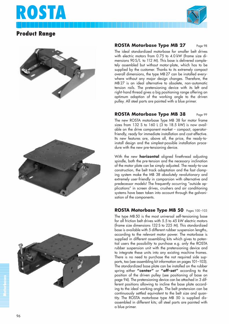
ROSTA Motorbase Type MB 50 Pages 100 –103
The type MB 50 is the most universal self-tensioning basefor all friction belt drives with 5.5 to 45 kW electric motors(frame size dimensions 132 S to 225 M). This standardizedbase is available with 5 different rubber suspension lengths,according to the relevant motor power. The motorbase issupplied in different assembling kits which gives to poten-tial users the possibility to purchase e.g. only the ROSTArubber suspension unit with the pretensioning device andto integrate these units into any existing machine frames.There is no need to purchase the not required side sup-ports, too (see assembling kit information on pages 101–103).The standardized base plate can be installed on the rubberspring either “center” or “off-set” according to the position of the driven pulley (see positioning of base onpage 94). The pretensioning device can be attached in 3 dif-ferent positions allowing to incline the base plate accord-ing to the ideal working angle. The belt pretension can becontinuously settled equivalent to the belt size and quan-tity. The ROSTA motorbase type MB 50 is supplied dis-assembled in different kits; all steel parts are painted witha blue primer.
Mot
orba
ses
ROSTAROSTA
97
Product Range
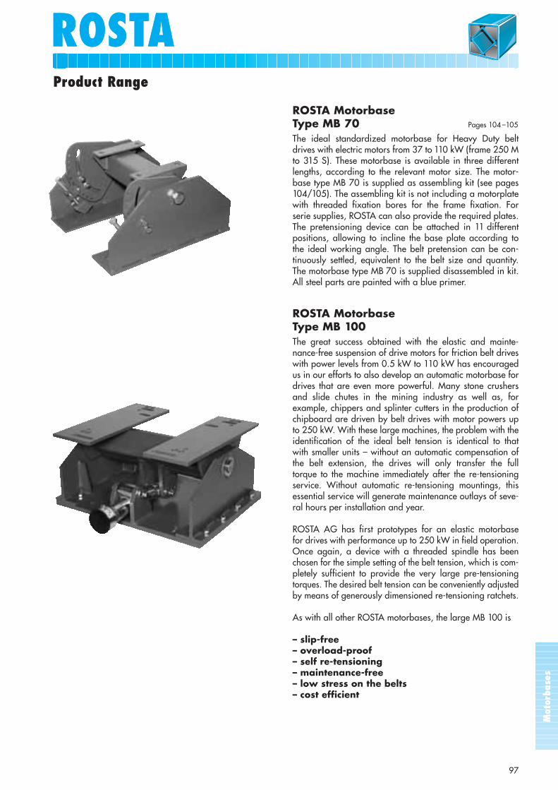
ROSTA Motorbase Type MB 70 Pages 104 –105
The ideal standardized motorbase for Heavy Duty beltdrives with electric motors from 37 to 110 kW (frame 250 Mto 315 S). These motorbase is available in three differentlengths, according to the relevant motor size. The motor-base type MB 70 is supplied as assembling kit (see pages104/105). The assembling kit is not including a motorplatewith threaded fixation bores for the frame fixation. Forserie supplies, ROSTA can also provide the required plates.The pretensioning device can be attached in 11 differentpositions, allowing to incline the base plate according tothe ideal working angle. The belt pretension can be con-tinuously settled, equivalent to the belt size and quantity.The motorbase type MB 70 is supplied disassembled in kit.All steel parts are painted with a blue primer.
ROSTA MotorbaseType MB 100The great success obtained with the elastic and mainte-nance-free suspension of drive motors for friction belt driveswith power levels from 0.5 kW to 110 kW has encouragedus in our efforts to also develop an automatic motorbase fordrives that are even more powerful. Many stone crushersand slide chutes in the mining industry as well as, for example, chippers and splinter cutters in the production ofchipboard are driven by belt drives with motor powers upto 250 kW. With these large machines, the problem with theidentification of the ideal belt tension is identical to thatwith smaller units – without an automatic compensation ofthe belt extension, the drives will only transfer the full torque to the machine immediately after the re-tensioningservice. Without automatic re-tensioning mountings, thisessential service will generate maintenance outlays of seve-ral hours per installation and year.
ROSTA AG has first prototypes for an elastic motorbase for drives with performance up to 250 kW in field operation.Once again, a device with a threaded spindle has beenchosen for the simple setting of the belt tension, which is com-pletely sufficient to provide the very large pre-tensioningtorques. The desired belt tension can be conveniently adjustedby means of generously dimensioned re-tensioning ratchets.
As with all other ROSTA motorbases, the large MB 100 is
– slip-free– overload-proof– self re-tensioning– maintenance-free– low stress on the belts– cost efficient
Mot
orba
ses
ROSTA
98
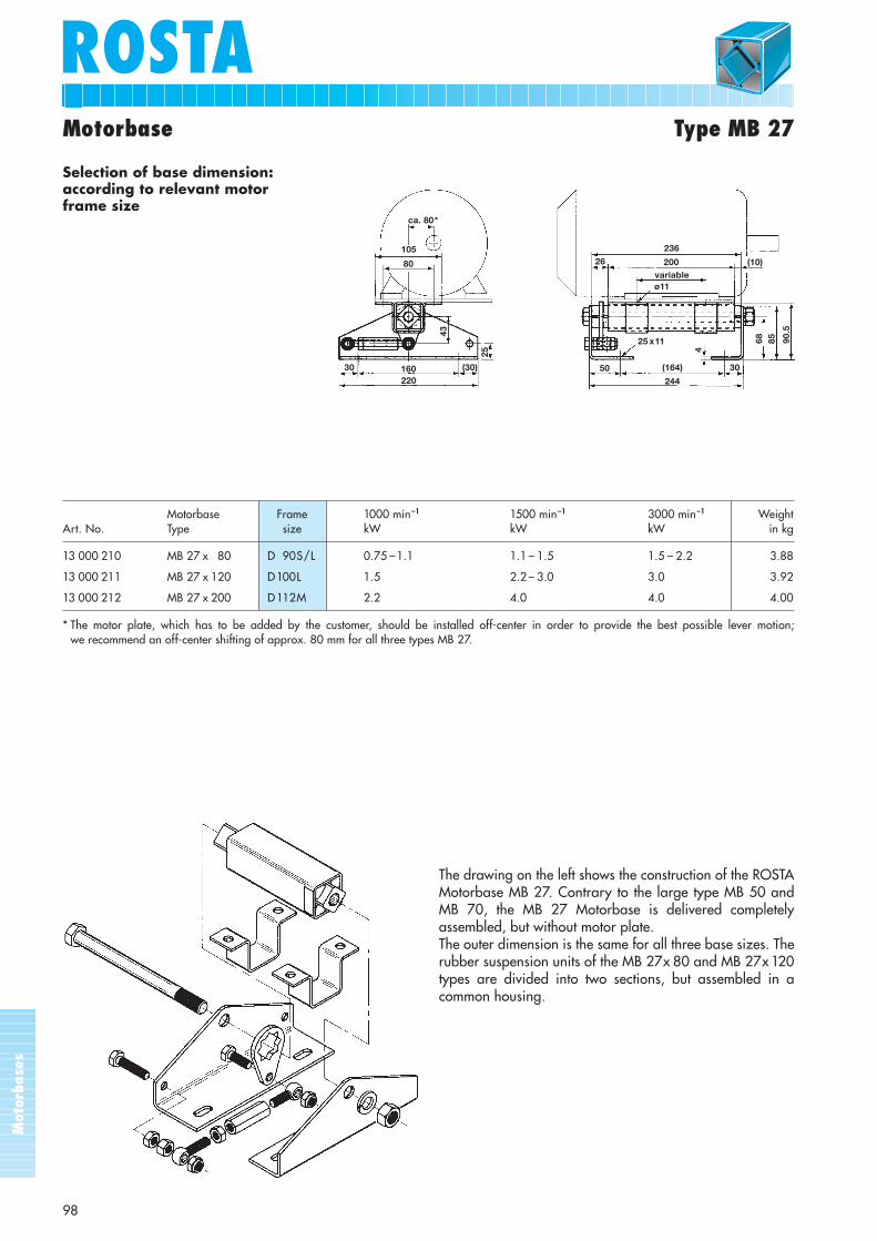
Motorbase Type MB 27
Selection of base dimension:according to relevant motor frame size
Motorbase Frame 1000 min–1 1500 min–1 3000 min–1 WeightArt. No. Type size kW kW kW in kg
13 000 210 MB 27 x 80 D 90S/L 0.75 –1.1 1.1 – 1.5 1.5 – 2.2 3.88
13 000 211 MB 27 x 120 D100L 1.5 2.2 – 3.0 3.0 3.92
13 000 212 MB 27 x 200 D112M 2.2 4.0 4.0 4.00
* The motor plate, which has to be added by the customer, should be installed off-center in order to provide the best possible lever motion; we recommend an off-center shifting of approx. 80 mm for all three types MB 27.
The drawing on the left shows the construction of the ROSTAMotorbase MB 27. Contrary to the large type MB 50 andMB 70, the MB 27 Motorbase is delivered completelyassembled, but without motor plate.The outer dimension is the same for all three base sizes. Therubber suspension units of the MB 27x 80 and MB 27x 120types are divided into two sections, but assembled in acommon housing.
ca. 80*
105
43
(30)
25
80
22016030
236
200variable
(10)
ø11
26
3050
25 x11
(164)
244
4
90.5
8568
Mot
orba
ses
ROSTAROSTA
99
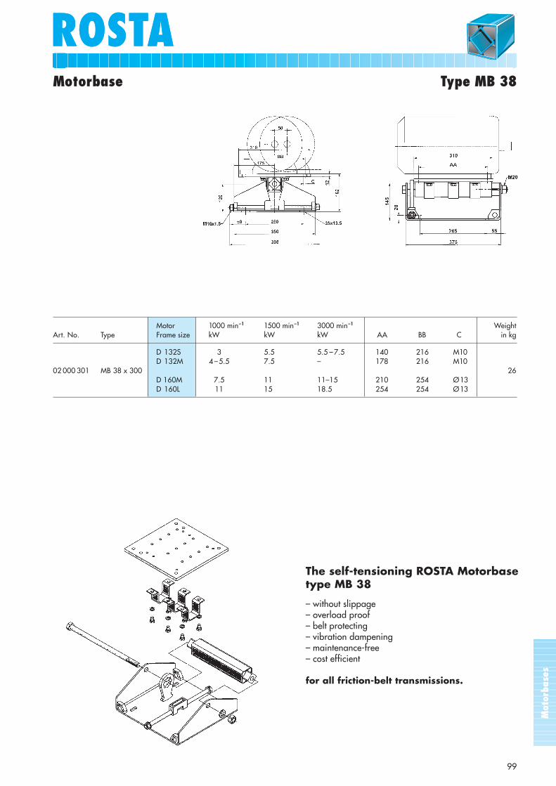
Motor 1000 min–1 1500 min–1 3000 min–1 WeightArt. No. Type Frame size kW kW kW AA BB C in kg
D 132S 3 5.5 5.5 – 7.5 140 216 M10D 132M 4 –5.5 7.5 – 178 216 M10
02 000 301 MB 38 x 300 26D 160M 7.5 11 11–15 210 254 Ø13D 160L 11 15 18.5 254 254 Ø13
Motorbase Type MB 38
The self-tensioning ROSTA Motorbase type MB 38
– without slippage– overload proof– belt protecting– vibration dampening– maintenance-free– cost efficient
for all friction-belt transmissions.
Mot
orba
ses
100
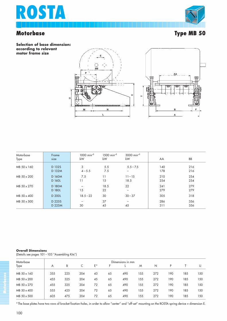
ROSTAMotorbase Type MB 50
Overall Dimensions(Details see pages 101 – 103 “Assembling Kits”)
Motorbase Dimensions in mmType A B C E* F L M N P T U
MB 50 x 160 355 225 204 43 65 490 155 272 190 185 150
MB 50 x 200 455 325 204 45 65 490 155 272 190 185 150
MB 50 x 270 455 325 204 72 65 490 155 272 190 185 150
MB 50 x 400 555 425 204 72 65 490 155 272 190 185 150
MB 50 x 500 605 475 204 72 65 490 155 272 190 185 150
* The base plates have two rows of bracket fixation-holes, in order to allow “center” and “off-set” mounting on the ROSTA spring device = dimension E.
Motorbase Frame 1000 min–1 1500 min–1 3000 min–1
Type size kW kW kW AA BB
MB 50 x 160 D 132S 3 5.5 5.5 – 7.5 140 216D 132M 4 – 5.5 7.5 – 178 216
MB 50 x 200 D 160M 7.5 11 11– 15 210 254D 160L 11 15 18.5 254 254
MB 50 x 270 D 180M – 18.5 22 241 279D 180L 15 22 – 279 279
MB 50 x 400 D 200L 18.5 – 22 30 30 – 37 305 318
MB 50 x 500 D 225S – 37 – 286 356D 225M 30 45 45 311 356
Selection of base dimension:according to relevantmotor frame size
E
BB
P
U
M N
L
C T
A
B F
AA
Mot
orba
ses
101
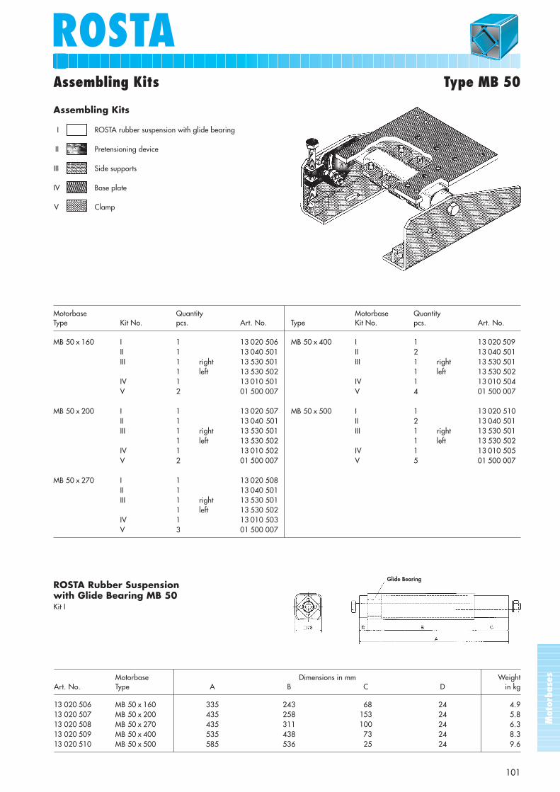
ROSTAAssembling Kits Type MB 50
Assembling Kits
I ROSTA rubber suspension with glide bearing
II Pretensioning device
III Side supports
IV Base plate
V Clamp
Motorbase Quantity Motorbase QuantityType Kit No. pcs. Art. No. Type Kit No. pcs. Art. No.
MB 50 x 160 I 1 13 020 506 MB 50 x 400 I 1 13 020 509II 1 13 040 501 II 2 13 040 501III 1 right 13 530 501 III 1 right 13 530 501
1 left 13 530 502 1 left 13 530 502IV 1 13 010 501 IV 1 13 010 504V 2 01 500 007 V 4 01 500 007
MB 50 x 200 I 1 13 020 507 MB 50 x 500 I 1 13 020 510II 1 13 040 501 II 2 13 040 501III 1 right 13 530 501 III 1 right 13 530 501
1 left 13 530 502 1 left 13 530 502IV 1 13 010 502 IV 1 13 010 505V 2 01 500 007 V 5 01 500 007
MB 50 x 270 I 1 13 020 508II 1 13 040 501III 1 right 13 530 501
1 left 13 530 502IV 1 13 010 503V 3 01 500 007
ROSTA Rubber Suspension with Glide Bearing MB 50Kit I
Motorbase WeightArt. No. Type A B C D in kg
13 020 506 MB 50 x 160 335 243 68 24 4.913 020 507 MB 50 x 200 435 258 153 24 5.813 020 508 MB 50 x 270 435 311 100 24 6.313 020 509 MB 50 x 400 535 438 73 24 8.313 020 510 MB 50 x 500 585 536 25 24 9.6
Dimensions in mm
Glide Bearing

Mot
orba
ses
ROSTA
102
Assembling Kits Type MB 50
WeightArt. No. Marking A B C in kg
13 040 501 Pretensioning Device to MB 50 100 130 220 2.72
Pretensioning Device to MB 50Kit II
Side Support to MB 50Kit III
WeightArt. No. Marking in kg
13 530 501 Side Support to MB 50 right Details according drawing 9.3413 530 502 Side Support to MB 50 left Details mirror inverted to drawing 9.34
Dimensions in mm
B
A
C
190
Ø 18Ø 22
150
27263
54 x 22
490
23
32
185
R 100
20°
10°
10 12
50
50
27
65
22
100
Mot
orba
ses
ROSTAROSTA
103
Assembling Kits Type MB 50
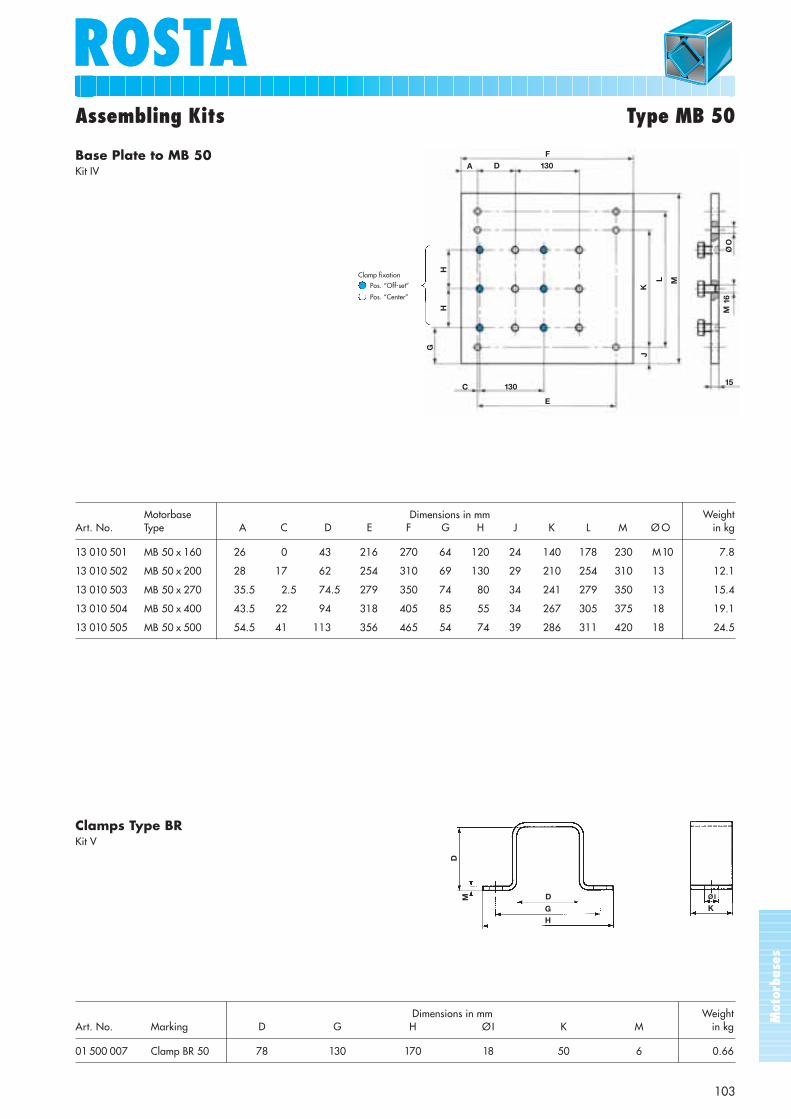
Base Plate to MB 50Kit IV
Clamps Type BRKit V
WeightArt. No. Marking D G H ØI K M in kg
01 500 007 Clamp BR 50 78 130 170 18 50 6 0.66
Dimensions in mm
D
GH
DM
K
ØI
F
A D 130
HH
G
130
E
ML
KJ
ØO
M 1
6
15
Clamp fixation
Pos. “Off-set”
Pos. “Center”
C
Motorbase WeightArt. No. Type A C D E F G H J K L M Ø O in kg
13 010 501 MB 50 x 160 26 0 43 216 270 64 120 24 140 178 230 M10 7.8
13 010 502 MB 50 x 200 28 17 62 254 310 69 130 29 210 254 310 13 12.1
13 010 503 MB 50 x 270 35.5 2.5 74.5 279 350 74 80 34 241 279 350 13 15.4
13 010 504 MB 50 x 400 43.5 22 94 318 405 85 55 34 267 305 375 18 19.1
13 010 505 MB 50 x 500 54.5 41 113 356 465 54 74 39 286 311 420 18 24.5
Dimensions in mm
Mot
orba
ses
104
ROSTA
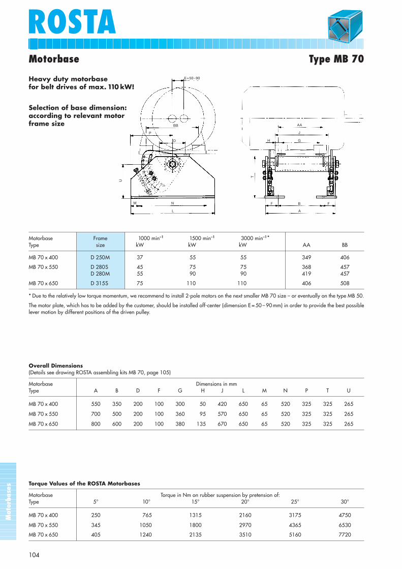
Motorbase Frame 1000 min–1 1500 min–1 3000 min–1*Type size kW kW kW AA BB
MB 70 x 400 D 250M 37 55 55 349 406
MB 70 x 550 D 280S 45 75 75 368 457D 280M 55 90 90 419 457
MB 70 x 650 D 315S 75 110 110 406 508
* Due to the relatively low torque momentum, we recommend to install 2-pole motors on the next smaller MB 70 size – or eventually on the type MB 50.
The motor plate, which has to be added by the customer, should be installed off-center (dimension E = 50 – 90 mm) in order to provide the best possiblelever motion by different positions of the driven pulley.
Overall Dimensions(Details see drawing ROSTA assembling kits MB 70, page 105)
Motorbase Dimensions in mmType A B D F G H J L M N P T U
MB 70 x 400 550 350 200 100 300 50 420 650 65 520 325 325 265
MB 70 x 550 700 500 200 100 360 95 570 650 65 520 325 325 265
MB 70 x 650 800 600 200 100 380 135 670 650 65 520 325 325 265
Torque Values of the ROSTA Motorbases
Motorbase Torque in Nm on rubber suspension by pretension of:Type 5° 10° 15° 20° 25° 30°
MB 70 x 400 250 765 1315 2160 3175 4750
MB 70 x 550 345 1050 1800 2970 4365 6530
MB 70 x 650 405 1240 2135 3510 5160 7720
E = 50 – 90
BB
P
D
U
M N
L
AA
G
J
H
T
F B
A
F
Motorbase Type MB 70
Heavy duty motorbase for belt drives of max. 110 kW!
Selection of base dimension:according to relevant motorframe size
Mot
orba
ses
105
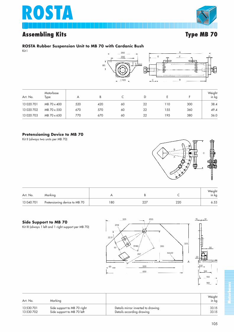
ROSTAAssembling Kits Type MB 70
ROSTA Rubber Suspension Unit to MB 70 with Cardanic BushKit I
Pretensioning Device to MB 70Kit II (always two units per MB 70)
Side Support to MB 70Kit III (always 1 left and 1 right support per MB 70)
260
200
Ø2280
�120
B
A
C
22.5°
15°
65 520
650
267
R180
325
Ø18
265325
Ø33
54x22
Motorbase WeightArt. No. Type A B C D E F in kg
13 020 701 MB 70 x 400 520 420 60 22 110 300 38.4
13 020 702 MB 70 x 550 670 570 60 22 155 360 49.4
13 020 703 MB 70 x 650 770 670 60 22 195 380 56.0
WeightArt. No. Marking A B C in kg
13 040 701 Pretensioning device to MB 70 180 227 220 6.53
D
A
FE
C B
1215
50
22
32
100
150
160
WeightArt. No. Marking in kg
13 530 701 Side support to MB 70 right Details mirror inverted to drawing 33.1513 530 702 Side support to MB 70 left Details according drawing 33.15

Mot
orba
ses
ROSTA
106
Applications
MB 50 on punching press MB 50 with drive motor for exciter
MB 50 for belt drive on circular motion screen
MB 50 with drives for roller mills MB 70 with drive for marble saw
MB 70 with variable speed drive for crusher
Mot
orba
ses
ROSTAROSTA
107
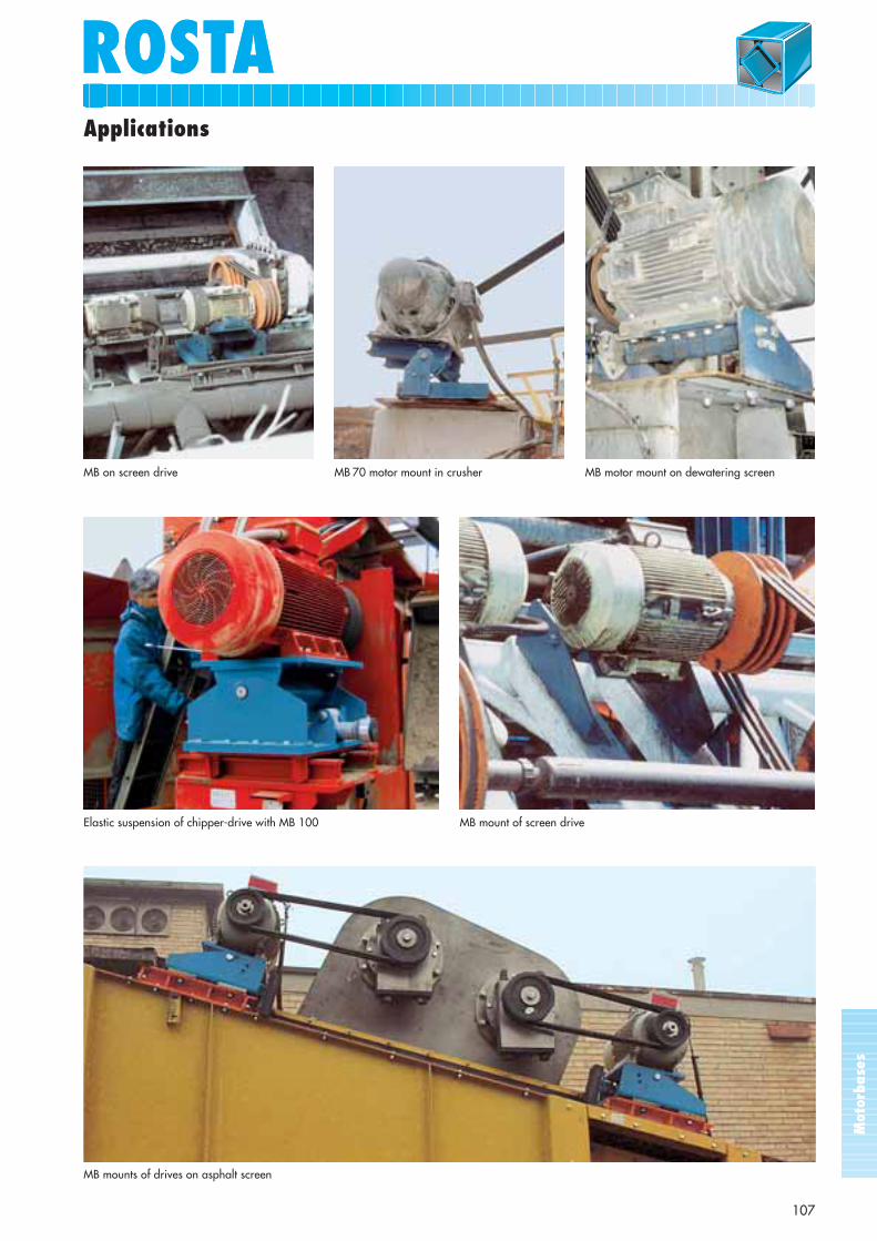
Applications
Elastic suspension of chipper-drive with MB 100 MB mount of screen drive
MB on screen drive MB 70 motor mount in crusher MB motor mount on dewatering screen
MB mounts of drives on asphalt screen
ROSTASector Exploitation
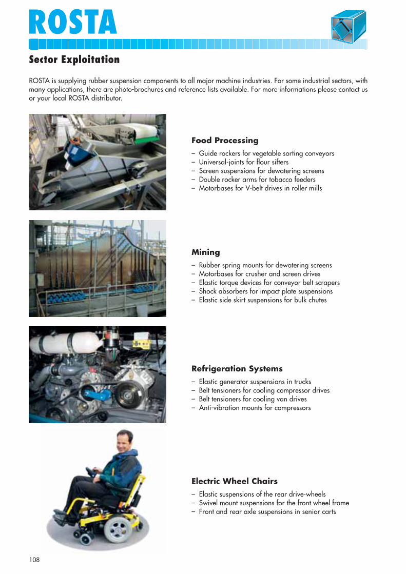
Food Processing– Guide rockers for vegetable sorting conveyors– Universal-joints for flour sifters– Screen suspensions for dewatering screens– Double rocker arms for tobacco feeders– Motorbases for V-belt drives in roller mills
Mining– Rubber spring mounts for dewatering screens– Motorbases for crusher and screen drives– Elastic torque devices for conveyor belt scrapers– Shock absorbers for impact plate suspensions– Elastic side skirt suspensions for bulk chutes
Refrigeration Systems– Elastic generator suspensions in trucks – Belt tensioners for cooling compressor drives– Belt tensioners for cooling van drives– Anti-vibration mounts for compressors
ROSTA is supplying rubber suspension components to all major machine industries. For some industrial sectors, withmany applications, there are photo-brochures and reference lists available. For more informations please contact usor your local ROSTA distributor.
Electric Wheel Chairs– Elastic suspensions of the rear drive-wheels– Swivel mount suspensions for the front wheel frame– Front and rear axle suspensions in senior carts
108

ROSTA
109
Sector Exploitation
Farming– Universal tensioners for all chain drives– Universal tensioners for all belt drives– Rocker arms for screens in combines– Suspensions for selection arms in potato harvesters– Elastic bearings for seed sledges– Stabilizers for irrigation beams
Rail– Elastic collector suspensions in pantographs– Rail collector suspensions for subway locomotives– Resilient mountings for floating compartments– Support springs for pressurized coach connections– Shock absorbing mounts for rail bed compactors
Road Maintenance– Elastic suspensions of snow ploughs– Elastic blade suspension for scraper tips– Flexible rotary brush suspensions– Belt tensioners for vacuum cyclone drives– Elastic suspensions of rubber sweeping skirts
Wood Processing– Adjustable rocker arms for chip shakers– Universal joints for gyrator sifting screens– Impact plate suspensions for log stops– Guide roller suspensions for milling/grinding machines– Suspensions for timber waste feeders
Some Useful Informations
ROSTA4. Technical GuidelinesPlease respect the capacity limits of the ROSTA elements,mentioned in this catalogue (load limits, frequency limits,angles of oscillation etc.). In doubt, please contact us orone of our representatives (see list on last page of this cata-logue). Please follow carefully our mounting instructions forthe different elements. Please make sure, that the mountingpersonal does follow these guidelines, too. Our elements are usually supplied without the fixationscrews for the final positioning on your machine part.Please use the size of screw fitting exactly the bores sizeson our fixation brackets and clamps, in quality 8.8.Concerning the required fixation torque of these screws,please consult the ISO-guidelines 898, or contact your sup-plier of the screws. Please make sure, that the fixation scr-ews are also equipped with stop- or lock-washers. Finally,please check, that the screw connections are made accord-ing to the VDI-guidelines 2230.For the fixation of machine components/parts withoutmachined bore holes (cast parts, e.g. the brackets of theAB 50 elements) or parts with oblong holes (e.g. supportsof the motorbases) please use additional washers accord-ing DIN 125 B.
5. QualificationsThis printed matter and all other technical data are forinformation only, without contractual engagement. Ourproducts must be processed and applied according to theirpurpose and the ruling conditions. No part of this publication may be reproduced by anymeans without the written permission of the publisher.
1. Customer Service and OffersWhenever you have a problem and need assistance pleasecontact your local ROSTA representative (see list on backpage of catalogue) which will help you at any time.In order to prepare precise offers we need comprehensivetechnical data on your installations and systems, possiblyincluding sketches and specification sheets. These will helpus to find the most cost-effective solution for you, either onthe basis of standard parts or special customised elements.We will give you a questionnaire to better specify yourrequirements in case you need more specific elements.Our delivery conditions and terms of payment are indi-cated on our offers.
2. Orders and DeliveryPlease indicate the quotation number (if existing) on yourorder form, the exact number of items including the de-scription of the article as well as the article number. Pleasesend your orders to your local representative.
3. Availability of Our ProductsMost of the standard elements shown in this catalogue areavailable from stock, either delivered by one of our repre-sentatives or by ROSTA.Special elements are produced custom-made and thereforetake some time to be delivered. However, if you enter acontract to purchase our products regularly, the deliverytime may be considerably reduced. Please contact us aboutthis matter.
110

ROSTAROSTANotes

Your ROSTA Partner – Worldwide!
ROSTA AGCH - 5502 HunzenschwilPhone +41 (0)62 897 24 21Fax +41 (0)62 897 15 10E-Mail [email protected] www.rosta.ch
ARGENTINA:ENRIQUE HEUCHERTAR-1879 Quilmes Oeste/Buenos Aires
AUSTRALIA:CRUSHING & MININGEQUIPMENT Pty. Ltd.AU-Naval Base W.A. 6165
BRAZIL :A.T. I. BrasilBR-81030-000 Curitiba
DENMARK:JENS S. Transmissioner A/SDK-2635 Ishøj
GERMANY:ROSTA GmbHDE-58332 Schwelm
GREAT BRITAIN:KOBO (UK) Ltd.HandforthGB-Cheshire SK9 3HW
F INLAND: LEKTAR OYSF-00701 Helsinki
FRANCE: PRUD’HOMME TransmissionsFR-93203 Saint Denis
CANADA: ROSTA Inc.CA-Uxbridge, Ontario L9P 1S9
SPAIN:TRACSA S.L.ES-08015 Barcelona
GREECE:GEORG P. ALEXANDRIS S.A.GR-185 45 Piraeus
NEW ZEALAND: SAECOBearing & TransmissionNZ-Auckland
SOUTH AFRICA:Orange Vibrator MotorCo. Pty. Ltd.ZA-0017 Doornpoort/Pretoria
NETHERLANDS:Mijnsbergen BVNL-3640 AD Mijdrecht
BELGIUM/LUXEMBURG:ATB n.v.BE-1600 Sint-Pieters-Leeuw
NORWAY:JENS S. Transmisjoner A/SNO-0612 Oslo
SOUTH KOREA:SEWON Industrial Ltd.KR-Seoul
IRELAND: MODERN PLANT Ltd.IE-Clondalkin, Dublin 22
AUSTRIA: HABERKORN Ulmer GmbHAT-6961 Wolfurt
THAILAND:VIRTUS Company Ltd.TH-10600 Bangkok
ICELAND:FALKINN Ltd.IS-128 Reykjavik
POLAND:Archimedes sp.z.o.o.PL-87-100 Torún
CZECHIA:RUPET Int. s.r.o.CZ-25301 Hostivice
SWEDEN: KONTIMA ABSE-14901 Nynaeshamn
I TALY: ROSTA S.r.l.IT-20020 Lainate Milano
SINGAPORE & MALAYSIA:SM ComponentRS-128384 Singapore
USA:LOVEJOY Inc.US-Downers GroveIllinois 60515
JAPAN: MIKI PULLEY Co. Ltd.JP-Zama-City, Kanagawa
SLOWAKIA: RUPET Int. s.r.o.SK-92101 Piestany
T200
7.71
1
CHILE :Riosan Cia. Ltda.CL-Concepción
CHINA:Shanghai Miki PulleyIntern. Trading Co. Ltd.CN-200040 Shanghai
INDIA:TechnotalentIN-560058 Bangalore
ISRAEL :Ledico Ltd.IL-75654 Rishon le Zion
HUNGARY:Feming Kft.HU-1027 Budapest
TURKEY:Entatek Industry Ltd.TR-81260 Umraniye/Istanbul
PERU:DucassePE-Miraflores
PORTUGAL: April Ltda.PT-1514-801 Lisboa
RUSSIA:FAM Machinery Components PartsRU-199178 St. Petersburg