Embed Size (px)
Citation preview
See discussions, stats, and author profiles for this publication at: https://www.researchgate.net/publication/307914416
ROS+unity: An efficient high-fidelity 3D multi-UAV navigation and control
simulator in GPS-denied environments
Conference Paper in SIMULATION: Transactions of The Society for Modeling and Simulation International · November 2015
DOI: 10.1109/IECON.2015.7392488
CITATIONS
3
READS
1,230
5 authors, including:
Some of the authors of this publication are also working on these related projects:
Autonomy of Single UAV View project
Modeling and Control of Unmanned Aerial Vehicles View project
Wei Meng
National University of Singapore
33 PUBLICATIONS 325 CITATIONS
SEE PROFILE
Yuchao Hu
National University of Singapore
7 PUBLICATIONS 16 CITATIONS
SEE PROFILE
Feng Lin
National University of Singapore
66 PUBLICATIONS 365 CITATIONS
SEE PROFILE
Rodney Teo
National University of Singapore
33 PUBLICATIONS 752 CITATIONS
SEE PROFILE
All content following this page was uploaded by Wei Meng on 11 February 2017.
The user has requested enhancement of the downloaded file.
Applications
Simulation
Simulation: Transactions of the Society for
Modeling and Simulation International
2016, Vol. 92(10) 931–944
� The Author(s) 2016
DOI: 10.1177/0037549716666683
sim.sagepub.com
ROSUnitySim: Development andexperimentation of a real-timesimulator for multi-unmanned aerialvehicle local planning
Yuchao Hu and Wei Meng
AbstractIn this paper, we present a novel real-time three-dimensional simulation system, ROSUnitySim, for local planning by min-iature unmanned aerial vehicles (UAVs) in cluttered environments. Unlike commonly used simulation systems in roboticresearch—e.g., USARSim, Gazebo, etc.—in this work our development is based on a robot operation system (ROS) andwith a different game engine, Unity3D. Compared with Unreal Engine, which is used in USARSim, Unity3D is much eas-ier for entry level developers and has more users in the industry. On the other hand, as we know, ROS can provide aclear software structure and simultaneous operation between hardware devices for actual UAVs. By developing a datatransmitting interface, a communication module and detailed environment and sensor modeling techniques, we have suc-cessfully glued ROS and Unity3D together for real-time UAV simulations. Another key point of our work is that we pro-pose an efficient multi-UAV simulation structure and successfully simulate multiple UAVs, which is a challenging task,running 40Hz LIDAR (Light detection and ranging) sensing and communications in complex environments. The simulatorstructure is almost the same as real flight tests. Hence, by using the developed simulation system, we can easily verifydevelop flight control and navigation algorithms and save substantial effort in flight tests.
KeywordsUnity3D, simulator, unmanned aerial vehicle, navigation, guidance, robot operating system
1 Introduction
Recently, small-scale unmanned aerial vehicles (UAVs)
have attracted great interest and attention from academic
research groups worldwide because of their great potential
in both military and civil applications. Many groups have
constructed their own UAV platforms.1–6 Especially, navi-
gation and guidance of UAVs in GPS-denied environ-
ments is still a challenging task.7 Nevertheless, generally
speaking, the implementation of UAVs is costly and time-
consuming. Simulation technologies have been widely
used by academic research as a cost-effective way to
accelerate processing procedures. They are especially
important in the case of UAV development due to the
complexity involved in outdoor environments and network
communications. Therefore, simulation is an effective way
to detect and prevent unnecessary malfunctions of hard-
ware, software and automatic flight control systems.1
Simulation technologies can provide great help to ver-
ify the algorithms and identify potential problems before
flight tests and to make physical implementation smooth
and successful.8,9 Some well-known recent works have
demonstrated the capabilities of three-dimensional (3D)
simulations, such as OpenSim,10 the Virtual robot experi-
mentation platform (V-REP),11 Delta3D,12 USARSim,13
and Gazebo,14 etc. OpenSim is one of the earliest attempts,
in 2001, at a 3D robotic simulator. It is a 3D simulator for
autonomous robots that uses OpenGL for real-time render-
ing of the robot environment. But the development is no
longer active since October 2008 and also it is not good at
real-time rendering of robot environments. V-REP is a
commercial product and not open-source.11 Gazebo is a
mature and good open-source simulator but it is developed
and supported mostly on Linux and not meant for hybrid
simulation.14 To further address the challenges of hybrid
simulation, the unified system for automation and robotics
simulator (USARSim), a high-fidelity simulation tool
Temasek Laboratories, National University of Singapore
Corresponding author:
Wei Meng, Temasek Laboratories, T-Lab Building, 5A, Engineering Drive
1, Singapore 117411.
Email: [email protected]
at NATIONAL UNIV SINGAPORE on October 11, 2016sim.sagepub.comDownloaded from
based on Unreal technology, gained more researchers’
attention, as it represents robot automation and behavior,
and also renders user interface elements precisely.13
However, USARSim-based simulation tools have not been
updated regularly recently. According to our experience,
the available simulation systems are not suitable for multi-
UAV real-time tests, especially when the 3D environments
are large-scale and complex. As you can see, there are
many 3D simulators already available. So, why do we still
need to develop a new UAV simulation system? The main
reason is that most open-source simulation systems find it
difficult to handle multiple UAVs simultaneously, sensing
in complex and high fidelity environments. In addition, it
is hard to modify the developments in USARSim. Another
reason is that, for industrial applications, it is required to
develop a complete simulation system, including environ-
ment sensing modeling, flight control and navigation algo-
rithms. The UAVs are expected to cooperatively and
autonomously operate in GPS-denied foliage or urban
environments. The LIDAR-based simultaneous localiza-
tion and mapping (SLAM) algorithm needs to be simu-
lated in real-time. According to our knowledge, most
simulation systems are not ‘‘real’’ enough. Firstly, the
environments—especially, the collision level of the trees
and buildings—needs to be modeled as realistically as pos-
sible. Secondly, UAV sensors, such as LIDAR and cam-
eras, are required to be modeled as real and need to run in
a high-frequency level in a dense and harsh environment.
In this paper, a novel hybrid 3D simulator is developed
based on robot operating system (ROS) and a game
engine, Unity3D. ROS15 is an open-source framework
designed to provide an abstraction layer to complex
robotic hardware and software configurations. It provides
libraries and tools to help software developers create robot
applications and has found wide use in both industry and
academia. Gazebo, which was mentioned above, also ori-
ginates from ROS. Unity3D is a more flexible and power-
ful development platform for creating multiplatform 3D
and two-dimensional (2D) games and interactive experi-
ences. This game engine, which supports almost every
platform, is chosen to be the simulation server. Besides
game developments, Unity3D could also be employed by
academic research.16 It has been developed as a simulator
in geographic information systems,17 the communication
system for Moon base simulated scenarios, and wind
energy development.18 These implications prove that
Unity3D can also be used in academic area with vivid and
highly interactive performance. The main reason of choos-
ing Unity3D as the visualization tool is that it is easier for
entry-level researchers to develop their UAV applications,
especially, to build real-time sensor models, physical mod-
els, etc. In addition, since the programing language for
Unity3D is C#, it is easier for the researchers to under-
stand and develop further.
The main contribution of this paper is that we have
developed an application driven multi-UAV simulator
based on ROS and Unity3D. To the best of our knowledge,
our work is the first to involve the Unity3D technique in
UAV sensing and planning simulation research. We focus
particualarly on a novel and effective way to simulate mul-
tiple UAVs simultaneously. In our work, the interface
between ROS and Unity3D has been developed based on
the TCP/IP protocol. The LIDAR sensor is one of the most
popular sensors used in GPS-denied environments. In this
work, we focus on sensor modeling and local planning in
GPS-denied environments. GPS does not function per-
fectly with our simulator. The key component for the
SLAM algorithm is modeled in detail in the Unity3D
script. Environment modeling—including trees, terrain,
buildings, etc.—is also developed and will be introduced
in our simulation technique section. The preliminary ver-
sion of our simulator was presented in Meng et al.19 In this
earlier work, we gave a brief description of the structure of
the simulator: ROSUnitySim. In the current version of the
work, we have made extensive extensions and new contri-
butions: (1) The structure of the simulator has been
improved to support efficient multi-UAV simulations.
(2) Detailed technical issues, such as the communication
protocol, client/server structure, the interface between
ROS and Unity3D, have been added. (3) Performance
analysis of the simulator has been provided. (4) More
experiment results and analysis have been included to ver-
ify the efficiency and success of the simulator.
The remainder of the paper is organized as follows. The
main structure of the developed ROSUnitySim is stated in
Section 2. Some key technical issues involved are pre-
sented in Section 3. Simulator performance analysis is
addressed in 4. In Section 5, both simulation results and
flight test results have been reported. Section 6 addresses
the impact of our work. Section 7 concludes the paper.
2 ROSUnitySim development
Before going on to illustrate the detailed techniques in our
developed ROSUnitySim, the structure of the simulator is
briefly introduced. As addressed above, in this work, ROS
and Unity3D have been combined to work out a real-time
high fidelity simulator closed as much as possible to its
real-world case. The main difficulty of UAV simulation is
how to simulate multiple UAVs efficiently in a real-time
manner.
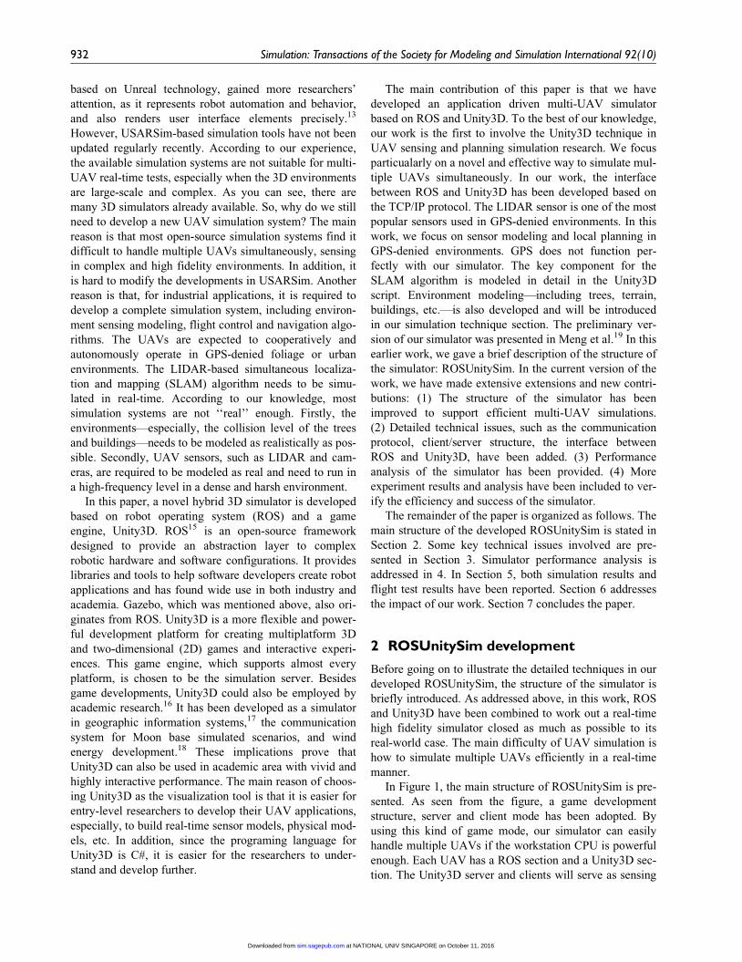
In Figure 1, the main structure of ROSUnitySim is pre-
sented. As seen from the figure, a game development
structure, server and client mode has been adopted. By
using this kind of game mode, our simulator can easily
handle multiple UAVs if the workstation CPU is powerful
enough. Each UAV has a ROS section and a Unity3D sec-
tion. The Unity3D server and clients will serve as sensing
932 Simulation: Transactions of the Society for Modeling and Simulation International 92(10)
at NATIONAL UNIV SINGAPORE on October 11, 2016sim.sagepub.comDownloaded from
environments in real cases. The communication server
section will serve a communication media function, such
as MANET and other commercial products for ad hoc
communication. Figure 2 shows a more detailed system
level structure, which is used by our project. Network and
virtual machine technology are used to support the whole
simulation system. This structure is mainly for the pur-
poses of easy expansion. In one workstation/PC, one or
more UAV can be simulated. And if necessary, more
workstations/PCs can be added easily to provide a more
powerful computation resource. The virtual machines and
Unity3D server/client also can be set up in different work-
stations/PCs, because all the communication systems
between them are based on a network. Hence, the devel-
oped simulator system is scalable. Users can set up their
own structure based on their requirements. In the follow-
ing, we will give brief introductions to each portion of
ROSUnitySim.
2.1 Unity3D section
Unity3D is a game development ecosystem: a powerful
rendering engine fully integrated with a complete set of
Figure 1. Structure of ROSUnitySim. GCS: Ground ControlStation.
Figure 2. System level structure.
Hu and Meng 933
at NATIONAL UNIV SINGAPORE on October 11, 2016sim.sagepub.comDownloaded from
intuitive tools and rapid workflows to create interactive
3D and 2D content, easy multi-platform publishing, thou-
sands of quality, ready-made assets in the Asset Store and
a knowledge-sharing community.20 Unity3D allows game
developers to create games that delight players on any
platform. The high fidelity model, live environment and
ability to adapt to any platform which can be achieved by
Unity3D make it the best choice of our 3D high-fidelity
simulator. Moreover, natural environment and weather
conditions can be simulated in Unity3D too, to monitor
the possible complex outdoor influence on UAV in physi-
cal test through simulations. Though this may still be far
from natural light, we can continue to employ the potential
of Unity3D in environmental simulation. Another crucial
advantage of Unity3D compared to our existing simulator
is that the collision regions of objects can be as narrow
and detailed as the shape of the objects themselves.
2.1.1 3D environment modeling. In order to improve the
confidence level of the simulation system, 3D virtual
environments need to be modeled as realistically as possi-
ble. There are two parts to consider when modeling objects
in the simulator. The first is mesh, which determines the
visual shape of the object: The more meshes used, the
more accurate the depiction of the object. But meshes
require computer resources, so a balance should be consid-
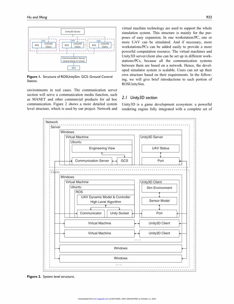
ered based on all requirements. For visualization purposes,
the corresponding textures will be added to the surface of
the mesh. Figure 3(a) shows the tree’s meshes (in blue)
and the rendered results with textures in Unity3D. The
other is a collider, which is used for raycasting, collision
detection and other physic simulations. Just like the mesh,
the detail of the collider should be modeled according to
requirements. Reducing the detail level of the mesh or the
collider may be an alternative choice if Unity3D takes up
too much computer resource.
In the case of the UAV model shown in Figure 3(b),
which we developed for simulation purposes, components
such as the propeller, the body frame and the motor have
been implemented. This model can be easily adapted into
a test of physical control if required.
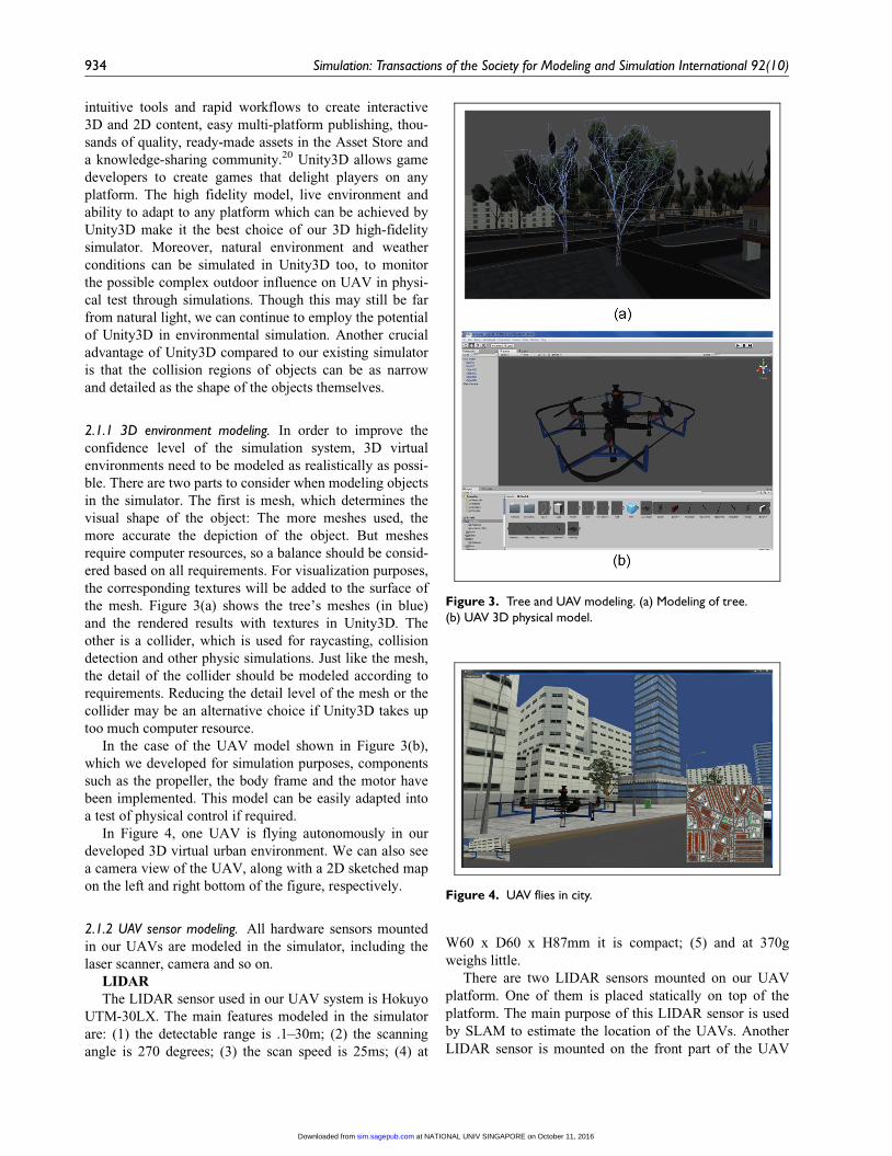
In Figure 4, one UAV is flying autonomously in our
developed 3D virtual urban environment. We can also see
a camera view of the UAV, along with a 2D sketched map
on the left and right bottom of the figure, respectively.
2.1.2 UAV sensor modeling. All hardware sensors mounted
in our UAVs are modeled in the simulator, including the
laser scanner, camera and so on.
LIDAR
The LIDAR sensor used in our UAV system is Hokuyo
UTM-30LX. The main features modeled in the simulator
are: (1) the detectable range is .1–30m; (2) the scanning
angle is 270 degrees; (3) the scan speed is 25ms; (4) at
W60 x D60 x H87mm it is compact; (5) and at 370g
weighs little.
There are two LIDAR sensors mounted on our UAV
platform. One of them is placed statically on top of the
platform. The main purpose of this LIDAR sensor is used
by SLAM to estimate the location of the UAVs. Another
LIDAR sensor is mounted on the front part of the UAV
Figure 3. Tree and UAV modeling. (a) Modeling of tree.(b) UAV 3D physical model.
Figure 4. UAV flies in city.
934 Simulation: Transactions of the Society for Modeling and Simulation International 92(10)
at NATIONAL UNIV SINGAPORE on October 11, 2016sim.sagepub.comDownloaded from
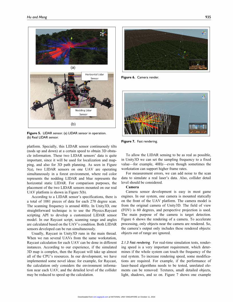
platform. Specially, this LIDAR sensor continuously tilts
(nods up and down) at a certain speed to obtain 3D obsta-
cle information. These two LIDAR sensors’ data is quite
important, since it will be used for localization and map-
ping, and also for 3D path planning. As seen in Figure
5(a), two LIDAR sensors on one UAV are operating
simultaneously in a forest environment, where red color
represents the nodding LIDAR and blue represents the
horizontal static LIDAR. For comparison purposes, the
placement of the two LIDAR sensors mounted on our real
UAV platform is shown in Figure 5(b).
According to a LIDAR sensor’s specifications, there is
a total of 1081 pieces of data for each 270 degree scan.
The scanning frequency is around 40Hz. In Unity3D, one
straightforward technique is to use the Physics.Raycast
scripting API to develop a customized LIDAR sensor
model. In our Raycast script, scanning range and angles
are calculated based on the UAV’s condition. Both LIDAR
sensors developed can be run simultaneously.
Usually, Raycast in Unity3D runs in the main thread.
When we run several UAVs from the same workstation,
Raycast calculation for each UAV can be done in different
instances. According to our experience, if the simulated
3D map is complex, then the Raycast will take up almost
all of the CPU’s resources. In our development, we have
implemented some novel ideas: for example, for Raycast,
the calculation only considers the environment informa-
tion near each UAV, and the detailed level of the collider
may be reduced to speed up the calculation.
To allow the LIDAR sensing to be as real as possible,
in Unity3D we can set the sampling frequency to a fixed
value—for example, 40Hz—even though sometimes the
workstation can support higher frame rates.
For measurement errors, we can add noise to the scan
data to simulate a real laser’s data. Also, collider detail
level should be considered.
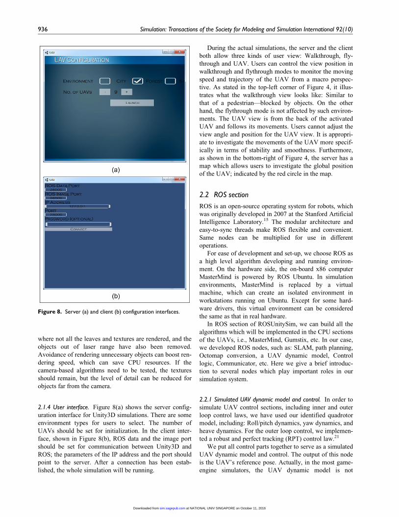
Camera
Camera sensor development is easy in most game
engines. In our system, one camera is mounted statically
on the front of the UAV platform. The camera model is
from the original camera of Unity3D. The field of view
(FOV) is 60 degrees, and perspective projection is used.
The main purpose of the camera is target detection.
Figure 6 shows the rendering of a camera. To accelerate
processing, only objects near the camera are rendered. So,
the camera’s output only includes these rendered objects:
objects out of range are ignored.
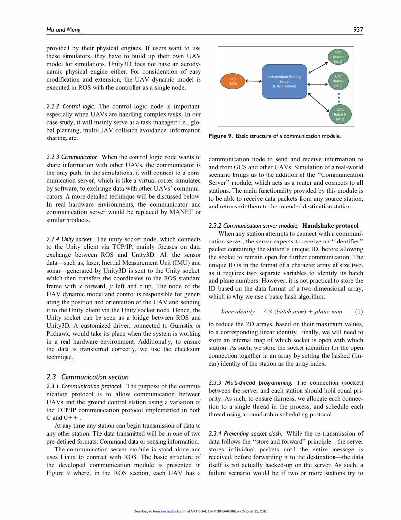
2.1.3 Fast rendering. For real-time simulation tests, render-
ing speed is a very important requirement, which deter-
mines if the whole system can touch the frequency of the
real system. To increase rendering speed, some modifica-
tions are required. For example, if the performance of
laser-based algorithms needs to be tested, unrelated ele-
ments can be removed: Textures, small detailed objects,
light, shadows, and so on. Figure 7 shows one example
Figure 5. LIDAR sensor. (a) LIDAR sensor in operation.(b) Real LIDAR sensor.
Figure 6. Camera render.
Figure 7. Fast rendering.
Hu and Meng 935
at NATIONAL UNIV SINGAPORE on October 11, 2016sim.sagepub.comDownloaded from
where not all the leaves and textures are rendered, and the
objects out of laser range have also been removed.
Avoidance of rendering unnecessary objects can boost ren-
dering speed, which can save CPU resources. If the
camera-based algorithms need to be tested, the textures
should remain, but the level of detail can be reduced for
objects far from the camera.
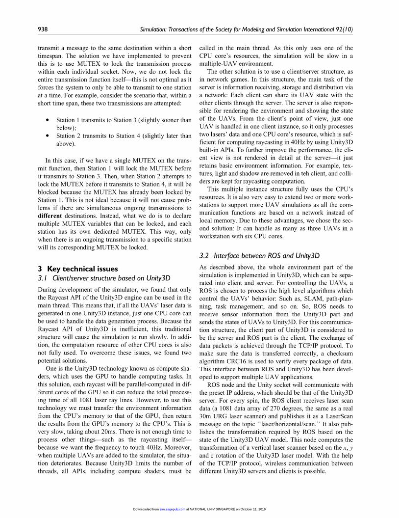
2.1.4 User interface. Figure 8(a) shows the server config-
uration interface for Unity3D simulations. There are some
environment types for users to select. The number of
UAVs should be set for initialization. In the client inter-
face, shown in Figure 8(b), ROS data and the image port
should be set for communication between Unity3D and
ROS; the parameters of the IP address and the port should
point to the server. After a connection has been estab-
lished, the whole simulation will be running.
During the actual simulations, the server and the client
both allow three kinds of user view: Walkthrough, fly-
through and UAV. Users can control the view position in
walkthrough and flythrough modes to monitor the moving
speed and trajectory of the UAV from a macro perspec-
tive. As stated in the top-left corner of Figure 4, it illus-
trates what the walkthrough view looks like: Similar to
that of a pedestrian—blocked by objects. On the other
hand, the flythrough mode is not affected by such environ-
ments. The UAV view is from the back of the activated
UAV and follows its movements. Users cannot adjust the
view angle and position for the UAV view. It is appropri-
ate to investigate the movements of the UAV more specif-
ically in terms of stability and smoothness. Furthermore,
as shown in the bottom-right of Figure 4, the server has a
map which allows users to investigate the global position
of the UAV; indicated by the red circle in the map.
2.2 ROS section
ROS is an open-source operating system for robots, which
was originally developed in 2007 at the Stanford Artificial
Intelligence Laboratory.15 The modular architecture and
easy-to-sync threads make ROS flexible and convenient.
Same nodes can be multiplied for use in different
operations.
For ease of development and set-up, we choose ROS as
a high level algorithm developing and running environ-
ment. On the hardware side, the on-board x86 computer
MasterMind is powered by ROS Ubuntu. In simulation
environments, MasterMind is replaced by a virtual
machine, which can create an isolated environment in
workstations running on Ubuntu. Except for some hard-
ware drivers, this virtual environment can be considered
the same as that in real hardware.
In ROS section of ROSUnitySim, we can build all the
algorithms which will be implemented in the CPU sections
of the UAVs, i.e., MasterMind, Gumstix, etc. In our case,
we developed ROS nodes, such as: SLAM, path planning,
Octomap conversion, a UAV dynamic model, Control
logic, Communicator, etc. Here we give a brief introduc-
tion to several nodes which play important roles in our
simulation system.
2.2.1 Simulated UAV dynamic model and control. In order to
simulate UAV control sections, including inner and outer
loop control laws, we have used our identified quadrotor
model, including: Roll/pitch dynamics, yaw dynamics, and
heave dynamics. For the outer loop control, we implemen-
ted a robust and perfect tracking (RPT) control law.21
We put all control parts together to serve as a simulated
UAV dynamic model and control. The output of this node
is the UAV’s reference pose. Actually, in the most game-
engine simulators, the UAV dynamic model is not
Figure 8. Server (a) and client (b) configuration interfaces.
936 Simulation: Transactions of the Society for Modeling and Simulation International 92(10)
at NATIONAL UNIV SINGAPORE on October 11, 2016sim.sagepub.comDownloaded from
provided by their physical engines. If users want to use
these simulators, they have to build up their own UAV
model for simulations. Unity3D does not have an aerody-
namic physical engine either. For consideration of easy
modification and extension, the UAV dynamic model is
executed in ROS with the controller as a single node.
2.2.2 Control logic. The control logic node is important,
especially when UAVs are handling complex tasks. In our
case study, it will mainly serve as a task manager: i.e., glo-
bal planning, multi-UAV collision avoidance, information
sharing, etc.
2.2.3 Communicator. When the control logic node wants to
share information with other UAVs, the communicator is
the only path. In the simulations, it will connect to a com-
munication server, which is like a virtual router simulated
by software, to exchange data with other UAVs’ communi-
cators. A more detailed technique will be discussed below.
In real hardware environments, the communicator and
communication server would be replaced by MANET or
similar products.
2.2.4 Unity socket. The unity socket node, which connects
to the Unity client via TCP/IP, mainly focuses on data
exchange between ROS and Unity3D. All the sensor
data—such as, laser, Inertial Measurement Unit (IMU) and
sonar—generated by Unity3D is sent to the Unity socket,
which then transfers the coordinates to the ROS standard
frame with x forward, y left and z up. The node of the
UAV dynamic model and control is responsible for gener-
ating the position and orientation of the UAV and sending
it to the Unity client via the Unity socket node. Hence, the
Unity socket can be seen as a bridge between ROS and
Unity3D. A customized driver, connected to Gumstix or
Pixhawk, would take its place when the system is working
in a real hardware environment. Additionally, to ensure
the data is transferred correctly, we use the checksum
technique.
2.3 Communication section2.3.1 Communication protocol. The purpose of the commu-
nication protocol is to allow communication between
UAVs and the ground control station using a variation of
the TCP/IP communication protocol implemented in both
C and C++ .
At any time any station can begin transmission of data to
any other station. The data transmitted will be in one of two
pre-defined formats: Command data or sensing information.
The communication server module is stand-alone and
uses Linux to connect with ROS. The basic structure of
the developed communication module is presented in
Figure 9 where, in the ROS section, each UAV has a
communication node to send and receive information to
and from GCS and other UAVs. Simulation of a real-world
scenario brings us to the addition of the ‘‘Communication
Server’’ module, which acts as a router and connects to all
stations. The main functionality provided by this module is
to be able to receive data packets from any source station,
and retransmit them to the intended destination station.
2.3.2 Communication server module. Handshake protocol
When any station attempts to connect with a communi-
cation server, the server expects to receive an ‘‘identifier’’
packet containing the station’s unique ID, before allowing
the socket to remain open for further communication. The
unique ID is in the format of a character array of size two,
as it requires two separate variables to identify its batch
and plane numbers. However, it is not practical to store the
ID based on the data format of a two-dimensional array,
which is why we use a basic hash algorithm:
liner identity= 43 (batch num)+ plane num ð1Þ
to reduce the 2D arrays, based on their maximum values,
to a corresponding linear identity. Finally, we will need to
store an internal map of which socket is open with which
station. As such, we store the socket identifier for the open
connection together in an array by setting the hashed (lin-
ear) identity of the station as the array index.
2.3.3 Multi-thread programming. The connection (socket)
between the server and each station should hold equal pri-
ority. As such, to ensure fairness, we allocate each connec-
tion to a single thread in the process, and schedule each
thread using a round-robin scheduling protocol.
2.3.4 Preventing socket clash. While the re-transmission of
data follows the ‘‘store and forward’’ principle—the server
stores individual packets until the entire message is
received, before forwarding it to the destination—the data
itself is not actually backed-up on the server. As such, a
failure scenario would be if two or more stations try to
Figure 9. Basic structure of a communication module.
Hu and Meng 937
at NATIONAL UNIV SINGAPORE on October 11, 2016sim.sagepub.comDownloaded from
transmit a message to the same destination within a short
timespan. The solution we have implemented to prevent
this is to use MUTEX to lock the transmission process
within each individual socket. Now, we do not lock the
entire transmission function itself—this is not optimal as it
forces the system to only be able to transmit to one station
at a time. For example, consider the scenario that, within a
short time span, these two transmissions are attempted:
� Station 1 transmits to Station 3 (slightly sooner than
below);� Station 2 transmits to Station 4 (slightly later than
above).
In this case, if we have a single MUTEX on the trans-
mit function, then Station 1 will lock the MUTEX before
it transmits to Station 3. Then, when Station 2 attempts to
lock the MUTEX before it transmits to Station 4, it will be
blocked because the MUTEX has already been locked by
Station 1. This is not ideal because it will not cause prob-
lems if there are simultaneous ongoing transmissions to
different destinations. Instead, what we do is to declare
multiple MUTEX variables that can be locked, and each
station has its own dedicated MUTEX. This way, only
when there is an ongoing transmission to a specific station
will its corresponding MUTEX be locked.
3 Key technical issues3.1 Client/server structure based on Unity3D
During development of the simulator, we found that only
the Raycast API of the Unity3D engine can be used in the
main thread. This means that, if all the UAVs’ laser data is
generated in one Unity3D instance, just one CPU core can
be used to handle the data generation process. Because the
Raycast API of Unity3D is inefficient, this traditional
structure will cause the simulation to run slowly. In addi-
tion, the computation resource of other CPU cores is also
not fully used. To overcome these issues, we found two
potential solutions.
One is the Unity3D technology known as compute sha-
ders, which uses the GPU to handle computing tasks. In
this solution, each raycast will be parallel-computed in dif-
ferent cores of the GPU so it can reduce the total process-
ing time of all 1081 laser ray lines. However, to use this
technology we must transfer the environment information
from the CPU’s memory to that of the GPU, then return
the results from the GPU’s memory to the CPU’s. This is
very slow, taking about 20ms. There is not enough time to
process other things—such as the raycasting itself—
because we want the frequency to touch 40Hz. Moreover,
when multiple UAVs are added to the simulator, the situa-
tion deteriorates. Because Unity3D limits the number of
threads, all APIs, including compute shaders, must be
called in the main thread. As this only uses one of the
CPU core’s resources, the simulation will be slow in a
multiple-UAV environment.
The other solution is to use a client/server structure, as
in network games. In this structure, the main task of the
server is information receiving, storage and distribution via
a network: Each client can share its UAV state with the
other clients through the server. The server is also respon-
sible for rendering the environment and showing the state
of the UAVs. From the client’s point of view, just one
UAV is handled in one client instance, so it only processes
two lasers’ data and one CPU core’s resource, which is suf-
ficient for computing raycasting in 40Hz by using Unity3D
built-in APIs. To further improve the performance, the cli-
ent view is not rendered in detail at the server—it just
retains basic environment information. For example, tex-
tures, light and shadow are removed in teh client, and colli-
ders are kept for raycasting computation.
This multiple instance structure fully uses the CPU’s
resources. It is also very easy to extend two or more work-
stations to support more UAV simulations as all the com-
munication functions are based on a network instead of
local memory. Due to these advantages, we chose the sec-
ond solution: It can handle as many as three UAVs in a
workstation with six CPU cores.
3.2 Interface between ROS and Unity3D
As described above, the whole environment part of the
simulation is implemented in Unity3D, which can be sepa-
rated into client and server. For controlling the UAVs, a
ROS is chosen to process the high level algorithms which
control the UAVs’ behavior: Such as, SLAM, path-plan-
ning, task management, and so on. So, ROS needs to
receive sensor information from the Unity3D part and
sends the states of UAVs to Unity3D. For this communica-
tion structure, the client part of Unity3D is considered to
be the server and ROS part is the client. The exchange of
data packets is achieved through the TCP/IP protocol. To
make sure the data is transferred correctly, a checksum
algorithm CRC16 is used to verify every package of data.
This interface between ROS and Unity3D has been devel-
oped to support multiple UAV applications.
ROS node and the Unity socket will communicate with
the preset IP address, which should be that of the Unity3D
server. For every spin, the ROS client receives laser scan
data (a 1081 data array of 270 degrees, the same as a real
30m URG laser scanner) and publishes it as a LaserScan
message on the topic ‘‘laser/horizontal/scan.’’ It also pub-
lishes the transformation required by ROS based on the
state of the Unity3D UAV model. This node computes the
transformation of a vertical laser scanner based on the x, y
and z rotation of the Unity3D laser model. With the help
of the TCP/IP protocol, wireless communication between
different Unity3D servers and clients is possible.
938 Simulation: Transactions of the Society for Modeling and Simulation International 92(10)
at NATIONAL UNIV SINGAPORE on October 11, 2016sim.sagepub.comDownloaded from
Originally, we implemented a local interface which
allowed Unity3D and C++ control logic to access the
same memory for data exchange. However, this interface
can only be used on a Windows platform, which means it
can’t communicate with ROS, which usually runs in
Ubuntu. Using a network protocol instead not only solves
this issue, but also realizes communication between a
remote server and its client. Currently, we have managed
to develop a ROS/Unity3D interface, which can support
multiple UAV data transmissions.
Additionally, for images captured from the simulator’s
camera transmissions, another channel is created, which
means the camera data processing is standalone. The Unity
client listens to a special port, and when an image receiver
connects to it from ROS, it will send images at a particular
frequency. We know that image transmission and process-
ing is a high load task, so this design separates the image
task from other tasks.
3.3 Distributed computation
Thanks to the network-based client/server structure, the
whole simulation task can be separated into several sub-
tasks, whic can be assigned to any PC or workstation, as
long as they are in the same network. For Unity3D, the ser-
ver and each client are designed as standalone items, so
they can be set up either on several common PCs or on a
powerful workstation. And in ROS each node can also be
put in a different computer, which is more flexible—useful
when simulating multiple UAVs. From the results of our
experiment, a six-core workstation can only handle three
UAVs. If we want to process more UAVs at the same time,
more PCs or workstations can be added easily without any
software modification. Furthermore, in most situations,
three common dual-core PCs have more powerful parallel
computation ability than a six-core workstation, and their
total price is less than a workstation’s. So, for considera-
tions of economy, distributed computation support pro-
vides more choice when simulating multiple UAVs.
4 Performance analysis4.1 CPU Usage
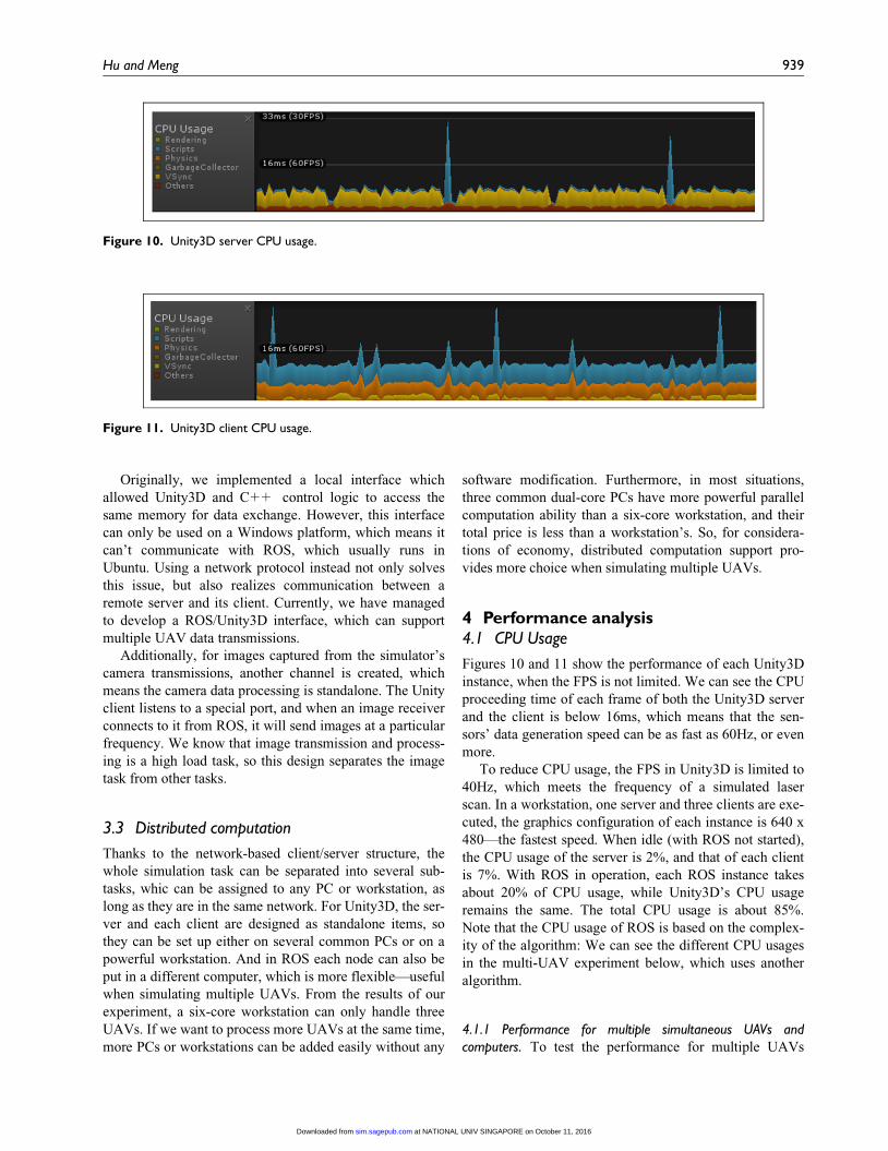
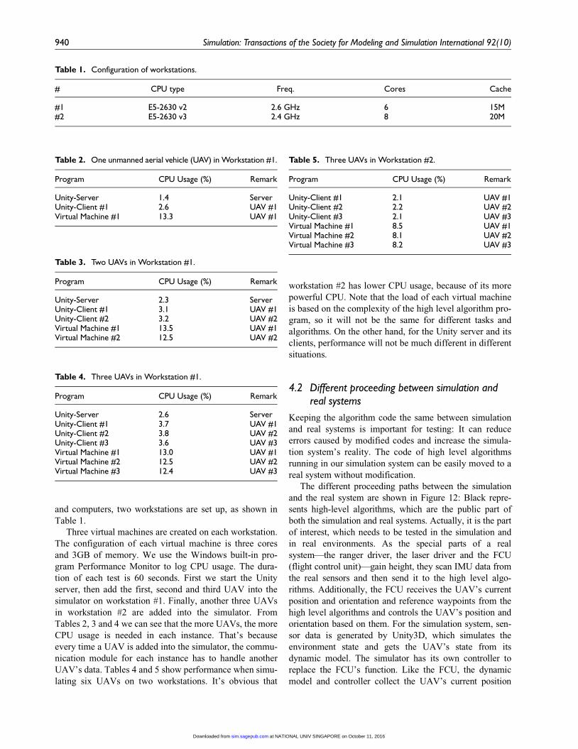
Figures 10 and 11 show the performance of each Unity3D
instance, when the FPS is not limited. We can see the CPU
proceeding time of each frame of both the Unity3D server
and the client is below 16ms, which means that the sen-
sors’ data generation speed can be as fast as 60Hz, or even
more.
To reduce CPU usage, the FPS in Unity3D is limited to
40Hz, which meets the frequency of a simulated laser
scan. In a workstation, one server and three clients are exe-
cuted, the graphics configuration of each instance is 640 x
480—the fastest speed. When idle (with ROS not started),
the CPU usage of the server is 2%, and that of each client
is 7%. With ROS in operation, each ROS instance takes
about 20% of CPU usage, while Unity3D’s CPU usage
remains the same. The total CPU usage is about 85%.
Note that the CPU usage of ROS is based on the complex-
ity of the algorithm: We can see the different CPU usages
in the multi-UAV experiment below, which uses another
algorithm.
4.1.1 Performance for multiple simultaneous UAVs andcomputers. To test the performance for multiple UAVs
Figure 10. Unity3D server CPU usage.
Figure 11. Unity3D client CPU usage.
Hu and Meng 939
at NATIONAL UNIV SINGAPORE on October 11, 2016sim.sagepub.comDownloaded from
and computers, two workstations are set up, as shown in
Table 1.
Three virtual machines are created on each workstation.
The configuration of each virtual machine is three cores
and 3GB of memory. We use the Windows built-in pro-
gram Performance Monitor to log CPU usage. The dura-
tion of each test is 60 seconds. First we start the Unity
server, then add the first, second and third UAV into the
simulator on workstation #1. Finally, another three UAVs
in workstation #2 are added into the simulator. From
Tables 2, 3 and 4 we can see that the more UAVs, the more
CPU usage is needed in each instance. That’s because
every time a UAV is added into the simulator, the commu-
nication module for each instance has to handle another
UAV’s data. Tables 4 and 5 show performance when simu-
lating six UAVs on two workstations. It’s obvious that
workstation #2 has lower CPU usage, because of its more
powerful CPU. Note that the load of each virtual machine
is based on the complexity of the high level algorithm pro-
gram, so it will not be the same for different tasks and
algorithms. On the other hand, for the Unity server and its
clients, performance will not be much different in different
situations.
4.2 Different proceeding between simulation andreal systems
Keeping the algorithm code the same between simulation
and real systems is important for testing: It can reduce
errors caused by modified codes and increase the simula-
tion system’s reality. The code of high level algorithms
running in our simulation system can be easily moved to a
real system without modification.
The different proceeding paths between the simulation
and the real system are shown in Figure 12: Black repre-
sents high-level algorithms, which are the public part of
both the simulation and real systems. Actually, it is the part
of interest, which needs to be tested in the simulation and
in real environments. As the special parts of a real
system—the ranger driver, the laser driver and the FCU
(flight control unit)—gain height, they scan IMU data from
the real sensors and then send it to the high level algo-
rithms. Additionally, the FCU receives the UAV’s current
position and orientation and reference waypoints from the
high level algorithms and controls the UAV’s position and
orientation based on them. For the simulation system, sen-
sor data is generated by Unity3D, which simulates the
environment state and gets the UAV’s state from its
dynamic model. The simulator has its own controller to
replace the FCU’s function. Like the FCU, the dynamic
model and controller collect the UAV’s current position
Table 1. Configuration of workstations.
# CPU type Freq. Cores Cache
#1 E5-2630 v2 2.6 GHz 6 15M#2 E5-2630 v3 2.4 GHz 8 20M
Table 2. One unmanned aerial vehicle (UAV) in Workstation #1.
Program CPU Usage (%) Remark
Unity-Server 1.4 ServerUnity-Client #1 2.6 UAV #1Virtual Machine #1 13.3 UAV #1
Table 3. Two UAVs in Workstation #1.
Program CPU Usage (%) Remark
Unity-Server 2.3 ServerUnity-Client #1 3.1 UAV #1Unity-Client #2 3.2 UAV #2Virtual Machine #1 13.5 UAV #1Virtual Machine #2 12.5 UAV #2
Table 4. Three UAVs in Workstation #1.
Program CPU Usage (%) Remark
Unity-Server 2.6 ServerUnity-Client #1 3.7 UAV #1Unity-Client #2 3.8 UAV #2Unity-Client #3 3.6 UAV #3Virtual Machine #1 13.0 UAV #1Virtual Machine #2 12.5 UAV #2Virtual Machine #3 12.4 UAV #3
Table 5. Three UAVs in Workstation #2.
Program CPU Usage (%) Remark
Unity-Client #1 2.1 UAV #1Unity-Client #2 2.2 UAV #2Unity-Client #3 2.1 UAV #3Virtual Machine #1 8.5 UAV #1Virtual Machine #2 8.1 UAV #2Virtual Machine #3 8.2 UAV #3
940 Simulation: Transactions of the Society for Modeling and Simulation International 92(10)
at NATIONAL UNIV SINGAPORE on October 11, 2016sim.sagepub.comDownloaded from
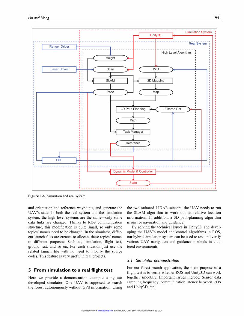
and orientation and reference waypoints, and generate the
UAV’s state. In both the real system and the simulation
system, the high level systems are the same—only some
data links are changed. Thanks to ROS communication
structure, this modification is quite small, so only some
topics’ names need to be changed. In the simulator, differ-
ent launch files are created to allocate these topics’ names
to different purposes: Such as, simulation, flight test,
ground test, and so on. For each situation just use the
related launch file with no need to modify the source
codes. This feature is very useful in real projects.
5 From simulation to a real flight test
Here we provide a demonstration example using our
developed simulator. One UAV is supposed to search
the forest autonomously without GPS information. Using
the two onboard LIDAR sensors, the UAV needs to run
the SLAM algorithm to work out its relative location
information. In addition, a 3D path-planning algorithm
is run for navigation and guidance.
By solving the technical issues in Unity3D and devel-
oping the UAV’s model and control algorithms in ROS,
our hybrid simulation system can be used to test and verify
various UAV navigation and guidance methods in clut-
tered environments.
5.1 Simulator demonstration
For our forest search application, the main purpose of a
flight test is to verify whether ROS and Unity3D can work
together smoothly. Important issues include: Sensor data
sampling frequency, communication latency between ROS
and Unity3D, etc.
Figure 12. Simulation and real system.
Hu and Meng 941
at NATIONAL UNIV SINGAPORE on October 11, 2016sim.sagepub.comDownloaded from
The workstation we used for our simulation system is a
six-core, E5-2630v2 processor. The graphic card of this
PC is GTX 780 Ti. Currently, according to our test, this
workstation can handle three UAVs simultaneously run-
ning 40Hz LIDAR sensing in a complex 500m 3 500m
forest map developed in Unity3D.
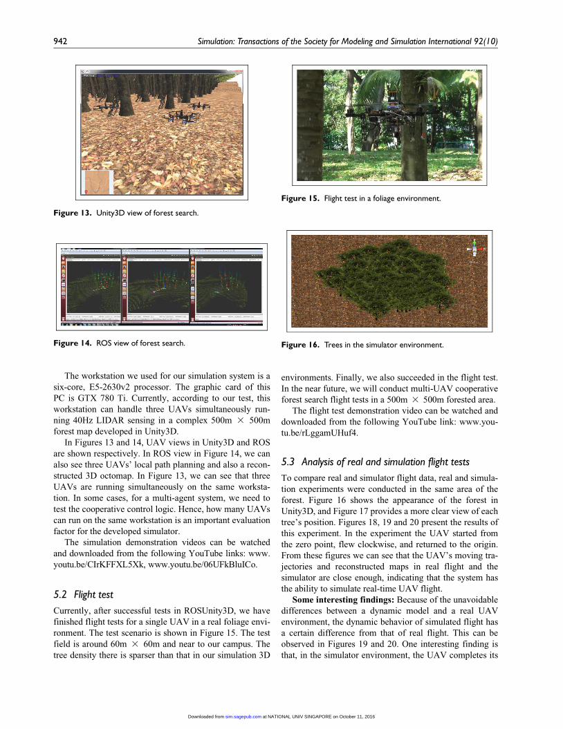
In Figures 13 and 14, UAV views in Unity3D and ROS
are shown respectively. In ROS view in Figure 14, we can
also see three UAVs’ local path planning and also a recon-
structed 3D octomap. In Figure 13, we can see that three
UAVs are running simultaneously on the same worksta-
tion. In some cases, for a multi-agent system, we need to
test the cooperative control logic. Hence, how many UAVs
can run on the same workstation is an important evaluation
factor for the developed simulator.
The simulation demonstration videos can be watched
and downloaded from the following YouTube links: www.
youtu.be/CIrKFFXL5Xk, www.youtu.be/06UFkBluICo.
5.2 Flight test
Currently, after successful tests in ROSUnity3D, we have
finished flight tests for a single UAV in a real foliage envi-
ronment. The test scenario is shown in Figure 15. The test
field is around 60m 3 60m and near to our campus. The
tree density there is sparser than that in our simulation 3D
environments. Finally, we also succeeded in the flight test.
In the near future, we will conduct multi-UAV cooperative
forest search flight tests in a 500m 3 500m forested area.
The flight test demonstration video can be watched and
downloaded from the following YouTube link: www.you-
tu.be/rLggamUHuf4.
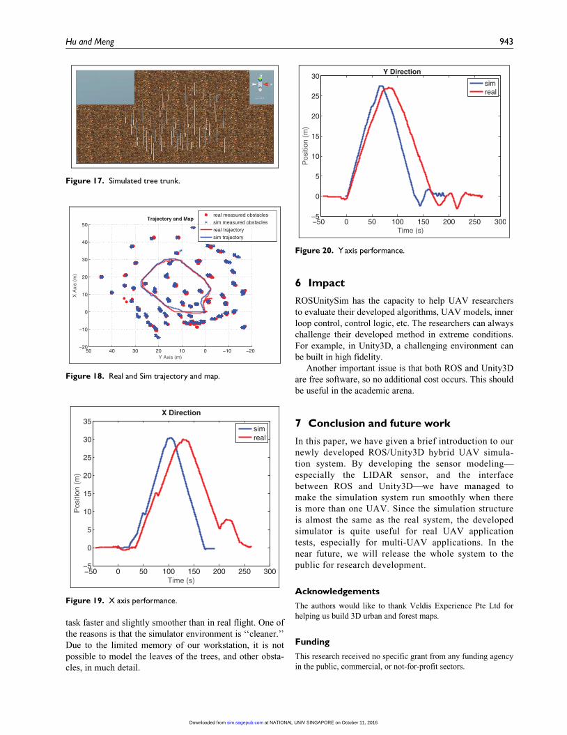
5.3 Analysis of real and simulation flight tests
To compare real and simulator flight data, real and simula-
tion experiments were conducted in the same area of the
forest. Figure 16 shows the appearance of the forest in
Unity3D, and Figure 17 provides a more clear view of each
tree’s position. Figures 18, 19 and 20 present the results of
this experiment. In the experiment the UAV started from
the zero point, flew clockwise, and returned to the origin.
From these figures we can see that the UAV’s moving tra-
jectories and reconstructed maps in real flight and the
simulator are close enough, indicating that the system has
the ability to simulate real-time UAV flight.
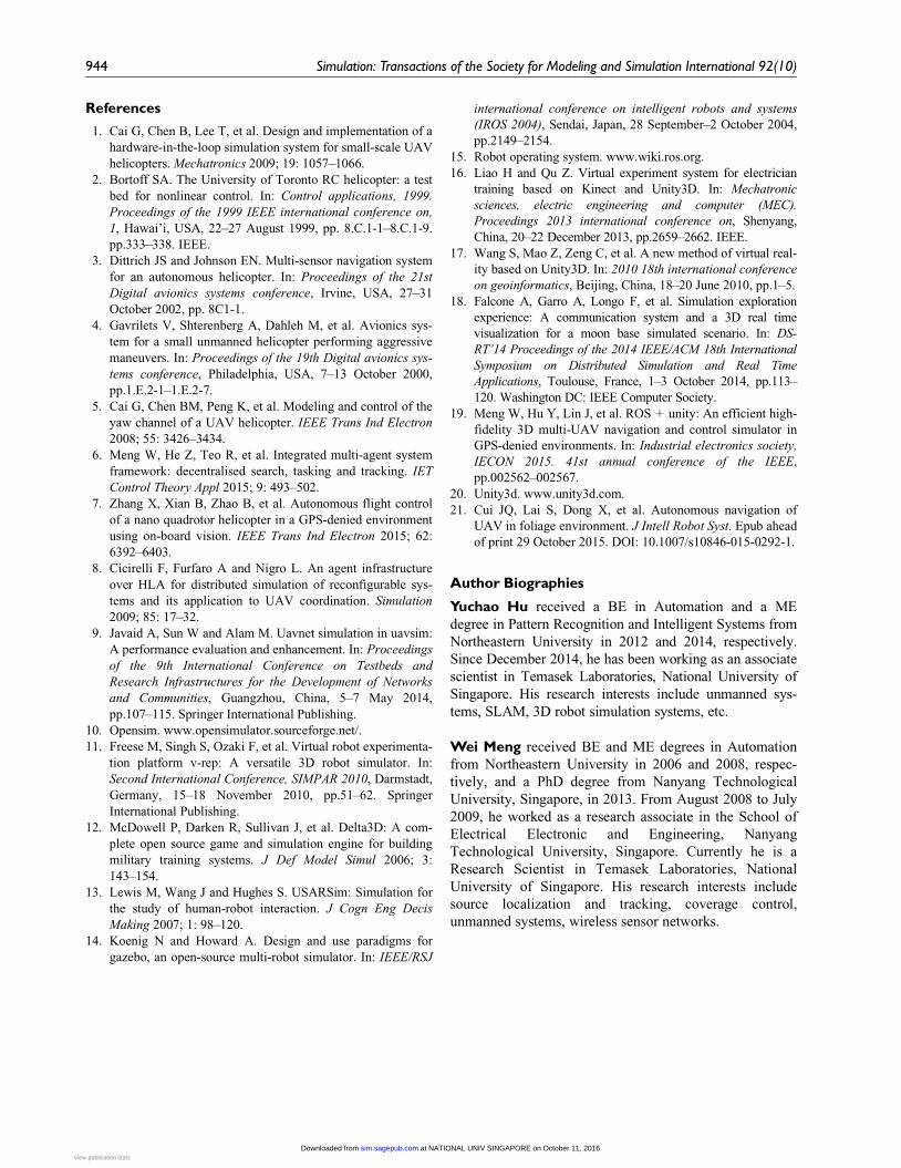
Some interesting findings: Because of the unavoidable
differences between a dynamic model and a real UAV
environment, the dynamic behavior of simulated flight has
a certain difference from that of real flight. This can be
observed in Figures 19 and 20. One interesting finding is
that, in the simulator environment, the UAV completes its
Figure 13. Unity3D view of forest search.
Figure 14. ROS view of forest search.
Figure 15. Flight test in a foliage environment.
Figure 16. Trees in the simulator environment.
942 Simulation: Transactions of the Society for Modeling and Simulation International 92(10)
at NATIONAL UNIV SINGAPORE on October 11, 2016sim.sagepub.comDownloaded from
task faster and slightly smoother than in real flight. One of
the reasons is that the simulator environment is ‘‘cleaner.’’
Due to the limited memory of our workstation, it is not
possible to model the leaves of the trees, and other obsta-
cles, in much detail.
6 Impact
ROSUnitySim has the capacity to help UAV researchers
to evaluate their developed algorithms, UAV models, inner
loop control, control logic, etc. The researchers can always
challenge their developed method in extreme conditions.
For example, in Unity3D, a challenging environment can
be built in high fidelity.
Another important issue is that both ROS and Unity3D
are free software, so no additional cost occurs. This should
be useful in the academic arena.
7 Conclusion and future work
In this paper, we have given a brief introduction to our
newly developed ROS/Unity3D hybrid UAV simula-
tion system. By developing the sensor modeling—
especially the LIDAR sensor, and the interface
between ROS and Unity3D—we have managed to
make the simulation system run smoothly when there
is more than one UAV. Since the simulation structure
is almost the same as the real system, the developed
simulator is quite useful for real UAV application
tests, especially for multi-UAV applications. In the
near future, we will release the whole system to the
public for research development.
Acknowledgements
The authors would like to thank Veldis Experience Pte Ltd for
helping us build 3D urban and forest maps.
Funding
This research received no specific grant from any funding agency
in the public, commercial, or not-for-profit sectors.
Figure 17. Simulated tree trunk.
Figure 18. Real and Sim trajectory and map.
Figure 19. X axis performance.
Figure 20. Yaxis performance.
Hu and Meng 943
at NATIONAL UNIV SINGAPORE on October 11, 2016sim.sagepub.comDownloaded from
References
1. Cai G, Chen B, Lee T, et al. Design and implementation of a
hardware-in-the-loop simulation system for small-scale UAV
helicopters. Mechatronics 2009; 19: 1057–1066.
2. Bortoff SA. The University of Toronto RC helicopter: a test
bed for nonlinear control. In: Control applications, 1999.
Proceedings of the 1999 IEEE international conference on,
1, Hawai’i, USA, 22–27 August 1999, pp. 8.C.1-1–8.C.1-9.
pp.333–338. IEEE.
3. Dittrich JS and Johnson EN. Multi-sensor navigation system
for an autonomous helicopter. In: Proceedings of the 21st
Digital avionics systems conference, Irvine, USA, 27–31
October 2002, pp. 8C1-1.
4. Gavrilets V, Shterenberg A, Dahleh M, et al. Avionics sys-
tem for a small unmanned helicopter performing aggressive
maneuvers. In: Proceedings of the 19th Digital avionics sys-
tems conference, Philadelphia, USA, 7–13 October 2000,
pp.1.E.2-1–1.E.2-7.
5. Cai G, Chen BM, Peng K, et al. Modeling and control of the
yaw channel of a UAV helicopter. IEEE Trans Ind Electron
2008; 55: 3426–3434.
6. Meng W, He Z, Teo R, et al. Integrated multi-agent system
framework: decentralised search, tasking and tracking. IET
Control Theory Appl 2015; 9: 493–502.
7. Zhang X, Xian B, Zhao B, et al. Autonomous flight control
of a nano quadrotor helicopter in a GPS-denied environment
using on-board vision. IEEE Trans Ind Electron 2015; 62:
6392–6403.
8. Cicirelli F, Furfaro A and Nigro L. An agent infrastructure
over HLA for distributed simulation of reconfigurable sys-
tems and its application to UAV coordination. Simulation
2009; 85: 17–32.
9. Javaid A, Sun W and Alam M. Uavnet simulation in uavsim:
A performance evaluation and enhancement. In: Proceedings
of the 9th International Conference on Testbeds and
Research Infrastructures for the Development of Networks
and Communities, Guangzhou, China, 5–7 May 2014,
pp.107–115. Springer International Publishing.
10. Opensim. www.opensimulator.sourceforge.net/.
11. Freese M, Singh S, Ozaki F, et al. Virtual robot experimenta-
tion platform v-rep: A versatile 3D robot simulator. In:
Second International Conference, SIMPAR 2010, Darmstadt,
Germany, 15–18 November 2010, pp.51–62. Springer
International Publishing.
12. McDowell P, Darken R, Sullivan J, et al. Delta3D: A com-
plete open source game and simulation engine for building
military training systems. J Def Model Simul 2006; 3:
143–154.
13. Lewis M, Wang J and Hughes S. USARSim: Simulation for
the study of human-robot interaction. J Cogn Eng Decis
Making 2007; 1: 98–120.
14. Koenig N and Howard A. Design and use paradigms for
gazebo, an open-source multi-robot simulator. In: IEEE/RSJ
international conference on intelligent robots and systems
(IROS 2004), Sendai, Japan, 28 September–2 October 2004,
pp.2149–2154.
15. Robot operating system. www.wiki.ros.org.
16. Liao H and Qu Z. Virtual experiment system for electrician
training based on Kinect and Unity3D. In: Mechatronic
sciences, electric engineering and computer (MEC).
Proceedings 2013 international conference on, Shenyang,
China, 20–22 December 2013, pp.2659–2662. IEEE.
17. Wang S, Mao Z, Zeng C, et al. A new method of virtual real-
ity based on Unity3D. In: 2010 18th international conference
on geoinformatics, Beijing, China, 18–20 June 2010, pp.1–5.
18. Falcone A, Garro A, Longo F, et al. Simulation exploration
experience: A communication system and a 3D real time
visualization for a moon base simulated scenario. In: DS-
RT’14 Proceedings of the 2014 IEEE/ACM 18th International
Symposium on Distributed Simulation and Real Time
Applications, Toulouse, France, 1–3 October 2014, pp.113–
120. Washington DC: IEEE Computer Society.
19. Meng W, Hu Y, Lin J, et al. ROS+ unity: An efficient high-
fidelity 3D multi-UAV navigation and control simulator in
GPS-denied environments. In: Industrial electronics society,
IECON 2015. 41st annual conference of the IEEE,
pp.002562–002567.
20. Unity3d. www.unity3d.com.
21. Cui JQ, Lai S, Dong X, et al. Autonomous navigation of
UAV in foliage environment. J Intell Robot Syst. Epub ahead
of print 29 October 2015. DOI: 10.1007/s10846-015-0292-1.
Author Biographies
Yuchao Hu received a BE in Automation and a ME
degree in Pattern Recognition and Intelligent Systems from
Northeastern University in 2012 and 2014, respectively.
Since December 2014, he has been working as an associate
scientist in Temasek Laboratories, National University of
Singapore. His research interests include unmanned sys-
tems, SLAM, 3D robot simulation systems, etc.
Wei Meng received BE and ME degrees in Automation
from Northeastern University in 2006 and 2008, respec-
tively, and a PhD degree from Nanyang Technological
University, Singapore, in 2013. From August 2008 to July
2009, he worked as a research associate in the School of
Electrical Electronic and Engineering, Nanyang
Technological University, Singapore. Currently he is a
Research Scientist in Temasek Laboratories, National
University of Singapore. His research interests include
source localization and tracking, coverage control,
unmanned systems, wireless sensor networks.
944 Simulation: Transactions of the Society for Modeling and Simulation International 92(10)
at NATIONAL UNIV SINGAPORE on October 11, 2016sim.sagepub.comDownloaded from View publication statsView publication stats