Embed Size (px)
Citation preview
7/25/2019 Rotary Care & Maintenance Handbook
http://slidepdf.com/reader/full/rotary-care-maintenance-handbook 1/116
www.nov.com
Rotary Care & Maintenance
Handbook
U S E R ’ S
M A N U A
L
REFERENCE
Rotary Care & Maintenance Handbook
VarcoBJ BV
Nijverheidsweg 454879 AP Etten-Leur
P.O. Box 174870 AA Etten-Leur The NetherlandsTel + 31-76-5083000
Fax + 31-76-5046000
www.nov.com
DOCUMENT NUMBER
50000840-MAN-001REV
C
REFERENCE DESCRIPTION
User’s Manuals
This document contains proprietary and confidential
information which is the property of National Oilwell
Varco, L.p, its affiliates or subsidiaries (all collectively referred
to hereinafter as "NOV"). It is loaned for limited purposes
only and remains the property of NOV. Reproduction, inwhole or in part, or use of this design or distribution of this
information to others is not permitted without the express
written consent of NOV. This document is to be returned to
NOV upon request or upon completion of the use for which
it was loaned. This document and the information contained
and represented herein is the copyrighted property of NOV.
Nov 2011
Original Instructions

7/25/2019 Rotary Care & Maintenance Handbook
http://slidepdf.com/reader/full/rotary-care-maintenance-handbook 2/116

7/25/2019 Rotary Care & Maintenance Handbook
http://slidepdf.com/reader/full/rotary-care-maintenance-handbook 3/116
GENER L INFORM TION
WWW NOV COM
N TION L OILWELL V RCO

7/25/2019 Rotary Care & Maintenance Handbook
http://slidepdf.com/reader/full/rotary-care-maintenance-handbook 4/116
N TION L OILWELL V RCO
WWW NOV COM

7/25/2019 Rotary Care & Maintenance Handbook
http://slidepdf.com/reader/full/rotary-care-maintenance-handbook 5/116
GENERAL INFORMATION
ABOUT THIS ISSUE
This book is the new
version
of the National Oilwell Varco® (NOV)
rotary
care and
maintenance handbook which has
been used
over
many years. Technology
and products
have been improved
over
the
years, however, the principles of maintaining the equipment has
not.
This issue contains information about new
products like lifting
gear,
adapter
rings
and master bushings.
Some
information about
products
which have been discontinued has been removed, like
MOP
MDS,
KRVS,
KRBM,
KRP KRS roller kelly
bushings.
This
book can be
read in conjunction
with the Rotary and Handling
Tools Catalog (0391 000838-MKT-001).
It
also
can
be
considered
to
be the User s Manuals according to the Machinery Directive
2006 421
EC,
containing
all
information for safe use, maintennance
and
repair.
Nevertheless
it must be said
that
in
case
an
User s
Manual excist, the
User s Manual prevails.
THE CARE AND MAINTENANCE OF ROTARY
EQUIPMENT
The search
for energy continues
at an
ever-increasing
rate.
Wells
are
being
drilled daily to
greater
depths
than
were
thought
possible
only
ageneration ago. These
deep
wells place great demands on
both
the
rig s rotary
equipment and
the
crews
that operate and
maintain it.
The
rotary
equipment
is
the very heart of the
drilling
operation.
Allot of drilling operations center around the conventional master
bushing,
slips, kelly
and
kelly bushing.
Even
though this equipment
is
designed for long service life
and
is
able
to absorb a
certain amount
of
mistreatment, it will eventually wear out.
When
apiece
of
rotary
equipment fails in
use, the results
are often
dangerous and always expensive.
Aplanned program of regular inspection and maintenance will save
a
great
deal of
rig time and money. The
real problem
seems
to
be
that
rotary
equipment
on
the rig may remain
in
service
for several
years
without failure, and
its
performance
is
taken for granted. All too
often, the
only time a
problem appears is when
a
kelly turns through
a kelly
bushing,
or when pipe is inspected, and several
jOints must be
discarded due to bottlenecking
in
the slip area.
The purpose of
this handbook is to
avoid expensive damage
to drill
pipe, drill collars, and kellys due to improper handling and equipment
maintenance.
Although
NOV
equipment is
shown extensively
throughout this
handbook;
inspection, maintenance, and operating principles
are
essentially the same
for
all manufacturers products.
PATENT INFO
Products in
this catalog are covered by
(but
not limited to)
the
following
patents:
US6,845,814 B2; US6,845,814 B2; US6,845,814
B2; US6,845,814
B2; US6,845,814 B2;
W003060280;
US6,896,048; US 6,896,048;
US
6,896,048;US 6,896,048; US4,446,761; US4,446,761;
W02005059299; GB2004/003413; USP
101734 923; USSN
10/807 642; USSN
60/567 236;
W00052297; EP1475512;
US2006005962; US2002074132; US6,443,241; US6,527,493;
US6,691 ,801; US6,637,526; US6,938,709; WO.03/025444;
WO.03/054338; US6,845,814 B2;
W00052297;
EP1475512;
US2006005962; US2002074132; US6,443,241; US6,527,493;
US6,691
,801;
US6,637,526; US6,938,709; WO.03/025444;
WO.03/054338;
US6,845,814 B2;
W02005045177;
US 2005/0077084;
W02005106185;
PCT/GB2004/0050001;
US No. 601567 235;
US6,845,814
B2; CA1087162;
US4,203,182;
CA1087162;
US4,203,182; US4,446,761; WO 2005/059299; US7,510,006,
US.
7,591,304
WWW NOV COM
COPYRIGHT INFO
©
Copyright NOV 2010 Varco
LP.
All rights reserved.
NOV and
Varco are
registered
trademarks
of
NOV
Varco IIP®
reg.
U.S.
Patent Trademark Office.
This
publication
is
the property
of,
and
contains information proprietary to NOV,
Varco IIP®.
No part of
this
publication may
be reproduced or copied
in
any
form, or by any means,
including electronic, mechanical, photocopying, recording or otherwise,
without the prior written
permission
of NOV, Varco
LP.
All product,
brand, or
trade names
used in this publication are the
trademarks or registered trademarks of their respective owners.
Information in this book is subject to change without notice.
LIABILITY
This book is
intended to provide general information. Every effort
has been made to ensure the accuracy of
the
information contained
herein. NOV will
not
be held liable for errors
in
this
material,
or
for
consequences arising from
misuse
of
this material.
LIMITED WARRANTY
The warranty will
be
void
if the tools
or parts were either:
unauthorized
modified
replacement
parts not
manufactured
by
NOV
were
utilized
not properly stored
or
maintainedAIl PIB s
are
available
from www
nov.
com - solutions - drilling
Special information
Detailed
descriptions
of standard workshop procedures, safety
principles
and
service operations are not included. Please note that
this book may contain warnings about procedures which could
damage
equipment,
make it unsafe, or cause PERSONAL INJURY.
Please
understand that these warnings cannot cover
all
conceivable ways
in which
service (whether or not recommended by NOV) might be
done, or the
possible hazardous consequences
of each conceivable
ways. Anyone using service procedures or tools, whether or not
recommended by NOV, must
be
thoroughly
satisfied
that neither
personal safety
nor
equipment safety
will
be
jeopardized.
All
information contained in this book
is based
upon the latest product
information available at any time of
printing.
We
reserve
the right to
make changes at any time
without
notice.
INTENDED AUDIENCE
This
book
is intended for use by field engineering, installation,
operation, and repair personnel. Every effort has been made to
ensure
the accuracy
of the information contained herein. NOV, Varco®
2010,
NOV
LP will not
be held
liable for errors in
this
material,
or
for
consequences arising from misuse of this
material.
N TION L OILWELL V RCO
7/25/2019 Rotary Care & Maintenance Handbook
http://slidepdf.com/reader/full/rotary-care-maintenance-handbook 6/116
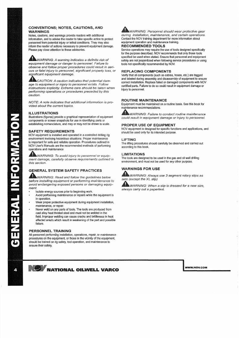
CONVENTIONS; NOTES CAUTIONS AND
WARNINGS
Notes, cautions, and warnings provide readers with
additional
information,
and to advise the
reader
to
take specific
action to
protect
personnel from potential injury or lethal conditions. They
may
also
inform the reader of actions necessary to prevent equipment damage.
Please pay
close
attention
to these
advisories.
AWARNING
A warning indicates a definite risk
of
equipment damage or danger to personnel. Fai/ure to
observe and follow
proper
procedures could result in seri-
ous
or
fatal injury to personnel, significant property loss,
or
significant equipment damage.
CAUTION: A caution indicates that potential dam-
age to equipment
or
injury
to
personnel exists. Follow
instructions explicitly. Extreme care should be taken when
performing operations
or
procedures preceded
by
this
caution.
NOTE: A note indicates that additional information is pro-
vided about the current topics.
ILLUSTRATIONS
Illustrations
(figures)
provide
graphical representation of equipment
components or screen snapshots for use in identifying parts or
establishing nomenclature, and mayor may not
e
drawn
to
scale.
SAFETY REQUIREMENTS
NOV equipment is
installed and operated in
controlled drilling
rig
environment
involving
hazardous situations.
Proper
maintenance
is important for
safe
and
reliable operation. Procedures outlined in
NOV User's Manuals are the recommended methods of performing
operations
and maintenance
WARNING:
o
avoid injury to personnel
or
equip-
ment damage, carefully observe requirements outlined
in
this section.
GENERAL SYSTEM SAFETY PRACTICES
WARNING: Read and follow the guidelines below
before installing equipment
or
performing maintenance to
avoid endangering exposed persons
or
damaging equip-
ment.
Isolate
energy sources prior to beginning work.
Avoid
performing
maintenance or repairs
while
the equipment is
in operation.
Wear
proper protective
equipment during
equipment installation,
maintenance, or repair.
Never weld on
any
parts of tools. The tools are produced from
cast alloy
heat
threted steel and
must
not
e
welded in the
field.
Improper
welding can cause cracks and
brittleness
in
heat
affected
area's which
result
in
weakening of
the part
and possible
failure.
PERSONNEL TRAINING
All personnel
perfo rmfng
installation,
operations,
repair, or maintenance
procedures
on the equipment, or those in the vicinity of the equipment,
should be
trained
on
rig
safety, tool operation,
and
maintenance
to
ensure their safety.
N TION L OILWELL V RCO
WARNING: Personnel should wear protective
gear
during installation, maintenance,
and
certain operations.
Contact the NOV training department for more information
about
equipment operation and maintenance training.
RECOMMENDED TOOLS
Service operations
may
require the use
of tools
designed
specifically
for the purpose described. NOV recommends that only
those
tools
specified be used when stated. Ensure that personnel
and
equipment
safety
are not jeopardized when following
service
procedures or
using
tools not
specifically
recommended by
NOV.
REPLACING COMPONENTS
Verify
that all
components (such as cables, hoses, etc.) are tagged
and labeled during assembly and disassembly
of
equipment to ensure
correct
installation. Replace failed
or damaged components with NOV
certified
parts.
Failure
to do so
could result
in equipment damage or
injury
to personnel.
ROUTINE MAINTENANCE
Equipment
must
be
maintained
on
routine basis. See this book
for
maintenance recommendations.
WARNING: Fai/ure to conduct routine maintenance
could result in equipment damage
or
injury
to
personnel.
PROPER USE OF EQUIPMENT
NOV equipment
is
designed
for
specific functions and
applications,
and
should
e
used only for
its
intended purpose.
LIFTING
The
lifting
procedures should
carefully
be observed and carried
out
according
to this book.
LIMITATIONS
The
tools
are
designed
to
be used
in
the gas and oil
well
drilling
environment, and
must
not be used for any
other
purpose.
WARNINGS FOR USE
WARNING: Always use segment rotary slips as
sets except the XL slip)
WARNING: When
a
slip is dressed for
a
new size,
a/ways carry out a papertest.
WWW NOV COM
7/25/2019 Rotary Care & Maintenance Handbook
http://slidepdf.com/reader/full/rotary-care-maintenance-handbook 7/116
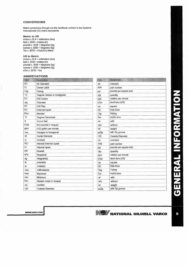
CONVERSIONS
Metric conversions through-out this handbook conform to the Systeme
Internationale
SI) metric equivalents.
Metric to US
inches x25.4 millimeters mm)
feet x .3048 meters m)
pounds x
4536
kilograms kg)
ounces
x .0283
ilograms kg)
on x
.9078
TonUS to Metric
US to Metric
inches
x25.4
millimeters
mm)
feet x
.3048
meters
m)
pounds
x .4536 ilograms
kg)
ounces
x
0283 ilograms
kg)
sTon
x .9078 on
BBREVI TIONS
WWW NOV COM
N TION L OILWELL V RCO
7/25/2019 Rotary Care & Maintenance Handbook
http://slidepdf.com/reader/full/rotary-care-maintenance-handbook 8/116
N TION L OILWELL V RCO
WWW NOV COM

7/25/2019 Rotary Care & Maintenance Handbook
http://slidepdf.com/reader/full/rotary-care-maintenance-handbook 9/116
T BLE
OF CONTENTS
WWW NOV COM
N TION L OILWELL V RCO

7/25/2019 Rotary Care & Maintenance Handbook
http://slidepdf.com/reader/full/rotary-care-maintenance-handbook 10/116
N TION L OILWELL V RCO
WWW NOV COM
7/25/2019 Rotary Care & Maintenance Handbook
http://slidepdf.com/reader/full/rotary-care-maintenance-handbook 11/116
TABLE OF CONTENTS
GENERAL INFORMATION 1
About this issue
3
The care
and
maintenance of rotary equipment
3
Patent info
3
Copyright info
3
Liability 3
Limited warranty
3
Intended audience
3
Conventions;
Notes, Cautions, and Warnings 4
Illustrations
4
Safety
Requirements
4
General System
Safety Practices
4
Personnel Training
4
Recommended Tools
4
Replacing
Components
4
Routine Maintenance
4
Proper Use
of
Equipment
4
~ ~
4
Limitations
4
Warnings for
use 4
Conversions
5
5
TABLE OF CONTENTS 7
KELLYS KELLY BUSHINGS 11
Proper
handling
of kellys
13
What
causes kelly
wear?
15
Care
of
kellys 17
Description
of
kelly drive
bushings 18
Installation 20
Operation
20
Maintenance Inspection
2
Maintenance 2
Inspection
2
Indexing a kelly
25
Drive
pin repair 26
Kelly
bushings with
drive
pin
locks 26
Kellys
and kelly
bushing parts 27
Roller kelly
bushings
29
Kelly
Bushing Parts
30
MASTER BUSHINGS
33
VARCO BJ
master
bushings
37
Maintenance
and inspection
38
Paper test: testing
of
rotary equipment wear 39
LSB Master
bushing parts
55
HAND SUPS
SDS, SDML, SDHL
and
SDXL rotary slips 59
Operation
of slips 6
Maintenance
of slips
63
Slips
inspection
63
Transmitting
torque
64
~
Inspection maintenance
procedures
78
SAFETY CLAMPS 79
Use
of
MP C safety clamps 83
Maintenance nspection 84
Detailed
instructions
for inspection
84
Detailed
instructions for maintenance 84
UFTING GEAR SUNGS 87
Quick reference
lifting
gear
and slings 89
Lifting slings for MBH1250 master
bushings
bowls PS16 90
Lifting slings for MP
MS
master bushings bowls
92
Maintenance
nspection
94
ADAPTER RINGS 1 1
APER TEST u
_____________________________________________________
0.9
WWW NOV COM
NATIONAL O.LWELL VARCO

7/25/2019 Rotary Care & Maintenance Handbook
http://slidepdf.com/reader/full/rotary-care-maintenance-handbook 12/116
N TION L OILWELL V RCO
WWW NOV COM

7/25/2019 Rotary Care & Maintenance Handbook
http://slidepdf.com/reader/full/rotary-care-maintenance-handbook 13/116
K LLYS K LLY USHINGS
WWW NOV COM
NATIONAL OIL
W LL
VARCO

7/25/2019 Rotary Care & Maintenance Handbook
http://slidepdf.com/reader/full/rotary-care-maintenance-handbook 14/116
N TION L OILWELL VARCQ
WWW NOV COM
7/25/2019 Rotary Care & Maintenance Handbook
http://slidepdf.com/reader/full/rotary-care-maintenance-handbook 15/116
KELLYS AND KELLY BUSHINGS
PROPER HANDLING OF KELLYS
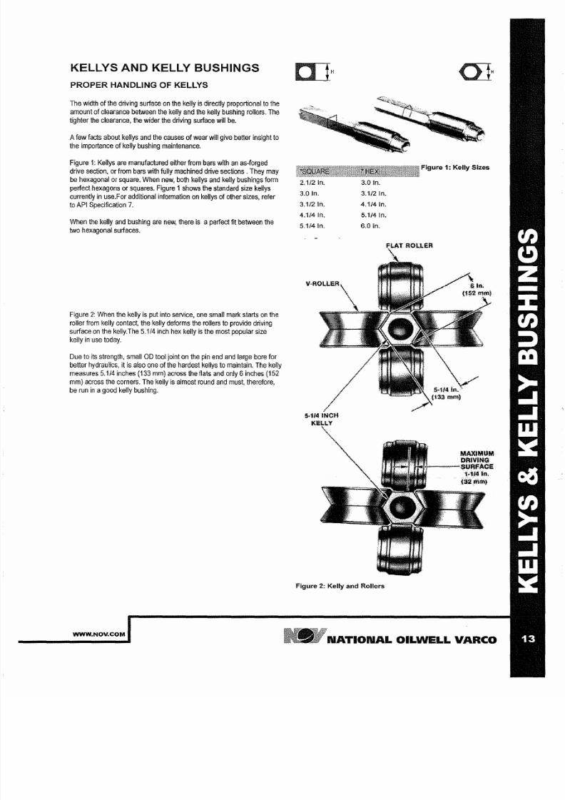
The width of the driving
surface
on the
kelly
is directly proportional to the
amount
of
clearance
between the kelly and
the kelly bushing
rollers. The
tig
hter
the
clearance,
the
wider
the driving
surface
will
be.
A
ew
facts
about
kellys and the causes of wear will give better insight to
the importance
of kelly bushing maintenance.
Figure 1:
Kellys
are manufactured
eitherfrom
bars with an as-forged
drive
section,
or
from bars with fully machined
drive
sections. They
may
be hexagonal
or square. When
new, both
kellys
and kelly
bushings
form
perfect hexagons or squares. Figure 1shows the standard size kellys
currently
in use.For
additional
information on kellys
of
other sizes, refer
to API
Specification 7.
When the
kelly
and bushing are new
there
is a
perfect
fit between the
two
hexagonal surfaces.
Figure 2: When the kelly
is
put into service, one small mark starts on the
roller
from
kelly contact, the kelly deforms the rollers to provide driving
surface
on the kelly. The
5 1/4 inch
hex kelly
is
the most
popular
size
kelly in
use today.
Due
to its
strength,
small OD tool joint
on the
pin end and large
bore
for
better hydrau
lies,
it
is
also one of the hardest kellys to maintain.
The
kelly
measures 5.114 inches
133
mm)
across
the flats and only 6
nches
152
mm) across the
corners.
The
kelly is almost
round
and must,
therefore,
be run in agood kelly bushing.
WWW.NOV.COM
2 1/2 In.
3 0 In.
3 1/2
In
4 1/4 In
5 114
In
H
3 0 In.
3 1/2 In
4 1/4
In
5 1/4 In
6 0 In
Figure 2: Kelly and Rollers
Figure : Kelly Sizes
.114
In
32rrim)
NATIONAL OILWELL VARCO
7/25/2019 Rotary Care & Maintenance Handbook
http://slidepdf.com/reader/full/rotary-care-maintenance-handbook 16/116
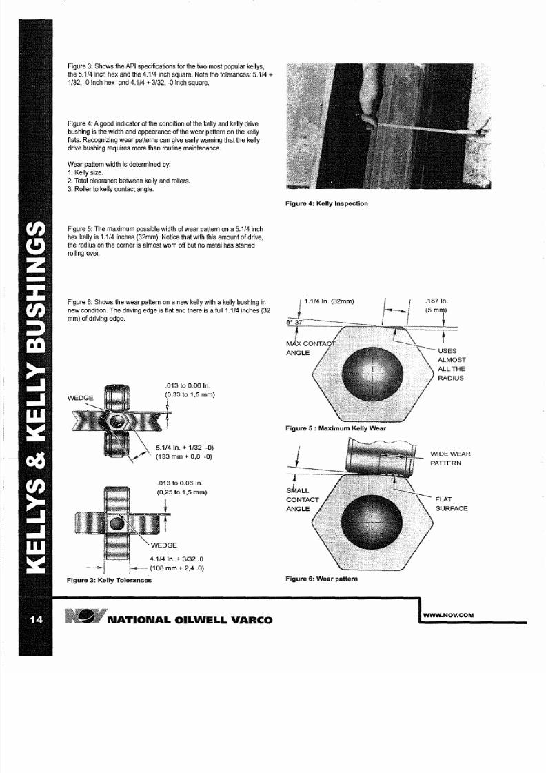
Figure
3:
Shows the API specifications for the two most popular kellys,
the 5.1/4 inch hex and the 4.1/4 inch square. Note the
tolerances:
5.1/4 +
1/32 0
inch hex
and 4.1/4 + 3/32 0
inch square.
Figure 4:
Agood indicator
of
the condition
of
the kelly and kelly drive
bushing is the width and appearance of the wear
pattern
on the kelly
flats.
Recognizing wear pattems can give
earty
warning that
the kelly
drive bushing requires more
than
routine maintenance.
Wear pattern width is determined
by:
1.
Kelly size.
2
Total clearance between kelly and rollers.
3 Roller to kelly contact angle.
Figure
5: The maximum possible
width
of
wear pattern
on a5.1/4
inch
hex
kelly
is
1.1/4 inches 32mm). Notice
that
with this amount
of
drive,
the radius on the corner is almost worn off but no metal has
started
rolling over.
Figure
6: Shows
the wear pattern
on
a
new
kelly
with
akelly bushing
in
new condition. The driving edge
is flat and
there
is
a ull 1.1/4 inches 32
mm) of driving edge.
,33
to 1,5 mm)
5.1/4
In. +
1/32 -0
133 mm + 0,8 -0)
.013 to 0.06 In.
0,25 to 1,5 mm)
4.1/4 In. + 3/32
.0
108
mm
+
2,4
.0)
igure 3: Kelly Tolerances
N TION L OILWELL V RCO
igure 4: Kelly Inspection
1.1/4 In. 32mm)
igure 5 : Maximum Kelly Wear
Figure 6: Wear pattern
WIDE WEAR
PATTERN
FLAT
SURFACE
WWW NOV COM
7/25/2019 Rotary Care & Maintenance Handbook
http://slidepdf.com/reader/full/rotary-care-maintenance-handbook 17/116
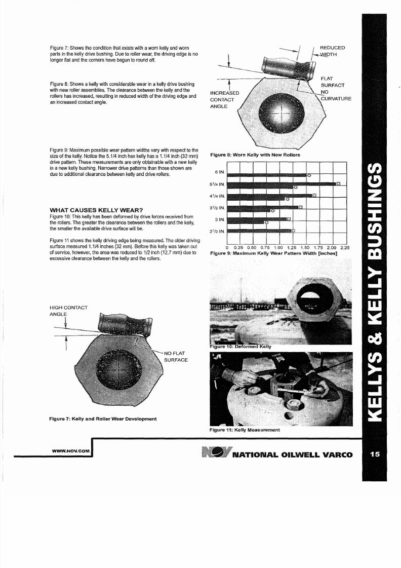
Figure 7: Shows the condition
that
exists with awom kelly and worn
parts
in
the
kelly
drive bushing. Due
to
roller
wear,
the
driving
edge
is no
longer
flat and
the comers have begun to round
off
Figure
8:
Shows akelly with considerable wear
in
akelly drive bushing
with new roller assemblies. The clearance between the kelly and the
rollers
has increased,
resulting in reduced width
of the driving
edge and
an increased
contact angle.
Figure 9: Maximum
possible
wear pattem widths vary with respect to the
size of the
kelly.
Notice the
5.1/4 inch
hex kelly
has
a 1.1/4 inch 32
mm)
drive
pattern.
These measurements
are
only obtainable
with a new kelly
in a new kelly bushing.
Narrower
drive patterns than those shown are
due to
additional clearance
between kelly
and
drive rollers.
WHAT CAUSES KELLY WEAR
Figure
10:
This kelly
has been
deformed
by
drive forces received from
the
rollers. The greater
the clearance
between the rollers and
the
kelly,
the smaller
the
available drive surface
will be.
Figure 11 shows the kelly driving edge being measured. The
older
driving
surface measured 1.1/4 inches 32 mm).
Before
this kelly
was
taken out
of service, however, the area
was
reduced to 1/2 inch 12,7 mm)
due
to
excessive
clearance
between the kelly and the
rollers.
HIGH CONTACT
Figure 7: Kelly and Roller Wear Development
WWW NOV COM
NO FLAT
SURFACE
CONTACT
ANGLE
Figure 8: Worn Kelly with New Rollers
FLAT
SURFACT
5
1
/4 IN
•••••••••
B ~ - , . - r y
4
1
/4 IN.
3
1
2 IN
•••••• ~ - ~ I . l Q L + - t - - t - - 1
IN·
••
$ - ~ ~ Y - - + - t - - t - - 1
21 2 IN. ~ R I - ~ - . - r l j I r I - ? - - + - - - 1 - - - - + - - - j
o 0 25 0 50 0 75 1 00 1 25 1 50 1 75 2 00 2 25
Figure
9:
Maximum Kelly Wear Pattern Width [inches]
Figure 11: Kelly Measurement
N TION L OILWELL V RCO
7/25/2019 Rotary Care & Maintenance Handbook
http://slidepdf.com/reader/full/rotary-care-maintenance-handbook 18/116
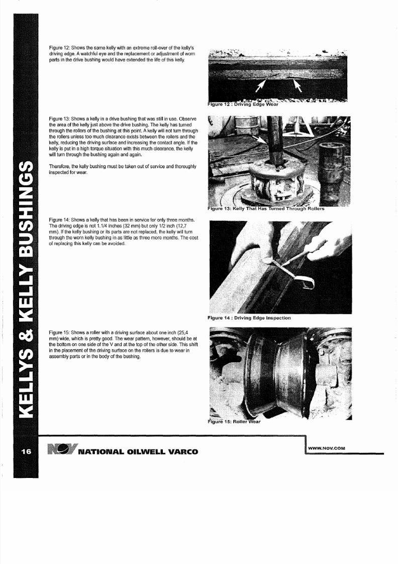
Figure
12: Shows the same
kelly with
n extreme roll-over of
the kelly s
driving
edge.
watchful eye
and
the
replacement
or adjustment of worn
parts in the drive bushing would have extended the
life of
this kelly.
Figure 13: Shows a kelly in adrive bushing that was still in
use.
Observe
the area
of
the kelly
just
above the drive bushing. The kelly has turned
through
the
rollers of the
bushing at
this
point. kelly
will
not turn
through
the rollers unless too much clearance
exists
between the rollers and the
kelly, reducing the driving surface and increasing the
contact
angle. If the
kelly is
put
in ahigh torque
situation
with
this much
clearance, the kelly
will turn through
the
bushing again
and
again.
Therefore,
the kelly bushing must
be
taken
out
of service
and
thoroughly
inspected
for
wear.
Figure 14: Shows akelly
that
has been in
service
for only three
months.
The
driving
edge
is
not 1 1/4
inches
(32 mm)
but
only
1/2 inch
(12,7
mm).
If
the kelly bushing or its parts are not replaced, the kelly will turn
through the worn kelly
bushing
in as little s three more
months.
The
cost
of
replacing this
kelly
can be avoided.
Figure
15: Shows a roller with adriving surface about
one
inch
(25,4
mm) wide, which
is
pretty good. The
wear
pattern, however, should be at
the bottom on one
side
of the Vand at the top of the other side. This
shift
in the placement of
the
driving surface
on
the rollers is due to wear
in
assembly parts or in the body
of
the bushing.
NATIONAL OILWELL VARCO
Figure 4 Driving Edge Inspection
WWW NOV COM
7/25/2019 Rotary Care & Maintenance Handbook
http://slidepdf.com/reader/full/rotary-care-maintenance-handbook 19/116
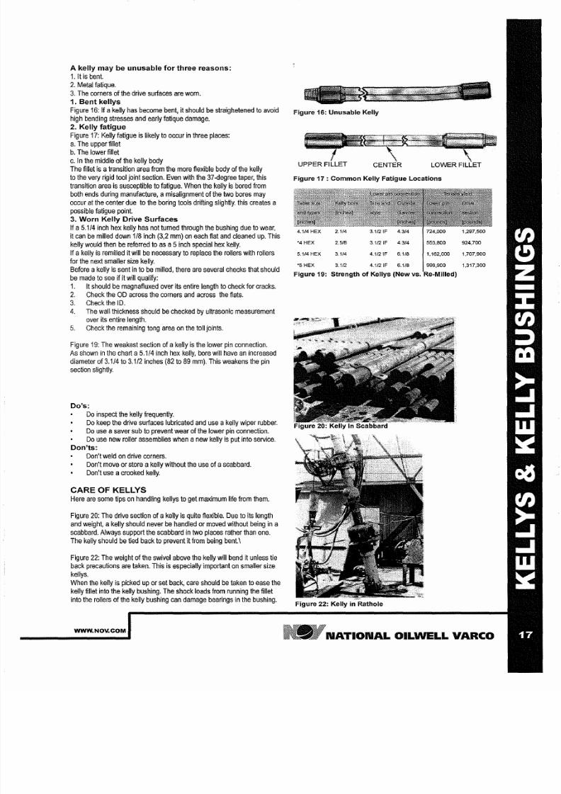
A kelly may be unusable
for
three reasons:
1.lt s
bent.
2
Metal fatique.
3 The corners
of
the
drive
surfaces are worn.
1
Bent kellys
Figure 16:
If
akelly
has become
bent, it
should be
straighetened
to
avoid
high bending
stresses
and
early fatique
damage.
2 Kelly fatigue
Figure
17: Kelly
fatigue is
likely to
occur
in
three
places:
a The upper fillet
b The lower
fillet
c In
the middle of
the kelly
body
The
fillet
is a ransition
area from the
more flexible
body of the kelly
to the
very rigid tool
joint
section. Even
with the
37-degree taper, this
transition area is susceptible to fatigue. When the kelly
is
bored from
both ends
during manufacture,
amisalignment
of
the
two bores may
occur at
the
center due
to
the boring tools drifting slightly.
this
creates a
possible
fatigue point.
3
Worn Kelly Drive Surfaces
If a5 1/4 inch hex kelly
has not
turned through the bushing due
to
wear,
it can
be
milled down 1/8 inch (3,2 mm) on each
flat
and cleaned
up.
This
kelly
would then
be
referred to
as
a 5
nch
special
hex
kelly.
If
a kelly is remilled it
will
be necessary
to replace
the
rollers
with
rollers
for the next smaller size
kelly.
Before akelly
is sent
in to
be milled, there are
several checks
that should
be
made to see
if it
will
qualify:
1. It
should be magnafluxed over its entire length to check for cracks.
2 Check the OD across the
corners
and across the flats.
3
Check
the
ID.
4. The
wall thickness should be checked by ultrasonic measurement
over its entire length.
5 Check the remaining tong area on the toll joints.
Figure
19: The
weakest section of
akelly is the
lower
pin connection.
As shown
in the
chart
a5 1/4 inch hex
kelly,
bore will
have
an increased
diameter of
3 1/4
to 3 1/2 inches (82 to 89 mm). This
weakens
the pin
section slightly.
Do s:
Do inspect the
kelly frequently.
Do keep
the
drive surfaces lubricated
and use
a kelly wiper rubber.
Do
use
asaver sub to prevent wear of the lower pin
connection.
Do
use
new roller
assemblies
when
anew kelly
is
put
into
service.
Don ts:
Don t weld on drive corners.
Don t
move
or store
a kelly without the use of a
scabbard.
Don t use acrooked kelly.
CARE OF KELLYS
Here are some tips
on
handling kellys to
get
maximum life
from them.
Figure
20: The
drive section of
a kelly
is quite flexible. Due
to its length
and
weight, akelly should never be handled or moved without
being
in a
scabbard. Always support the scabbard in two places
rather
than one.
The
kelly should be tied back to
prevent
it from
being bent.\
Figure
22:
The weight of the swivel above the kelly will
bend
it
unless
tie
back
precautions
are taken.
This
is especially
important
on smaller
size
kellys.
When the
kelly is
picked
up
or set back, care should be taken
to ease the
kelly fillet into the kelly bushing. The
shock
loads from running the fillet
into
the rollers of
the kelly
bushing
can
damage bearings in the bushing.
WWW.NOV.COM
Figure 16: Unusable Kelly
Figure 17 : Common Kelly Fatigue Locations
4.114
HEX
2.114
3 112 IF
4.314
724,000 1,297,500
4
HEX
2.516
3.1/2
IF 4.314
553,600 924,700
5.114
HEX
3.114 4.1/2
IF
6.116 1,162,000 1,707,900
5
HEX 3.112 4.1/2
IF
6.118 999,900 1,317,300
Figure 19: Strength
of
Kellys (New vs.
~ ' . Z ; : : ; . ~ .
~ ; :
w
Figure 22: Kelly
in
Rathole
N TION L OILWELL V RCO
7/25/2019 Rotary Care & Maintenance Handbook
http://slidepdf.com/reader/full/rotary-care-maintenance-handbook 20/116
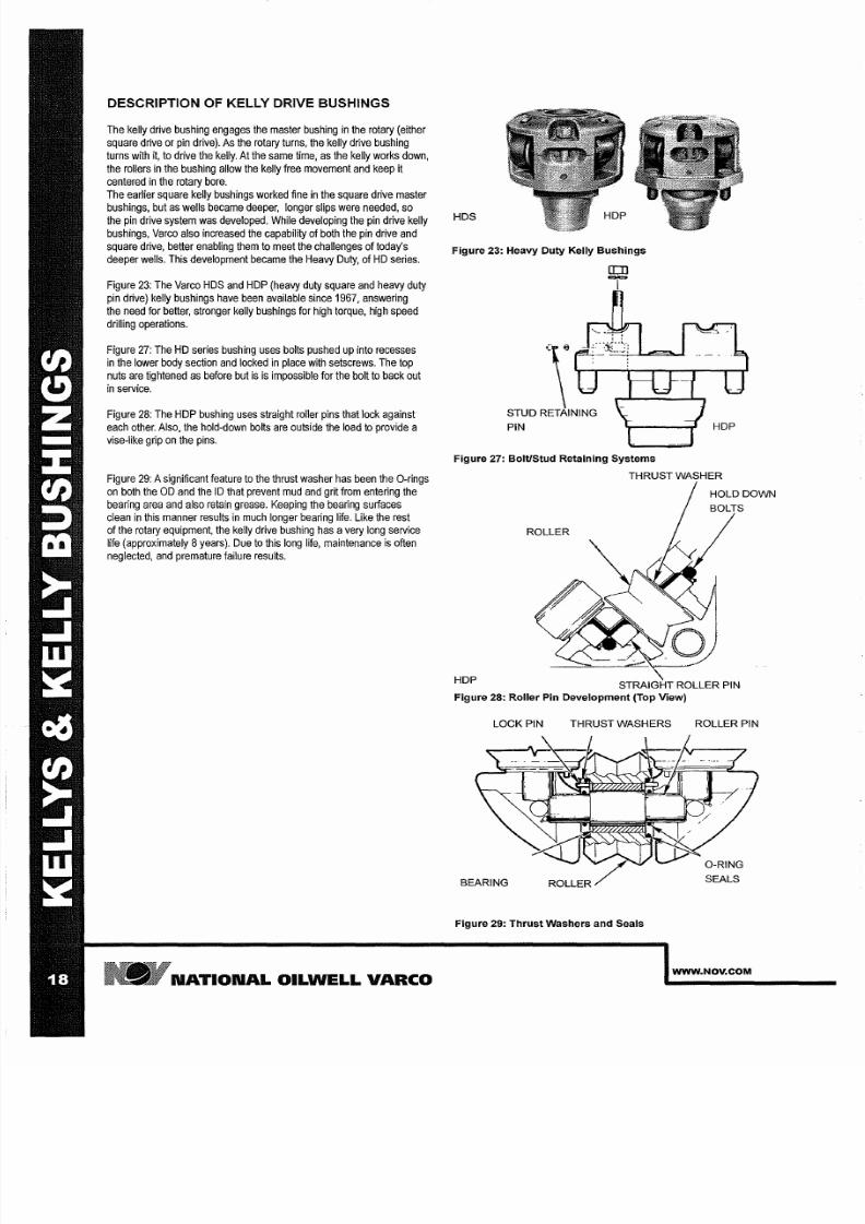
DESCRIPTION OF KELLY DRIVE BUSHINGS
The
kelly drive
bushing engages the
master
bushing
in
the
rotary
(either
square
drive
or pin drive).
As
the rotary turns, the kelly drive bushing
turns
with it, to drive the kelly.
At
the same time, as the kelly works down,
the rollers in the bushing allow
the
kelly
free
movement and keep it
centered
in the rotary
bore.
The earlier square kelly bushings worked fine in the
square
drive master
bushings,
but
as wells became deeper,
longer slips
were needed, so
the pin drive
system was developed. While developing
the pin
drive kelly
bushings, Varco also increased the capability
of
both the
pin
drive and
square drive, better enabling them to meet the
challenges
of
today s
deeper
wells. This
development
became the Heavy
Duty,
of HD series.
Figure
3:
The Varco HDS and HDP (heavy duty
square
and heavy
duty
pin
drive)
kelly bushings have been
available since
1967, answering
the need
for better, stronger
kelly bushings
for high
torque, high speed
drilling
operations.
Figure
27: The HD series
bushing
uses bolts pushed up
into
recesses
in
the
lower body section
and
locked in place with
setscrews.
The top
nuts are tightened
as
before but
is is
impossible for
the
bolt
to
back
out
in
service.
Figure
8:
The HDP bushing uses straight roller pins that lock
against
each
other.
Also,
the hold-down
bolts
are outside
the load
to
provide a
vise-like grip on
the pins.
Figure 9: Asignificant feature to the thrust washer has been the O-rings
on both the OD and the
ID
that
prevent
mud and grit from
entering
the
bearing area
and
also retain grease. Keeping the
bearing surfaces
clean
in
this manner results in
much
longer bearing life. Like the rest
of
the rotary eqUipment, the kelly drive bushing has avery long
service
life (approximately
8
years).
Due to this long
life, maintenance
is often
neglected, and premature failure results.
N TION L OILWELL
V RCO
HDS
Figure 23: Heavy Duty Kelly Bushings
\
TUD RETAINING
PIN
rr:n
Figure 27: Bolt/Stud Retaining Systems
THRUST WASHER
HOLD
DOWN
ROLLER
\
DP
STRAIGHT ROLLER PIN
Figure 28: Roller Pin Development Top View)
LOCK PIN THRUST WASHERS
BEARING ROLLER
Figure 29: Thrust Washers and Seals
ROLLER PIN
O RING
SEALS
WWW NOV COM
7/25/2019 Rotary Care & Maintenance Handbook
http://slidepdf.com/reader/full/rotary-care-maintenance-handbook 21/116
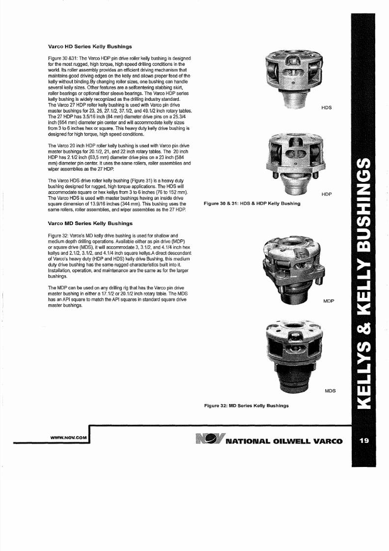
Varco
H
Series Kelly Bushings
Figure
30 31: The
Varco
HOP
pin drive
roller
kelly bushing is
designed
for the most
rugged,
high torque, high
speed drilling
conditions
in the
world. Its roller
assembly
provides an efficient driving mechanism
that
maintains
good driving edges on the kelly and allows proper feed of the
kelly
without binding.By
changing
roller
sizes,
one
bushing can handle
several kelly
sizes.
Other features are aseifcentering
stabbing skirt,
roller bearings or optional fiber sleeve bearings. The Varco HOP
series
kelly bushing is widely recognized as the drilling
industry
standard.
The Varco 27 HOP
roller
kelly
bushing
is used
with
Varco pin drive
master
bushings for 23,26, 27.1/2 37.1/2
and 49.1/2
inch rotary tables.
The 27 HOP has 3 5116 inch (84 mm) diameter drive
pins
on a25.3/4
inch (654 mm) diameter pin
center
and will accommodate kelly
sizes
from 3
o
6 nches hex or square. This
heavy
duty
kelly drive
bushing
is
designed
for
high torque, high speed conditions.
The Varco 20
inch
HOP roller
kelly bushing
is
used with
Varco pin
drive
master bushings
for
20.1/2 21, and
22
inch rotary tables. The 20 inch
HOP has
2 112 inch
(63,5 mm)
diameter drive
pins on a23
inch
(584
mm) diameter
pin center. It uses the same
rollers,
roller
assemblies
and
wiper assemblies
as
the
27
HOP.
The Varco HOS
drive roller
kelly
bushing (Figure
31) is
a
heavy
duty
bushing designed for rugged, high torque
applications. The
HOS will
accommodate square
or hex kellys from 3 o 6 nches (76 to 152
mm).
The Varco HOS is
used with master
bushings having an inside
drive
square dimension
of
13.9/16 inches (344 mm). This bushing
uses the
same rollers, roller assemblies, and
wiper
assemblies
as
the 27
HOP.
Varco M Series Kelly Bushings
Figure
32: Varco's
MO kelly drive
bushing
is used for shallow and
medium depth drilling operations.
Available
either
as
pin drive (MOP)
or
square
drive (MOS), it will
accommodate 3 3.1/2 and 4.1/4 inch hex
kellys
and
2.1/2 3.1/2
and
4.1/4
inch
square kellys.A
direct descendant
of Varco's heavy duty (HOP and HOS) kelly drive Bushing, this medium
duty
drive bushing has
the
same rugged
characteristics built into
it.
Installation, operation, and
maintenance
are the same
as
for the larger
bushings.
The MOP can
be used on
any
drilling rig that has the
Varco pin
drive
master bushing in either a 17.1/2 or 20.1/2 inch rotary table. The MOS
has an API
square
to match the API squares
in
standard square
drive
master
bushings.
WWW NOV COM
Figure 30 31: HOS HOP Kelly ushing
MDS
Figure 32:
MO
Series Kelly
ushings
N TION L OILWELL V RCO
7/25/2019 Rotary Care & Maintenance Handbook
http://slidepdf.com/reader/full/rotary-care-maintenance-handbook 22/116
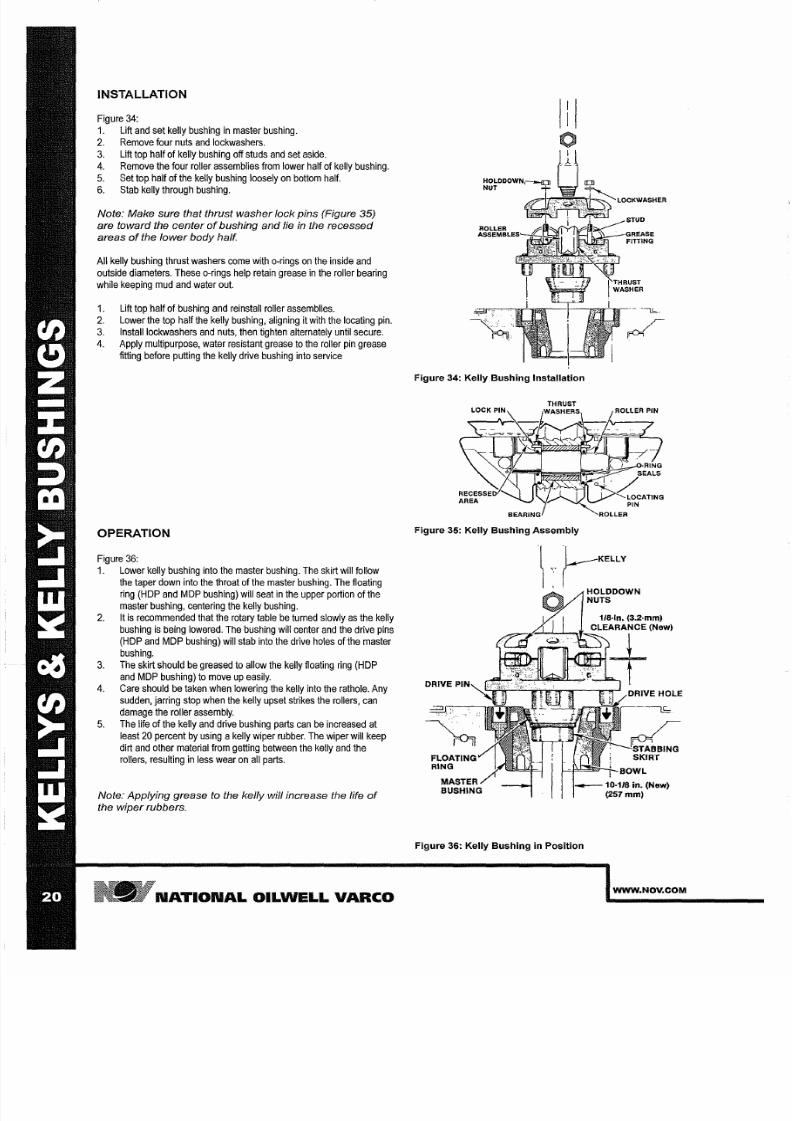
INSTALLATION
Figure 34:
1.
Lift
and set
kelly
bushing in
master
bushing.
2
Remove four
nuts
and
lockwashers.
3. Lift top half of kelly bushing off
studs
and set aside.
4 Remove the four
roller assemblies from lower
half of kelly bushing.
5. Set
top
half
of the kelly
bushing loosely on bottom
half.
6. Stab kelly through bushing.
Note: Make sure that thrust washer lock pins Figure 35)
are toward the center
o
bushing and lie
n
the recessed
areas
o
the
low r
body half.
All kelly bushing
thrust washers come
with
o-rings on
the inside
and
outside diameters. These o-rings help retain grease in the roller bearing
while keeping mud and
water
out.
1.
Lift
top half of
bushing and
reinstall
roller assemblies.
2
Lower
the top half the kelly bushing, aligning it with the
locating
pin.
3 Instalilockwashers and nuts, then
tighten alternately
until secure.
4.
Apply
multipurpose, water resistant
grease
to
the
roller
pin
grease
fitting before putting the kelly
drive
bushing into
service
OPERATION
Figure
36:
1. Lower kelly bushing
into the master
bushing. The skirt
will follow
the taper down into the throat of
the
master bushing.
The
floating
ring HOP and MOP bushing) will seat in the upper portion of the
master bushing,
centering the kelly bushing.
2. It
is
recommended that the
rotary
table be turned slowly
as the
kelly
bushing
is
being lowered. The bushing will
center
and the drive pins
HOP and MOP bushing)
will
stab into
the drive
holes
of the master
bushing.
3. The skirt should be greased
to
allow the kelly floating ring
HOP
and MOP
bushing)
to move up easily.
4. Care
should
be taken when lowering
the
kelly into the rathole. Any
sudden, jarring stop when the kelly upset strikes the rollers, can
damage the roller assembly.
5. The life
of the kelly and
drive bushing parts
can be increased
at
least 20 percent by using a
kelly
wiper
rubber. The
wiper will keep
dirt and other
material
from
getting
between the kelly and the
rollers, resulting in
less
wear
on all
parts.
Note: Applying grease to the kelly will increase the life
o
the wiper rubbers.
N TION L
OILWELL V RCO
III
o
Figure 34: Kelly Bushing Installation
Figure 35: Kelly Bushing Assembly
l :L KELLY
I
Figure 36: Kelly Bushing n Position
HOLDDOWN
NUTS
WWW NOV COM

7/25/2019 Rotary Care & Maintenance Handbook
http://slidepdf.com/reader/full/rotary-care-maintenance-handbook 23/116
MAINTENANCE INSPECTION
MAINTENANCE
Figure 36:
1 Tighten
holddown
nuts weekly.
2 Grease roller assembly
daily
at four fittings.
3 Grease stabbing skirt
for
ease of
stabbing.*
4.
Replace
drive
pins when bottom
taper
is too worn
to
aid
in
stabbing.
5
Replace the
drive
hole bushing in
master
bushing when
worn
to
an egg shape.
6 Replace API drilling
bowl
when wear
in
throat area exceeds
10 7/8 inches
276 mm). Proper throat size is necessary for good
stabbing.
7
Between the top
and bottom
body halves there
should be
1/8
inch 3,2 mm)
clearance;
if
there
is none,
worn journals are
indicated
and the kelly bushing should be replaced.
• HOP
and
MOP
bushings.
INSPECTION
Figure 37 38 and
further:
Weekly
inspection
of the kelly bushing
is
performed as follows:
1 Check to see if
top nuts are
tight.
2 Use a pry bar to check for body wear
and
roller assembly
wear.
3 Check
clearance
between rollers and kelly.
4
Check rollers and
assemblies for wear.
5 Check the body for
wear.
WWW NOV COM
SLEEVE BEARING
ROLLER
BEARING
OPTIONAL
ROLLER PIN
V-ROLLER
~ H R U S T W S H E R
Figure 37: Typical Kelly
Bushing Roller ssembly
5 0 in.
381
mm)
~ i
14 25
in.
(362
mm)
i
Figure 39: Typical Square Drive
Kelly Bushing
N TION L OILWELL V RCO
7/25/2019 Rotary Care & Maintenance Handbook
http://slidepdf.com/reader/full/rotary-care-maintenance-handbook 24/116
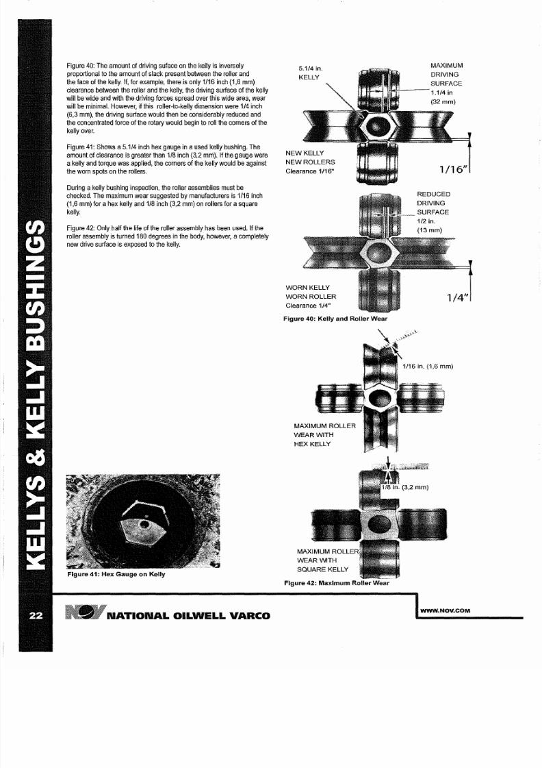
Figure 40: The amount of driving suface on the kelly is inversely
proportional to the amount of
slack present
between the
roller
and
the
face
of the kelly.
If,
for example,
there s only
1/16 inch
1,6 mm)
clearance between the roller
and
the kelly, the driving surface
of
the kelly
will be wide and with the driving
forces
spread over this wide area, wear
will be minimal.
However,
if this roller-to-kelly dimension
were
1/4
inch
6,3
mm),
the
driving
surface would then
be
considerably
reduced
and
the
concentrated
force of the rotary would begin to roll the
comers
of the
kelly over.
Figure 41: Shows a5 1/4 inch hex gauge in a
used
kelly bushing. The
amount of
clearance
is greater than 1 8
inch
3,2 mm). If the gauge were
akelly and torque
was
applied, the corners of
the
kelly would be against
the worn
spots
on the rollers.
During
akelly bushing inspection,
the roller assemblies
must be
checked. The maximum
wear suggested by
manufacturers
is
1/16 inch
1,6 mm) for ahex kelly and 1 8 inch 3,2 mm) on rollers for asquare
kelly.
Figure 42: Only half the life
of
the roller
assembly has been
used. If the
roller
assembly
is
turned 180 degrees
n
the
body,
however,
a
completely
new
drive
surface
is
exposed
to the kelly.
Figure 41: Hex Gauge on Kelly
N TION L OILWELL V RCO
5.1/4
in.
KELLY
NEW KELLY
NEW ROLLERS
Clearance 1/16
WORN
KELLY
WORN ROLLER
Clearance
1/4
Figure 40: Kelly and Roller Wear
MAXIMUM ROLLER
WEAR WITH
HEX KELLY
SQUARE
KELLY
Figure 42: Maximum Roller Wear
MAXIMUM
DRIVING
SURFACE
1.1/4
in
32 mm)
1/16
REDUCED
DRIVING
1/4
1/16 in. 1,6 mm
WWW NOV COM
7/25/2019 Rotary Care & Maintenance Handbook
http://slidepdf.com/reader/full/rotary-care-maintenance-handbook 25/116
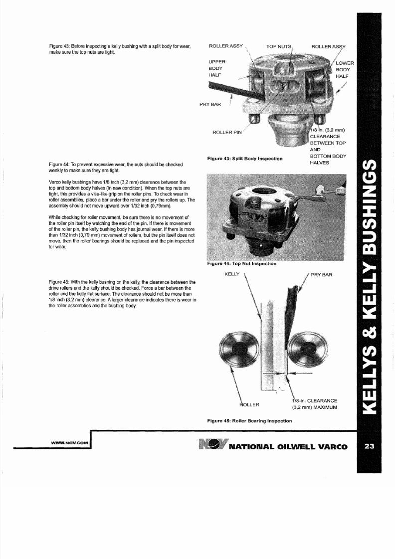
Figure 43: Before inspecting
a
kelly
bushing
with
asplit
body
for
wear,
make sure the top nuts
are tight.
Figure
44:
o
prevent
excessive wear, the
nuts
should be checked
weekly
to make
sure
they are
tight.
Va
reo
kelly bushings have 1 8 inch 3,2 mm) clearance between the
top and
bottom
body halves in new condition). When the top nuts are
tight,
this provides
a
vise-like
grip on the roller pins. o check
wear
in
roller
assemblies, place
a
bar under the roller and pry the rollers up. The
assembly should not move upward over 1 32
inch
0,79mm).
While checking
for
roller movement,
be
sure there is no movement of
the roller pin
itself
by watching the end of the pin.
If
there
is
movement
of
the
roller pin,
the
kelly bushing body has journal wear.
If
there is
more
than 1 32 inch 0,79
mm)
movement
of rollers,
but the
pin
itself does not
move, then the roller bearings should be
replaced
and the pin
inspected
for wear.
Figure 45:
With
the kelly
bushing
on the
kelly,
the clearance between
the
drive rollers
and
the
kelly
should
be
checked. Force
a
bar between the
roller
and the kelly flat
surface.
The clearance
should
not be more than
1 8
inch
3,2
mm)
clearance.
A
arger clearance
indicates
there is wear
in
the roller assemblies
and
the bushing
body.
WWW NOV COM
ROLLER ASSY ,
UPPER
BODY
HALF
PRY BAR
ROLLER PIN
Figure 4 : Split Body Inspection
Figure 44: Top Nut Inspection
KELLY
Figure 45: Roller Bearing Inspection
BETWEEN TOP
AND
BOTTOM BODY
HALVES
CLEARANCE
N TION L OILWELL V RCO
7/25/2019 Rotary Care & Maintenance Handbook
http://slidepdf.com/reader/full/rotary-care-maintenance-handbook 26/116
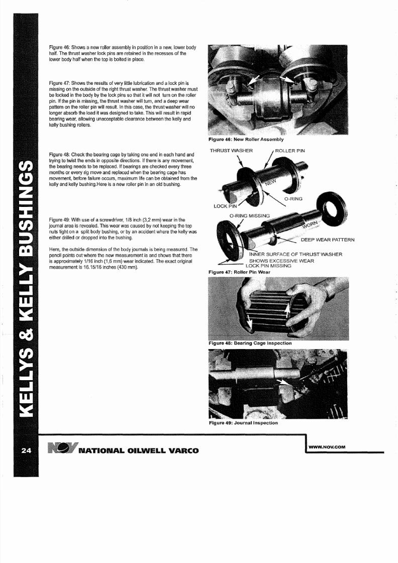
Figure 46: Shows a
new
roller
assembly
in
position
in a
new
lower
body
half.
The
thrust washer lock pins
are
retained
in
the recesses
of
the
lower body half when the top is bolted in place.
Figure
47: Shows the
results
of very little
lubrication
and a ock pin
is
missing on the
outside
of the
right thrust
washer. The thrust
washer must
be locked
in the body by the lock pins
so
that it
will not
turn
on
the roller
pin.
If
the pin is missing, the thrust
washer
will turn, and a
deep wear
pattern
on
the roller
pin
will result.
In this
case,
the thrust
washer will
no
longer absorb the
load
it was designed to
take. This
will
result in rapid
bearing wear, allowing unacceptable clearance
between the kelly and
kelly bushing
rollers.
Figure
48: Check the
bearing
cage
by taking
one end
in
each hand and
trying
to twist the ends in opposite directions.
If
there
is any movement,
the bearing
needs
to be replaced. If
bearings
are checked
every three
months or
every
rig
move
and
replaced when the bearing
cage
has
movement, before failure occurs, maximum life can be
obtained
from the
kelly and kelly
bushing.Here
is
a new
roller
pin in an old bushing.
Figure
49:
With
use
of
ascrewdriver,
1/8 inch
3,2
mm) wear
in the
journal area is revealed. This wear
was
caused
by not
keeping the
top
nuts tight
on
a
split
body bushing, or by
an
accident where the kelly was
either
drilled
or dropped into the bushing.
Here, the outside
dimension
of the body journals
is
being measured. The
pencil paints out
where
the new measurement
is
and shows that
there
is
approximately
1/16
inch 1,6
mm)
wear indicated.
The
exact
original
measurement
is
16 15/16 inches 430 mm).
N TION L OILWELL
V RCO
Figure 6: New Roller Assembly
DEEP WEAR PATTERN
SHOWS EXCESSIVE WEAR
: : : ; LOCK PIN MISSING
Figure 7: Roller Pin Wear
Figure 9: Journal Inspection
WWW NOV COM

7/25/2019 Rotary Care & Maintenance Handbook
http://slidepdf.com/reader/full/rotary-care-maintenance-handbook 27/116
Figure 50: Shows maximum allowable wear dimensions across
outside
journal
areas.
This type of inspection can be
done
to
determine
body
wear or
spread
in
the
body. Spread
in
the body of the kelly bushing
itself
can
occur
if the total weight of the upper
fillet of
the kelly
is
in the rollers
of the kelly bushing. This
situation
can occur
if
there is abreak in one of
the
tool
jOints above the body of
the
kelly. If
this
does
happen the
kelly
bushing body
and
assemblies must
be
inspected
for damage as
soon
as
possible.
INDEXING KELLY
Figure
5 :
Shows the difference in the condition of the corners of the
kelly. The
corners
that
are against the
flat rollers
are rolled over more
than the corners that
are in the Vof the other two rollers.
What
has
happened
is that the driving action
of the
bushing has forced
the corner
against
both
sides of
the V-roller. This
action has pressed the
metal in the V-shape.
Indexing the
kelly will extend the life
of the
kelly
by
30
to 40
percent if
it
is
indexed after every
rig
move when the kelly
is
broken down or once
every
three months
whichever
comes
first.
To
index
the kelly remove the top nuts on the bushing lift the top and
remove the roller assemblies. Turn
the
kelly in the
bushing
1 6
of
a
urn
so that the two corners which were against the flat rollers are
now
in the
Vof the other rollers. Longer roller assembly life can be achieved
by
turning
the roller
assemblies 180
degrees
in the bushing
body each
time
the kelly is
indexed.
Lower the
top
and
tighten the nuts alternately until it
is
secure using a hammer wrench.
WWW NOV COM
measurement
Figure 50: Outside Journal Measurement
INCREASED
DRIVE ANGLE
REDUCED
DRIVE
ANGLE
ARE ROTATED 180
WITHIN
THE BUSHING TO PRESENT
NEW DRIVE SURFACES
Figure 51: Indexed Kelly
REDUCED
DRIVE
SURFACE
INCREASED
DRIVE
SURFACE
INDEXED 1 6
TURN ROLLED
OVER EDGE
WILL BE
PRESSED IN
V OF
ROLLER
N TION L OILW LL V RCO
7/25/2019 Rotary Care & Maintenance Handbook
http://slidepdf.com/reader/full/rotary-care-maintenance-handbook 28/116
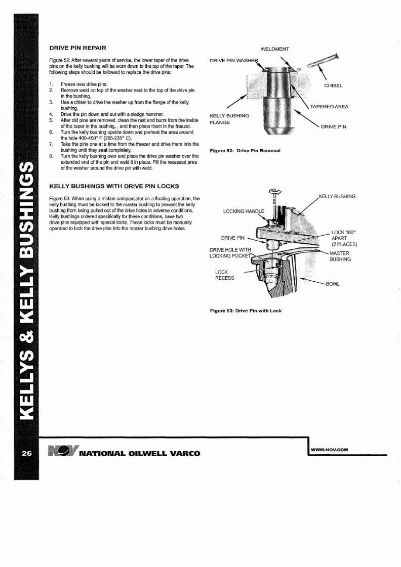
DRIVE PIN REP IR
Figure 52: After several
years
of service, the lower taper
of the
drive
pins on the kelly bushing will be worn
down
to the top
of
the taper. The
following steps should
be followed to replace the
drive pins:
1 Freeze new
drive
pins.
2. Remove weld on top of the
washer
next to the top of the
drive
pin
in
the bushing.
3. Use
a
chisel to drive
the
washer up from the flange of the kelly
bushing.
4.
Drive the pin down and
out with
a
sledge hammer.
5.
After old pins are
removed,
clean
the
rust
and
burrs
from the
inside
of the taper in the bushing, and then place them in the freezer.
6. Turn the
kelly
bushing upside down and
preheat
the area around
the hole 400-450°
F
205-235° C .
7.
Take
the pins one at
a
ime from
the
freezer and drive them into the
bushing until they seat completely.
8.
Turn
the kelly bushing
over
and place
the drive
pin
washer over
the
extended end
of the
pin
and
weld
it in place. Fill the recessed area
of
the washer around the
drive
pin with weld.
KELLY BUSHINGS WITH DRIVE PIN LOCKS
Figure 53: When using
a
motion compensator
on a loating operation,
the
kelly
bushing must be locked to the
master
bushing to prevent the kelly
bushing from being pulled
out
of the drive holes in adverse
conditions.
Kelly bushings ordered specifically for these conditions, have two
drive pins
equipped
with
special
locks. These locks
must
be
manually
operated
to
lock
the
drive pins into the master
bushing
drive holes.
N TION L OILWELL V RCO
KELLY BUSHING
FLANGE
WELDMENT
Figure 5 : Drive Pin Removal
LOCK
RECESS
Figure 53: Drive Pin with Lock
KELLY BUSHING
LOCK
180°
APART
2
PLACES)
MASTER
BUSHING
WWW NOV COM
7/25/2019 Rotary Care & Maintenance Handbook
http://slidepdf.com/reader/full/rotary-care-maintenance-handbook 29/116
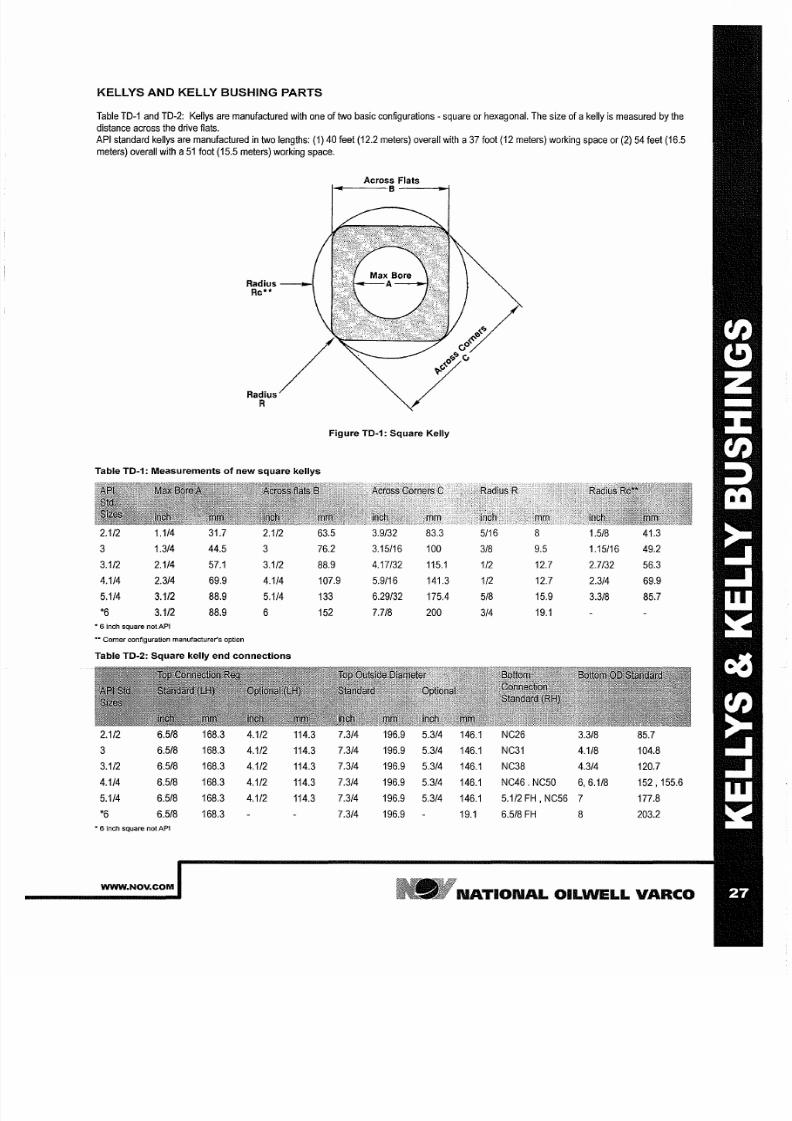
KELLYS
AND
KELLY BUSHING PARTS
Table
TD-1
and
TD-2:
Kellys are manufactured with one of two basic
configurations
- square or hexagonal. The
size of
akelly
is
measured by the
distance
across the drive flats.
API standard kellys
are manufactured in two
lengths:
1) 40
feet
12.2 meters) overall with a37 foot 12 meters) working space or 2) 54 feet 16.5
meters) overall with a51 foot 15.5 meters) working space.
Across Flats
...
·B J
d i u s -
c··
R
Figure TD 1: Square Kelly
Table TD 1: Measurements
of
new square kellys
2.1/2
1.1/4
31.7 2.1/2 63.5
3.9/32
83.3 5/16 8
1.5/8
41.3
3 1.3/4
44.5
3
76.2
3.15/16
100
3/8
9.5
1.15/16 49.2
3 112
2.1/4
57.1
3.1/2 88.9 4.17/32 115 1 1/2 12.7 2.7/32 56.3
4.1/4
2.3/4
69.9
4.1/4
107.9
5.9/16
141.3
1/2 12.7
2.3/4 69.9
5.1/4
3.1/2
88.9
5.1/4
133
6.29/32
175.4
5/8
15.9
3 318
85.7
*6
3.1/2
88.9 6 152 7.7/8 200
3/4
19.1
• 6 inch square not API
Carner configuration
manufacturer s
option
Table TD 2: Square kelly end connections
2.1/2 6.5/8
168.3
4.1/2 114.3
7.3/4
196.9 5.3/4
146.1 NC26 3.3/8
85.7
3
6.5/8
168.3
4.1/2
114.3
7.3/4
196.9
5.3/4
146.1 NC31
4.1/8
104.8
3.1/2 6.5/8
168.3
4.1/2 114.3
7.3/4
196.9 5.3/4 146.1 NC38 4.3/4 120.7
4.1/4 6.5/8
168.3
4.1/2
114.3
7.3/4
196.9
5.3/4
146.1
NC46. NC50 6 6.1/8
152,155.6
5.1/4
6.5/8
168.3 4.1/2
114.3
7.3/4 196.9
5.3/4 146.1
5.1/2
FH
NC56
7 177.8
*6
6.5/8 168.3 7.3/4 196.9
19.1
6.5/8
FH
8
203.2
· nch square not API
WWW NOV COM
NATIONAL
OILWELL
VARCO
7/25/2019 Rotary Care & Maintenance Handbook
http://slidepdf.com/reader/full/rotary-care-maintenance-handbook 30/116
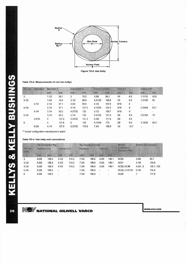
Radius
Radius ----iO-
Rc··
Table TO 3: Measurements of new hex kellys
1 1/2
38.1
3 112
1 3/4 44.5
3 1/2
3 112 2 1/4 57 1 3 3/4
4 1/4 2 1/4
57.1
4 1/4
4 114
3 1/4 82.5 4 27/32
5 1/4 3 1/4
82.5
5 1/4
5 9116
4
101.6 5 31/32
6 4
101.6
6
6 518
4 1/4
107.9
6 27/32
** Corner configuration manufacturer s option
Table TO 4: Hex kelly end connections
6 5/8
168.3
4 1/2
114.3
3 1/2 6 5/8 168.3 4 1/2 114.3
4 1/4 6 5/8
168.3 4 112
114.3
5 1/4
6 5/8 168.3
6
6 5/8 168.3
Across Flats
Figure TO 2: Hex Kelly
76.2 3 3/8
88.9
3 31/32
95.6
4 1/4
107.9 4 13/16
123 5 112
133
5 31/32
151.3
6 3/8
152 6 13/16
173.8
7 3/4
7 3/4 196.9
5 3/4
7 3/4 196.9 5 3/4
7 3/4 196.9 5 3/4
7 3/4 196.9
7 3/4 196.9
N TION L
OILWELL
V RCO
85.7
1/4
6.3
1 11/16 42.9
100.8
1/4
6.3
1 31/32
50
107.9 5/16 8
122.2 5/16
8 2 25/64
60.7
139.7 5/16
8
151.3
3/8
9.5
2 61/64
75
171.5 3/8
9.5
173 3/8
9.5
3 13/32 86.5
196.9
1/2 12.7
146.1
NC26 3 3/8 85.7
146.1 NC31
4 1/8 104.8
146.1 NC38,
NC46 4.3/4 6
120.7,152
NC50,
5 1/2
FH
6 1/8
155.6
NC56
7
177.8
WWW NOV COM
7/25/2019 Rotary Care & Maintenance Handbook
http://slidepdf.com/reader/full/rotary-care-maintenance-handbook 31/116
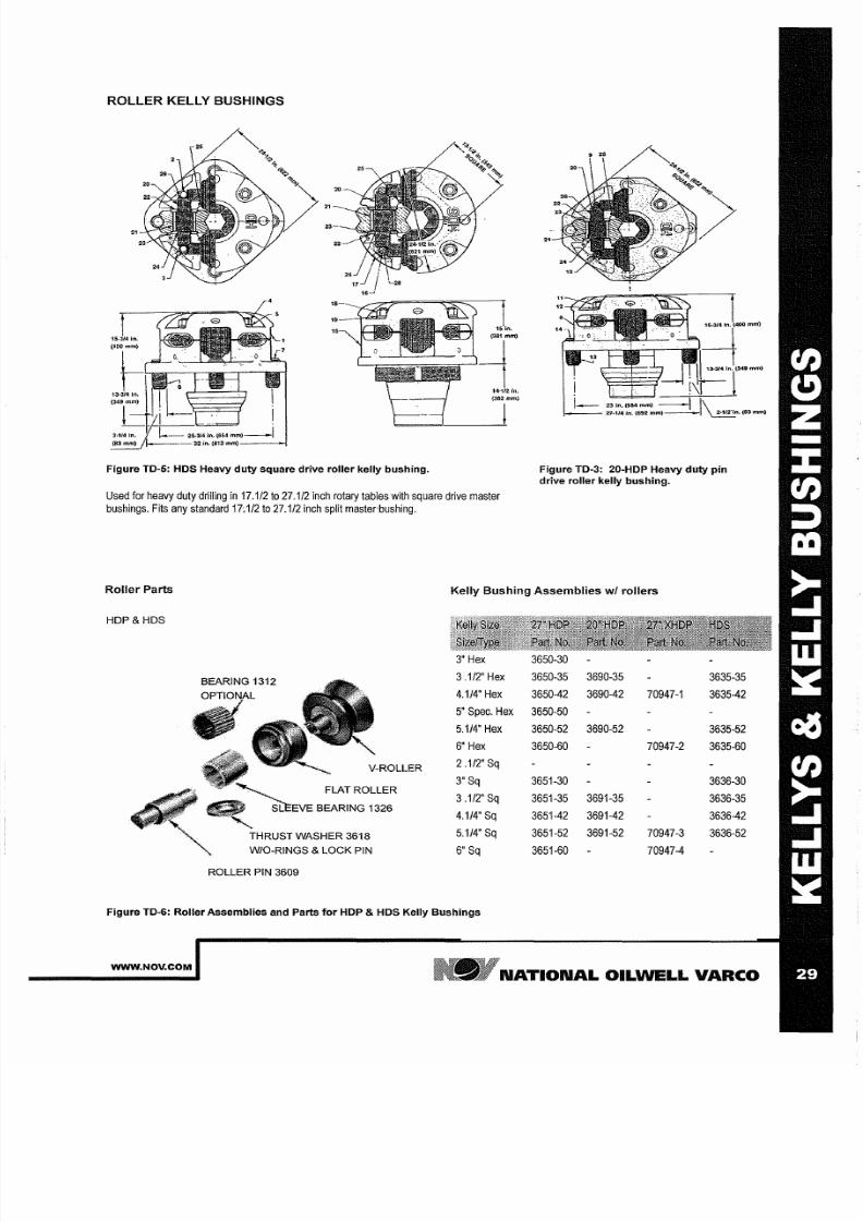
ROLLER KELLY BUSHINGS
Figure TO-5: HOS Heavy duty square drive roller kelly bushing.
Used for heavy duty drilling
in
17.1/2
to
27.1/2
inch rotary
tables
with square drive master
bushings.
Fits any standard 17.1/2
to
27.1/2 inch
split
master bushing.
mm)
mm)
_
20 in.
584
mm) \
27·114 In
(692 m m -_
~ n
(83
mm
Figure TO-3: 20-HOP Heavy duty pin
drive roller kelly bushing.
Roller Parts
Kelly Bushing Assemblies
w
rollers
HDP HDS
3.1/2 Hex
3650-35 3690-35
3635-35
4.1/4 Hex 3650-42 3690-42
70947-1
3635-42
5 Spec.
Hex
3650-50
5.1/4 Hex 3650-52
3690-52
3635-52
6
Hex
3650-60
70947-2
3635-60
V-ROLLER
.1/2'
Sq
3 Sq
3651-30
3636-30
FLAT ROLLER
3
.1/2 Sq 3651-35
3691-35
3636-35
4.1/4 Sq 3651-42
3691-42
3636-42
THRUST WASHER 3618
5.1/4 Sq 3651-52 3691-52 70947-3 3636-52
W/O-RINGS
LOCK
PIN
6 Sq 3651-60 70947-4
ROLLER PIN 3609
Figure TO-6: Roller Assemblies and Parts for HOP HOS Kelly Bushings
WWW.NOV.COM
N TION L OILWELL V RCO
7/25/2019 Rotary Care & Maintenance Handbook
http://slidepdf.com/reader/full/rotary-care-maintenance-handbook 32/116
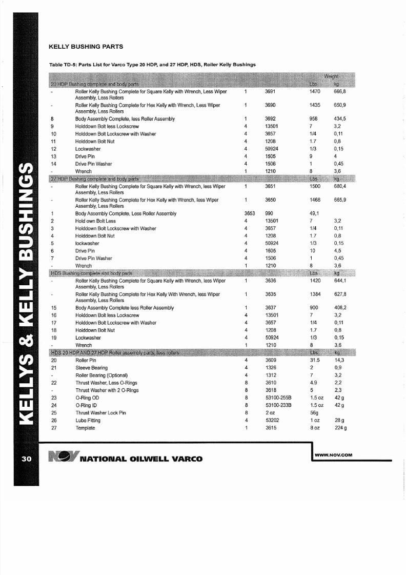
KELLY BUSHING PARTS
Table TO-5: Parts List for Varco Type 20 HOP and
7
HOP HOS Roller Kelly Bushings
Roller Kelly Bushing Complete for Square Kelly with Wrench,
Less Wiper
3691
1470
666,8
Assembly,
Less Rollers
Roller Kelly Bushing Complete for Hex Kelly with Wrench, Less Wiper 3690
1435
650,9
Assembly, Less Rollers
8
Body
Assembly
Complete, less
Roller Assembly
3692
958
434,5
9 Holddown
Bolt less
Lockscrew
4
13501
7
3,2
10 Holddown
Bolt
Lockscrew with
Washer
4
3657 1 4
0 11
11
Holddown Bolt Nut
4
1208
1.7 0,8
12
Lockwasher
4
50924 1 3
0,15
13
Drive
Pin 4
1505
9
4
14
Drive Pin Washer
4
1506
1
0,45
Wrench
1
1210
8
3,6
Roller Kelly Bushing Complete
for
Square Kelly with Wrench, less Wiper 3651
1500
680,4
Assembly, Less Rollers
Roller Kelly Bushing Complete for Hex Kelly with Wrench, less Wiper 3650
1468
665,9
Assembly, Less Rollers
1
Body Assembly
Complete,
Less Roller Assembly
3653
990
49,1
2
Hold own Bolt
Less
4
13501
7
3,2
3
Holddown
Bolt
Lockscrew
with Washer
4
3657
1 4 0 11
4
Holddown Bolt
Nut
4
1208
1.7
0,8
5
lockwasher
4
50924 1 3
0,15
6 Drive
Pin 4
1605
10 4,5
7
Drive
Pin Washer
4
1506
0,45
Wrench 1210
8
3,6
Roller
Kelly Bushing Complete
for
Square Kelly with
Wrench, less
Wiper
3636
1420 644,1
Assembly, Less
Rollers
Roller Kelly Bushing Complete
for
Hex Kelly With Wrench, less Wiper 3635
1384
627,8
Assembly,
Less Rollers
15
Body
Assembly
Complete less
Roller Assembly
3637 900
408,2
16 Holddown
Bolt less Lockscrew
4
13501
7
3,2
17
Holddown Bolt
Lockscrew with
Washer
4
3657
1 4
0 11
18 Holddown
Bolt Nut
4
1208
1.7 0,8
19 Lockwasher
4
50924
1 3
0,15
Wrench
1210
8
3,6
20
Roller Pin
4
3609
31.5
14,3
21 Sleeve Bearing
4
1326
2 0,9
Roller
Bearing
Optional)
4
1312
7
3,2
22
Thrust Washer, Less O-Rings
8
3610 4.9
2,2
Thrust Washer with 2 O-Rings
8
3618
5
2,3
23
O-Ring OD
8
53100-255B 1.50z 42g
24
O-Ring ID 8
53100-233B 1.50z
42g
25
Thrust Washer Lock Pin
8 2
oz
56g
26
Lube Fitting
4
53202
1 z 28g
27
Template
1
3615
8 z
224g
NATIONAL OILWELL
VARCO
WWW NOV COM
7/25/2019 Rotary Care & Maintenance Handbook
http://slidepdf.com/reader/full/rotary-care-maintenance-handbook 33/116
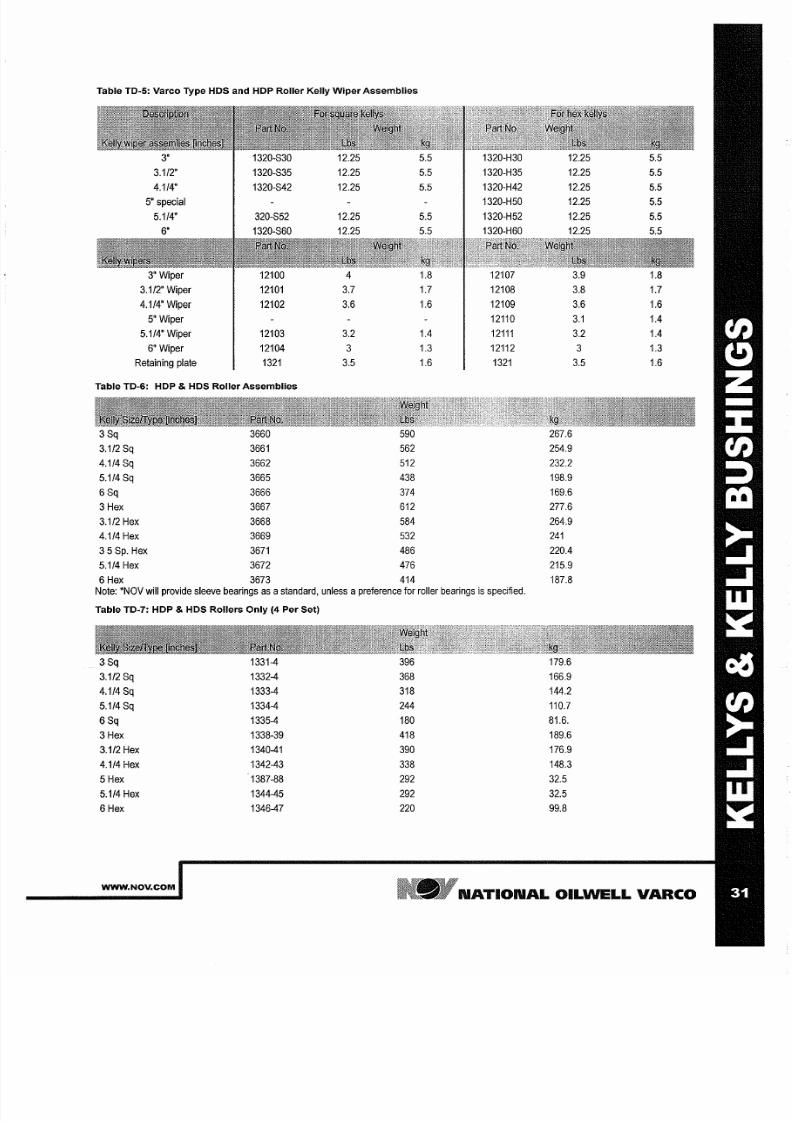
Table TO-5: Varco Type HOS and HOP Roller Kelly Wiper Assemblies
3'
1320-S30
12.25 5.5
1320-H30
12.25
5.5
3.1/2'
1320-S35 12.25
5.5
1320-H35 12.25
5.5
4.1/4'
1320-S42 12.25
5.5
1320-H42
12.25
5.5
5
special
1320-H50 12.25
5.5
5.1/4
320-S52 12.25 5.5
1320-H52
12.25
5.5
6
1320-S60 12.25
5.5 1320-H60 12.25
5.5
3
Wiper
12100
4 1.8
12107
3.9 1.8
3.1/2 Wiper 12101 3.7
1.7 12108
3.8 1.7
4.1/4'
Wiper
12102
3.6 1.6
12109
3.6 1.6
5
Wiper
12110 3 1
1.4
5.1/4
Wiper 12103
3.2 1.4 12111 3.2 1.4
6
Wiper 12104
1 3 12112
1.3
Retaining plate 1321
3.5 1.6 1321 3.5 1.6
Table TO-6: HOP HOS Roller Assemblies
3Sq 3660 590
267.6
3.1/2Sq 3661 562
254.9
4.1/4Sq 3662 512 232.2
5.1/4Sq
3665
438
198.9
6Sq 3666
374 169.6
Hex 3667
612
277.6
3.1/2
Hex
3668
584 264.9
4 114 Hex
3669
532 241
5
Sp.
Hex 3671
486 220.4
5.1/4
Hex
3672
476
215.9
6Hex
3673
414
187.8
Note: *NOV will provide sleeve bearings
as a
standard, unless
a
preference
for roller bearings
is
specified.
Table TO-7: HOP HOS Rollers Only (4 Per Set)
3Sq 1331-4
396
179.6
3.1/2 Sq
1332-4 368 166.9
4.1/4
Sq
1333-4
318
144.2
5.1/4Sq 1334-4
244 110.7
6Sq
1335-4
180
81.6.
Hex
1338-39 418 189.6
3.1/2
Hex
1340-41 390
176.9
4.1/4 Hex 1342-43 338
148.3
5
Hex
1387-88
292
32.5
5.1/4 Hex 1344-45
292 32.5
6Hex
1346-47
220
99.8
WWW NOV COM
NATIONAL OILWELL VARCO

7/25/2019 Rotary Care & Maintenance Handbook
http://slidepdf.com/reader/full/rotary-care-maintenance-handbook 34/116
N TION L
OILWELL
V RCO
WWW NOV COM
7/25/2019 Rotary Care & Maintenance Handbook
http://slidepdf.com/reader/full/rotary-care-maintenance-handbook 35/116
M STER BUSHINGS
WWW NOV COM
NATIONAL OILWELL VARCO

7/25/2019 Rotary Care & Maintenance Handbook
http://slidepdf.com/reader/full/rotary-care-maintenance-handbook 36/116
N TION L OILWELL V RCO
WWW NOV COM
7/25/2019 Rotary Care & Maintenance Handbook
http://slidepdf.com/reader/full/rotary-care-maintenance-handbook 37/116
MASTER
USHINGS
Proper handling
of
master bushings and
slips
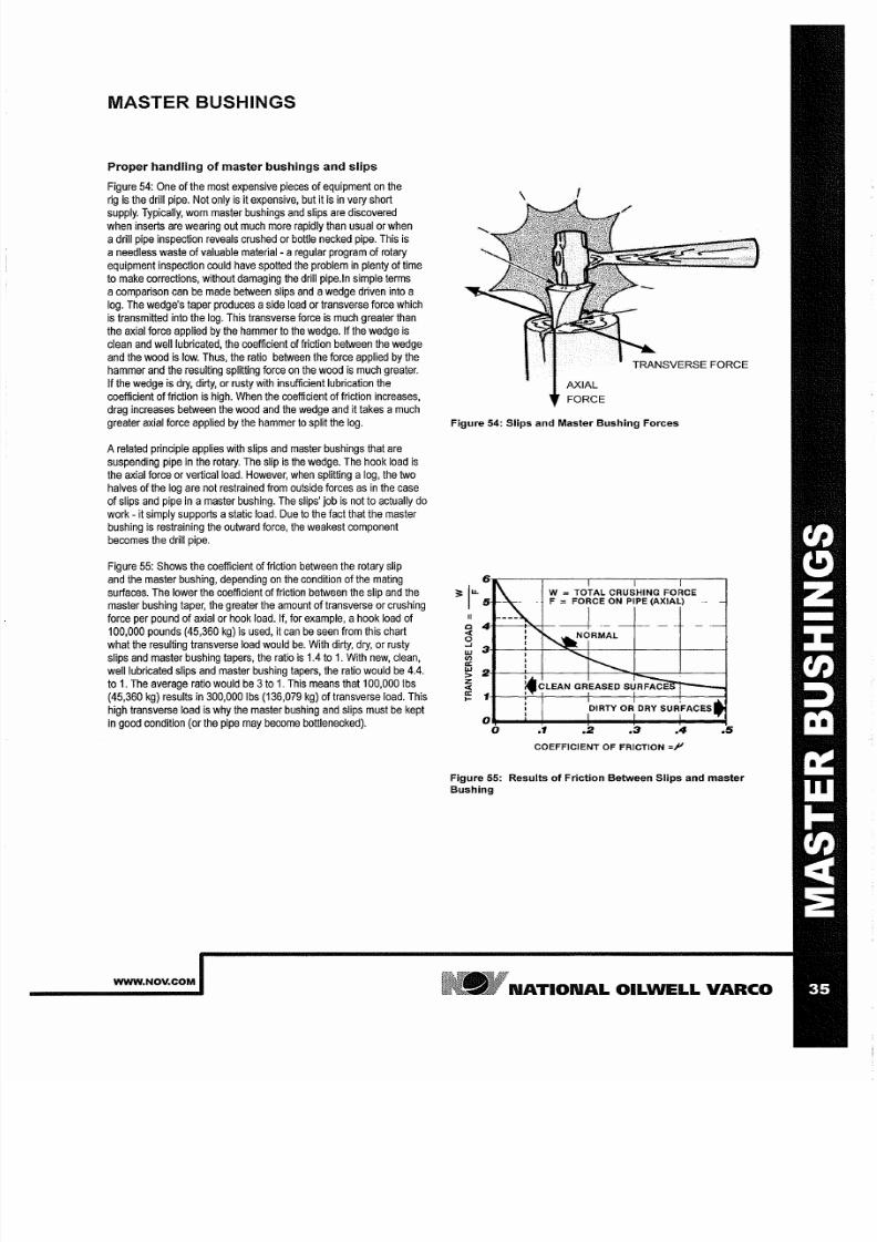
Figure
54:
One
of the
most expensive pieces
of equipment
on
the
rig is
the drill pipe. Not only
is
it expensive, but it is in
very
short
supply.
Typically,
worn master bushings and
slips
are
discovered
when inserts are
wearing
out much more
rapidly
than usual or when
adrill pipe inspection reveals crushed or bottle necked pipe. This
is
a
needless waste
of valuable material- a
regular
program of rotary
equipment inspection could
have spotted
the
problem in
plenty of
time
to make corrections, without damaging the drill pipe.ln simple terms
a
comparison
can be made between slips and awedge driven into a
log. The
wedge s
taper produces aside load
or transverse force
which
is
transmitted into the log. This
transverse force is
much greater than
the axial force
applied
by the hammer to the wedge. If the wedge
is
clean
and well
lubricated,
the
coefficient of friction
between
the
wedge
and the wood
is
low.
Thus,
the ratio between the force
applied by the
hammer
and the resulting splitting force on the wood
is
much greater.
If
the wedge
is
dry,
dirty,
or rusty
with
insufficient lubrication
the
coefficient
of
friction
is
high. When the coefficient
of
friction increases,
drag increases between the wood and the wedge
and
it takes amuch
greater
axial force
applied by the hammer to split the log.
A related principle applies with slips and master bushings that are
suspending pipe in
the
rotary. The slip is the wedge. The
hook
load
is
the
axial force or vertical
load.
However,
when
splitting a
og, the
two
halves of the log are not restrained from outside forces
as
in the case
of slips and pipe in a master bushing. The
slips job
is
not
to
actually
do
work - it simply supports astatic
load.
Due
to
the fact that
the master
bushing is
restraining
the outward force, the
weakest component
becomes the
drill pipe.
Figure 55: Shows the coefficient of
friction
between the rotary slip
and the
master
bushing, depending on the condition of the mating
surfaces.
The lower the coefficient of friction between
the slip
and
the
master bushing taper, the greater the amount of transverse or crushing
force per pound
of axial
or hook load.
If,
for
example, a
hook
load of
100,000 pounds (45,360 kg)
is
used, it can
be
seen from this chart
what the
resulting transverse
load would be With dirty, dry, or rusty
slips
and
master
bushing tapers,
the
ratio is
1.4
to 1.
With
new, clean,
well lubricated slips
and
master bushing tapers, the ratio would be
4.4.
to
1.
The
average
ratio would be 3 o 1 This means
that
100,000 Ibs
(45,360 kg) results in 300,000 Ibs (136,079 kg) of
transverse load.
This
high
transverse
load is
why the
master
bushing
and
slips must be
kept
in good condition (or the pipe may become bottlenecked).
WWW NOV COM
AXIAL
FORCE
TRANSVERSE FORCE
Figure 54: Slips and Master Bushing Forces
c
4
<I:
0
3
C/)
a
w
2
Z
<I:
a
1
0
w
=
TOTAL CRUSHING FORCE
F = FORCE ON PIPE AXIAL)
~ l
0
1
2
4
COEFFICIENT OF FRICTION
=1
5
Figure 55: Results
of
Friction Between
lips
and master
Bushing
N TION L OILWELL V RCO
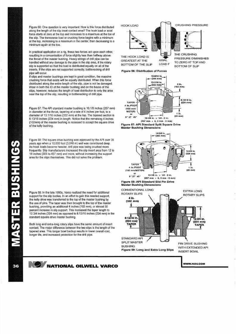
7/25/2019 Rotary Care & Maintenance Handbook
http://slidepdf.com/reader/full/rotary-care-maintenance-handbook 38/116
Figure 56: One
question is very important:
How is this
force
distributed
along .the length of the slip inset contact area? The hook load or axial
force
starts
at zero at the top and increases to a maximum at the toe
of
the slip. The
transverse
load
or
crushing force begins with a minimum
at
the
top, increasing
to
amaximum
in
the center,
then decreasing
to a
minimum again at the toe.
In
practical application
on
a
rig,
these
two
forces act
upon
each
other,
resulting
in aconcentration of
force
slightly
less
than
halfway
above
the throat of the master bushing. Heavy strings of drill pipe
can
be
handled without
any
damage to the
pipe
in
the slip
area,
if the rotary
slip is supported
so that the
load
is distributed equally on all
of the
inserts.
If
the slips are not supported correctly, botllenecking of drill
pipe
will occur.
If slips and master
bushings are
kept
in
good
condition, the massive
crushing force that
exists
will be equally distributed.
When
this
force
distributed
along the entire length of the slip, pipe is not be damaged.
Wear in both
the
ID
of
the master bushing and on
the
backs
of
the
slips, however, reduces the length
of load
distribution
to
only the area
near the top of the slip, resulting in
botllenecking
of drill pipe.
Figure 57: The API standard
master bushing is 10 118
inches 257 mm)
in diameter at the throat,
tapering
at a
rate
of 4 nches
per foot, to
a
diameter of 13 1/16 inches
332
mm) at the top. The tapered
section
is
8 13/16
inches
224 mm) in length. Notice
that
the remaining 4 nches
1
02mm)
of the
master bushing is recessed
to
accept the square
drive
of the kelly bushing.
Figure
58: The square drive bushing was approved by
the
API over
35
years
ago when a 10,000
foot
3,048 m) well was considered
deep.
As hook loads became heavier, drill pipe was being crushed more
frequently.
Slip manufacturers
increased
the
slip
insert
area
from
12
to
18
inches 305
to
457
mm) and more,
without
increasing the
support
area for the slips themselves. This did not solve the problem.
Figure 59:
In
the
late
1950s,
Varco
realized the need for
additional
support
for the slip
bodies. In an effort
to
gain
this
needed support,
the kelly drive was transferred to the top of the master bushing by
the use of pins. The
taper
was then brought to the top of the master
bushing, providing
an
additional
4
nches 102
mm),
or
almost
50
percent
increase
in
slip
support. This increased
the taper
length
to
12 3/4
inches
324 mm)
as
opposed to
8 13/16 inches
224 mm) in the
standard
square drive
master bushing.
Both long and extra-long rotary slips have the same amount
of
insert
contact. The major
difference
between the two
slips
is
the
length of
the
tapered
area. This
longer bowl
backup results in lower
overall
cost,
longer life,
and
increased protection for the drill pipe.
N TION L OILWELL V RCO
HOOK LOAD
THE
HOOK LOAD IS
GREATEST AT
THE
BOTTOM OF
THE
SLIP
LO DF
Figure 6: Distribution of Forces
or
9
27'
45'
in. +
1 4 ·0
in.
257
mm
+ 6, 3
mm
. 0
mm
CRUSHING PRESSURE
PRESSURE DIMINISHES
TO ZERO AT TOP
ND
BOTTOM OF SLIP
Figure 7: API Standard Split Square Drive
Master Bushing Dimensions
r
9° 27' 45'
1 ) 1/8
in.
+
1 4 ·0 in.
257 + 6, 3 mm
.
0 mm
Figure 8: API Standard Slid Pin Drive
Master Bushing Dimensions
CONVENTIONAL LONG
ROTARY SLIPS
SPLIT MASTER
BUSHING
Figure 9: Long and Extra Long Slips
EXTRA LONG
ROTARY SLIPS
PIN DRIVE BUSHING
WITH EXTENDED API
INSERT BOWL
WWW NOV COM
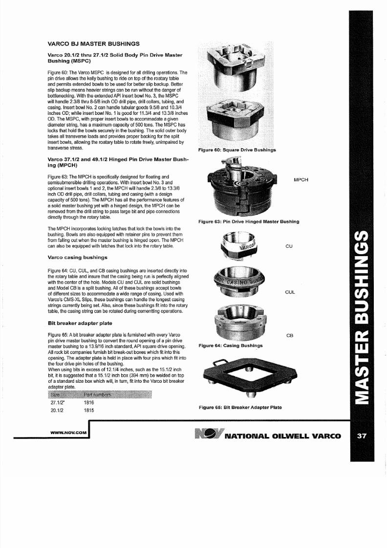
7/25/2019 Rotary Care & Maintenance Handbook
http://slidepdf.com/reader/full/rotary-care-maintenance-handbook 39/116
VARCO J MASTER BUSHINGS
Varco 20 1/2 thru 27 1/2 Solid Body Pin Drive Master
Bushing MSPC)
Figure
60:
The Varco
MSPC
is designed for all drilling
operations.
The
pin
drive
allows the kelly bushing to ride
on
top
of
the roatary table
and
permits extended bowls to
be
used
for better slip
backup.
Better
slip
backup means
heavier strings can
be run
without the danger
of
bottlenecking. With the extended
API
insert bowl No.3, the MSPC
will handle
2.3/8
thru 8-5/8 inch OD drill pipe, drill collars, tubing, and
casing. Insert bowl No.2
can
handle tubular
goods 9.5/8
and
10.3/4
inches
OD;
while insert bowl
No.
s good for 11.3/4
and
13.3/8 inches
OD. The MSPC,
with proper
insert bowls to accommadate agiven
diameter
string,
has amaximum
capacity
of
500
tons. The MSPC has
locks that hold the bowls securely in the
bushing. The
solid outer body
takes all transverse loads
and
provides proper backing for the
split
insert bowls, allowing the roatary
table
to rotate
freely,
unimpaired by
transverse stress.
Varco 37 1/2 and 49 1/2 Hinged Pin Drive Master Bush-
ing MPCH)
Figure
63: The MPCH is specifically designed
for
floating and
semisubmersible drilling
operations.
With
insert bowl No.3 and
optional insert bowls and 2, the
MPCH
will
handle
2.3/8
to
13.3/8
inch OD drill pipe, drill
collars,
tubing and casing (with adesign
capacity
of 500 tons). The MPCH has all
the performance features of
asolid master bushing
yet
with a
hinged
design, the
MPCH can
be
removed from the drill string to pass large bit and pipe
connections
directly
through the rotary
table.
The MPCH incorporates locking
latches
that
lock
the bowls into the
bushing.
Bowls are also equipped with
retainer pins
to
prevent them
from falling out when the master bushing
is
hinged open. The
MPCH
can
also be equipped with
latches that lock
into the rotary table.
Varco casing bushings
Figure
64: CU
CUL,
and CB casing
bushings
are
inserted
directly into
the
rotary
table
and insure that
the casing being
run
is perfectly
aligned
with the center of the
hole.
Models CU
and
CUL are solid bushings
and Model CB
is
asplit bushing. All of these bushings
accept
bowls
of different
sizes to accommodate
a
wide
range of
casing. Used
with
Varco's CMS-XL Slips, these bushings can handle the longest casing
strings
currently being set. Also, since these
bushings
fit into the rotary
table, the casing string
can
be rotated
during cementting
operations.
Bit breaker adapter plate
Figure
65:
A
bit
breaker adapter
plate
is
furnished
with every
Varco
pin drive master bushing to
convert
the round opening of apin drive
master
bushing to a
13.9/16 inch standard,
API square
drive opening.
All rock bit companies furnish bit break-out boxes which
it
into
this
opening. The adapter plate
is
held in
place with
four pins which fit into
the
four drive
pin
holes
of the bushing.
When
using
bits
in excess
of
12.1/4 inches, such
as
the 15.1/2 inch
bit,
itis suggested that a15.1/2 inch box (394
mm)
be welded on top
of
a
standard
size box which
will,
in turn, fit
into
the Varco bit
breaker
adapter plate.
27.1/2 1816
20.1/2
1815
WWW NOV COM
Figure 60: Square Drive Bushings
MPCH
Figure 63: Pin Drive Hinged Master Bushing
CU
CUL
CB
Figure 64: Casing Bushings
Figure 65: Bit Breaker Adapter Plate
N TION L OILWELL V RCO

7/25/2019 Rotary Care & Maintenance Handbook
http://slidepdf.com/reader/full/rotary-care-maintenance-handbook 40/116
M INTEN NCE ND INSPECTION
Maintenance
Figure
66:
1
When
changing
insert
bowls, check top
diameter
of bushing
bore and inspect bowl seat for burrs and peened-over edges;
file
or grind
flush
as required. This
procedure
will ensure easy
installation
and
proper fit.
2. Clean the
inside
taper of
the
drilling bowls of any
abrasive
material. This
will cut
down the rapid wear on both
slip
backs
and
taper. It will
also provide
easy handling of slips and
keep
them
from sticking in the bushing.
3 Lubricate the inside taper of the drilling bowls when tripping) to
prevent slips
from
sticking in
the bowls.
4. Lubricate the back of the drilling bowl each time it
is
removed
from the hull. This will prevent the
bowls
and
slips
from
sticking
and reduce master bushing
10
wear.
5
Replace
lock assembly
when
it
ceases
to function.
Figure 89:
6
Replace the API drilling
bowls
when throat measurement exceeds
10 718 inches 276 mm)
on
extended
API
bowls.
7.
Replace
API
drilling
bowls when
a
straight
edge
held
against
taper indicates
wear
from the tool joint in
the tapered section of
the bowls
8 When the backs of the rotary slips and the taper of the bowls
become rough, both of these surfaces
must
be polished by using
emery
cloth on the backs
of
the slips or
a lexible, fine
sandpaper
disk. Keeping these surfaces polished will help prevent sticking.
9
Hinge Pins MPCH Only):
The
stationary
hinge
pin
without bail)
has one
lube fitting located
at top
center.
This pin
should be
greased daily.
The removable hinge pin with
bail)
should be
cleaned
up and
greased
each
time it
is taken out.
It has a ube
fitting
located
at
top
center.
Inspection
Figure
66:
Inspection
is
the most important aspect of preventive
maintenance. Inspection consists of observing, measuring, and testing.
There
is
wear in the
10
of the rotary table which gives
insufficient
support
for
the master bushing itself.
1.
The of the master
bushing
is
worn.
2 There
is
excessive wear in
the
taper
and
the throat 10
Figure
67: These
wear conditions
affect
the function of
the
slips
themselves:
1. The reduced backup area
for
the
slip
causes
wear and crushing
in the
backs of
the
slips.
2.
The
gripping
area
of
the
slips
on
the
pipe is
greatly
reduced.
3 Slips used under these conditions are
easily
deformed. Drill pipe
darnage
is
likely
to
occur.
Observing
the
height
of
set
slips in the
master
bushing
is
an
easy means of checking for
wear.
The slips
ride high in the master bushing when the rotary equipment
is
in
good
condition.
Figure
68:
4 As the system wears, slips ride lower in the rnaster bushing.
N TION L OILWELL V RCO
GRIPPING
AREA
OF SLIPS
WO
AREA
CAUSES
WEAR
AND CRUSHING IN
BACKS OF SLIPS
PIPE IS
BOTILENECKED
IN BOWL
CONDITIONS ARE
READILY DEFORMED
Figure 66: Rotary Equipment Wear Points
WWW NOV COM

7/25/2019 Rotary Care & Maintenance Handbook
http://slidepdf.com/reader/full/rotary-care-maintenance-handbook 41/116
PAPER TEST: TESTING OF ROTARY EQUIPMENT
WEAR
paper test according
to
TSEL-0158
s
the best
way to
determine the
deg ree
of
rotary equipment wear. This test
should
be performed every
three months and
each
time a
new
master bushing or
slip
set s put into
service.
For
accurate results,
RULE OF
THUMB:
use ahook
load of at
least 10,000 Ibs 4,535 kg) per column.
General procedure
Clean an area
of
pipe
where
there
are no
insert marks. Clean slip
inserts
with awire brush.
Figure
69:
Wrap
a
ayer of test paper around
the cleaned section
of
pipe.
Varco can supply test paper or a ayer
of
mud sack paper will serve the
purpose. Use friction tape to hold the
paper
to the pipe.
Figure
70:
Place the
slips
around
the
pipe and hold them while the pipe
is lowered at normal speed.
Figure
71:
After
the slips
have
been
set,
hold
them firmly around the
pipe
as
it is raised. they should be removed carefully to prevent damage
to the paper. Evaluation should be done
using
the second layer
of
the
paper
because
the
outside
layer will have
misleading
slip
impressions.
Use TSEL-0158 Paper Test for
logging
the
results
of the
Paper
Test.
Recognizing worn equipment and how to solve the
problem
Figure
74:
This is
a
worn
split master
bushing
in a rotary. The space
at
the
top,
approximately 1 4 inch
6,5-mm)
between
these two
bushing
halves.
The space at the bottom however,
has
increased
to more than
3 4 inch 19 mm). This reduces
support for
the
slips
and
causes
drill pipe
damage. The
white line see arrow) indicates where the throat of the
master bushing
was when
new.
WWW NOV COM
Figure 69: Wrapping Test Paper Around Kelly
Figure 71: Removing Slips
Figure 74: Master Bushing Wear
N TION L OILWELL V RCO
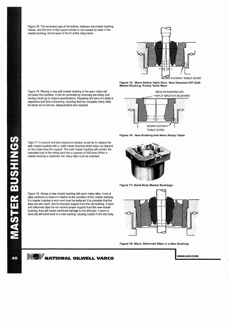
7/25/2019 Rotary Care & Maintenance Handbook
http://slidepdf.com/reader/full/rotary-care-maintenance-handbook 42/116
Figure
75: The increased gap
at
the bottom, between
the master
bushing
halves, and
the
lack of
slip support shown is not caused by
wear
in the
master bushing, but
by
wear in the
I of
the rotary table.
Figure 76: Placing
anew
split master bushing in the worn
rotary
will
not
solve
this problem. It can be corrected by removing the
rotary
and
having
it built
up
to original
specifications.
Repairing the bore
of
a
able
is
expensive and time consuming, requiring that the complete rotary table
be taken out of
service,
disassembled and repaired.
Figre
77:
second
and less
expensive solution would
be
to replace the
split master bushing with
a
solid master bushing
which
does not depend
on
the
rotary bore
for
support.
The
solid master bushing will contain the
complete
load of
the string
and
has
a
capacity of 500 tons).when
a
master bushing
is
replaced, the rotary slips must be checked.
Figure 78 Shows
a
new master
bushing
with wom rotary slips.
set
of
slips conforms or wears in relation to the condition of the master bushing.
If a
master
bushing
is
worn
and
must
be
replaced;
it
is
probable that
the
slips are also
worn,
due
to improper
support from
the old bushing. If
worn
and deformed slips do not receive proper support from the
new
master
bushing, they will cause continued damage to the drill pipe. worn or
bent slip will
bend back in anew
bushing, causing
cracks in the
slip
body.
N TION L OILWELL V RCO
Figure 75: Worn Rotary Table Bore. New Standard API Split
Master Bushing. Rotary Table Wear
N W ST ND RD API
T BLE BORE
Figure 76: New Bushing and Worn Rotary Table
Figure 77: Solid Body Master Bushings
Figure 78: Worn Deformed Slips n a New Bushing
WWW.NOV.COM
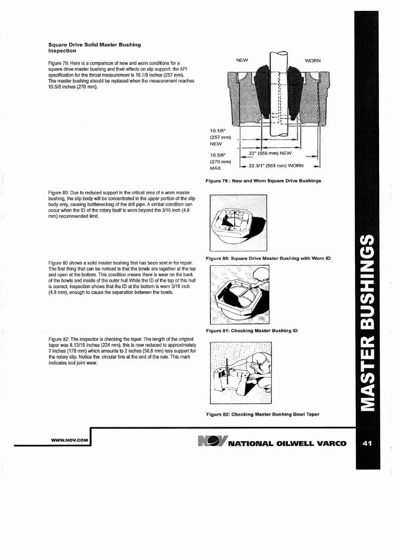
7/25/2019 Rotary Care & Maintenance Handbook
http://slidepdf.com/reader/full/rotary-care-maintenance-handbook 43/116
Square Drive Solid Master Bushing
Inspection
Figure
79: Here
is
a comparison of
new
and worn conditions for a
square drive master bushing and their effects on slip support: the API
specification for the throat measurement
is
10.1/8 inches 257 mm).
The
master
bushing
should
be replaced
when the measurement
reaches
10 5/8 inches 270
mm).
Figure
80: Due to reduced
support
in the
critical
area of aworn master
bushing,
the slip body will
be
concentrated in the upper
portion of
the slip
body
only, causing
bottlenecking
of
the drill pipe. Asimilar condition
can
occur when
the 1
of the rotary itself is worn beyond
the 3/16
inch 4.8
mm) recommended
limit.
Figure 80 shows
a
solid master
bushing that has been
sent
in
for
repair.
The
first thing
that can
be
noticed
is
that the bowls are together at the top
and
open at the bottom. This condition means there is wear on the back
of the bowls and inside of the
outer hull.While
the 1 of the top of this hull
is correct,
inspection
shows that
the 1 at the
bottom
is worn 3/16 inch
4.8 mm), enough to
cause
the
separation between the bowls.
Figure 82:
The inspector
is
checking
the taper.
The length of
the original
taper was 8 13/16 inches 224 mm). this
is
now reduced
to
approximately
7 inches 178 mm) which amounts to 2 nches 50,8
mm)
less support for
the
rotary
slip. Notice the
circular
line at the
end
of the
rule.
This
mark
indicates tool
joint wear.
WWW NOV COM
10.1/8
257mm)
N W
10.5/8
270
mm)
MAX.
NEW
WORN
22.3/1 (563
mm)
WORN
Figure 79 : New and Worn Square Drive Bushings
Figure 80: Square Drive Master Bushing with Worn ID
Figure 81: Checking Master Bushing ID
Figure 82: Checking Master Bushing Bowl Taper
N TION L
OILWELL
V RCO

7/25/2019 Rotary Care & Maintenance Handbook
http://slidepdf.com/reader/full/rotary-care-maintenance-handbook 44/116
Figure
83:
Shows
the start
of the
new
taper that
has been
cut
by
the
wear
of
tool joints which pass
through
the
rotary.
The effective backup
for the rotary slip
has
now been reduced to 5 nches 127 mm). When
using a ong rotary slip, the total length of the slip
s
20
inches 508 mm)
with
16.1/2 inches 419 mm)
of inserts. Working
n
a bushing with only
5
inches 127
mm) of
tapered area for backup will cause the backs
of
the
slips to crush.
Pin-Drive Solid Master Bushing Inspection
Figure
84: Compares
new
and wom
conditions
for apin drive
master
bushing and the
effects on slip
support. The API
specification
for
the
throat measurement is 10.1/8 inches 257
mm).
Figure
85: The maximum allowable
wear
has
increased
to 10.7/8 inch
276 mm) .
This
limit prevents damage to
drill
collar
slips
which
were
designed
for
the
shorter taper of
the square
drive master
bushing. Notice
that the toe of the
slip
has
pulled away from the drill pipe.
This
s
due
to the
combination
of
wear
n the throat
area
and the
outer
hull. If the
ID
of
the
outer
hull were
n
good
condition,
the
slips
would
still
have
good
support
and
proper contact
with
the drill pipe. Even though there
would
not
be
damage
to
drill
pipe,
deformities
n
the drill
collar would still
occur.37.1/2 Hinged
Master
Bushing.
HARD
BANDING
INCORRECT
TAPER
CUT BY
TOOL JOINT
(270
mm) WORN
Figure 83: Square Drive Bushing Worn By Tool
Joint
KS
The throat and outer hull
wear measurements
are the same as the
extended
bowl.
For
hinged
master bushings,
awear zone must
be
considered - the
hinge
pin. Maximum wear
s
.032 inch 0.8
mm).
Beyond this point, conditions similar to wear n the ID
of
the rotary on a Figure 84: New and Worn Pin Drive Bushings
split square
drive master bushing
will exist, allowing the
bushing halves
WORN
to separate
and
reduce slip back-up area. N
Use apry bar at
the
hinged
section to
move the bushing
back
and forth,
to determine wear. Maximum
movement
should not exceed 1/16 inch 12.3/4
UP
1.6 mm). (324 mm) ~ - - f j J , - ~ . , . , . J . m - - - I - I - - H : r - - 1 f i ' j j
Figure
86-1:
As With the square
drive
bushing, the obvious problem
s
that
the
bowls
are together at the
top and
open at
the
bottom.
Figure
86-2: Shows apin drive master bushing that has
been
sent
n for
repair.
WORN
HINGE PIN
(MAX. WEAR OCCURS
AT BOTTOM OF PIN)
0.032
0.81
mm)
MAX
Figure 86-2: Worn
1.0.
N TION L OILWELL V RCO
WE R
DUE TO PIPE
DRAGGING
THROUGH
BUSHING
Figure 85: Comparison of New and Worn Hinged Master
Bushing
Figure 86-1: Pin Drive Master Bushing tops together
WWW.NOV.COM
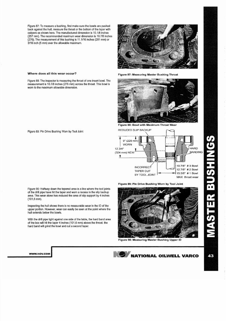
7/25/2019 Rotary Care & Maintenance Handbook
http://slidepdf.com/reader/full/rotary-care-maintenance-handbook 45/116
Figure
87:
To
measure abushing, first
make sure
the
bowls are pushed
back
against
the
hull, measure
the
throat
or
the bottom
of
the
taper
with
calipers
as
shown here. The manufactured dimension
is
10 1/8 inches
257
mm). The recommended maximum wear dimension is
10 718
inches
276).
The measurement
of
this
bushing
is
11 1/16 inches 281
mm)
or
3/16
inch 5 mm)
over the
allowable
maximum.
Where does all this
wear
occur?
Figure 88: The inspector
is
measuring the throat
of
one insert bowl. The
measurement is 10 718
inches 276 mm) across the throat. This
bowl
is
worn
to the
maximum allowable
dimension.
Figure
89:
Pin
Drive Bushing Worn
by
Tool Joint
Figure 9 : Halfway
down the tapered
area
is
a
ine where the
tool joints
of the drill pipe
have
hit the taper
and
worn a recess in the slip backup
area. This wear alone has reduced the area of slip support
by
4 nches
101,6
mm).
Inspecting
the hull shows there
is no
measurable wear in the 1 of the
upper
portion.
However,
wear can easily be seen
at the point
where
the
hull
extends below
the
bowls.
With the
drill
pipe tight
against
one side
of
the table, the
hard
band area
of the box will
hit
the
taper 4
nches 101,6 mrn)
above the
throat. the
hard band will grind the bowl and cut asecond taper.
WWW NOV COM
Figure 87: Measuring Master Bushing Throat
Figure 88: Bowl with Maximum Throat Wear
12.3/4
(324 mm)
TAPER
UT
BYTOOLJOINT l - - - ~ - 1 1 5 . 5 / 8 1
Bowl
ING
MAX throat wear
Figure 89: Pin Drive Bushing Worn
y
Tool Joint
Figure 9 : Measuring Master Bushing Upper ID
N TION L OILWELL V RCO
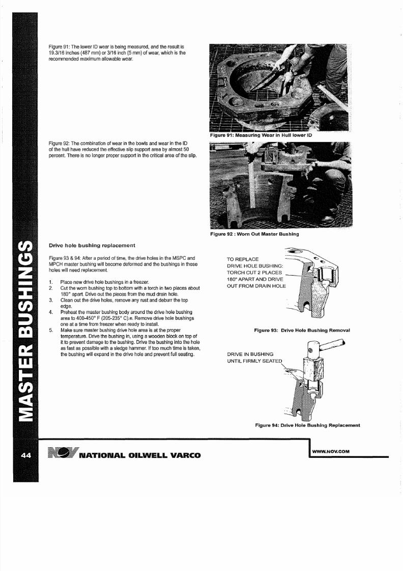
7/25/2019 Rotary Care & Maintenance Handbook
http://slidepdf.com/reader/full/rotary-care-maintenance-handbook 46/116
Figure 91:
The lower 10 wear
is being
measured,
and the
result
is
19.3/16 inches 487
mm)
or 3/16 inch 5 mm) of wear, which
is
the
recommended maximum allowable wear.
Figure 92: The combination of wear in the bowls and wear
in
the 10
of the hull
have reduced
the effective slip
support area
by
almost
50
percent. There is no longer proper support in the critical area of the slip.
Drive hole bushing replacement
Figure 93 94:
After
a
period
of time, the
drive
holes in the
MSPC
and
MPCH
master
bushing
will
become
deformed
and
the bushings
in
these
holes will
need
replacement.
1 Place new drive hole bushings in
a
reezer.
2 Cut the worn bushing top to bottom with a orch in
two
places about
180
0
apart.
Drive out the
pieces from
the mud
drain
hole.
3 Clean out the drive
holes, remove
any rust and deburr the top
edge.
4. Preheat the master bushing
body around
the
drive hole bushing
area
to 400-450
0
F
205-235
0
C).e.
Remove drive hole bushings
one
at
a ime from
freezer
when ready to
install.
5.
Make
sure master bushing drive
hole area
is
at
the
proper
temperature. Drive the
bushing in, using a
wooden block
on
top of
it
to
prevent damage
to the bushing. Drive the bushing
into
the
hole
as fast as
possible
with a
sledge
hammer. If too
much time
is
taken,
the bushing will
expand
in the drive hole and prevent full seating.
N TION L OILWELL V RCO
Figure 91: Measuring Wear in Hull lower 10
Figure 92 : Worn Out Master Bushing
TO REPLACE
DRIVE HOLE BUSHING:
TORCH CUT 2 PLACES
180
0
APART
ND
DRIVE
OUT
FROM DRAIN HOLE
Figure 93: Drive Hole Bushing Removal
DRIVE IN BUSHING
UNTIL FIRMLY
Figure 94: Drive Hole Bushing Replacement
WWW NOV COM
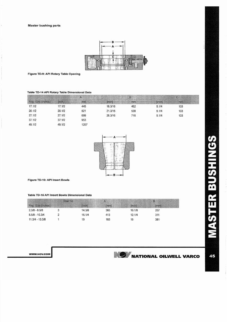
7/25/2019 Rotary Care & Maintenance Handbook
http://slidepdf.com/reader/full/rotary-care-maintenance-handbook 47/116
Master bushing parts
Figure TD 9: API Rotary Table Opening
Table TD 14 API Rotary Table Dimensional Data
17.1/2
17.1/2 445
20.1/2 20.1/2 52
27.1/2
27.1/2
699
37.1/2
37.1/2
953
49.1/2
49.1/2 257
Figure TD 10: API Insert Bowls
Table TD 15 API Insert Bowls Dimensional Data
2.3/8 8.5/8
8.5/8 10.3/4
11 314 13.3/8
WWW NOV COM
3
14.3/8
16.1/4
9
18.3/16
21.3/16
28.3/16
365
4 3
83
462
538
7 6
10.1/8
12.1/4
5
5 114
5 114
5 114
257
3
38
33
33
33
N TION L OILWELL
V RCO
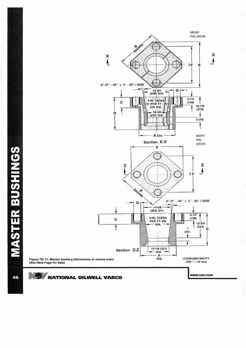
7/25/2019 Rotary Care & Maintenance Handbook
http://slidepdf.com/reader/full/rotary-care-maintenance-handbook 48/116
x
t
Figure TD-11: Master bushing Dimensions
in
inches mm)
See Next Page or data)
c
f
N TION L OILWELL V RCO
Section X X
E
DIA
MDSP
PIN DRIVE
1
tF
I
PIN
DRIVE
z
j
tCONCENTRICITY
.030 -.76
mm
x
J
WWW NOV COM
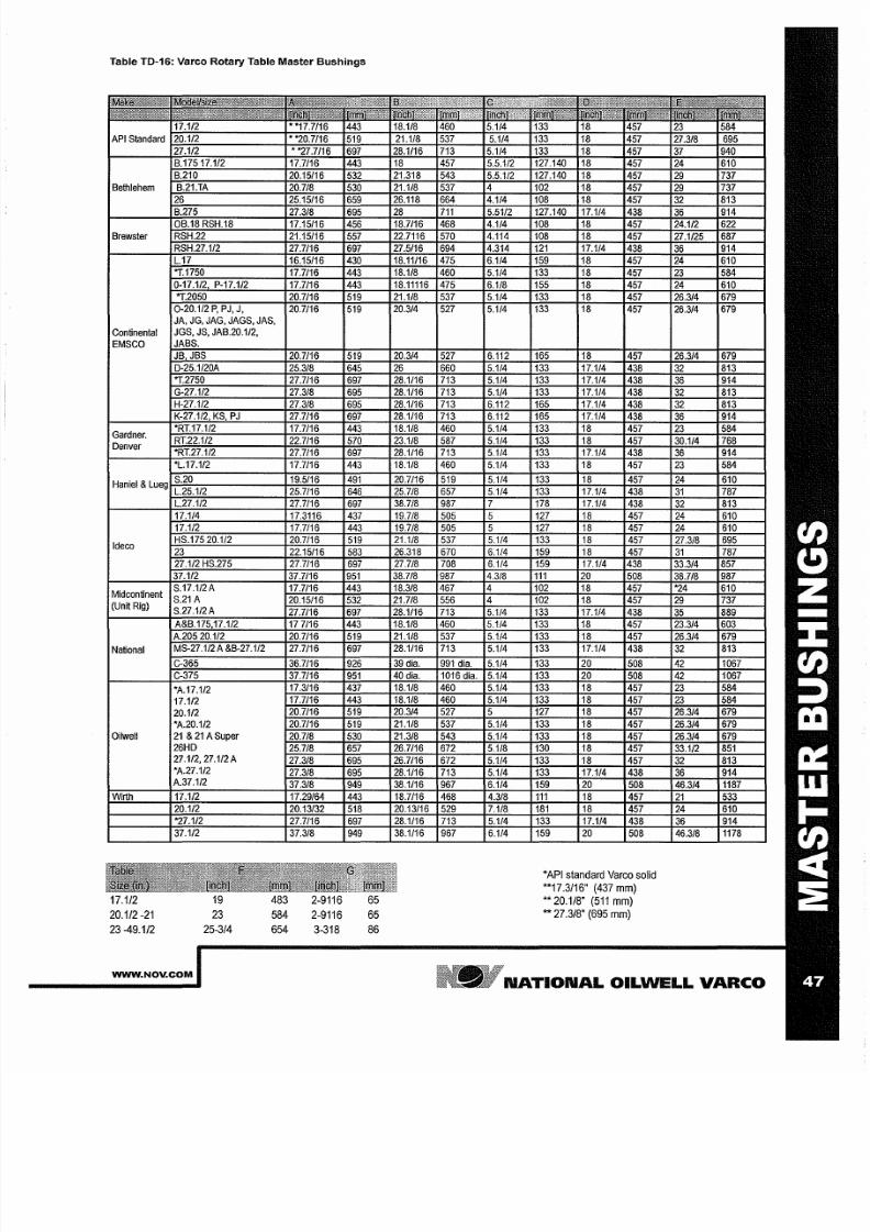
7/25/2019 Rotary Care & Maintenance Handbook
http://slidepdf.com/reader/full/rotary-care-maintenance-handbook 49/116
Table TD 16: Varco Rotary Table Master Bushings
Bethlehem
Brewster
Continental
EMSCO
Gardner.
Denver
Ideco
Midcontinent
(Unit Rig)
National
A.17.1/2
17.1/2
20.1/2
A.20.1/2
Oilwell
21 21
A
Super
26HD
27.1/2,27.1/2A
A.27.1/2
17.1/2
20.1/2 -21
23
-49.1/2
WWW NOV COM
1/2
19
23
25-3/4
483 2-9116
584 2-9116
654 3-318
65
65
86
*API standard Varco solid
**17.3/16
(437
mm)
**
20.1/8
511 mm)
** 27.3/8
(695 mm)
N TION L
OILWELL
V RCO
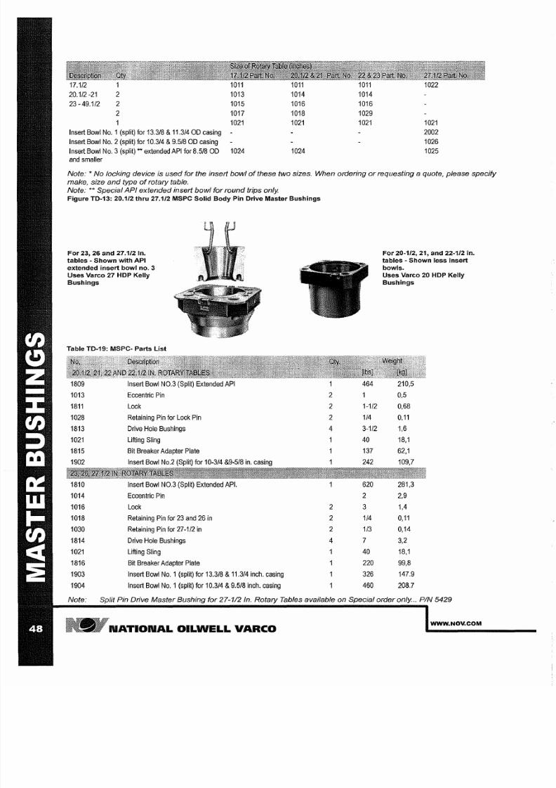
7/25/2019 Rotary Care & Maintenance Handbook
http://slidepdf.com/reader/full/rotary-care-maintenance-handbook 50/116
17.1/2 1011
20.1/2 21 2 1013
23 -49.1/2
2 1015
2 1017
1021
Insert Bowl No.1 (split) for 13.3/8 11.3/4
OD
casing
Insert Bowl No.2 (split) for 10.314 9.518 OD casing
Insert Bowl No.3 (split)
**
extended API for 8.5/8 OD 1024
and
smaller
1011
1014
1016
1018
1021
1024
1011
1014
1016
1029
1021
1022
1021
2002
1026
1025
Note:
*
No locking device is used for the insert bowl of these two sizes. When ordering or requesting a quote please specify
make size nd type
of
rotary table.
Note: ** Special API extended insert bowl for round trips only.
Figure TD-13: 20.1/2 thru 27.1/2 MSPC Solid Body Pin Drive Master Bushings
For
23 26 and 27.1/2 In.
tables - Shown with API
extended insert bowl no. 3
Uses Vareo 27 HDP Kelly
Bushings
Table TD-19: MSPC- Parts List
1809
Insert Bowl NO.3 (Split) Extended API
1013
Eccentric
Pin
1811
Lock
1028
Retaining
Pin
for
Lock Pin
1813
Drive
Hole
Bushings
1021
Lifting Sling
1815
Bit Breaker Adapter Plate
1902
Insert Bowl
No.2 (Split) for
10-3/4
9-5/8 in. casing
1810
Insert
Bowl
NO.3
(Split)
Extended
API.
1014
Eccentric
Pin
1016
Lock
1018
Retaining Pin for 23 and
26 in
1030
Retaining Pin for
27 1/2
in
1814 Drive Hole Bushings
1021 Lifting Sling
1816 Bit
Breaker Adapter
Plate
1903 Insert
Bowl
No.1 (split)
for
13.318 11.3/4 inch. casing
1904
Insert
Bowl No.1
(split)
for
10.314 9.5/8 inch. caSing
2
2
2
4
2
2
2
4
464
1 1/2
1/4
3 1/2
40
137
242
620
2
3
1/4
1/3
7
40
220
326
460
For 20-1/2 21 and 22-1/2 in.
tables - Shown less insert
bowls.
Uses Va reo 20 HDP Kelly
Bushings
210,5
0,5
0,68
0 11
1,6
18,1
62,1
109,7
281,3
2,9
1,4
0 11
0,14
3,2
18,1
99,8
147.9
208.7
Note:
Split Pin Drive Master Bushing for 27 112 In. Rotary Tables available on Special order only. .. PIN 5429
N TION L OILWELL V RCO
WWW NOV COM
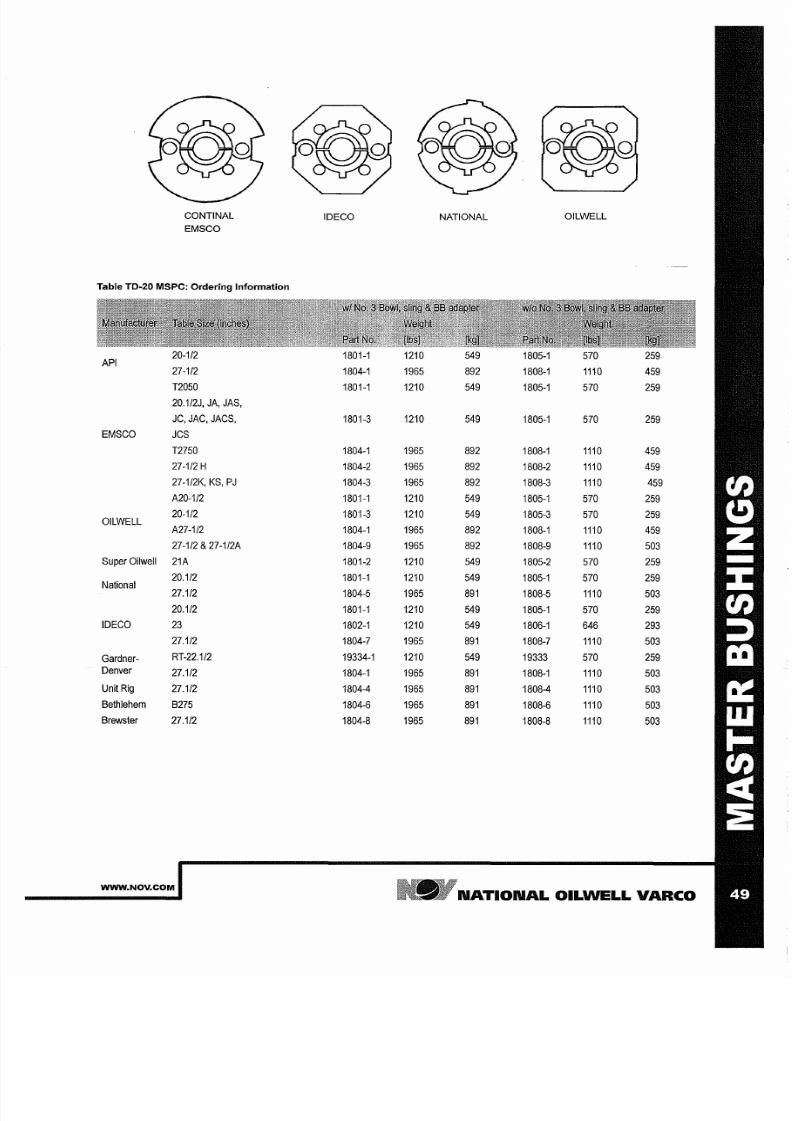
7/25/2019 Rotary Care & Maintenance Handbook
http://slidepdf.com/reader/full/rotary-care-maintenance-handbook 51/116
CONTINAL
EMSCO
Table TD-20 MSPC: Ordering nformation
API
20-1/2
27-1/2
T2050
20.1/2J
JA JAS
JC JAC JACS
EMSCO
JCS
T2750
27-1/2H
27-1 12K KS PJ
A20-1/2
OILWELL
20-1/2
A27-1/2
27-1/2 27-1/2A
Super
Oilwell
21A
National
20.1/2
27.1/2
20.1/2
IDECO
23
27.1/2
Gardner-
RT-22.1/2
Denver
27.1/2
Unit
Rig
27.1/2
Bethlehem B275
Brewster 27.1/2
WWW NOV COM
IDECO
1801-1
1804-1
1801-1
1801-3
1804-1
1804-2
1804-3
1801-1
1801-3
1804-1
1804-9
1801-2
1801-1
1804-5
1801-1
1802-1
1804-7
19334-1
1804-1
1804-4
1804-6
1804-8
NATIONAL
OILWELL
1210 549
1805-1
570 259
1965
892
1808-1
1110 459
1210
549
1805-1 570 259
1210
549
1805-1
570 259
1965 892
1808-1 1110
459
1965 892
1808-2
1110
459
1965
892
1808-3 1110
459
1210 549 1805-1
570 259
1210 549 1805-3 570
259
1965
892
1808-1 1110 459
1965 892 1808-9
1110 503
1210 549
1805-2
570 259
1210
549
1805-1
570 259
1965
89
1808-5
1110
503
1210
549
1805-1 570
259
1210
549
1806-1 646
293
1965
89
1808-7
1110 503
1210
549
19333 570
259
1965
89
1808-1 1110 503
1965
89
1808-4
1110
503
1965
891
1808-6 1110
503
1965 891 1808-8 1110
503
N TION L
OILWELL V RCO

7/25/2019 Rotary Care & Maintenance Handbook
http://slidepdf.com/reader/full/rotary-care-maintenance-handbook 52/116
MPCH Master bushings
Figure TD-14: MPCH Hinged Pin Drive Master Bushing
Table TD-21: MPCH Parts List
6608
Insert
Bowl NO.3
Split)
Extended API. 625
283.5
6604
Hinge Pin, removable
80
36.3
6605 Hinge Pin, stationary wllube fitting
75
34
6606
Hinge Pin Retainer. 3oz.
0.06
1014
Eccentric
Pin
0.9
50106-22 Eccentric
Pin
Retainer.
20z.
0.06
1016
Lock 3
1.4
3699
Drive Hole Bushing
w
locking pocket.
4 7
3.2
6699
Lifting Sling
150
68
1816
Bit
Breaker Adapter
Plate
220
99.8
6610 Insert
Bowl
No 1 Split) for 13 3/8
and
11 3/4
casing
336 152.4
6609
Insert Bowl No.2 Split) for 10 314
and 9.518
casing
470
213.2
Note: When ordering
or
requesting a quote please specify size make and model
o
rotary table.
Table TD-22: MPCH-Ordering Information
37 1/2
SIN
6600-2A 4325 1961,8 6601-2A 3325 1508.2
EMSCO
1-48)
6600-2 4149
1882
6601-2 3149
1428.4
37 1/2
SIN 49
up) to
49 1/2
Oilwell
37 1/2
to
49 1/2
6600-3 4245
1925,5 6601-3 3245
1471.9
IDECO
37 1/2
6600-4
4015 1821.2
6601-4
3015
1637.6
36 1/2
6600-5 3910 2095.8 6601-5 2905
1317.7
National
37 1/2 to 49 1/2
6600-1 4029 1827.5 6601-1
3029 1373.9
Wirth 37 1/2
to
49 1/2 6600-3
4245 1925.5 6601-3
3245
1471.9
N TION L OILWELL V RCO
WWW NOV COM

7/25/2019 Rotary Care & Maintenance Handbook
http://slidepdf.com/reader/full/rotary-care-maintenance-handbook 53/116
I
z
o no
2
~
-
2 ~ c
i
I
~ :
a
8
R
o
t
a
r
y
T
T
e
S
z
O
D
D
A
M
S
P
T
B
N
T
3
1
C
[
J
S
~
3
1
·
1
M
_
H
N
P
N
D
V
2
P
N
C
R
2
1
2
M
e
S P
N
D
V
,
2
1
C
~
1
~
m
S
D
B
W
.
2
1
C
2
1
S
1
7
P
N
C
R
2
1
M
S
}
1
8
1
S
P
N
D
V
©
-
T
2
1
1
1
2
C
1
_
r
S
D
B
S
d
3
1
T
e
5
T
~
A
e
3
S
•
C
g
a
o
a
d
n
o
a
e
2
3
8
5
9
5
1
3
I
n
b
w
l
I
n
b
N
3
N
2
1
1
'
Q
1
N
C
1
w
N
B
L
N
o
2
O
C
1
w
N
B
l
N
o
2
E
C
1
1
B
l
N
2
I
D
C
1
w
N
B
L
N
2
J
1
8
~
~
1
1
8
1
M
w
M
w
N
3
N
B
l
N
2
N
B
6
t
-
-
t
1
~
;
~
~
4
1
.
_
M
w
M
w
1
N
N
B
L
1
N
2
N
B
L
1
.
a
~
1
2
.
_
.
'
1
B
1
1
C
C
N
3
N
B
l
N
2
N
B
L
1
0
'
I
'
2
.
1
1
2
1
C N
2
N
B
L
6
2
]
7
1
1
4
M
~
£
1
1
f
1
C N
2
N
B
L
1
U
2
Z
S
M
e
B
n
5
1
1
t
6
4
U
_
=
-
1
=
-
1
1
1
1
M
8
&
M
8
&
N
N
B
l
N
Z
N
B
L
1
1
3
1
3
1
1
5
2
2
2
2
1
2
I
n
b
w
l
N
1
S
p
y
o
b
s
e
e
o
m
a
e
n
h
s
b
o
o
m
h
R
a
a
H
n
T
s
C
a
o
O
_
4
t
,
3
n
-
~
~
.
,
r
1
_
1
1
I
"
-
2
4
-
1
2
-
-
&
-
-
N
C
1
w
N
B
L
N
C
1
w
B
2
K
1
N
C
1
N
C
1
N
e
1
N
o
1
6
O
L
C
O
t
E
M
S
C
1
2
O
L
e
O
L
C
1
w
N
B
L
O
L
C
1
w
i
B
l
2
x
E
C
1
E
M
S
C
1
N
1
S
I
D
c
I
D
C
7
E
C
1
1
B
L
E
C
1
w
B
l
2
1
N
1
6
I
D
C
1
w
N
B
l
I
D
C
1
B
L
1
N
1
6
~
-
\
1
.
o
M
w
I
N
B
L
6
r
1
\
~
1
o
M
w
I
N
B
L
1
0
t
3
2
5
-
/
-
\
.
<
~
}
.
m
r
1
,
,
"
1
3
C
C
3
w
B
L
1
C
N
1
N
B
L
3
3
D
1
W
\
'
I
'
I
,
T
1
_
.
1
1
2
1
1
1
-
.
\
1
·
3
/
4
2
C
6
w
C
6
w
B
L
2
1
C
.
.
.
I
N
N
L
6
/
©
/
1
J
I
"
C
V
•
1
t
2
1
1
8
~
T
W
,
T
3
1
-
1
"
-
3
2
1
2
M
1
&
I
N
B
L
6
N
C
6
C
.
.
.
N
1
N
B
l
1
2
m
~
~
.
2
N
C
1
O
L
C
6
2
E
M
C
I
D
c
/
V
r
\
\
3
·
0
·
-
N
C
V
O
I
B
1
E
C
1
I
D
C
1
/
/ \
\
(
5
o
.
s
I
C
S
.
t
s C
: :
C
Y
o
I
C :
C
0
s
C : :
C
C
I : C :
C
c ;
0
o :
E
i 0
.
: I
:
9
:
C
e
-
O s i .
C
o
oCC
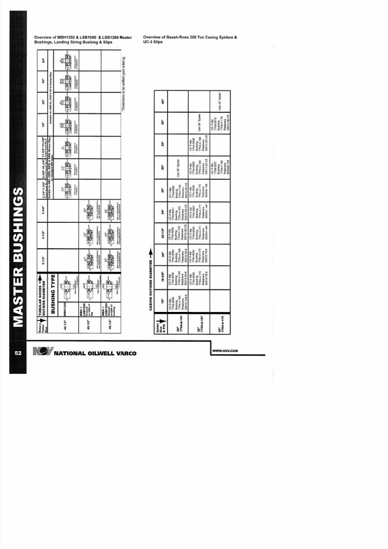
7/25/2019 Rotary Care & Maintenance Handbook
http://slidepdf.com/reader/full/rotary-care-maintenance-handbook 54/116
i
~
-
i
o-
i
m
a
I
z
o no
3
R
o
a
y
T
B
L
G
O
O
D
S
~
T
e
O
U
T
D
E
D
I
A
M
E
5
.
1
/
2
S
z
B
S
I
N
G
T
4
9
.
1
/
2
M
B
~
H
,
1
M
B
o
M
B
+
L
]
5
4
9
.
1
/
2
D
r
e
.
•
w
1
T
s
p
M
B
Q
"
M
B
w
/
0
•
C
s
p
M
B
+
~
L
S
4
9
.
1
/
2
D
r
e
-
,
"
.
•
w
/
1
b
n
M
B
p
5
M
B
S
&
C
o
b
o
n
C
A
N
G
O
U
T
D
E
D
I
A
M
E
S
P
i
d
S
z
&
P
N
1
1
8
-
5
/
8
2
U
3
s
p
U
3
s
p
U
3
s
p
7
5
7
5
7
5
3
B
n
B
n
B
n
7
A
1
7
A
1
7
A
1
7
A
1
R
a
n
s
R
a
n
s
R
a
n
s
5
1
8
5
5
8
5
5
8
U
3
s
p
U
3
s
p
7
5
7
5
3
B
n
B
n
7
A
1
7
A
1
7
A
1
R
a
n
s
R
a
n
s
5
7
8
5
7
8
4 7
A
1
-
5
.
7
/
8
S
S
,
.
•
M
S
w
I
L
5
&
s
S
7
S
,
.
•
M
B
S
&
b
.
2
2
-
1
/
2
U
3
s
p
7
5
B
n
7
A
1
R
a
n
s
5
3
C
U
3
s
p
7
5
B
n
7
A
1
R
a
n
s
9
4
6
.
5
/
8
6
5
"
.
•
M
B
w
/
s
6
6
,
.
•
M
B
w
L
5
&
2
U
3
s
p
7
5
B
n
7
A
1
R
a
n
s
5
3
C
U
3
s
p
7
5
B
n
7
A
1
R
a
n
s
9
4
2
.
3
/
8
7
.
5
/
8
9
.
5
/
8
1
0
.
3
/
4
1
1
.
3
/
4
1
3
.
3
/
8
1
2
2
2
I
b
w
N
3
b
w
N
2
I
b
w
N
1
S
u
a
e
o
5
S
S
M
L
S
X
&
S
H
L
R
o
a
S
l
p
S
e
M
S
X
D
&
C
S
C
n
S
p
w
d
A
a
u
•
"
•
•
-
1
-
1
3
•
2
1
3
S
•
O
M
B
&
1
M
B
&
1
2
M
B
&
1
1
c
n
n
1
C
l
n
X
G
h
g
C
p
p
p
p
p
p
p
'
D
m
e
o
o
b
v
e
u
o
d
2
3
3
3
4
U
3
s
p
7
5
B
n
U
3
S
d
7
A
1
R
a
n
s
5
2
C
U
3
s
p
U
3
s
p
U
3
s
p
7
5
7
5
7
5
B
n
B
n
B
n
7
A
1
7
A
1
7
A
1
U
3
S
d
R
a
n
s
R
a
n
s
R
a
n
s
9
1
5
3
C
5
2
C
U
3
S
p
U
3
s
p
7
5
7
5
B
n
B
n
U
4
S
d
7
A
1
7
A
1
R
a
n
s
R
a
n
s
9
7
5
3
C
-
-
0
C
<
I
C
:
<
:
_
(
Q
C
I
:
E
-
a
s
c
0
l
S
(
Q
.
.
0
5
'
~
Q
.
0
C
c
0
I
.
:
O
_
0
~
~
~
C
J
:
C
C
I
.
NC
1
o s
I I
I
.
C0
<
•
C
(
<
C
J
_
€
I
0
[
I I
I : :
0
g
I
N
o
o
: o
I
I
s
(
Q
C
J
C
c
C
(
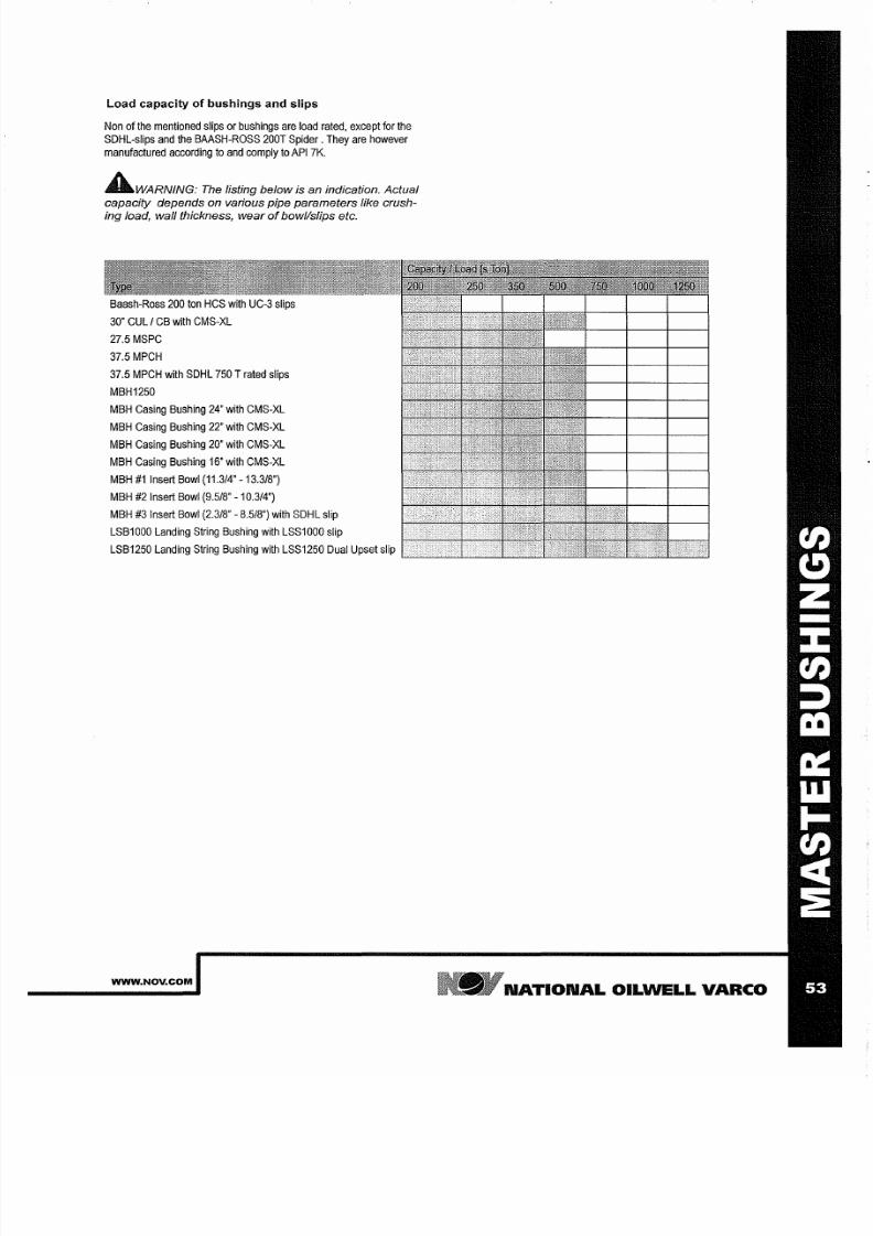
7/25/2019 Rotary Care & Maintenance Handbook
http://slidepdf.com/reader/full/rotary-care-maintenance-handbook 55/116
oad capacity of bushings and slips
Non of the mentioned slips or bushings are load rated, except for the
SDHL-slips
and the
BAASH-ROSS 200T
Spider. They
are however
manufactured according
to
and comply
to API 7K.
AWARNING
The
listing below is an indication. Actual
capacity depends
on
various pipe parameters like crush-
ing load wall thickness wear
of
bowl/slips etc.
Baash-Ross
200 ton HCS with UC-3
slips
30
CUL I CB with CMS-XL
27.5 MSPC
37.5 MPCH
37.5
MPCH
with
SDHL 750
T rated slips
MBH1250
MBH Casing Bushing 24 with CMS-XL
MBH Casing Bushing
22
with CMS-XL
MBH
Casing
Bushing 20 with CMS-XL
MBH Casing Bushing 16
with
CMS-XL
MBH
1 Insert
Bowl (11.3/4
-13.3/8 )
MBH #2
Insert
Bowl (9.5/8 -10.3/4 )
MBH #3
Insert
Bowl (2.318
8.518 )
with SDHL slip
LSB1000 Landing String Bushing with LSS1000 slip
LSB1250 Landing
String Bushing
with LSS1250 Dual
Upset slip
~ ~ ~ ~ ~ ~ ~
WWW NOV COM
N TION L OILWELL VARCO
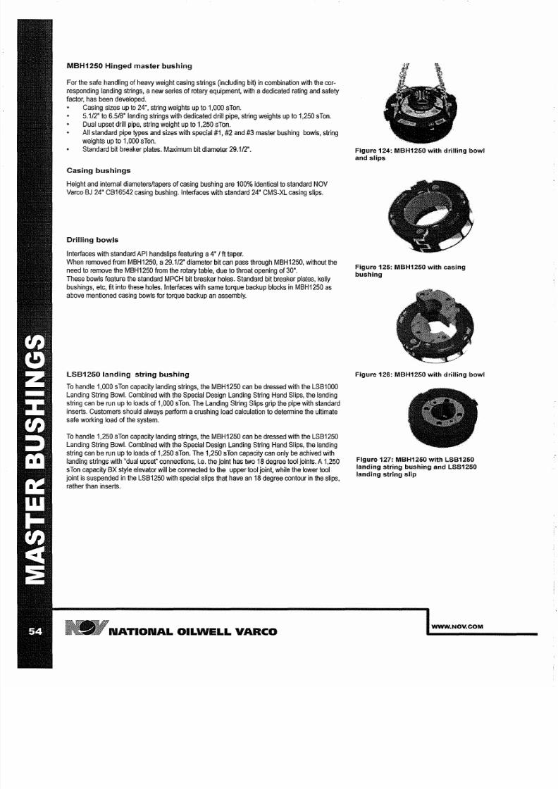
7/25/2019 Rotary Care & Maintenance Handbook
http://slidepdf.com/reader/full/rotary-care-maintenance-handbook 56/116
MBH125 Hinged master bushing
For the safe handling of heavy weight casing strings (including bit) in combination
with the
cor
responding landing
strings, anew
series
of rotary equipment, with a
dedicated
rating and
safety
factor, has been developed.
Casing sizes
up to 24',
string weights
up to 1,000
sTan.
5.1/2 to 6.5/8' landing strings
with
dedicated drill pipe, string
weights
up to
1,250 sTon.
Dual upset drill pipe,
string
weight up to
1,250
sTon.
All standard
pipe types and
sizes
with
special #1,
#2 and #3
master bushing
bowls, string
weights
up
to 1,000 sTon.
Standard
bit breaker plates. Maximum bit diameter
29.1/2 .
Casing bushings
Height and internal
diameters/tapers
of casing bushing are 100%
identical
to standard OV
Varco J 24 CB16542
casing
bushing.
Interfaces with standard
24 CMS-XL
casing
slips.
Drilling bowls
Interfaces with
standard API handslips featuring a4 t
taper.
When removed from MBH1250, a29.1/2 diameter bit can pass through MBH1250, without the
need to
remove
the MBH1250 from the rotary
table,
due to throat opening of 30 .
These bowls
feature
the standard MPCH bit
breaker holes.
Standard bit
breaker plates,
kelly
bushings, etc, it
into these holes. Interfaces with
same
torque
backup
blocks in
MBH1250 as
above
mentioned
casing bowls for
torque
backup an assembly.
LSB125 landing string bushing
To handle 1,000
sTon capacity
landing strings, the
MBH1250
can be dressed
with
the
LSB1000
Landing String Bowl. Combined with the Special Design Landing String Hand Slips, the landing
string can be run up to loads of 1,000 sTan. The Landing String
Slips
grip the pipe with standard
inserts. Customers
should
always
perform
a
crushing load
calculation
to
determine the
ultimate
safe working load of the system.
To handle
1,250 sTon capacity
landing strings, the
MBH1250
can be dressed
with the LSB1250
Landing String Bowl. Combined with the Special Design Landing String Hand Slips, the landing
string
can
be
run up to loads of 1,250 sTon. The
1,250
sTon
capacity
can only be achived with
landing
strings with dual
upset' connections,
i.e.
the joint has
two
18
degree
tool
jOints.
A
1,250
sTon capacity BX style elevator will be
connected
to the upper tool joint, while the lower
tool
joint
is
suspended
in the LSB1250 with
special
slips that
have
an 18
degree contour in the slips,
rather
than
inserts.
N TION L OILWELL V RCO
Figure 124: MBH125 with drilling bowl
and slips
Figure 125: MBH125 with casing
bushing
Figure 126: MBH125 with drilling bowl
Figure 127: MBH125 with LSB125
landing string bushing and LSS125
landing string Slip
WWW NOV COM
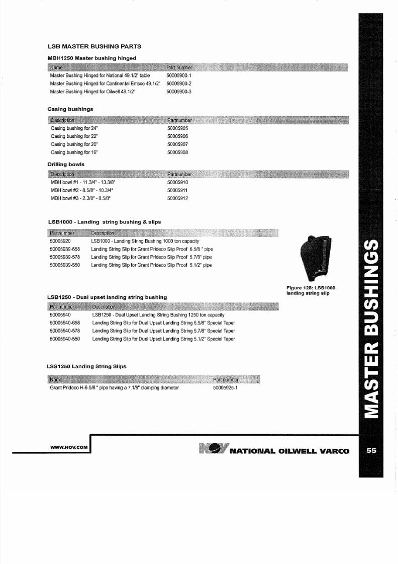
7/25/2019 Rotary Care & Maintenance Handbook
http://slidepdf.com/reader/full/rotary-care-maintenance-handbook 57/116
LSB M STER BUSHING PARTS
MBH1250 Master bushing hinged
Master
Bushing Hinged
for
National
49.1/2 table 50005900-1
Master Bushing
Hinged
for Continental
Emsco 49.1/2 50005900-2
Master Bushing Hinged for
OilweIl49.1/2'
50005900-3
Casing bushings
Casing
bushing for 24'
Casing bushing
for
22'
Casing bushing
for 20'
Casing bushing for 16'
Drilling bowls
MBH bowl 1
-11.3/4 -13.3/8
MBH
bowl
#2 - 8.5/8'
-10.3/4
MBH bowl #3
-
2.3/8'
-
8.5/8
LSB1000 - Landing string bushing slips
50005905
50005906
50005907
50005908
50005910
50005911
50005912
50005920
50005939-658
50005939-578
50005939-550
LSB1000
-
Landing String Bushing 1000
ton
capacity
Landing String
Slip for
Grant Prideco
Slip
Proof
6.5/8
pipe
Landing String Slip for
Grant Prideco
Slip Proof 5.7/8 pipe
Landing
String Slip for Grant Prideco Slip Proof 5.1/2
pipe
LSB1250 - Dual upset landing string bushing
50005940
50005940-658
50005940-578
50005940-550
LSB1250
-Dual
Upset Landing String
Bushing 1250
ton capacity
Landing String Slip
for
Dual
Upset
Landing String 6.5/8 Special Taper
Landing String Slip for Dual Upset Landing String 5.7/8 Special
Taper
Landing String Slip
for
Dual
Upset
Landing String 5.1/2 Special Taper
LSS1250 Landing String Slips
Grant Prideco H-6.5/8
pipe having a7.1/8' clamping diameter
50005925-1
Figure 128: LSS1000
landing string slip
WWW NOV COM
N TION L OILWELL V RCO

7/25/2019 Rotary Care & Maintenance Handbook
http://slidepdf.com/reader/full/rotary-care-maintenance-handbook 58/116
N TION L
OILWELL
V RCO
WWW NOV COM
7/25/2019 Rotary Care & Maintenance Handbook
http://slidepdf.com/reader/full/rotary-care-maintenance-handbook 59/116
H ND SLIPS
WWW NOV COM
N TION L OILWELL VARCO
7/25/2019 Rotary Care & Maintenance Handbook
http://slidepdf.com/reader/full/rotary-care-maintenance-handbook 60/116
N TION L OILWELL V RCO
WWW NOV COM
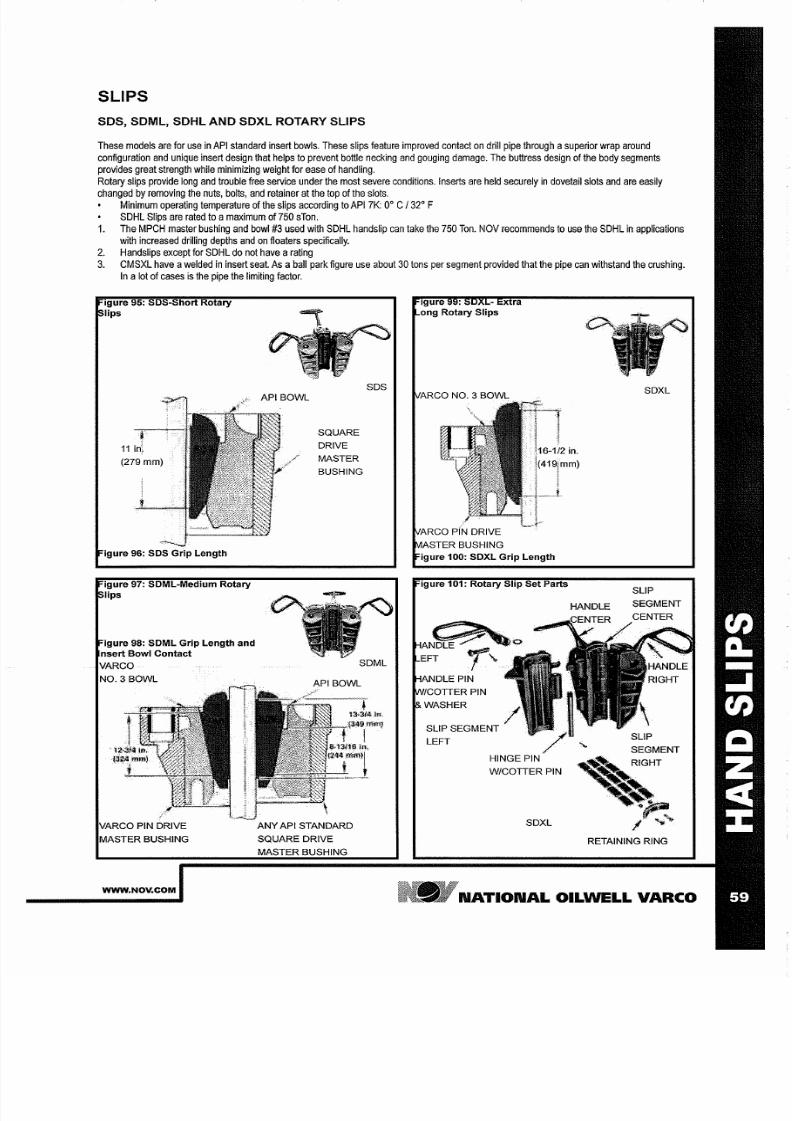
7/25/2019 Rotary Care & Maintenance Handbook
http://slidepdf.com/reader/full/rotary-care-maintenance-handbook 61/116
SLIPS
SOS SOML SDHL
AND SDXL
ROTARY
SLIPS
These models
are for use in API standard insert bowls. These
slips
feature improved contact on drill
pipe through
asuperior wrap around
configuration and unique insert design that helps
to
prevent bottle necking and gouging damage. The buttress design of
the
body segments
provides great strength
while minimizing
weight for
ease
of
handling.
Rotary slips provide
long and
trouble free service under
the
most
severe conditions. Inserts
are
held
securely
in
dovetail slots
and
are easily
changed by removing
the nuts,
bolts, and
retainer at
the
top of
the
slots.
Minimum operating
temperature
of the slips according to
API
7K: 0° C
3 °
F
SDHL
Slips
are rated to a maximum
of 750
sTon.
1.
The
MPCH
master bushing
and bowl 3
used with
SDHL
hands
ip can take
the
750 Ton
NOV
recommends to use
the SDHL
in
applications
with increased
drilling
depths and on floaters specifically.
2. Handslips
except
for SDHL do not have a rating
3. CMSXL have awelded in insert
seat.
As aball park figure use about
30
tons per
segment
provided that the pipe can
withstand
the crushing.
In a ot
of
cases
is
the pipe the
limiting
factor.
igure 95: 50S Short Rotary
lips
igure 96: 50S Grip Length
igure 97: SOML Medium Rotary
lips
igure 98: SOML Grip Length and
nsert Bowl Contact
VARGO
NO 3 BOWL
VARGO
PIN
DRIVE
MASTER BUSHING
WWW NOV COM
SQUf\RE
DRIVE
MASTER
BUSHING
ANY API STANDARD
SQUARE DRIVE
MASTER BUSHING
SDS
Igure x ra
ong Rotary Slips
f\RGO
NO 3
BOWL
LEFT
HINGE PIN
W GOTTER PIN
SDXL
HANDLE
SDXL
SLIP
SEGMENT
RETAINING RING
NATIONAL
OILWELL
VARCO
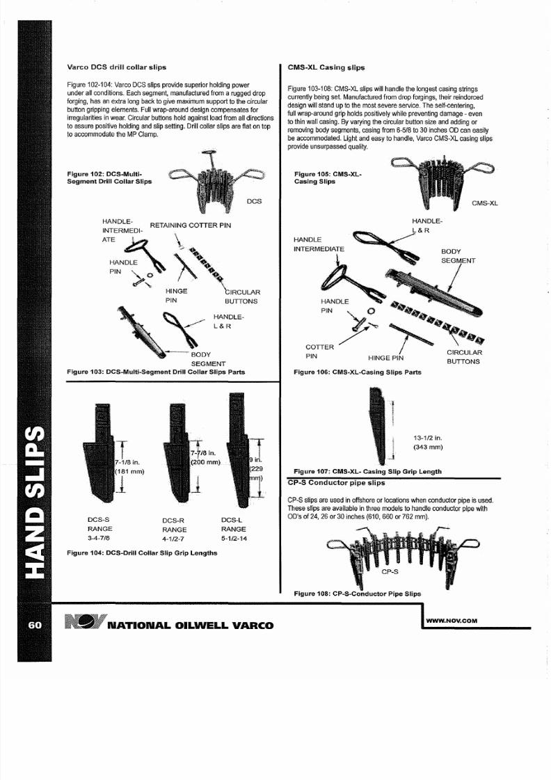
7/25/2019 Rotary Care & Maintenance Handbook
http://slidepdf.com/reader/full/rotary-care-maintenance-handbook 62/116
Varco DCS drill collar
slips
Figure
102-104:
Varco
DCS slips provide
superior holding power
under all conditions.
Each
segment, manufactured from a rugged drop
forging,
has
an extra long back to
give
maximum support to the circular
button
gripping elements.
Full wrap-around design
compensates
for
irregularities
in
wear.
Circular
buttons
hold
against
load from
all
directions
to
assure positive holding
and
slip setting. Drill collar slips are
flat
on top
to accommodate the MP Clamp.
Figure 102: DCS-Multi
Segment
Drill
Collar
Slips
HANDLE- RETAINING COTTER
PIN
INTERMEDI-. . \
ATE
~ ; ; .......
.
'.
. .
. .
HANDLE . .
\ 1
PIN
>0 \
...
HINGE \1
RCULAR
PIN
BUTTONS
HANDLE
L R
Figure 103: DCS-Multi-Segment Drill Collar
Slips
Parts
DCS-S
RANGE
3-4-7/8
DCS-R
RANGE
4-1/2-7
in.
mm)
Figure 104: DCS-Drill Collar Slip Grip Lengths
DCS-L
RANGE
5-1/2-14
N TION L OILWELL V RCO
CMS-XL Casing slips
Figure 103-108: CMS-XL
slips will
handle
the
longest casing strings
currently being set. Manufactured from drop forgings, their reindorced
design will stand up to the
most severe service.
The
self-centering,
full
wrap-around
grip
holds
positively
while preventing
damage - even
to thin wall casing.
By
varying the
circular
button size
and
adding or
removing body segments, casing from 6-5/8 to 30 inches 00 can easily
be accommodated.
Light
and easy to handle, Varco CMS-XL casing
slips
provide
unsurpassed quality.
Figure 105:
CMS-Xl
Casing Slips
HANDLE-
HANDLE
INTERMEDIATE
~
BODY
HANDLE
PIN
.....
COTTER
PIN
..
' ~ ~
INGE PIN
Figure 106: CMS-Xl-Casing Slips Parts
13-112
in.
(343
mm)
Figure 107:
CMS-Xl-
Casing Slip Grip
length
CpOS
Conductor
pipe
slips
BUTTONS
CPOS slips are used in
offshore
or locations when conductor pipe is used.
These
slips
are
available
in three models to handle
conductor
pipe with
OD s of
24
26 or 30
inches
(610,
660
or 762
mm).
Figure 108: CPoS-Conductor Pipe
Slips
WWW NOV COM
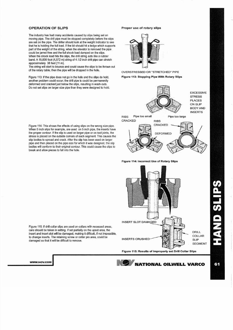
7/25/2019 Rotary Care & Maintenance Handbook
http://slidepdf.com/reader/full/rotary-care-maintenance-handbook 63/116
OPERATION OF SLIPS
The
industry has had many
accidents
caused by
slips being
set on
moving pipe. The drill pipe must be stopped completely before the slips
are set on the
pipe.
The
driller
should
look at the weight indicator to see
that he is holding the full load. If the bit should hit a edge
which
supports
part of the weight of
the
string,
when the
elevator
is
removed
the
pipe
could
be
jarred free
and
the full shock load
dumped on
the slips.
When the shock load hits the
slips,
the drill
string
acts
like
a rubber
band. A
15,000
foot 4,572 m)
string
of
4 1/2
inch
drill pipe
can
stretch
approximately 38
feet 11 m).
The string will
start
to bounce
and
could cause the slips to
be
thrown
out
of
the
rotary
table;
then the
pipe
will be
dropped
in the hole.
Figure
113:
If the pipe does not go in the hole
and
the slips do hold,
another
problem could
occur; the
drill
pipe
is
could be permanently
deformed and
cracked
just
below the
slips,
resulting
in
wash-outs.
Do
not set
slips on larger size pipe than they were designed to
hold.
Figure 114: This
shows
the effects of using
slips on
the wrong
size
pipe.
When
5
nch
slips
for example, are used on
5
nch
pipe,
the
inserts have
the proper contour.
If
the slip is used on larger pipe or
on
tool joints, the
stress is placed on the
outside
corners
of
each segment.
This
causes
the
slip
bodies to spread and
crack.
After the slip has been used
on
larger
pipe and then placed on the pipe size for which it was designed, the slip
bodies will conform to
their
original
contour. This could
cause
the
slips to
break and allow pieces to fall
into
the hole.
Figure
115: If
drill
collar
slips are used
on
collars
with
recessed areas,
care should be taken in setting.
If
set partially on the upset area, the
insert
and
insert slot
will
be damaged, making
it
difficult, if not
impossible,
to change
inserts.
The retaining screw
or cotter pin area,
could
be
damaged so that it will
be difficult
to remove.
WWW NOV COM
Proper use
of
rotary slips
OVERSTRESSED OR STRETCHED PIPE
Figure 3: Stopping Pipe With Rotary Slips
RIBS Pipe too small
Pipe too large
CRACKED
Figure 4: Incorrect Use of Rotary Slips
EXCESSIVE
STRESS
PLACES
ON SLIP
BODY AND
INSERTS
DRILL
COLLAR
SLIP
SEGMENT
Figure 5: Results of Improperly set Drill Collar Slips
N TION L OILWELL V RCO
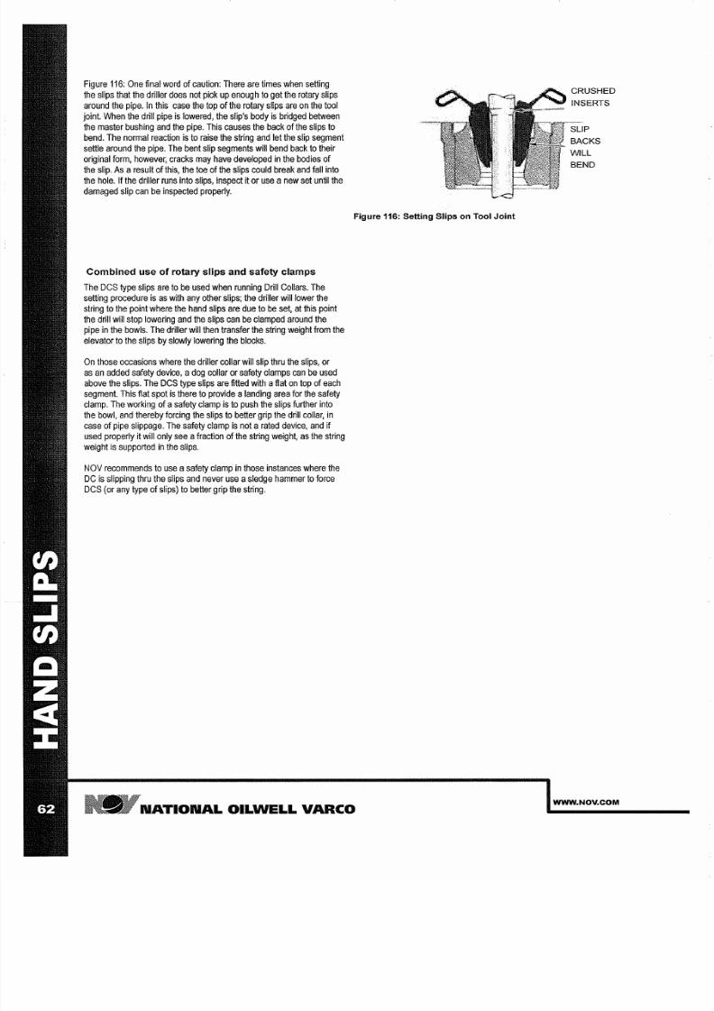
7/25/2019 Rotary Care & Maintenance Handbook
http://slidepdf.com/reader/full/rotary-care-maintenance-handbook 64/116
Figure
116:
One final
word of
caution: There are
times when
setting
the slips that the
driller
does not pick up enough to
get
the rotary slips
around the pipe. In this case the top of the
rotary
slips are on the tool
joint.
When
the drill pipe
is lowered,
the
slip s body is bridged
between
the master bushing and
the
pipe. This causes the back
of the slips to
bend. The normal reaction is to raise the string and let the slip
segment
settle
around the pipe. The bent slip segments will bend
back
to their
original form, however,
cracks may
have developed in
the bodies of
the slip.
As
result
of this, the toe of
the
slips could break
and fall into
the hole. If the driller runs
into slips,
inspect
it
or use new set
until
the
damaged
slip
can
be
inspected properly.
Combined use
of
rotary slips and safety clamps
The
DCS type slips are to be used when running Drill Collars. The
setting procedure is
as with
any other slips;
the driller will lower the
string
to
the
point
where the
hand
slips
are due to
e
set,
at
this
point
the drill will
stop
lowering
and
the slips can be clamped around the
pipe in
the
bowls.
The
driller will then transfer the
string weight
from the
elevator to the slips
by slowly lowering the blocks.
On those
occasions
where the driller collar will
slip
thru
the
slips, or
as
an added safety device, dog collar or safety clamps
can
be
used
above the slips. The DCS type slips are fitted with
lat on
top of each
segment. This fiat
spot
is
there
to
provide anding area
for
the safety
clamp. The
working
of safety clamp
is to push the
slips further into
the bowl, and thereby forcing the slips to better grip the drill collar, in
case of
pipe slippage.
The
safety clamp
is not rated
device,
and
if
used
properly it will
only
see raction
of
the string weight,
as
the string
weight
is
supported in the slips.
NOV recommends to
use
safety
clamp
in
those
instances where the
DC
is
slipping
thru the slips and
never
use sledge hammer to
force
DCS (or any
type of slips) to
better
grip the
string.
Figure 6: Setting Slips on Tool Joint
N TION L
OILWELL
V RCO
WWW NOV COM
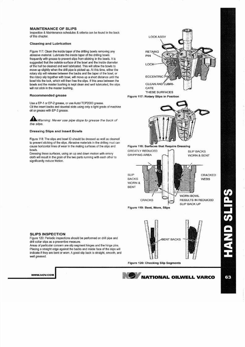
7/25/2019 Rotary Care & Maintenance Handbook
http://slidepdf.com/reader/full/rotary-care-maintenance-handbook 65/116
MAINTENANCE OF SLIPS
Inspection Maintenance schedules criteria
can be found
n
the back
of this chapter.
Cleaning and Lubrication
Figure 117: Clean the
inside taper
of the drilling
bowls
removing any
abrasive material. Lubricate
the inside taper
of the
drilling bowls
frequently with grease to prevent slips
from
sticking n
the bowls. It
is
suggested that the outside surface
of
the bowl and the inside diameter
ofthe
hull be
cleaned
and
well
lubricated. This
will
allow the bowls to
move up
slightly
when
the drill
pipe is picked up.
At
this
time either
the
rotary slip will release between the backs and the
taper
of the bowl or
the rotary slip together with bowl will move
up a
short
distance
until
the
bowl hits the lock
which
will
then free the slips.
If
this
area between the
bowls
and
the master
bushing is kept clean and
well lubricated the
slips
will not stick n the
master bushing.
Recommended grease
Use a EP-1 or
EP-2
grease or
use Autol
TOP2000
grease.
Oil
the
insert
backs
and
dovetail slots
using
only
a
ight
grade of
machine
oil or grease with EP-2 grease.
AWarning Never us pipe dope to grease th back of
the slips
Dressing Slips and Insert Bowls
Figure 118: The slips and bowllD should be
dressed
as well as cleaned
to prevent sticking of
the slips.
Abrasive materials n
the
drilling
mud can
cause horizontal lines of wear n the mating surfaces of the slips and
bowls.
Dressing these
surfaces
using an up and
down
motion
with
emery
cloth
will result in the
grain
of the two parts running with each other
to
significantly
reduce
friction.
SLIPS INSPECTION
Figure 120: Periodic inspections should be performed
on
drill pipe and
drill
collar
slips
as a
preventive
measure.
Areas of particular
concern
are slip segment hinges
and
the
hinge
pins.
Placing
a
straight edge against the backs and inside face of the slips will
indicate if
they
are bent or worn.
A
good slip
back
is straight smooth and
well
greased.
WWW NOV COM
THESE SURFACES
Figure 117: Rotary Slips n Position
Figure 118: Surfaces that Require Dressing
GREATLY REDUCED
GRIPPING AREA
SLIP
BACKS
WORN
BENT
Figure 119: Bent Worn Slips
SLIP BACKS
WORN BENT
CRACKED
WEBS
RESULTS IN REDUCED
SLIP BACK UP
BACKS
Figure 120: Checking Slip Segments
N TION L OILWELL V RCO
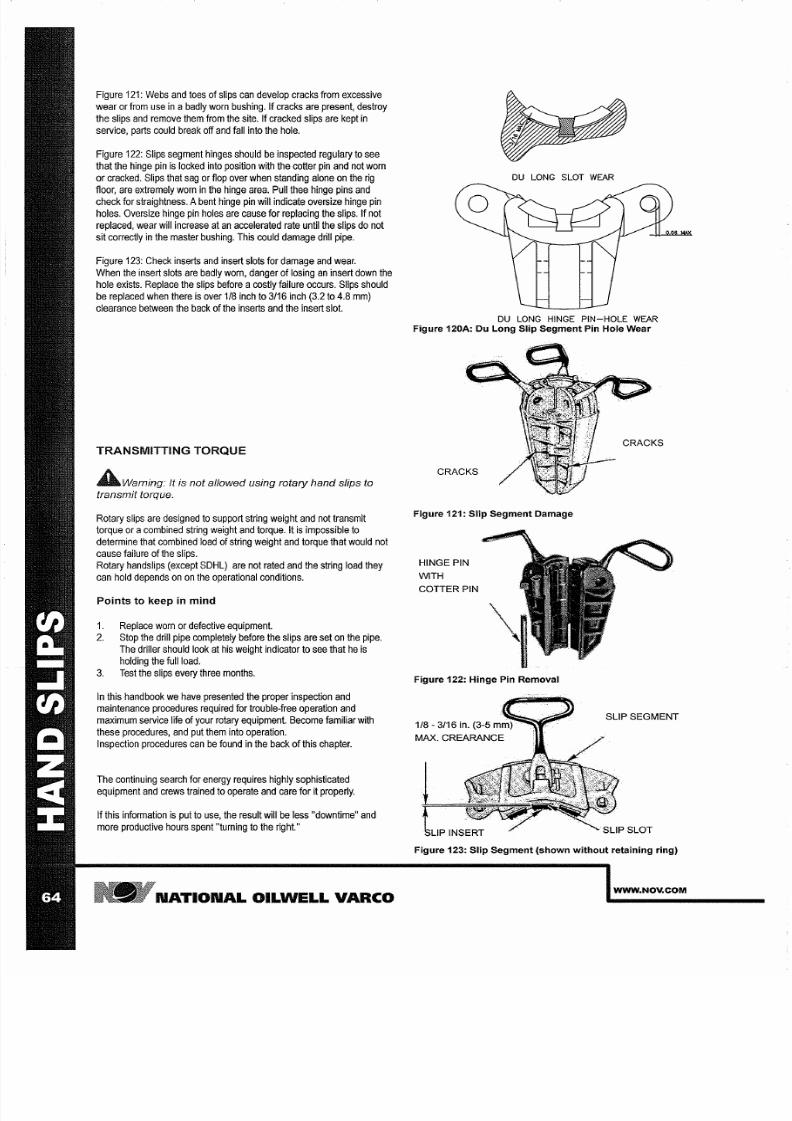
7/25/2019 Rotary Care & Maintenance Handbook
http://slidepdf.com/reader/full/rotary-care-maintenance-handbook 66/116
Figure 121:
Webs
and
toes of
slips can develop cracks
from
excessive
wear or from
use
in abadly worn bushing. If cracks are present, destroy
the slips
and
remove them from the site. If cracked slips are kept in
service,
parts
could break off and fall into the hole.
Figure 122: Slips
segment
hinges should be
inspected
regulary to see
that the
hinge
pin
is locked
into
position
with the cotter pin and not
worn
or cracked.
Slips that
sag or
flop over when standing
alone
on the
rig
floor, are extremely worn in the hinge
area.
Pull thee hinge pins and
check for straightness. Abent hinge pin will indicate oversize hinge pin
holes. Oversize
hinge
pin holes
are cause for
replacing
the slips. If
not
replaced, wear
will
increase at
an
accelerated rate until
the
slips do
not
sit correctly in the
master
bushing. This could
damage
drill pipe.
Figure 123: Check inserts and insert slots
for
damage and wear.
When the insert slots are badly worn, danger of losing an insert down the
hole
exists. Replace the slips before acostly failure occurs. Slips should
be replaced
when
there
is
over 1 8 inch
to
3 16
inch (3.2 to
4.8
mm)
clearance between the back
of
the
inserts and the
insert slot.
TRANSMITTING TORQUE
AWarn ing
It is not allowed using rotary hand slips
to
transmit torque
Rotary
slips are designed
to
support
string
weight
and
not
transmit
torque or acombined string weight
and
torque.
It is
impossible
to
determine that combined load of string weight
and
torque
that
would not
cause failure
of the slips.
Rotary
handslips
(except SDHL) are
not
rated and
the string load they
can hold depends
on
on the operational conditions.
Points to keep
n
mind
1. Replace
worn or defective
equipment.
2. Stop the drill pipe completely
before the slips
are set
on the pipe.
The driller should look at his weight indicator to see that
he is
holding the
full
load.
3
Test
the slips every
three months.
In this handbook we have presented the
proper inspection
and
maintenance procedures required for trouble-free operation
and
rnaximum service life of
your
rotary equipment. Become familiar with
these procedures, and
put them into operation.
Inspection
procedures can be
found in
the back of this chapter.
The continuing
search
for
energy requires
highly sophisticated
equipment and crews
trained to operate and
care
for
it properly.
If this
information
is put to use, the
result
will be
less
downtime and
more
productive
hours spent turning
to
the
right.
N TION L OILWELL V RCO
DU LONG
SLOT
WE R
DU LONG HINGE
PIN HOLE
WE R
Figure 120A: Du Long Slip Segment Pin Hole Wear
Figure 121: Slip Segment Damage
HINGE PIN
WITH
COTTER PIN
Figure 122: Hinge Pin Removal
SLIP SEGMENT
Figure 123: Slip Segment shown without retaining ring)
WWW NOV COM
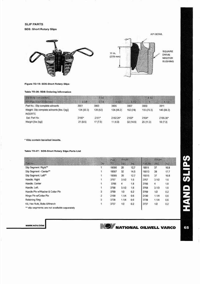
7/25/2019 Rotary Care & Maintenance Handbook
http://slidepdf.com/reader/full/rotary-care-maintenance-handbook 67/116
SLIP PARTS
SOS: Short Rotary Slips
Figure TO 15: SOS Short Rotary Slips
Table TO 26: SOS Ordering Information
Part
No.:
Slip complete wlinserts
3901
3903
Weight:
Slip complete w/inserts
[Ibs (kg)]
134 (60.3) 128 (52)
INSERTS
Set: Part
No
2160* 2161*
Weight
[Ibs
(kg)]
2
(9.5) 17 (7.6)
*
Kits contain bevelled inserts.
Table TO 27: SOS Short Rotary Slips Parts List
Slip
Segment. Right**
Slip Segment - Center**
Slip
Segment.
Left**
Handle. Right
Handle. Center
Handle. Left.
Handle
Pin
w/Washer Cotter
Pin
3
Hinge
Pin w/Cotter
Pin
2
Retaining
Ring
3
Kit,
Hex Nuts, Bolts Wrench
**
slip
segments are
not
available
separately
WWW NOV COM
3905 3907
124
(56.2)
162 (74)
2162.24* 2163*
(4.9) 32 (14.5)
19306 28 12,7
19307
32 14.5
19305
28
12.7
3767
3 1/2
1.6
3766 4
1.8
3768
3 1/2
1.6
3769 1/2
0.2
2190
1 1/4
0.6
3738
1 1/4
0.6
3737 1/2
0.2
API BOWL
3909
155 (70.3)
2164*
25
(11.3)
93
19313
19315
3767
3766
3768
3769
2190
3739
3737
SQUARE
DRIVE
MASTER
BUSHING
39
146
(66.2)
2165.36*
16 (7.3)
37
16.8
39 17.7
37
16.8
3 1/2
1.6
4
1.8
3 1/3
1.5
1/2
0.2
1 1/4
0.6
1 1/4
0.6
1/2
0.2
N TION L OILWELL V RCO
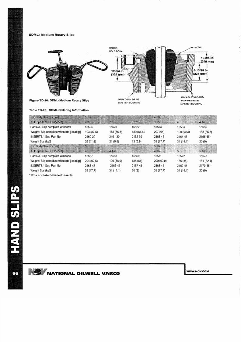
7/25/2019 Rotary Care & Maintenance Handbook
http://slidepdf.com/reader/full/rotary-care-maintenance-handbook 68/116
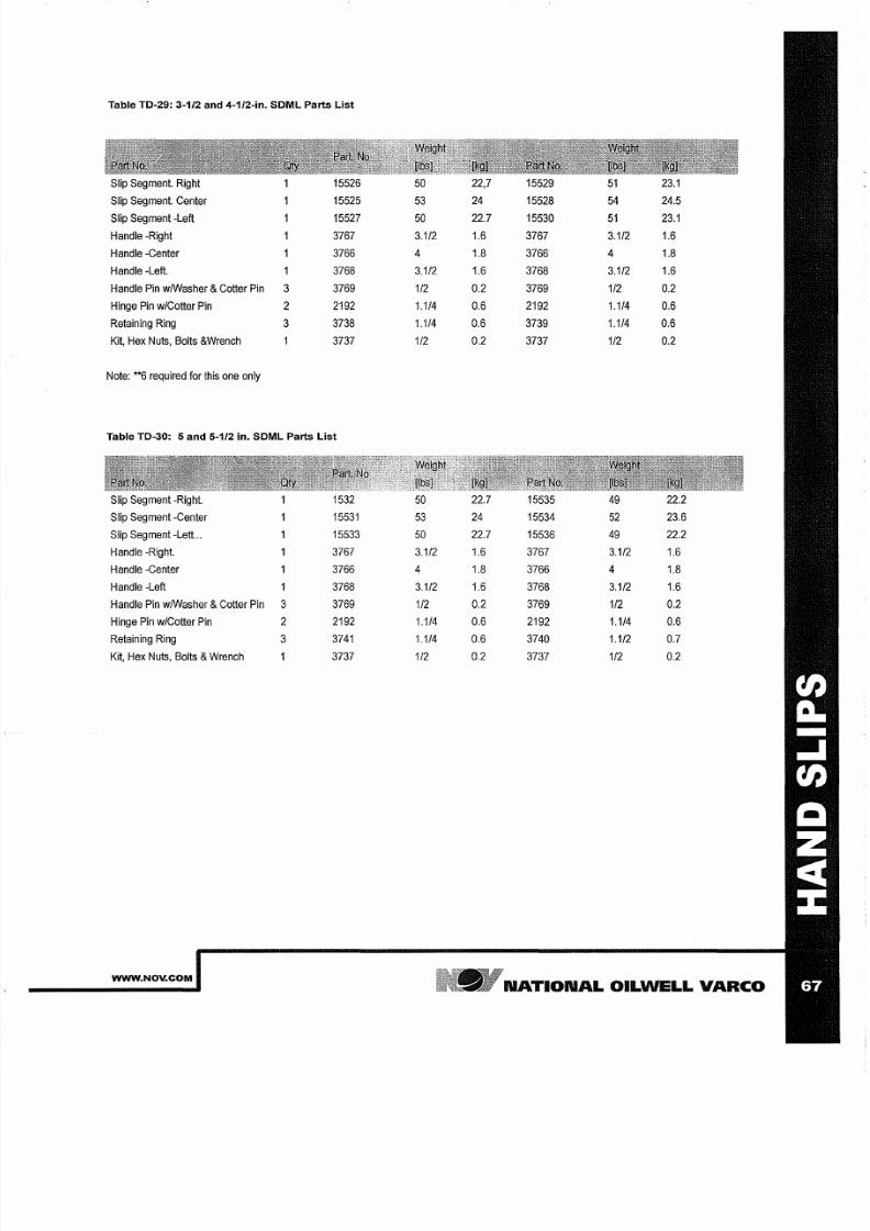
7/25/2019 Rotary Care & Maintenance Handbook
http://slidepdf.com/reader/full/rotary-care-maintenance-handbook 69/116
Table TO 29: 3 1/2 and 4 1/2 in. SOML Parts List
Slip
Segment. Right 15526
50
22,7
15529
51
23.1
Slip Segment. Center
15525
53
24
15528 5 24.5
Slip Segment
-Left 15527 50
22.7
15530
51 23 1
Handle
-Right 3767
3 1/2
1.6 3767
3 1/2
1.6
Handle -Center 3766
4
1.8 3766
4
1.8
Handle
-Left.
1 3768
3 1/2 1.6 3768
3 1/2 1.6
Handle
Pin
wlWasher Cotter Pin
3
3769 1/2 0.2 3769 1/2 0.2
Hinge
Pin w/Cotter Pin 2 2192 1 1/4
0.6
2192 1 1/4
0.6
Retaining Ring
3
3738 1 1/4 0.6 3739
1 1/4
0.6
Kit,
Hex Nuts,
Bolts
Wrench
3737
1/2
0.2 3737
1/2
0.2
Note:
**6
required for
this one only
Table TO 30: 5 and 5 1/2 in. SOML Parts List
Slip Segment -Right.
1532
50
22.7 15535
49
22.2
Slip
Segment
-Center
15531
53
24
15534 52
23.6
Slip Segment -Lett .. 15533
50
22.7 15536
49
22.2
Handle -Right.
3767
3 1/2 1.6 3767 3 1/2 1.6
Handle
-Center
3766
4
1.8
3766
4
1.8
Handle -Left
1
3768
3 1/2 1.6
3768
3 1/2 1.6
Handle
Pin
wlWasher Cotter
Pin 3
3769
1/2
0.2
3769
1/2
0.2
Hinge
Pin
w/Cotter
Pin
2 2192 1 1/4
0.6 2192
1 1/4 0.6
Retaining
Ring
3
3741 1 1/4
0.6 3740
1 1/2
0.7
Kit, Hex Nuts,
Bolts
Wrench
3737
1/2
0.2 3737
1/2
0.2
WWW NOV COM
N TION L OILWELL V RCO
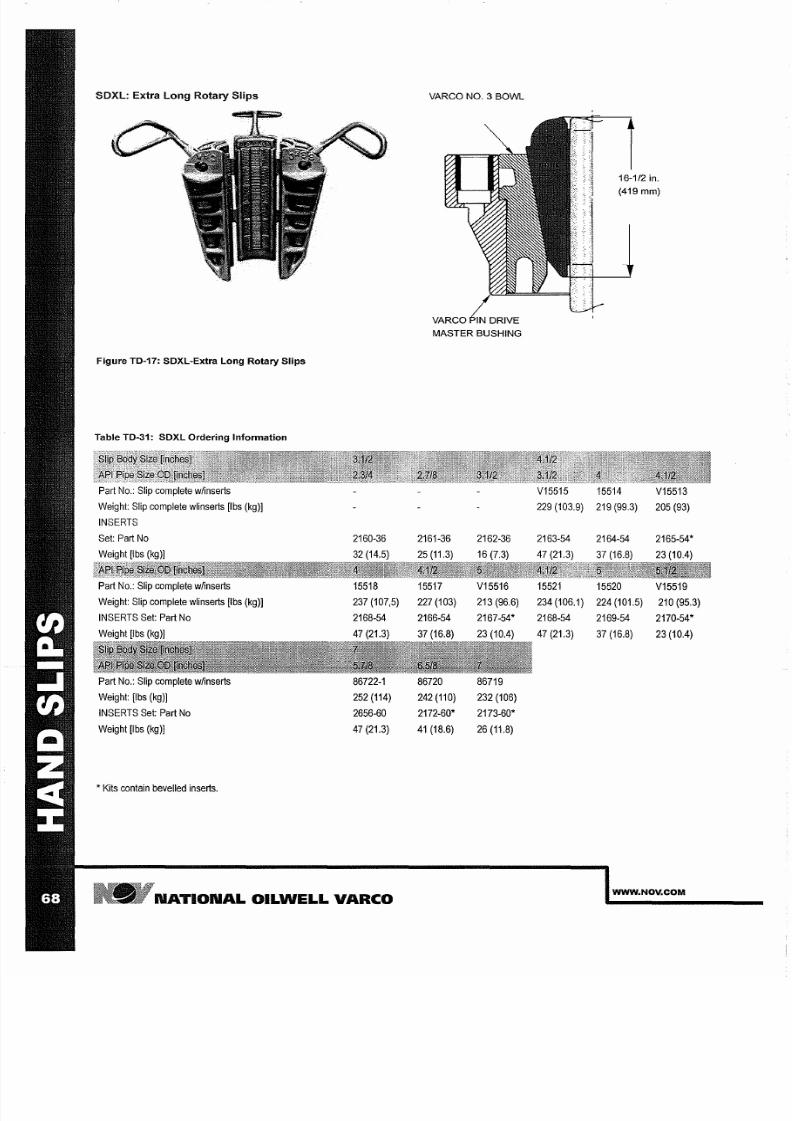
7/25/2019 Rotary Care & Maintenance Handbook
http://slidepdf.com/reader/full/rotary-care-maintenance-handbook 70/116
SDXL: Extra Long Rotary Slips
Figure TD-17: SDXL Extra Long
Rotary
Slips
Table TD-31: SDXL Ordering
Information
Part
No.:
Slip complete wiinserts
Weight:
Slip
complete wlinserts [Ibs kg)]
INSERTS
Part No.: Slip complete
wiinserts
Weight: Slip complete wlinserts
[Ibs
kg)]
INSERTS
Set: Part No
Weight [Ibs kg)]
Part
No.:
Slip complete wiinserts
Weight:
[Ibs kg)]
INSERTS Set: Part No
Weight [Ibs kg)]
, Kits
contain bevelled inserts.
15518
237
(107,5)
2168-54
47 (21.3)
86722-1
252 (114)
2656-60
47
(21.3)
N TION L OILWELL
V RCO
VARCO
NO.3
BOWL
VARCO N DRIVE
MASTER BUSHING
15517
227
(103)
2166-54
37 (16.8)
86720
242
(110)
2172-60
4
(18.6)
V15516
213
(96.6)
2167-54
23 (10.4)
86719
232 (106)
2173-60
26 (11.8)
16-112 in.
419
mm)
V15515 15514
V15513
205
(93)
29 (103.9)
219
(99.3)
15521
15520
V15519
234 (106.1) 224
(101.5)
210 (95.3)
2168-54 2169-54 2170-54
47 (21.3) 37 (16.8)
23
(10.4)
WWW NOV COM
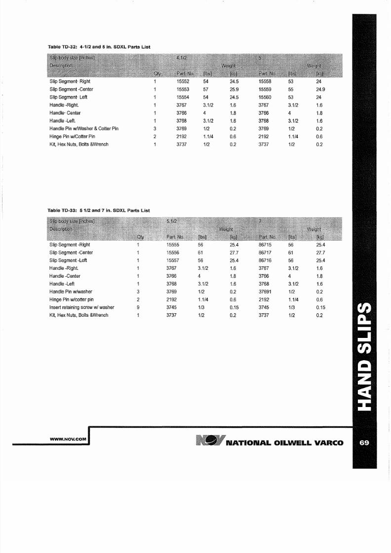
7/25/2019 Rotary Care & Maintenance Handbook
http://slidepdf.com/reader/full/rotary-care-maintenance-handbook 71/116
Table TD 32: 4 1/2 and 5 in. SDXL Parts List
Slip
Segment· Right
15552 54 24 5 15558
53
24
Slip Segment -Center 15553
57 25 9 15559
55
24 9
Slip
Segment·
Left
15554
54
24 5
15560
53
24
Handle
-Right.
3767 3 1/2
1 6
3767
3 1/2 1 6
Handle' Center 3766
4
1 8
3766
4
1 8
Handle -Left.
3768
3 1/2
1 6
3768
3 1/2
1 6
Handle
Pin
wiWasher Cotter
Pin
3
3769
1/2
0 2
3769 1/2
0 2
Hinge Pin
w/Cotter
Pin
2 2192 1 1/4
0 6
2192
1 1/4
0 6
Kit, Hex Nuts, Bolts Wrench
3737
1/2
0 2
3737
1/2 0 2
Table TD 33:
51 2
and 7 in. SDXL Parts List
Slip Segment -Right
15555
56 25 4
86715
56 25 4
Slip Segment -Center
15556
6
27 7
86717 6
27 7
Slip
Segment -Left 15557
56
25 4
86716
56 25 4
Handle -Right.
3767 3 1/2
1 6
3767
3 1/2
1 6
Handle -Center
3766 4
1 8
3766
4
1 8
Handle -Left
3768 3 1/2
1 6
3768
3 1/2
1 6
Handle
Pin w/washer
3 3769 1/2
0 2
37691
1/2
0 2
Hinge
Pin w/cotter
p n
2 2192 1 1/4
0 6
2192
1 1/4
0 6
Insert retaining screw wi
washer
9
3745 1/3
0 15
3745
1/3 0 15
Kit, Hex
Nuts,
Bolts Wrench
3737 1/2
0 2
3737
1/2 0 2
WWW NOV COM
N TION L OILWELL V RCO

7/25/2019 Rotary Care & Maintenance Handbook
http://slidepdf.com/reader/full/rotary-care-maintenance-handbook 72/116
SDHL: Rated Extra Long Rated Rotary Slips
Figure: SDHL Rated Slips w load rings
The SDHL-slips are rated for 750 Short
Tons
and are
the recommend
ed slips in applications
with
increased
drilling
depths and
on
floaters
specifically.
Table: SDHL Ordering Information
Part No.: Slip complete w/inserts
50006021-450
INSERTS
2168
Oty
45
LOAD RINGS
50006033
Oty
Part No.: Slip
complete
w/inserts
50006040-588
INSERTS
Set:
Part No 2632
Oty
60
LOAD RINGS
50006038
Oty
N TION L OILWELL V RCO
VARCO NO.3
BOWL
VARCO DRIVE
MASTER BUSHING
50006021-500 50006021-550
2169
2170
45
45
50006033
50006033
50006040-600 50006040-638
2650
2652
60 6
50006038 50006038
50006040-463 50006040-575
2521
2656
6
60
50006038 50006038
50006040-663 50006040-688
2655 2173
60 60
50006038
50006038
WWW NOV COM
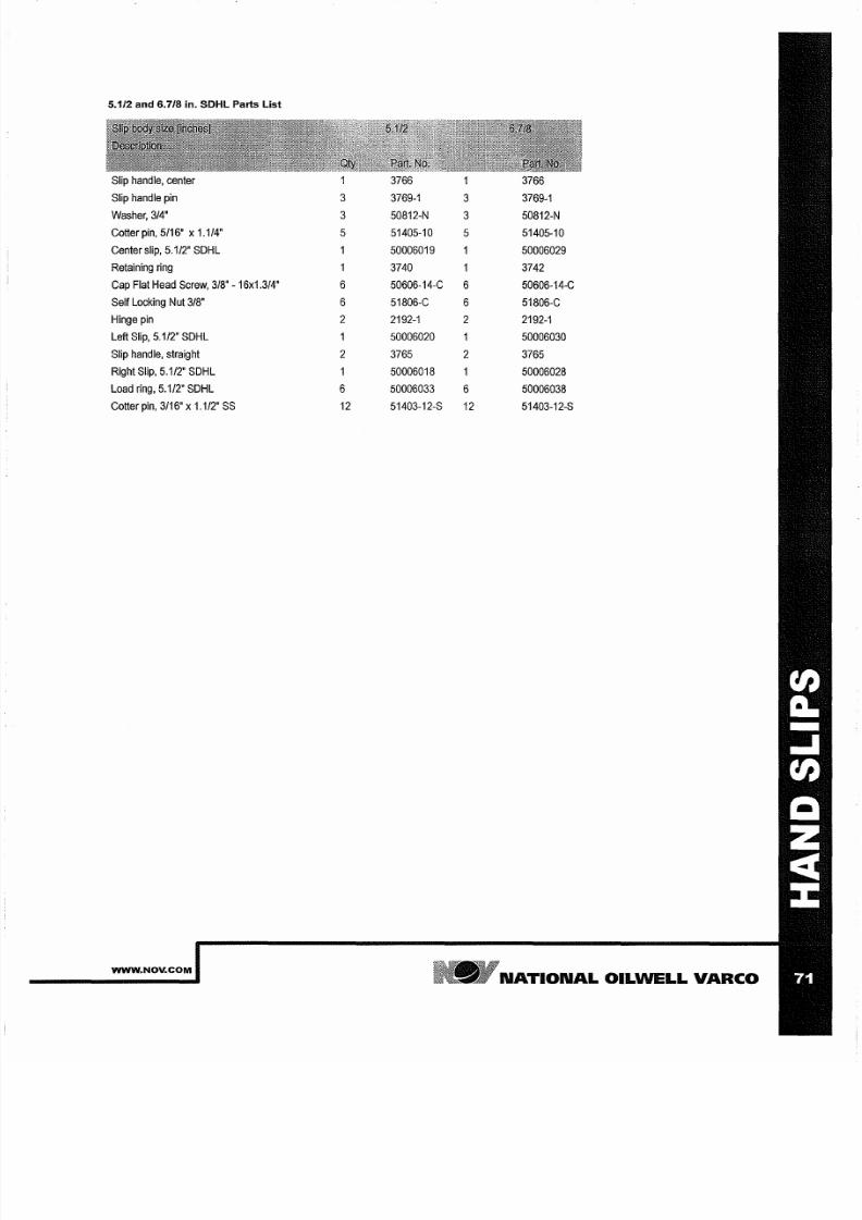
7/25/2019 Rotary Care & Maintenance Handbook
http://slidepdf.com/reader/full/rotary-care-maintenance-handbook 73/116
5 1/2 and 6 7/8 in SDHL Parts List
Slip handle, center
3766
1
3766
Slip
handle pin 3
3769-1
3 3769-1
Washer, 3/4
3
50812-N
3
50812-N
Cotter pin, 5/16'
x
1.1/4 5 51405-10
5
51405-10
Center
slip, 5.1/2
SDHL
1 50006019
50006029
Retaining
ring 3740
3742
Cap
Flat Head
Screw, 3/8
16x1.3/4
6
50606-14-C
6 50606-14-C
Self
Locking Nut
3/8'
6 51806-C
6
51806-C
Hinge
pin
2
2192-1
2
2192-1
Left Slip, 5.1/2' SDHL
50006020 1
50006030
Slip
handle, straight 2 3765
2
3765
Right
Slip,
5.1/2
SDHL
1
50006018 50006028
Load
ring,
5.1/2' SDHL
6
50006033
6 50006038
Cotter pin, 3/16
x
1.1/2' 12 51403-12-S
12 51403-12-S
WWW NOV COM
N TION L OILW LL
V RCO
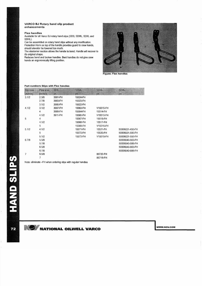
7/25/2019 Rotary Care & Maintenance Handbook
http://slidepdf.com/reader/full/rotary-care-maintenance-handbook 74/116
V RCO BJ Rotary hand slip product
enhancements
Flex handles
Available for all Varco BJ rotary hand slips (SOS,
SOML,
SOXL
and
SOHL).
Can be
assembled on rotary hand slips
without
any modification.
Protection Horn
on
top of the handle provides guard to
crew
hands,
should elevator be lowered too much.
The
elastomer
section
allows
the handle to bend.
Handle will
recover to
it s original shape.
Reduces bend and broken handles. Bent handles do not give crew
hands an
ergonomically
lifting position.
Part numbers Slips with Flex handles
3 1/2
2 3/8
3901-FH
15524-FH
2 7/8
3903-FH 15523-FH
3 112 3905-FH
15522-FH
4 1/2
3 1/2
3907-FH
15563-FH
3909-FH 15564-FH
4 1/2
3911-FH
15565-FH
5 15567-FH
4 1/2
15568-FH
5
15569-FH
5 1/2
4 1/2
15571-FH
5
15572-FH
5 1/2
15573-FH
6 7/8
5 5/8
5 7/8
6 5/8
6 7/8
7
6 5/8
7
Note: eliminate
-FH when
ordering slips with
regular
handles
V15515-FH
15514-FH
V15513-FH
15518-FH
15517-FH
V15516-FH
15521-FH
15520-FH
V15519-FH
86720-FH
86719-FH
N TION L OILWELL V RCO
50006021-450-FH
50006021-500-FH
50006021-550-FH
50006040-563-FH
50006040-588-FH
50006040-663-FH
50006040-688-FH
WWW NOV COM
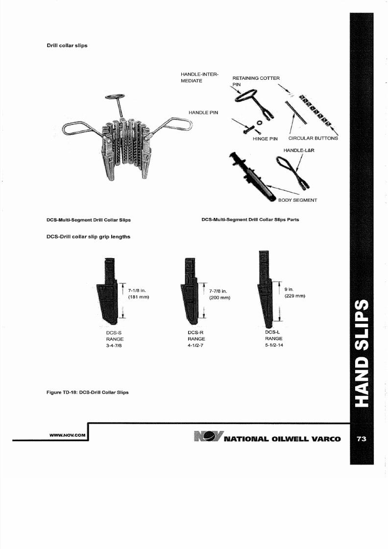
7/25/2019 Rotary Care & Maintenance Handbook
http://slidepdf.com/reader/full/rotary-care-maintenance-handbook 75/116
Drill
collar slips
DCS-Multi-Segment Drill Collar Slips
DeS-Drill
collar
Slip
grip
lengths
DCS-S
RANGE
3 4 7/8
Figure TD-18: DCS-Drill Collar Slips
WWW NOV COM
HANDLE-INTER
MEDIATE
HANDLE PIN
RETAINING
COTTER
x
\
HINGE PIN
CIRCULAR BUTTONS
DCS-Multi-Segment Drill Collar Slips Parts
DCS-R
RANGE
4 1/2 7
7 7/8
in.
200 mm
DCS-L
RANGE
5 1/2 14
9
in
229
mm
N TION L
OIL
WELL V RCO
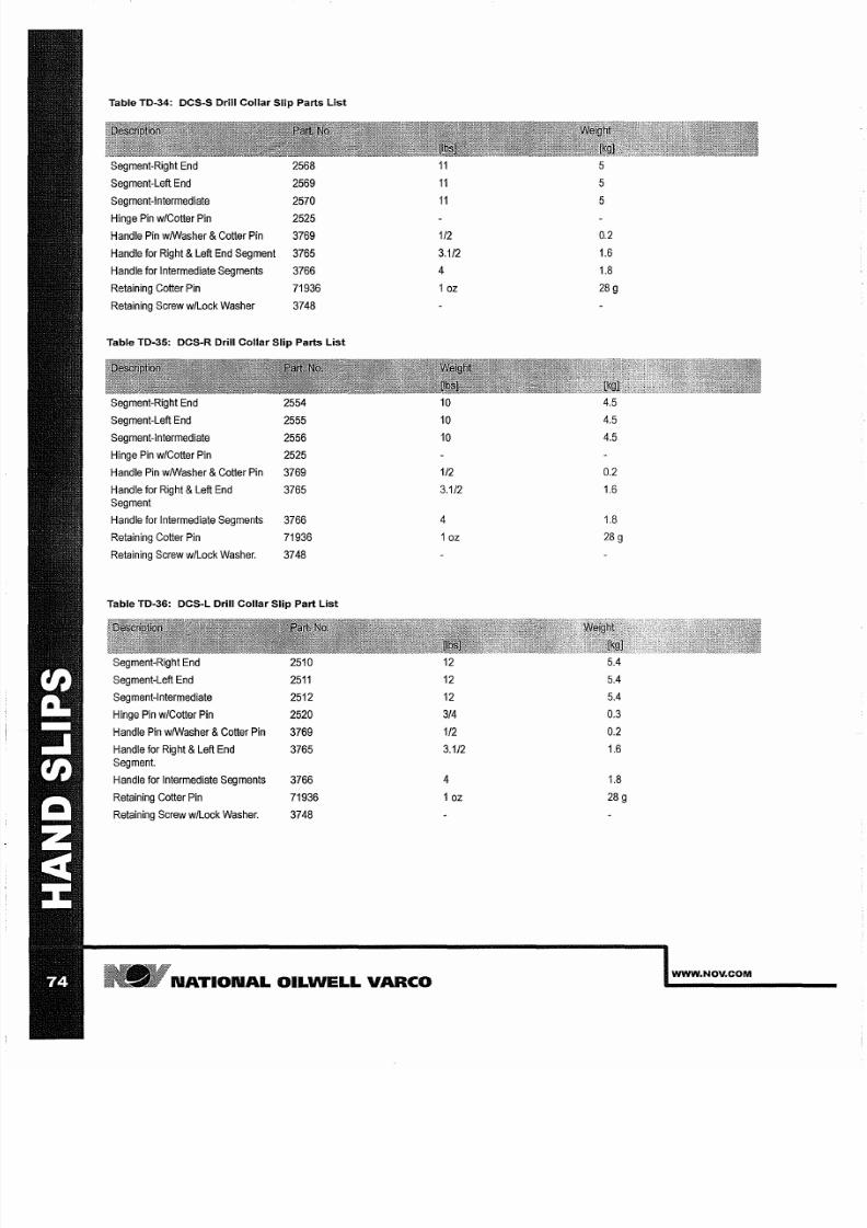
7/25/2019 Rotary Care & Maintenance Handbook
http://slidepdf.com/reader/full/rotary-care-maintenance-handbook 76/116
Table TD 34: DCS S Drill Collar Slip Parts List
Segment Right
End
2568
5
Segment Left End
2569
5
Segment Intermediate
2570
5
Hinge
Pin w/Cotter
Pin
2525
Handle Pin wIWasher Cotter Pin
3769
1/2
0.2
Handle for Right Left
End
Segment
3765
3 1/2
1.6
Handle
for
Intermediate
Segments
3766
4 1.8
Retaining Cotter Pin
71936
10z
28
g
Retaining
Screw
w/Lock
Washer 3748
Table TD 3S: DCS R Drill Collar Slip Parts List
Segment Right
End
2554
10
4.5
Segment Left
End
2555
10
4.5
Segment Intermediate
2556
10
4.5
Hinge Pin
w/Cotter
Pin
2525
Handle
Pin
wIWasher Cotter Pin
3769
1/2
0.2
Handle for Right Left End
3765
3 1/2
1.6
Segment
Handle for Intermediate Segments
3766
4
1.8
Retaining Cotter Pin 71936
10z
28
g
Retaining Screw
w/Lock Washer.
3748
Table TD 36: DCS L Drill Collar Slip Part List
Segment Right
End 2510
12
5.4
Segment Left End
25
12 5.4
Segment Intermediate
2512
12 5.4
Hinge Pin w/Cotter
Pin
2520
3/4
0.3
Handle
Pin wIWasher
Cotter
Pin
3769
1/2
0.2
Handle for
Right
Left
End
3765
3 1/2
1.6
Segment.
Handle
for Intermediate Segments
3766
4
1.8
Retaining
Cotter
Pin
71936
10z
28
g
Retaining Screw w/Lock Washer.
3748
N TION L OILWELL V RCO
WWW NOV COM
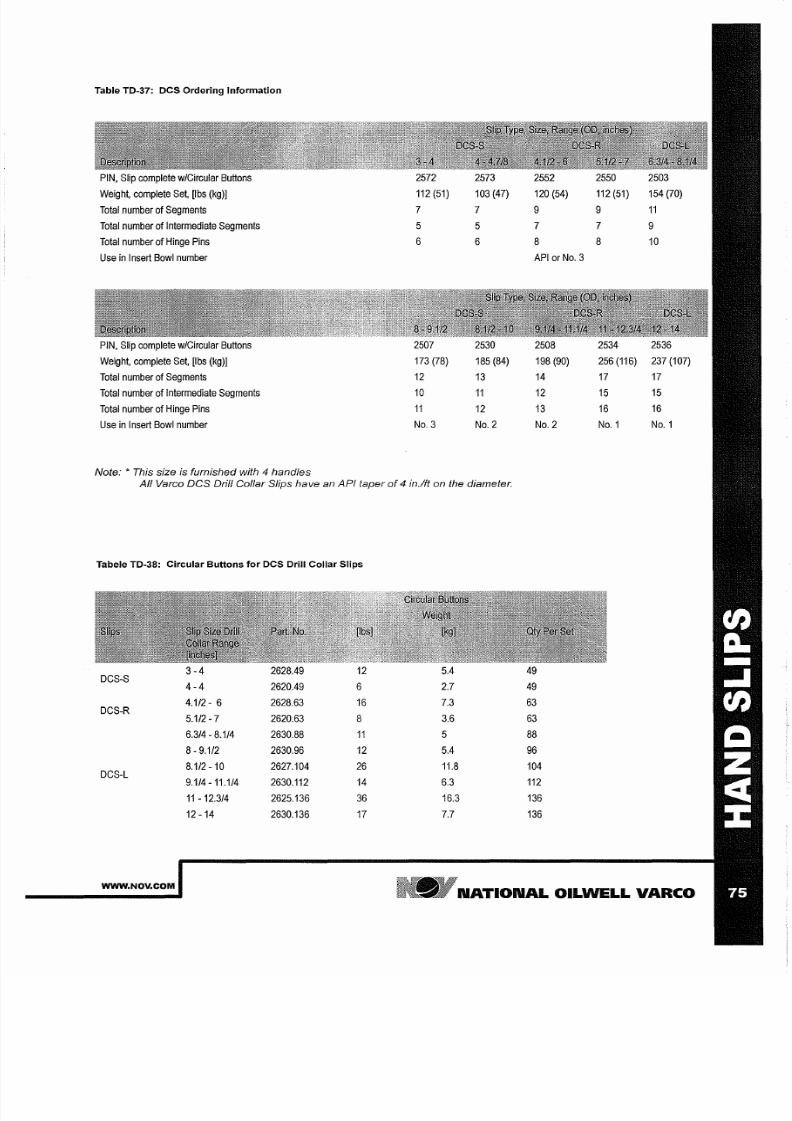
7/25/2019 Rotary Care & Maintenance Handbook
http://slidepdf.com/reader/full/rotary-care-maintenance-handbook 77/116
Table TD 37: DCS Ordering Information
PIN, Slip complete w/Circular
Buttons
Weight,
complete
Set, [Ibs kg)]
Total number
of
Segments
7
7 9 9
11
Total number
of
Intermediate
Segments 5
5
7 7
9
Total
number
of Hinge Pins 6
6 8
8 10
Use in
Insert
Bowl number
API
or No 3
PIN,
Slip complete w/Circular
Buttons
Weight,
complete
Set, [Ibs kg)]
Total
number
of
Segments
12
13
14 17
17
Total number of
Intermediate
Segments
10
11
12
15 15
Total number of Hinge
Pins
11
12 13 16
16
Use
in
Insert
Bowl
number
No.3
No.2
No.2
No.1 No.1
Note: This size is furnished with handles
ll Varco DCS Drill Collar Slips have an API taper
of
in.lft on the diameter.
Tabele TD 3S: Circular Buttons for DCS Drill Collar Slips
3 4
2628.49
12
5.4
49
DCS-S
4 4
2620.49
6
2.7
49
4.1/2
-
6
2628.63
16
7.3
63
DCS-R
5.1/2 7
2620.63 8 3.6 63
6.3/4 -8.1/4 2630.88 11 5 88
8 9.1/2
2630.96 12 5.4
96
8.1/2
10
2627.104
26 11.8 104
DCS-L
9.1/4 11.1/4 2630.112
14
6.3 112
11 12.3/4 2625.136 36
16.3
136
12
-14 2630.136
17
7.7
136
WWW NOV COM
N TION L OILWELL V RCO
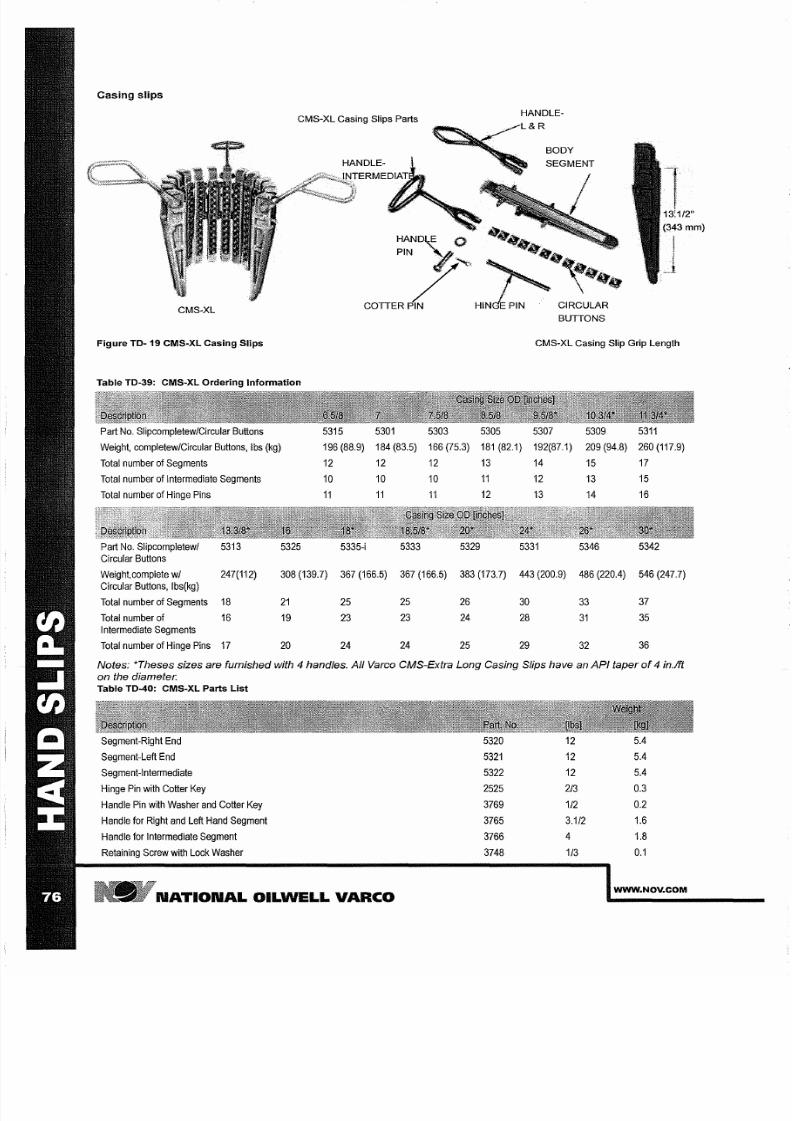
7/25/2019 Rotary Care & Maintenance Handbook
http://slidepdf.com/reader/full/rotary-care-maintenance-handbook 78/116
Casing slips
CMS-XL Casing Slips Parts
eMS XL
Figure TO- 19 CMS-XL Casing S lips
Table TO-39: CMS-XL Ordering Information
Part No.
Slipcompletew/Circular
Buttons
5315
5301
5303
Weight, completew/Circular Buttons, Ibs kg) 196 88.9) 184 83.5) 166 75.3)
Total number of Segments 12
12
12
Total
number of Intermediate
Segments
10 10 10
Total number
of Hinge Pins
11
11
11
Part No.
Slipcompletewl
5313
5325
5335-i
5333 5329
Circular
Buttons
HANDLE-
BODY
3:1/2
343 mm)
I
)
-
1
CMS-XL Casing Slip Grip Length
5305 5307
5309
5311
181 82.1)
192 87.1)
209 94.8) 260 117.9)
13
14
15 17
11
12
13
15
12 13
14
16
5331
5346 5342
Weight,complete
w
247 112)
308
139.7)
367 166.5) 367 166.5) 383 173.7)
443
200.9) 486 220.4) 546
247.7)
Circular Buttons,
Ibs kg)
Total
number of
Segments 18
21 25
25 26
30 33
37
Total number of
16
19
23
23
24
28
31
35
Intermediate
Segments
Total
number
of
Hinge
Pins 17 20 24
24 25
29 32
36
Notes: *Theses sizes are furnished with
4
handles.
ll
Varco CMS-Extra Long Casing Slips have an
PI
taper of
4
in 1ft
on the diameter.
Table TD-40: CMS-XL Parts
List
Segment-Right End 5320
12 5.4
Segment-Left End 5321
12
5.4
Segment-Intermediate 5322
12 5.4
Hinge Pin
with
Cotter Key 2525 2/3
0.3
Handle
Pin with Washer and Cotter
Key
3769
1/2 0.2
Handle for
Right and Left Hand
Segment
3765
3 1/2
1.6
Handle for Intermediate Segment 3766
4 1.8
Retaining Screw with
Lock
Washer
3748 1/3 0 1
N TION L OILWELL V RCO
WWW NOV COM
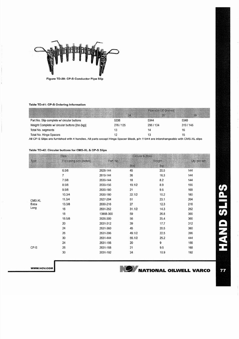
7/25/2019 Rotary Care & Maintenance Handbook
http://slidepdf.com/reader/full/rotary-care-maintenance-handbook 79/116
Figure TO-20: CpoS onductor Pipe Slip
Table T0-41: CP-S Ordering Information
Part
No.
Slip complete w circular
buttons
5338 5344 5340
Weight
Complete w circular buttons [Ibs kg)]
276/125 296/134
319/145
Total
No. segments
13 14 16
Total
No.
Hinge Spacers
12 13 15
All CpoS Slips are fumished with 4 handles. All parts except Hinge Spacer Block, pIn 11944 are interchangeable with CMS-XL slips
Table T0-42: Circular but tons for CMS-XL cpoS Slips
6 5/8
2628 144 45 20.5 144
2619 144
36
16.3 144
7 5/8 2630 144 18
8.2 144
8 5/8
2630 156
19 1/2 8.9 156
9 518
2630 180
2 9.5
168
10 3/4 2630 180
22 1/2
10.2
180
CMS-XL
11 3/4
2627 204
5 23.1
204
Extra
13 3/8
2630 216
27
12.3
216
Long
16
2631 252
31 1/2
14.3
252
18
13868 300
59
26.8 300
18 5/8
2626 300
56
25.4
300
20 2631 312
39 17.7 312
24
2631 360
45
20.5 360
26
2631 396
49 1/2
22.5
396
30 2631 444 55 1/2 25.2 444
24
2631 156
20
9 156
CpoS
26 2631 168
2 9.5
168
30 2631 192
24
10.9 192
WWW NOV COM
N TION L
OILWELL
V RCO
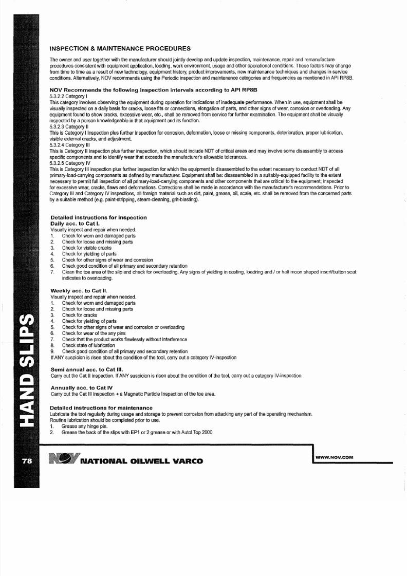
7/25/2019 Rotary Care & Maintenance Handbook
http://slidepdf.com/reader/full/rotary-care-maintenance-handbook 80/116
INSPECTION MAINTENANCE PROCEDURES
The owner and user together with the manufacturer should
jointly
develop and update inspection, maintenance,
repair
and remanufacture
procedures consistent with equipment application, loading, work environment, usage
and
other
operational conditions.
These factors
may
change
from time to time as a result of new technology, equipment history,
product
improvements, new maintenance
techniques
and changes in service
conditions. Alternatively,
NOV recommends
using the Periodic
inspection
and
maintenance
categories and frequencies
as
mentioned
in
API
RP8B.
NOV Recommends the following inspection intervals according to API RP8B
5.3.2.2 Category
I
This category involves
observing
the equipment
during
operation for
indications of
inadequate
performance.
When in
use, equipment
shall be
visually inspected on adaily
basis
for cracks, loose
fits
or connections, elongation of
parts,
and other signs of
wear,
corrosion or overloading. Any
equipment
found to
show
cracks,
excessive wear,
etc., shall be
removed
from
service
for further
examination.
The equipment shall be
visually
inspected
by a
person
knowledgeable
in
that
equipment
and its function.
5.3.2.3 Category II
This
is
Category
I nspection plus further inspection
for
corrosion, deformation, loose or missing components, deterioration, proper lubrication,
visible external
cracks, and adjustment.
5.3.2.4 Category III
This
is
Category
II inspection plus
further
inspection,
which should include NDT of critical areas and may involve some
disassembly
to
access
specifiC components and to
identify wear that exceeds the manufacturer s allowable tolerances.
5.3.2.5 Category
IV
This
is
Category III inspection plus further
inspection
for which the equipment
is
disassembled
to the extent necessary to
conduct
NDT of all
primary-load-carrying
components
as
defined
by
manufacturer. Equipment
shall
be:
disassembled
in
a
suitably-equipped facility
to
the
extent
necessary
to
permit full inspection
of all
primary-load-carrying
components and
other
components that
are critical
to
the equipment;
inspected
for excessive wear, cracks, flaws and deformations. Corrections shall be made in accordance with the manufacturer s recommendations. Prior to
Category
III and
Category
IV
inspections,
all foreign
material
such as
dirt, paint,
grease,
oil,
scale,
etc. shall
be
removed from
the concerned
parts
by a
suitable
method (e.g.
paint-stripping, steam-cleaning, grit-blasting).
Detailed instructions for inspection
Daily acc to Cat I
Visually inspect
and
repair
when needed.
1
Check for worn
and damaged
parts
2 Check for loose
and
missing parts
3
Check
for visible
cracks
4.
Check for yielding of parts
5 Check for other
signs
of wear and
corrosion
6
Check good condition
of
all
primary
and
secondary
retention
7
Clean the
toe
area
of the
slip and check
for
overloading.
Any signs
of
yielding in casting, load ring and
or half
moon
shaped insert/button
seat
indicates
to
overloading.
Weekly acc to Cat II
Visually
inspect and repair when needed.
1 Check
for
worn and damaged
parts
2 Check for loose
and
missing parts
3 Check for
cracks
4. Check for
yielding of
parts
5 Check for other signs of wear and corrosion or overloading
6 Check for wear of the any pins
7. Check that
the product
works
flawlessly
without
interference
8
Check state
of
lubrication
9 Check good condition of all
primary
and secondary retention
If
ANY suspicion is
risen about
the condition
of the
tool, carry out
acategory
IV-inspection
Semi annual acc to Cat III
Carry out
the Cat
II inspection.
If ANY
suspicion
is risen about the condition
of
the tool,
carry
out acategory
IV-inspection
Annually acc to at IV
Carry
out the
Cat
III
inspection
a
Magnetic
Particle
Inspection of
the toe area.
Detailed instructions
for
maintenance
Lubricate the tool regularly during usage and storage to prevent corrosion from attacking any part
of
the operating mechanism.
Routine
lubrication should
be
completed prior to use.
1. Grease
any
hinge pin.
2
Grease the
back of the
slips with
EP1
or 2grease or with
Autol Top
2000
N TION L OILWELL VARCO
WWW NOV COM

7/25/2019 Rotary Care & Maintenance Handbook
http://slidepdf.com/reader/full/rotary-care-maintenance-handbook 81/116
FETYCL MPS
WWW NOV COM
NATIONAL OILWELL VARCO

7/25/2019 Rotary Care & Maintenance Handbook
http://slidepdf.com/reader/full/rotary-care-maintenance-handbook 82/116
N TION L OILWELL V RCO
WWW NOV COM
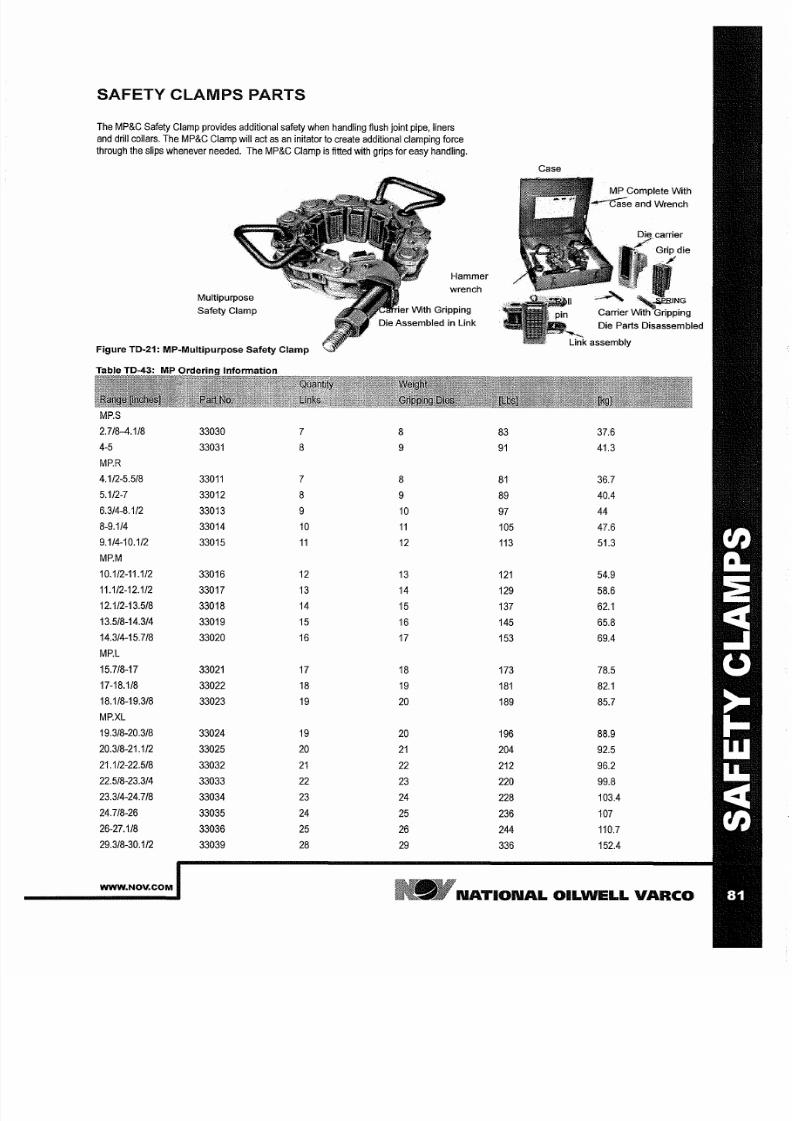
7/25/2019 Rotary Care & Maintenance Handbook
http://slidepdf.com/reader/full/rotary-care-maintenance-handbook 83/116
SAFETY CLAMPS PARTS
The
MP C
Safety Clamp provides additional safety when handling flush joint
pipe,
liners
and
drill
collars. The MP C Clamp will act as n initator to create additional clamping force
through the slips
whenever
needed. The MP C Clamp is
fitted with
grips
for easy
handling.
Multipurpose
Safety Clamp
Figure TO 21: MP Multipurpose Safety Clamp
MP.S
2.7/8 4.1/8
33030
4 5
33031
8
MP.R
4.1/2 5.5/8
33011
5.1/2 7
33012
8
6.3/4 8.112
33013
9
8 9.1/4
33014
10
9.1/4 10.1/2
33015
11
MP.M
10.1/2 11.1/2
33016
12
11.1/2 12.1/2
33017
13
12.1/2 13.5/8
33018
14
13.5/8 14.3/4
33019
15
14.3/4 15.7/8
33020
16
MP.L
15.7/8 17
33021 17
17 18.1/8
33022
18
18.1/8 19.3/8
33023
19
MP.XL
19.3/8 20.3/8
33024
19
20.3/8 21.1/2
33025
20
21.1/2 22.5/8
33032
21
22.5/8 23.3/4
33033
22
23.3/4 24.7/8
33034
23
24.7/8 26
33035
24
26 27.1/8
33036
25
29.3/8 30.1/2
33039
28
8
9
8
9
10
11
12
13
14
15
16
17
18
19
20
20
21
22
23
24
25
26
29
Hammer
wrench
Case
83 37.6
91
41.3
81
36.7
89
40.4
97
44
105
47.6
113
51.3
121
54.9
129
58.6
137 62 1
145
65.8
153
69.4
173
78.5
181
82 1
189 85.7
196
88.9
204
92.5
212
96.2
220
99.8
228
103.4
236
107
244 110.7
336
152.4
WWW NOV COM
N TION L
OILWELL VARCO
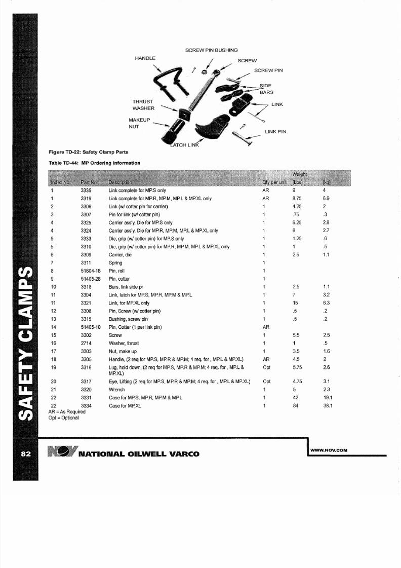
7/25/2019 Rotary Care & Maintenance Handbook
http://slidepdf.com/reader/full/rotary-care-maintenance-handbook 84/116
S REW PIN BUSHING
HANDLE
S REW
S REW
PIN
T R U S T ~
LINK
NUT
LINK PIN
Figure TD 22: Safety Clamp Parts
Table TD 44: MP Ordering Information
3335
Link
complete
for MP.S only AR
9 4
1
3319 Link complete
for MP.R, MP.M, MP.L MP.XL only
AR
8.75
6.9
2
3306 Link
wI cotler pin for
carrier)
1
4.25
2
3
3307
Pin for link wI cotler pin) .75 3
4
3325 Carrier
ass y, Die
for
MP.S only
6.25 2.8
4
3324
Carrier
ass y,
Die for
MP.R,
MP.M,
MP.L
MP.XL
only 6
2.7
5
3333
Die, grip
wI cotler pin)
for
MP.S only
1.25
.6
5
3310 Die, grip wI
cotler
pin) for MP.R,
MP.M,
MP.L MP.XL
only
1 .5
6
3309
Carrier, die
2.5
1.1
7
3311
Spring
8
51604-18 Pin, roll
9 51405-28 Pin, cotler
10 3318
Bars,
link
side pr 2.5
1.1
11
3304 Link, latch for
MP.S,
MP.R, MP.M MP.L
7
3.2
11 3321
Link,
for
MP.xL
only
15 6.3
12 3308
Pin, Screw wI cotler
pin)
.5
.2
13 3315 Bushing, screw pin
.5
.2
14 51405-10 Pin, Cotler 1
per link pin)
AR
15 3302 Screw
5.5 2.5
16
2714
Washer,
thrust
1 .5
17 3303
Nut,
make
up
3.5
1.6
18
3305
Handle, (2 req for
MP.S, MP.R MP.M; 4
req. for, MP.L MP.xL) AR 4.5
2
19
3316
Lug, hold down,
(2 req
for
MP.S, MP.R
MP.M;
4
req. for, MP.L Opt 5.75 2.6
MP.XL)
20
3317
Eye, Lifting
(2
req for MP.S, MP.R
MP.M; 4 req.
for,
MP.L MP.XL)
Opt 4.75
3.1
21 3320 Wrench
1 5
2.3
22 3331 Case for
MP.S, MP.R,
MP.M
MP.L
42
19.1
22
3334 Case
for MP.xL
84
38.1
AR
s
Required
Opt Optional
NATIONAL OILWELL VARCO
WWW NOV COM
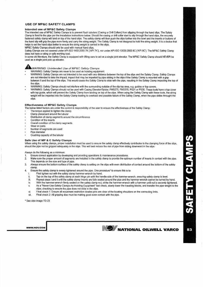
7/25/2019 Rotary Care & Maintenance Handbook
http://slidepdf.com/reader/full/rotary-care-maintenance-handbook 85/116
USE OF MP C SAFETY CLAMPS
Intended use
of
MP C Safety Clamps
The
intended
use
of
MP&C
Safety
Clamps is
to
prevent flush tubulars (Casing or
Drill
Collars) from slipping through
the hand
slips.
The
Safety
Clamp is fixed to the pipe per the installation instructions below. Should the casing or drill collar start to
slip
through the
hand
slips, the securely
fastened safety clamp
will land on top
of
the hand slips. The safety clamp will then push the slips further into the bowl and the
inserts
or buttons of
the
hand
slip
will
grip
the
pipe more firmly
and carry the
string
weight.
The Safety Clamp
is
not
designed to
hold
the
string
weight. It is a
device that
helps
to
set
the hand
slips better
to
ensure the string
weight
is carried
in
the slips.
MP&C Safety
Clamps
should only be used with manual hand
slips.
Safety
Clamps are not covered under API-ISO
1493:2003
7K (,API 7K'),
nor under
API-ISO 13535:2000 BC
(,API
BC'). The
MP&C
Safety Clamp
does
not
have a rating or safe working load.
In
some
old literature, the Safety Clamp
is
equipped
with
lifting ears to
act
as a
single
joint elevator.
The MP&C
Safety Clamp should NEVER be
used as a
single
joint pick up elevator.
AWARNING
Unintended Use of MP C Safety Clamps
WARNING: Safety Clamps are never
to
be used
as hoisting equipment.
WARNING: Safety Clamps are not intended
to
be
used
with any distance between the top
of
the slips
and
the Safety Clamp. Safety Clamps
are not
intended
to take the impact,
impact that
may be imparted by pipe
sliding
in
the slips
if
the Safety Clamp
is
mounted with agap
between it and the top of the slips. This would cause the Safety Clamp to
slide
with the pipe, resulting in
the
Safety
Clamp
impacting the
top
of
the slips.
WARNING:
Safety
Clamps should not
interfere with
the
surrounding
outside
of
the
slip
top area, e.g.
guides
or top covers.
WARNING:
Safety
Clamps
should not be
used
with Casing
ElevatorlSpider, FMS275, FMS375,
PS21 or
PS30.
These
tools
have a op
cover
with
top
guide, which will prevent the Safety Clamp from landing
on
top
of
the slips. When using
the
Safety Clamp with
these
tools,
the
string
weight will be imparted
into
the Safety Clamp leading to overload and possible failure of the Safety Clamp, when the pipe slides throught the
slips.
Effectiveness
of
MP C Safety Clamps
The
below
listed factors
are under
the control responsibility
of
the user
to ensure the effectiveness of the Safety
Clamp:
The torque applied to tighten the clamp.
Clamp
placement
around the
tubular
Distribution
of clamp segments
around
the
circumference
Condition of the inserts
Overall
condition
of the
clamp
segments
Wear on parts
Number of segments are used
Pipe
diameter
Crushing capacity
of
the tubular
Safe Use
of
P C Safety Clamps
When using
the
safety clamps, proper installation must
be
used to
ensure
the safety clamp effectively
contributes
to the clamping force
of
the slips,
should
the pipe not be
gripped
adequately
in
the slips. This will best reduce the risk of pipe
from
sliding downward
in
the
slips:
Always do
the
following
as
aminimum:
1
Ensure correct
application
by developing and providing operations maintenance procedures.
2 Make sure the
proper
amount of segments are installed in the safety clamp to provide the optimum
number
of
inserts
in
contact
with the pipe.
This depends on the size
and
type of
pipe.
3 Always ensure the bottom
surface
of the safety clamp is setting on the slips
with
even
distribution
of contact
around
the bottom of the safety
clamp.
4. Ensure the safety
clamp
is evenly
tightened around the pipe.
One procedure' to ensure this is to:
i First tighten nut
with
the safety clamp
hammer-wrench
by hand.
ii.
Tap
on
the
top
of
the
safety
clamp
at
each hinge
pin
with the handle side
of
the
hammer-wrench, ensuring
safety
clamp
is
level.
iii.
Repeat steps
i and ii
until
the
safety
clamp
inserts are fully
seated
around the pipe
and
the
hammer-wrench
cannot
be turned by hand.
iv With the hammer-wrench finnly seated on the safety clamp nut, strike the hammer-wrench
with
ahammer until nut
is
securely tightened.
v As a Never-Use-Safety-Clamps-As-Hoisting-Equipment last check,
slowly
lower the traveling blocks, and transfer the pipe weight to the
slips; checking
to ensure
the pipe does not slide in the
slips.
vi.
Final check
1:
Ensure all movement restriction dowles pins are clear
of
the locating shoulders on the connecting links.
vii. Final
check
2: All gripping dies
must
be making good even contact
with
the pipe.
, See also image TD-23
WWW NOV COM
N TION L OILWELL V RCO
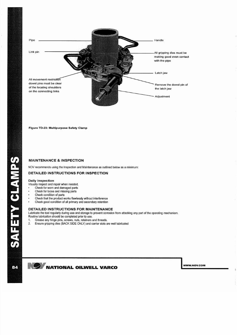
7/25/2019 Rotary Care & Maintenance Handbook
http://slidepdf.com/reader/full/rotary-care-maintenance-handbook 86/116
Pipe
Link pin
All movement
n trir.ttnn
dowel pins must be clear
of the locating shoulders
on the connecting links
Figure TD 23:
ultipurpose
Safety Clamp
M INTEN NCE INSPECTION
Handle
-\II
gripping dies must be
making good even contact
with the pipe
Latch
jaw
Remove the dowel pin of
the latch jaw
Adjustment
NOV recommends
using the Inspection
and Maintenance as
outlined below
as a minimum:
DET ILED INSTRUCTIONS FOR INSPECTION
Daily inspection
Visually inspect
and
repair
when needed.
Check for worn and
damaged
parts
Check
for
loose and missing parts
Check
condition
of
parts
Check
that the product works flawlessly without interference
Check good condition
of
all primary and secondary retention
DET ILED INSTRUCTIONS FOR M INTEN NCE
Lubricate
the
tool regularly during use and storage
to
prevent corrosion from attacking any part
of the
operating mechanism.
Routine lubrication should
be
completed
prior to use.
1. Grease any hinge
pins,
screws, nuts, retainers and
threads.
2
Ensure gripping dies BACK SIDE
ONLY)
and carrier slots are well lubricated
N TION L OILWELL V RCO
WWW_NOV COM
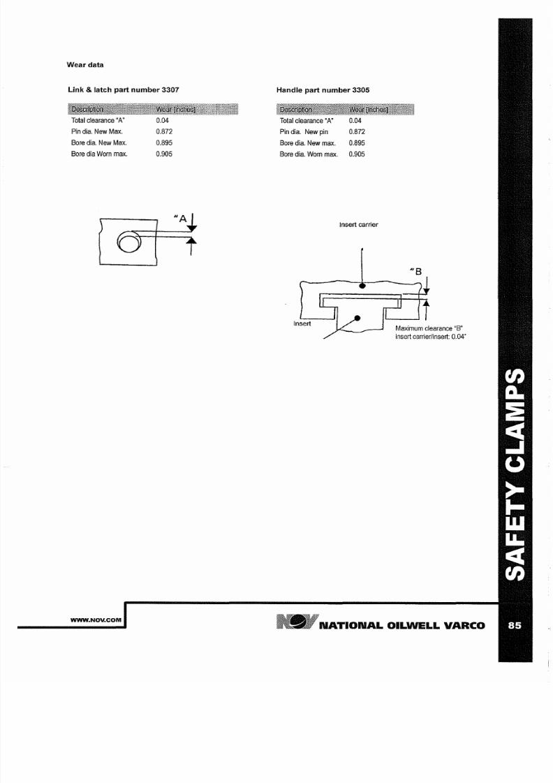
7/25/2019 Rotary Care & Maintenance Handbook
http://slidepdf.com/reader/full/rotary-care-maintenance-handbook 87/116
Wear data
Link latch part number 3307
Total
clearance
A
Pin dia. New Max.
Bore
dia. New Max.
Bore dia Worn rnax.
WWW NOV COM
0.04
0.872
0.895
0.905
Handle part number 3305
Total
clearance A'
0.04
Pin dia. New pin 0.872
Bore dia. New rnax.
0.895
Bore dia. Worn rnax. 0.905
Insert
carrier
Insert
8
Maxirnurn clearance B
insert carrier/insert: 0.04
N TION L OILWELL V RCO
7/25/2019 Rotary Care & Maintenance Handbook
http://slidepdf.com/reader/full/rotary-care-maintenance-handbook 88/116
N TION L OILWELL V RCO
WWW NOV COM
7/25/2019 Rotary Care & Maintenance Handbook
http://slidepdf.com/reader/full/rotary-care-maintenance-handbook 89/116
LI TING GE R SLINGS
WWW NOV COM
NATIONAL OILWELL VARCO

7/25/2019 Rotary Care & Maintenance Handbook
http://slidepdf.com/reader/full/rotary-care-maintenance-handbook 90/116
N TION L OILWELL V RCO
WWW NOV COM
7/25/2019 Rotary Care & Maintenance Handbook
http://slidepdf.com/reader/full/rotary-care-maintenance-handbook 91/116
LIFTING GEAR SLINGS
Maintenance inspection
The owner and user together
with
the manufacturer should
jointly
develop
and
update inspection, maintenance, repair and remanufacture procedures
consistent with equipment
application,
loading, work
environment,
usage and other
operational conditions.
These
factors
may change from time to time
as
a
result of
new technology,
equipment
history,
product improvements,
new maintenance
techniques
and
changes
in
service
conditions.
Alternatively,
NOV recommends
using
the
Periodic inspection and maintenance
Categories
and Frequencies
as mentioned in API RP8B
Table
1.
NOV
Recommends the following inspection intervals according
to
API RP88
5.3.2.2 Category
I
This category involves observing the equipment during operation for indications
of
inadequate performance.
When
in use, equipment shall be visually
inspected
on adaily basis for cracks, loose
fits
or connections, elongation of parts,
and
other signs
of
wear, corrosion or overloading. Any equipment
found to show cracks, excessive wear,
etc., shall be
removed from
service
for further examination. The
equipment
shall be
visually
inspected by a
person knowledgeable
in
that equipment
and its
function.
5.3.2.3 Category
II
This is
Category
I
nspection plus
further
inspection for corrosion,
deformation, loose or missing components,
deterioration, proper lubrication, visible
external
cracks,
and
adjustment.
5.3.2.4 Category III
This
is
Category
II inspection
plus further inspection, which should include NOT of critical areas and may involve some
disassembly
to access specific
components and to
identify wear
that exceeds the
manufacturer s
allowable tolerances.
5.3.2.5 Category
IV
This
is
Category
III
inspection
plus further
inspection
for which the eqUipment
is
disassembled
to the extent necessary to
conduct
NDT of all
primary
load-carrying
components as defined by manufacturer.
Equipment shall
be: disassembled in a
suitably-equipped
facility to the
extent
necessary to
permit full inspection of all primary-Ioad-carrying
components and
other components that are critical
to
the equipment; inspected for excessive wear,
cracks, flaws and
deformations. Corrections
shall be made in accordance
with
the
manufacturer s
recommendations. Prior to Category III and
Category
IV
inspections,
all foreign
material
such as dirt,
paint, grease, oil,
scale, etc.
shall
be
removed
from the concerned parts by a
suitable method (e.g. paint
stripping, steam-cleaning, grit-blasting).
Detailed instructions
or
inspection
Weekly acc.
to
Cat II
Visually
inspect and repair
when
needed.
Check for
worn
and damaged parts
Check
for loose
and
missing parts
Check condition of
shackles
and or hooks
Check condition
of
springs when
present
Check for
wear
of the
any pins
Check that the product works flawlessly without interference
Check state
of lubrication
Check
for
any
visible cracks
Check good condition of all primary
and
secondary retention
IfANY
suspicion is
risen
about
the
condition
of the tool,
carry out
acategory IV-inspection
Semi annual acc. to Cat III
Carry out
the Cat II
inspection.
If ANY
suspicion
is risen
about
the condition of the tool, carry
out
a
category
IV-inspection
Annually acc. to Cat
IV
Canry
out
the Cat
III
inspection
+
a
ull Magnetic Particle
I
nspection
of
all
primary
load
bearing load components:
Hooks
Chains
Cables
Beams
see Critical Area Drawings,
when no
Critical area drawing
is
available, the complete part is considered critical
Detailed instructions
or
maintenance
Lubricate
the tool
regularly
during usage and storage to prevent
corrosion
from attacking any part of the
operating
mechanism.
Routine lubrication should be completed
prior
to use.
1 Grease
any hinge, latch
and
lock pins.
2 Grease
any grease nipples.
3 Grease any springs.
4
Grease retainers
asteners.
WWW NOV COM
NATIONAL OILWELL VARCO

7/25/2019 Rotary Care & Maintenance Handbook
http://slidepdf.com/reader/full/rotary-care-maintenance-handbook 92/116
LIFTING
GE R SLINGS
The lifting gear and lifting
slings
needs
to
be
treated according to
ISO
13535:2000 8C Lifting
equipment .
AWARNING
he
lifting gear and slings in this chapter are loadtested and
certified. Replacing
o
oad carrying parts voids the certification. In order
to
obtain
new certification pis. contact an authorized NOV repair facility.
QUICK REFERENCE LIFTING GEAR ND SLINGS
MBH1250 + all Master Bushings 50001110'
4
Way
Lifting
Sling Chain Design
Casing Bushings
50001120
2Way
Lifting Sling Chain Design
MBH1250 + all Master Bushings 50001140**
4Way
Lifting Sling
Cable Design
Casing Bushings 50001150
2
Way
Lifting
Sling Cable Design
Bowl
#1,2,3
lifter
50001130
2Way
Lifting Sling
Chain
Design
Bowl
#1,2,3 lifter
50001160
2
Way
Lifting Sling Cable Design
MSPC
Bowl lifter 1021
2
way Lifting Sling Chain Design
MPCH
Master
Bushing lifter 6699
4
way Lifting Sling Chain Design
***FMS275
59000300
2
way
lifting
sling
***FMS375
200982-1
4
way lifting sling
PS16
50004848
4
way lifting sling
'PS21
200982-1
4
way
lifting
sling
***PS21
slips
50004551
2
way lifting sling
'PS21 insert carriers 50004600-1
1
way
lifting
sling Pogo Stick
'PS21 hand
slip
bowl 50004550-21
Hand slip
bowl removal tool
***PS30
200982-1
4
way
lifting
sling
'**PS30 slips
50004551
2
way lifting sling
'PS30
insert carriers 50004600-1
1
way
lifting
sling Pogo Stick
'PS30 hand
slip bowl 50004550-30
Hand
slip
bowl removal
tool
'SJL-SPL
34568-5
Swivel
suspension
• 50001110 also as alternative for 50001120
** 50001140 also as alternative for 50001150
***
See
dedicated User Manual for details
N TION L OILWELL V RCO
WWW NOV COM
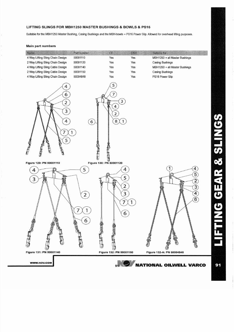
7/25/2019 Rotary Care & Maintenance Handbook
http://slidepdf.com/reader/full/rotary-care-maintenance-handbook 93/116
LIFTING SLINGS FOR MBH1250 MASTER BUSHINGS BOWLS PS16
Suitable
for the MBH1250
Master
Bushing Casing
Bushings
and the MBH-bowls
PS16
Power Slip. Allowed for overhead lifting purposes.
Main part numbers
4
Way Lifting
Sling
Chain Design
2
Way
Lifting
Sling Chain Design
4
Way Lifting Sling Cable Design
2Way
Lifting
Sling Cable Design
4
Way
Lifting
Sling Chain Design
Figure 129: PN 50001110
Figure 131: PN 50001140
WWW NOV COM
50001110
50001120
50001140
50001150
50004848
Yes Yes MBH1250 all
Master
Bushings
Yes
Yes Casing Bushings
Yes
Yes MBH1250
all
Master
Bushings
es Yes Casing Bushings
Yes
Yes PS16 Power Slip
Figure 130:
P
50001120
Figure 132: PN 50001150 Figure 132-A: PN 50004848
NATIONAL OILWELL VARCO
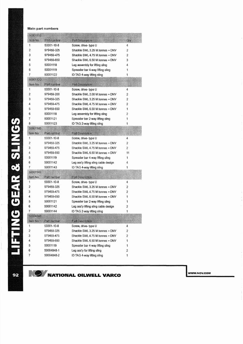
7/25/2019 Rotary Care & Maintenance Handbook
http://slidepdf.com/reader/full/rotary-care-maintenance-handbook 94/116
Main
p rt
numbers
53301-10-8
Screw,
drive-
type U
4
2
979459-325
Shackle SWL 3.25 M.tonnes DNV 2
3 979459-475
Shackle SWL 4.75 M.tonnes DNV
2
4
979459-650
Shackle
SWL 6.50
M.tonnes
DNV
3
5 50001118
Leg assembly for lifting sling 4
6 50001119
Spreader
bar
4-way lifting sling
7 50001122
ID
TAD
4-way lifting
sling
1
53301-10-8
Screw,
drive-
type U
4
2 979459-200
Shackle SWL 2.00 M.tonnes
DNV
2
3
979459-325
Shackle
SWL
3.25 M.tonnes DNV 2
4
979459-475
Shackle SWL 4.75 M.tonnes
DNV
2
5
979459-650
Shackle
SWL
6.50
M.tonnes
DNV
6
50001118
Leg assembly
for lifting
sling 2
7
50001121
Spreader bar 2-way lifting sling
8
50001123
ID
TAG 2-way lifting sling
53301-10-8
Screw,
drive-
type
U
4
2
979459-325
Shackle
SWL 3.25
M.tonnes DNV
2
3 979459-475
Shackle SWL 4.75 M.tonnes
DNV
2
4 979459-650
Shackle SWL 6.50 M.tonnes
DNV
5
50001119
Spreader
bar
4-way lifting
sling
6 50001142
Leg
ass y lifting
sling cable design 4
7
50001143
ID
TAG 4-way lifting sling
53301-10-8
Screw, drive- type U
4
2 979459-325
Shackle
SWL
3.25 M.tonnes DNV
2
3 979459-475
Shackle SWL 4.75 M.tonnes
DNV
2
4 979459-650
Shackle SWL 6.50 M.tonnes
DNV
1
5 50001121
Spreader bar
2-way
lifting sling
6 50001142
Leg ass y lifting sling cable
design
2
7
50001144
ID
TAG
2-way lifting
sling
1
53301-10-8
Screw,
drive-
type U
4
2
979459-325
Shackle
SWL
3.25 M.tonnes DNV
2
3 979459-475
Shackle
SWL 4.75
M.tonnes DNV
2
4 979459-650
Shackle
SWL
6.50 M.tonnes DNV
1
5 50001119
Spreader
bar 4-way
lifting
sling
6
50004848-1
Leg ass y
for
lifting sling
2
7
50004848-2
ID TAG
4-way lifting
sling
N TION L OILWELL V RCO
WWW NOV COM
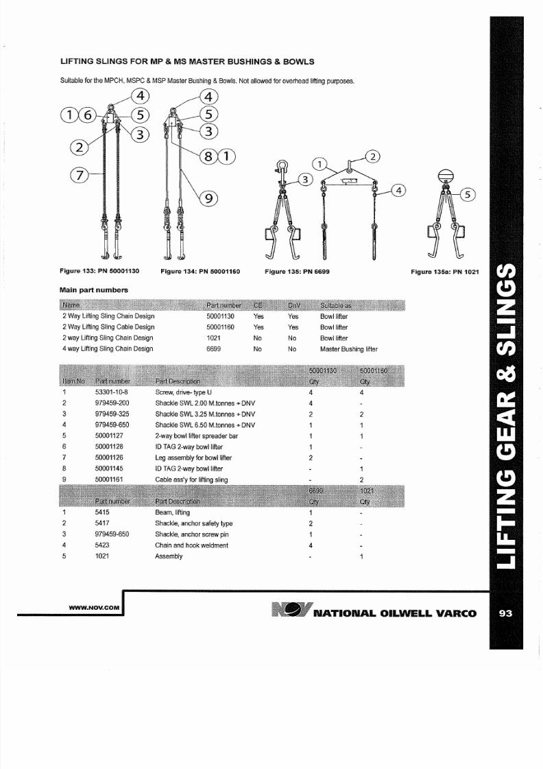
7/25/2019 Rotary Care & Maintenance Handbook
http://slidepdf.com/reader/full/rotary-care-maintenance-handbook 95/116
LIFTING SLINGS FOR MP MS MASTER BUSHINGS BOWLS
Suitable for the
MPCH,
MSPC MSP Master Bushing
Bowls.
Not
allowed
for overhead lifting
purposes.
4
Figure 133: PN 50001130
Figure 134: PN 50001160
Figure 135: P 6699
Figure 135a: P 1021
Main part numbers
2 Way Lifting Sling Chain
Design
50001130
Yes Yes
Bowl lifter
2 Way
Lifting
Sling
Cable Design
50001160 Yes
Yes
Bowl lifter
2way Lifting
Sling
Chain Design
1021
No No Bowl
lifter
4
way Lifting
Sling
Chain Design
6699 No
No Master Bushing
lifter
53301-10-8
Screw, drive-
type
U
4 4
2 979459-200
Shackle SWL 2.00 M.tonnes + DNV
4
3
979459-325
Shackle SWL 3.25 M
tonnes
+
DNV
2 2
4 979459-650
Shackle
SWL
6.50 M.tonnes +
DNV
1
5 50001127
2-way bowl lifter spreader bar
6
50001128
ID TAG
2-way bowl lifter
7 50001126
Leg
assembly for bowl
lifter
2
8
50001145 ID
TAG 2-way bowl lifter
1
9 50001161
Cable ass y for lifting
sling
2
5415
Beam, lifting
2 5417
Shackle, anchor safety type
2
3
979459-650
Shackle,
anchor screw
pin
4
5423
Chain and hook weldment
4
5 1021
Assembly
WWW NOV COM
N TION L OILWELL
V RCO
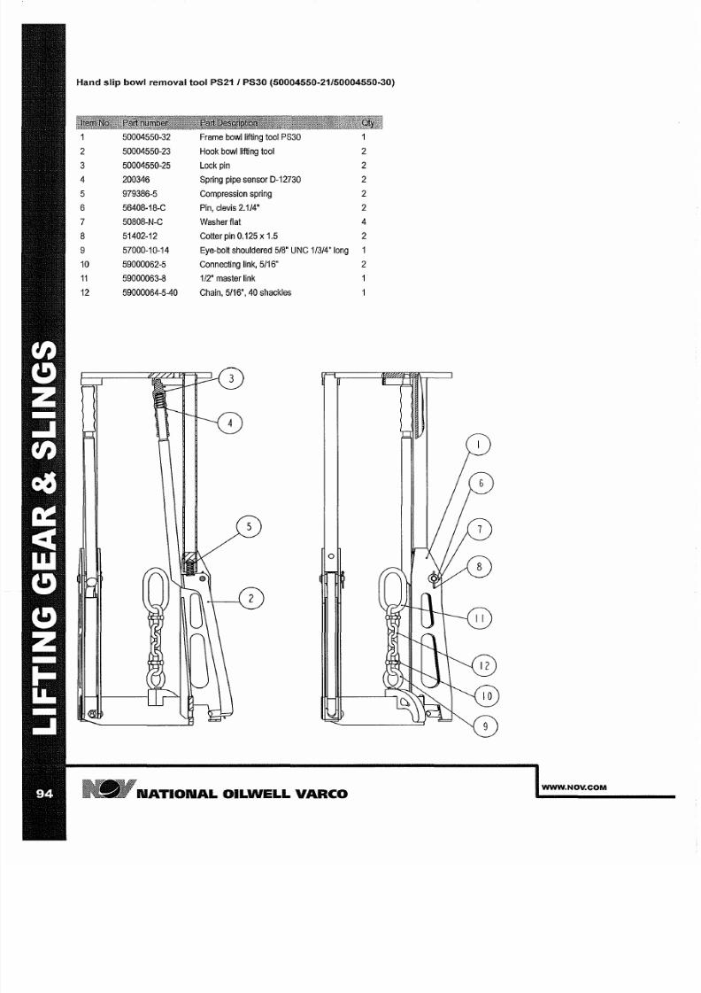
7/25/2019 Rotary Care & Maintenance Handbook
http://slidepdf.com/reader/full/rotary-care-maintenance-handbook 96/116
Hand slip bowl removal tool PS21 1PS3 50004550·21/50004550·30)
50004550-32 Frame bowl lifting tool PS30
50004550-23
Hook
bowl
lifting tool
3
50004550-25 Lock
pin
4
200346 Spring pipe sensor D-12730
5 979386-5
Compression
spring
6
56408-18-C
Pin,
clevis 2.1/4
7
50808-N-C
Washer flat
4
8 51402-12 Cotter
pin 0.125 x
1.5
9
57000-10-14 Eye-bolt shouldered
5/8 UNC 1/3/4'
long
10
59000062-5
Connecting
link, 5/16
59000063-8
1/2'
master
link
12
59000064-5-40 Chain,
5/16', 40
shackles
o
N TION L OILWELL V RCO
WWW NOV COM
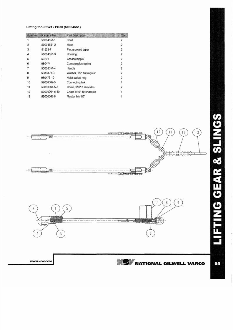
7/25/2019 Rotary Care & Maintenance Handbook
http://slidepdf.com/reader/full/rotary-care-maintenance-handbook 97/116
Lifting tool PS21 PS30 50004551)
50004551-1 Shaft
50004551-2
Hook
3
51503-7
Pin,
grooved
taper
4
50004551-3 Housing
5 53201 Grease
nipple
6
980474 Compression spring
7
50004551-4
Handle
8
50808-R-C
Washer, 1/2 flat regular
9
980473-10 Hoist swivel
ring
10
59000062-5
Connecting
link
4
59000064-5-8
Chain 5/16
8
shackles
12
59000064-5-40 Chain 5/16
40
shackles
13
59000063-8
Master
link 1/2
WWW NOV COM
NATIONAL
OILWELL
VARCO
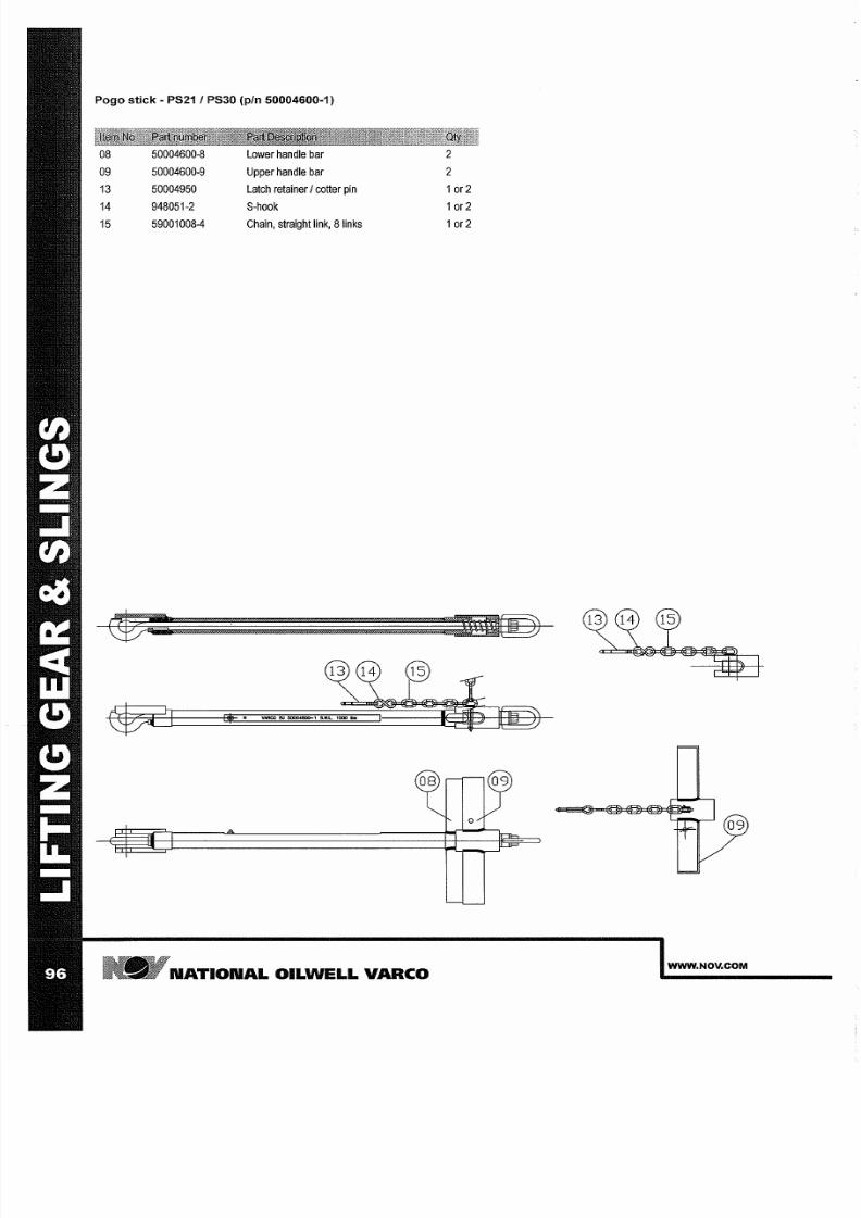
7/25/2019 Rotary Care & Maintenance Handbook
http://slidepdf.com/reader/full/rotary-care-maintenance-handbook 98/116
Pogo stick - PS21 I PS30 pIn 50004600-1
08
50004600-8
Lower
handle bar
2
09
50004600-9 Upper
handle
bar
2
13
50004950
Latch
retainer cotter
pin
or2
14
948051-2
S-hook or2
15
59001008-4 Chain
straight link
8
inks
or2
N TION L OILWELL V RCO
WWW NOV COM
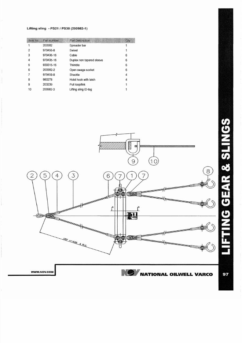
7/25/2019 Rotary Care & Maintenance Handbook
http://slidepdf.com/reader/full/rotary-care-maintenance-handbook 99/116
Lifting sling - PS21 PS30 200982-1)
200982
Spreader
bar
979456 8
Swivel
3
979436 16
Cable
6
4
979435 16 Duplex non tapered sleeve
6
5
939315 16
Thimble
6
6
200982 2
Open swage socket
6
7
979459 8
Shackle
4
8
980278
Hoist
hook with latch
4
9
203239
Puilioop/link
10 200982 3
Lifting
sling
ID tag
WWW NOV COM
N TION L OILWELL
V RCO
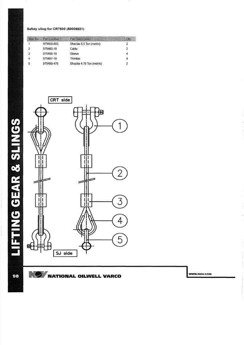
7/25/2019 Rotary Care & Maintenance Handbook
http://slidepdf.com/reader/full/rotary-care-maintenance-handbook 100/116
Safety sling for CRT500 50008021)
979459-650 Shackle 6.5
on
metric)
979460-18
Cable
3
979458-18 Sleeve
979457-18 Thimble
5
979459-475
Shackle 4.75 on
metric)
I RT
side
I
ISJ side
N TION L
OILWELL VARCO
WWW NOV COM
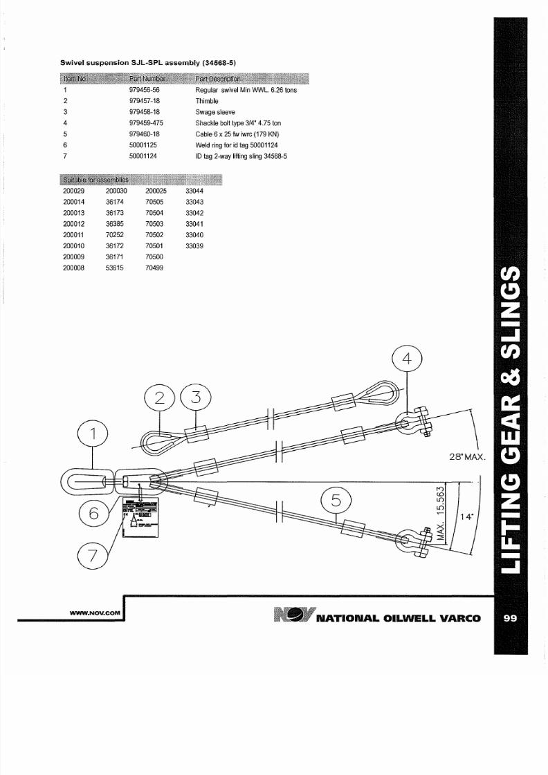
7/25/2019 Rotary Care & Maintenance Handbook
http://slidepdf.com/reader/full/rotary-care-maintenance-handbook 101/116
Swivel suspension SJL-5PL assembly 34568-5)
979456-56
Regular
swivel Min WWL. 6.26 tons
2
979457-18
Thimble
3
979458-18
Swage sleeve
4
979459-475
Shackle bolt type
3/4
4.75 ton
5
979460-18
Cable 6 x 25
w
iwrc
(179 KN)
6 50001125
Weld ring for i
tag
50001124
7
50001124
ID
tag 2-way lifting
sling 34568-5
200029 200030 200025
33044
200014
36174 70505
33043
200013 36173
70504
33042
200012
36385 70503
33041
200011
70252
70502
33040
200010 36172 70501
33039
200009 36171 70500
200008
53615
70499
28° MAX.
WWW NOV COM
N TION L
OILWELL
V RCO

7/25/2019 Rotary Care & Maintenance Handbook
http://slidepdf.com/reader/full/rotary-care-maintenance-handbook 102/116
N TION L OILWELL V RCO
WWW NOV COM
7/25/2019 Rotary Care & Maintenance Handbook
http://slidepdf.com/reader/full/rotary-care-maintenance-handbook 103/116
D PTER
RINGS
WWW NOV COM
N TION L OILWELL VARCO
7/25/2019 Rotary Care & Maintenance Handbook
http://slidepdf.com/reader/full/rotary-care-maintenance-handbook 104/116
N TION L OILWELL V RCO
WWW NOV COM
7/25/2019 Rotary Care & Maintenance Handbook
http://slidepdf.com/reader/full/rotary-care-maintenance-handbook 105/116
ADAPTER RINGS
Adapter
rings, both solid and hinged to be used for creating a
smaller
hole for accommodating
smaller (power) slips. Adapter
rings
are
considered to
be
ISO 14693:2003
7K devices.
Maintenance inspection
The owner and user together with the
manufacturer should
jOintly develop and update
inspection,
maintenance, repair and remanufacture procedures
consistent
with
equipment application,
loading,
work environment,
usage
and
other operational conditions.
These factors
may
change from
time
to
time
as
a result
of
new
technology,
equipment
history,
product improvements, new maintenance techniques
and
changes in service conditions. Alternatively,
NOV recommends using the
Periodic inspection
and
maintenance categories
and frequencies as
mentioned
in API
RPBB
Table
1.
NOV
Recommends the following inspection intervals according to API RPSB
5.3.2.2 Category
I
This
category involves observing the equipment during
operation
for indications of inadequate
performance.
When
in use, equipment shall be visually
inspected
on a
daily
basis for cracks, loose
fits
or connections, elongation of parts, and
other signs of
wear, corrosion or overloading. Any
equipment
found to show cracks,
excessive
wear, etc.,
shall
be
removed from service
for
further examination.
The
equipment
shall be
visually
inspected by a
person knowledgeable in that equipment and
its
function.
5.3.2.3
Category
II
This
is
Category
I
nspection plus further inspection for corrosion, deformation,
loose
or missing
components, deterioration,
proper lubrication, visible
external
cracks, and adjustment.
5.3.2.4 Category III
This
is
Category
II inspection
plus further
inspection,
which should include
NDT of critical areas
and may involve some disassembly to access specific
components
and to
identify wear that
exceeds the
manufacturer s allowable tolerances.
5.3.2.5
Category
IV
This
is
Category
III
inspection plus
further inspection for
which
the
equipment
is
disassembled
to the extent necessary to
conduct
NDT
of
all
primary
load-carrying
components as defined by manufacturer.
Equipment shall
be:
disassembled in asuitably-equipped facility
to
the extent necessary
to
permit
full
inspection
of
all primary-Ioad-carrying components and other components that are critical to the equipment; inspected for
excessive
wear,
cracks, flaws and
deformations. Corrections shall
be
made in accordance with the manufacturer s recommendations. Prior to Category III and
Category
IV
inspections, all
foreign material
such
as
dirt, paint,
grease,
oil, scale,
etc.
shall be removed from
the
concerned parts by asuitable method (e.g. paint
stripping, steam-cleaning, grit-blasting).
Detailed instructions for inspection
Weekly acc. to
at II
1
Visually
inspect and
repair
when needed.
2 Check for worn and damaged
parts
3
Check for
loose
and missing parts
4 Check
condition
of
shackles
and or hooks
5 Check
condition
of
springs
when
present
6
Check
for wear of
the any pins
7 Check that the
product
works flawlessly without interference
B
Check
state
of
lubrication
9
Check for any visible cracks
10. Check good condition of all primary and secondary retention
If
ANY suspicion is
risen
about the
condition
of the
tool, carry out acategory IV-inspection
Semi annual acc. to Cat
Carry out the
Cat
II inspection.
If
ANY
suspicion is
risen
about
the
condition of
the tool, carry out acategory
IV-inspection
Annually acc. to Cat IV
Carry out
the Cat III
inspection +
a
ull
MagnetiC Particle Inspection
of
all
primary
load bearing load components:
1.
Hooks
2 Chains
3
Cables
4.
Beams
see Critical Area Drawings, when no Critical area drawing
is
available, the
complete
part
is
considered
critical
Detailed instructions for Maintenance
Lubricate
the tool
regularly
during usage and
storage
to
prevent
corrosion from
attacking any part
of the operating
mechanism.
Routine lubrication should be
completed
prior
to
use.
1 Grease any hinge, latch and lock pins.
2 Grease any
grease
nipples.
3 Grease any
springs.
4.
Grease retainers asteners.
Instructions for Use
WWW NOV COM
N TION L OILWELL V RCO
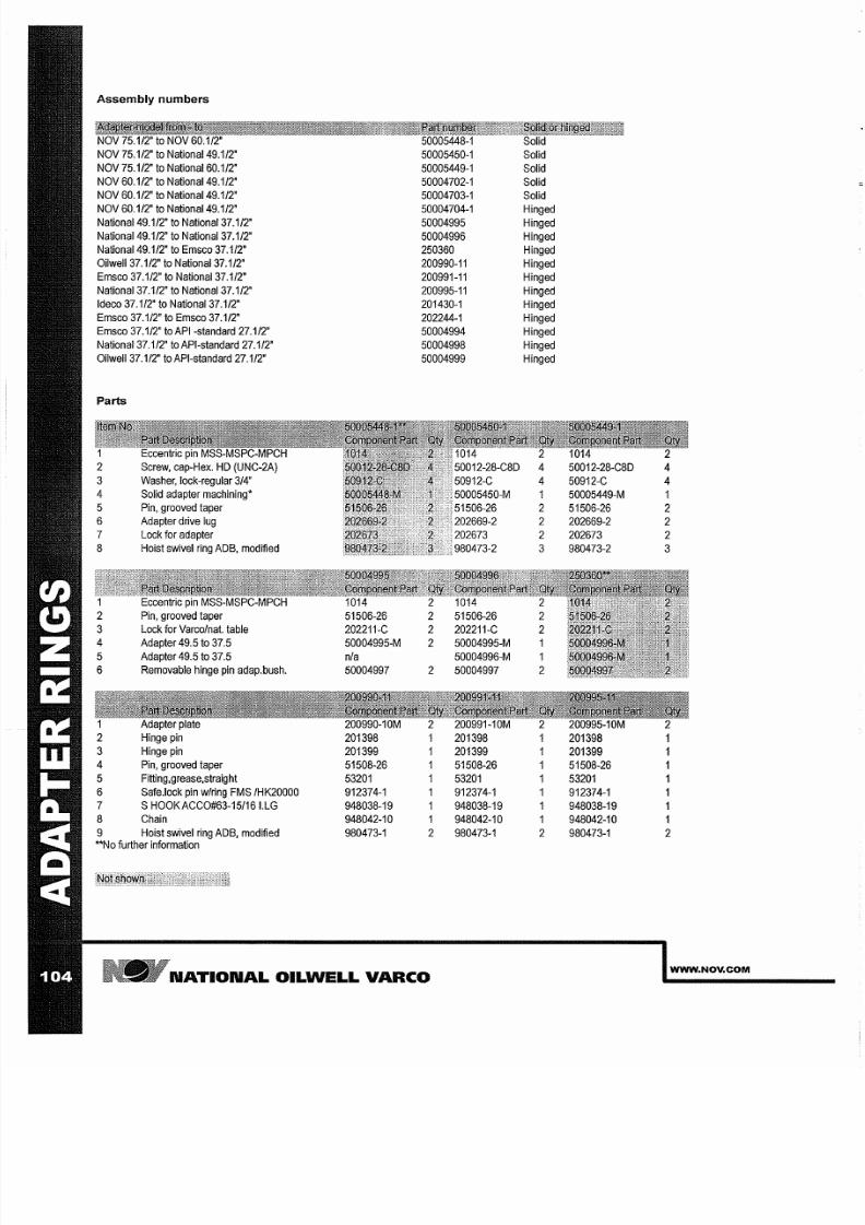
7/25/2019 Rotary Care & Maintenance Handbook
http://slidepdf.com/reader/full/rotary-care-maintenance-handbook 106/116
Assembly numbers
NOV
75.1/2
to National 49.1/2'
NOV
75.1/2
to National 60.1/2'
NOV
60.1/2
to National 49.1/2'
NOV 60.1/2 to National
49.1/2
NOV
60.1/2'
to National
49.1/2
National
49.1/2' to National
37.1/2
National
49.1/2
to National
37.1/2
National 49.1/2' to
Emsco
37.1/2'
OilweIl37.1/2' to National 37.1/2'
Emsco
37.1/2
to National 37.1/2'
National
37.1/2' to National
37.1/2
Ideco
37.1/2
to National 37.1/2'
Emsco 37.1/2' to Emsco 37.1/2'
Emsco 37.1/2 toAPI-standard 27.1/2'
National 37.1/2 to
API-standard
27.1/2'
OilweIl37.1/2 to
API-standard
27.1/2
arts
Eccentric
pin MSS-MSPC-MPCH
Screw, cap-Hex. HD (UNC-2A)
Washer, lock-regular 3/4'
Solid
adapter
machining'
5 Pin, grooved taper
6
Adapter drive
lug
7 Lock for
adapter
8 Hoist swivel ring ADS,
modified
pin
MSS-MSPC-MPCH
Pin, grooved taper
Lock for Varco/nat. table
4 Adapter 49.5
to
37.5
5 Adapter 49.5
to
37.5
6
Removable hinge pin
adap.bush.
plate
2
Hinge pin
3
Hinge
pin
4 Pin, grooved taper
5 Fitting,grease,straight
6
Safe.lock pin wIring FMS IHK20000
7 S
HOOKACC0#63-15/16I.LG
8
Chain
9
Hoist swivel
ring ADS,
modified
No
further information
51506-26
202211-C
50004995-M
n/a
50004997
200990-1O
201398
201399
51508-26
53201
912374-1
948038-19
948042-10
980473-1
50005450-1
50005449-1
50004702-1
50004703-1
50004704-1
50004995
50004996
250360
200990-11
200991-11
200995-11
201430-1
202244-1
50004994
50004998
50004999
1014
51506-26
202211-C
2
50004995-M
50004996-M
2
50004997
51508-26
53201
912374-1
948038-19
1
948042-10
2
980473-1
N TION L OILWELL V RCO
Solid
Solid
Solid
Solid
Hinged
Hinged
Hinged
Hinged
Hinged
Hinged
Hinged
Hinged
Hinged
Hinged
Hinged
Hinged
1
2
2
2
3
2
1
1
2
1
1
1
1
2
50012-28-C8D
50912-C
50005449-M
51506-26
202669-2
202673
980473-2
200995-1O
201398
201399
51508-26
53201
912374-1
948038-19
948042-10
980473-1
4
1
2
2
2
3
1
1
1
1
2
WWW NOV COM

7/25/2019 Rotary Care & Maintenance Handbook
http://slidepdf.com/reader/full/rotary-care-maintenance-handbook 107/116
Adapter plate
2
Hinge
pin
3
Hinge
pin
4
Pin, grooved taper
5
Fitting,grease,straight
6
Safe.lock pin wiring
FMS
IHK20000
7
S
HOOKACC0 63-15/16I.LG
8
Chain
9
Hoist swivel ring ADB, modified
2
50005448-1,50005450-1 50005449-1
50004995,50004996 250360
3
' -HI-- H-1 8
5
200990-11,200991-11,200995-11,201430-1 202244-1
WWW.NOV.COM
NATIONAL
OIL
W LL VARCO
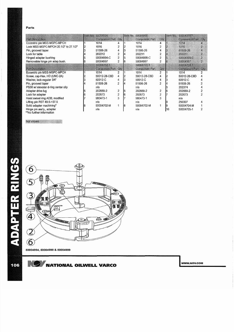
7/25/2019 Rotary Care & Maintenance Handbook
http://slidepdf.com/reader/full/rotary-care-maintenance-handbook 108/116
Parts
Eccentric
pin 1014
1014
Screw,
cap-Hex.
HD
(UNC-2A) 50012-28-C8D
50012-28-C8D
Washer, lock-regular 3/4 50912-C 50912-C
Pin,
grooved
taper 51506-26 2
51506-26
PS30 wi elevator
d-ring center slip
n/a
n/a
202374
Adapter drive lug
202669-2 2
202669-2 2 202669-2
Lock
for
adapter 202673 2 202673 2
202673
Hoist swivel ring ADS, modified 980473-1
3
980473-1
3
n/a
Lifting
pin
RST
49.5->37.5
n/a
n/a
250307
4
Solid adapter
machining
50004702-M 50004702-M
50004704-M 1
Hinge
pin
ass y., adapter n/a n/a 10
50004705-1
2
No further
information
CSJ
i
50004994 50004998 50004999
N TION L OILWELL
VARCO
WWW NOV COM
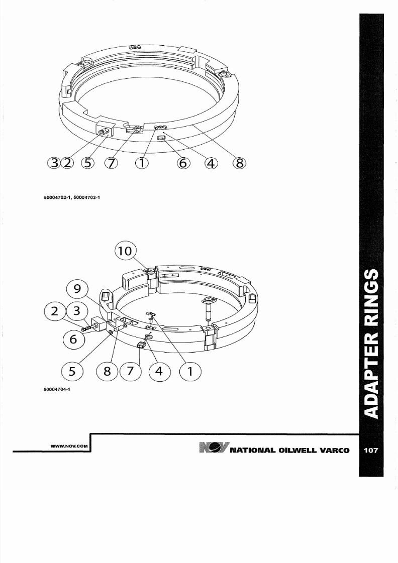
7/25/2019 Rotary Care & Maintenance Handbook
http://slidepdf.com/reader/full/rotary-care-maintenance-handbook 109/116
50004702-1 50004703-1
50004704-1
WWW.NOV.COM
N TION L
OILWELL
V RCO

7/25/2019 Rotary Care & Maintenance Handbook
http://slidepdf.com/reader/full/rotary-care-maintenance-handbook 110/116
N TION L OILWELL V RCO
WWW NOV COM

7/25/2019 Rotary Care & Maintenance Handbook
http://slidepdf.com/reader/full/rotary-care-maintenance-handbook 111/116
P R T ST
WWW NOV COM
NATIONAL OILWELL VARCO

7/25/2019 Rotary Care & Maintenance Handbook
http://slidepdf.com/reader/full/rotary-care-maintenance-handbook 112/116
N TION L OILWELL V RCO
WWW NOV COM
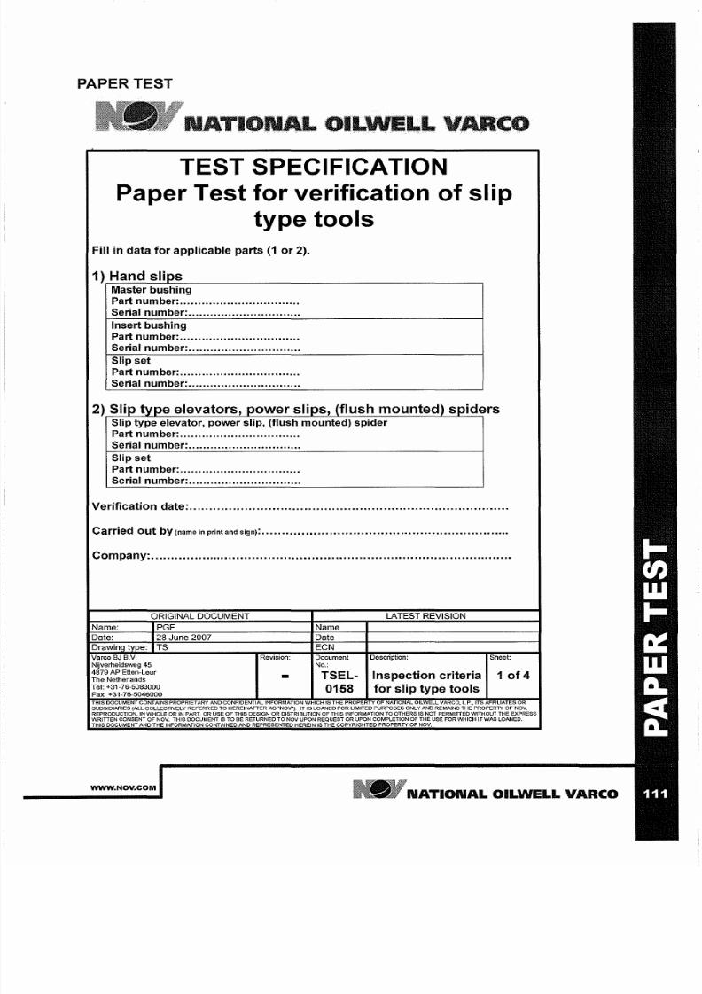
7/25/2019 Rotary Care & Maintenance Handbook
http://slidepdf.com/reader/full/rotary-care-maintenance-handbook 113/116
PAPER TEST
NATI 01
TEST SPECIFICATION
Paper
Test
for verification of slip
type tools
Fill in data for applicable parts 1 or 2).
1) Hand slips
Master bushing
Part number:
Serial number:
Insert bushing
Part
number:
.................................
Serial number: ...............................
Slip set
Part
number:
.................................
Serial number:
..............................
2) Slip type elevators, power slips, flush mounted) spiders
Slip type elevator, power slip, flush mounted) spider
Part number:
.................................
Serial
number:
...............................
Slip set
Part number:
.................................
Serial
number:
...............................
Verification date: .................................................................................
Carried out by name in
and sign): • • • • • • • • • • • • • • • • • • • • • • • • • • • • • • • • • • • • • • • • • • • • • • • • • • • • • • • • • • •
••••
Company:
............................................................................................
ORIGINAL DOCUMENT
LATEST REVISION
Name: PGF Name
Date:
28 June 2007
Date
Drawing type:
TS ECN
Varco
J B.v.
Revision: Document Description: Sheet:
Nijverheidsweg 45 No.:
4879 AP Etten-Leur
The Netherlands
TSEL- Inspection criteria
1 f 4
Tel: +31-7£>-5083000
0158
for
slip type tools
Fax: +31-7£>-5046000
THIS DOCUMENT CONTAINS PROPRIETARY AND CONFIDENTIAL INFORMATION WHICH IS THE PROPERTY OF NATIONAL OILWELL VARGO, L.P., ITS AFFILIATES OR
SUBSIDIARIES ALL COLLECTIVELY REFERRED TO HEREINAFTER AS ··NOV·).
IT
IS LOANED FOR LIMITED PURPOSES ONLY AND REMAINS THE PROPERTY
OF
NOV.
REPRODUCTION, IN WHOLE OR IN
PART,
OR USE OF THIS DESIGN OR DISTRIBUTION OF THIS INFORMATION TO OTHERS IS NOT PERMITIeO WITHOUT THE EXPRESS
WRITIEN CONSENT OF
NOV.
THIS DOCUMENT
IS TO
BE RETURNED
TO NOV
UPON REQUEST
OR UPON C OMPLETION OF
THE
USE FOR
WHICH
IT WAS LOANED.
THIS DOCUMENT AND THE INFORMATION CONTAINED AND REPRESENTED HEREIN IS THE COPYRIGHTED PROPERTY OF NOV.
WWW NOV COM
NATIONAL OILWELL VARCO
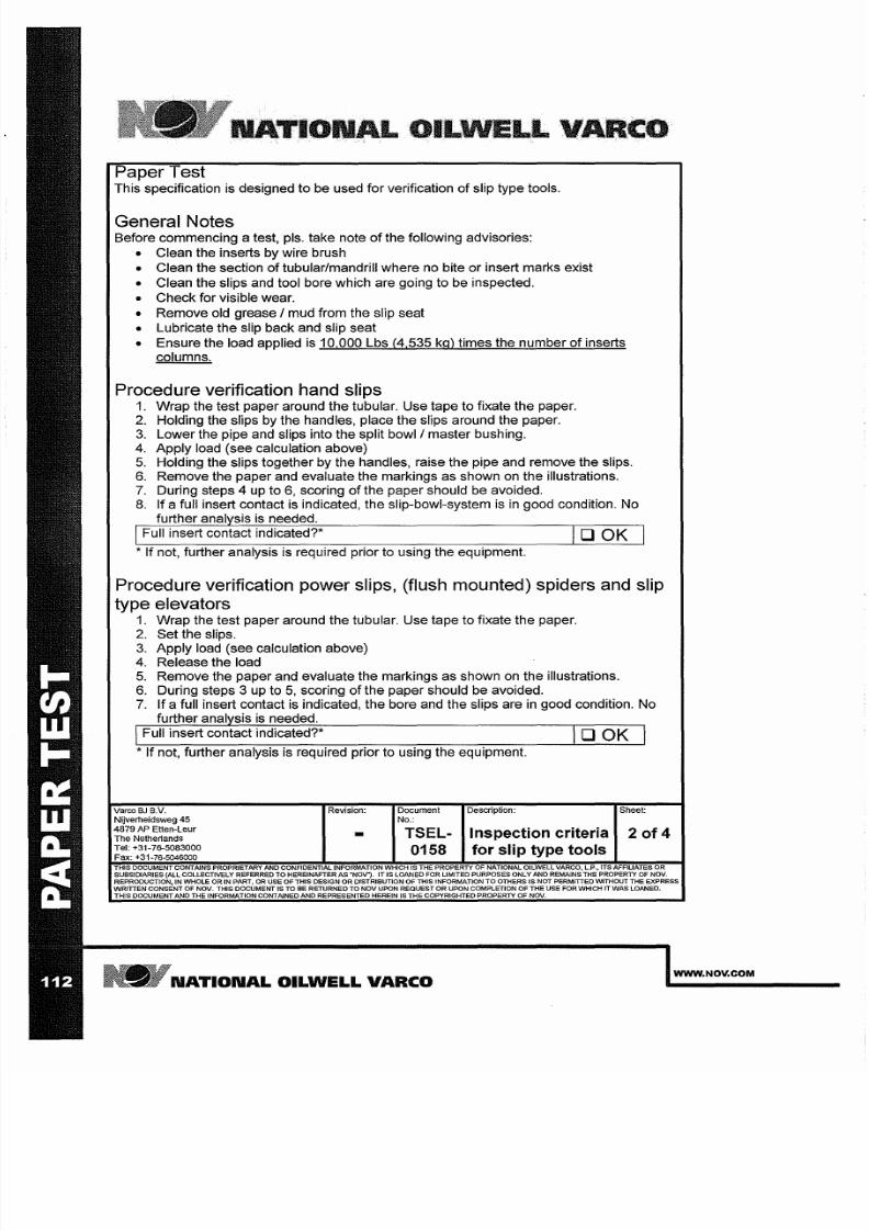
7/25/2019 Rotary Care & Maintenance Handbook
http://slidepdf.com/reader/full/rotary-care-maintenance-handbook 114/116
L OILWELLVAIlCO
Paper Test
This specification is designed
to
be used for verification of slip type tools.
General Notes
Before commencing a test, pis. take note of the following advisories:
• Clean the inserts by wire brush
• Clean the section of tubular/mandrill where no bite or insert marks exist
• Clean the slips and tool bore which are going to be inspected.
• Check for visible wear.
• Remove old grease / mud from the slip seat
• Lubricate the slip back and slip seat
• Ensure the load applied is 10,000 Lbs
4,535
kg) times the number of inserts
columns.
Procedure verification hand slips
1.
Wrap the test paper around the tubular. Use tape to fixate the paper.
2. Holding the slips by the handles, place the slips around the paper.
3. Lower the pipe and slips into the split bowl/master bushing.
4. Apply load (see calculation above)
5 Holding the slips together by the handles, raise the pipe and remove the slips.
6. Remove the paper and evaluate the markings as shown on the illustrations.
7. During steps 4 up to 6 scoring of the paper should be avoided.
8. If a full insert contact
is
indicated, the slip-bowl-system
is in
good condition. No
further analysis is needed.
I
Full insert contact indicated?*
lOOK
I
* If not, further analysis is required prior to using the equipment.
Procedure verification power slips, (flush mounted) spiders and slip
type elevators
1.
Wrap the test paper around the tubular. Use tape to fixate the paper.
2.
Set the slips.
3. Apply load (see calculation above)
4. Release the load
5. Remove the paper and evaluate the markings as shown on the illustrations.
6. During steps 3 up to 5 scoring of the paper should be avoided.
7. If a full insert contact is indicated, the bore and the slips are in good condition. No
further analysis
is
needed.
I
Full insert contact indicated?* lOOK
* If not, further analysis is required prior to using the equipment.
Voreo
SJ
s.v.
Revision: Document Description: Sheet:
Nijverheidsweg 45 No.:
4879
AP Etten-Leur
-
TSEL
Inspection criteria
of4
The
Nether1ands
Tel: +31-76-5083000
0158
for slip type tools
Fax: +31-76·5046000
THIS DOCUMENT CONTAINS PROPRIETARY AND CONFIDENTIAL INFORMATION WHICH
IS
THE PROPERTY OF NATIONAL OILWELL VARCO. L.P.,ITS AFFILIATES OR
SUBSIDIARIES
ALL
COLLECTIVELY REFERRED TO HEREINAFTER AS NOV ).
IT
IS LOANED FOR LIMITED PURPOSES ONLY AND REMAINS THE PROPERTY OF NOV.
REPRODUCTION, IN
WHOLE
OR IN PART, OR USE OF THIS DESIGN OR DISTRIBUTION OF THIS INFORMATIONTO OTHERS
IS
NOT PERMITTED WITHOUT
THE
EXPRESS
WRITTEN CONSENT OF NOV. THIS DOCUMENTIS TO BE RETURNED TO NOV UPON REQUEST OR UPON COMPLETION OF THE USE FOR WHICH IT WAS LOANED.
THIS DOCUMENT AND THE INFORMATION CONTAINED AND REPRESENTED HEREIN IS THE COPYRIGHTED PROPERTY OF NOV.
NATIONAL OILWELL
VARCO
WWW.NOV.COM
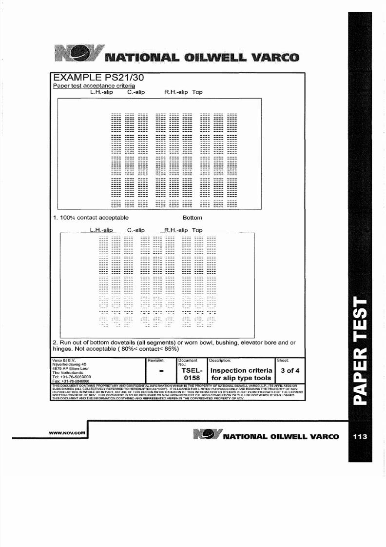
7/25/2019 Rotary Care & Maintenance Handbook
http://slidepdf.com/reader/full/rotary-care-maintenance-handbook 115/116
NAT'IONAL OlfLWELL VAR
EXAMPLE PS21/30
Paper
test acceptance criteria
L.H.-slip
C.-slip R.H.-slip Top
1/'.. .,.
W.;,.. '
w - ~
'. . *
1. 100
contact
acceptable
Bottom
L.H.-slip
C.-slip R.H.-slip Top
2.
Run out of bottom
dovetails
(all
segments)
or worn bowl, bushing, elevator bore and or
hinges. Not acceptable (80 < contact< 85 )
Vareo
BJ
B
V
Revision:
Document Description: Sheet:
Nijverheidsweg 5
No.:
4879 AP Etten-Leur
TSEL- Inspection criteria
3 f4
he Netherlands
el: +31-76-5083000
0158 for slip type tools
Fax: +31-76-5046000
THIS DOCUMENT CONTAINS PROPRIETARY AND
CONFIDENnAL
INFORMATION WHICH IS THE PROPERTY OF NATIONAL OILWELL VARCO, LP . ITS AFFILIATESOR
SUBSIDIARIES (ALL COLLECTIVELY REFERRED
TO
HEREINAFTER AS NOV ). IT IS LOANED FOR LIMITED PURPOSES ONLY AND REMAINS THE PROPERTY OF NOV.
REPRODUCTION, IN WHOLE OR IN PART, OR USE OF THIS DESIGN OR DISTRIBUTION OF THIS INFORMATION
TO
OTHERS IS NOT PERMITIED WITHOUT THE EXPRESS
WRiTIEN CONSENT OF NOV. THIS DOCUMENT IS TO BE RETURNED TO
NOV
UPON REQUEST
OR
UPON COMPLETION OF THE USE FOR WHICH IT WAS LOANED.
THIS DOCUMENT AND THE INFORMATION CONTAINED AND REPRESENTED HEREIN IS THE COPYRIGHTED PROPERTY OF NOV.
WWW NOV COM
NATIONAL OILWELL VARCO
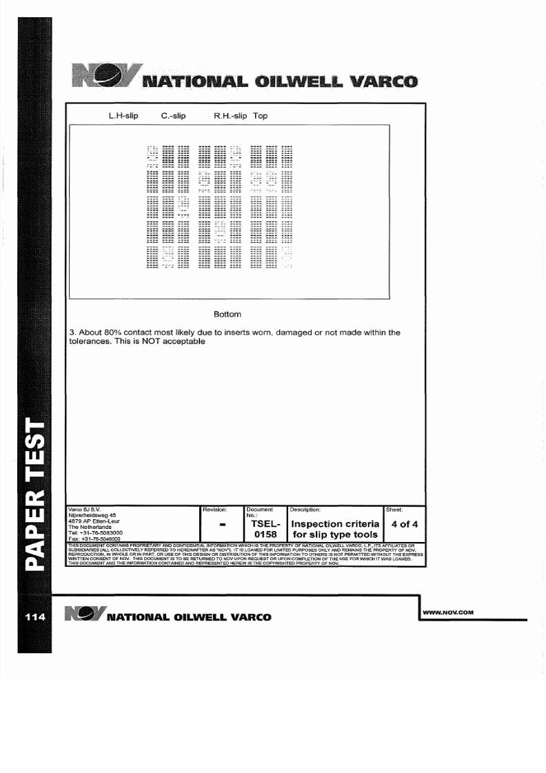
7/25/2019 Rotary Care & Maintenance Handbook
http://slidepdf.com/reader/full/rotary-care-maintenance-handbook 116/116
LL
L.H-slip C.-slip R.H.-slip Top
f ,- iJ/ ' ;,-
t
. . . ;
'*1<> ........
....... ..
~ : ; , . -
...;;..
....
' ...
.. ~ . . , .
N
_.-
. .
~ * - i i i
: : ~ :
Will ,
" " ~ * ' *
'W .
<r
;;..;;,;..
''''' .. '
..... .
.. ...........
...... ... ..
'
.......
~ ' ' ' ' ' ' ' W
.............
~ ' i I . . , - + :
:
' i t ~ , *
.... ...
- --
.
.............
' ..
-...
-
.. ..., ...
...
<;> .
... ...
..
0; . . .
,.. ..... »
,'
....
'
..... ',...
'., ..
<C ..
'
.
'
..,
,., ,. '
' -
:
, , , ,«.,.
.
.
~ . «
..... ' .
.._ '
... '
.....
..... ,...
...........
,., .......
_.......
,.
.......
....... '.,..
......
</¥
........
1 f ' . * ~ '
..........
, , >10:
.....
'
'
....
'
..,
'
.......
............
...........
...
..,
............
---
.............
-_
....
.,,,,..
;,,* .. ,. ....*
-oX »
~ , , '
,.,
...
,... ....
-
...or
..
, ,
..........
,..
...
.
..,,. '
........
........ ,..,..
.
.........
-
_
.......
...
' « , . , .
M W , ~
*
..
'i<P'Ift'
........
-- .....
...... ...
' ....
. . . . - ~
...
Bottom
3.
About 80% contact most likely due to inserts worn, damaged or not made within the
tolerances. This
is
NOT acceptable