Embed Size (px)
Citation preview
MIO-R46RXD21150 (Rev A)
G&B Specialties Inc. 535 West 3rd
Street, Berwick, PA, USA Tel: (570) 752-5901 Fax: (570) 752-6397
- 1 -
INSTALLATION, OPERATIONS, SERVICE AND PARTS
ROTARY FRONT R-460 RAILGEAR
2011 DODGE 4500/5500
FT RAILGEAR SERIAL # ______________________
RR RAILGEAR SERIAL# ______________________
IN-SERVICE DATE _____________________

MIO-R46RXD21150 (Rev A)
G&B Specialties Inc. 535 West 3rd
Street, Berwick, PA, USA Tel: (570) 752-5901 Fax: (570) 752-6397
- 2 -
SAFETY PRECAUTIONS
If any installation problems are encountered, please call G&B Specialties for
technical assistance before continuing with the installation process.
• Failure to heed to any of the following warnings could result in severe
bodily injury and/or equipment damage.
• Read and understand this manual completely before attempting
installation of the equipment.
• Installation instructions provided below only address the Rafna
Industries railgear equipment. Applicable railway company
procedures and policies must be adhered to.
• Before performing any work under the vehicle or railgear, ensure the
engine is turned off and the parking brake is set.
• Do not start the vehicle with the power steering hoses disconnected.
Reconnect all hoses, and secure the power steering cooler if the vehicle
is started.
• Ensure all removed components are given to the vehicle owner after
the installation of the railgear. These components must be re-installed
if the railgear is removed from the vehicle.
• Always disconnect the vehicle’s battery when welding on the vehicle
or railgear in order to protect the vehicle’s electrical system.
!

MIO-R46RXD21150 (Rev A)
G&B Specialties Inc. 535 West 3rd
Street, Berwick, PA, USA Tel: (570) 752-5901 Fax: (570) 752-6397
- 3 -
1.0 INSTALLATION
RAILGEAR INSTALLATION
1. Remove the front bumper and front tow hooks if so equipped.
2. Retain the front bumper for re-installation. The front bumper will need to be modified
as required.
3. Remove the Lock Cam from the upper cross frame assembly by removing the (3) 3/8”
bolts securing the lock cam to the cam base.
4. Loosen, but do not remove the 3/8” bolts securing the front support beam assembly
to the railgear mounting brackets. Loosen the jam nuts and turn the adjusting rod to
shorten the support beam until there is approximately 1/8”-1/4” gap between the
support beam mounting plates and each railgear mounting bracket.
5. Loosen, but do not remove, the (8) 1/2" bolts securing the railgear bearing caps to the
upper cross frame assembly.
6. Remove the 1/2" and 5/8" bolts securing the outer support plates to the railgear
mounting brackets. Do not remove the 1" bolt securing the cylinder.. Use caution as
the outer support plates will swing downward and free once the 1/2" and 5/8"
hardware is removed.
7. Slide the railgear under the front frame horns and raise the unit into place. The
railgear mounting brackets should sit flush with the bottom of the vehicle frame and
flush to the inside of the vehicle frame.
8. The slots/holes in the railgear mounting brackets should line up with the holes in the
frame.
Table 1.2: Front Railgear Kit (R-21150) Installation Parts (Cable Lock)
Part Number Description Qty
R-21150A R-460 Rotary Front Upper Assembly 1
R-001 10” Steel Wheel Assembly 2
R-20120D Rail Sweep, Drivers Side 1
R-20120P Rail Sweep, Passengers Side 1
K-R45RXFCAM002A Lock Cam Kit, Standard 1
R-990KIT-204C Wheel Mounting Hardware 2
MIO-R46RXD21150 (Rev A)
G&B Specialties Inc. 535 West 3rd
Street, Berwick, PA, USA Tel: (570) 752-5901 Fax: (570) 752-6397
- 4 -
9. Swing the outer support plates up into place and align the slots with the holes in the
frame.
10. Secure the mounting brackets to the vehicle frame with the included 1/2" and 5/8”
hardware. Torque to the 1/2" bolts 100 ft-lbs dry and the 5/8" bolts 150 ft-lbs dry
11. Center the upper cross frame assembly to the railgear mounting brackets and tighten
the (8) 1/2" bolts securing the railgear bearing caps to the upper cross frame
assembly, do not torque at this time.
12. Turn the adjusting rod to lengthen the support beam until there is no gap between the
support beam mounting plates and both railgear mounting brackets. Adjust until just
tight. Do not over tighten as this will force the front frame rails to spread apart.
Tighten jam nuts.
13. Tighten 3/8” support beam fasteners to 40 ft-lbs dry.
14. Weld the railgear mounting brackets and outer support plates to the vehicle frame as
shown.
Proceed to install the railgear hydraulic system as per the Hydraulic Kit Installation
manual before continuing with the following steps.
1. Follow the Railgear Lock System Installation and adjustment Procedure detailed in
the Installation section of this manual.
2. Follow the Railgear Alignment procedure detailed in the Service section of this
manual.
3. Follow the Vehicle Axle Lockup Kit installation procedure detailed in the Axle
Lockup Kit Installation and Operation manual.
4. Follow the Rail Sweep Adjustment procedure detailed in the Service section of this
manual.
5. Torque all fasteners as detailed in the Service section of this manual.
6. Grease the railgear at all lubrication points as detailed in the Service section of this
manual.
7. Modify front bumper as required.

MIO-R46RXD21150 (Rev A)
G&B Specialties Inc. 535 West 3rd
Street, Berwick, PA, USA Tel: (570) 752-5901 Fax: (570) 752-6397
- 5 -

MIO-R46RXD21150 (Rev A)
G&B Specialties Inc. 535 West 3rd
Street, Berwick, PA, USA Tel: (570) 752-5901 Fax: (570) 752-6397
- 6 -

MIO-R46RXD21150 (Rev A)
G&B Specialties Inc. 535 West 3rd
Street, Berwick, PA, USA Tel: (570) 752-5901 Fax: (570) 752-6397
- 7 -

MIO-R46RXD21150 (Rev A)
G&B Specialties Inc. 535 West 3rd
Street, Berwick, PA, USA Tel: (570) 752-5901 Fax: (570) 752-6397
- 8 -

MIO-R46RXD21150 (Rev A)
G&B Specialties Inc. 535 West 3rd
Street, Berwick, PA, USA Tel: (570) 752-5901 Fax: (570) 752-6397
- 9 -
RAILGEAR LOCK SYSTEM INSTALLATION
The railgear lock system provides an automatic mechanical pin lock for the road and rail
position plus an additional over-center hydraulic lock in the rail position.
The lock cam should not be installed until the railgear unit is installed on the vehicle
and the over center adjustment has been made.
Installation (Cable Lock)
1. The front railgear unit is shipped with the cable actuated lock system and lock cable
installed.
2. Raise/Lower the railgear to either the fully locked rail or road position.
3. Place the lock cam against the cam base as shown, with the cam ID mark facing down
towards the railgear axle.
4. Loosely attach the lock cam to the cam base with the supplied 3/8” hardware.
Adjustment
1. The lock cam base is slotted to allow for easier adjustment of the lock pin/lock cam
engagement.
2. With the railgear in the fully locked rail or road position, and the lock pin engaged,
adjust the cam towards the lock pin. The cam should not be touching the lock pin.
There should be approximately 1/8” clearance between the lock pin and the lock cam.
3. Tighten but do not torque the 3/8” fasteners.
4. Disengage the railgear mechanical locking pin by pulling on the locking cable handle
or pull rod.
5. Proceed to rotate the railgear to the fully locked rail or road position. One the gear is
past the locked position, release the locking pin handle. The lock pin should ride
against the side of the cam.
6. Once the gear reaches the full locked position, the pin should automatically engage
the cam.
7. If the lock pin does not engage automatically, adjust the cam as necessary to allow for
automatic engagement in both the road and rail position. It may be necessary to grind
the cam slightly to allow for proper engagement of the lock pin.

MIO-R46RXD21150 (Rev A)
G&B Specialties Inc. 535 West 3rd
Street, Berwick, PA, USA Tel: (570) 752-5901 Fax: (570) 752-6397
- 10 -
8. Once the proper adjustment has been made, torque the 3/8" fasteners to 40 ft-lbs dry
then weld the cam to the cam base as shown.

MIO-R46RXD21150 (Rev A)
G&B Specialties Inc. 535 West 3rd
Street, Berwick, PA, USA Tel: (570) 752-5901 Fax: (570) 752-6397
- 11 -
Lock Cam Installation/Adjustment

MIO-R46RXD21150 (Rev A)
G&B Specialties Inc. 535 West 3rd
Street, Berwick, PA, USA Tel: (570) 752-5901 Fax: (570) 752-6397
- 12 -
2.0 OPERATIONS
With the railgear kit installed on this vehicle, it may be operated as normal, however the
vehicle has decreased ground clearance and angles of approach and departure due to the
railgear. Caution must be used when operating the vehicle.
Never operate the vehicle if the Gross Vehicle Weight Rating (GVWR), Gross Axle
Weight Rating Front or Rear (GAWR), or the wheel or tire load ratings are
exceeded.
Refer to the Hydraulic Kit Operation, Service, and Parts manual for information on the
location and operation of the railgear hydraulic system controls.
Placing The Vehicle On Rail – To Lower The Railgear:
1. Engage the vehicle front axle lock. Follow the Axle Lockup Kit Operation procedure
detailed in the Axle Lockup Kit Installation and Operation and Service manual.
2. Visually check that the vehicle front axle lock is fully engaged.
3. Disengage the railgear mechanical locking pin by pulling on the locking cable handle.
Do not force the locking cable. If the lock pin cannot be disengaged, raise or lower
the railgear slightly.
4. Hold the locking cable handle in the disengaged position.
5. Lower the railgear and release the locking cable handle once the railgear has rotated
past the road locked position.
6. As the railgear is being deployed, it will start taking some of the vehicle’s load. The
railgears spring suspension should be observed compressing at least 1” under this
load.
7. Continue lowering the railgear until the hydraulic cylinders are fully extended and the
railgear lock pin is fully engaged. In this position, the railgear should be about 3º-5 º
over center and the vehicle front tires should be approximately 2”-3” above the rail.
8. Visually check that the vehicle front axle lock is fully engaged.
MIO-R46RXD21150 (Rev A)
G&B Specialties Inc. 535 West 3rd
Street, Berwick, PA, USA Tel: (570) 752-5901 Fax: (570) 752-6397
- 13 -
Removing The Vehicle From Rail – To Raise The Railgear:
1. Disengage the railgear mechanical locking pin by pulling on the locking cable handle.
Do not force the locking cable. If the lock pin cannot be disengaged, raise or lower
the railgear slightly.
2. Hold the locking cable handle in the disengaged position.
3. Raise the railgear and release the locking cable handle once the railgear has rotated
past the rail locked position.
4. Raise the railgear fully. The railgear lock pin should engage automatically.
5. Disengage the vehicle front axle lock as per the Axle Lockup Kit Operation
procedure detailed in the Axle Lockup Kit Installation and Operation and Service
manual.

MIO-R46RXD21150 (Rev A)
G&B Specialties Inc. 535 West 3rd
Street, Berwick, PA, USA Tel: (570) 752-5901 Fax: (570) 752-6397
- 14 -
3.0 SERVICE
The railgear kit must be serviced regularly to avoid damage to the equipment. Table 1
below provides the Recommended Service Schedule and the detailed service procedures
follow.
Figure 1 provides the Non-Standard Fastener Torque Values. Table 2 provides Standard
Fastener Torque Values for all other fasteners.
Grease fittings are provided at all railgear lubrication points as shown in Figure 2. The
recommended lubricant for all lubrication points on this railgear is ESSO LONAX EP2
grease or equivalent. In cold weather areas/seasons, SHELL DARINA XL102 or
equivalent may be used.
Table 1: Recommended Service Schedule
DESCRIPTION
Dai
ly
1st 8
ho
urs
of
Op
erat
ion
Wee
kly
Mo
nth
ly
Ev
ery
3
Mo
nth
s
Ev
ery
6
Mo
nth
s
1 Visually inspect the railgear prior to use for damaged or worn parts �
2 Check for loose wheels and fasteners �
3 Ensure the rail gear locking mechanism is functioning properly in both
the road and rail positions
�
4 Check and adjust truck tire pressure as per requirements �
5 Ensure the vehicle is in good operating condition based on the vehicle
operating and maintenance instructions
�
6 Check and adjust rail wheel end play ( 0.005” max.) �
7 Inspect railgear wheel flanges for wear. Use the “Rafna Wheel Flange
Indicator” for measurement
�
8 Inspect all hydraulic fittings and hoses for leaks or wear �
9 Inspect rail sweeps for close proximity to rail head �
10 Grease inner tubes �
11 Lubricate locking mechanism �
12 Check level on hydraulic reservoir. Top off with appropriate filtered
fluid
�
13 Inspect and grease railgear wheel bearings �
14 Check and correct rail wheel alignment, if gear is removed or damaged,
or every 12 months Yearly
Note: For continuous service at ambient temperatures above 40°C ( 105°F), more frequent
lubrication is required.

MIO-R46RXD21150 (Rev A)
G&B Specialties Inc. 535 West 3rd
Street, Berwick, PA, USA Tel: (570) 752-5901 Fax: (570) 752-6397
- 15 -
Standard Fastener Torque Values
Fastener Size Fastener Torque Value (ft-lbs) Dry
1” UNC Gr. 8 Fasteners 250
¾” UNC Gr. 8 Fasteners 175 5/8” UNC Gr. 8 Fasteners 150
½” UNC Gr. 8 Fasteners 100 3/8” UNC Gr. 8 Fasteners 40
¼” UNC Gr. 8 Fasteners 12
Railgear Lubrication Points
MIO-R46RXD21150 (Rev A)
G&B Specialties Inc. 535 West 3rd
Street, Berwick, PA, USA Tel: (570) 752-5901 Fax: (570) 752-6397
- 16 -
Railgear Over-Center Adjustment
The railgear is designed to rotate slightly past vertical into the rail position in order to
provide a secondary safety feature in the event of a hydraulic and / or lock pin failure.
This additional rotation past vertical is called the over-center angle and is adjustable via a
threaded rod end on the end of the hydraulic cylinder. The location of the railgear in the
road position is also a function of the over-center adjustment, however, DO NOT use the
over-center adjustment to adjust the road position of the railgear. This will have adverse
effects on the over-center safety feature.
The over-center angle is defined as the angle between the vertical edge of the outer guide
tubes and the vertical. It can be measured with the vehicle on a level section of rail with
the railgear in the rail position using an angle meter. The over-center angle must be
between 3°-5° past vertical. If this is not the case, adjust as follows:
1. Unload the railgear hydraulic cylinder by raising the railgear just off rail.
2. Loosen the jam nut on the hydraulic cylinder rod end and adjust the rod end out to
increase the over-center angle or in to decrease the over-center angle. Note that the
cylinder rod can be turned instead of turning the rod end.
3. Re-deploy the railgear to the rail position and re-check the over-center angle. Re-
adjust as necessary.
4. Tighten the jam nut on the hydraulic cylinder rod end.
5. Repeat process for other cylinder.
6. Both cylinders should be adjusted so that both cylinders have the same amount of
stroke over center. This will help to eliminate any binding or twisting of the railgear
when deployed to the rail position.
7. Following the over-center angle adjustment, the railgear may contact the vehicle if
not enough clearance was left during installation. Check the railgear clearance to all
vehicle components throughout the full range of railgear and railgear suspension
movement. If there is interference with the vehicle bumper, it can be trimmed and
reinforced as required.
8. With the railgear fully raised to the road position, ensure that the railgear lock pin
properly engages the lock cam. It may be necessary to adjust and/or grind the lock
cam slightly to ensure proper fit.

MIO-R46RXD21150 (Rev A)
G&B Specialties Inc. 535 West 3rd
Street, Berwick, PA, USA Tel: (570) 752-5901 Fax: (570) 752-6397
- 17 -
Rail Wheel Bearing Adjustment
The rail wheel bearings require periodic adjustment in order to keep the endplay within
specification. If the rail wheel bearings are not correctly adjusted, failure may occur and
will not be covered under the railgear warranty. Check and adjust the bearing endplay
with the railgear in the road position and with the rail wheels free to turn.
Use a magnetic base dial gauge to measure the endplay of each rail wheel bearing. The
bearing endplay must be between 0.001” and 0.005”. If this is not the case, adjust as
follows:
1. Remove the rail wheel hubcap and gasket by removing the three 1/4” bolts and 1/4”
lock washers. Remove and discard the cotter pin from the 3/4” slotted spindle nut.
2. Ensure the wheel-bearing cavity is full of grease.
3. While rotating the rail wheel forward, torque the spindle nut to 20 ft-lbs. Then loosen
the spindle nut and re-torque it to 6 ft-lbs. Re-check and re-adjust the bearing endplay
if required. If no torque wrench is available, tighten the spindle nut until the rail
wheel is difficult to turn by hand. Then loosen the spindle nut and retighten it just
until no loose can be felt in the bearings. Re-adjust the bearing endplay with a torque
wrench as soon as possible.
4. Install a new 3/16” x 2” long cotter pin through the spindle nut. Tighten the spindle
nut slightly if needed to insert the cotter pin.
5. Re-install the hubcap and gasket using the 1/4” bolts and new 1/4” split lock washers.
Blue Loctite can be used on the bolts as an added safety measure. Tighten and torque
the 1/4” fasteners to 12 ft-lbs dry. Do not over torque.
Rail Sweep Adjustment
The distance between the rail sweep rubber and the rail is adjustable and should be
maintained at approximately 1/8”. To adjust the rail sweep rubber, with the railgear in
the rail position, loosen the two 1/4” fasteners that secure the rail sweep rubber to the rail
sweep bracket. Slide the rail sweep rubber up or down for the correct clearance. Tighten
and torque the 1/4” fasteners to 12 ft-lbs dry. Do not over torque.

MIO-R46RXD21150 (Rev A)
G&B Specialties Inc. 535 West 3rd
Street, Berwick, PA, USA Tel: (570) 752-5901 Fax: (570) 752-6397
- 18 -
RAILGEAR ALIGNMENT
The railgear must be correctly aligned in order to perform properly, safely, and avoid
excessive wear and derailment. The rail wheels can be independently aligned for toe-
in/toe-out and the railgear can be adjusted side to side (laterally) on the vehicle. A
parallel line system and the following procedure should be used to perform the railgear
alignment.
The rail wheel loads should be checked and adjusted, the vehicle should have had a four-
wheel alignment (with the complete railgear package installed on the vehicle and any
suspension modifications done) and the tires should be properly inflated prior to
performing the railgear alignment.
The railgear alignment is done with the vehicle on a straight and level section of rail with
the railgear in the rail position and the vehicle wheels pointing straight ahead. The
individual rail wheel alignment should be done first, followed by the lateral alignment of
the railgear.
Each rail wheel is aligned by loosening the four 1/2” fasteners that secure it to the
railgear axle. The rail wheel is then turned into alignment. The four 1/2” fasteners should
then be tightened and torqued to 100 ft-lbs dry. Do not over torque.
Lateral alignment is achieved by sliding the lower half of the railgear unit in the pivot
bearings. It may be necessary to loosen the bearing caps slightly to ease the adjustment
process. Once the railgear is in alignment, tighten the bearing caps to 40 ft-lbs dry. Do
not over torque.
Ensure that the railgear over-center adjustment has been made before continuing
Once the alignment is complete, it will be necessary to install the rotation stops. The
rotation stops also act as a type of shaft collar to keep the railgear from losing lateral
alignment. Rotate the railgear down to the rail position, place the rotation stops on the
upper axle as shown and weld in place.
Following the railgear alignment, the railgear may contact the vehicle if not enough
clearance was left during installation. Check the railgear clearance to all vehicle
components throughout the full range of railgear and railgear suspension movement. If
there is interference with the vehicle bumper, it can be trimmed and reinforced as
required. If there is interference with the vehicle exhaust system, it can be modified to fit,
ensuring any exhaust system modifications conform to applicable laws and regulations.
If there is interference with any other vehicle components, please call G&B Specialties,
Inc. for technical assistance.

MIO-R46RXD21150 (Rev A)
G&B Specialties Inc. 535 West 3rd
Street, Berwick, PA, USA Tel: (570) 752-5901 Fax: (570) 752-6397
- 19 -

MIO-R46RXD21150 (Rev A)
G&B Specialties Inc. 535 West 3rd
Street, Berwick, PA, USA Tel: (570) 752-5901 Fax: (570) 752-6397
- 20 -
A
E
M
O
G H
F
B
I
KQ
S
J
R
L
T
U
V
VEHICLE MODEL: VEHICLE UNIT #:
RAILGEAR S/N:
RAIL WHEEL LOAD (LBS):
LEFT FRONT
RIGHT FRONT
LEFT REARRIGHT REAR
RAIL WHEEL FLANGE TO GROUND CLEARANCE:
N
P
U
V
C D
SET UP PARALLEL STRING LINES
A & B MUST BE EQUAL WITHIN 1/32"
C & D MUST BE EQUAL WITHIN 1/32"
ADJUST STRING LINES AROUND VEHICLE
E, F, G, & H MUST BE EQUAL WITHIN 1/16"
I, J, K, & L MUST BE EQUAL WITHIN 1/16"
(E, F, G, & H MAY NOT EQUAL I, J, K, & L)
ADJUST RAIL WHEEL ALIGNMENT
M & O MUST BE EQUAL WITHIN 1/16"
N & P MUST BE EQUAL WITHIN 1/16"
Q & S MUST BE EQUAL WITHIN 1/16"
R & T MUST BE EQUAL WITHIN 1/16"
ADJUST RAILGEAR LATERAL ALIGNMENT
M & O MUST EQUAL N & P WITHIN 1/8"
Q & S MUST EQUAL R & T WITHIN 1/8"
ENSURE THAT U & V ARE BETWEEN
53 - 7/16" AND 53 - 9/16"
B
A
LEFT FRONT
RIGHT REARLEFT REAR
RIGHT FRONT
OVER-CENTER ANGLE (DEG):
REAR
FRONT
MIO-R46RXD21150 (Rev A)
G&B Specialties Inc. 535 West 3rd
Street, Berwick, PA, USA Tel: (570) 752-5901 Fax: (570) 752-6397
- 21 -
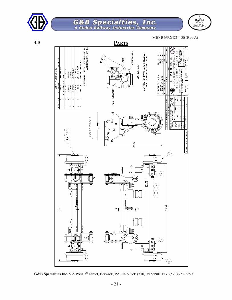
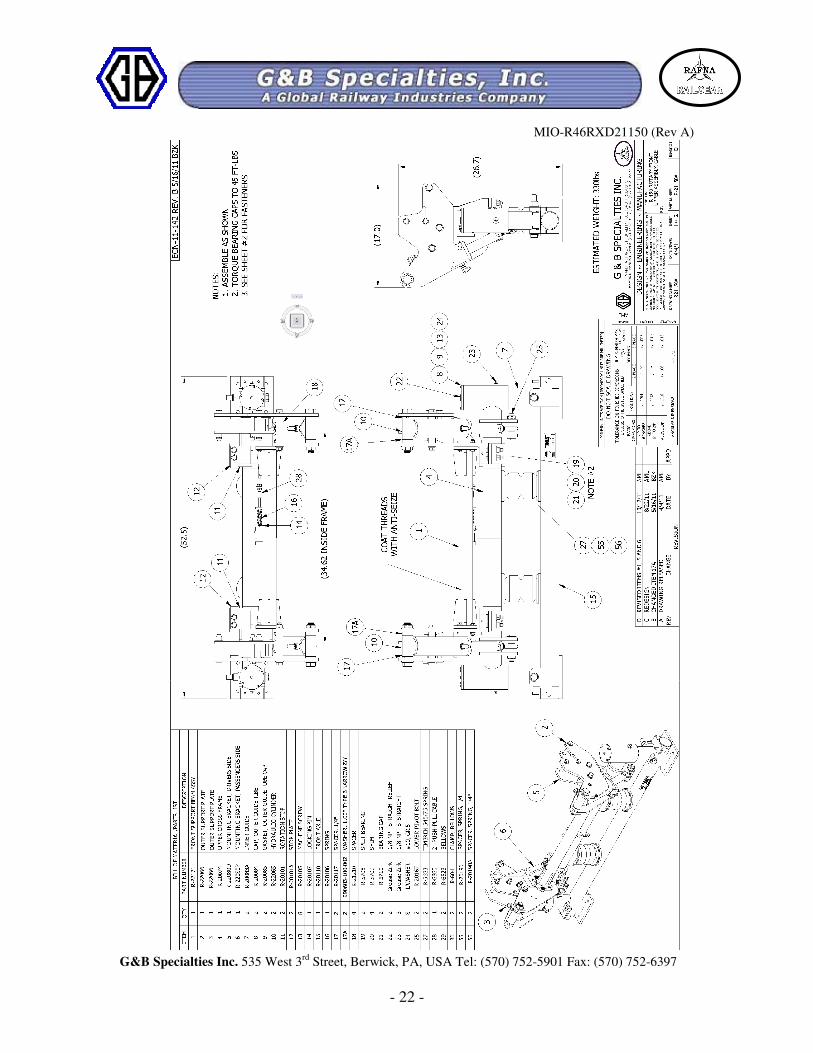
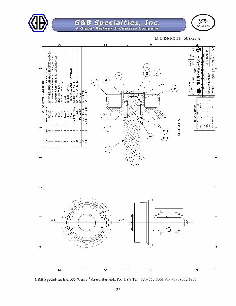
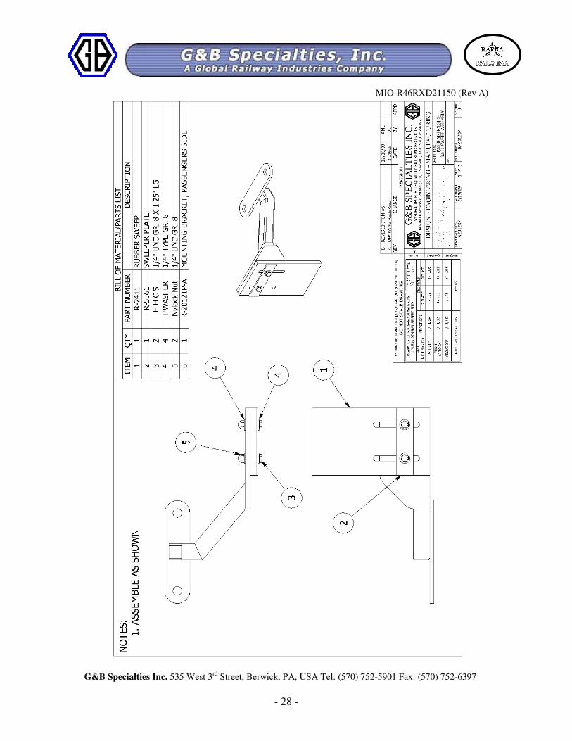
4.0 PARTS
MIO-R46RXD21150 (Rev A)
G&B Specialties Inc. 535 West 3rd
Street, Berwick, PA, USA Tel: (570) 752-5901 Fax: (570) 752-6397
- 22 -

MIO-R46RXD21150 (Rev A)
G&B Specialties Inc. 535 West 3rd
Street, Berwick, PA, USA Tel: (570) 752-5901 Fax: (570) 752-6397
- 23 -

MIO-R46RXD21150 (Rev A)
G&B Specialties Inc. 535 West 3rd
Street, Berwick, PA, USA Tel: (570) 752-5901 Fax: (570) 752-6397
- 24 -
MIO-R46RXD21150 (Rev A)
G&B Specialties Inc. 535 West 3rd
Street, Berwick, PA, USA Tel: (570) 752-5901 Fax: (570) 752-6397
- 25 -

MIO-R46RXD21150 (Rev A)
G&B Specialties Inc. 535 West 3rd
Street, Berwick, PA, USA Tel: (570) 752-5901 Fax: (570) 752-6397
- 26 -

MIO-R46RXD21150 (Rev A)
G&B Specialties Inc. 535 West 3rd
Street, Berwick, PA, USA Tel: (570) 752-5901 Fax: (570) 752-6397
- 27 -
MIO-R46RXD21150 (Rev A)
G&B Specialties Inc. 535 West 3rd
Street, Berwick, PA, USA Tel: (570) 752-5901 Fax: (570) 752-6397
- 28 -