Embed Size (px)
Citation preview

ROTARY MOTION CONTROL
Eclipse® Servomotor Brakes
Application & Selection Guide
Features
2
Cross-S
ectional D
rawings
4
Dim
ensions
5
Specifications
11
Solenoid Valve
14
AP
PE
ND
IX:
Definitions
15
Contact
Information
16
PATENTED
Courtesy of Steven Engineering, Inc. - (800) 258-9200 - [email protected] - www.stevenengineering.com

2
Tracing its roots back to 1902, Nexen's long history of innovation and quality show a legacy of advancing the motion control industry through its commitment to product development.
Continually testing and improving products as well as developing new technology, Nexen's contribution to the industry is now illustrated in the expanded Eclipse® line of servomotor brakes. With over 140 models in seven bore sizes, Nexen offers an off-the-shelf braking solution for any servo application. These spring-engaged, air released brakes eliminate the performance problems associated with electrical brakes for consistent, long lasting performance.
The Nexen Eclipse® Advantage
Easy Installation. Maintenance Free. Eclipse® Servo Brakes Simplify Excellence.
WASH-DOWN PROTECTIONSealed housings offer environmental protection and meets IP67 dust and waterproof standards. Optional nickel plating also available.
ZERO BACKLASHThe easy to install, keyless split-hub shaft collar prevents backlash for smooth stopping and precision holding.
LOW INERTIAOne-piece rotor/shaft assembly lowers inertia and eliminates spline for zero backlash.
COOL OPERATIONAir release disengagement adds no heat, providing cool operation and long life.
Standard electric brakes generate heat when disengaged, lowering the efficiency of the unit. The air-release design of the Eclipse® models requires no energy for operation, resulting in higher, more consistent torque capabilities.
SMOOTH TORQUE TRANSMISSIONDouble-taper facing locks down on the housing and rotor to create a zero-backlash torque transmission interface.
RUGGED STRENGTHOne piece, solid shaft increases torsional rigidity and overhung load capabilities.
From product selection to installation and maintenance, Nexen designed its Eclipse Servomotor Brakes with ease-of-use in mind.
SE
LEC
TIO
N
INS
TALL
ATIO
N
MA
INTE
NA
NC
EA variety of sizes, mounting configurations and torque offerings, make retrofits on existing machines quick and easy.
This vast array of flange options transforms what was once custom design into Eclipse® standard. No special ordering. No lengthy waiting. Eclipse® saves you time, consolidates resources, and lowers inventory costs.
The brake flange replicates the servo-motor flange, so no accommodations are needed. Simply slide the brake between your motor and gearbox and tighten the shaft collar.
Operators will appreciate the true pilot mounting and seamless integration with IEC or NEMA frame motors.
While field serviceable, the long facing life and lubrication-free operation of this line of servomotor brakes make it virtually maintenance-free.
Nexen brakes simplify machine maintenance by holding the load during motor change-outs, even in power-off situations.
Courtesy of Steven Engineering, Inc. - (800) 258-9200 - [email protected] - www.stevenengineering.com

3
Dependable Power Ensures SafetyWhen it comes to service factor, Nexen believes more is better. More torque and high brake stiffness mean operators and equipment are protected.
Strong enough to stall a servomotor in continuous torque mode, the high torque ratings on Eclipse® brakes provide fast response with a short stopping distance in emergency situations. In fact, Nexen's servomotor brakes deliver at least 20-50% more torque than competitive brakes.
Eclipse® Brakes offer at least 20-50%
more torque than competitive brakes.
Standard Electric Servomotor Brake
Nexen Eclipse®
Servomotor Brakes
Static Torque up to 125 Nm
limited torque capabilities
D y n a m i c S t o p p i n g
Prec is ion H o l d i n g
APPLICATIONS
Medical Devices
Food Production
Automotive Parts
Renewable Energy
Semiconductors
Printing
Paper Converting
CNC Machining
Packaging
Machine Tool
Robotics
Woodworking
Conveying
With fail-safe reliability, Eclipse®servomotor
brakes hold each joint securely to prevent any arm movement during power-off situations.
Able to repeatedly stop and hold in challenging cyclic operations, Nexen Servomotor Brakes also offer a safety feature to this robot: if a belt breaks,
the servomotor brake(s) instantly engage to hold the load securely.
Rectangular Robot
Articulating Arm
In emergency stopping situations, Eclipse® brakes stop the
load(s) quickly and safely with bidirectional braking capabilities.
Gantry Router
Courtesy of Steven Engineering, Inc. - (800) 258-9200 - [email protected] - www.stevenengineering.com

4
Cro
ss-S
ecti
on
al
Dra
win
gs
Eclipse® Brake Cross-Sectional Drawings
2 3
Friction Facing
O-ring Seals
Air Chamber
Output Shaft
Ball Bearing
PistonWave Spring
Clamping Collar
Input Flange
Air Input
Friction Facing
O-ring Seals
Air Chamber
Output Shaft
Ball Bearing
Piston
Spring Backing Plate
Compression Springs
Clamping Collar
Input Flange
Air Input
NOTE: Size 5 contains a single row, deep groove ball bearing. Sizes 2,3 and 4 contain a double row.
SIZES 7, 9, 11
SIZES 2, 3, 4, 5
Courtesy of Steven Engineering, Inc. - (800) 258-9200 - [email protected] - www.stevenengineering.com

5
Dim
ensio
ns
Servomotor Brake Approximate Dimensions (NEMA Square Flange Motors)
NEMA Square Flange NEMA Size 23 NEMA Size 34 NEMA Size 42
Nexen Model SBP-2 SBP-3 SBP-4
A Bore Diameter 0.25 0.312 0.375 0.375 0.5 0.5 0.625 0.625
B Bore Depth 1.43 1.46 2.2 2.5
C Pilot (female) 1.5 2.875 4.331 2.189
D Pilot Depth -- 0.11 -- 0.16 0.2 0.16 0.2 0.138 --
E-F Bolt Circle Diameter
2.625 3.346–4.280 4.950–5.904
G Flange Width 2.25 3.62 4.92
H Bolt Hole 10–24 0.28 0.49
J Length 2.77 3.06 4.23
K Quick Exhaust 1.99 2.6 2.6 3.62 2.3 3.2
L Shaft Diameter 0.25 0.312 0.375 0.5 0.5 0.625 0.625 0.625
M Shaft Length 1.25 1.25 1.2 1.2 1.18 1.5 2.063
N Pilot Extension 0.095 0.12 0.12 0.16 0.12 0.12 0.18
P Bolt Hole 0.197 0.233 0.39 0.375–16
Q Pilot (male) 1.5 2.875 2.187 4.5
R-S Bolt Circle Diameter
2.625 3.875–4.280 4.950–5.904 5.875
T Keyway none none 0.125 0.125 0.189 0.189
Product Number 964606 964611 964605 964729 964728 964722 964726 964833 964835
NOTE: Dimensions for NEMA brakes are shown in inches.
The following section contains the approximate dimensions for each size of Nexen's Eclipse® Servomotor Brakes. Always verify product information with the user manual when specifying a new brake into your application. Refer to www.nexengroup.com for user manuals, product dimensions and specifications.
mm[in]
32[1.2]
.125-27 NPT
H4 at 90°
ØE–F
ØA
K
C Q
D
BJ GM
N
L
ØT
ØR–S
45º Exaust Air
Eclipse® Dimensions
Courtesy of Steven Engineering, Inc. - (800) 258-9200 - [email protected] - www.stevenengineering.com

6
Servomotor Brake Approximate Dimensions (IEC Square Flange Motors: sizes 2 & 3)
Product Number
BORE DIA.
BORE DEPTH
PILOT(female)
PILOT DEPTH
BOLT CIRCLE DIAMETER
FLANGE WIDTH
BOLT HOLE LENGTH QUICK
EXHAUSTSHAFT
DIA.SHAFT
LENGTHPILOT EXT.
BOLT HOLE
PILOT(male)
BOLT CIRCLE DIAMETER KEYWAY
A B C D E-F G H J K L M N P Q R-S T
964721 10 37 80 5 90-109 92 7.0 77.7 65 10 30 3.0 7.0 80 100-109 3.0
964717 13 37 2.875" 4 85-109 92 7.0 77.7 65 13 30 3.0 5.9 2.875" 100-109 5
964713 14 37 50 5 95-109 92 7.0 77.7 65 14 30 3.0 7.0 50 95-109 5
964714 14 37 70 4 85-109 92 7.0 77.7 65 14 30 3.0 7.0 70 85-109 5
964709 14 37 80 5 90-109 92 7.0 77.7 65 14 30 3.0 7.0 80 100-109 5.0
964710 14 37 80 5 90-109 92 7.0 77.7 65 14 30 3.0 7.0 80 100-109 5.0
964724 14 40 80 8 90-109 92 7.0 80.7 65 14 30 3.0 7.0 80 100-109 5.0
964718 14 37 2.875" 4 85-109 92 7.0 77.7 65 14 30 3.0 5.9 2.875" 98-109 5.0
964725 14 37 60 4 85-115 92 7.0 77.7 65 14 30 3.0 5.9 2.875" 98-109 5.0
964727 14 37 80 5 90-109 92 7.0 77.7 65 14 30 3.0 7.0 80 100-109 5.0
964716 0.625" 37 80 5 90-109 92 7.0 77.7 65 0.625" 30 3.0 5.9 2.875" 98-109 .188"
964720 16 42 80 5 90-109 92 7.0 77.7 65 16 40 3.0 7.0 80 100-109 5.0
964712 16 42 80 5 90-109 92 7.0 77.7 65 16 40 3.0 7.0 70 90-109 5.0
964711 16 45 80 5 90-109 92 7.0 69.9 65 16 40 3.0 7.0 70 90-109 5.0
964715 16 42 80 5 90-109 92 7.0 77.7 65 16 40 3.0 7.0 80 100-109 5.0
964730 16 48 80 6 90-109 92 7.0 83.7 65 16 40 3.0 7.0 80 100-109 5.0
964732 19 51.6 80 5 90-109 92 7.0 77.7 65 16 40 3.0 7.0 80 100-109 5.0
964723 19 57 110 11 126-150 125/92 10.0 88.2 65 16 40 3.0 7.0 70 90-109 5.0
964719 19 40.7 2.875" 5 90-109 92 7.0 77.7 65 16 40 3.0 7.0 70 90-109 5.0
964733 19 51 80 5 90-109 92 7.0 84.2 65 19 40 3.0 7.0 80 100-109 6.0
Product Number
BORE DIA.
BORE DEPTH
PILOT(female)
PILOT DEPTH
BOLT CIRCLE DIAMETER
FLANGE WIDTH
BOLT HOLE LENGTH QUICK
EXHAUSTSHAFT
DIA.SHAFT
LENGTHPILOT EXT.
BOLT HOLE
PILOT(male)
BOLT CIRCLE DIAMETER KEYWAY
A B C D E-F G H J K L M N P Q R-S T
964610 9.0 35.9 40 2.4 63 57.2 10–24 70.4 50.6 9.0 20 2.4 0.205" 40 63 no key
964615 9.0 35.9 40 2.4 63 57.2 M4 70.4 50.6 9.0 20 2.4 0.205" 40 63 no key
964612 9.0 37 50 2.4 70 57.2 M5 70.4 50.6 9.0 25 2.4 0.250" 50 63 no key
964617 11.0 33.1 60 3.5 70-91.5 74.2 0.250" 74.5 57 11.0 23 1.5 6 60 75-91.5 4.0
964614 11.0 33.1 60 3.5 70-91.5 74.2 0.250" 74.5 57 14.0 30 1.5 6 60 75-91.5 5.0
964613 14.0 33.1 50 3.5 63-91.5 74.2 0.250" 74.5 56 14.0 30 1.5 6 50 70-91.5 5.0
All dimensions shown in millimeters unless otherwise specified.
Dim
ensi
ons
mm[in]
Size 2
Size 3
32[1.2]
.125-27 NPT
H4 at 90°
ØE–F
ØA
K
C Q
D
BJ GM
N
L
ØT
ØR–S
45º Exaust Air
Courtesy of Steven Engineering, Inc. - (800) 258-9200 - [email protected] - www.stevenengineering.com

7
Servomotor Brake Approximate Dimensions (IEC Square Flange Motors: size 4)
Product Number
BORE DIA.
BORE DEPTH
PILOT(female)
PILOT DEPTH
BOLT CIRCLE DIAMETER
FLANGE WIDTH
BOLT HOLE LENGTH QUICK
EXHAUSTSHAFT
DIA.SHAFT
LENGTHPILOT EXT.
BOLT HOLE
PILOT(male)
BOLT CIRCLE DIAMETER KEYWAY
A B C D E-F G H J K L M N P Q R-S T
964865 14 36 80 3.5 115-150 125 10.0 105.7 82 14 20.5 2.3 10.0 80 115-150 none
964867 14 63 95 6 115-150 125 10.0 113.2 82 14 36 2.3 10.0 95 115-150 5.0
964824 14 55.5 80 3.5 115-150 125 10.0 105.7 82 14 30 2.3 10.0 80 115-150 5.0
964852 16 56.3 110 3.5 126-150 125 10.0 105.7 82 16 40 2.3 10.0 110 130-150 5.0
964834 0.625" 56.1 2.500” 3.5 127-150 125 10.0 107.4 82 0.625" 2.000” 2.5 10.0 2.500” 127-150 0.188”
964826 0.625" 56.2 4.500” 3.5 5.875" 125 0.405” 106.5 82 19 40 2.3 10.0 110 130-150 6.0
964818 19 55.5 95 3.5 115-150 125 10.0 105.7 82 19 40 2.3 10.0 95 115-150 6.0
964823 19 55.5 95 3.5 115-150 125 10.0 105.7 82 19 40 2.3 10.0 95 115-150 6.0
964843 19 55.5 95 3.5 115-150 125 10.0 105.7 82 19 40 2.3 10.0 96 115-150 6.0
964866 19 55.6 110 3.5 126-150 125 10.0 106.5 82 19 70 2.3 10.0 110 130-150 6.0
964864 19 55.6 110 3.5 126-150 125 10.0 106.5 82 19 70 2.3 10.0 110 130-150 6.0
964826 0.625" 56.3 4.500” 3.5 5.875" 125 0.405” 106.5 82 19 40 2.3 10.0 110 130-150 6.0
964837 19 56.3 110 3.5 126-150 125 10.0 106.5 82 19 40 2.3 10.0 110 130-150 6.0
964814 19 55.5 110 3.5 126-150 125 10.0 106.5 82 19 50 2.3 10.0 110 130-150 6.0
964819 19 55.5 110 3.5 126-150 125 10.0 106.5 82 19 50 2.3 10.0 110 130-150 6.0
964832 19 60.5 95 3.5 115-150 125 10.0 105.7 82 19 55 2.3 10.0 95 115-150 6.0
964844 19 61.3 110 7 126-150 125 10.0 106.5 82 19 55 2.3 10.0 110 130-150 6.0
964856 19 64.5 110 16 126-150 125 10.0 115.5 82 19 50 2.3 10.0 110 130-150 6.0
964838 19 60.5 95 3.5 115-150 125 10.0 105.7 82 20 62 2.3 10.0 95 115-130 none
964849 19 60.5 95 3.5 115 125/150 .375-16 105.7 95 24 50 2.3 10.0 130 165-186 8.0
964851 19 70.3 110 16 126-150 125 10.0 115.5 82 24 50 2.3 10.0 110 130-150 8.0
964839 19 55.6 95 3.5 115-150 125 10.0 104.8 82 0.625" 2.063” 4.1 .375-16 4.500” 5.875" 0.188”
964816 19 42.9 95 3 126-150 125 10.0 104 82 0.875” 2.125” 4.1 .375-16 4.500” 5.875” 0.188”
964820 22 55.5 110 3.5 126-150 125 10.0 105.6 82 0.625" 2.063" 4.1 .375-16 4.500” 5.875” 0.188”
964821 22 67.1 110 3.5 126-150 125 10.0 99.2 82 22 50 2.3 10.0 110 130-150 6.0
964822 22 73.5 110 6.5 145 125 9.0 124.5 79 22 58 6.0 10.0 110 130-150 6.0
964836 24 56.5 110 3.5 126-150 125 10.0 105.6 82 0.875” 2.125” 4.1 .375-16 4.500” 5.875” 0.188”
964815 24 55.9 110 4 150-186 150/125 12.0 105 82 0.875” 2.125” 4.1 .375-16 4.500” 5.875” 0.188”
964817 24 55.5 110 3.5 126-150 125 10.0 106.5 82 24 50 2.3 10 110 130-150 0.188”
964851 19 70.3 110 16 126-150 125 10.0 115.5 82 24 50 2.3 10.0 110 130-150 8.0
964842 28 67.1 110 7 126-150 125 10.0 106.5 82 28 60 2.3 10.0 110 130-150 none
964848 24 59 110 7 126-150 125 10.0 106.5 82 24 50 2.3 10.0 110 130-150 8.0
964853 24 55.5 110 3.5 126-150 125 10.0 106.5 82 19 35 2.3 10.0 110 130-150 6.0
964830 24 54.7 95 3.5 115-150 125 10.0 105.7 82 24 45 2.3 7.0 95 115-150 8.0
964825 24 54.7 95 3.5 115-150 125 10.0 105.7 82 24 50 2.3 10.0 95 115-150 8.0
964828 24 55.5 110 3.5 126-150 125 10.0 106.5 95 24 50 2.3 10.0 110 130-150 8.0
964829 24 55.5 110 3.5 126-150 125 10.0 106.5 82 24 50 2.3 10.0 110 130-150 8.0
964860 24 58.1 110 3.5 126-150 125 10.0 106.5 82 24 50 2.3 10.0 110 130-150 8.0
964855 28 85.7 110 7 126-150 125 10.0 125 82 28 60 2.3 10.0 110 130-150 none
All dimensions shown in millimeters unless otherwise specified.
Dim
ensions
mm[in]
Size 4
32[1.2]
.125-27 NPT
H4 at 90°
ØE–F
ØA
K
C Q
D
BJ GM
N
L
ØT
ØR–S
45º Exaust Air
Courtesy of Steven Engineering, Inc. - (800) 258-9200 - [email protected] - www.stevenengineering.com

8
Dim
ensi
ons
Servomotor Brake Approximate Dimensions (IEC Square Flange Motors: size 5)
Size 5
All dimensions shown in millimeters unless otherwise specified.
mm[in]
Product Number
BORE DIA.
BORE DEPTH
PILOT(female)
PILOT DEPTH
BOLT CIRCLE DIAMETER
FLANGE WIDTH
BOLT HOLE LENGTH QUICK
EXHAUSTSHAFT
DIA.SHAFT
LENGTHPILOT EXT.
BOLT HOLE
PILOT (male)
BOLT CIRCLE DIAMETER KEYWAY
A B C D E-F G H J K L M N P Q R-S T
964933 24 63 110 6.2 130 150.5 M8 132.5 95 24 50 2.4 12.0 110 165-186 8.0
964934 24 63 110 6.2 145 150.4 M8 132.5 95 24 50 2.4 12.0 110 165-186 8.0
964909 24 58 110 6.2 150-186 150.4 12.0 132.5 95 24 50 2.4 12.0 110 165-186 8.0
964913 24 58 110 6.2 150-186 150.4 12.0 132.5 95 24 50 2.4 12.0 110 165-186 8.0
964907 24 58 130 6.2 150-186 150.4 12.0 132.5 95 24 50 2.4 12.0 130 165-186 8.0
964908 24 58 130 6.2 150-186 150.4 12.0 132.5 95 24 50 2.4 12.0 130 165-186 8.0
964930 24/kwy 66.7 110 6.2 150-186 150.4 12.0 132.5 95 24 50 2.4 12.0 110 165-186 8.0
964912 24 66.7 130 6.2 150-186 150.4 12.0 132.5 95 24 50 2.4 12.0 130 165-186 8.0
964916 24 64 130 6.2 150-186 150.4 12.0 131.9 95 0. 875” 2.125” 4.1 .375-16 4.500” 5.875" 0.188"
964923 24 58 130 6.2 150-186 150.4 12.0 131.9 95 1.062” 1.950” 4.1 .375-16 4.500” 5.875" 0.250"
964917 1.125” 60.5 4.500” 6.2 150-186 150.4 12.0 132.5 95 24 50 2.4 12.0 110 165-186 8.0
964929 28 66.7 130 6.2 150-186 150.4 12.0 132.5 95 24 50 2.4 12.0 130 165-186 8.0
964915 28 66.7 130 6.2 150-186 150.4 12.0 132.5 95 28 60 2.4 12.0 130 165-186 8.0
964920 28 66.7 130 6.2 150-186 150.4 12.0 132.5 95 28 60 2.4 12.0 130 165-186 8.0
964928 28 66.7 130 6.2 150-186 150.4 12.0 131.9 95 1.062” 1.950” 4.1 .375-16 4.500” 5.875" 0.250"
964932 28 71.7 130 6.2 150-186 150.4 12.0 132.5 95 28 60 2.4 12.0 130 165-186 8.0
964918 32 58 130 6.2 150-186 150.4 12.0 132.5 95 32 54 2.4 12.0 130 165-186 10.0
964931 32 58 130 6.2 150-186 150.4 12.0 132.5 95 32 54 2.4 12.0 130 165-186 10.0
964925 32 82 130 6.2 150-186 150.4 12.0 132.5 95 24 50 2.4 12.0 130 165-186 none
964906 32 65.7 130 4.0 215178/
150.415.0 140.5 95 0. 875” 2.125” 4.1 .375-16 4.500” 5.875" 0.188"
964921 32 75.2 130 4.0 215178/
150.415.0 141 95 32 60 2.4 12.0 130 165-186 10.0
964919 32 66.7 130 6.2 150-186 150.4 12.0 132.5 95 32 60 2.4 12.0 130 165-186 10.0
964937 32/kwy 83 130 6.2 150-186 150.4 12.0 148.5 95 32 80 2.4 12.0 130 165-186 10.0
32[1.2]
.125-27 NPT
H4 at 90°
ØE–F
ØA
K
C Q
D
BJ GM
N
L
ØT
ØR–S
45º Exaust Air
Courtesy of Steven Engineering, Inc. - (800) 258-9200 - [email protected] - www.stevenengineering.com

9
Dim
ensio
ns
Servomotor Brake Approximate Dimensions (IEC Square Flange Motors: size 7)
Size 7
All dimensions shown in millimeters unless otherwise specified.
mm[in]
Product Number
BORE DIA.
BORE DEPTH
PILOT (female)
PILOT DEPTH
BOLT CIRCLE DIAMETER
FLANGE WIDTH
BOLT HOLE LENGTH QUICK
EXHAUSTSHAFT
DIA.SHAFT
LENGTHPILOT EXT.
BOLT HOLE
PILOT (male)
BOLT CIRCLE DIAMETER KEYWAY
A B C D E-F G H J K L M N P Q R-S T
965008 24 83.2 130 6.1 165 192 M10 102.3 113 24 50 3.5 12.0 130 180 8.0
965010 32 83.2 130 6.1 165 192 M10 102.3 113 32 60 3.5 15.0 130 215 10.0
965001 32 83.2 180 6.1 215 192 15.0 102.3 113 32 60 3.5 15.0 180 215 10.0
965006 32 83.2 180 6.1 215 192 15.0 102.3 113 32 60 3.5 15.0 180 215 10.0
965004 32 83.2 130 6.1 215 192 15.0 102.3 113 32 60 3.5 15.0 130 215 10.0
965014 32 82 130 6.1 165 174 .438-14 102.3 105 1.250" 80 3.2 13.5 4.500” 200 0.250"
965015 1.375" 88.2 4.500" 6.1 200 174 .500-13 102.3 105 1.375” 3.875” 3.2 13.5 4.500” 200 0.314"
965011 1.375" 88.2 4.500" 6.1 200 174 .500-13 102.3 105 1.375” 3.875” 3.2 13.5 4.500” 200 0.314"
965017 1.375" 84.6 4.500" 6.1 7.750" 174 .375-16 102.3 105 1.375” 66.5 3.2 .375-16 4.500” 7.750" 0.314"
965005 35 88.2 4.500" 6.1 200 174 M12 102.3 104 35 79 3.2 13.5 4.500” 200 10.0
965007 32 84.9 180 6.1 215 192 15.0 102.3 NA 1.375” 3.37" 0.250" .500” 8.500” 7.250" 0.314"
965012 32 83.2 130 6.1 215 192 15.0 102.3 132 1.125" 2.89" 0.250" .500-13 8.500” 7.250" 0.250"
965014 32 82 130 6.1 165 174 .438-14 102.3 105 1.250" 80 3.2 13.5 4.500” 200 0.250"
965013 32 83.2 130 6.1 215 192 15.0 102.3 113 32 60 3.5 15.0 130 215 10.0
965000 32 83.2 130 6.1 215 192 15.0 102.3 113 32 60 3.5 15.0 130 215 10.0
965026 32/kwy 82.1 130 6.1 215 192 .500-13 102.3 113 35 95 3.5 .500-13 130 215 10.0
965003 35 88.2 4.500" 6.1 200 174 M12 102.3 104 35 79 3.2 13.5 4.500” 200 10.0
965002 35 88.2 4.500" 6.1 200 192 13.0 102.3 113 35 80 3.5 13.0 4.500” 200 10.0
965019 38 83.2 180 6.1 215 192 15.0 102.3 113 38 80 3.5 15.0 180 215 12.0
965009 42 114.1 4.500" 5.0 200 174 12.8 128.2 104 35 79 3.2 13.5 4.500” 200 10.0
965016 42 114.1 4.500" 5.0 200 174 12.8 128.2 104 42 113 3.2 13.5 4.500” 200 12.0
965021 1.188" 88.2 4.500" 6.1 200192/174
13.0 102.3 104 35 79 3.2 13.5 4.500” 200 10.0
965020 42 114.1 4.500" 5.0 200 174 12.8 128.2 104 42 113 3.2 13.5 4.500” 200 12.0
R—S
G
C
K
A
E-F
H (4 at 90º)32
[1.2] .125−NPT
D N
B
J M
LQ
Quick Exhaust Valve Exhaust Air
(4 at 90º) P
T
Courtesy of Steven Engineering, Inc. - (800) 258-9200 - [email protected] - www.stevenengineering.com

10
Dim
ensi
ons
Servomotor Brake Approximate Dimensions (IEC Square Flange Motors: sizes 9 & 11)
Size 11
Size 9
All dimensions shown in millimeters unless otherwise specified.
mm[in]
Product Number
BORE DIA.
BORE DEPTH
PILOT (female)
PILOT DEPTH
BOLT CIRCLE DIAMETER
FLANGE WIDTH
BOLT HOLE LENGTH QUICK
EXHAUSTSHAFT
DIA.SHAFT
LENGTHPILOT EXT.
BOLT HOLE
PILOT (male)
BOLT CIRCLE DIAMETER KEYWAY
A B C D E-F G H J K L M N P Q R-S T
965100 38 83.2 180 4.1 215 214 13.0 102.3 124 38 60 3.5 13.0 180 215 12.0
965110 38 83.2 180 4.1 215 214 13.0 102.3 124 38 60 3.5 13.0 180 215 10.0
965111 38 83.2 180 4.1 215 214 13.0 102.3 124 38 60 3.5 13.0 180 215 10.0
965102 38 83.2 180 4.1 215 214 13.0 102.3 124 38 60 3.5 13.0 180 215 12.0
965104 38 83.2 180 4.1 215 214 13.0 102.3 124 38 60 3.5 13.0 180 215 12.0
965103 38 83.2 180 4.1 215 214 M14 102.3 124 38 80 3.5 11.0 180 215 12.0
965107 38 83.2 180 4.1 215 214 13.0 102.3 124 38 80 3.5 13.0 180 215 none
965101 38 83.2 180 5.0 215 214 M12 102.3 124 1.375" 60 3.5 13.0 180 215 none
965208 38 83.2 180 5.0 215 214 M12 102.3 124 38 80 3.5 14.0 180 215 12.0
965105 42 117.1 200 5.0 235220/214
13.5 136.2 124 42 116 3.5 13.5 200 235 12.0
965106 55 117.1 200 5.0 235220/214
13.5 154.5 124 42 80.9 3.5 14.0 180 8.434" 12.0
Product Number
BORE DIA.
BORE DEPTH
PILOT (female)
PILOT DEPTH
BOLT CIRCLE DIAMETER
FLANGE WIDTH
BOLT HOLE LENGTH QUICK
EXHAUSTSHAFT
DIA.SHAFT
LENGTHPILOT EXT.
BOLT HOLE
PILOT (male)
BOLT CIRCLE DIAMETER KEYWAY
A B C D E-F G H J K L M N P Q R-S T
965201 35 92.1 230 9.1 265 262.9 M12 123.3 158 35 92 5.0 14.0 230 265 None
965202 42 110.1 230 5 265 262.9 12.8 143.3 148 42 92 5.0 14.0 230 265 12.0
965204 42/kyw 106.56 250 9.1 300 262.9 .625-11 123.3 148 45 100 5.0 .625-11 250 300 14.0
965200 48 91.56 250 9.1 300 262.9 15.0 123.3 148 48 60 5.0 15.0 250 300 14.0
965205 48 91.56 250 9.1 300 262.9 15.0 123.3 148 48 60 5.0 15.0 250 300 14.0
965203 48 91.56 250 9.1 300 262.9 15.0 123.3 148 48 82 5.0 15.0 250 300 14.0
R—S
G
C
K
A
E-F
H (4 at 90º)32
[1.2] .125−NPT
D N
B
J M
LQ
Quick Exhaust Valve Exhaust Air
(4 at 90º) P
T
Courtesy of Steven Engineering, Inc. - (800) 258-9200 - [email protected] - www.stevenengineering.com

11
Specifications
Eclipse® Performance
Product Number
Static Torque
Transmittable Torque
Torsional Rigidity
Engage Time
Release Time Max
RPM
Overhung Load
Shaft Inertia
Minimum Release Pressure
Nm Nm Nm/rad msec msec Newtons kg•m2 bar
Size 2964610 2.3 2.3 1,000 8 92 10,000
Not Recommended
0.00002 5.5
964615 2.3 2.3 1,000 8 92 10,000 0.00002 5.5
964612 2.3 2.3 1,000 8 92 10,000 0.00002 5.5
964617 2.3 2.3 2,700 8 92 10,000 845 0.00002 5.5
964614 2.3 2.3 2,700 8 92 10,000 845 0.00002 5.5
964613 2.3 2.3 3,700 8 92 10,000 845 0.00002 5.5
Size 3964721 5.0 7.9 1,800 12 75 10,000 400 0.00005 3.4
964717 7.9 7.9 3,900 12 75 10,000 1,070 0.00005 5.5
964713 5.0 7.9 4,500 12 75 10,000 1,070 0.00005 3.4
964714 7.9 7.9 4,500 12 75 10,000 1,070 0.00005 5.5
964709 7.9 7.9 4,500 12 75 10,000 1,070 0.00005 5.5
964710 5.0 7.9 4,500 12 75 10,000 1,070 0.00005 3.4
964724 5.0 7.9 4,500 12 75 10,000 1,070 0.00005 3.4
964718 7.9 7.9 4,500 12 75 10,000 1,070 0.00005 5.5
964725 7.9 7.9 4,500 12 75 10,000 1,070 0.00005 5.5
964727 7.9 7.9 4,500 12 75 10,000 1,070 0.00005 5.5
964716 7.9 7.9 5,700 12 75 10,000 1,070 0.00005 5.5
964720 5.0 7.9 5,700 12 75 10,000 1,070 0.00005 3.4
964712 7.9 7.9 5,700 12 75 10,000 1,070 0.00005 5.5
964711 7.9 7.9 5,700 12 75 10,000 1,070 0.00005 5.5
964715 7.9 7.9 5,700 12 75 10,000 1,070 0.00005 5.5
964730 7.9 7.9 5,700 12 75 10,000 1,070 0.00005 5.5
964732 7.9 7.9 7,200 12 75 10,000 1,070 0.00005 5.5
964723 5.0 7.9 7,200 12 75 10,000 1,070 0.00005 3.4
964719 7.9 7.9 7,200 12 75 10,000 1,070 0.00005 5.5
964733 8.0 8.0 11,500 12 75 10,000 1,070 0.00005 5.5
Product Number
Static Torque
Transmittable Torque
Torsional Rigidity
Engage Time
Release Time Max
RPM
Overhung Load
Shaft Inertia
Minimum Release Pressure
in-lbf in-lbf lbf-ft/rad msec msec lbf lbf-ft2 psi
Nexen Model SBP-2 for NEMA 23964606 20 20 1,000 8 92 10,000
Not Recommended
0.0005 80
964611 20 20 1,000 8 92 10,000 0.0005 80
964605 20 20 1,000 8 92 10,000 0.0005 80
Nexen Model SBP-3 for NEMA 34964729 70 70 3,900 12 75 10,000 240 0.0012 80
964728 70 70 3,900 12 75 10,000 240 0.0012 80
964722 70 70 3,900 12 75 10,000 240 0.0012 80
964726 70 70 5,700 12 75 10,000 240 0.0012 80
Nexen Model SBP-4 for NEMA 42964833 200 200 6,200 50 80 10,000 210 0.0074 80
964835 200 200 6,200 50 80 10,000 210 0.0074 80
Servomotor Brake Specifications
NEMA Square Flange Compatible
Metric Square Flange Sizes
See appendix for specification definitions.
Eclipse® Servomotor Brakes Deliver: High Torque • High Torsional Rigidity • Low Inertia
Courtesy of Steven Engineering, Inc. - (800) 258-9200 - [email protected] - www.stevenengineering.com

12
Servomotor Brake Specifications (metric size 4)
Spe
cific
atio
ns
Product Number
Static Torque
Transmittable Torque
Torsional Rigidity
Engage Time
Release Time Max
RPM
Overhung Load
Shaft Inertia
Minimum Release Pressure
Nm Nm Nm/rad msec msec Newtons kg•m2 bar
Size 4964865 22 22 4,300 50 80 10,000 845 0.00027 5.5
964867 22 22 4,300 50 80 10,000 845 0.00027 5.5
964824 22 22 4,300 50 80 10,000 845 0.00027 5.5
964852 22 22 6,200 50 80 10,000 1,423 0.00027 5.5
964834 22 22 6,200 50 80 10,000 934 0.00027 5.5
964826 22 22 6,200 50 80 10,000 2,334 0.00027 5.5
964818 22 22 11,800 50 80 10,000 2,334 0.00031 5.5
964823 14.1 22 11,800 50 80 10,000 2,334 0.00031 3.4
964843 22.6 22 11,800 50 80 10,000 2,334 0.00031 5.5
964866 22.6 22 11,800 50 80 10,000 1,423 0.00031 5.5
964864 14.1 22 11,800 50 80 10,000 1,423 0.00031 3.4
964826 22.6 22 11,800 50 80 10,000 2,334 0.00031 5.5
964837 22.6 22 11,800 50 80 10,000 2,334 0.00031 5.5
964814 22.6 22 11,800 50 80 10,000 1,780 0.00031 5.5
964819 14.1 22 11,800 50 80 10,000 1,780 0.00031 3.4
964832 22.6 22 11,800 50 80 10,000 1,780 0.00031 5.5
964844 22.6 22 11,800 50 80 10,000 1,780 0.00031 5.5
964856 22.6 22 11,800 50 80 10,000 1,780 0.00031 5.5
964838 22.6 22 11,800 50 80 10,000 1,780 0.00031 5.5
964849 22.6 22 20,700 50 80 10,000 2,334 0.00031 5.5
964851 22.6 22 20,700 50 80 10,000 2,334 0.00031 5.5
964839 22.6 22 11,800 50 80 10,000 934 0.00031 5.5
964816 22.6 22 11,800 50 80 10,000 2,334 0.00031 5.5
964820 22.6 22 16,300 50 80 10,000 934 0.00031 5.5
964821 22.6 22 16,300 50 80 10,000 2,334 0.00031 5.5
964822 14.1 22 16,300 50 80 10,000 2,334 0.00031 3.4
964836 22.6 22 20,700 50 80 10,000 2,334 0.00031 5.5
964815 22.6 22 20,700 50 80 10,000 2,334 0.00031 5.5
964817 22.6 22 20,700 50 80 10,000 2,334 0.00031 5.5
964851 22.6 22 20,700 50 80 10,000 2,334 0.00031 5.5
964842 22.6 22 37,000 50 80 10,000 2,334 0.00041 5.5
964848 22.6 22 20,700 50 80 10,000 2,334 0.00031 5.5
964853 22.6 22 20,700 50 80 10,000 2,334 0.00031 5.5
964830 22.6 22 20,700 50 80 10,000 2,334 0.00031 5.5
964825 22.6 22 20,700 50 80 10,000 2,334 0.00031 5.5
964828 22.6 22 20,700 50 80 10,000 2,334 0.00031 5.5
964829 14.1 22 20,700 50 80 10,000 2,334 0.00031 3.4
964860 22.6 22 20,700 50 80 10,000 2,334 0.00031 5.5
964855 22.6 22 37,000 50 80 10,000 2,334 0.00041 5.5
See appendix for specification definitions.
Courtesy of Steven Engineering, Inc. - (800) 258-9200 - [email protected] - www.stevenengineering.com
13
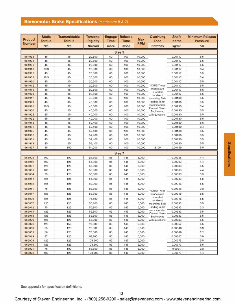
Servomotor Brake Specifications (metric size 5 & 7)
Specifications
Product Number
Static Torque
Transmittable Torque
Torsional Rigidity
Engage Time
Release Time Max
RPM
Overhung Load
Shaft Inertia
Minimum Release Pressure
Nm Nm Nm/rad msec msec Newtons kg•m2 bar
Size 5964933 45 45 20,600 60 100 10,000
NOTE: These models are intended for direct
mounting. Side loading is not
recommended. Consult Nexen
Engineering with questions.
0.00117 5.5
964934 45 45 20,600 60 100 10,000 0.00117 5.5
964909 45 45 20,600 60 100 10,000 0.00117 5.5
964913 28.3 45 20,600 60 100 10,000 0.00117 3.4
964907 45 45 20,600 60 100 10,000 0.00117 5.5
964908 28.3 45 20,600 60 100 10,000 0.00117 3.4
964930 45 45 20,600 60 100 10,000 0.00117 5.5
964912 45 45 20,600 60 100 10,000 0.00117 5.5
964916 45 45 20,600 60 100 10,000 0.00117 5.5
964923 45 45 20,600 60 100 10,000 0.00117 5.5
964917 45 45 40,000 60 100 10,000 0.00130 5.5
964929 45 45 40,000 60 100 10,000 0.00130 5.5
964915 28.3 45 40,000 60 100 10,000 0.00130 3.4
964920 45 45 40,000 60 100 10,000 0.00130 5.5
964928 45 45 40,000 60 100 10,000 0.00130 5.5
964932 45 45 40,000 60 100 10,000 0.00130 5.5
964918 45 45 52,400 60 100 10,000 0.00130 5.5
964931 45 45 52,400 60 100 10,000 0.00130 3.4
964925 45 45 52,400 60 100 10,000 0.00130 5.5
964906 45 45 52,400 60 100 10,000 0.00130 5.5
964921 45 45 52,400 60 100 10,000 0.00130 5.5
964919 45 45 52,400 60 100 10,000 0.00130 5.5
964937 45 150 54,200 60 100 10,000 3100 0.00159 5.5
Size 7965008 100 100 24,600 85 145 5,000
NOTE: These models are intended for direct
mounting. Side loading is not
recommended. Consult Nexen
Engineering with questions.
0.00325 4.4
965010 100 125 55,300 85 145 5,000 0.00333 4.4
965001 125 125 55,300 85 145 5,000 0.00333 5.5
965006 100 125 55,300 85 145 5,000 0.00333 4.4
965004 75 125 55,300 85 145 5,000 0.00333 3.3
965014 125 125 55,300 85 145 5,000 0.00333 5.5
965015 125 125 83,300 85 145 5,000 0.00346 5.5
965011 75 125 83,300 85 145 5,000 0.00346 3.3
965017 125 125 83,300 85 145 5,000 0.00346 5.5
965005 125 125 76,500 85 145 5,000 0.00346 5.5
965007 125 125 55,300 85 145 5,000 0.00333 5.5
965012 75 125 55,300 85 145 5,000 0.00333 3.3
965014 125 125 55,300 85 145 5,000 0.00333 5.5
965013 125 125 55,300 85 145 5,000 0.00333 5.5
965000 125 125 55,300 85 145 5,000 0.00333 5.5
965026 125 150 76,500 85 145 5,000 0.00352 5.5
965003 75 125 76,500 85 145 5,000 0.00346 3.3
965002 50 125 76,500 85 145 5,000 0.00346 2.2
965019 87 125 98,700 85 145 5,000 0.00362 3.9
965009 125 125 108,600 85 145 5,000 0.00379 5.5
965016 125 125 108,600 85 145 5,000 0.00379 5.5
965021 75 100 65,800 85 145 5,000 0.0034 3.3
965020 100 125 108,600 85 145 5,000 0.00379 4.4
See appendix for specification definitions.
Courtesy of Steven Engineering, Inc. - (800) 258-9200 - [email protected] - www.stevenengineering.com

14
Spe
cific
atio
nsS
olen
oid
Valv
e
Product Number
Static Torque
Transmittable Torque
Torsional Rigidity
Engage Time
Release Time Max
RPM
Overhung Load
Shaft Inertia
Minimum Release Pressure
Nm Nm Nm/rad msec msec Newtons kg•m2 bar
Size 9965100 125 125 114,000 85 145 5,000
NOTE: These models are intended for direct
mounting. Side loading is not
recommended. Consult Nexen
Engineering with questions.
0.00362 5.5
965110 125 125 114,000 85 145 5,000 0.00362 5.5
965111 50 125 114,000 85 145 5,000 0.00362 2.2
965102 75 125 114,000 85 145 5,000 0.00362 3.3
965104 100 125 114,000 85 145 5,000 0.00362 4.4
965103 125 125 97,900 85 145 5,000 0.00362 5.5
965107 125 125 97,900 85 145 5,000 0.00362 5.5
965101 100 125 97,900 85 145 5,000 0.00362 4.4
965208 100 125 97,900 85 145 5,000 0.00362 4.4
965105 125 125 119,000 85 145 5,000 0.00379 5.5
965106 125 125 188,000 85 145 5,000 0.00554 5.5
Size 11965201 75 125 63,600 85 145 5,000
NOTE: Intended for direct
mounting. Side loading is not
recommended.
0.00346 3.3
965202 75 125 156,000 85 145 5,000 0.00379 3.3
965204 125 125 156,000 85 145 5,000 0.00379 5.5
965200 125 125 216,000 85 145 5,000 0.00404 5.5
965205 100 125 216,000 85 145 5,000 0.00404 4.4
965203 125 125 216,000 85 145 5,000 0.00411 5.5
Servomotor Brake Specifications (metric size 9 & 11)
Nexen's optional solenoid valve offers machine operators additional safety and peace of mind by allowing users to see at a glance whether or not the brake is disengaged. The manual override button provides an easy option for manual brake disengagement.
Nexen's solenoid valve mounts easily on any Eclipse® servomotor brake and operates using standard 80 PSIG compressed air and 24VDC controls.
• Visual Disengagement Indication• Manual Disengagement Button• Simple Connections: - 24VDC control - 80 PSIG shop air
To Brake
Air Supply Tube Fitting
Exhaust Silencer
Manual Override
Lead Wires3 ft. cable
1/8 NPT
Optional Solenoid Valve
See appendix for specification definitions.
Product Number: 964650
Courtesy of Steven Engineering, Inc. - (800) 258-9200 - [email protected] - www.stevenengineering.com

15
Appendix: Definitions
BACKLASHBecause zero backlash is impossible to measure, industry standard maintains that anything under 3.2 microns is considered zero.
The Eclipse® line of servomotor brakes have two design features that facilitate backlash-free performance. Both the keyless, split-hub clamping collar and the one piece rotor/shaft work to create a backlash free environment. The unique rotor/shaft actually lowers inertia and minimizes moving parts.
CORROSION RESISTANCENexen offers various corrosion countermeasures that include stainless steel and various surface treatments or coatings. Nexen will convey all material and coating specifications, but it is up to the customer to determine application suitability based on this information and/or thorough sample testing. Nexen makes no corrosion resistance claims for specific applications.
TRANSMITTABLE TORQUETransmittable torque is the maximum amount of torque that can be passed from a motor through the brake and into a gearbox or other output. Transmittable torque accounts for clamp-collar holding force and output shaft strength.
IP67 DUST & WATERPROOF STANDARDSThis international rating was developed to provide machine builders with standards by which to properly select products to operate in specific conditions. Nexen's Eclipse® line of Servomotor Brakes are completely enclosed and offer highest standard of protection against dust and water. They have been independently tested to withstand full immersion in water for up to 30 minutes at a depth of up to 1 meter and can withstand even the dirtiest environments with no degradation on efficiency, performance or life of the brake.
Ap
pen
dix
LUBRICATION FREE OPERATIONOperating without lubrication can be beneficial in food, pharmaceutical, clean room, and other applications where the grease could contaminate the environment, or applications with high levels environmental contaminates that would be attracted to the grease and accelerate the wear rate.
OVERHUNG LOAD (also called Side Loading)In overhung load applications the force of the load is applied to the shaft beyond the support point and is perpendicular to the shaft. Nexen ratings assume the load is applied at the shaft extension midpoint. Not all brakes are suitable for overhung loads. Refer to product specifications to determine suitability.
TORSIONAL RIGIDITYNexen Eclipse® Servomotor Brakes offer high torsional rigidity, meaning they can withstand a great amount of twisting force without it affecting performance. High torsional rigidity is beneficial in any system where precision positioning is required.
Courtesy of Steven Engineering, Inc. - (800) 258-9200 - [email protected] - www.stevenengineering.com

16
ISO 9001 Certified
Nexen has sales offices throughout the United States, Europe, Japan, and Australia.
www.nexengroup.com
In accordance with Nexen’s established policy of constant product improvement, the specifications contained in this document are subject to change without notice. Technical data listed in this document are based on the latest information available at the time of printing and are also subject to change without notice. For current information, please consult www.nexengroup.com or contact Nexen’s Technical Support Group at the location to the right.
Nexen Group, Inc.560 Oak Grove ParkwayVadnais Heights, MN 55127
(800) 843-7445Fax: (651) 286-1099www.nexengroup.com
©2014 Nexen Group, Inc. FORM NO. L-21215-F-0814
MEDICAL PRODUCTS
GANTRY SYSTEMS
PACKAGING
CONVEYING
ROBOTICS
AUTOMOTIVE
MACHINE TOOL
RENEWABLE ENERGY
INDUSTRIES & APPLICATIONS
Courtesy of Steven Engineering, Inc. - (800) 258-9200 - [email protected] - www.stevenengineering.com