Embed Size (px)
Citation preview

ROTARYMOWER
Operation, Service & Parts Manual ForShear Pin Models:
RC20-48P, RC20-60P, & RC20-72PSlip Clutch Models:
RC20-48SC, RC20-60SC, & RC20-72SC
January 2006
Form: RC20Mower.pm7

TABLE OF CONTENTS
To The Owner ................................................................................................... 1Checklists ............................................................................................................ 2General Safety .................................................................................................... 3Safety Precautions ............................................................................................. 4
Safety Decals ......................................................................................... 5Section 1 .............................................................................................................. 6
Description ............................................................................................ 6Technical Specifications ...................................................................... 7
Section 2 .............................................................................................................. 8Preparation For Use ..........................................................................8-9
Section 3 ............................................................................................................ 10Operating Instructions ...................................................................... 10General Safety ..................................................................................... 10Adjusting for Work ............................................................................ 10Operation............................................................................................. 11
Section 4 ............................................................................................................ 12Maintenance Checklist ....................................................................... 12Lubrication .................................................................................... 12-13Blade Replacement ............................................................................. 13Shear Bolt Replacement .................................................................... 14Slip Clutch Operational Check......................................................... 14
Torque Specifications ...................................................................................... 15Section 5 ............................................................................................................ 16
Mower Parts ........................................................................................ 16Articulated Hitch Assembly.............................................................. 17Gearbox & Blade Pan Assembly ...................................................... 18Gearbox Assembly ............................................................................. 19Tailwheel Assembly............................................................................ 20Rubber Belt Guard Assembly .......................................................... 21Chain Guard Assembly ..................................................................... 22PTO Driveline Assembly .................................................................. 23
Section 6 ............................................................................................................ 24Rubber Belt Guard Installation ........................................................ 24Chain Guard Installation ................................................................... 25
Troubleshooting............................................................................................... 26Limited Warranty ............................................................................................. 27
TO THE OWNER
1
TO THE OWNER:
Read this manual before using your rotary mower. This manual is provided to give you thenecessary operating and maintenance instructions for keeping your rotary mower in topoperating condition. Please read this manual thoroughly. Understand what each control isfor and how to use it. Observe all safety signs on the machine and noted throughout themanual for safe operation of the implement. Keep this manual handy for ready reference.
Like all mechanical products, it will require cleaning and upkeep. Lubricate the mower asspecified.
Use only original manufacturer service parts. Substitute parts will void warrantyand may not meet standards required for safe and satisfactory operation.
RETAIL CUSTOMER’S RESPONSIBILITY
It is the retail customer and/or Operator’s responsibility to read the Operator’sManual, to operate, lubricate, maintain, and store the product in accordance with allinstructions and safety procedures. Failure of the operator to read the Operator’sManual is a misuse of this equipment.
It is the retail customer and/or Operator’s responsibility to inspect the product andto have any part(s) repaired or replaced when continued operation would causedamage or excessive wear to other parts or cause safety hazard.
It is the retail customer and/or Operator’s responsibility to deliver the product to theauthorized Dealer, from whom it was purchased, for service or replacement ofdefective parts that are covered by warranty. Repairs to be submitted for warrantyconsideration must be made within ninety (90) days of failure.
It is the retail customer and/or Operator’s responsibility for any cost incurred by theDealer for traveling to or hauling of the product for the purpose of performing awarranty obligation or inspection.
CUSTOMER INFORMATION
NAME: ______________________________________________
PURCHASED FROM: _________________________________
DATE OF PURCHASE: ________________________________
MODEL NUMBER: ___________________________________
SERIAL NUMBER: ___________________________________

DEALER PREPARATION CHECKLIST
2
THIS CHECKLIST TO REMAIN IN OWNER’S MANUALIT IS THE RESPONSIBILITY OF THE DEALER TO COMPLETE THE PROCEDURES LISTED
BELOW BEFORE THE DELIVERY OR THE SALE OF THIS IMPLEMENT TO THE CUSTOMER.
Dealer Preparation Check List
1. Implement is completely assembled.
2. Gearbox filled with oil. (See page 12)
3. All fittings lubricated. (See page 12)
4. All shields in place and in good condition.
5. All fasteners torqued to specifications given in Torque Chart. (See page 15)
6. Check PTO driveline. Make sure it is the correct length to operate rotary
mower with intended tractor.
7. Check front of input gearbox shaft and make sure that snap ring is
properly installed.
8. Check shear bolt for proper grade and installation.
9. All decals in place and readable. (See page 3)
10. Overall condition good (i.e. paint, welds, etc.).
11. Operator's manual has been given to owner and the owner has been instructed
on the safe and proper use of the rotary mower.
12. Purchaser elects to delete deflectors. (front and rear rubber belt, front and
rear chains)
______________________________________________________________________________________________________________________________
WARNING
For Non-Agricultural use OSHA, ASAE, SAE, and ANSI standards require the use of ChainGuards or other protective guards at all times. Manufacturer strongly recommends the use ofsuch guards for Agricultural uses as well, to reduce the risk of property damage, serious bodilyinjury or even death from objects thrown out by or from contact with the cutting blades.
Dealer's Signature:____________________________________
Purchaser's Signature:__________________________________

GENERAL SAFETY
3
WARNINGNEVER STAND BETWEEN TRACTOR AND MOWER WHILE TRACTOR IS BEING BACKED TO HITCH
WARNINGADDITIONAL TRACTOR FRONT BALLAST MAY BE NEEDED FOR STABLE OPERATION AND
TRANSPORT OF THE 3-POINT HITCH MOUNTED MOWER. SEE TRACTOR OPERATOR'S MANUAL FOR
RECOMMENDED WEIGHTS.
WARNINGDO NOT USE PTO SHAFT ADAPTERS TO CHANGE SIZE OF TRACTOR PTO SHAFT. THE CORRECT
DRIVELINE MUST BE USED TO MATCH TRACTOR PTO SHAFT.
WARNINGTHE MOWER CAN FALL FROM HYDRAULIC SYSTEM FAILURE. TO AVOID SERIOUS INJURY OR
DEATH, SECURELY SUPPORT CUTTER BEFORE WORKING UNDERNEATH.
WARNINGAVOID PLACING HANDS, FEET OR ANY OTHER BODY PARTS BENEATH THE MOWER WHILE
MAKING HEIGHT ADJUSTMENTS.
DANGERSTAY CLEAR OF ROTATING DRIVELINE. DO NOT OPERATE WITHOUT DRIVELINE SHIELDS INPLACE AND IN GOOD CONDITION. FAILURE TO HEED THESE WARNINGS MAY RESULT INPERSONAL INJURY OR DEATH.
DANGERROTATING MOWER BLADES - STAND CLEAR UNTIL ALL MOTION HAS STOPPED. TO AVOID AN
ACCIDENTAL FALL FROM TRACTOR AND POSSIBLE INJURY BY MOWER, IT IS RECOMMENDED THAT
TRACTOR BE EQUIPPED WITH ROLLOVER PROTECTIVE SYSTEM (ROPS) AND A SEAT BELT BE
USED BY THE OPERATOR FOR ALL MOWING OPERATIONS.
WARNINGALL ROTARY MOWERS CAN DISCHARGE OBJECTS AT HIGH SPEEDS WHICH COULD RESULT INSERIOUS INJURY TO BYSTANDERS OR PASSERSBY. THEREFORE, THIS MOWER IS NOT TO BE
OPERATED ALONG HIGHWAYS OR IN ANY AREA WHERE PEOPLE MAY BE PRESENT UNLESS ALL
SIDES OF THE UNIT ARE ENCLOSED BY PERMANENT BANDS THAT ARE IN GOOD REPAIR.
DANGERDO NOT GET UNDER MOWER UNLESS IT IS SECURELY BLOCKED IN POSITION. ACCIDENTAL FALL
COULD CAUSE SERIOUS INJURY OR DEATH.
WARNINGFAILURE TO INSTALL RETAINING CLIP ON INPUT SHAFT WILL ALLOW DRIVELINE TO SWING
FREELY IF BOLT IS SHEARED CAUSING POSSIBLE INJURY OR DEATH.
WARNINGROTARY MOWERS MUST BE EQUIPPED WITH FRONT AND REAR GUARDS WHEN OPERATING IN THE
VICINITY OF HIGHWAYS OR IN ANY AREA WHERE PEOPLE MAY BE PRESENT.

SAFETY PRECAUTIONS
4
Most accidents occur because of neglect or carelessness. Avoid needless accidents by following all of thesafety precautions listed below.
Machinery should be operated only by those who are responsible and are authorized to do so.
Stop the engine, lower implement, lock the brakes, and remove the ignition key before dismounting fromthe tractor.
Never stand between tractor and implement while tractor is being backed to hitch.
Loose fitting clothing should not be worn to avoid catching on various parts.
Detach implement in area where children normally do not play.
When performing adjustments or maintenance on an implement, first lower it to the ground or block itsecurely at a workable height.
Only a qualified operator should be permitted on tractor when in operation; no riders allowed.
Make certain everyone is in the clear before starting tractor or raising or lowering implement.
Operate the tractor and implement only while in driver's seat.
Reduce speed when transporting mounted implements to avoid bouncing and momentary loss of steeringcontrol. A heavy load can cause instability of the tractor. Use extreme care during road travel. Slowdown on turns and watch out for bumps. Tractor may need front counter-weights to counter-balance theweight of the implement.
Reduce speed on hillsides or curves so there is no danger of tipping.
Avoid driving too close to the edge of ditches or creeks.
Do not transport implement on public roads without reflectors and slow moving vehicle emblem indaylight and with approved warning lights at night and other periods of poor visibility.
Due to the width of some implements, use extra caution on highways, farm roads, and when approachinggates.
Always be sure the implement is in the proper position for transport.
Keep alert and watch the front as well as the rear when working with the implement.
ALWAYS KEEP CHILDREN AWAY FROM DANGER WHEN OPERATING TRACTOR ANDIMPLEMENT.
EQUIP TRACTORS WITH ROLLOVER PROTECTION (ROPS) AND KEEP ALLMACHINERY GUARDS IN PLACE.
PLEASE WORK, DRIVE, PLAY, AND LIVE EACH DAY WITH CARE AND CONCERN FORYOUR SAFETY AND THAT OF YOUR FAMILY AND FELLOW CITIZENS.

SAFETY DECALS
5
ROTARY MOWERS MAY DISCHARGE OBJECTS
AT HIGH SPEEDS, WHICH COULD RESULT INSERIOUS INJURY TO BY-STANDERS OR
PASSERS-BY.DO NOT OPERATE MOWER INVICINITY OF OTHER PERSONS.KEEP ENCLOSED SIDES, PERMANENT
BANDS, BELTING, HIGHWAY CHAINS
OR OTHER FACTORY APPROVED
DISCHARGE SHIELDS IN PLACE AND INGOOD REPAIR.
WARNING WARNINGIMPLEMENT CAN FALL FROM HYDRAULICSYSTEM FAILURE. TO AVOID SERIOUSINJURY OR DEATH:
BLOCK UP OR SECURELY SUPPORT IMPLEMENT
BEFORE WORKING UNDERNEATH.PURGE ALL AIR FROM HYDRAULIC SYSTEM
BEFORE ATTEMPTING TO RAISE OR LOWER
THIS IMPLEMENT.STAND CLEAR IF LOWERING OR RAISING
IMPLEMENT.DO NOT USE HAND OR SKIN TO CHECK FOR
HYDRAULIC LEAKS. USE CARDBOARD OR
WOOD.HIGH PRESSURE OIL LEAKS CAN PENETRATE
SKIN CAUSING SERIOUS INJURY AND GAN-GRENE. CONSULT A PHYSICIAN IMMEDIATELY.LOWER THE IMPLEMENT AND RELEASE
HYDRAULIC PRESSURE BEFORE LOOSENING
FITTINGS.REFER TO OWNER'S MANUAL FOR DETAILS.
DANGER
DANGER
CAUTION
WARNINGTO AVOID SERIOUS INJURY OR DEATH:
READ OPERATOR'S MANUAL BEFORE
OPERATING & FOLLOW ALL PRECAUTIONS.(CONTACT DEALER FOR MANUALS)KEEP SHIELDS AND GUARDS IN PLACE. KEEP
CLEAR OF DRIVES AND BELTS.LOWER IMPLEMENT, STOP ENGINE AND
REMOVE KEY BEFORE DISMOUNTING.SECURELY SUPPORT MOWER & REMOVE KEY
BEFORE WORKING UNDERNEATH.NO RIDERS. DO NOT OPERATE MOWER INVICINITY OF OTHER PERSONS.KNOW HOW TO STOP TRACTOR AND
EQUIPMENT QUICKLY IN AN EMERGENCY.CLEAR MOWING AREA OF DEBRIS.ALLOW NO CHILDREN OR UNQUALIFIED
PERSONS TO OPERATE EQUIPMENT.BE CAREFUL ON UNEVEN TERRAIN.DECREASE SPEED WHEN TURNING.DO NOT OPERATE MOWER IN TRANSPORT
POSITION.
THIS IMPLEMENT IS DESIGNED TO OPERATE
AT 540 RPM MAXIMUM TRACTOR PTOSPEED.ALL DRIVELINE SHIELDS MUST BE KEPT INPLACE.
ROTATING DRIVELINECONTACT CAN CAUSE DEATH
KEEP AWAYDO NOT OPERATE WITHOUT -
ALL DRIVELINE, TRACTOR AND EQUIPMENT
SHIELDS IN PLACE
DRIVELINES SECURELY ATTACHED AT BOTH ENDS
DRIVELINE SHIELDS THAT TURN FREELY ON
DRIVELINE.
KEEP AWAY - ROTATING BLADES
SERIOUS INJURY OR DEATH CAN RESULT FROM
THROWN OBJECTS OR BLADE CONTACT
DO NOT STAND ON OR NEAR MACHINE
WHEN IN OPERATION
DO NOT OPERATE WITH DEFLECTORS OR
GUARDS REMOVED.ROPS (ROLLOVER PROTECTIVE SYSTEM)AND SEAT BELT EQUIPPED TRACTOR ISRECOMMENDED FOR OPERATOR USE IN ALL
MOWING OPERATIONS.

SECTION 1 - DESCRIPTION
6
Your standard duty RC20 Rotary Mower has been carefully designed for cutting grass and smallbrush. This manual is provided to give you the necessary operation and maintenance instructionsfor keeping your rotary mower in excellent operating condition. Please read this manualthoroughly. Understand the purpose of the controls and how to use them. Observe all safetyprecautions on the machine and noted throughout this manual. If any assistance or additionalinformation is needed, contact your authorized dealer. Each cutter has free-swinging blades whichreduce the shock on impact when a stationary object is hit. A shear bolt through the input shaftprotects the gearbox and driveline from damage on all models except models which have slipclutches.
Figure 1-1 Major Components
A-Frame
Driveline
Deck
Gearbox
Tailwheel

TECHNICAL SPECIFICATIONS
7
MODEL NO: RC20-48 RC20-60 RC20-72
Cutting Width: 48" 60" 72"
Cutting Height: 1 1/2" - 9" 1 1/
2" - 9" 1 1/
2" - 9"
Cutting Capacity: Up to 1" Diameter Up to 1" Diameter Up to 1" Diameter
Hitch: Cat. I Cat. I Cat. I
Weight - Shear pin/Slip clutch: 480 / 500 lbs. 555 / 575 lbs. 675 / 690 lbs.
Gearbox Rating: 40 HP 40 HP 40 HP
Blade Size: 1/2" x 3" 1/
2" x 3" 1/
2" x 3"
Blade Tip Speed: 13,090 fpm 12,465 fpm 14,955 fpm
Deck Thickness: 11 Gauge 11 Gauge 11 Gauge
Side Skirt Thickness: 7 Gauge 7 Gauge 7 Gauge
Side Skirt Height: 7 3/4" 7 3/
4" 7 3/
4"
Type Tailwheel: Laminated Laminated Laminated
Blade Carrier: Round Round Round
Gearbox Protection: Shear Bolt / Slip Clutch Shear Bolt / Slip Clutch Shear Bolt / Slip Clutch
Shear Bolt Size: 1/2" x 3" Grade 2 1/
2" x 3" Grade 2 1/
2" x 3" Grade 2
Recommended Tractor HP: 18 to 40 20 to 40 28 to 40

SECTION 2 - Preparation For Use
8
WARNINGNEVER STAND BETWEEN TRACTOR AND ROTARY MOWER WHILE TRACTOR IS BEING
BACKED TO HITCH
WARNINGADDITIONAL TRACTOR FRONT BALLAST MAY BE NEEDED FOR STABLE OPERATION AND
TRANSPORT OF THE 3-POINT HITCH MOUNTED MOWER. SEE TRACTOR OPERATOR'S MANUAL FOR
RECOMMENDED WEIGHTS.
WARNINGDO NOT USE PTO SHAFT ADAPTERS TO CHANGE SIZE OF TRACTOR PTO SHAFT. THE CORRECT
DRIVELINE MUST BE USED TO MATCH TRACTOR PTO SHAFT.
A. Insure that all bolts and hitch pins on 3-point hitch are tightened. Hitches need no furtheradjustment.
B. Attach rotary mower to tractor 3-point hitch per tractor operator's manual. Do not attachdriveline at this time. (figure 2-1)
C. Raise 3-point until front of mower is approximately 1 - 2 inches (25-51 mm) lower thanrear for standard cut or until front of mower is 1 inch (35 mm) higher than rear for extrashredding. Shut down tractor. Securely block mower in position. For further explanation ofrotary mower adjustment, see paragraph 3-2.
NOTE:Due to the many variations in tractor/implement hitch points and corresponding differences indistances between tractor PTO shafts and implement input shafts, drivelines may need to beshortened as described in the following steps:
D. Raise and lower rotary mower to determine position with shortest distance between thetractor PTO shaft and gearbox input shaft. Shut down tractor leaving cutter in position ofshortest distance. Securely block rotary mower in position.
E. Pull driveline apart. Attach outer (female) section to tractor PTO shaft. Pull on drivelinesection to be sure that yoke locks into place.
F. Hold driveline sections parallel to each other to determine if too long. Each section shouldend approximately 3 inches (76 mm) short of reaching universal joint shield on oppositesection. If too long, measure 3 inches (76 mm) back from universal joint shield and mark onopposite section. (figure 2-2). Do this for both sections.
G. Raise and lower rotary mower to determine position with greatest distance between PTOshaft and gearbox input shaft. Shut down tractor leaving rotary mower in position ofgreatest distance. Securely block rotary mower in position.
9
PREPARATION FOR USE
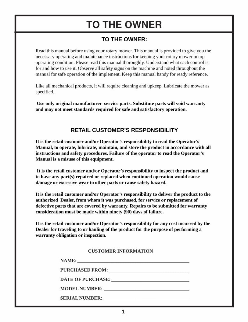
Figure 2-1 (3-Point Hitch Points)
Top Link Hitch Point
Lift ArmsHitch Pins
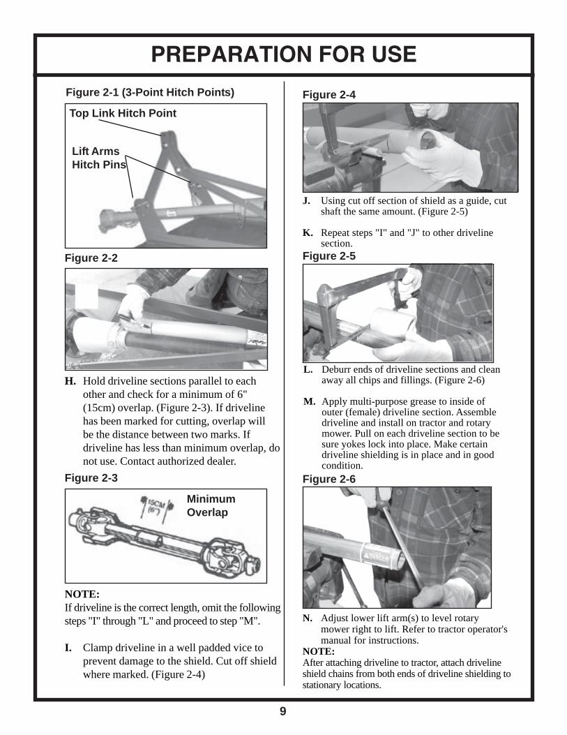
Figure 2-2
H. Hold driveline sections parallel to eachother and check for a minimum of 6"(15cm) overlap. (Figure 2-3). If drivelinehas been marked for cutting, overlap willbe the distance between two marks. Ifdriveline has less than minimum overlap, donot use. Contact authorized dealer.
Figure 2-3
NOTE:If driveline is the correct length, omit the followingsteps "I" through "L" and proceed to step "M".
I. Clamp driveline in a well padded vice toprevent damage to the shield. Cut off shieldwhere marked. (Figure 2-4)
Figure 2-4
J. Using cut off section of shield as a guide, cutshaft the same amount. (Figure 2-5)
K. Repeat steps "I" and "J" to other drivelinesection.
Figure 2-5
L. Deburr ends of driveline sections and cleanaway all chips and fillings. (Figure 2-6)
M. Apply multi-purpose grease to inside ofouter (female) driveline section. Assembledriveline and install on tractor and rotarymower. Pull on each driveline section to besure yokes lock into place. Make certaindriveline shielding is in place and in goodcondition.
Figure 2-6
N. Adjust lower lift arm(s) to level rotarymower right to lift. Refer to tractor operator'smanual for instructions.
NOTE:After attaching driveline to tractor, attach drivelineshield chains from both ends of driveline shielding tostationary locations.
MinimumOverlap
SECTION 3 - Operating Instructions
10
3-1 GENERAL SAFETY
Only qualified people should operate this machine. Operator should wear hard hat, safety glasses, andsafety shoes. It is recommended that tractor be equipped with Rollover Protective Systems (ROPS) anda seat belt be used. Before beginning operation, clear work area of objects that may be picked up andthrown. Check for ditches, stumps, holes, or other obstacles that could upset tractor or damage rotarymower. Always turn off tractor engine, set parking brake, and allow rotary mower blades to come to acomplete stop before dismounting tractor.
3-2 ADJUSTING FOR WORK
The rotary mower should be operated at the highest position which will give optimal cutting results.This will help prevent the blades from striking the ground, reducing blade wear and undue strain on themachine. For best results under heavier cutting conditions, always tilt the rotary mower approximately2 inches (51mm) lower in the front. This tilt decreases horsepower requirements and increases potentialground speed. When fine shredding is desired, adjust rotary mower deck level or slightly lower in therear. This will keep the foliage under rotary mower until thoroughly shredded. More power is requiredfor shredding.
WARNINGTHE MOWER CAN FALL FROM HYDRAULIC SYSTEM FAILURE. TO AVOID SERIOUS INJURY OR
DEATH, SECURELY SUPPORT ROTARY MOWER BEFORE WORKING UNDERNEATH.
WARNINGAVOID PLACING HANDS, FEET OR ANY OTHER BODY PARTS BENEATH THE ROTARY MOWER
WHILE MAKING HEIGHT ADJUSTMENTS.
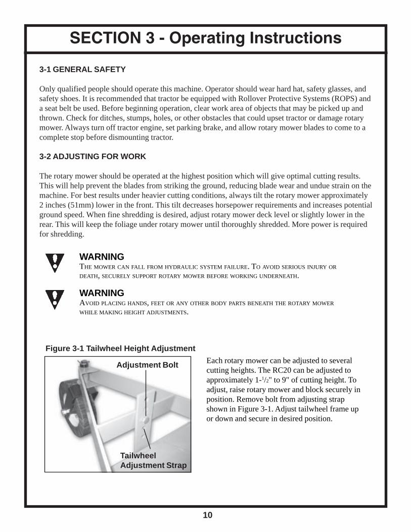
Figure 3-1 Tailwheel Height Adjustment
Each rotary mower can be adjusted to severalcutting heights. The RC20 can be adjusted toapproximately 1-1/2" to 9" of cutting height. Toadjust, raise rotary mower and block securely inposition. Remove bolt from adjusting strapshown in Figure 3-1. Adjust tailwheel frame upor down and secure in desired position.
Adjustment Bolt
TailwheelAdjustment Strap
11
OPERATING INSTRUCTIONS
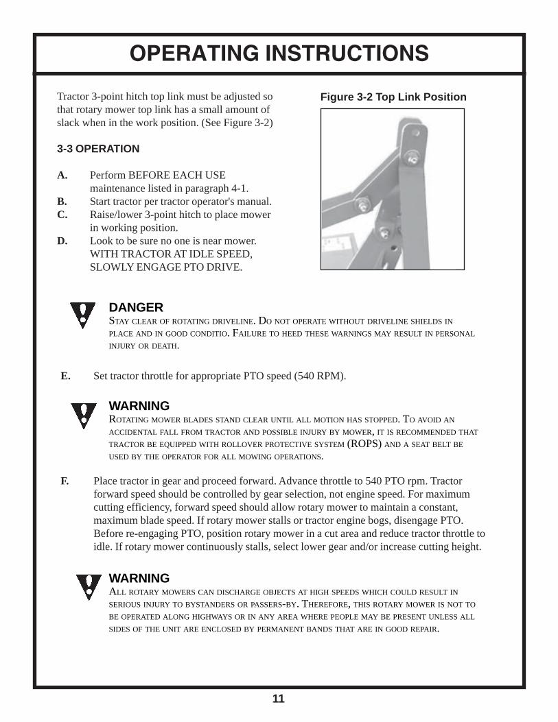
Tractor 3-point hitch top link must be adjusted sothat rotary mower top link has a small amount ofslack when in the work position. (See Figure 3-2)
3-3 OPERATION
A. Perform BEFORE EACH USEmaintenance listed in paragraph 4-1.
B. Start tractor per tractor operator's manual.C. Raise/lower 3-point hitch to place mower
in working position.D. Look to be sure no one is near mower.
WITH TRACTOR AT IDLE SPEED,SLOWLY ENGAGE PTO DRIVE.
DANGERSTAY CLEAR OF ROTATING DRIVELINE. DO NOT OPERATE WITHOUT DRIVELINE SHIELDS INPLACE AND IN GOOD CONDITIO. FAILURE TO HEED THESE WARNINGS MAY RESULT IN PERSONAL
INJURY OR DEATH.
WARNINGROTATING MOWER BLADES STAND CLEAR UNTIL ALL MOTION HAS STOPPED. TO AVOID AN
ACCIDENTAL FALL FROM TRACTOR AND POSSIBLE INJURY BY MOWER, IT IS RECOMMENDED THAT
TRACTOR BE EQUIPPED WITH ROLLOVER PROTECTIVE SYSTEM (ROPS) AND A SEAT BELT BE
USED BY THE OPERATOR FOR ALL MOWING OPERATIONS.
WARNINGALL ROTARY MOWERS CAN DISCHARGE OBJECTS AT HIGH SPEEDS WHICH COULD RESULT INSERIOUS INJURY TO BYSTANDERS OR PASSERS-BY. THEREFORE, THIS ROTARY MOWER IS NOT TO
BE OPERATED ALONG HIGHWAYS OR IN ANY AREA WHERE PEOPLE MAY BE PRESENT UNLESS ALL
SIDES OF THE UNIT ARE ENCLOSED BY PERMANENT BANDS THAT ARE IN GOOD REPAIR.
E. Set tractor throttle for appropriate PTO speed (540 RPM).
F. Place tractor in gear and proceed forward. Advance throttle to 540 PTO rpm. Tractorforward speed should be controlled by gear selection, not engine speed. For maximumcutting efficiency, forward speed should allow rotary mower to maintain a constant,maximum blade speed. If rotary mower stalls or tractor engine bogs, disengage PTO.Before re-engaging PTO, position rotary mower in a cut area and reduce tractor throttle toidle. If rotary mower continuously stalls, select lower gear and/or increase cutting height.
Figure 3-2 Top Link Position
SECTION 4 - Maintenance
12
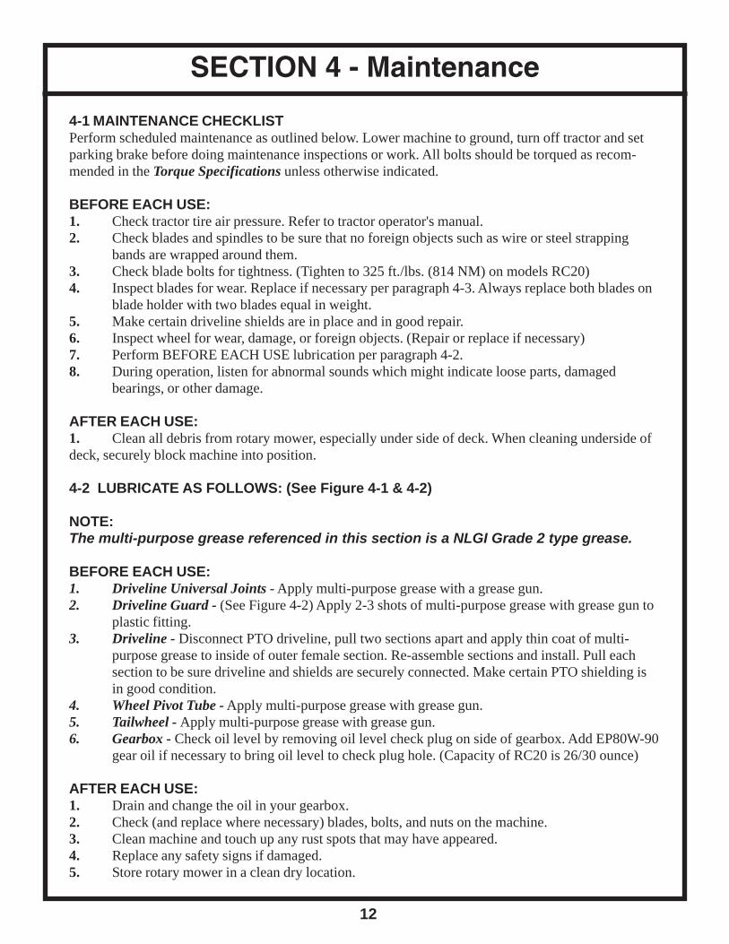
4-1 MAINTENANCE CHECKLISTPerform scheduled maintenance as outlined below. Lower machine to ground, turn off tractor and setparking brake before doing maintenance inspections or work. All bolts should be torqued as recom-mended in the Torque Specifications unless otherwise indicated.
BEFORE EACH USE:1. Check tractor tire air pressure. Refer to tractor operator's manual.2. Check blades and spindles to be sure that no foreign objects such as wire or steel strapping
bands are wrapped around them.3. Check blade bolts for tightness. (Tighten to 325 ft./lbs. (814 NM) on models RC20)4. Inspect blades for wear. Replace if necessary per paragraph 4-3. Always replace both blades on
blade holder with two blades equal in weight.5. Make certain driveline shields are in place and in good repair.6. Inspect wheel for wear, damage, or foreign objects. (Repair or replace if necessary)7. Perform BEFORE EACH USE lubrication per paragraph 4-2.8. During operation, listen for abnormal sounds which might indicate loose parts, damaged
bearings, or other damage.
AFTER EACH USE:1. Clean all debris from rotary mower, especially under side of deck. When cleaning underside ofdeck, securely block machine into position.
4-2 LUBRICATE AS FOLLOWS: (See Figure 4-1 & 4-2)
NOTE:The multi-purpose grease referenced in this section is a NLGI Grade 2 type grease.
BEFORE EACH USE:1. Driveline Universal Joints - Apply multi-purpose grease with a grease gun.2. Driveline Guard - (See Figure 4-2) Apply 2-3 shots of multi-purpose grease with grease gun to
plastic fitting.3. Driveline - Disconnect PTO driveline, pull two sections apart and apply thin coat of multi-
purpose grease to inside of outer female section. Re-assemble sections and install. Pull eachsection to be sure driveline and shields are securely connected. Make certain PTO shielding isin good condition.
4. Wheel Pivot Tube - Apply multi-purpose grease with grease gun.5. Tailwheel - Apply multi-purpose grease with grease gun.6. Gearbox - Check oil level by removing oil level check plug on side of gearbox. Add EP80W-90
gear oil if necessary to bring oil level to check plug hole. (Capacity of RC20 is 26/30 ounce)
AFTER EACH USE:1. Drain and change the oil in your gearbox.2. Check (and replace where necessary) blades, bolts, and nuts on the machine.3. Clean machine and touch up any rust spots that may have appeared.4. Replace any safety signs if damaged.5. Store rotary mower in a clean dry location.
13
MAINTENANCE
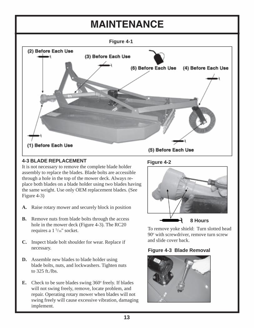
Figure 4-1
4-3 BLADE REPLACEMENTIt is not necessary to remove the complete blade holderassembly to replace the blades. Blade bolts are accessiblethrough a hole in the top of the mower deck. Always re-place both blades on a blade holder using two blades havingthe same weight. Use only OEM replacement blades. (SeeFigure 4-3)
A. Raise rotary mower and securely block in position
B. Remove nuts from blade bolts through the accesshole in the mower deck (Figure 4-3). The RC20requires a 1 5/16" socket.
C. Inspect blade bolt shoulder for wear. Replace ifnecessary.
D. Assemble new blades to blade holder usingblade bolts, nuts, and lockwashers. Tighten nutsto 325 ft./lbs.
E. Check to be sure blades swing 360o freely. If bladeswill not swing freely, remove, locate problem, andrepair. Operating rotary mower when blades will notswing freely will cause excessive vibration, damagingimplement.
Figure 4-2
8 Hours
To remove yoke shield: Turn slotted head90o with screwdriver, remove turn screwand slide cover back.
Figure 4-3 Blade Removal

MAINTENANCE
14
DANGERDO NOT GET UNDER ROTARY MOWER UNLESS IT IS SECURELY BLOCKED IN POSITION.ACCIDENTAL FALL COULD CAUSE SERIOUS INJURY OR DEATH.
4-4 SHEAR BOLT REPLACEMENT (See Figure 4-4)
A. Slide yoke shield back. (See Figure 4-2)
B. Realign holes in yoke and shaft and removesheared bolt with hammer and punch.
C. Install new shear bolt. Lock yoke shieldinto place.
Figure 4-4 Shear Bolt Replacement
(RC20 - 1/2" x 3", Grade 2 Shear Bolt)
WARNINGFAILURE TO INSTALL RETAINING CLIP ON INPUT SHAFT WILL ALLOW DRIVELINE TO SWING
FREELY IF BOLT IS SHEARED CAUSING POSSIBLE INJURY OR DEATH.
4-5 SLIP CLUTCH OPERATIONAL CHECK
After the implement has been stored for 30 days or more, perform the following operational check:A. Loosen eight nuts retaining clutch springs 1/3 turn or until spring can be turned with fingers.
B. With tractor at idle speed, engage tractor PTO drive 2-3 seconds. Clutch should slip withoutturning blades. If clutch does not slip, contact your authorized dealer.
C. Retighten nuts to original position. Initial spring lengths are shown in Figure 4-5.
IMPORTANT:FAILURE TO RETIGHTEN NUTS TO ORIGINAL POSITION MAY CAUSE DAMAGE TOIMPLEMENT AND/OR TRACTOR DUE TO IMPROPER SLIP CLUTCH TORQUE SETTING
4-6 SLIP CLUTCH ADJUSTMENTThe slip clutch is factory preset to the correct torque for protectingimplement and tractor. Periodic adjustment is recommended; referto section 4-5. Should adjustments be needed, first check to be sureall spring lengths are the same. Initial spring lengths are shown inFigure 4-5. If necessary, adjust nut on any spring that is unequal.Adjust all eight spring retaining nuts 1/3 of a turn (2 flats on a nut)and check clutch slippage. If further adjustment is necessary, do soin 1/3 turn increments. Adjust only to provide sufficient torque toprevent slippage under normal conditions. Occasional slippage isnormal for driveline protection. If satisfactory results cannot beobtained, consult your authorized dealer.
Figure 4-5 Spring Lengths
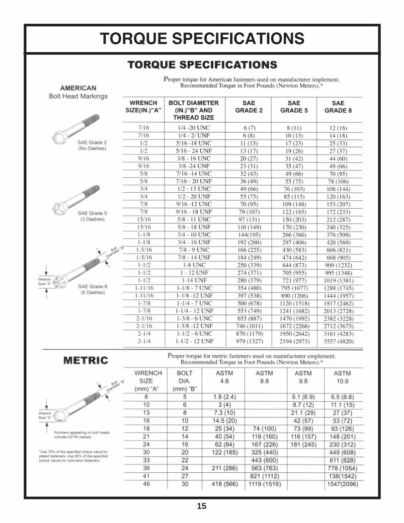
15
TORQUE SPECIFICATIONS

SECTION 5 - Parts
16
REF# QTY. PART NO. DESCRIPTION
1 1 N/A Deck Assembly2 2 100107 Brand Label3 1 300101 Warning / Danger Decal4 2 300102 Top Link Mount5 1 300103 Hitch Pivot Link6 2 300104 Lift Strap - 48"6 2 300138 Lift Strap - 60"6 2 300139 Lift Strap - 72"7 1 300105 Gearbox - 40 HP8 1 300107 Tailwheel Adjustment Strap9 1 300108 A-Frame (Tailwheel)10 1 300109 Tailwheel Fork11 1 300110 Tailwheel Assembly12 1 300111 Dust Cover (Black Plug)

17
ARTICULATED HITCH ASSEMBLY
REF# QTY. PART NO. DESCRIPTION
1 1 N/A Hitch Mount Lug2 2 300102 Top Link Mount3 1 300112 Lift Link Bushing4 1 300103 Hitch Pivot Link5 2 300104 Lift Strap 48"5 2 300138 Lift Strap 60"5 2 300139 Lift Strap 72"6 1 100110 Hitch Bolt 3/4" x 2 1/2", Grade 57 2 100111 Flat Washer 3/4"8 1 100112 Lock Nut 3/4"9 2 100101 Lift Pin (with lockwasher & nut)10 1 100102 Link Pivot Bolt 3/4" x 5", Grade 511 2 100111 Flat Washer 3/4"12 1 100112 Lock Nut 3/4"13 1 100110 HItch Bolt 3/4" x 2 1/2", Grade 514 1 100111 Flat Washer 3/4"15 1 100112 Lock Nut 3/4"

GEARBOX & BLADE PAN ASSEMBLY
18
REF# QTY. PART NO. DESCRIPTION
1 1 300113 Blade Pan 48" & 60"1 1 300114 Blade Pan 72"2 1 300125 Blade Set (2 blades) 48"2 1 300126 Blade Set (2 blades) 60" & 72"3 2 300117 Blade Washer4 2 300118 Blade Bolt Assembly5 1 300119 Standard PTO Shaft w/Shear Pin 48" & 60"5 1 300120 Standard PTO Shaft w/Shear Pin 72"5 1 300121 Standard PTO Shaft w/Slip Clutch 48" & 60"5 1 300122 Standard PTO Shaft W/Slip Clutch 72"6 1 300105 40 HP Gearbox7 1 300123 Blade Hub Nut8 1 100113 Cotter Pin - Gearbox9 1 300124 Slip Clutch Shield
IMPORTANTWhen sharpening blades, grind each blade the sameamount to maintain balance. Replace blades in pairs.Unbalanced blades will cause excessive vibrationwhich can damage gearbox bearings. Vibration mayalso cause structural cracks to mower deck.
Sharpen both blades at the same time to maintainbalance. Follow original sharpening pattern. Do notsharper blade to a razor edge, but leave at least a 1/16"blunt edge. Do not sharpen back side of blade.
GEARBOX ASSEMBLY
19
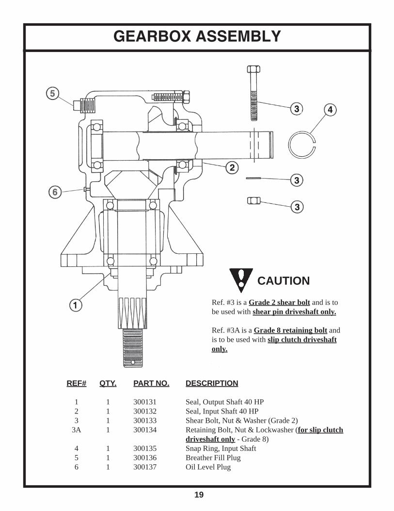
REF# QTY. PART NO. DESCRIPTION
1 1 300131 Seal, Output Shaft 40 HP2 1 300132 Seal, Input Shaft 40 HP3 1 300133 Shear Bolt, Nut & Washer (Grade 2)
3A 1 300134 Retaining Bolt, Nut & Lockwasher (for slip clutchdriveshaft only - Grade 8)
4 1 300135 Snap Ring, Input Shaft5 1 300136 Breather Fill Plug6 1 300137 Oil Level Plug
CAUTION
Ref. #3 is a Grade 2 shear bolt and is tobe used with shear pin driveshaft only.
Ref. #3A is a Grade 8 retaining bolt andis to be used with slip clutch driveshaftonly.

20
TAILWHEEL ASSEMBLY
REF# QTY. PART NO. DESCRIPTION
1 1 300127 Tailwheel2 1 300109 Tailwheel Fork3 1 300108 A-Frame Assembly (Tailwheel)4 1 300128 Axle Bolt 1" x 8" w/Flat Washer, Nut, Cotter Pin5 1 300107 Tailwheel Adjustment Strap6 1 100114 Cotter Pin7 1 300129 Bushing (Tailwheel)8 1 100115 1 1/4 Washer9 1 100116 Grease Zerk10 1 300130 Hub w/Lock Washer, Nut (Tailwheel)11 1 100110 Bolt 3/4" x 2 1/2"12 3 100111 Flat Washer 3/4"13 1 100112 Lock Nut 3/4"14 1 100117 Bolt 5/8" x 2", Grade 515 1 100118 Lock Washer 5/8"16 1 100119 Hex Nut 5/8"

RUBBER BELT GUARD ASSEMBLY
21
PART NUMBERSREF# QTY. RC20-48 RC20-60 RC20-72 DESCRIPTION
1 1 300158 300159 300160 Front Belt Guard Frame2 1 300161 300161 300161 Rear Belt Guard Frame3 1 300155 300156 300157 Front Belt4 1 300162 300162 300162 Rear Belt5 1 300175 300176 300177 Front Belt Guard Kit6 1 300178 300178 300178 Rear Belt Guard Kit7 7 100141 100141 100141 Bolt 5/16" x 3", Grade 58 7 100142 100142 100142 Flat Washer 5/16"9 7 100134 100134 100134 Lock Washer 5/16"
10 7 100135 100135 100135 Hex Nut 5/16"
22
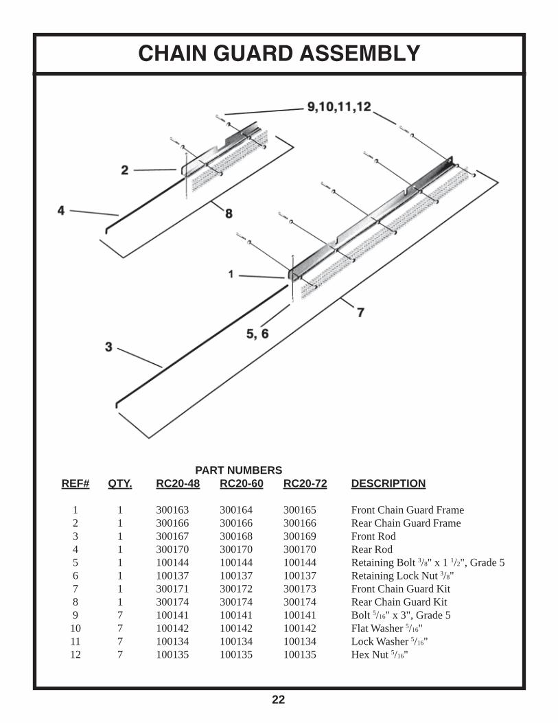
CHAIN GUARD ASSEMBLY
PART NUMBERSREF# QTY. RC20-48 RC20-60 RC20-72 DESCRIPTION
1 1 300163 300164 300165 Front Chain Guard Frame2 1 300166 300166 300166 Rear Chain Guard Frame3 1 300167 300168 300169 Front Rod4 1 300170 300170 300170 Rear Rod5 1 100144 100144 100144 Retaining Bolt 3/8" x 1 1/2", Grade 56 1 100137 100137 100137 Retaining Lock Nut 3/8"7 1 300171 300172 300173 Front Chain Guard Kit8 1 300174 300174 300174 Rear Chain Guard Kit9 7 100141 100141 100141 Bolt 5/16" x 3", Grade 5
10 7 100142 100142 100142 Flat Washer 5/16"11 7 100134 100134 100134 Lock Washer 5/16"12 7 100135 100135 100135 Hex Nut 5/16"

SECTION 6 - Rubber Belt Guard Installation
23
Shields, Guards, and Deflectors are provided for the protection of the operator andbystanders. The Manufacturer strongly recommends the use of Protective Shielding atall times. DO NOT operate the machine without Shields in place.
1. Insert 5/16" x 3" bolts and flat washers (items 3 & 4) through hole from inside out of rotary mower.
2. Place belt guard (item 2) against tube frame of rotary mower and install front belt guard frame (item 1)flat washers, lock washers, and nuts until all are installed, clamping belt guard between belt guardframe and rotary mower front tube.
3. Repeat process for rear belt guard.
WARNINGROTARY MOWER MUST BE EQUIPPED WITH FRONT AND REAR GUARDS WHEN OPERATING IN THE
VICINITY OF HIGHWAYS OR IN ANY AREA WHERE PEOPLE MAY BE PRESENT.
24
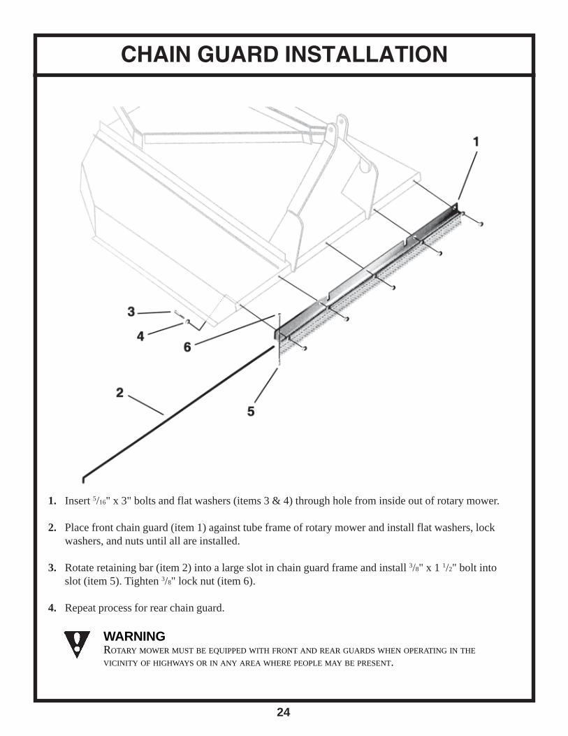
CHAIN GUARD INSTALLATION
1. Insert 5/16" x 3" bolts and flat washers (items 3 & 4) through hole from inside out of rotary mower.
2. Place front chain guard (item 1) against tube frame of rotary mower and install flat washers, lockwashers, and nuts until all are installed.
3. Rotate retaining bar (item 2) into a large slot in chain guard frame and install 3/8" x 1 1/2" bolt intoslot (item 5). Tighten 3/8" lock nut (item 6).
4. Repeat process for rear chain guard.
WARNINGROTARY MOWER MUST BE EQUIPPED WITH FRONT AND REAR GUARDS WHEN OPERATING IN THE
VICINITY OF HIGHWAYS OR IN ANY AREA WHERE PEOPLE MAY BE PRESENT.
25
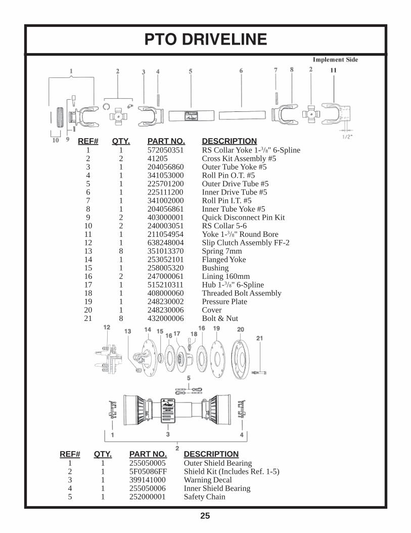
PTO DRIVELINE
REF# QTY. PART NO. DESCRIPTION1 1 572050351 RS Collar Yoke 1-3/8" 6-Spline2 2 41205 Cross Kit Assembly #53 1 204056860 Outer Tube Yoke #54 1 341053000 Roll Pin O.T. #55 1 225701200 Outer Drive Tube #56 1 225111200 Inner Drive Tube #57 1 341002000 Roll Pin I.T. #58 1 204056861 Inner Tube Yoke #59 2 403000001 Quick Disconnect Pin Kit10 2 240003051 RS Collar 5-611 1 211054954 Yoke 1-3/8" Round Bore12 1 638248004 Slip Clutch Assembly FF-213 8 351013370 Spring 7mm14 1 253052101 Flanged Yoke15 1 258005320 Bushing16 2 247000061 Lining 160mm17 1 515210311 Hub 1-3/8" 6-Spline18 1 408000060 Threaded Bolt Assembly19 1 248230002 Pressure Plate20 1 248230006 Cover21 8 432000006 Bolt & Nut
REF# QTY. PART NO. DESCRIPTION1 1 255050005 Outer Shield Bearing2 1 5F05086FF Shield Kit (Includes Ref. 1-5)3 1 399141000 Warning Decal4 1 255050006 Inner Shield Bearing5 1 252000001 Safety Chain

TROUBLESHOOTING GUIDE
26
Problem: Possible Cause: Possible Remedy:
Leaves a streak of uncut orpartially cut grass
Mower not level, side to side
Blade dull or bent.
Blades unable to cut that part of grasspressed by path of tractor tires.
Possible build up of material undermower.
Level 3-pt. hitch linkage on tractor.
Sharpen or replace blades.
Slow ground speed of tractor but keep enginerunning at full PTO rpm. Cutting lower will help.
Clean rotary mower.
Blade cuts grass lower incenter of swath than at theedge.
Height of rotary mower lower at rear or atfront.
Adjust rotary mower height and altitude so thatrotary mower rear and front are within 1/2" ofsame height.
Material discharges frommower unevenly, ordischarges clumps of grass.
Grass or brush may be too high or thick.
Grass wet.
Reduce ground speed but maintain 540 rpm attractor PTO, or make two passes over material.Raise rotary mower for the first pass and lower forthe second pass, preferably cutting 90o to the thefirst pass. Raise rear of rotary mower high enoughto permit material to discharge.
Allow grass to dry before mowing. Slow groundspeed of tractor but keep engine running at fullPTO rpm. Cutting lower will help.
Gearbox overheating. Low on lubricant
Improper lubricant type.
Excessive trash build up around gearbox
Fill to proper level.
Replace with proper lubricant.
Remove trash.
Rotary mower will not cut.
Rotary mower will not cut allthe time. (slip clutch only)
Shear bolt sheared
Slip clutch slipping.
Install new shear bolt.
Adjust slip clutch according to guidelines on page14 (Fig. 4-5)
Excessive vibration. Possible build up of material on blade.
Blades locked into position.
Check for even wear on each blade tip.
Broken blade.
New blade or bolts not matched withworn blade or bolts.
Clean blade pan.
Free blades so they swing free.
Weigh each blade. Weight should be within 1 oz.Always replace both blades.
Replace blades, in set.
Replace blades or bolts in sets.
Gearbox noisy. Low oil in gearbox. Check oil level. Add oil.
LIMITED WARRANTY
GEARMORE, INC., warrants each new Gearmore product to be free from defects in material andworkmanship for a period of twelve (12) months from date of purchase to the original purchaser.This warranty shall not apply to implements or parts that have been subject to misuse, negli-gence, accident, or that have been altered in any way.
Our obligation shall be limited to repairing or replacement of any part, provided that such part isreturned within thirty (30) days from date of failure to Gearmore through the dealer from whomthe purchase was made, transportation charges prepaid.
This warranty shall not be interpreted to render us liable for injury or damages of any kind ornature, direct, consequential or contingent, to person or property. This warranty does not extendto loss of crops, loss because of delay in harvesting or any other expenses, for any other rea-sons.
Gearmore in no way warranties engines, tires, or other trade accessories, since these items arewarranted separately by these respective manufacturers.
Gearmore reserves the right to make improvements in design or changes in specification at anytime, without incurring any obligations to owners or units previously sold.
GEARMORE, INC.13477 Benson Ave.
Chino, CA 91710Always refer to and heed machine operating warning decals on machine.
27
The serial number of this product is stored in our computer database, thussubmitting a warranty registration card is not required.