Embed Size (px)
Citation preview

Contents116 Overview
117 1.88 – 2.62” (47,8 – 66,5 mm) Diameter Tables
118 2.38” (60,5 mm) Diameter Tables
119 2.75 – 4.75” Diameter Tables
120-121 5.0 – 12.0” Diameter Tables
122 Performance Curves
115
Parker Daedal rotary stages are designed to produce precision rotary
motion. The basic components in these stages are a base, main
bearing, drive mechanism and top (load platform). The base houses
the main bearing and drive mechanism and is design to be mounted
to a stationary surface. The main bearings provide low friction contact
between the base and top. The drive mechanisms used are either
tangent arms or worm gears. The table top provides a mounting surface
for mounting payloads.
Rotary Positionerstangent arm and worm gear drive

Rotary Positioners
Parker Hannifin CorporationElectromechanical Automation Division
Irwin, Pennsylvania116
www.parkermotion.com
Rotary Positioning Stages
• Precision quality • Budget friendly• Largest selection• Rotary-linear configurations• No maintenance• Vacuum preparation and custom
options
Features and Overview
Rotary Positioner PrinciplesParker Daedal rotary stages and tables produce controlled rotation and angular positioning.
Tangent Arm Drive
With some stages (models 2520, 2525, 4575), the drive mechanism is a tangent arm drive. Angular rotation, with this system, is controlled by three control knobs. The release knob disengages the shaft from the drive, freeing the table to be rotated by hand to a desired location. The release knob is then tightened to re-engage the drive mechanism and transfer control to the adjustment knob which, when rotated, produces precise angular positioning of the shaft and table top. The locking knob can then be used to positively lock the table at the desired setting.
Precision Worm Gear Drive
A precision worm gear drive is employed as the drive mechanism for the other Parker Daedal stages. A worm wheel (gear), which is attached to the table shaft, meshes with the worm drive, whose shaft extends out of the housing. Controlled rotation of the worm shaft creates precise angular rotation of the worm wheel and table shaft. The worm gear and shaft are matched sets and are preloaded to remove backlash. This type of drive provides high resolution (180:1) and continuous angular positioning over a full 360° range.
Standard FeaturesParker Daedal has engineered all of its rotary positioners with emphasis on construction and detail. The resulting stages exhibit outstanding quality and proven, reliable performance. All models are manufactured on the very best automated equipment, skillfully assembled, and thoroughly inspected and tested. This enables units manufactured in production quantities to satisfy critical performance specifications. All Parker Daedal rotary positioning devices feature:
• Aluminum/steel construction• Protective black anodize finish• Low-friction rotary adjustment• Precise/accurate movement• Trouble-free operation
How to OrderUse the Selection Chart below to determine the appropriate model series. Refer to individual series pages for complete performance and mechanical specifications. To order, use the model number specific to the selected table.
Model Series Table Diameter Drive Mechanism Normal Load
Mounting
PageImperial Metric
2500M2500
1.88 –2.62 in47,7 – 66,5 mm Tangent Arm 10 lb
4,5 kg•
• 117
4575*M4575*
2.38 in60,5 mm Tangent Arm 5 lbs
2,25 kg•
• 118
10000-20000M10000-M20000
2.75 – 4.75 in69,8 – 120,6 mm Worm Gear 50 lbs
22,0 kg•
• 119
30000M30000
5.00 – 12.00 in 127,0 – 305,0 mm Worm Gear 25 – 200 lbs
11,5 – 90,0 kg•
• 120-121
* Models 4575/M4575 are combination rotary and linear stages which also provide 0.50 in (12,7 mm) of linear travel.

Parker Hannifin CorporationElectromechanical Automation DivisionIrwin, Pennsylvania 117
Ro
tary
P
ositi
oner
s
2500/M2500 Series Specifications
Qty. (4) C'bored Mtg. Holes (Base)English models – #6 S.H.C.S.Metric models – M3 S.H.C.S.
1.75(44,4)
1.75(44,4)
1.00(25,4)
1.00(25,4)
0.88(25,3)
0.28(7,1)
0.38(9,7)
DC’trd
DC’trd
DC’trd
0.375 (9,53) dia. 32 UNF-2B tapped thru
0.50 (12,7) dia. thru2520/M2520: 1.88 (47,7) dia.2525/M2525: 2.00 (50,8) dia.
Qty. (2) Mtg. Holes (Base)English models – 1/4 S.H.C.S.Metric models – M6 S.H.C.S.
Qty. (4) Mtg. Holes (Top) on "E" dia. B.C.English models – 1/4-20 thd.Metric models – M6 thd.
Qty. (4) Mtg. Holes (Top) on "B" dia. B.C.English models – #6 thd.Metric models – M3 thd.
Qty. (4) Mtg. Holes (Ttop) equally spaced on "A", "B", & "C" dia. B.C.12 holes total:English models – #6-32 thd.Metric models – M3 thd.
1.31(33,3)
2.62(66,5)
2.62(66,5)
2520/M25202525/M2525
2530/M25302535/M2535
Series 2500 rotary positioners offer low-friction rotary positioning, quick manual table top rotation, precise angular adjustment at any selected position, and positive locking. These miniature units have a preloaded angular contact ball bearing system which provides smooth, continuous rotary movement.
Models 2525/M2525 and 2535/M2535 include a dial and vernier for direct position readout (readable to six arc-minutes). These stages can be mounted in a horizontal or vertical position, and can be combined with compatible linear stages for linear-rotary applications.
2500/M2500 SeriesSpecifications Imperial Models Metric Models
Load: Normal Moment
10 lbs See page 122
4,5 kg See page 122
Range: 360° (free rotation)10° (fine positioning)
360° (free rotation)10° (fine positioning)
Weight: 1.0 – 1.8 lbs 0,5 – 0,8 kg
Vernier Resolution: 12 arc-min 12 arc-min
Construction: Aluminum top and base; steel tangent arm drive
Aluminum top and base; steel tangent arm drive
Mounting surface: Precision machined Precision machined
Finish: Black anodize Black anodize
ModelDiameterin (mm)
Vernier Readout
Aperture Diameterin (mm)
Weight lbs (kg)
Dimensions – in (mm)A B C D E
Imperial
2520 1.88 No 0.25 1.0 0.625 1.125 1.50 1.00 –2525 2.00 Yes 0.25 1.0 0.625 1.125 1.50 1.00 –2530 2.62 No 0.50 1.8 – 1.125 – 2.00 2.002535 2.62 Yes 0.50 1.8 – 1.125 – 2.00 2.00
Metric
M2520 (47,7) No (6,3) (0,5) (15,0) (25,0) (35,0) (25,0) –M2525 (50,8) Yes (6,3) (0,5) (15,0) (25,0) (35,0) (25,0) –M2530 (66,5) No (12,7) (0,8) – (25,0) – (50,0) (50,0)M2535 (66,5) Yes (12,7) (0,8) – (25,0) – (50,0) (50,0)
Dimensions Inches (mm)

Rotary Positioners
Parker Hannifin CorporationElectromechanical Automation Division
Irwin, Pennsylvania118
www.parkermotion.com
Combination Linear/Rotary PositionerThe model 4575 combines both linear and rotary motion into one compact unit. It is designed for applications where space restrictions do not allow stacking a linear stage and a rotary stage. The mounting surface is 2.38” diameter with a 0.75” diameter thru hole, with (4) #10-32 threaded mounting holes on 2.00” centers. Linear travel is provided by a fine resolution micrometer. Rotary travel is provided with both a coarse and a fine adjustment. This feature allows quick rotation over a continuous 360° range, plus precise angular adjustment at any selected position.
4575/M4575 SeriesSpecifications Imperial Models Metric Models
Load: Normal Moment
15 lbs See page 122
2,25 kg See page 122
Range: Rotary
Linear
360° (free rotation)10° (fine positioning)0.50 in
360° (free rotation)10° (fine positioning)12,7 mm
Straight line accuracy: 0.0001 in 2,5 μm
Micrometer graduations: 0.001 in 0,01 mm
Weight: 1.0 lb 0,5 kg
Construction: Aluminum top and base; steel tangent arm drive
Aluminum top and base; steel tangent arm drive
Mounting surface: Precision machined Precision machined
Finish: Black anodize Black anodize
ModelDiameterin (mm)
Aperture Diameterin (mm)
Dimensions – in (mm)A B C
Imperial 4575 2.62 0.75 2.00 0.31 2.00Metric M4575 (66,5) (19,0) (50,0) (8,3) (50,0)
Dimensions Inches (mm)
4575/M4575 Series Specifications
0.38 (9,7)
2.62(66,5)
0.62 (15,7)
Qty. (4) Mtg. Holes (Top) on “C” dia. B.C.Imperial – #10-32 thd.Metric – M5 thd.
Qty. (2) C’bored Mtg. Holes (Base)Imperial – 1/4” S.H.C.S.Metric – M6 S.H.C.S.
0.75 (19,0) dia.
2.67 (67,8)(mid-travel)
2.62(66,5)
2.44 (62,0) dia.
1.25(31,7)
1.31(33,3)
AB

Parker Hannifin CorporationElectromechanical Automation DivisionIrwin, Pennsylvania 119
Ro
tary
P
ositi
oner
s
10000-20000/M10000-M20000 Series Specifications
The 10000-20000 and M10000-M20000 Series rotary positioning stages provide smooth, continuous adjustment over a full 360° travel range. The drive mechanism features a worm gear drive. A position locking knob allows the stage to be positively locked in place. The 10000 and 20000 models offer a 2.75 inch (69,8 mm) diameter stage with a calibrated dial and vernier, readable to 6.00 arc minutes. The 10001 and 20001 models, which do not include the vernier readout, offer a larger 4.75 inch (120,6 mm) diameter mounting surface. These versatile low cost units can be combined with linear positioning stages having 4.00 inch (Imperial) or 100,0 mm (Metric) mounting hole centers for multi-axis polar set-ups.
10000-20000/M10000-M20000 Series
Specifications
Imperial Models Metric Models
10000 10001 20000 20001 M10000 M10001 M20000 M20001
Table Diameter: 2.75 in 4.75 in 2.75 in 4.75 in 69,8 mm 120,7 mm 69,8 mm 120,7 mm
Vernier Resolution: 6 arc-min – 6 arc-min – 6 arc-min – 6 arc-min –
Aperture: 0.25 0.25 1.50 1.50 (6,3) (6,3) (38,1) (38,1)
Weight: 2.0 lbs 2.4 lbs 2.0 lbs 2.4 lbs 0,9 kg 1,9 kg 0,9 kg 1,9 kg
Load: Normal Moment
25 lbs
Not recommended for moment loads11,3 kg
Not recommended for moment loads
Range: 360° (continuous) 360° (continuous)
Drive Ratio: 120:1 120:1
Construction: Aluminum top and base; steel/bronze worm gear drive Aluminum top and base; steel/bronze worm gear drive
Mounting surface: Precision machined Precision machined
Finish: Black anodize Black anodize
Dimensions Inches (mm)
Models10000-20000
M10000-M20000
Models10001-20001
M10001-M20001
4.75(120,7)
4.75(120,7)
4.75(120,7)
4.75(120,7)
2.75(69.8)
1.16(29,5)
1.16(29,5)
Qty. (4) C'bored Mtg. Holes (Base)Imperial Models – 1/4 S.H.C.S.Metric Models – M6 S.H.C.S.
Qty. (4) Mtg. Holes (Top)Imperial Models – #10-32 thd. on a 2.00” dia. B.C.Metric Models – M4 thd. on a 50,0 mm dia. B.C.
Qty. (4) Mtg. Holes (Top)Imperial Models – #10-32 thd. on a 2.00” dia. B.C.Metric Models – M4 thd. on a 50,0 mm dia. B.C.
Qty. (4) C'bored Mtg. Holes (Base)Imperial Models – 1/4 S.H.C.S.Metric Models – M6 S.H.C.S.
1.00(25,4)
Qty. (8) Mtg. Holes (Top)Imperial Models – #10-32 thd. on a 4.00” dia. B.C.Metric Models – M4 thd. on a 100,0 mm dia. B.C.
10000/M10000: 0.25 (6,4) dia. Aperture20000/M20000: 1.50 (38,1) dia. Aperture
10001/M10001: 0.25 (6,4) dia. Aperture20001/M20001: 1.50 (38,1) dia. Aperture
1.25(31,8)
Imperial Models – 4.00 C’trdMetric Models – 100,0 C’trd
Imperial Models – 4.00 C’trdMetric Models – 100,0 C’trd

Rotary Positioners
Parker Hannifin CorporationElectromechanical Automation Division
Irwin, Pennsylvania120
www.parkermotion.com
Parker Daedal rotary indexing tables provide accurate rotational positioning with a heavy load-carrying capability. Tables feature a crossed roller bearing system which is stiffly pre-loaded to produce precise rotation of the table top. The drive mechanism is a precision worm gear drive which provides precise rotational positioning.
An angular readout—graduated in degrees—is provided around the circumference of the table top, while a finer position readout dial, found on the control knob, reads directly in 0.01° increments, with the vernier providing even higher (0.002°) resolution. A thumbscrew lock is included to lock the table at the desired setting.
For customer convenience, threaded mounting holes with locking threaded inserts are provided as well as a clearance hole through the center of the table to allow easy access from below.
If desired, the table top can easily be removed to permit custom modification. These units can be mounted in any orientation and are compatible with Parker Daedal linear tables.
30000/M30000 SeriesSpecifications Imperial Models Metric Models
Load: Normal Moment
25 – 200 lbs
See page 12211,5 – 90 kg
See page 122
Concentricity: Standard Precision
0.005 in0.001 in
127,0 μm25,4 μm
Runout: Standard Precision
0.003 in0.001 in
75 μm25 μm
Range: 360° (continuous) 360° (continuous)
Weight: 6.0 – 31.0 lbs 2,7– 14,1 kg
Vernier Resolution: 0.12 arc-min 0.12 arc-min
Construction: Aluminum top and base; steel/bronze worm gear drive
Aluminum top and base; steel/bronze worm gear drive
Mounting surface: Precision machined Precision machined
Finish: Black anodize Black anodize
Model Table Diameterin (mm)
Normal Load lbs (kg)
Output Torque in-lb (Nm)
Weight lbs (kg)Standard Precision
Imperial
30005-S 30005-P 5.00 25 25 6.030006-S 30006-P 6.00 150 40 8.030008-S 30008-P 8.00 75 40 15.030010-S 30010-P 10.00 200 190 27.030012-S 30012-P 12.00 200 190 31.0
Metric
M30005-S M30005-P (127,0) (11,5) (2,8) (2,7)M30006-S M30006-P (152,4) (68,0) (4,5) (3,6)M30008-S M30008-P (203,2) (34,0) (4,5) (6,8)M30010-S M30010-P (254,0) (90,0) (21,5) (12,2)M30012-S M30012-P (304,8) (90,0) (21,5) (14,1)
30000/M30000 Series Specifications

Parker Hannifin CorporationElectromechanical Automation DivisionIrwin, Pennsylvania 121
Ro
tary
P
ositi
oner
s
30000/M30000 Series Specifications
ModelDimensions – in (mm)
A B C D E F G H J K
Imperial
30005-S/P 5.00 1.00 5.00 4.00 1.82 0.38 1.13 1.67 3.00 4.0030006-S/P 6.00 1.75 6.00 5.00 2.00 0.38 1.23 2.04 4.00 5.0030008-S/P 8.00 1.75 8.00 6.00 2.50 0.50 1.57 2.04 4.00 6.0030010-S/P 10.00 2.00 10.00 9.00 3.00 0.75 1.81 3.03 6.00 8.0030012-S/P 12.00 2.00 10.00 9.00 3.00 0.75 1.81 3.03 8.00 10.00
Metric
M30005-S/P (127,0) (25,4) (127,0) (100,0) (46,2) (9,7) (28,7) (42,4) (75,0) (100,0)M30006-S/P (152,4) (44,5) (152,4) (125,0) (50,8) (9,7) (31,2) (51,8) (100,0) (125,0)M30008-S/P (203,2) (44,5) (203,2) (175,0) (63,5) (12,7) (39,9) (51,8) (100,0) (175,0)M30010-S/P (254,0) (50,8) (254,0) (225,0) (76,2) (19,1) (46,0) (77,0) (150,0) (200,0)M30012-S/P (304,8) (50,8) (254,0) (225,0) (76,2) (19,1) (46,0) (77,0) (200,0) (250,0)
Dimensions Inches (mm)
DC’trd
DC’trd
C
C
F
EG
2.25 (57,2)square
H
2.00(50,8)dia.
B dia. Aperture
A dia.1.50
(38,1)
1.13(28,7)
2.00(50,8)
Qty. (4) Mtg. Holes (Top) on "K" dia. B.C.Imperial models – 1/4-20 thd.Metric models – M6 thd.
Qty. (4) Mtg. Holes (Top) on "J" dia. B.C.Imperial models – 1/4-20 thd.Metric models – M6 thd.
Qty. (4) C'bored Mtg. Holes (Base)Imperial Models – 1/4 S.H.C.S.Metric Models – M6 S.H.C.S.

Rotary Positioners
Parker Hannifin CorporationElectromechanical Automation Division
Irwin, Pennsylvania122
www.parkermotion.com
Moment Load
Rotary Positioner Specifications
2520/M25202525/M2525incm
A(moment arm)
Load(force)
(lbs)(N)
218,94,5 13,4 17,8 22,3 26,7 31,2 35,6 40,0 44,5
0
8,89
0
3.50
7,62 3.00
6,35 2.50
5,08 2.00
3,81 1.50
2,54 1.00
1,27 0.50
2530/M25302535/M2535incm
A(moment arm)
Load(force)
(lbs)(N)
0
17,78
0
7.00
15,24 6.00
12,70 5.00
10,16 4.00
7,62 3.00
5,08 2.00
2,54 1.00
218,94,5 13,4 17,8 22,3 26,7 31,2 35,6 40,0 44,5
4575/M4575incm
A(moment arm)
Load(force)
(lbs)(N)
0
17,78
0
7.00
15,24 6.00
12,70 5.00
10,16 4.00
7,62 3.00
5,08 2.00
2,54 1.00
1.00.5 1.5 2.0 2.5 3.0 3.5 4.0 4.5 5.04,52,2 6,7 8,9 11,1 13,4 15,6 17,8 20,0 22,3
30005/M30005incm
A(moment arm)
2 259 111
418
627
836
1045
1253
1462
1671
1880
2089
2298
24107
Load(force)
(lbs)
(lbs)
(N)
2.00
0
4.00
6.00
8.00
10.00
12.00
5,08
0
10,16
15,24
20,32
25,40
30,48
30006/M30006in
5.00
0
25.00
cm
12,70
0
63,50
A(moment arm)
10.0025,40
15.0038,10
20.0050,80
Load(force)(N)
10 15045 668
2089
30134
40178
50223
60267
70312
80356
90401
100445
110490
120534
130579
140623
30008/M30008incm
A(moment arm)
30010 & 30012M30010 & M30012in
20 200
cm
A(moment arm)
89 89040
17860
26780
356100445
120534
140623
160712
180801
Load(force)
(lbs)(N)
2.00
0
16.00
0
4.00
6.00
8.00
10.00
12.00
14.00
40.64
35.56
30.48
25.40
20.32
15.24
10.16
5.08
0
3.50
incm
0 0
7.00
10,16 4.00
7,62 3.00
5,08 2.00
2,54 1.00
2 3 4 5 6 7 8 9
3 4 5 6 7 8 9
10
10
1
2,54 1.00
(lbs)
5.00
0
25.00
12,70
0
63,50
10.0025,40
15.0038,10
20.0050,80
Load(force)(N)
10 15045 668
2089
30134
40178
50223
60267
70312
80356
90401
100445
110490
120534
130579
140623

Contents124-127 Z-Axis Brackets
128-129 Micrometer Heads
130-132 Optical Mounts
123
Parker Daedal offers a complete line of Z-axis brackets to combine ball
bearing and cross roller stages into three axis positioning systems. We
also offer drive mechanisms in an assortment of standard and digital
micrometer heads, fine adjustment screws, and differential screws.
Optical components including beam directors, optical mounts, mirror
mounts and optical cells are also available.
Accessoriesfor linear and rotary positioners

Accessories
Parker Hannifin CorporationElectromechanical Automation Division
Irwin, Pennsylvania124
www.parkermotion.com
Z-Axis Brackets
Z-Axis Brackets
Dimensions – in (mm) Thd. NModel A B C D E F G H JJ K L M
Imp
eria
l 3909 1.25 1.25 0.25 1.38 0.25 0.156 0.62 0.19 0.38 0.88 0.44 0.88 #4-403959 1.25 1.25 0.25 1.38 0.25 0.156 0.62 0.19 0.04 0.88 0.44 0.88 #4-404009 1.75 1.69 0.25 1.88 — 0.156 0.88 0.31 0.63 1.12 — 1.12 #6-324509 2.44 2.62 0.38 2.75 — 0.218 1.22 0.31 0.93 2.00 — 2.00 #10-32
Met
ric
M3909 (31,8) (31,8) (6,4) (35,1) (6,4) (4,0) (15,7) (5,9) (9,7) (20,0) (10,0) (20,0) M3M3959 (31,8) (31,8) (6,4) (35,1) (6,4) (4,0) (15,7) (5,9) (1,0) (20,0) (10,0) (20,0) M3M4009 (44,5) (42,9) (6,4) (47,8) — (4,8) (22,4) (7,3) (16,0) (30,0) — (30,0) M4M4509 (62,0) (66,5) (9,7) (69,9) — (7,3) (31,0) (8,4) (23,6) (50,0) — (50,0) M6
K
H
AD
G
HM
L
J
B
C
C
Qty. (2) Mtg. Holes “N” thd.
Qty. (2) Mtg. Holes “F” dia.
“E” Dia. Thru Hole
1/2 A
Qty. (2) C’bored Mtg. HolesImperial Models – #4 S.H.C.S.Metric Models – M3 S.H.C.S.
Qty. (2) Mtg. HolesImperial Models – #4-40 thd.Metric Models – M3 thd.
A
B
CD
E
F
0.62(15,7)
0.31(7,9)
0.16(4,1)
1.25(31,8)
0.25(6,4)
BC’trd
Dimensions – in (mm)Model A B C D E F
Imperial3910 1.58
0.88 0.19 0.44 0.38 0.313960 2.33
MetricM3910 (40,1)
(20,0) (5,9) (12,3) (7,1) (6,4)M3960 (59,2)
4010/M4010:1.25 (31,8)
4020/M4020:1.50 (38,1)
4010/M4010:2.12 (53,9))
4020/M4020:2.37 (60,2)
0.12(3,0)
0.88(22,4)
1.75(44,5)
A
B
1/2 C
C
0.48(12,2)
0.75(19,0) dia. Aperture
Qty. (2) C’bored Mtg. HolesImperial models – #6 S.H.C.S.Metric models – M4 S.H.C.S.
Qty. (2) Mtg. HolesImperial models – #6-32 thd.Metric models – M4 thd.
Dimensions – in (mm)Model A B C
Imperial 4010 1.12 0.31 1.12Metric M4010 (30,0) (7,1) (30,0)
3909, 3959, 4009, 4509 M3909, M3959, M4009, M4509
3910, 3960 M3910, M3960
4010, 4020 M4010, M4020

Parker Hannifin CorporationElectromechanical Automation DivisionIrwin, Pennsylvania 125
www.parkermotion.com
Acc
esso
ries
Z-Axis Brackets
AC’trd
1/2 B
B
2.37(60,2)
1.75(44,5)
0.75 (19,1) dia.Aperture
0.88(22,4) 0.48
(12,2)
Qty. (2) C’bored Mtg. HolesImperial Models – #6 S.H.C.S.Metric Models – M4 S.H.C.S.
Qty. (2) C’bored Mtg. HolesImperial Models – #6-32 thd.Metric Models – M4 thd.
3.25(82,6)
0.12(3,0)
4059 M4059
4059A M4059A
4060 M4060
4510 M4510
BA
A
C
0.88(22,4)
1.75(44,5)
1.75(44,5)
2.12(53,9)
0.25(6,4)Ref.
0.88(22,4)
Qty. (2) Mtg. HolesImperial models = #6-32 thd.Metric models = M4 thd.
Qty. (2) Mtg. Holes"D" dia. Thru
Dimensions – in (mm)Model A B C D
Imperial 4059 1.12 0.68 0.38 0.16Metric M4059 (30,0) (16,8) (8,8) (4,8)
Dimensions – in (mm)Model A B C D
Imperial 4059A 1.12 0.68 0.62 0.16Metric M4059A (30,0) (16,8) (15,2) (4,8)
C
A
0.87(22,1)
2.00(50,8)
2.12(53,9)
0.25(6,4)Ref.
A
0.87(22,1)
1.75(44,5)
2.25(57,2)
Qty. (2) Mtg. HolesImperial models = #6-32 thd.Metric models = M4 thd.B
Qty. (2) Mtg. Holes“D” dia. Thru
For 1.00 inch (25,0 mm) Travel Micrometer Option
1/2 AA
2.62(66,6)
2.00(50,8)
B
C
0.25(6,4)
3.31(84,1)
0.74(18,8)
1.50 (38,1) dia.Aperture
Qty. (2) Mtg. HolesImperial models – #10-32 thd.Metric models – M6 thd.
Qty. (2) C’bored Mtg. HolesImperial models – #10 S.H.C.S.Metric models – M5 S.H.C.S.
Dimensions – in (mm)Model A B C
Imperial 4510 2.00 2.00 1.00Metric M4510 (50,0) (50,0) (25,8)
Dimensions – in (mm)Model A B
Imperial 4060 1.13 1.13Metric M4060 (30,0) (30,0)

Accessories
Parker Hannifin CorporationElectromechanical Automation Division
Irwin, Pennsylvania126
www.parkermotion.com
4499
M4499
Dimensions – in (mm)Model A B C D E
Imperial 4499 4.00 1.62 2.88 2.00 0.50Metric M4499 (100,0) (40,5) (71,4) (50,0) (13,1)
4559
M4559
4560 M4560
Dimensions – in (mm)Model A B
Imperial 4560 2.00 2.00Metric M4560 (50,0) (50,0)
Dimensions – in (mm)Model A B C D
Imperial 4559 2.00 0.81 0.44 0.22Metric M4559 (50,0) (20,9) (11,5) (5,5)
2.75(69,9)
3.12(79,2)
0.37(9,4)
BA
1.22(31,0)
2.44(62,0)
1.22(31,0)
C
A
Qty. (2) Mtg. Holes"D" dia. ThruImperial Model Spotface Ø 0.244 x 0.15 dp.Metric Model Spotface Ø 10,0 x 0,4 dp.
Qty. (2) Mtg. HolesImperial Models – #10-32 thd.Metric Models – M6 thd.
3.69(93,7)
0.25(6,4)
1/2 A
A
1/2 B
B
2.62(66,6)
0.74(18,8)
5.00(127,0)
Qty. (2) Mtg. HolesImperial Models – #10-32 thd.Metric Models – M6 thd.
Qty. (2) C’bored Mtg. HolesImperial Models – #10 S.H.C.S.Metric Models – M5 S.H.C.S.
1.50 (38,1) dia.Aperture
Z-Axis Brackets
AC’trd
5.00(127,0)
A
B
C
1.50(38,1)
2.50(63,5)
6.00(152,4)
0.47(11,9)Ref.
ED
3.50(88,9)
1.00 (25,4) R.
Qty. (6) Mtg. HolesImperial Models – 1/4-20 thd.Metric Models – M6 thd.
Qty. (4) Mtg. HolesImperial Models – 1/4 S.H.C.S.Metric Models – M6 S.H.C.S.
Parker Hannifin CorporationElectromechanical Automation DivisionIrwin, Pennsylvania 127
www.parkermotion.com
Acc
esso
ries
Dimensions – in (mm)Model A B C D E F G H J
Imp
eria
l
4990-02 6.00 1.50 – 4.00 2 5.50 1.00 4.00 1.004990-04 8.12 2.62 – 5.00 2 6.50 1.00 5.00 1.004990-06 12.12 5.12 1.5 5.00 4 6.50 1.00 5.00 1.004990-08 17.12 8.62 3.0 5.00 4 6.75 1.25 5.00 1.504990-10 20.50 10.00 4.0 6.00 4 6.75 1.25 5.00 1.504990-12 24.12 11.62 5.0 7.00 4 6.50 1.00 5.00 1.00
Met
ric
M4990-02 (152,4) (38,9) – (100,0) 2 (139,7) (26,2) (100,0) (25,4)M4990-04 (206,2) (67,6) – (125,0) 2 (165,1) (26,4) (125,0) (25,4)M4990-06 (307,8) (131,2) (37,5) (125,0) 4 (165,1) (26,4) (125,0) (25,4)M4990-08 (434,8) (220,0) (75,0) (125,0) 4 (171,5) (32,8) (125,0) (38,1)M4990-10 (520,7) (255,2) (100,0) (150,0) 4 (171,5) (32,8) (125,0) (38,1)M4990-12 (612,6) (296,6) (125,0) (175,0) 4 (171,5) (32,8) (125,0) (38,1)
G H
F
A
B
D
C
J
0.75(19,1)
0.50(12,7)
Qty. (2) Mtg. Thru Holes Imperial Models – 1/4 S.H.C.S.Metric Models – M6 S.H.C.S.
Qty. “E” Mtg. HolesImperial Models – 1/4-20 thd.Metric Models – M6 thd.
4990-02 – 4990-12
M4990-02 – M4990-12
Z-Axis Brackets
Accessories
Parker Hannifin CorporationElectromechanical Automation Division
Irwin, Pennsylvania128
www.parkermotion.com
Drive Mechanisms
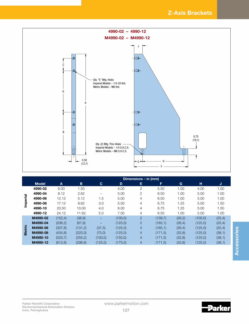
9510-9530 Series Micrometer HeadsParker Daedal micrometer heads are recommended for any application requiring micrometer accuracy in settings and adjustment. These units feature a hardened and ground spindle, easy-to-read graduations, and an attractive non-glare satin chrome finish.
Model Number FigureTravel
in (mm)Graduations
in (mm)
Dimensions – in (mm)
A B C D
Imp
eria
l
9511E A 0.50 0.001 2.03 0.50 0.187 —
9512E B 0.50 0.001 2.63 0.50 0.375 0.54
9524E B 1.00 0.001 4,23 0.75 0.625 0.73
9526E B 2.00 0.001 6.16 1.25 0.625 0.739531E C 1.00 0.0001 5.18 0.94 0.56 —9532E C 2.00 0.0001 7.18 1.44 0.56 —
Met
ric
9511M A (13) (0,01) (51,6) (13,0) (4,7) —9512M B (13) (0,01) (66,8) (13,0) (9,5) (13,7)9524M B (25) (0,01) (107,4) (19,0) (15,9) (18,5)9526M B (50) (0,01) (156,5) (32,0) (15,9) (18,5)9531M C (25) (0,002) (131,6) (23,9) (14,2) —9532M C (50) (0,002) (182,4) (36,6) (14,2) —
0 1 2 3 4 2.06(52,4)dia.
1.00 (25,4) dia.
CB
A(mid-travel)
0.50 (12,7) dia.
0.31(7,9)dia.
0 1 2 0 1 2 3 4
B(mid-travel)
0.53 (13,5) dia.0.14 (3,5) dia.
0.31 (7,9) dia.
A
C
B (mid-travel)
0.38 (9,5) dia.
C
A
Dia. D
0.26 (6,6) dia.
9531E, 9532E
9531M, 9532M
Figure CLarge Thimble MIcrometer Head
9512E, 9524E, 9526E
9512M, 9524M, 9526M
Figure BStandard Thimble MIcrometer Head
9511E
9511M
Figure AMini Thimble MIcrometer Head

Parker Hannifin CorporationElectromechanical Automation DivisionIrwin, Pennsylvania 129
www.parkermotion.com
Acc
esso
ries
0 1 2
0 50000
3 4
6.18 (157,0)(mid-travel)
1.75(44,4)
0.375 - 40 threadOFF HOLD MODE
Drive Mechanisms
9550 Series Digital Micrometer HeadsModel 9551
The 9551 precision electronic digital micrometer head provides an LCD readout to 0.00005 inch resolution. The micrometer features:
• Incremental and/or absolute positioning modes• Zero set at any position, inch and millimeter readout
(0.001 mm resolution), display hold, and automatic shutdown after two hours to conserve the integral battery
• 1.00 inch micrometer travel• Battery powered for 500 hours of use
Model 9552
The 9552 precision electronic digital micrometer offers a 0 – 2 inch travel range with a 0.00005 inch resolution. Features include:
• 2 inch spindle• Display face swivels for easy reading at various angles• Non-rotating spindle• Pre-set, zero, and inch/mm• Carbide tipped measuring face• Battery powered for 5,000 hours of use
9560 Series Differential ScrewsModel 9560: 0.75 in Range
The 9560 differential screw offers two linear adjustment ranges in one unit: a coarse adjustment range of 0.31 in (8 mm) with a 48-pitch thread and a fine adjustment range of 0.078 in (2 mm) with a pitch equal to 336 threads per inch. The 9560 is interchangeable with 9511 – 9532 series micrometer heads.
9570 Series Fine Adjsutment ScrewsModel 9570: 0.75 in Range
Model 9575: 0.50 in Range
These steel adjustment screws feature a 64-pitch thread, making them ideal for applications where finer resolution is required, but positional readout is not. These screws are easily interchanged with the 9511 – 9532 series micrometer heads.
0 1 2
0 50000
3 4
4.81 (122,2)(mid-travel)
1.75(44,4)
0.375 - 40 threadOFF HOLD MODE
0.47(11,9)
0.47(11,9)
0.50 dia.(12,7)
1.10(27,9)
0.94(23,9)
0.374 dia(9,5)
10-64 thread
0.09 rad.(2,3)
0.374 dia(9,5)
10-64 thread
2.51(63,8)
1.39(35,3)
0.58 dia.(14,7)
Model 9570
Model 9575
2.31(58,7)
0.374 dia. (9,5)
0.31 max. (7,9)
0.76(19,3)
0.188 dia.(4,8)
0.48 dia.(12,2)
0.62 dia.(15,8)

Accessories
Parker Hannifin CorporationElectromechanical Automation Division
Irwin, Pennsylvania130
www.parkermotion.com
Optical Mounts
Optical Cell MountsModel 2350: 6.0” Diameter
Model 2355: 7.0” Diameter
Model 2360: 8.0” Diameter
Model 2365: 9.0” Diameter
Parker Daedal optical mounts are highly stable, adjustable mounts for optics up to 9” in diameter and 1.25” thick. These mounts feature precise kinematic ball pivot adjustment on two axes, with orthogonal three-point suspension.
Model 2350 Models 2355, 2360, 2365
Specifications 2350 2355 2360 2365
Optic Size Opening – in (mm) Dimension “A” Dia. max.: Thickness:
6.03 (153,1)1.00 (25,4)
7.06 (179,3)1.25 (31,75)
8.06 (204,7)1.25 (31,7)
9.06 (230,1)1.25 (31,7)
Optic Retention: Threaded retainer 3 mounting clips 3 mounting clips 3 mounting clips
Range: 5° 5° 5° 5°
Resolution: 0.5 arc-sec 0.5 arc-sec 0.5 arc-sec 0.5 arc-sec
Adjustment: 2 – 64-pitch screws 3 – 32-pitch screws 3 – 32-pitch screws 3 – 32-pitch screws
Weight: 7.5 lb (16,5 kg) 20 lb (44 kg) 20 lb (44 kg) 20 lb (44 kg)
Construction: Aluminum/stainless steel
Finish: Black anodize
5.75 (146,1)
8.00(203,2)
5.00 (127,0)
8.00 (203,2)
5.00 (127,0)Qty. (4) Mtg. Holes0.28 (7,1) dia.
Qty. (4) Mtg. Holes0.28 (7,1) dia.
4.50(114,3)
6.00 (152,4)
6.00 (152,4)
6.25(158,8)
11.25(285,8)
7.00 (177,8)
10.00 (254,0)
A
12.00 (304,8)
6.06 (153,2)

Parker Hannifin CorporationElectromechanical Automation DivisionIrwin, Pennsylvania 131
www.parkermotion.com
Acc
esso
ries
Optical Mounts
Optical Cell MountsModel 2370/2371: 10.0” Diameter
Model 2375/2376: 11.0” Diameter
Model 2380/2381: 12.0” Diameter
Parker Daedal optical mounts are highly stable, adjustable mounts for optics up to 12” in diameter and 2.0” thick. These mounts feature precise kinematic ball pivot adjustment on two axes, with orthogonal three-point suspension. Solid back models are designed to support reflective optics.
Models 2370, 2375, 2380 Models 2371, 2376, 2381
Solid Back Models Aperture Models
Specifications 2370 2375 2380 2371 2376 2381
Optic Size Opening – in (mm) Dimension “A” Dia. max.: Thickness:
10.02 (254,5)2.00 (50,8)
11.02 (379,9)2.00 (50,8)
12.02 (305,3)2.00 (50,8)
10.06 (255,5)2.00 (50,8
11.06 (280,9)2.00 (50,8
12.06 (306,3)2.00 (50,8
Optic Retention: 3 mounting clips 3 mounting clips
Range: 7° 7°
Resolution: 0.5 arc-sec 0.5 arc-sec
Adjustment: 3 – 32-pitch screws 3 – 32-pitch screws
Weight: 45 lb (99 kg) 41 lb (90 kg)
Construction: Aluminum/stainless steel Aluminum/stainless steel
Finish: Black anodize Black anodize
12.02 (203,2) 12.02 (203,2)
14.75(374,7)
14.75(374,7)
8.00(203,2)
8.00(203,2)
8.00(203,2)
12.00(304,8)
16.00(406,4)
12.00(304,8)
16.00(406,4)
6.00(152,4)
8.00(203,2)
6.00(152,4)
Qty (4) holes0.53 (13,5) dia.
Qty (4) holes0.53 (13,5) dia.
Accessories
Parker Hannifin CorporationElectromechanical Automation Division
Irwin, Pennsylvania132
www.parkermotion.com
Optical Mounts
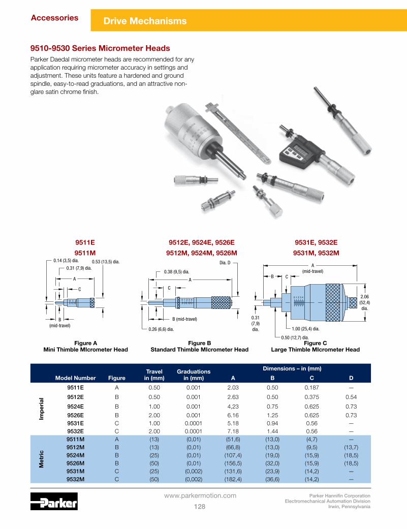
Mirror MountsModel 5000/5100: 3.0” Square Mounting Surface
Model 5300/5700: 4.5” Square Mounting Surface
Model 5800/5900: 6.0” Square Mounting Surface
Parker Daedal mirror mounts are patterned with 1/4-20 holes on 0.5” or 1.0” centers to mount mirrors and other hardware. All models except the 5800 have two fine resolution 64-pitch adjustment screws to provide precise tilting of the mounting surface in two axes. The 5800 is equipped with three adjustment screws to provide precise tilting in two axes.
Models 5000, 5300 Models 5100, 5700, 5900
Angled Base Models Flat Base Models
Specifications 5000 5300 5800 5100 5700 5900Mounting Surface Size (Square) – in (mm) Holes – (Qty. x Center)
3.0 (76,2)21 x 0.50”
4.5 (114,3) 49 x 0.50”
6.0 (152,4)25 x 1.0”
3.0 (76,2)21 x 0.50”
4.5 (114,3) 49 x 0.50”
6.0 (152,4)25 x 1.0”
Range: 12° 8° 4° 12° 8° 4°Resolution: 1.0 arc-sec 0.75 arc-sec 0.5 arc-sec 1.0 arc-sec 0.75 arc-sec 0.5 arc-secWeight – lb (kg) 1 (2,2) 2 (4,4) 4.1 (9) 0.7 (1,5) 1.6 (3,5) 3 (6,6)
Adjustment: 2 – 64-pitch screws (3 screws on 5800) 2 – 64-pitch screws Construction: Aluminum/stainless steel Aluminum/stainless steelFinish: Black anodize Black anodize
Models 5800
Dimensions – in (mm)
Model A B D D E F G5000 2.00 (50,8) 3.00 (76,2) 0.75 (19,1) 2.00 (50,8) 3.75 (95,3) 2.00 (50,8) 3.50 (88,9)5300 3.00 (76,2) 4.50 (114,3) 1.25 (31,8) 4.00 (101,6) 4.50 (114,3) 2.88 (73,2) 5.12 (130,1)5100 0.69 (17,5) 3.00 (76,2) 1.50 (38,1) 2.25 (57,2) 2.00 (50,8) 3.50 (88,9) 0 . 2 5 ( 6 , 4 )5700 0.69 (17,5) 4.50 (114,3) 3.00 (76,2) 3.75 (95,3) 2.88 (73,2) 5.12 (130,1) 0 . 2 5 ( 6 , 4 )5900 0 . 8 8 ( 2 , 4 ) 6.00 (152,4) 4.00 (101,6) 5.38 (136,7) 3.25 (82,6) 6.25 (158,8) 0 . 3 1 ( 7 , 9 )
1/4-20 thd.
1/4-20 thd. 1/4-20 thd.
5/16-18 thd. Ctr’d (Model 5100 only)1/4-20 thd. Ctr’d (Model 5900 only)
Qty. (2) Mtg. Holes1/4-20 thd.
Qty. (2) Mtg. Holes0.28 (7,1) dia.
Qty. (2) Mtg. Holes0.28 (7,1) dia.
BSquare
BSquare
A
C
F
D
E
GG
A CD
EF
6.00(152,4)
6.00 (152,4)
3.00(76,2)
3.00(76,2)
4.00(101,6)
6.75(171,5)

Parker Hannifin CorporationElectromechanical Automation DivisionIrwin, Pennsylvania 133
www.parkermotion.com
Eng
inee
ring
R
efer
ence
Linear Slides and Positioners Product Specifications
TravelThe travel listed is the total travel of the positioner from hard stop to hard stop.
Bearing Load Capacity
Normal Load
This is the maximum downward (compression) load or force which can be applied to the positioner perpendicular to the mounting surface. The center of force or the C.G. of the load must be located in the center of the mounting surface. For loads which are offset from this position, refer to moment loads.
Inverted Load
Same as a normal load except in an upward (tension) direction.
Moment Load
This refers to forces which are offset (cantilevered) from the bearing centers and therefore producing uneven loading on the bearings. This uneven loading means that some bearings are supporting more of the load than others. For this reason it is very important to determine if the moment loading for a given positioner is within acceptable limits. These moment forces are categorized by the direction they act in Pitch, Roll or Yaw; see diagram at left. When loading results in moments acting in only one of the moment directions (pitch, roll or yaw) it is called a single direction moment. Examples of this type of loading are shown below. How to calculate the maximum allowable moment load is discussed on the following page.
Pitch Moment Roll Moment Compound Pitch/Roll Moment
LoadLoad
lloRhctiP
Yaw
Thrust Capacity Thrust capacity is the maximum force or load which can be applied in the direction of travel without damage to positioning stage components.
Ta and Tb Thrust Capacity for Micrometer, Fine Screw and Differential Screw Drives
With these types of drives the mounting surface or stage carriage is pressed against the drive mechanism by means of a spring. Because of this the maximum thrust which the stage assembly can maintain is different when pressing toward the spring or away from it. When pressing toward the spring, the force is taken up by the drive mechanism (i.e. micrometer). While pulling away, the force is being held in place by the spring. Stages with this type of mechanism have two thrust capacity specifications (Ta and Tb). Ta refers to the load capacity against the micrometer and Tb is the spring load capacity. Refer to specific product drawings for load direction.
Screw Drive Thrust Capacity
Stages which use screw drive assemblies will only have one thrust capacity rating. This rating is for either direction of travel.
Straight Line and Flatness Accuracy This is the amount of error a linear positioner deviates from an ideal straight line. The straight line accuracy is the error in the horizontal plane while flatness is the error in the vertical plane. Both the straight line and the flatness accuracy are measured at the moving carriage surface center.
Thrust (Force) Tb
Thrust (Force) Ta
Flatness
Straightness

Parker Hannifin CorporationElectromechanical Automation DivisionIrwin, Pennsylvania 135
www.parkermotion.com
Eng
inee
ring
R
efer
ence
Rotary Positioners Product Specifications
Main Bearing Load CapacityNormal Load
This is the load or force which can be applied in a downward direction (Compression) on the rotary stage top. The center of force or C.G. of the load must be in the center of the mounting surface. For loads which are offset from the center, refer to moment loads.
Inverted Load
Same as Normal load capacity except in an upward or tension direction.
Moment Load
This specifies the maximum overhung load or force which can be applied to the rotary stage without damaging the mechanism. (See Calculating Moment Loads, below.)
Load
Load
2.00
C.G.
CLRunout
B
A
Perfect Circle
ActualTravelPath
Concentricity = A - B
Calculating Maximum Allowable Moment Loads on Rotary PositionersTo determine if a load or force is within acceptable moment load ranges follow the steps below:
1. Calculate maximum load or force which will be applied to the Rotary stage. Include brackets, and other axes which are mounted to the rotary stage.
2. Locate the center of force or C.G. of the load.3. Measure the distance from the center of force or C.G.
to the center of the rotary stage. This is the moment arm and is designated A.
4. Locate the moment load graph for the rotary stage you are interested in (located in back of individual product section). The X axis of the graph is the Force, the Y axis is the allowable moment arm A.
5. Locate your load force on the X axis of the graph.6. Draw a vertical line from the Force location on the X
axis parallel with the Y axis.7. Find the Moment Arm distance on the Y axis. Draw a
horizontal line from this point parallel with the X axis until the vertical and horizontal lines intersect.
8. If the intersection point is below the moment curve then the stage is within acceptable limits. If the intersection point is above the moment curve a positioner with a larger normal load capacity should be selected and the above steps repeated.
Example: Rotary Stage Moment Load
A load of 12 pounds is mounted to a 30008 rotary table. The illustration shows the position of the load in reference to the center of rotation on the rotary table. The load is offset 6 inches from the rotation center. (The 30008 moment load curve is shown below for this example.)
First find 12 pounds on the X axis and draw a vertical line parallel to the Y axis, next locate the moment arm distance on the Y axis. Draw a horizontal line from this point until it intersects with the vertical line. The intersection point is below the moment curve, thus the 30008 table is acceptable for this application.
30008in
0
10.00
cm
0
25,40
A(moment arm)
9.0022,86
8.0020,32
7.0017,78
6.0015,24
5.0012,70
4.0010,16
3.007,62
2.005,08
1.002,54
Load(force)
(lbs)(N)
1046
1567
2089
25111
30134
35156
40178
45200
50223
55245
60267
65289
70312
75334
6
C.G.
Maximum Output TorqueThe maximum torque which the rotary stage can produce at the carriage without damage or excess wear to the mechanisms.
ConcentricityThe maximum variance between a perfect circle and the path which the rotary stage follows. Concentricity is measured by placing a circular gauge disk on the table top and aligning it with the circular path of travel. An indicator is then placed on the gauge disk and the variance is measured as the concentricity error.
Axial RunoutMeasured at the center of rotation, axial runout is the amount of vertical motion the rotary stage moves as it rotates.