Embed Size (px)
Citation preview
ENGLISH
Cod. 2200772361 03 - Edition 05/2010 - 1
INSTRUCTION AND MAINTENANCE MANUAL
ROTARY SCREW COMPRESSOR UNITS
HP 3 - 5 - 7.5 KW 2.2 - 3.7 - 5.5
READ THIS MANUAL CAREFULLY BEFORE CARRYING OUT ANY OPERATIONS ON THE COMPRESSOR
UNIT.
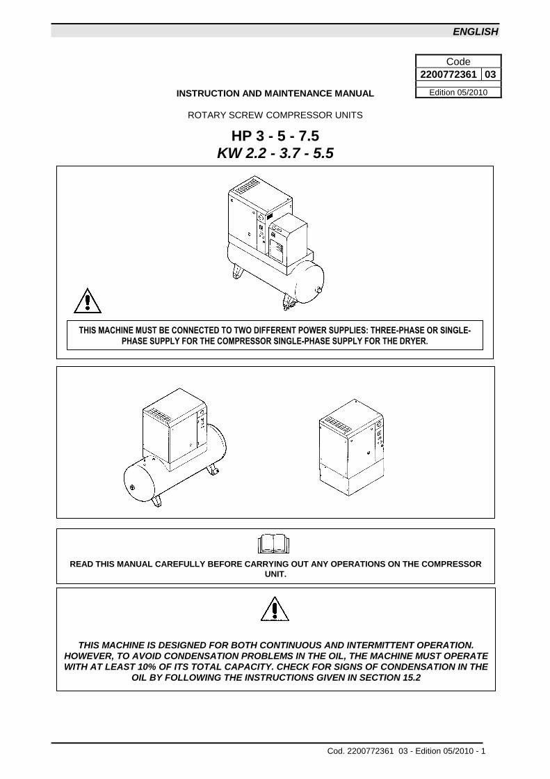
THIS MACHINE IS DESIGNED FOR BOTH CONTINUOUS AND INTERMITTENT OPERATION. HOWEVER, TO AVOID CONDENSATION PROBLEMS IN THE OIL, THE MACHINE MUST OPERATE WITH AT LEAST 10% OF ITS TOTAL CAPACITY. CHECK FOR SIGNS OF CONDENSATION IN THE
OIL BY FOLLOWING THE INSTRUCTIONS GIVEN IN SECTION 15.2
Code
2200772361 03
Edition 05/2010
THIS MACHINE MUST BE CONNECTED TO TWO DIFFERENT POWER SUPPLIES: THREE-PHASE OR SINGLE-PHASE SUPPLY FOR THE COMPRESSOR SINGLE-PHASE SUPPLY FOR THE DRYER.
ENGLISH
2 - Edition 05/2010 Cod. 2200772361 03 -
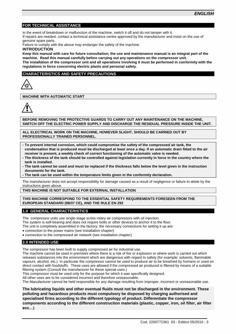
CONTENTS PART A: INFORMATION FOR THE USER 1.0 GENERAL CHARACTERISTICS 2.0 INTENDED USE 3.0 OPERATION 4.0 GENERAL SAFETY STANDARDS 5.0 DESCRIPTION OF WARNING LABELS 6.0 DANGER ZONES 7.0 SAFETY DEVICES 8.0 POSITION OF WARNING LABELS 9.0 COMPRESSOR ROOM 10.0 TRANSPORT AND HANDLING 11.0 UNPACKING 12.0 INSTALLATION 13.0 DIMENSIONS AND TECHNICAL DATA 14.0 MACHINE ILLUSTRATION 15.0 ORDINARY MAINTENANCE TO BE DONE BY THE USER 16.0 PERIODS OF INACTIVITY 17.0 SCRAPPING THE UNIT 18.0 LIST OF SPARE PARTS FOR ROUTINE MAINTENANCE 19.0 TROUBLE-SHOOTING AND EMERGENCY REPAIRS
PART B: INFORMATION RESERVED FOR TECHNICALLY SKILLED PERSONNEL 20.0 STARTING UP 21.0 GENERAL ORDINARY MAINTENANCE REQUIRES TRAINED PERSONNEL 22.0 CHANGING THE OIL 23.0 CHANGING THE OIL SEPARATING FILTER 24.0 BELT TENSION 25.0 REPLACING THE BELT 26.0 FLOW DIAGRAM 27.0 PRESSURE SWITCH ADJUSTMENT 28.0 DRYER CALIBRATION 29.0 VOLTAGE CONVERSION - WIRING DIAGRAM (ON THE BACK COVER)
IMPORTANT: A COPY OF THE WIRING DIAGRAMS CAN BE FOUND INSIDE THE ELECTRIC BOARD OF THE
COMPRESSOR.
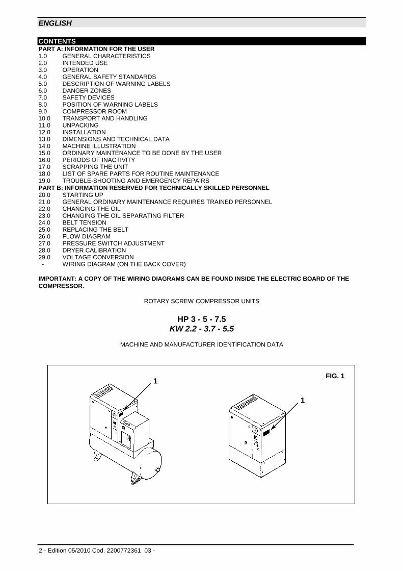
ROTARY SCREW COMPRESSOR UNITS
HP 3 - 5 - 7.5 KW 2.2 - 3.7 - 5.5
MACHINE AND MANUFACTURER IDENTIFICATION DATA
FIG. 1
1
1
ENGLISH
Cod. 2200772361 03 - Edition 05/2010 - 3
FOR TECHNICAL ASSISTANCE
In the event of breakdown or malfunction of the machine, switch it off and do not tamper with it. If repairs are needed, contact a technical assistance centre approved by the manufacturer and insist on the use of genuine spare parts. Failure to comply with the above may endanger the safety of the machine. INTRODUCTION Keep this manual with care for future consultation; the use and maintenance manual is an integral part of the
machine. Read this manual carefully before carrying out any operations on the compressor unit.
The installation of the compressor unit and all operations involving it must be performed in conformity with the
regulations in force concerning electric plants and personal safety.
CHARACTERISTICS AND SAFETY PRECAUTIONS
MACHINE WITH AUTOMATIC START
BEFORE REMOVING THE PROTECTIVE GUARDS TO CARRY OUT ANY MAINTENANCE ON THE MACHINE,
SWITCH OFF THE ELECTRIC POWER SUPPLY AND DISCHARGE THE RESIDUAL PRESSURE INSIDE THE UNIT.
ALL ELECTRICAL WORK ON THE MACHINE, HOWEVER SLIGHT, SHOULD BE CARRIED OUT BY
PROFESSIONALLY TRAINED PERSONNEL.
- To prevent internal corrosion, which could compromise the safety of the compressed air tank, the
condensation that is produced must be discharged at least once a day. If an automatic drain fitted to the air
receiver is present, a weekly check of correct functioning of the automatic valve is needed.
- The thickness of the tank should be controlled against legislation currently in force in the country where the
tank is installed.
- The tank cannot be used and must be replaced if the thickness falls below the level given in the instruction
documents for the tank.
- The tank can be used within the temperature limits given in the conformity declaration.
The manufacturer does not accept responsibility for damage caused as a result of negligence or failure to abide by the instructions given above.
THIS MACHINE IS NOT SUITABLE FOR EXTERNAL INSTALLATION
THIS MACHINE CORRESPOND TO THE ESSENTIAL SAFETY REQUIREMENTS FORESEEN FROM THE
EUROPEAN STANDARD (98/37 CE), AND THE RULE EN 292
1.0 GENERAL CHARACTERISTICS
The compressor units use single-stage screw rotary air compressors with oil injection. The system is self-bearing and does not require bolts or other devices to anchor it to the floor. The unit is completely assembled in the factory; the necessary connections for setting it up are:
connection to the power mains (see installation chapter)
connection to the compressed air network (see installation chapter)
2.0 INTENDED USE
The compressor has been built to supply compressed air for industrial use. The machine cannot be used in premises where there is a risk of fire or explosion or where work is carried out which releases substances into the environment which are dangerous with regard to safety (for example: solvents, flammable vapours, alcohol, etc.). In particular the compressor cannot be used to produce air to be breathed by humans or used on direct contact with foodstuffs. These uses are allowed if the compressed air produced is filtered by means of a suitable filtering system (Consult the manufacturer for these special uses.) This compressor must be used only for the purpose for which it was specifically designed. All other uses are to be considered incorrect and therefore unreasonable. The Manufacturer cannot be held responsible for any damage resulting from improper, incorrect or unreasonable use.
The lubricating liquids and other eventual fluids must not be discharged in the environment. These
polluting and hazardous products must compulsory be disposed by charging authorised and
specialised firms according to the different typology of product. Differentiate the compressor
components according to the different construction materials (plastic, copper, iron, oil filter, air filter
ecc…)
ENGLISH
4 - Edition 05/2010 Cod. 2200772361 03 -
3.0 OPERATION
3.1 COMPRESSOR OPERATION The electric motor and the compressor unit are coupled by means of a belt transmission. The compressor unit takes in the outside air through the suction valve. The intake air is filtered by the filter cartridge fitted upstream from the intake valve. Inside the compressor unit, the air and the lubricating oil are compressed and sent to the oil separating tank where the oil is separated from the compressed air; the air is then filtered again by the oil separating cartridge to reduce the amount of suspended oil particles to a minimum. The machine is fitted with a suitable air-cooling system. The machine is protected by a special safety thermostat: if the oil temperature reaches 105 - 110 °C the machine cuts out automatically.
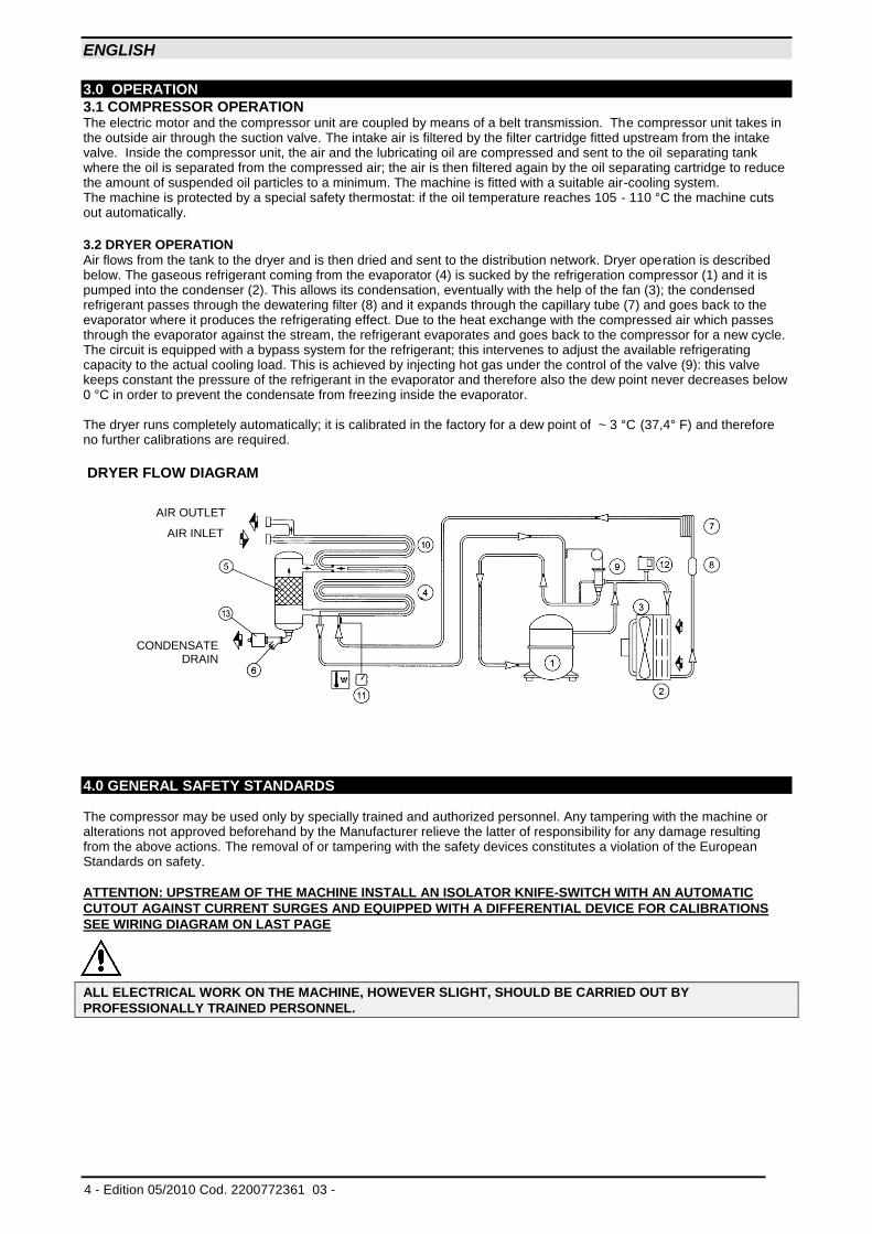
3.2 DRYER OPERATION Air flows from the tank to the dryer and is then dried and sent to the distribution network. Dryer operation is described below. The gaseous refrigerant coming from the evaporator (4) is sucked by the refrigeration compressor (1) and it is pumped into the condenser (2). This allows its condensation, eventually with the help of the fan (3); the condensed refrigerant passes through the dewatering filter (8) and it expands through the capillary tube (7) and goes back to the evaporator where it produces the refrigerating effect. Due to the heat exchange with the compressed air which passes through the evaporator against the stream, the refrigerant evaporates and goes back to the compressor for a new cycle. The circuit is equipped with a bypass system for the refrigerant; this intervenes to adjust the available refrigerating capacity to the actual cooling load. This is achieved by injecting hot gas under the control of the valve (9): this valve keeps constant the pressure of the refrigerant in the evaporator and therefore also the dew point never decreases below 0 °C in order to prevent the condensate from freezing inside the evaporator. The dryer runs completely automatically; it is calibrated in the factory for a dew point of ~ 3 °C (37,4° F) and therefore no further calibrations are required.
DRYER FLOW DIAGRAM
4.0 GENERAL SAFETY STANDARDS The compressor may be used only by specially trained and authorized personnel. Any tampering with the machine or alterations not approved beforehand by the Manufacturer relieve the latter of responsibility for any damage resulting from the above actions. The removal of or tampering with the safety devices constitutes a violation of the European Standards on safety.
ATTENTION: UPSTREAM OF THE MACHINE INSTALL AN ISOLATOR KNIFE-SWITCH WITH AN AUTOMATIC
CUTOUT AGAINST CURRENT SURGES AND EQUIPPED WITH A DIFFERENTIAL DEVICE FOR CALIBRATIONS
SEE WIRING DIAGRAM ON LAST PAGE
ALL ELECTRICAL WORK ON THE MACHINE, HOWEVER SLIGHT, SHOULD BE CARRIED OUT BY
PROFESSIONALLY TRAINED PERSONNEL.
AIR INLET
AIR OUTLET
CONDENSATE DRAIN
ENGLISH
Cod. 2200772361 03 - Edition 05/2010 - 5
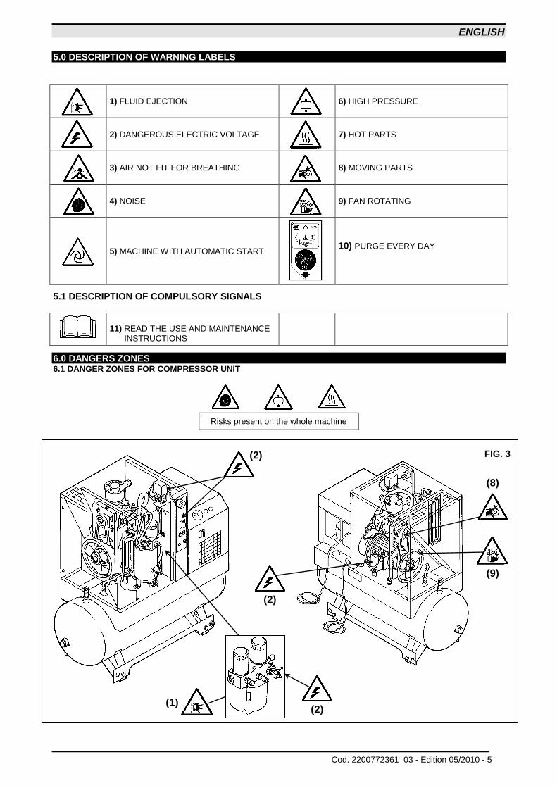
5.0 DESCRIPTION OF WARNING LABELS
1) FLUID EJECTION
6) HIGH PRESSURE
2) DANGEROUS ELECTRIC VOLTAGE
7) HOT PARTS
3) AIR NOT FIT FOR BREATHING
8) MOVING PARTS
4) NOISE
9) FAN ROTATING
5) MACHINE WITH AUTOMATIC START
10) PURGE EVERY DAY
5.1 DESCRIPTION OF COMPULSORY SIGNALS
11) READ THE USE AND MAINTENANCE INSTRUCTIONS
6.0 DANGERS ZONES 6.1 DANGER ZONES FOR COMPRESSOR UNIT
Risks present on the whole machine
FIG. 3
(2) (1)
(2)
(2)
(8)
(9)
ENGLISH
6 - Edition 05/2010 Cod. 2200772361 03 -
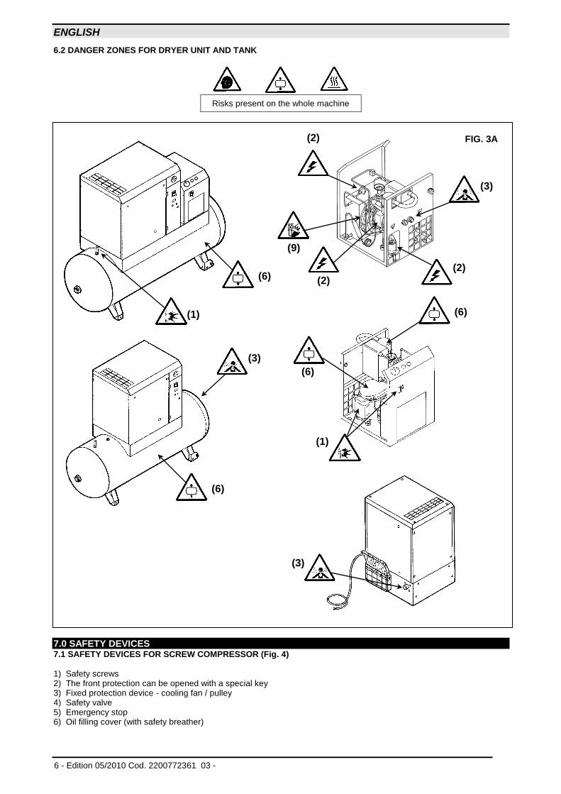
6.2 DANGER ZONES FOR DRYER UNIT AND TANK
Risks present on the whole machine
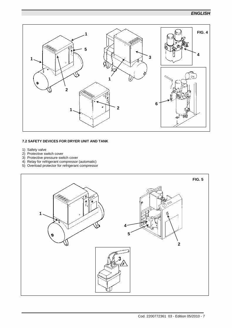
7.0 SAFETY DEVICES 7.1 SAFETY DEVICES FOR SCREW COMPRESSOR (Fig. 4) 1) Safety screws 2) The front protection can be opened with a special key 3) Fixed protection device - cooling fan / pulley 4) Safety valve 5) Emergency stop 6) Oil filling cover (with safety breather)
(3)
(6)
(9)
FIG. 3A
(1)
(2)
(2)
(2)
(6)
(1)
(3)
(6)
(6)
(3)
ENGLISH
Cod. 2200772361 03 - Edition 05/2010 - 7
7.2 SAFETY DEVICES FOR DRYER UNIT AND TANK
1) Safety valve 2) Protective switch cover 3) Protective pressure switch cover 4) Relay for refrigerant compressor (automatic) 5) Overload protector for refrigerant compressor
FIG. 5
4
5
2
1
1 4
6
FIG. 4
2
1
5
1
3
1 2
ENGLISH
8 - Edition 05/2010 Cod. 2200772361 03 -
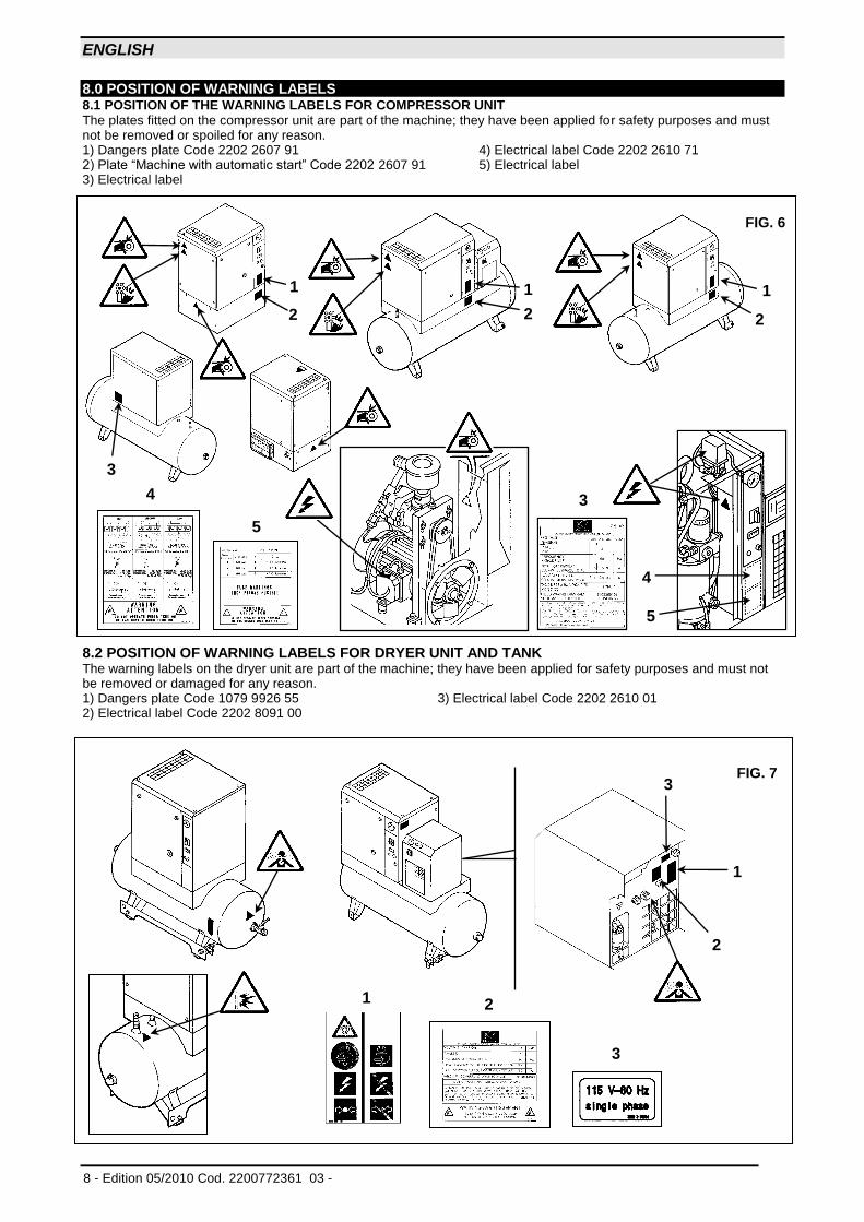
8.0 POSITION OF WARNING LABELS 8.1 POSITION OF THE WARNING LABELS FOR COMPRESSOR UNIT The plates fitted on the compressor unit are part of the machine; they have been applied for safety purposes and must not be removed or spoiled for any reason. 1) Dangers plate Code 2202 2607 91 4) Electrical label Code 2202 2610 71 2) Plate “Machine with automatic start” Code 2202 2607 91 5) Electrical label 3) Electrical label
8.2 POSITION OF WARNING LABELS FOR DRYER UNIT AND TANK The warning labels on the dryer unit are part of the machine; they have been applied for safety purposes and must not be removed or damaged for any reason. 1) Dangers plate Code 1079 9926 55 3) Electrical label Code 2202 2610 01 2) Electrical label Code 2202 8091 00
1
2
FIG. 7
1
3
2
3
FIG. 6
4
5
4
5
3
1
2
3
1
2
1
2
ENGLISH
Cod. 2200772361 03 - Edition 05/2010 - 9
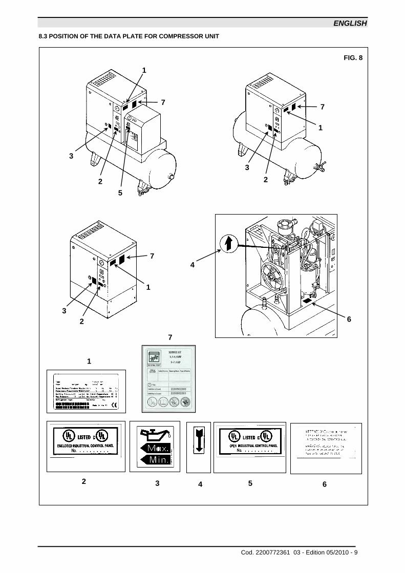
8.3 POSITION OF THE DATA PLATE FOR COMPRESSOR UNIT
6
5
4
3
FIG. 8
2
1
4
6
1
7
2
3
7
1
3
2
5
3
2
1
7
7
ENGLISH
10 - Edition 05/2010 Cod. 2200772361 03 -
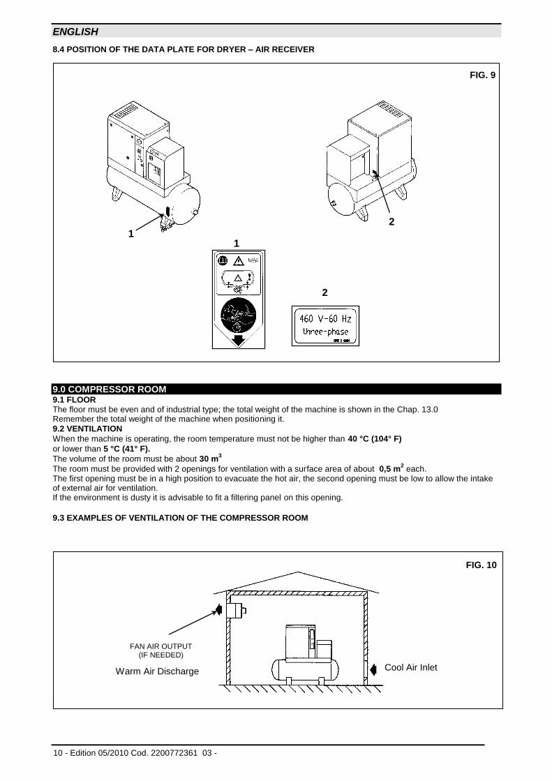
8.4 POSITION OF THE DATA PLATE FOR DRYER – AIR RECEIVER
9.0 COMPRESSOR ROOM 9.1 FLOOR The floor must be even and of industrial type; the total weight of the machine is shown in the Chap. 13.0 Remember the total weight of the machine when positioning it.
9.2 VENTILATION
When the machine is operating, the room temperature must not be higher than 40 °C (104° F)
or lower than 5 °C (41° F).
The volume of the room must be about 30 m3
The room must be provided with 2 openings for ventilation with a surface area of about 0,5 m2 each.
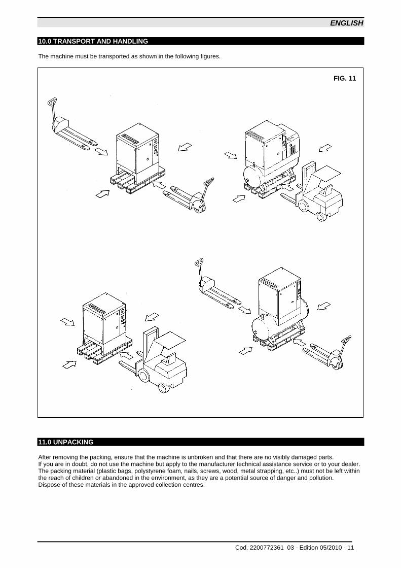
The first opening must be in a high position to evacuate the hot air, the second opening must be low to allow the intake of external air for ventilation. If the environment is dusty it is advisable to fit a filtering panel on this opening. 9.3 EXAMPLES OF VENTILATION OF THE COMPRESSOR ROOM
FAN AIR OUTPUT (IF NEEDED)
FIG. 10
Cool Air Inlet Warm Air Discharge
2
1
FIG. 9
1
2
ENGLISH
Cod. 2200772361 03 - Edition 05/2010 - 11
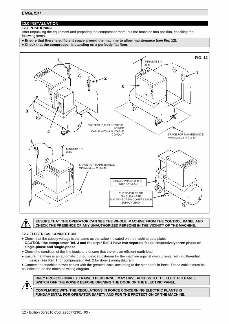
10.0 TRANSPORT AND HANDLING The machine must be transported as shown in the following figures.
11.0 UNPACKING After removing the packing, ensure that the machine is unbroken and that there are no visibly damaged parts. If you are in doubt, do not use the machine but apply to the manufacturer technical assistance service or to your dealer. The packing material (plastic bags, polystyrene foam, nails, screws, wood, metal strapping, etc..) must not be left within the reach of children or abandoned in the environment, as they are a potential source of danger and pollution. Dispose of these materials in the approved collection centres.
FIG. 11
ENGLISH
12 - Edition 05/2010 Cod. 2200772361 03 -
12.0 INSTALLATION 12.1 POSITIONING After unpacking the equipment and preparing the compressor room, put the machine into position, checking the following items:
● Ensure that there is sufficient space around the machine to allow maintenance (see Fig. 12).
● Check that the compressor is standing on a perfectly flat floor.
ENSURE THAT THE OPERATOR CAN SEE THE WHOLE MACHINE FROM THE CONTROL PANEL AND
CHECK THE PRESENCE OF ANY UNAUTHORIZED PERSONS IN THE VICINITY OF THE MACHINE.
12.2 ELECTRICAL CONNECTION
Check that the supply voltage is the same as the value indicated on the machine data plate.
CAUTION: the compressor Ref. 3 and the dryer Ref. 4 have two separate feeds, respectively three-phase or
single-phase and single-phase.
Check the condition of the line leads and ensure that there is an efficient earth lead.
Ensure that there is an automatic cut-out device upstream for the machine against overcurrents, with a differential device (see Ref. 1 for compresseur Ref. 2 for dryer ) wiring diagram.
Connect the machine power cables with the greatest care, according to the standards in force. These cables must be as indicated on the machine wiring diagram.
ONLY PROFESSIONALLY TRAINED PERSONNEL MAY HAVE ACCESS TO THE ELECTRIC PANEL.
SWITCH OFF THE POWER BEFORE OPENING THE DOOR OF THE ELECTRIC PANEL.
COMPLIANCE WITH THE REGULATIONS IN FORCE CONCERNING ELECTRIC PLANTS IS
FUNDAMENTAL FOR OPERATOR SAFETY AND FOR THE PROTECTION OF THE MACHINE.
1
SPACE FOR MAINTENANCE MINIMUM 1.5 m (4.5 ft)
FIG. 12
PROTECT THE ELECTRICAL POWER
CABLE WITH A SUITABLE CONDUIT
1
2
3
3
4
MINIMUM 2 m (6 ft)
SINGLE-PHASE DRYER SUPPLY LEAD
THREE-PHASE OR SINGLE-PHASE
ROTARY SCREW COMPRESSOR SUPPLY LEAD.
MINIMUM 2 m (6 ft)
1
SPACE FOR MAINTENANCE MINIMUM 1.5 m (4.5 ft)
ENGLISH
Cod. 2200772361 03 - Edition 05/2010 - 13
CABLES, PLUGS AND ALL OTHER TYPE OF ELECTRIC MATERIAL USED FOR THE CONNECTION MUST BE
SUITABLE FOR THE USE AND COMPLYING WITH THE REQUIREMENTS STATED BY THE REGULATIONS IN
FORCE.
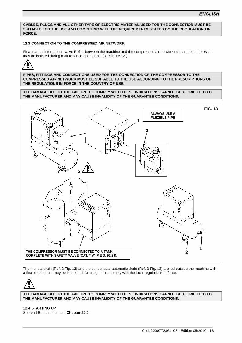
12.3 CONNECTION TO THE COMPRESSED AIR NETWORK Fit a manual interception valve Ref. 1 between the machine and the compressed air network so that the compressor may be isolated during maintenance operations; (see figure 13 ) .
PIPES, FITTINGS AND CONNECTIONS USED FOR THE CONNECTION OF THE COMPRESSOR TO THE
COMPRESSED AIR NETWORK MUST BE SUITABLE TO THE USE ACCORDING TO THE PRESCRIPTIONS OF
THE REGULATIONS IN FORCE IN THE COUNTRY OF USE.
ALL DAMAGE DUE TO THE FAILURE TO COMPLY WITH THESE INDICATIONS CANNOT BE ATTRIBUTED TO
THE MANUFACTURER AND MAY CAUSE INVALIDITY OF THE GUARANTEE CONDITIONS.
The manual drain (Ref. 2 Fig. 13) and the condensate automatic drain (Ref. 3 Fig. 13) are led outside the machine with a flexible pipe that may be inspected. Drainage must comply with the local regulations in force.
ALL DAMAGE DUE TO THE FAILURE TO COMPLY WITH THESE INDICATIONS CANNOT BE ATTRIBUTED TO
THE MANUFACTURER AND MAY CAUSE INVALIDITY OF THE GUARANTEE CONDITIONS.
12.4 STARTING UP
See part B of this manual, Chapter 20.0
1
3
2
2
1
ALWAYS USE A
FLEXIBLE PIPE
FIG. 13
1
THE COMPRESSOR MUST BE CONNECTED TO A TANK
COMPLETE WITH SAFETY VALVE (CAT. “IV” P.E.D. 97/23).
ENGLISH
14 - Edition 05/2010 Cod. 2200772361 03 -
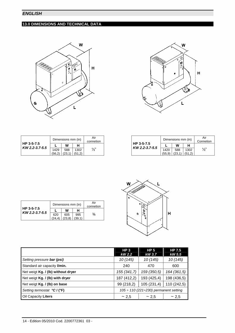
13.0 DIMENSIONS AND TECHNICAL DATA
HP 3-5-7.5
KW 2.2-3.7-5.5
Dimensions mm (in) Air
connetion
HP 3-5-7.5
KW 2.2-3.7-5.5
Dimensions mm (in) Air Connetion
L W H ½”
L W H ½” 1429
(56,2) 588
(23,1) 1302 (51,2)
1420 (55,9)
588 (23,1)
1302 (51,2)
HP 3-5-7.5
KW 2.2-3.7-5.5
Dimensions mm (in) Air
connetion
L W H ¾ 620
(24,4) 605
(23,8) 995
(39,1)
HP 3
kW 2.2
HP 5
kW 3.7
HP 7.5
kW 5.5
Setting pressure bar (psi) 10 (145) 10 (145) 10 (145)
Standard air capacity l/min. 240 470 600
Net weigt Kg. / (lb) without dryer 155 (341,7) 159 (350,5) 164 (361,5)
Net weigt Kg. / (lb) with dryer 187 (412,2) 193 (425,4) 198 (436,5)
Net weigt Kg. / (lb) on base 99 (218,2) 105 (231,4) 110 (242,5)
Setting termostat °C / (°F) 105 ÷ 110 (221÷230) permanent setting
Oil Capacity Liters ~ 2,5 ~ 2,5 ~ 2,5
ENGLISH
Cod. 2200772361 03 - Edition 05/2010 - 15
TYPE
DRYER
Weight Kg. (lb)
R 134a
Kg. (lb)
Nominal
Power W
bar - psi
MAX.
50 Hz 60 Hz 50 Hz 60 Hz 50 Hz 60 Hz 50 Hz 60 Hz
A 1 19
(41,8) 0,180
(0,39)
132w 26w 159w bar 13
(188,5)
Reference conditions: Ambient temperature 25 °C (77° F) Inlet air temperature 35 °C (95° F) Pressure 7 bar (psi 101,5) Dew point in pressure 3 °C (37,4° F)
Limit conditions: Max. ambient temperature 43°C (109,4° F) Min. ambient temperature 5°C (41° F) Max. inlet air temperature 55°C (131° F) Max. working pressure 13 bar (psi 188,5)
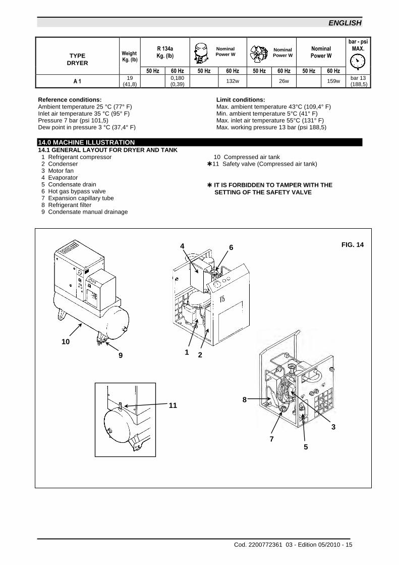
14.0 MACHINE ILLUSTRATION 14.1 GENERAL LAYOUT FOR DRYER AND TANK 1 Refrigerant compressor 2 Condenser 3 Motor fan 4 Evaporator 5 Condensate drain 6 Hot gas bypass valve 7 Expansion capillary tube 8 Refrigerant filter 9 Condensate manual drainage
10 Compressed air tank 11 Safety valve (Compressed air tank)
IT IS FORBIDDEN TO TAMPER WITH THE
SETTING OF THE SAFETY VALVE
Nominal
Power W
Nominal
Power W
FIG. 14
11
5 7
9 1 2
3
4 6
8
10
ENGLISH
16 - Edition 05/2010 Cod. 2200772361 03 -
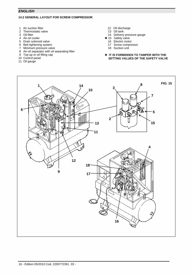
14.2 GENERAL LAYOUT FOR SCREW COMPRESSOR
1 Air suction filter 2 Thermostatic valve 3 Oil filter 4 Air-oil cooler 5 Drain solenoid valve 6 Belt tightening system 7 Minimum pressure valve 8 Air-oil separator with oil separating filter 9 Top-up or oil filling cap 10 Control panel 11 Oil gauge
12 Oil discharge 13 Oil tank 14 Delivery pressure gauge 15 Safety valve 16 Electric motor 17 Screw compressor 18 Suction unit
IT IS FORBIDDEN TO TAMPER WITH THE
SETTING VALUES OF THE SAFETY VALVE
FIG. 15
9
3 8
7
5
15 2
1
6
14
10
13
11
12
4
18
17
16
ENGLISH
Cod. 2200772361 03 - Edition 05/2010 - 17
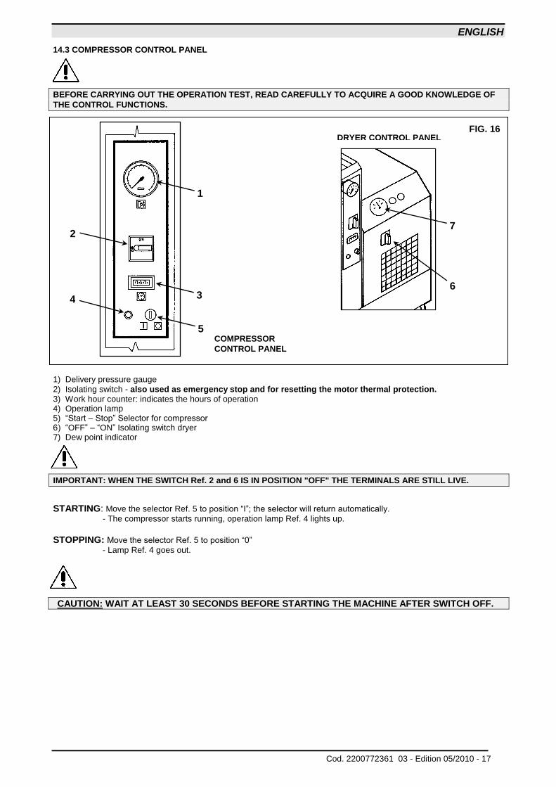
14.3 COMPRESSOR CONTROL PANEL
BEFORE CARRYING OUT THE OPERATION TEST, READ CAREFULLY TO ACQUIRE A GOOD KNOWLEDGE OF
THE CONTROL FUNCTIONS.
1) Delivery pressure gauge
2) Isolating switch - also used as emergency stop and for resetting the motor thermal protection. 3) Work hour counter: indicates the hours of operation 4) Operation lamp 5) “Start – Stop” Selector for compressor 6) “OFF” – “ON” Isolating switch dryer 7) Dew point indicator
IMPORTANT: WHEN THE SWITCH Ref. 2 and 6 IS IN POSITION "OFF" THE TERMINALS ARE STILL LIVE.
STARTING: Move the selector Ref. 5 to position “I”; the selector will return automatically.
- The compressor starts running, operation lamp Ref. 4 lights up.
STOPPING: Move the selector Ref. 5 to position “0”
- Lamp Ref. 4 goes out.
CAUTION: WAIT AT LEAST 30 SECONDS BEFORE STARTING THE MACHINE AFTER SWITCH OFF.
COMPRESSOR
CONTROL PANEL
FIG. 16 DRYER CONTROL PANEL
6
7
1
2
3 4
5
ENGLISH
18 - Edition 05/2010 Cod. 2200772361 03 -
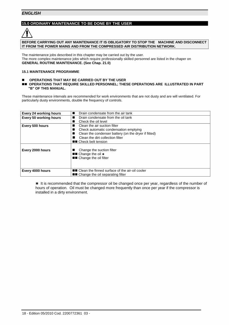
15.0 ORDINARY MAINTENANCE TO BE DONE BY THE USER
BEFORE CARRYING OUT ANY MAINTENANCE IT IS OBLIGATORY TO STOP THE MACHINE AND DISCONNECT
IT FROM THE POWER MAINS AND FROM THE COMPRESSED AIR DISTRIBUTION NETWORK.
The maintenance jobs described in this chapter may be carried out by the user. The more complex maintenance jobs which require professionally skilled personnel are listed in the chaper on
GENERAL ROUTINE MAINTENANCE. (See Chap. 21.0)
15.1 MAINTENANCE PROGRAMME
OPERATIONS THAT MAY BE CARRIED OUT BY THE USER
OPERATIONS THAT REQUIRE SKILLED PERSONNEL; THESE OPERATIONS ARE ILLUSTRATED IN PART
"B" OF THIS MANUAL. These maintenance intervals are recommended for work environments that are not dusty and are will ventilated. For particularly dusty environments, double the frequency of controls.
Every 24 working hours Drain condensate from the air tank
Every 50 working hours Drain condensate from the oil tank Check the oil level
Every 500 hours Clean the air suction filter Check automatic condensation emptying Clean the condenser battery (on the dryer if fitted)
Clean the dirt collection filter Check belt tension
Every 2000 hours Change the suction filter Change the oil Change the oil filter
Every 4000 hours Clean the finned surface of the air-oil cooler
Change the oil separating filter
It is recommended that the compressor oil be changed once per year, regardless of the number of hours of operation. Oil must be changed more frequently than once per year if the compressor is installed in a dirty environment.
ENGLISH
Cod. 2200772361 03 - Edition 05/2010 - 19
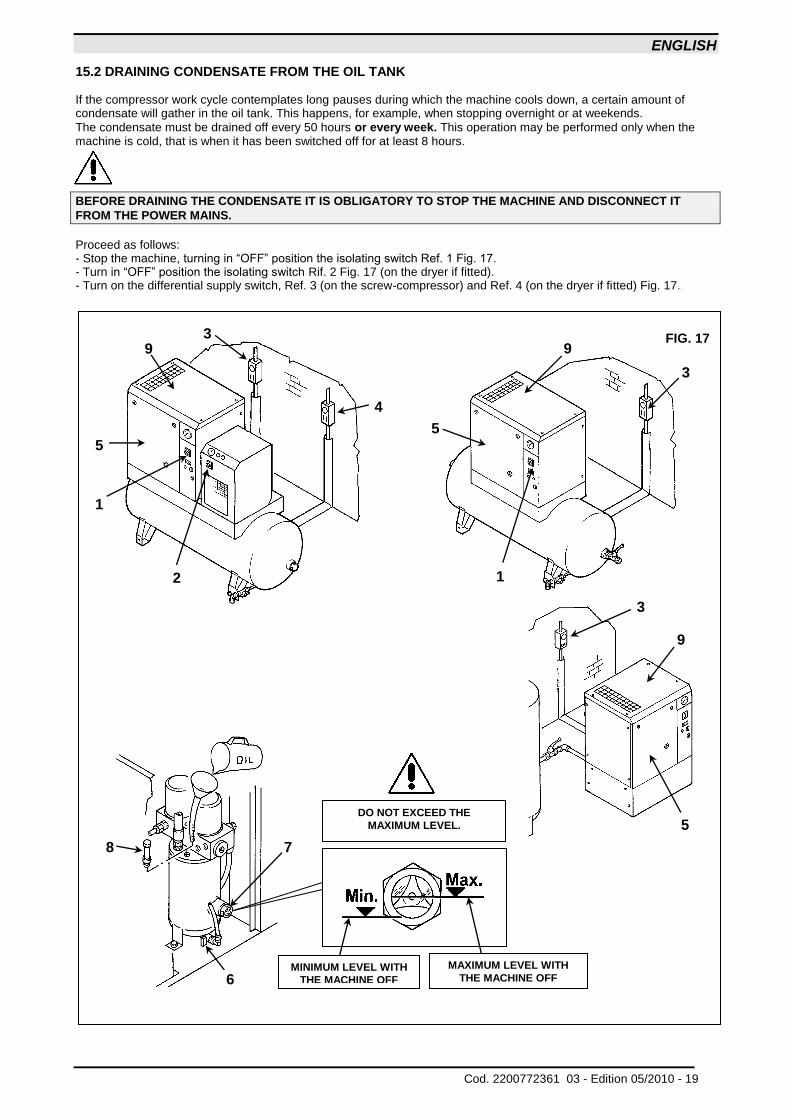
15.2 DRAINING CONDENSATE FROM THE OIL TANK If the compressor work cycle contemplates long pauses during which the machine cools down, a certain amount of condensate will gather in the oil tank. This happens, for example, when stopping overnight or at weekends.
The condensate must be drained off every 50 hours or every week. This operation may be performed only when the machine is cold, that is when it has been switched off for at least 8 hours.
BEFORE DRAINING THE CONDENSATE IT IS OBLIGATORY TO STOP THE MACHINE AND DISCONNECT IT
FROM THE POWER MAINS.
Proceed as follows: - Stop the machine, turning in “OFF” position the isolating switch Ref. 1 Fig. 17. - Turn in “OFF” position the isolating switch Rif. 2 Fig. 17 (on the dryer if fitted). - Turn on the differential supply switch, Ref. 3 (on the screw-compressor) and Ref. 4 (on the dryer if fitted) Fig. 17.
FIG. 17
8 7
6
DO NOT EXCEED THE
MAXIMUM LEVEL.
MAXIMUM LEVEL WITH
THE MACHINE OFF
MINIMUM LEVEL WITH
THE MACHINE OFF
4
3 9
5
1
2
3
9
1
5
3
9
5
ENGLISH
20 - Edition 05/2010 Cod. 2200772361 03 -
- Wait for the machine to cool down. - Remove the panel Ref. 5 Fig. 17 with the key provided. - SLOWLY turn on the tap Ref. 6 Fig. 17 and let the condensate flow out. - When the first traces of oil appear, turn off the tap.
CONDENSATE MUST BE DISPOSED OF IN CONFORMITY WITH THE LOCAL REGULATIONS IN FORCE.
- Check the oil level on the indicator Ref. 7 Fig. 17.
- If the oil level is under the minimum, top up as described at point 15.3.
USE OIL OF THE SAME TYPE AS THAT ALREADY IN THE MACHINE; DO NOT MIX DIFFERENT TYPES OF OIL
15.3 CHECK OIL LEVEL AND TOP UP
- Stop the machine, turning in “OFF” position the isolating switch Ref. 1 Fig. 17.
- WAIT A FEW MINUTES FOR THE FOAM IN THE OIL COLLECTOR TO ABATE. - Check the oil level on the indicator Ref. 7 Fig. 17.
- If the oil level is below minimum, fill up as follows - Turn in “OFF” position the isolating switch Rif. 2 Fig. 17 (on the dryer if fitted) - Turn on the differential supply switch, Ref. 3 (on the screw-compressor) and Ref. 4 (on the dryer if fitted) Fig. 17.
USE OIL OF THE SAME TYPE AS THAT ALREADY IN THE MACHINE; DO NOT MIX DIFFERENT TYPES OF OIL.
BEFORE CARRYING OUT ANY OPERATION ON THE MACHINE, ENSURE THAT THE ELECTRIC POWER SUPPLY
HAS BEEN DISCONNECTED.
- Open the front protection Ref. 5 Fig. 17 using the special key. - Remove the fixed protection device (machine cover) Ref. 9 Fig. 17. - Slowly unscrew the oil cap Ref. 8 Fig 17, ensuring there is no pressure inside. - Top up to maximum level Ref. 7 Fig. 17, with oil of the same type in the compressor. - Close the oil manifold cap Ref. 8 Fig. 17.
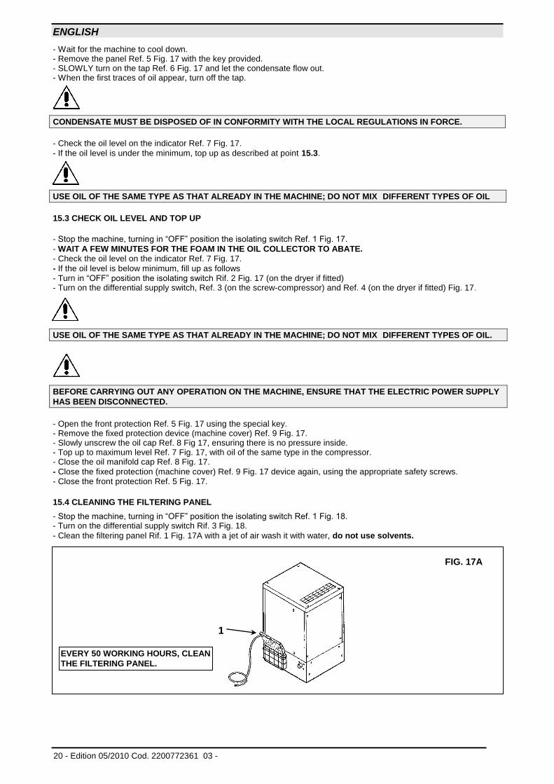
- Close the fixed protection (machine cover) Ref. 9 Fig. 17 device again, using the appropriate safety screws. - Close the front protection Ref. 5 Fig. 17. 15.4 CLEANING THE FILTERING PANEL
- Stop the machine, turning in “OFF” position the isolating switch Ref. 1 Fig. 18. - Turn on the differential supply switch Rif. 3 Fig. 18.
- Clean the filtering panel Rif. 1 Fig. 17A with a jet of air wash it with water, do not use solvents.
FIG. 17A
1
EVERY 50 WORKING HOURS, CLEAN
THE FILTERING PANEL.
ENGLISH
Cod. 2200772361 03 - Edition 05/2010 - 21
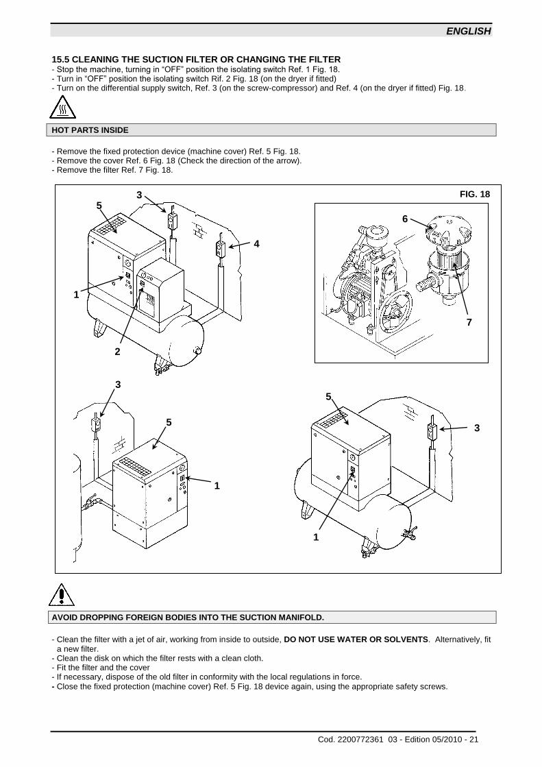
15.5 CLEANING THE SUCTION FILTER OR CHANGING THE FILTER - Stop the machine, turning in “OFF” position the isolating switch Ref. 1 Fig. 18. - Turn in “OFF” position the isolating switch Rif. 2 Fig. 18 (on the dryer if fitted) - Turn on the differential supply switch, Ref. 3 (on the screw-compressor) and Ref. 4 (on the dryer if fitted) Fig. 18.
HOT PARTS INSIDE
- Remove the fixed protection device (machine cover) Ref. 5 Fig. 18. - Remove the cover Ref. 6 Fig. 18 (Check the direction of the arrow). - Remove the filter Ref. 7 Fig. 18.
AVOID DROPPING FOREIGN BODIES INTO THE SUCTION MANIFOLD.
- Clean the filter with a jet of air, working from inside to outside, DO NOT USE WATER OR SOLVENTS. Alternatively, fit
a new filter. - Clean the disk on which the filter rests with a clean cloth. - Fit the filter and the cover - If necessary, dispose of the old filter in conformity with the local regulations in force. - Close the fixed protection (machine cover) Ref. 5 Fig. 18 device again, using the appropriate safety screws.
FIG. 18
3
7
6
3
4
5
1
2
5
1
3
5
1
ENGLISH
22 - Edition 05/2010 Cod. 2200772361 03 -
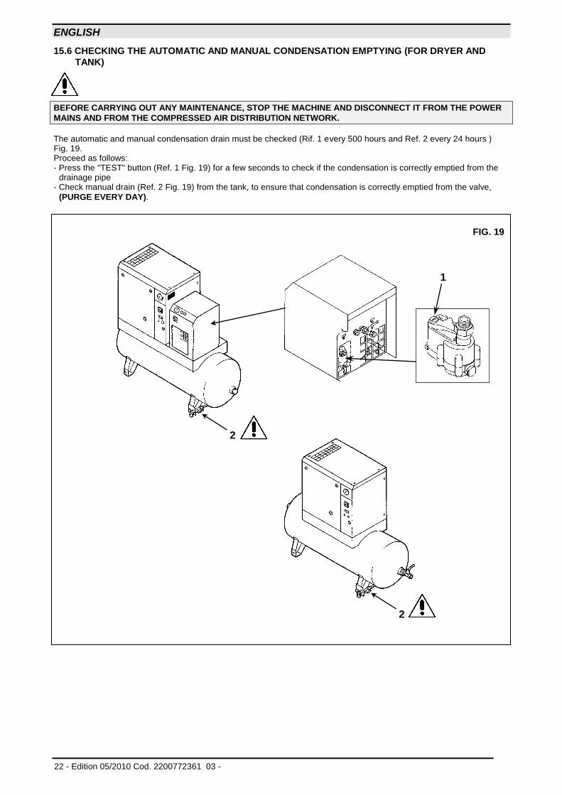
15.6 CHECKING THE AUTOMATIC AND MANUAL CONDENSATION EMPTYING (FOR DRYER AND
TANK)
BEFORE CARRYING OUT ANY MAINTENANCE, STOP THE MACHINE AND DISCONNECT IT FROM THE POWER
MAINS AND FROM THE COMPRESSED AIR DISTRIBUTION NETWORK.
The automatic and manual condensation drain must be checked (Rif. 1 every 500 hours and Ref. 2 every 24 hours ) Fig. 19. Proceed as follows: - Press the "TEST" button (Ref. 1 Fig. 19) for a few seconds to check if the condensation is correctly emptied from the
drainage pipe - Check manual drain (Ref. 2 Fig. 19) from the tank, to ensure that condensation is correctly emptied from the valve,
(PURGE EVERY DAY).
FIG. 19
2
2
1
ENGLISH
Cod. 2200772361 03 - Edition 05/2010 - 23
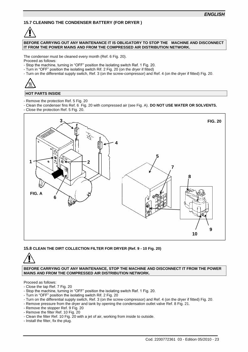
15.7 CLEANING THE CONDENSER BATTERY (FOR DRYER )
BEFORE CARRYING OUT ANY MAINTENANCE IT IS OBLIGATORY TO STOP THE MACHINE AND DISCONNECT
IT FROM THE POWER MAINS AND FROM THE COMPRESSED AIR DISTRIBUTION NETWORK.
The condenser must be cleaned every month (Ref. 6 Fig. 20). Proceed as follows: - Stop the machine, turning in “OFF” position the isolating switch Ref. 1 Fig. 20. - Turn in “OFF” position the isolating switch Rif. 2 Fig. 20 (on the dryer if fitted) - Turn on the differential supply switch, Ref. 3 (on the screw-compressor) and Ref. 4 (on the dryer if fitted) Fig. 20.
HOT PARTS INSIDE
- Remove the protection Ref. 5 Fig. 20
- Clean the condenser fins Ref. 6 Fig. 20 with compressed air (see Fig. A). DO NOT USE WATER OR SOLVENTS. - Close the protection Ref. 5 Fig. 20.
15.8 CLEAN THE DIRT COLLECTION FILTER FOR DRYER (Ref. 9 - 10 Fig. 20)
BEFORE CARRYING OUT ANY MAINTENANCE, STOP THE MACHINE AND DISCONNECT IT FROM THE POWER
MAINS AND FROM THE COMPRESSED AIR DISTRIBUTION NETWORK.
Proceed as follows: - Close the tap Ref. 7 Fig. 20 - Stop the machine, turning in “OFF” position the isolating switch Ref. 1 Fig. 20. - Turn in “OFF” position the isolating switch Rif. 2 Fig. 20 - Turn on the differential supply switch, Ref. 3 (on the screw-compressor) and Ref. 4 (on the dryer if fitted) Fig. 20. - Remove pressure from the dryer and tank by opening the condensation outlet valve Ref. 8 Fig. 21. - Remove the stopper Ref. 9 Fig. 20 - Remove the filter Ref. 10 Fig. 20 - Clean the filter Ref. 10 Fig. 20 with a jet of air, working from inside to outside. - Install the filter, fix the plug.
FIG. 20
10 9
5
6
1 2
3
4
FIG. A
7
8
ENGLISH
24 - Edition 05/2010 Cod. 2200772361 03 -
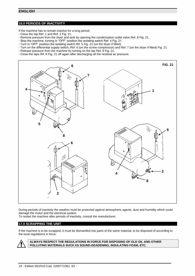
16.0 PERIODS OF INACTIVITY If the machine has to remain inactive for a long period: - Close the tap Ref. 1 and Ref. 2 Fig. 21. - Remove pressure from the dryer and tank by opening the condensation outlet valve Ref. 8 Fig. 21. - Stop the machine, turning in “OFF” position the isolating switch Ref. 4 Fig. 21. - Turn in “OFF” position the isolating switch Rif. 5 Fig. 21 (on the dryer if fitted) - Turn on the differential supply switch, Ref. 6 (on the screw-compressor) and Ref. 7 (on the dryer if fitted) Fig. 21. - Release pressure from the machine by turning on the tap Ref. 8 Fig. 21. - Close the taps Rif. 8 Fig. 21 off again after discharging all the residual air pressure.
During periods of inactivity the weather must be protected against atmospheric agents, dust and humidity which could damage the motor and the electrical system. To restart the machine after periods of inactivity, consult the manufacturer.
17.0 SCRAPPING THE UNIT If the machine is to be scrapped, it must be dismantled into parts of the same material, to be disposed of according to the local regulations in force.
ALWAYS RESPECT THE REGULATIONS IN FORCE FOR DISPOSING OF OLD OIL AND OTHER
POLLUTING MATERIALS SUCH AS SOUND-DEADENING, INSULATING FOAM, ETC.
FIG. 21
1
2
8
8
4
4
5
6
7
6
6
2
ENGLISH
Cod. 2200772361 03 - Edition 05/2010 - 25
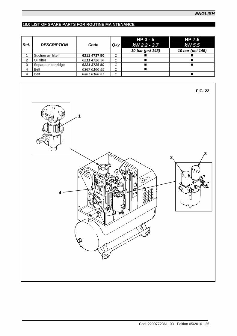
18.0 LIST OF SPARE PARTS FOR ROUTINE MAINTENANCE
Ref. DESCRIPTION Code Q.ty
HP 3 - 5 kW 2.2 - 3.7
HP 7.5 kW 5.5
10 bar (psi 145) 10 bar (psi 145)
1 Suction air filter 6211 4737 50 1
2 Oil filter 6211 4726 50 1
3 Separator cartridge 6221 3726 50 1
4 Belt 0367 0100 55 1
4 Belt 0367 0100 57 1
FIG. 22
2 3
1
4
ENGLISH
26 - Edition 05/2010 Cod. 2200772361 03 -
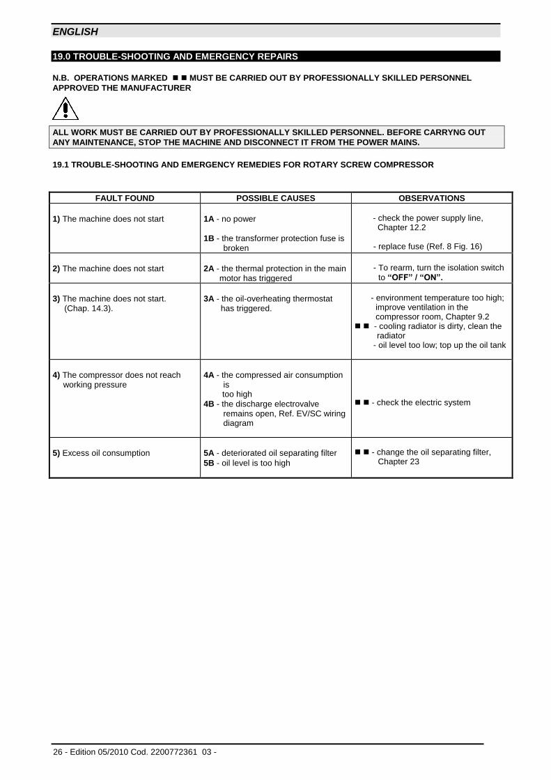
19.0 TROUBLE-SHOOTING AND EMERGENCY REPAIRS
N.B. OPERATIONS MARKED MUST BE CARRIED OUT BY PROFESSIONALLY SKILLED PERSONNEL
APPROVED THE MANUFACTURER
ALL WORK MUST BE CARRIED OUT BY PROFESSIONALLY SKILLED PERSONNEL. BEFORE CARRYNG OUT
ANY MAINTENANCE, STOP THE MACHINE AND DISCONNECT IT FROM THE POWER MAINS.
19.1 TROUBLE-SHOOTING AND EMERGENCY REMEDIES FOR ROTARY SCREW COMPRESSOR
FAULT FOUND POSSIBLE CAUSES OBSERVATIONS
1) The machine does not start
1A - no power
1B - the transformer protection fuse is broken
- check the power supply line, Chapter 12.2
- replace fuse (Ref. 8 Fig. 16)
2) The machine does not start
2A - the thermal protection in the main motor has triggered
- To rearm, turn the isolation switch
to “OFF” / “ON”.
3) The machine does not start. (Chap. 14.3).
3A - the oil-overheating thermostat has triggered.
- environment temperature too high;
improve ventilation in the compressor room, Chapter 9.2
- cooling radiator is dirty, clean the radiator
- oil level too low; top up the oil tank
4) The compressor does not reach working pressure
4A - the compressed air consumption is
too high
4B - the discharge electrovalve remains open, Ref. EV/SC wiring diagram
- check the electric system
5) Excess oil consumption
5A - deteriorated oil separating filter
5B - oil level is too high
- change the oil separating filter, Chapter 23
ENGLISH
Cod. 2200772361 03 - Edition 05/2010 - 27
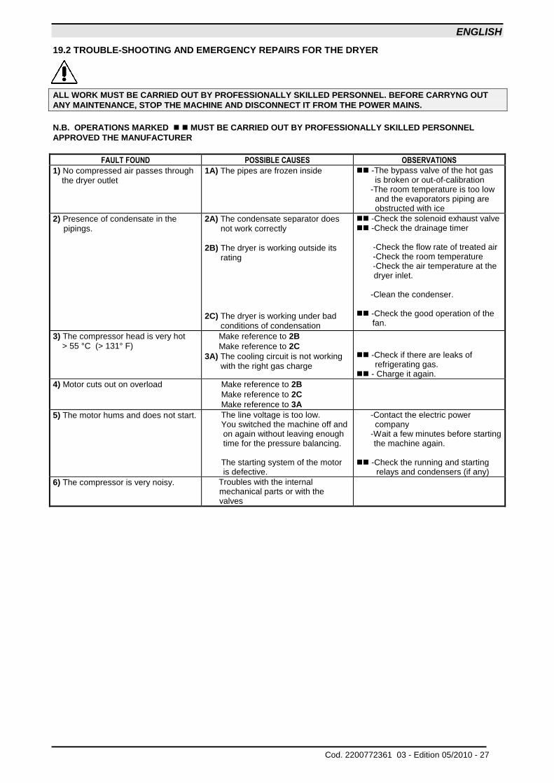
19.2 TROUBLE-SHOOTING AND EMERGENCY REPAIRS FOR THE DRYER
ALL WORK MUST BE CARRIED OUT BY PROFESSIONALLY SKILLED PERSONNEL. BEFORE CARRYNG OUT
ANY MAINTENANCE, STOP THE MACHINE AND DISCONNECT IT FROM THE POWER MAINS.
N.B. OPERATIONS MARKED MUST BE CARRIED OUT BY PROFESSIONALLY SKILLED PERSONNEL
APPROVED THE MANUFACTURER
FAULT FOUND POSSIBLE CAUSES OBSERVATIONS
1) No compressed air passes through the dryer outlet
1A) The pipes are frozen inside -The bypass valve of the hot gas is broken or out-of-calibration
-The room temperature is too low and the evaporators piping are obstructed with ice
2) Presence of condensate in the pipings.
2A) The condensate separator does not work correctly
2B) The dryer is working outside its rating
2C) The dryer is working under bad conditions of condensation
-Check the solenoid exhaust valve -Check the drainage timer -Check the flow rate of treated air -Check the room temperature -Check the air temperature at the
dryer inlet. -Clean the condenser. -Check the good operation of the
fan.
3) The compressor head is very hot > 55 °C (> 131° F)
Make reference to 2B
Make reference to 2C
3A) The cooling circuit is not working with the right gas charge
-Check if there are leaks of
refrigerating gas. - Charge it again.
4) Motor cuts out on overload Make reference to 2B
Make reference to 2C
Make reference to 3A
5) The motor hums and does not start. The line voltage is too low. You switched the machine off and
on again without leaving enough time for the pressure balancing.
The starting system of the motor
is defective.
-Contact the electric power company
-Wait a few minutes before starting the machine again.
-Check the running and starting
relays and condensers (if any)
6) The compressor is very noisy. Troubles with the internal mechanical parts or with the valves
ENGLISH
28 - Edition 05/2010 Cod. 2200772361 03 -
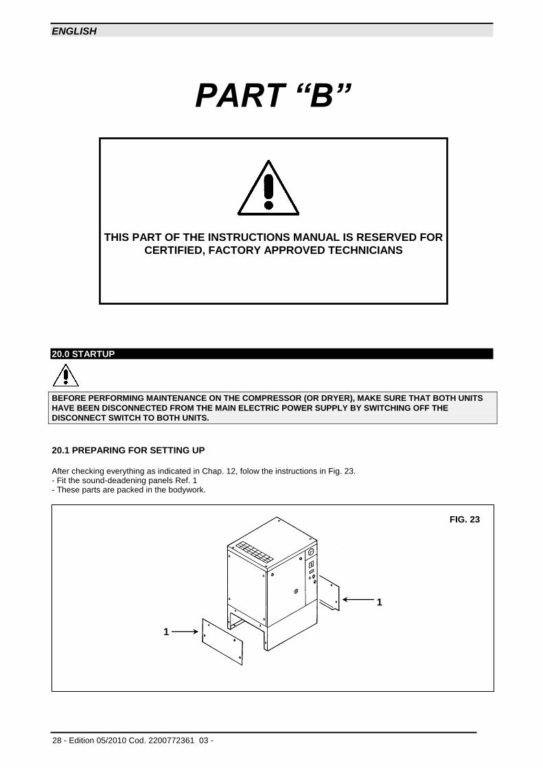
PART “B”
20.0 STARTUP
BEFORE PERFORMING MAINTENANCE ON THE COMPRESSOR (OR DRYER), MAKE SURE THAT BOTH UNITS
HAVE BEEN DISCONNECTED FROM THE MAIN ELECTRIC POWER SUPPLY BY SWITCHING OFF THE
DISCONNECT SWITCH TO BOTH UNITS.
20.1 PREPARING FOR SETTING UP
After checking everything as indicated in Chap. 12, folow the instructions in Fig. 23. - Fit the sound-deadening panels Ref. 1 - These parts are packed in the bodywork.
THIS PART OF THE INSTRUCTIONS MANUAL IS RESERVED FOR
CERTIFIED, FACTORY APPROVED TECHNICIANS
FIG. 23
1
1
ENGLISH
Cod. 2200772361 03 - Edition 05/2010 - 29
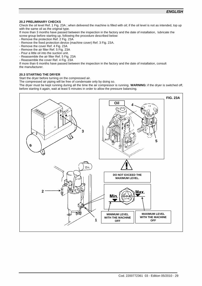
20.2 PRELIMINARY CHECKS Check the oil level Ref. 1 Fig. 23A ; when delivered the machine is filled with oil; if the oil level is not as intended, top up with the same oil as the original type. If more than 3 months have passed between the inspection in the factory and the date of installation, lubricate the screw group before starting up, following the procedure described below: - Remove the protection Ref. 2 Fig. 23A - Remove the fixed protection device (machine cover) Ref. 3 Fig. 23A. - Remove the cover Ref. 4 Fig. 23A - Remove the air filter Ref. 5 Fig. 23A - Pour a little oil into the suction unit. - Reassemble the air filter Ref. 5 Fig. 23A - Reassemble the cover Ref. 4 Fig. 23A If more than 6 months have passed between the inspection in the factory and the date of installation, consult the manufacturer. 20.3 STARTING THE DRYER Start the dryer before turning on the compressed air. The compressed air piping will be free of condensate only by doing so.
The dryer must be kept running during all the time the air compressor is running. WARNING: if the dryer is switched off, before starting it again, wait at least 5 minutes in order to allow the pressure balancing.
FIG. 23A
DO NOT EXCEED THE
MAXIMUM LEVEL.
MAXIMUM LEVEL
WITH THE MACHINE
OFF
MINIMUM LEVEL
WITH THE MACHINE
OFF
1
5
4 Oil
3
2
ENGLISH
30 - Edition 05/2010 Cod. 2200772361 03 -
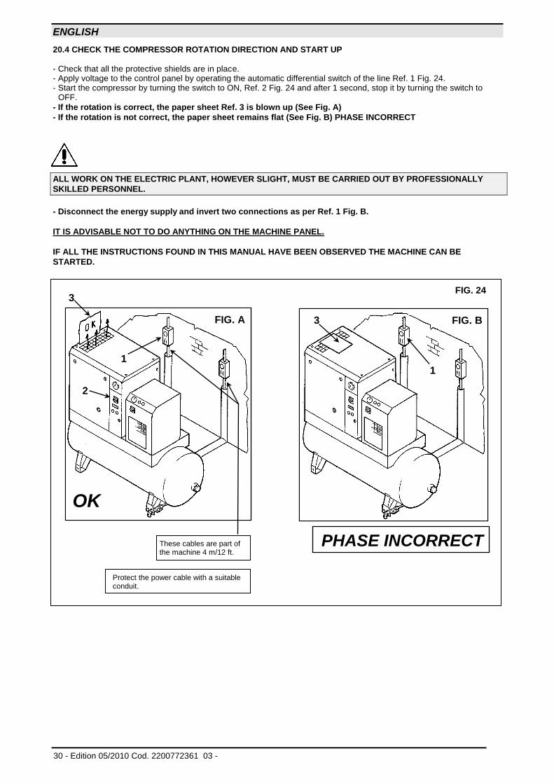
20.4 CHECK THE COMPRESSOR ROTATION DIRECTION AND START UP - Check that all the protective shields are in place. - Apply voltage to the control panel by operating the automatic differential switch of the line Ref. 1 Fig. 24. - Start the compressor by turning the switch to ON, Ref. 2 Fig. 24 and after 1 second, stop it by turning the switch to
OFF.
- If the rotation is correct, the paper sheet Ref. 3 is blown up (See Fig. A) - If the rotation is not correct, the paper sheet remains flat (See Fig. B) PHASE INCORRECT
ALL WORK ON THE ELECTRIC PLANT, HOWEVER SLIGHT, MUST BE CARRIED OUT BY PROFESSIONALLY
SKILLED PERSONNEL.
- Disconnect the energy supply and invert two connections as per Ref. 1 Fig. B.
IT IS ADVISABLE NOT TO DO ANYTHING ON THE MACHINE PANEL.
IF ALL THE INSTRUCTIONS FOUND IN THIS MANUAL HAVE BEEN OBSERVED THE MACHINE CAN BE
STARTED.
PHASE INCORRECT These cables are part of the machine 4 m/12 ft.
Protect the power cable with a suitable conduit.
OK
3
1
2
FIG. A
FIG. 24
1
3 FIG. B
ENGLISH
Cod. 2200772361 03 - Edition 05/2010 - 31
21.0 MAINTENANCE REQUIRES COMPLETE KNOWLEDGE AND UNDERSTANDING OF
COMPRESSOR OPERATION AND MAINTENANCE
BEFORE PERFORMING ANY MAINTENANCE PROCEDURES, IT IS NECESSARY TO STOP BOTH THE
COMPRESSOR AND DRYER, AND DISCONNECT BOTH UNITS FROM THE MAIN POWER SUPPLY AND CLOSE
THE AIR VALVE TO THE AIR SYSTEM.
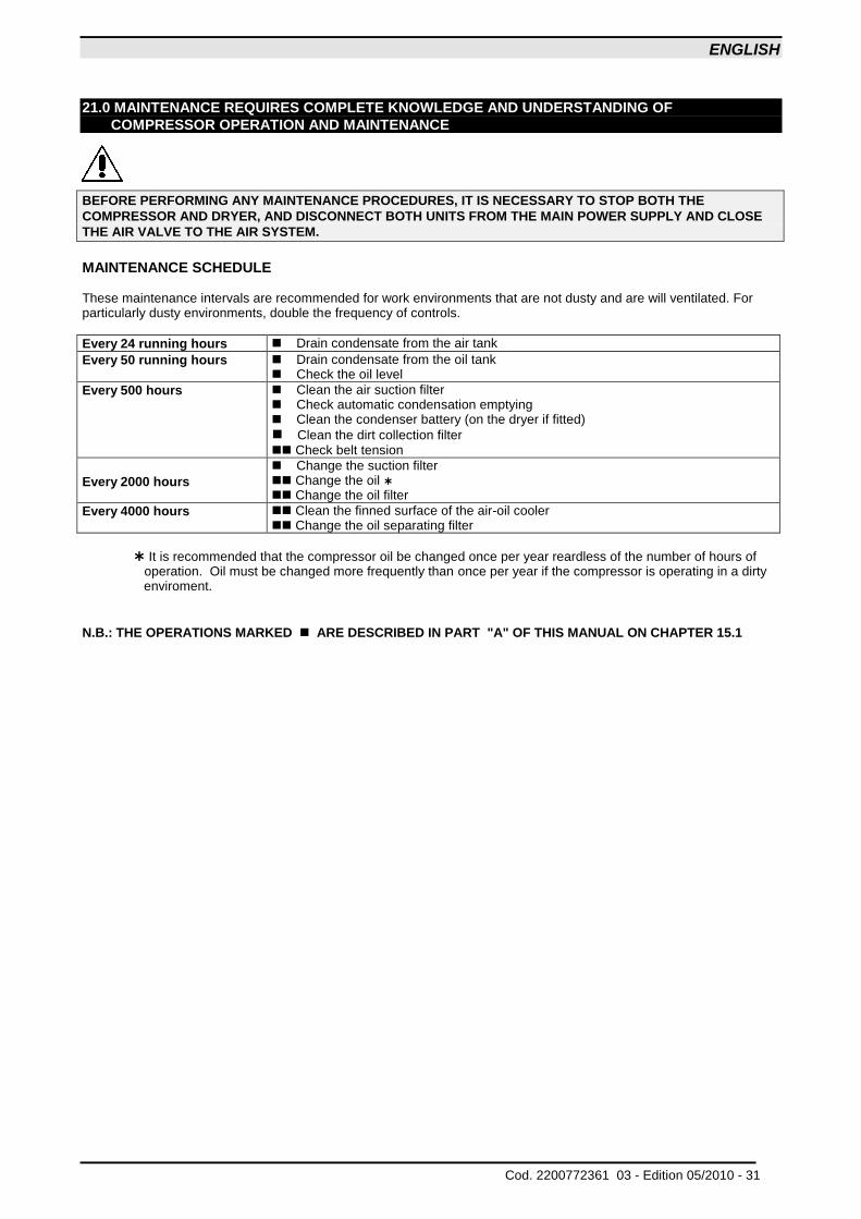
MAINTENANCE SCHEDULE These maintenance intervals are recommended for work environments that are not dusty and are will ventilated. For particularly dusty environments, double the frequency of controls.
Every 24 running hours Drain condensate from the air tank
Every 50 running hours Drain condensate from the oil tank Check the oil level
Every 500 hours Clean the air suction filter Check automatic condensation emptying Clean the condenser battery (on the dryer if fitted)
Clean the dirt collection filter Check belt tension
Every 2000 hours Change the suction filter Change the oil Change the oil filter
Every 4000 hours Clean the finned surface of the air-oil cooler Change the oil separating filter
It is recommended that the compressor oil be changed once per year reardless of the number of hours of
operation. Oil must be changed more frequently than once per year if the compressor is operating in a dirty enviroment.
N.B.: THE OPERATIONS MARKED ARE DESCRIBED IN PART "A" OF THIS MANUAL ON CHAPTER 15.1
ENGLISH
32 - Edition 05/2010 Cod. 2200772361 03 -
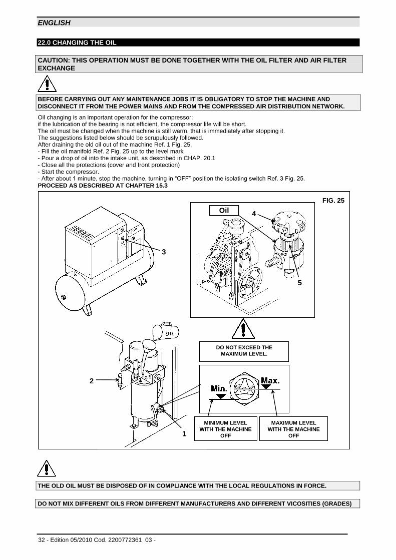
22.0 CHANGING THE OIL
CAUTION: THIS OPERATION MUST BE DONE TOGETHER WITH THE OIL FILTER AND AIR FILTER
EXCHANGE
BEFORE CARRYING OUT ANY MAINTENANCE JOBS IT IS OBLIGATORY TO STOP THE MACHINE AND
DISCONNECT IT FROM THE POWER MAINS AND FROM THE COMPRESSED AIR DISTRIBUTION NETWORK.
Oil changing is an important operation for the compressor: if the lubrication of the bearing is not efficient, the compressor life will be short. The oil must be changed when the machine is still warm, that is immediately after stopping it. The suggestions listed below should be scrupulously followed. After draining the old oil out of the machine Ref. 1 Fig. 25. - Fill the oil manifold Ref. 2 Fig. 25 up to the level mark - Pour a drop of oil into the intake unit, as described in CHAP. 20.1 - Close all the protections (cover and front protection) - Start the compressor. - After about 1 minute, stop the machine, turning in “OFF” position the isolating switch Ref. 3 Fig. 25.
PROCEED AS DESCRIBED AT CHAPTER 15.3
THE OLD OIL MUST BE DISPOSED OF IN COMPLIANCE WITH THE LOCAL REGULATIONS IN FORCE.
DO NOT MIX DIFFERENT OILS FROM DIFFERENT MANUFACTURERS AND DIFFERENT VICOSITIES (GRADES)
FIG. 25
DO NOT EXCEED THE
MAXIMUM LEVEL.
MAXIMUM LEVEL
WITH THE MACHINE
OFF
MINIMUM LEVEL
WITH THE MACHINE
OFF
1
5
4 Oil
3
2
ENGLISH
Cod. 2200772361 03 - Edition 05/2010 - 33
NOTE ON LUBRICANTS When delivered the machine is filled with oil. In normal conditions of use, these lubricants have proved to be able to withstand use for as many as 4.000 hours. However, due to the external polluting agents that get into the compressor with the air that it takes in, it is advisable to change the oil at more frequent intervals, as indicated on the routine maintenance chart. If the compressor is being used at high temperatures (continuous operation above 90 °C / 194° F) or in particularly severe conditions, we advise changing the oil at shorter intervals than those recommended in the maintenance chart.
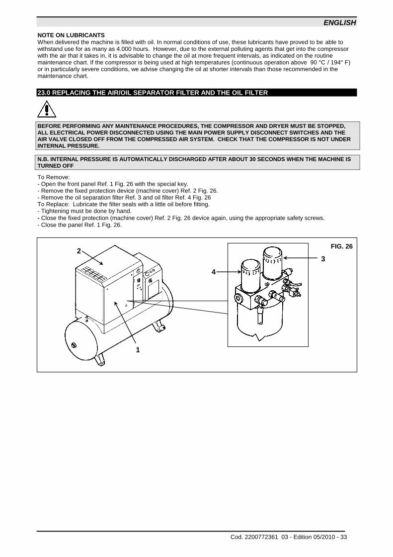
23.0 REPLACING THE AIR/OIL SEPARATOR FILTER AND THE OIL FILTER BEFORE PERFORMING ANY MAINTENANCE PROCEDURES, THE COMPRESSOR AND DRYER MUST BE STOPPED, ALL ELECTRICAL POWER DISCONNECTED USING THE MAIN POWER SUPPLY DISCONNECT SWITCHES AND THE AIR VALVE CLOSED OFF FROM THE COMPRESSED AIR SYSTEM. CHECK THAT THE COMPRESSOR IS NOT UNDER INTERNAL PRESSURE.
N.B. INTERNAL PRESSURE IS AUTOMATICALLY DISCHARGED AFTER ABOUT 30 SECONDS WHEN THE MACHINE IS TURNED OFF
To Remove: - Open the front panel Ref. 1 Fig. 26 with the special key. - Remove the fixed protection device (machine cover) Ref. 2 Fig. 26. - Remove the oil separation filter Ref. 3 and oil filter Ref. 4 Fig. 26 To Replace: Lubricate the filter seals with a little oil before fitting. - Tightening must be done by hand.
- Close the fixed protection (machine cover) Ref. 2 Fig. 26 device again, using the appropriate safety screws. - Close the panel Ref. 1 Fig. 26.
FIG. 26
4
3
2
1
ENGLISH
34 - Edition 05/2010 Cod. 2200772361 03 -
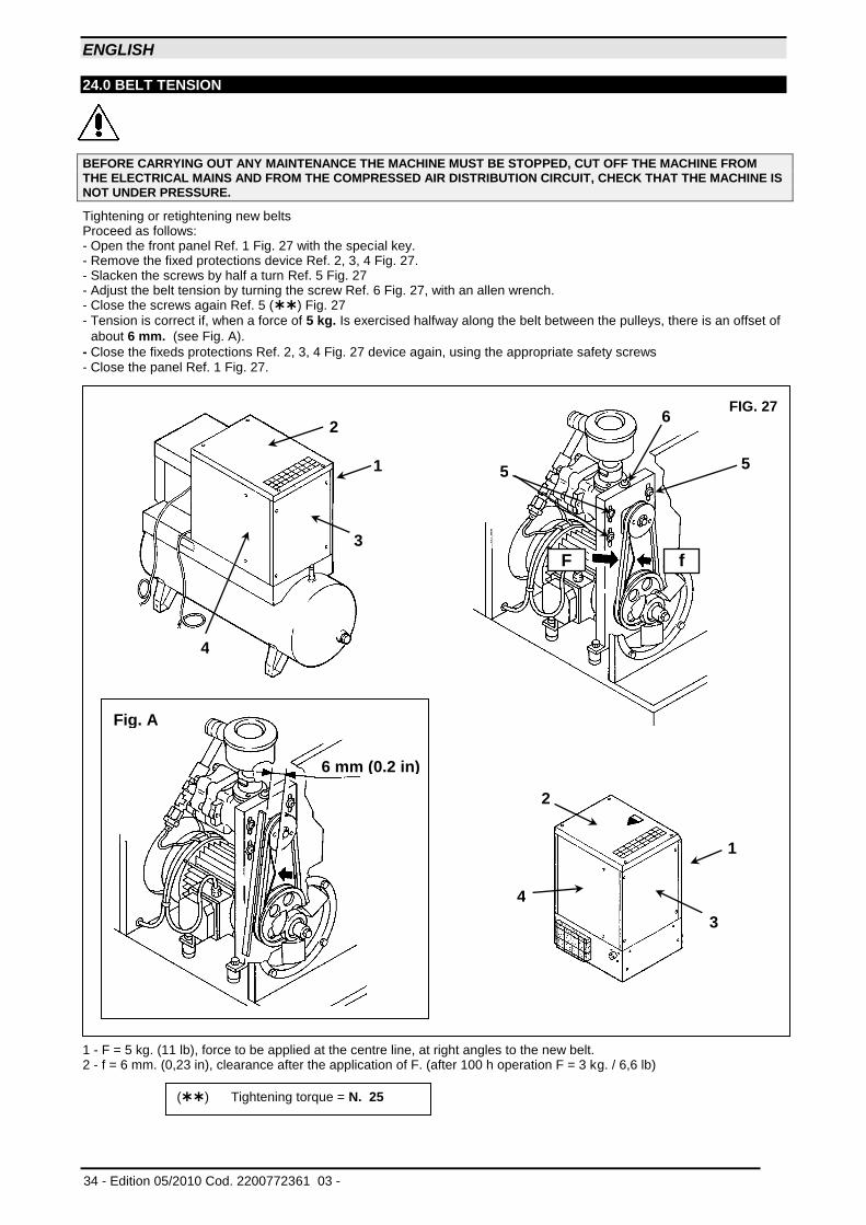
24.0 BELT TENSION
BEFORE CARRYING OUT ANY MAINTENANCE THE MACHINE MUST BE STOPPED, CUT OFF THE MACHINE FROM THE ELECTRICAL MAINS AND FROM THE COMPRESSED AIR DISTRIBUTION CIRCUIT, CHECK THAT THE MACHINE IS NOT UNDER PRESSURE.
Tightening or retightening new belts Proceed as follows: - Open the front panel Ref. 1 Fig. 27 with the special key. - Remove the fixed protections device Ref. 2, 3, 4 Fig. 27. - Slacken the screws by half a turn Ref. 5 Fig. 27 - Adjust the belt tension by turning the screw Ref. 6 Fig. 27, with an allen wrench. - Close the screws again Ref. 5 () Fig. 27
- Tension is correct if, when a force of 5 kg. Is exercised halfway along the belt between the pulleys, there is an offset of
about 6 mm. (see Fig. A).
- Close the fixeds protections Ref. 2, 3, 4 Fig. 27 device again, using the appropriate safety screws - Close the panel Ref. 1 Fig. 27.
1 - F = 5 kg. (11 lb), force to be applied at the centre line, at right angles to the new belt. 2 - f = 6 mm. (0,23 in), clearance after the application of F. (after 100 h operation F = 3 kg. / 6,6 lb)
() Tightening torque = N. 25
FIG. 27
5 5
6
6 mm (0.2 in)
Fig. A
f F
2
1
3
4
3
1
2
4
ENGLISH
Cod. 2200772361 03 - Edition 05/2010 - 35
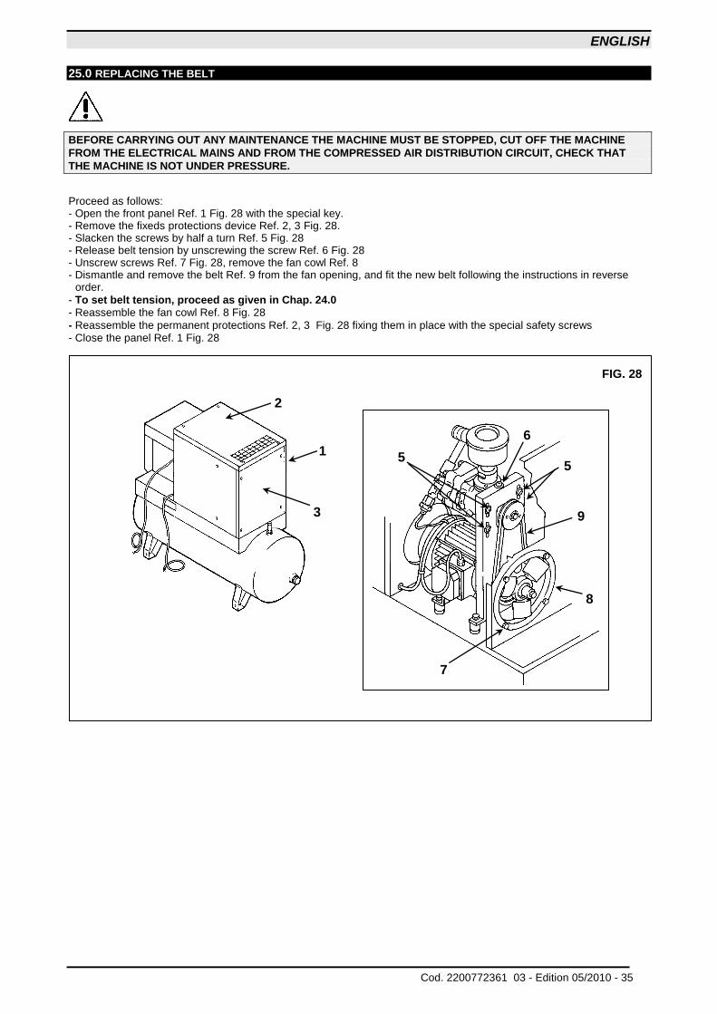
25.0 REPLACING THE BELT
BEFORE CARRYING OUT ANY MAINTENANCE THE MACHINE MUST BE STOPPED, CUT OFF THE MACHINE
FROM THE ELECTRICAL MAINS AND FROM THE COMPRESSED AIR DISTRIBUTION CIRCUIT, CHECK THAT
THE MACHINE IS NOT UNDER PRESSURE.
Proceed as follows: - Open the front panel Ref. 1 Fig. 28 with the special key. - Remove the fixeds protections device Ref. 2, 3 Fig. 28. - Slacken the screws by half a turn Ref. 5 Fig. 28 - Release belt tension by unscrewing the screw Ref. 6 Fig. 28 - Unscrew screws Ref. 7 Fig. 28, remove the fan cowl Ref. 8 - Dismantle and remove the belt Ref. 9 from the fan opening, and fit the new belt following the instructions in reverse
order.
- To set belt tension, proceed as given in Chap. 24.0 - Reassemble the fan cowl Ref. 8 Fig. 28
- Reassemble the permanent protections Ref. 2, 3 Fig. 28 fixing them in place with the special safety screws - Close the panel Ref. 1 Fig. 28
FIG. 28
6
5
9
8
7
5
2
1
3
ENGLISH
36 - Edition 05/2010 Cod. 2200772361 03 -
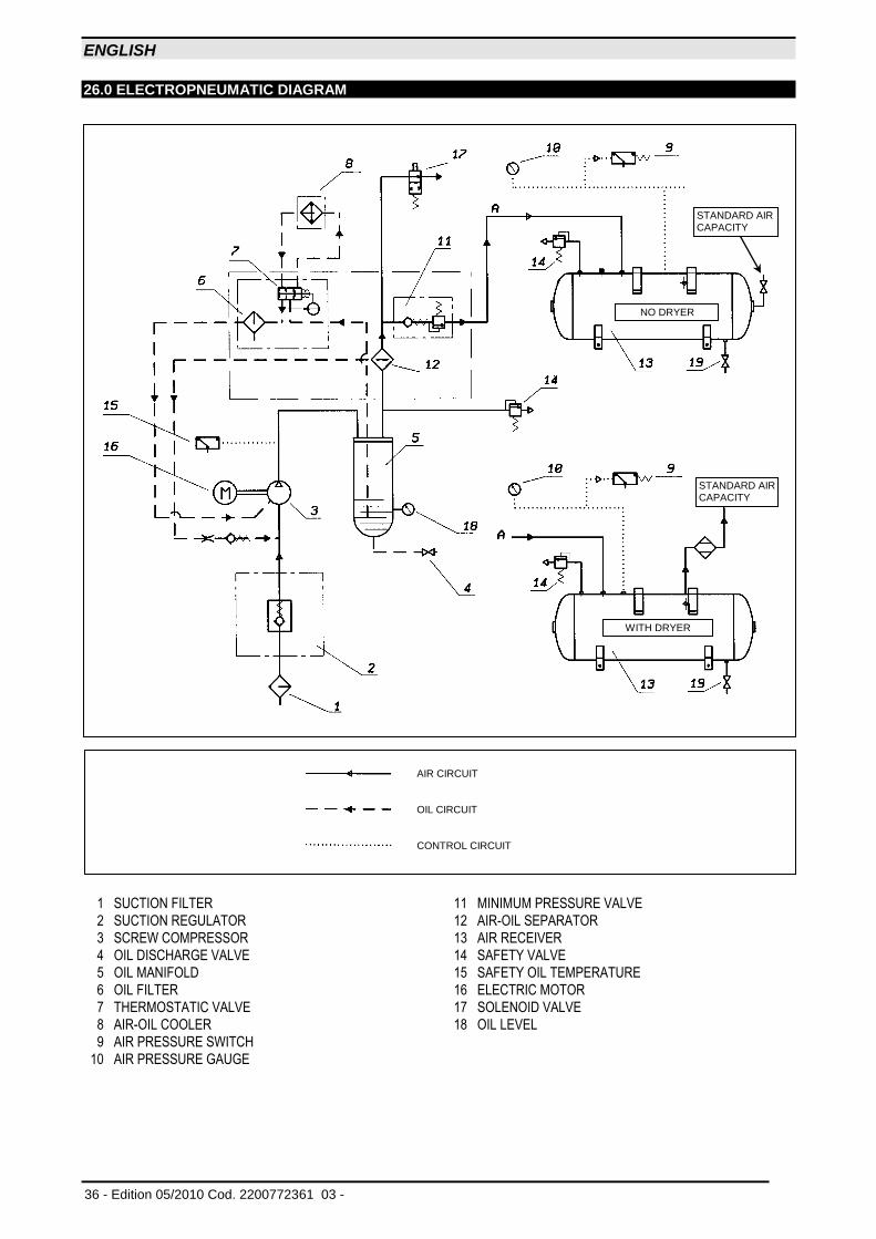
26.0 ELECTROPNEUMATIC DIAGRAM
1 SUCTION FILTER 11 MINIMUM PRESSURE VALVE
2 SUCTION REGULATOR 12 AIR-OIL SEPARATOR
3 SCREW COMPRESSOR 13 AIR RECEIVER
4 OIL DISCHARGE VALVE 14 SAFETY VALVE
5 OIL MANIFOLD 15 SAFETY OIL TEMPERATURE
6 OIL FILTER 16 ELECTRIC MOTOR
7 THERMOSTATIC VALVE 17 SOLENOID VALVE
8 AIR-OIL COOLER 18 OIL LEVEL
9 AIR PRESSURE SWITCH
10 AIR PRESSURE GAUGE
AIR CIRCUIT OIL CIRCUIT CONTROL CIRCUIT
NO DRYER
WITH DRYER
STANDARD AIR CAPACITY
STANDARD AIR CAPACITY
ENGLISH
Cod. 2200772361 03 - Edition 05/2010 - 37
27.0 PRESSURE SWITCH ADJUSTMENT
Note: Adjustments can only be made when the pressure switch is pressurized. The compressor uses a Condor MDR1/11 pressure switch to control the starting and stopping of the compressor. The stopping pressure is adjusted by rotating the adjustment screw clockwise to raise the pressure set point and counter-clockwise to lower the set point. The adjustment screw is accessible by removing the pressure switch cover.
The pressure differential between stopping and starting is a fixed setting at 2 bar (approx. 30 psi)
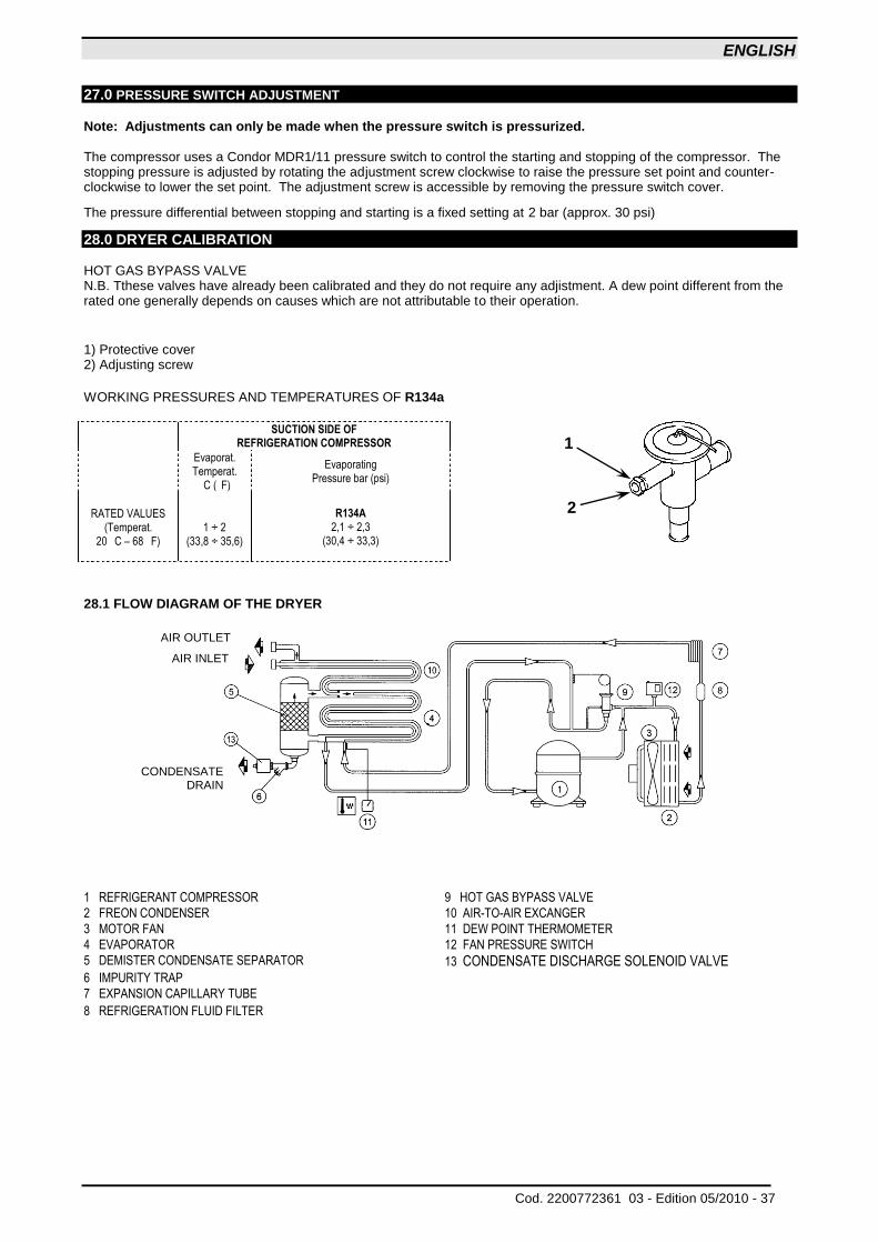
28.0 DRYER CALIBRATION HOT GAS BYPASS VALVE N.B. Tthese valves have already been calibrated and they do not require any adjistment. A dew point different from the rated one generally depends on causes which are not attributable to their operation.
1) Protective cover 2) Adjusting screw WORKING PRESSURES AND TEMPERATURES OF R134a
SUCTION SIDE OF
REFRIGERATION COMPRESSOR
Evaporat. Temperat.
C ( F)
Evaporating Pressure bar (psi)
RATED VALUES
(Temperat. 20 C – 68 F)
1 ÷ 2 (33,8 ÷ 35,6)
R134A
2,1 ÷ 2,3 (30,4 ÷ 33,3)
28.1 FLOW DIAGRAM OF THE DRYER
1 REFRIGERANT COMPRESSOR 9 HOT GAS BYPASS VALVE
2 FREON CONDENSER 10 AIR-TO-AIR EXCANGER
3 MOTOR FAN 11 DEW POINT THERMOMETER
4 EVAPORATOR 12 FAN PRESSURE SWITCH
5 DEMISTER CONDENSATE SEPARATOR 13 CONDENSATE DISCHARGE SOLENOID VALVE
6 IMPURITY TRAP
7 EXPANSION CAPILLARY TUBE 8 REFRIGERATION FLUID FILTER
2
1
AIR INLET
AIR OUTLET
CONDENSATE DRAIN
ENGLISH
38 - Edition 05/2010 Cod. 2200772361 03 -
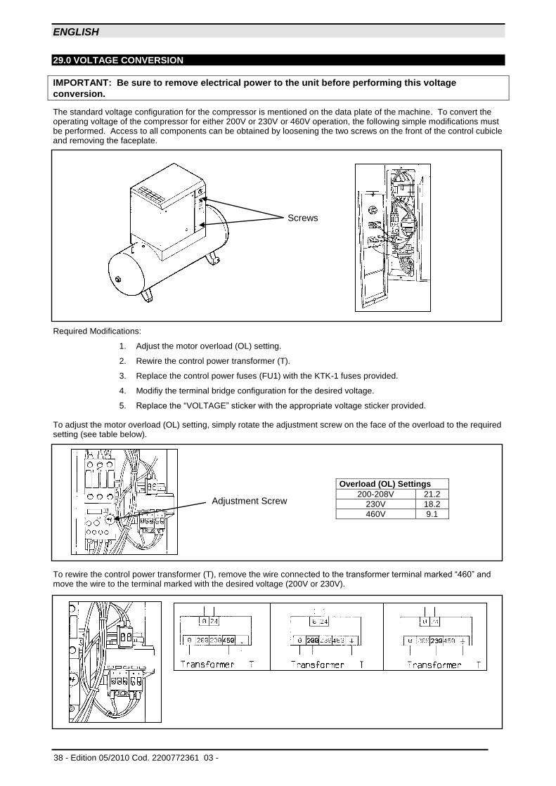
29.0 VOLTAGE CONVERSION
IMPORTANT: Be sure to remove electrical power to the unit before performing this voltage
conversion.
The standard voltage configuration for the compressor is mentioned on the data plate of the machine. To convert the operating voltage of the compressor for either 200V or 230V or 460V operation, the following simple modifications must be performed. Access to all components can be obtained by loosening the two screws on the front of the control cubicle and removing the faceplate. Required Modifications:
1. Adjust the motor overload (OL) setting.
2. Rewire the control power transformer (T).
3. Replace the control power fuses (FU1) with the KTK-1 fuses provided.
4. Modifiy the terminal bridge configuration for the desired voltage.
5. Replace the “VOLTAGE” sticker with the appropriate voltage sticker provided. To adjust the motor overload (OL) setting, simply rotate the adjustment screw on the face of the overload to the required setting (see table below).
To rewire the control power transformer (T), remove the wire connected to the transformer terminal marked “460” and move the wire to the terminal marked with the desired voltage (200V or 230V).
Adjustment Screw
Overload (OL) Settings
200-208V 21.2
230V 18.2
460V 9.1
Screws
ENGLISH
Cod. 2200772361 03 - Edition 05/2010 - 39
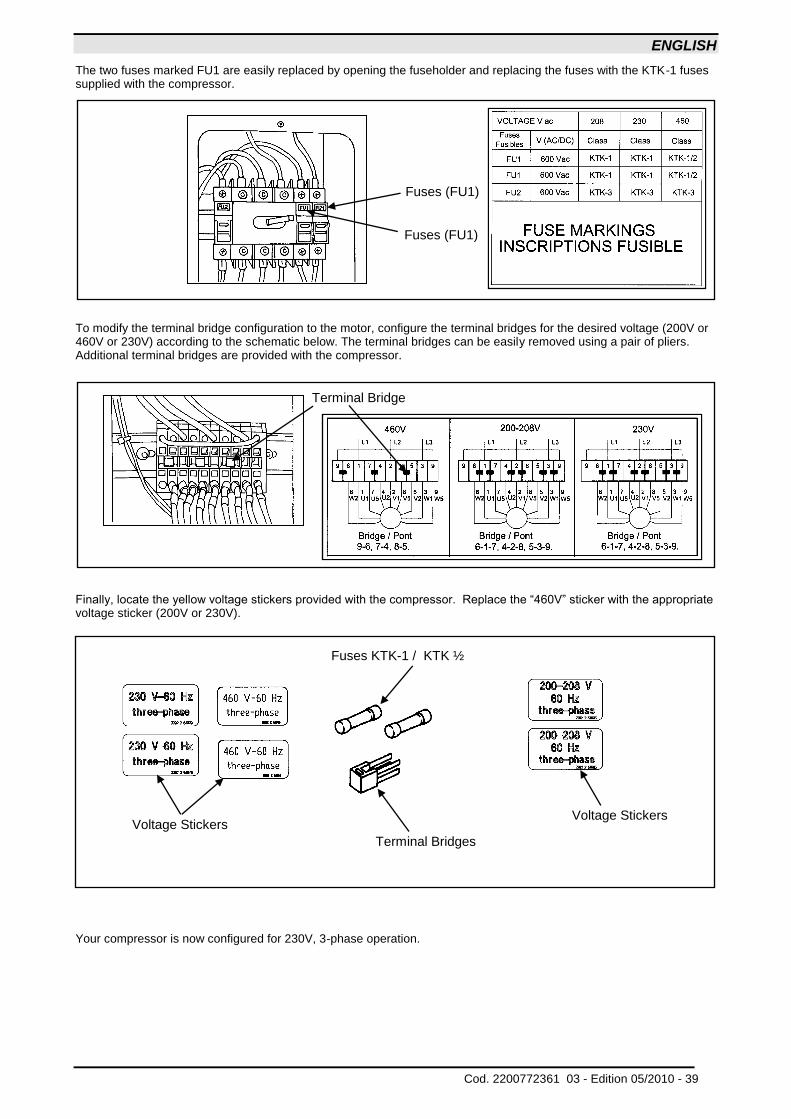
The two fuses marked FU1 are easily replaced by opening the fuseholder and replacing the fuses with the KTK-1 fuses supplied with the compressor.
To modify the terminal bridge configuration to the motor, configure the terminal bridges for the desired voltage (200V or 460V or 230V) according to the schematic below. The terminal bridges can be easily removed using a pair of pliers. Additional terminal bridges are provided with the compressor. Finally, locate the yellow voltage stickers provided with the compressor. Replace the “460V” sticker with the appropriate voltage sticker (200V or 230V).
Your compressor is now configured for 230V, 3-phase operation.
Fuses (FU1)
Fuses (FU1)
Terminal Bridge
Voltage Stickers
Terminal Bridges
Fuses KTK-1 / KTK ½
Voltage Stickers
ENGLISH
40 - Edition 05/2010 Cod. 2200772361 03 -
NOTE