Embed Size (px)
Citation preview
Rotary indexing tables DHTG
Subject to change – 2008/042 � Internet: www.festo.com/catalogue/...
Rotary indexing tables DHTGKey features
At a glance
• Robust mechanics
• Simple planning
and commissioning
• Number of stations:
2, 3, 4, 6, 8, 12, 24
• Smooth motion sequence, almost
sinusoidal acceleration behaviour
• Control options:
– Anti-clockwise
– Clockwise
– Reciprocating motion
• Integrated functions:
– Overload protection
– Sensor function
– Cushioning adjustment
– Speed setting
– Changing the direction
of rotation
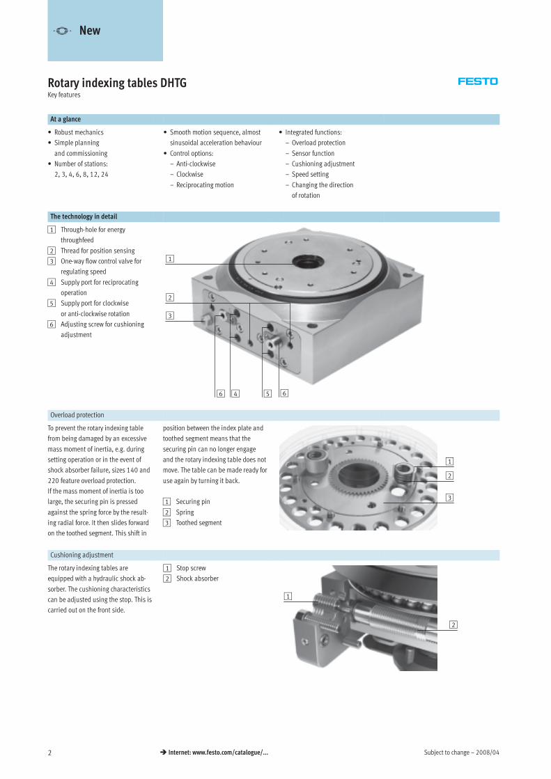
The technology in detail
1 Through-hole for energy
throughfeed
2 Thread for position sensing
3 One-way flow control valve for
regulating speed
4 Supply port for reciprocating
operation
5 Supply port for clockwise
or anti-clockwise rotation
6 Adjusting screw for cushioning
adjustment
1
3
2
4 56 6
Overload protection
To prevent the rotary indexing table
from being damaged by an excessive
mass moment of inertia, e.g. during
setting operation or in the event of
shock absorber failure, sizes 140 and
220 feature overload protection.
If the mass moment of inertia is too
large, the securing pin is pressed
against the spring force by the result-
ing radial force. It then slides forward
on the toothed segment. This shift in
position between the index plate and
toothed segment means that the
securing pin can no longer engage
and the rotary indexing table does not
move. The table can be made ready for
use again by turning it back.
1 Securing pin
2 Spring
3 Toothed segment
1
2
3
Cushioning adjustment
The rotary indexing tables are
equipped with a hydraulic shock ab-
sorber. The cushioning characteristics
can be adjusted using the stop. This is
carried out on the front side.
1 Stop screw
2 Shock absorber
2
1
-V- New
2008/04 – Subject to change 3� Internet: www.festo.com/catalogue/...
Rotary indexing tables DHTGKey features
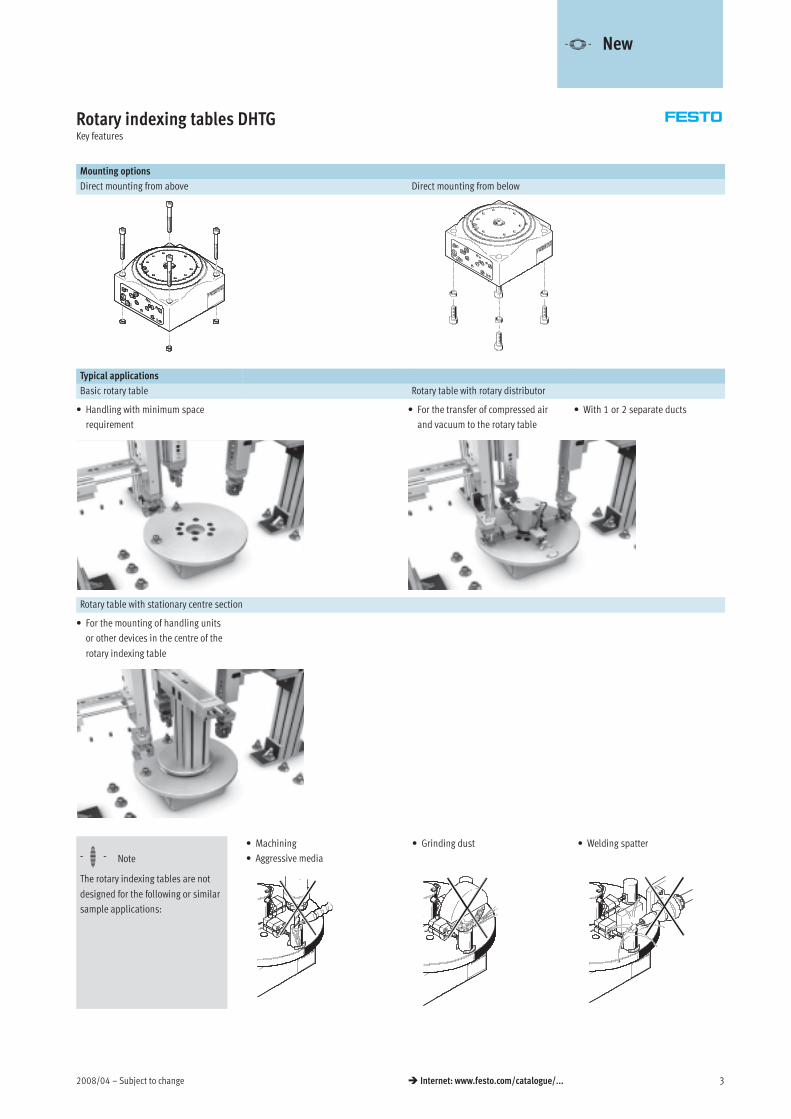
Mounting options
Direct mounting from above Direct mounting from below
Typical applications
Basic rotary table Rotary table with rotary distributor
• Handling with minimum space
requirement
• For the transfer of compressed air
and vacuum to the rotary table
• With 1 or 2 separate ducts
Rotary table with stationary centre section
• For the mounting of handling units
or other devices in the centre of the
rotary indexing table
-H- Note
The rotary indexing tables are not
designed for the following or similar
sample applications:
• Welding spatter• Grinding dust• Machining
• Aggressive media
-V- New
Products 2008 – Subject to change – 2007/101 / 7.2-4
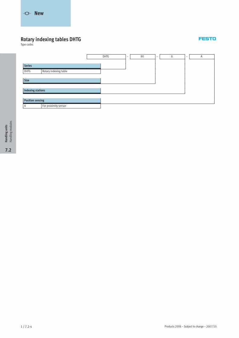
Rotary indexing tables DHTGType codes
DHTG – 90 – 8 – A
Series
DHTG Rotary indexing table
Size
Indexing stations
Position sensing
A For proximity sensor
Handlingunits
Handlingmodules
7.2
-V- New
2008/05 – Subject to change 5� Internet: www.festo.com/catalogue/...
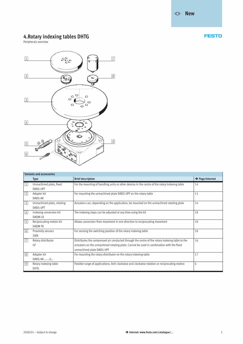
4.Rotary indexing tables DHTGPeripherals overview
1 7
2
3
4
5
6
8
9
Variants and accessories
Type Brief description � Page/Internet
1 Unmachined plate, fixed
DADG-UPF
For the mounting of handling units or other devices in the centre of the rotary indexing table 14
2 Adapter kit
DADG-AK
For mounting the unmachined plate DADG-UPF on the rotary table 15
3 Unmachined plate, rotating
DADG-UPT
Actuators can, depending on the application, be mounted on the unmachined rotating plate 14
4 Indexing conversion kit
DADM-CK
The indexing steps can be adjusted at any time using the kit 18
5 Reciprocating motion kit
DADM-TK
Allows conversion from movement in one direction to reciprocating movement 18
6 Proximity sensors
SIEN
For sensing the switching position of the rotary indexing table 18
7 Rotary distributor
GF
Distributes the compressed air conducted through the centre of the rotary indexing table to the
actuators on the unmachined rotating plate. Cannot be used in combination with the fixed
unmachined plate DADG-UPF
16
8 Adapter kit
DADG-AK-…-…G…
For mounting the rotary distributor on the rotary indexing table 17
9 Rotary indexing table
DHTG
Flexible range of applications: Anti-clockwise and clockwise rotation or reciprocating motion 6
-V- New
Subject to change – 2008/056 � Internet: www.festo.com/catalogue/...
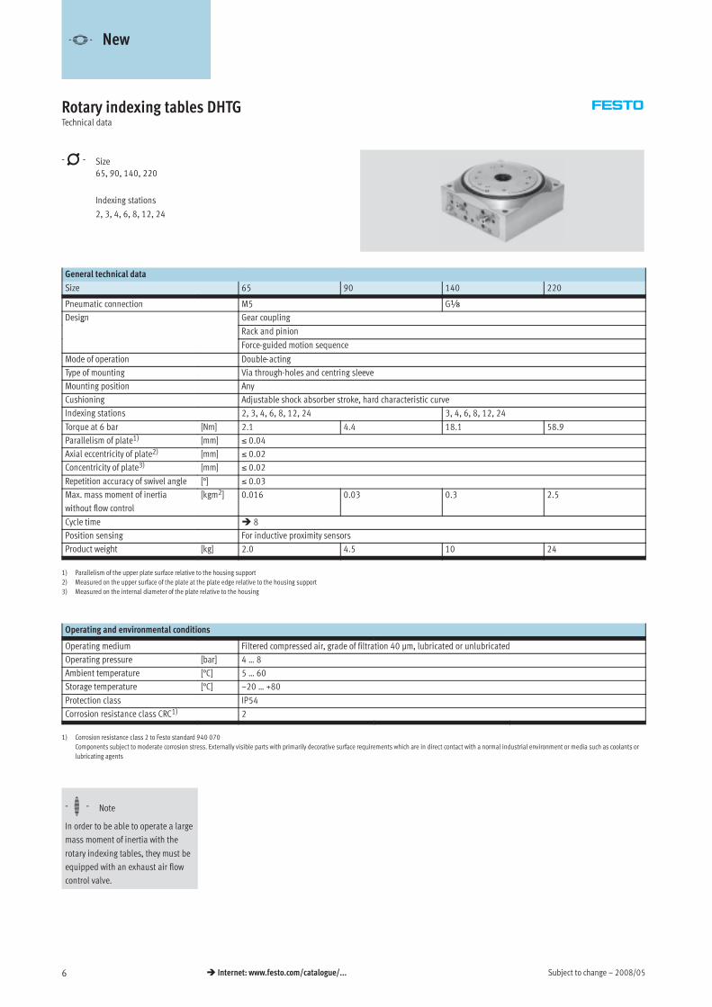
Rotary indexing tables DHTGTechnical data
-N- Size
65, 90, 140, 220
Indexing stations
2, 3, 4, 6, 8, 12, 24
General technical data
Size 65 90 140 220
Pneumatic connection M5 Gx
Design Gear couplingg
Rack and pinion
Force-guided motion sequence
Mode of operation Double-acting
Type of mounting Via through-holes and centring sleeve
Mounting position Any
Cushioning Adjustable shock absorber stroke, hard characteristic curve
Indexing stations 2, 3, 4, 6, 8, 12, 24 3, 4, 6, 8, 12, 24
Torque at 6 bar [Nm] 2.1 4.4 18.1 58.9
Parallelism of plate1) [mm] ≤ 0.04
Axial eccentricity of plate2) [mm] ≤ 0.02
Concentricity of plate3) [mm] ≤ 0.02
Repetition accuracy of swivel angle [°] ≤ 0.03
Max. mass moment of inertia
without flow control
[kgm2] 0.016 0.03 0.3 2.5
Cycle time � 8
Position sensing For inductive proximity sensors
Product weight [kg] 2.0 4.5 10 24
1) Parallelism of the upper plate surface relative to the housing support
2) Measured on the upper surface of the plate at the plate edge relative to the housing support
3) Measured on the internal diameter of the plate relative to the housing
Operating and environmental conditions
Operating medium Filtered compressed air, grade of filtration 40 µm, lubricated or unlubricated
Operating pressure [bar] 4 … 8
Ambient temperature [°C] 5 … 60
Storage temperature [°C] –20 … +80
Protection class IP54
Corrosion resistance class CRC1) 2
1) Corrosion resistance class 2 to Festo standard 940 070
Components subject to moderate corrosion stress. Externally visible parts with primarily decorative surface requirements which are in direct contact with a normal industrial environment or media such as coolants or
lubricating agents
-H- Note
In order to be able to operate a large
mass moment of inertia with the
rotary indexing tables, they must be
equipped with an exhaust air flow
control valve.
-V- New
2008/05 – Subject to change 7� Internet: www.festo.com/catalogue/...
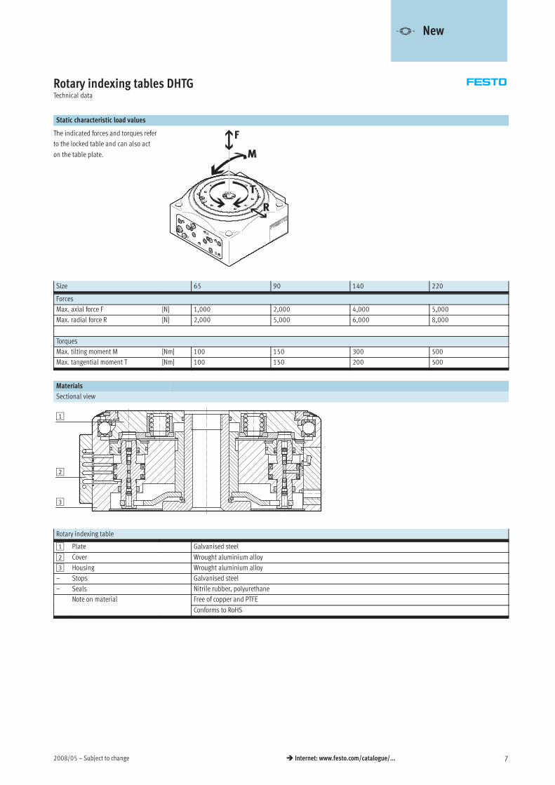
Rotary indexing tables DHTGTechnical data
Static characteristic load values
The indicated forces and torques refer
to the locked table and can also act
on the table plate.
Size 65 90 140 220
Forces
Max. axial force F [N] 1,000 2,000 4,000 5,000
Max. radial force R [N] 2,000 5,000 6,000 8,000
Torques
Max. tilting moment M [Nm] 100 150 300 500
Max. tangential moment T [Nm] 100 150 200 500
Materials
Sectional view
3
2
1
Rotary indexing table
1 Plate Galvanised steel
2 Cover Wrought aluminium alloy
3 Housing Wrought aluminium alloy
– Stops Galvanised steel
– Seals Nitrile rubber, polyurethane
Note on material Free of copper and PTFE
Conforms to RoHS
-V- New
Subject to change – 2008/058 � Internet: www.festo.com/catalogue/...
Rotary indexing tables DHTGTechnical data
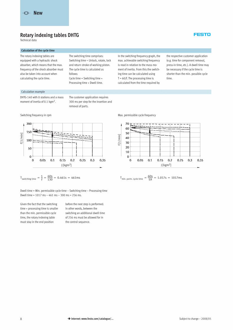
Calculation of the cycle time
The rotary indexing tables are
equipped with a hydraulic shock
absorber, which means that the max.
frequency of the shock absorber must
also be taken into account when
calculating the cycle time.
The switching time comprises:
Switching time = Unlock, rotate, lock
and return stroke of working piston.
The cycle time is calculated as
follows:
Cycle time = Switching time +
Processing time + Dwell time.
In the switching frequency graph, the
max. achievable switching frequency
is read in relation to the mass mo-
ment of inertia. From this the switch-
ing time can be calculated using
T = 60/f. The processing time is
calculated from the time required by
the respective customer application
(e.g. time for component removal,
press-in time, etc.). A dwell time may
be necessary if the cycle time is
shorter than the min. possible cycle
time.
Calculation example
DHTG-140 with 8 stations and a mass
moment of inertia of 0.1 kgm2.
The customer application requires
300 ms per step for the insertion and
removal of parts.
Switching frequency in rpm Max. permissible cycle frequency
Tswitching time =1f=
60s130
= 0.461s = 461ms Tmin. perm. cycle time =60s59
= 1.017s = 1017ms
Dwell time = Min. permissible cycle time – Switching time – Processing time
Dwell time = 1017 ms – 461 ms – 300 ms = 256 ms.
Given the fact that the switching
time + processing time is smaller
than the min. permissible cycle
time, the rotary indexing table
must stay in the end position
before the next step is performed.
In other words, between the
switching an additional dwell time
of 256 ms must be allowed for in
the control sequence.
f[1/m
in]
J [kgm2] J [kgm2]
f[1/m
in]
-V- New
2008/05 – Subject to change 9� Internet: www.festo.com/catalogue/...
Rotary indexing tables DHTGTechnical data
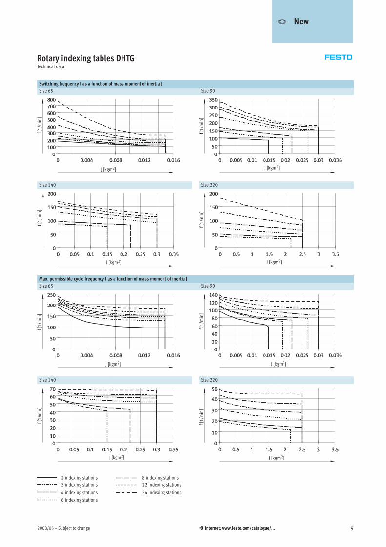
Switching frequency f as a function of mass moment of inertia J
Size 65 Size 90
f[1/m
in]
J [kgm2] J [kgm2]
f[1/m
in]
Size 140 Size 220
f[1/m
in]
J [kgm2]
f[1/m
in]
J [kgm2]
Max. permissible cycle frequency f as a function of mass moment of inertia J
Size 65 Size 90
f[1/m
in]
J [kgm2]
f[1/m
in]
J [kgm2]
Size 140 Size 220
2 indexing stations
3 indexing stations
4 indexing stations
6 indexing stations
8 indexing stations
12 indexing stations
24 indexing stations
J [kgm2]
f[1/m
in]
J [kgm2]
f[1/m
in]
-V- New
Subject to change – 2008/0510 � Internet: www.festo.com/catalogue/...
Rotary indexing tables DHTGTechnical data
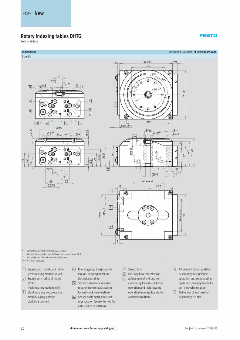
Dimensions Download CAD data� www.festo.com
Size 65
* Tolerance between the centring holes: ±0.02
Tolerance between the threaded holes and countersinks: ±0.2
** Max. projection of shock absorber adjustment
*** 0.1 +0.05 recessed
1 Supply port: unlock and rotate
(reciprocating motion: unlock)
2 Supply port: lock and return
stroke
(reciprocating motion: lock)
3 Blanking plug; (reciprocating
motion: supply port for
clockwise turning)
4 Blanking plug; (reciprocating
motion: supply port for anti-
clockwise turning)
5 Sensor turned for clockwise
rotation (sensor basic setting
for anti-clockwise rotation)
6 Sensor basic setting for clock-
wise rotation (sensor turned for
anti-clockwise rotation)
7 Sensor lock
8 One-way flow control valve
9 Adjustment of end position
cushioning for anti-clockwise
operation and reciprocating
operation (non-applicable for
clockwise rotation)
aJ Adjustment of end position
cushioning for clockwise
operation and reciprocating
operation (non-applicable for
anti-clockwise rotation)
aA Tightening of end position
cushioning 2.5 Nm
-V- New
2008/05 – Subject to change 11� Internet: www.festo.com/catalogue/...
Rotary indexing tables DHTGTechnical data
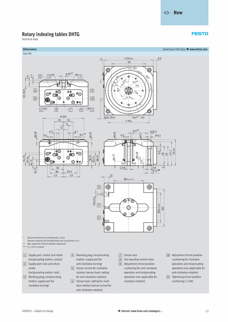
Dimensions Download CAD data� www.festo.com
Size 90
* Tolerance between the centring holes: ±0.02
Tolerance between the threaded holes and countersinks: ±0.2
** Max. projection of shock absorber adjustment
*** 0.1 +0.05 recessed
1 Supply port: unlock and rotate
(reciprocating motion: unlock)
2 Supply port: lock and return
stroke
(reciprocating motion: lock)
3 Blanking plug; (reciprocating
motion: supply port for
clockwise turning)
4 Blanking plug; (reciprocating
motion: supply port for
anti-clockwise turning)
5 Sensor turned for clockwise
rotation (sensor basic setting
for anti-clockwise rotation)
6 Sensor basic setting for clock-
wise rotation (sensor turned for
anti-clockwise rotation)
7 Sensor lock
8 One-way flow control valve
9 Adjustment of end position
cushioning for anti-clockwise
operation and reciprocating
operation (non-applicable for
clockwise rotation)
aJ Adjustment of end position
cushioning for clockwise
operation and reciprocating
operation (non-applicable for
anti-clockwise rotation)
aA Tightening of end position
cushioning 2.5 Nm
-V- New
Subject to change – 2008/0512 � Internet: www.festo.com/catalogue/...
Rotary indexing tables DHTGTechnical data
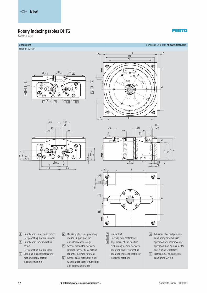
Dimensions Download CAD data� www.festo.com
Sizes 140, 220
1 Supply port: unlock and rotate
(reciprocating motion: unlock)
2 Supply port: lock and return
stroke
(reciprocating motion: lock)
3 Blanking plug; (reciprocating
motion: supply port for
clockwise turning)
4 Blanking plug; (reciprocating
motion: supply port for
anti-clockwise turning)
5 Sensor turned for clockwise
rotation (sensor basic setting
for anti-clockwise rotation)
6 Sensor basic setting for clock-
wise rotation (sensor turned for
anti-clockwise rotation)
7 Sensor lock
8 One-way flow control valve
9 Adjustment of end position
cushioning for anti-clockwise
operation and reciprocating
operation (non-applicable for
clockwise rotation)
aJ Adjustment of end position
cushioning for clockwise
operation and reciprocating
operation (non-applicable for
anti-clockwise rotation)
aA Tightening of end position
cushioning 2.5 Nm
-V- New
2008/05 – Subject to change 13� Internet: www.festo.com/catalogue/...
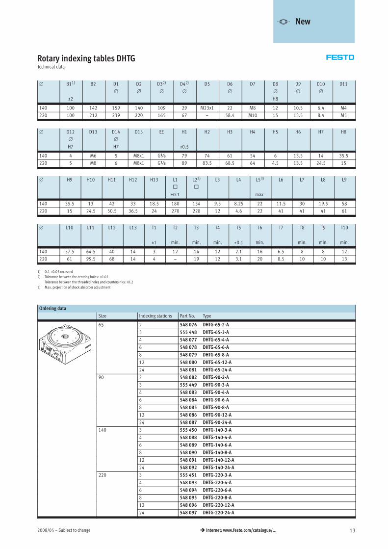
Rotary indexing tables DHTGTechnical data
∅ B11)
±2
B2 D1
∅
D2
∅
D32)
∅
D42)
∅
D5 D6
∅
D7 D8
∅
H8
D9
∅
D10
∅
D11
140 100 142 159 140 109 29 M23x1 22 M8 12 10.5 6.4 M4
220 100 212 239 220 165 67 z 58.4 M10 15 13.5 8.4 M5
∅ D12
∅
H7
D13 D14
∅
H7
D15 EE H1
±0.5
H2 H3 H4 H5 H6 H7 H8
140 4 M6 5 M8x1 Gx 79 74 61 54 6 13.5 14 35.5
220 5 M8 6 M8x1 Gx 89 83.5 68.5 64 4.5 13.5 24.5 15
∅ H9 H10 H11 H12 H13 L1
™
±0.1
L22)
™
L3 L4 L53)
max.
L6 L7 L8 L9
140 35.5 13 42 33 18.5 180 154 9.5 8.25 22 11.5 30 19.5 58
220 15 24.5 50.5 36.5 24 270 228 12 4.6 22 41 41 41 61
∅ L10 L11 L12 L13 T1
±1
T2
min.
T3
min.
T4
min.
T5
+0.1
T6
min.
T7 T8
min.
T9
min.
T10
min.
140 57.5 64.5 40 14 3 12 14 12 2.1 16 6.5 8 8 12
220 61 99.5 68 14 4 z 19 12 3.1 20 8.5 10 10 13
1) 0.1 +0.05 recessed
2) Tolerance between the centring holes: ±0.02
Tolerance between the threaded holes and countersinks: ±0.2
3) Max. projection of shock absorber adjustment
Ordering data
Size Indexing stations Part No. Type
65 2 548 076 DHTG-65-2-A5
3 555 448 DHTG-65-3-A
4 548 077 DHTG-65-4-A
6 548 078 DHTG-65-6-A
8 548 079 DHTG-65-8-A
12 548 080 DHTG-65-12-A
24 548 081 DHTG-65-24-A
90 2 548 082 DHTG-90-2-A9
3 555 449 DHTG-90-3-A
4 548 083 DHTG-90-4-A
6 548 084 DHTG-90-6-A
8 548 085 DHTG-90-8-A
12 548 086 DHTG-90-12-A
24 548 087 DHTG-90-24-A
140 3 555 450 DHTG-140-3-A
4 548 088 DHTG-140-4-A
6 548 089 DHTG-140-6-A
8 548 090 DHTG-140-8-A
12 548 091 DHTG-140-12-A
24 548 092 DHTG-140-24-A
220 3 555 451 DHTG-220-3-A
4 548 093 DHTG-220-4-A
6 548 094 DHTG-220-6-A
8 548 095 DHTG-220-8-A
12 548 096 DHTG-220-12-A
24 548 097 DHTG-220-24-A
-V- New
Subject to change – 2008/0514 � Internet: www.festo.com/catalogue/...
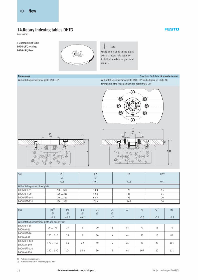
14.Rotary indexing tables DHTGAccessories
15.Unmachined table
DADG-UPT, rotating
DADG-UPF, fixed
-H- Note
You can order unmachined plates
with a standard hole pattern or
individual interface via your local
contact.
Dimensions Download CAD data� www.festo.com
With rotating unmachined plate DADG-UPT With rotating unmachined plate DADG-UPT and adapter kit DADG-AK
for mounting the fixed unmachined plate DADG-UPF
Size D11)
∅
±0.3
D2
∅
+0.1
H1
±0.5
H22)
±0.1
With rotating unmachined plate
DADG-UPT-65 90 … 170 30.3 70 15
DADG-UPT-90 120 … 210 40.4 85 15
DADG-UPT-140 170 … 350 65.3 99 20
DADG-UPT-220 250 … 550 105.4 103 20
Size D11)
∅
±0.3
D3
∅
+0.2
D4
∅
+0.2
D5
∅
D6
∅
H7
D7 H1
±0.5
H22)
±0.1
H3
±0.5
With rotating unmachined plate and adapter kit
DADG-UPT-65
DADG-AK-6590 … 170 29 5 20 4 M4 70 15 72
DADG-UPT-90
DADG-AK-90120 … 210 39 9 30 4 M4 85 15 87
DADG-UPT-140
DADG-AK-140170 … 350 64 22 50 5 M6 99 20 101
DADG-UPT-220
DADG-AK-220250 … 550 104 58.4 90 6 M8 109 20 111
1) Plate diameter as required
2) Plate thickness can be reduced by up to 5 mm
-V- New
2008/05 – Subject to change 15� Internet: www.festo.com/catalogue/...
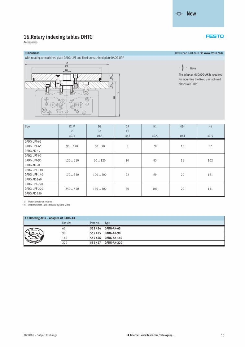
16.Rotary indexing tables DHTGAccessories
Dimensions Download CAD data� www.festo.com
With rotating unmachined plate DADG-UPT and fixed unmachined plate DADG-UPF
-H- Note
The adapter kit DADG-AK is required
for mounting the fixed unmachined
plate DADG-UPF.
Size D11)
∅
±0.3
D8
∅
±0.3
D9
∅
+0.2
H1
±0.5
H22)
±0.1
H4
±0.5
DADG-UPT-65
DADG-UPF-65
DADG-AK-65
90 … 170 50 … 90 5 70 15 87
DADG-UPT-90
DADG-UPF-90
DADG-AK-90
120 … 210 60 … 120 10 85 15 102
DADG-UPT-140
DADG-UPF-140
DADG-AK-140
170 … 350 100 … 200 22 99 20 121
DADG-UPT-220
DADG-UPF-220
DADG-AK-220
250 … 550 140 … 300 60 109 20 131
1) Plate diameter as required
2) Plate thickness can be reduced by up to 5 mm
17.Ordering data – Adapter kit DADG-AK
For size Part No. Type
65 555 424 DADG-AK-65
90 555 425 DADG-AK-90
140 555 426 DADG-AK-140
220 555 427 DADG-AK-220
-V- New
Subject to change – 2008/0516 � Internet: www.festo.com/catalogue/...
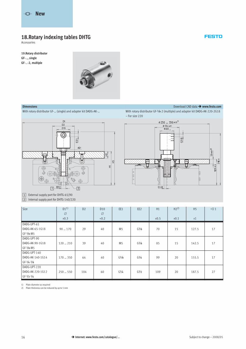
18.Rotary indexing tables DHTGAccessories
19.Rotary distributor
GF-…, single
GF-…-2, multiple
Dimensions Download CAD data� www.festo.com
With rotary distributor GF-… (single) and adapter kit DADG-AK-… With rotary distributor GF-x-2 (multiple) and adapter kit DADG-AK-220-2G18
– For size 220
1 External supply port for DHTG-65/90
2 Internal supply port for DHTG-140/220
Size D11)
∅
±0.3
D2 D10
∅
+0.2
EE1 EE2 H1
±0.5
H22)
±0.1
H5
±1
ß 1
DADG-UPT-65
DADG-AK-65-1G18
GF-x-M5
90 … 170 29 40 M5 Gx 70 15 127.5 17
DADG-UPT-90
DADG-AK-90-1G18
GF-x-M5
120 … 210 39 40 M5 Gx 85 15 142.5 17
DADG-UPT-140
DADG-AK-140-1G14
GF-¼-x
170 … 350 64 40 Gx G¼ 99 20 155.5 17
DADG-UPT-220
DADG-AK-220-1G12
GF-½-¼
250 … 550 104 60 G¼ G½ 109 20 187.5 27
1) Plate diameter as required
2) Plate thickness can be reduced by up to 5 mm
-V- New
2008/05 – Subject to change 17� Internet: www.festo.com/catalogue/...
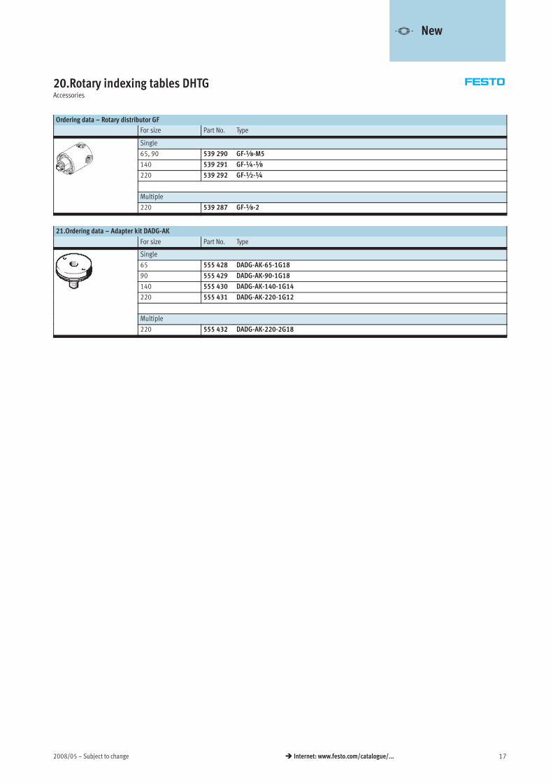
20.Rotary indexing tables DHTGAccessories
Ordering data – Rotary distributor GF
For size Part No. Type
Single
65, 90 539 290 GF-x-M5
140 539 291 GF-¼-x
220 539 292 GF-½-¼
Multiple
220 539 287 GF-x-2
21.Ordering data – Adapter kit DADG-AK
For size Part No. Type
Single
65 555 428 DADG-AK-65-1G18
90 555 429 DADG-AK-90-1G18
140 555 430 DADG-AK-140-1G14
220 555 431 DADG-AK-220-1G12
Multiple
220 555 432 DADG-AK-220-2G18
-V- New
Subject to change – 2008/0518 � Internet: www.festo.com/catalogue/...
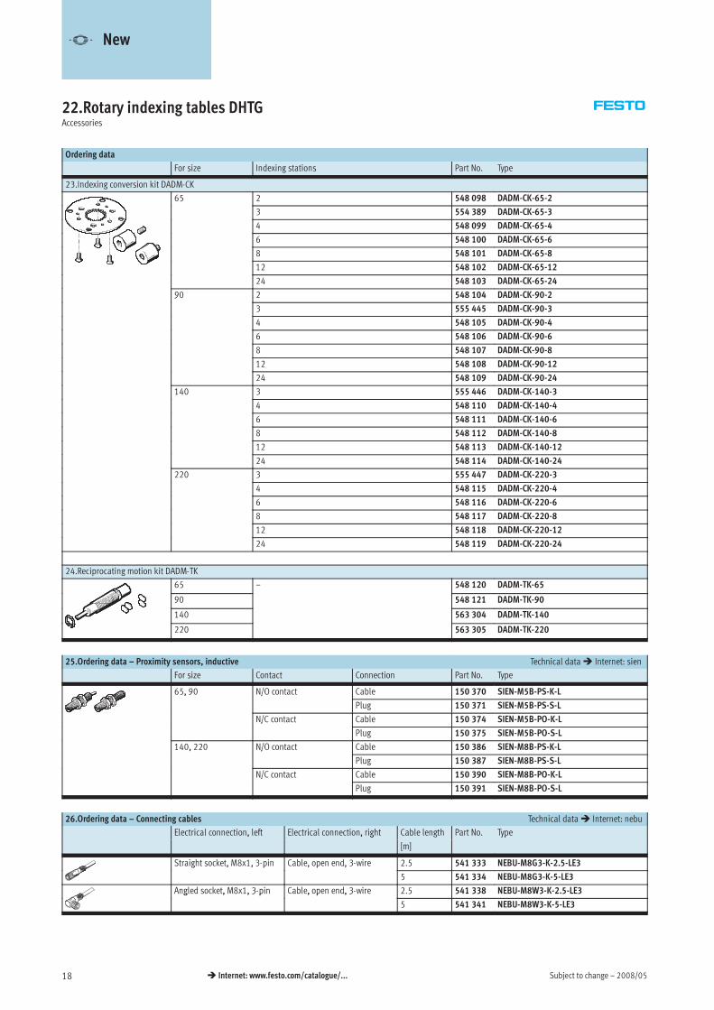
22.Rotary indexing tables DHTGAccessories
Ordering data
For size Indexing stations Part No. Type
23.Indexing conversion kit DADM-CK
65 2 548 098 DADM-CK-65-25
3 554 389 DADM-CK-65-3
4 548 099 DADM-CK-65-4
6 548 100 DADM-CK-65-6
8 548 101 DADM-CK-65-8
12 548 102 DADM-CK-65-12
24 548 103 DADM-CK-65-24
90 2 548 104 DADM-CK-90-29
3 555 445 DADM-CK-90-3
4 548 105 DADM-CK-90-4
6 548 106 DADM-CK-90-6
8 548 107 DADM-CK-90-8
12 548 108 DADM-CK-90-12
24 548 109 DADM-CK-90-24
140 3 555 446 DADM-CK-140-3
4 548 110 DADM-CK-140-4
6 548 111 DADM-CK-140-6
8 548 112 DADM-CK-140-8
12 548 113 DADM-CK-140-12
24 548 114 DADM-CK-140-24
220 3 555 447 DADM-CK-220-3
4 548 115 DADM-CK-220-4
6 548 116 DADM-CK-220-6
8 548 117 DADM-CK-220-8
12 548 118 DADM-CK-220-12
24 548 119 DADM-CK-220-24
24.Reciprocating motion kit DADM-TK
65 – 548 120 DADM-TK-65
90 548 121 DADM-TK-90
140 563 304 DADM-TK-140
220 563 305 DADM-TK-220
25.Ordering data – Proximity sensors, inductive Technical data� Internet: sien
For size Contact Connection Part No. Type
65, 90 N/O contact Cable 150 370 SIEN-M5B-PS-K-L5, 9 /
Plug 150 371 SIEN-M5B-PS-S-L
N/C contact Cable 150 374 SIEN-M5B-PO-K-L/
Plug 150 375 SIEN-M5B-PO-S-L
140, 220 N/O contact Cable 150 386 SIEN-M8B-PS-K-L, /
Plug 150 387 SIEN-M8B-PS-S-L
N/C contact Cable 150 390 SIEN-M8B-PO-K-L/
Plug 150 391 SIEN-M8B-PO-S-L
26.Ordering data – Connecting cables Technical data� Internet: nebu
Electrical connection, left Electrical connection, right Cable length Part No. Type, , g
[m]
yp
Straight socket, M8x1, 3-pin Cable, open end, 3-wire 2.5 541 333 NEBU-M8G3-K-2.5-LE3g , , 3 p , p , 3
5 541 334 NEBU-M8G3-K-5-LE3
Angled socket, M8x1, 3-pin Cable, open end, 3-wire 2.5 541 338 NEBU-M8W3-K-2.5-LE3g , , 3 p , p , 3
5 541 341 NEBU-M8W3-K-5-LE3
-V- New
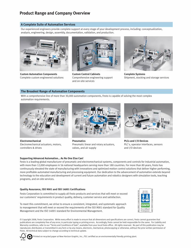
Product Range and Company Overview
The Broadest Range of Automation Components
With a comprehensive line of more than 30,000 automation components, Festo is capable of solving the most complex
automation requirements.
Supporting Advanced Automation… As No One Else Can!
Festo is a leading global manufacturer of pneumatic and electromechanical systems, components and controls for industrial automation,
with more than 12,000 employees in 56 national headquarters serving more than 180 countries. For more than 80 years, Festo has
continuously elevated the state of manufacturing with innovations and optimized motion control solutions that deliver higher performing,
more profitable automated manufacturing and processing equipment. Our dedication to the advancement of automation extends beyond
technology to the education and development of current and future automation and robotics designers with simulation tools, teaching
programs, and on-site services.
Quality Assurance, ISO 9001 and ISO 14001 Certifications
Festo Corporation is committed to supply all Festo products and services that will meet or exceed
our customers’ requirements in product quality, delivery, customer service and satisfaction.
To meet this commitment, we strive to ensure a consistent, integrated, and systematic approach
to management that will meet or exceed the requirements of the ISO 9001 standard for Quality
Management and the ISO 14001 standard for Environmental Management.
PLCs and I/O Devices
PLC's, operator interfaces, sensors
and I/O devices
Pneumatics
Pneumatic linear and rotary actuators,
valves, and air supply
Electromechanical
Electromechanical actuators, motors,
controllers & drives
A Complete Suite of Automation Services
Our experienced engineers provide complete support at every stage of your development process, including: conceptualization,
analysis, engineering, design, assembly, documentation, validation, and production.
Complete Systems
Shipment, stocking and storage services
Custom Control Cabinets
Comprehensive engineering support
and on-site services
Custom Automation Components
Complete custom engineered solutions
© Copyright 2008, Festo Corporation. While every effort is made to ensure that all dimensions and specifications are correct, Festo cannot guarantee that
publications are completely free of any error, in particular typing or printing errors. Accordingly, Festo cannot be held responsible for the same. For Liability and
Warranty conditions, refer to our “Terms and Conditions of Sale”, available from your local Festo office. All rights reserved. No part of this publication may be
reproduced, distributed, or transmitted in any form or by any means, electronic, mechanical, photocopying or otherwise, without the prior written permission of
Festo. All technical data subject to change according to technical update.
Printed on recycled paper at New Horizon Graphic, Inc., FSC certified as an environmentally friendly printing plant.
Festo North America
United States
Customer Resource Center502 Earth City Expy., Suite 125Earth City, MO 63045
For ordering assistance, or to find your nearest Festo Distributor,Call: 1.800.99.FESTOFax: 1.800.96.FESTOEmail: [email protected]
For technical support,Call: 1.866.GO.FESTOFax: 1.800.96.FESTOEmail: [email protected]
HeadquartersFesto Corporation395 Moreland RoadP.O. Box 18023Hauppauge, NY 11788www.festo.com/us
Sales Offices
AppletonN. 922 Tower View Drive, Suite NGreenville, WI 54942
Boston120 Presidential Way, Suite 330Woburn, MA 01801
Chicago1441 East Business Center DriveMt. Prospect, IL 60056
Dallas1825 Lakeway Drive, Suite 600Lewisville, TX 75057
Detroit - Automotive Engineering Center2601 Cambridge Court, Suite 320Auburn Hills, MI 48326
New York395 Moreland RoadHauppauge, NY 11788
Silicon Valley4935 Southfront Road, Suite FLivermore, CA 94550
Design and Manufacturing Operations
Canada
Headquarters Festo Inc.
5300 Explorer Drive
Mississauga, Ontario L4W 5G4
Call: 1.905.624.9000
Fax: 1.905.624.9001
Email: [email protected]
www.festo.com/ca
Mexico
HeadquartersFesto Pneumatic, S.A.
Av. Ceylán 3, Col. Tequesquinahuac
54020 Tlalnepantla, Edo. de México
Call: 011 52 [55] 53 21 66 00
Fax: 011 52 [55] 53 21 66 65
Email: [email protected]
www.festo.com/mx
Festo Worldwide
Argentina Australia Austria Belarus Belgium Brazil Bulgaria Canada Chile China Colombia Croatia Czech Republic Denmark
Estonia Finland France Germany Great Britain Greece Hong Kong Hungary India Indonesia Iran Ireland Israel Italy Japan
Latvia Lithuania Malaysia Mexico Netherlands New Zealand Norway Peru Philippines Poland Romania Russia Serbia Singapore
Slovakia Slovenia South Africa South Korea Spain Sweden Switzerland Taiwan Thailand Turkey Ukraine United States Venezuela
www.festo.com
East: 395 Moreland Road, Hauppauge, NY 11788
Central: 1441 East Business Center Drive, Mt. Prospect, IL 60056
West: 4935 Southfront Road, Suite F, Livermore, CA 94550