Embed Size (px)
Citation preview

Roto
In
-lin
e S
lidin
g
In-line Sliding HardwareParts Brochure
for Windows and Doors
WE OPEN ROOMS

2 10-03

310-03
Index
Product Liability Guidelines 5
Hardware Overview 6 – 9
In-line Sliding Espagnolettes
General Design Description 11
Locking System with Adjustable Cams – Order & Technical Details 12 & 13
600 Locking system with Hooks – Order & Technical Details 14 & 15
1800 Non-Locking System – Order & Technical Details 16 & 17
1800 Locking System – Order & Technical Details 18 & 19
Routing Details 20
In-line Sliding Shootbolt Espagnolettes
General Design Description 21
RA 2000
Sliding Window Extensions with 5 mm Hooks – Order & Technical Details 22 & 23
Sliding Window Extensions with 14 mm Hooks – Order & Technical Details 24 & 25
Gearbox – Technical Details 26
Gearbox – Routing Details 27
RAD 2000
Sliding Door Extensions with 5 mm Hooks – Order & Technical Details 28 & 29
Sliding Door Extensions with Claws – Order & Technical Details 30 & 31
Gearbox – Technical Details 32
Gearbox – Routing Details 33
In-line Rollers
Specifi cation 35
Fixed Height Single Rollers 36
Adjustable Tandem Rollers 37
Buffer Stop – Order & Technical Details 38
Handles
RAD 2000 Patio Handles 40 – 42
Pop-up Handles 44 – 45
Profi le Related Guide to Hardware & Strikers 45 – 47

4 10-03
510-03
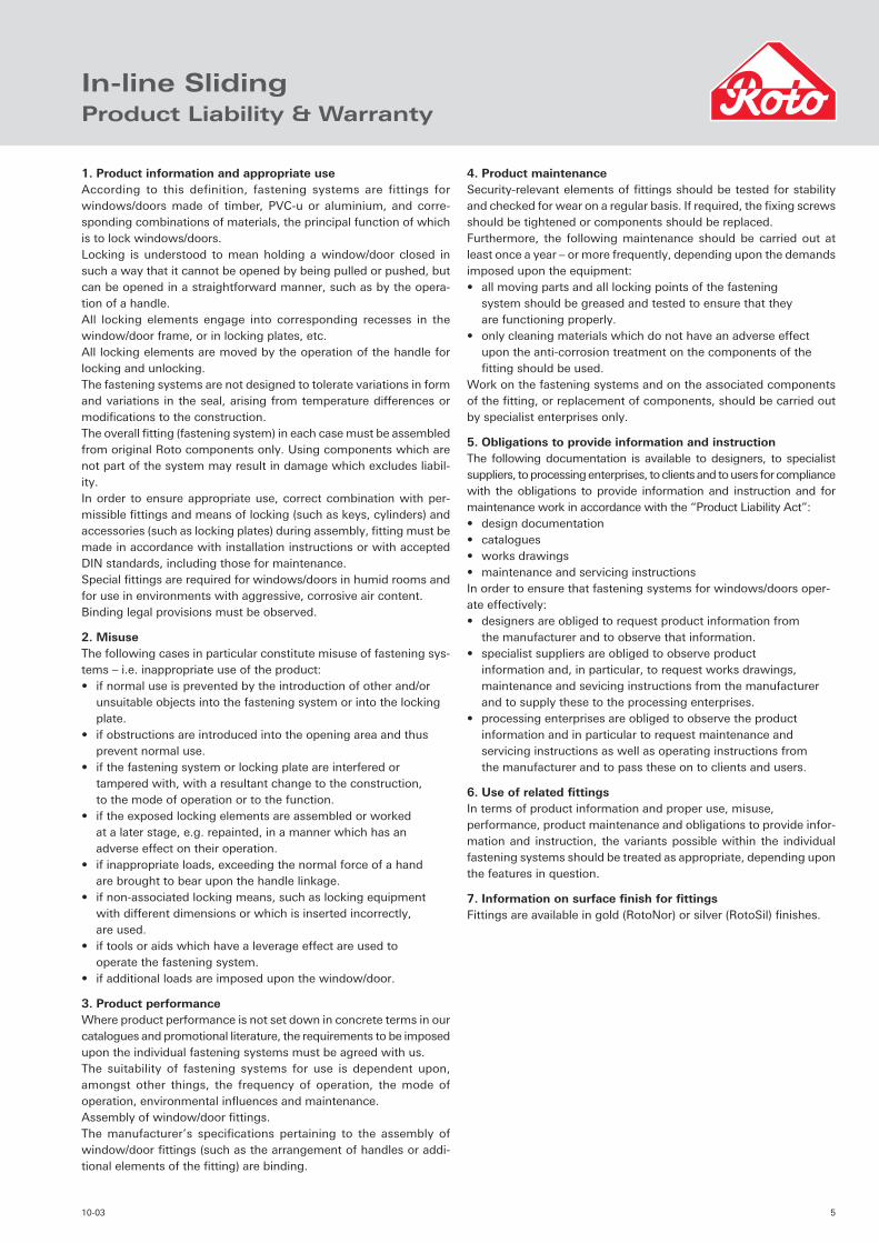
1. Product information and appropriate useAccording to this definition, fastening systems are fittings for windows/doors made of timber, PVC-u or aluminium, and corre-sponding combinations of materials, the principal function of which is to lock windows/doors.Locking is understood to mean holding a window/door closed in such a way that it cannot be opened by being pulled or pushed, but can be opened in a straightforward manner, such as by the opera-tion of a handle.All locking elements engage into corresponding recesses in the window/door frame, or in locking plates, etc.All locking elements are moved by the operation of the handle for locking and unlocking.The fastening systems are not designed to tolerate variations in form and variations in the seal, arising from temperature differences or modifi cations to the construction.The overall fi tting (fastening system) in each case must be assembled from original Roto components only. Using components which are not part of the system may result in damage which excludes liabil-ity.In order to ensure appropriate use, correct combination with per-missible fi ttings and means of locking (such as keys, cylinders) and accessories (such as locking plates) during assembly, fi tting must be made in accordance with installation instructions or with accepted DIN standards, including those for maintenance.Special fi ttings are required for windows/doors in humid rooms and for use in environments with aggressive, corrosive air content.Binding legal provisions must be observed.
2. MisuseThe following cases in particular constitute misuse of fastening sys-tems – i.e. inappropriate use of the product:• if normal use is prevented by the introduction of other and/or unsuitable objects into the fastening system or into the locking plate.• if obstructions are introduced into the opening area and thus prevent normal use.• if the fastening system or locking plate are interfered or tampered with, with a resultant change to the construction, to the mode of operation or to the function.• if the exposed locking elements are assembled or worked at a later stage, e.g. repainted, in a manner which has an adverse effect on their operation.• if inappropriate loads, exceeding the normal force of a hand are brought to bear upon the handle linkage.• if non-associated locking means, such as locking equipment with different dimensions or which is inserted incorrectly, are used.• if tools or aids which have a leverage effect are used to operate the fastening system.• if additional loads are imposed upon the window/door.
3. Product performanceWhere product performance is not set down in concrete terms in our catalogues and promotional literature, the requirements to be imposed upon the individual fastening systems must be agreed with us.The suitability of fastening systems for use is dependent upon, amongst other things, the frequency of operation, the mode of operation, environmental infl uences and maintenance.Assembly of window/door fi ttings.The manufacturer’s specifi cations pertaining to the assembly of window/door fi ttings (such as the arrangement of handles or addi-tional elements of the fi tting) are binding.
4. Product maintenanceSecurity-relevant elements of fi ttings should be tested for stability and checked for wear on a regular basis. If required, the fi xing screws should be tightened or components should be replaced.Furthermore, the following maintenance should be carried out at least once a year – or more frequently, depending upon the demands imposed upon the equipment:• all moving parts and all locking points of the fastening system should be greased and tested to ensure that they are functioning properly.• only cleaning materials which do not have an adverse effect upon the anti-corrosion treatment on the components of the fi tting should be used.Work on the fastening systems and on the associated components of the fi tting, or replacement of components, should be carried out by specialist enterprises only.
5. Obligations to provide information and instructionThe following documentation is available to designers, to specialist suppliers, to processing enterprises, to clients and to users for compliance with the obligations to provide information and instruction and for maintenance work in accordance with the “Product Liability Act”:• design documentation• catalogues• works drawings• maintenance and servicing instructionsIn order to ensure that fastening systems for windows/doors oper-ate effectively:• designers are obliged to request product information from the manufacturer and to observe that information.• specialist suppliers are obliged to observe product information and, in particular, to request works drawings, maintenance and sevicing instructions from the manufacturer and to supply these to the processing enterprises.• processing enterprises are obliged to observe the product information and in particular to request maintenance and servicing instructions as well as operating instructions from the manufacturer and to pass these on to clients and users.
6. Use of related fi ttingsIn terms of product information and proper use, misuse, performance, product maintenance and obligations to provide infor-mation and instruction, the variants possible within the individual fastening systems should be treated as appropriate, depending upon the features in question.
7. Information on surface fi nish for fi ttings Fittings are available in gold (RotoNor) or silver (RotoSil) fi nishes.
In-line SlidingProduct Liability & Warranty

6 10-03
In-line SlidingHardware Overview
b
b
b
d d
d
In-line Sliding espagnolettes for windows & doors
Strikers (one piece or individual)
Handle
Fixed height, single rollers
Adjustable, tandem rollers
In-line Sliding espagnolettes pages 11 – 15
This option shown
b
b
b
d
d
In-line Sliding espagnolettes for windows & doors
Strikers (one piece or individual)
Handle
Pop-up handle
Fixed height, single rollers
Adjustable, tandem rollers
In-line Sliding espagnolettes pages 11 – 15
710-03
b
d d
b
b
b
b
d
In-line Sliding espagnolettes for doors (locking & non-locking)
Strikers (one piece or individual)
Handles (locking & non-locking)
Fixed height, single rollers
Adjustable, tandem rollers
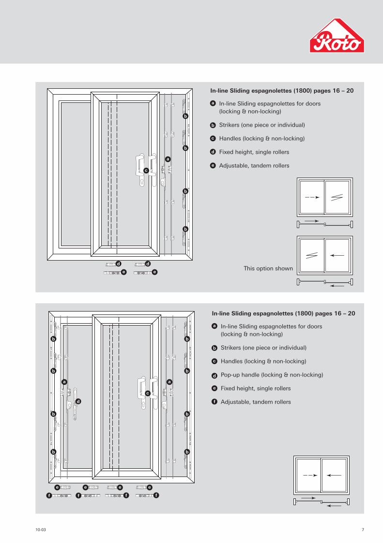
In-line Sliding espagnolettes (1800) pages 16 – 20
This option shown
b
b
b
b
b
b
b
b
b
d
d
In-line Sliding espagnolettes for doors (locking & non-locking)
Strikers (one piece or individual)
Handles (locking & non-locking)
Pop-up handle (locking & non-locking)
Fixed height, single rollers
Adjustable, tandem rollers
In-line Sliding espagnolettes (1800) pages 16 – 20
8 10-03
In-line SlidingHardware Overview
b
b
b
d d
d
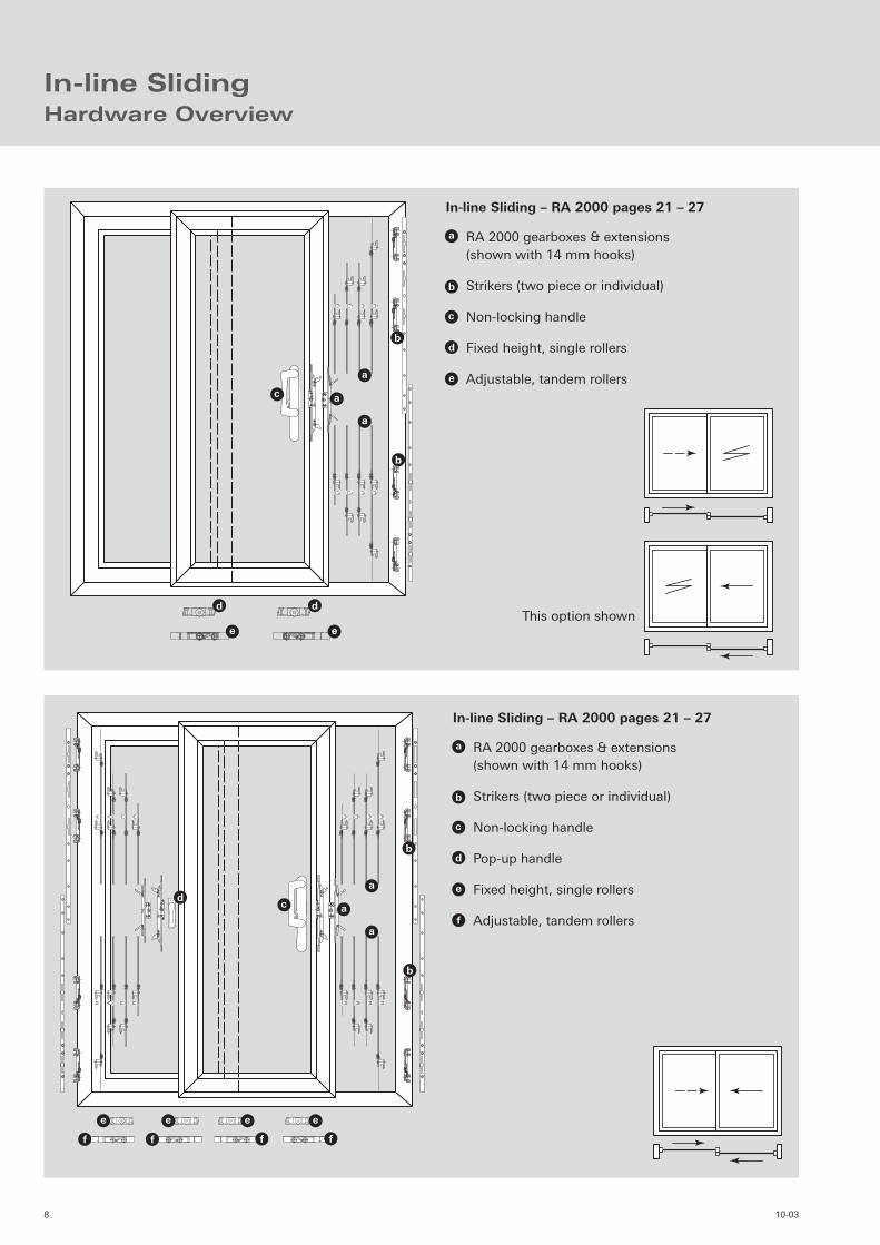
RA 2000 gearboxes & extensions(shown with 14 mm hooks)
Strikers (two piece or individual)
Non-locking handle
Fixed height, single rollers
Adjustable, tandem rollers
In-line Sliding – RA 2000 pages 21 – 27
This option shown
d
b
b
b
d
RA 2000 gearboxes & extensions(shown with 14 mm hooks)
Strikers (two piece or individual)
Non-locking handle
Pop-up handle
Fixed height, single rollers
Adjustable, tandem rollers
In-line Sliding – RA 2000 pages 21 – 27
910-03
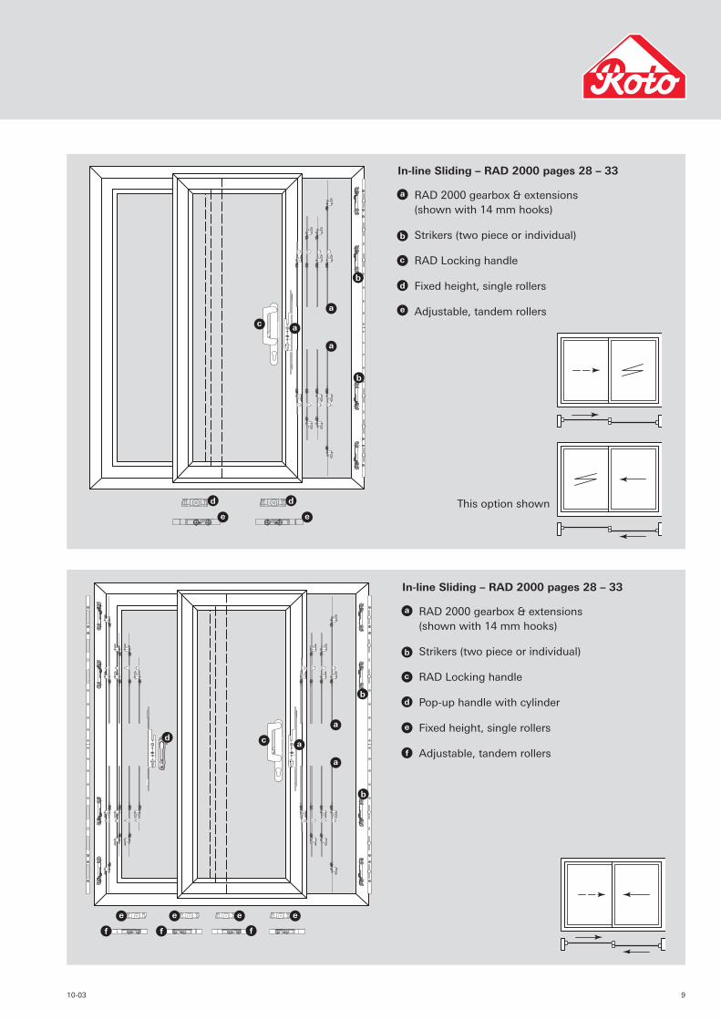
This option shown
b
b
b
d d
d
RAD 2000 gearbox & extensions(shown with 14 mm hooks)
Strikers (two piece or individual)
RAD Locking handle
Fixed height, single rollers
Adjustable, tandem rollers
In-line Sliding – RAD 2000 pages 28 – 33
b
b
b
d
d
RAD 2000 gearbox & extensions(shown with 14 mm hooks)
Strikers (two piece or individual)
RAD Locking handle
Pop-up handle with cylinder
Fixed height, single rollers
Adjustable, tandem rollers
In-line Sliding – RAD 2000 pages 28 – 33

10 10-03
1110-03
In-line Sliding EspagnolettesGeneral Design Description
Sliding Window Espagnolettes
These espagnolettes provide solutions for in-line sliding windows. They are based on the same design as the standard espagnolette for outward opening windows, but incorporate additional elements, such as an anti lift pin and hooks.
Also available is a range of one piece extensions which are 600 mm long and incorporate an anti lift pin and two hooks of varying size.
• 7 or 17 mm backsets available
• Faceplate width 16 mm
• One piece lock assembly
• Four point security including adjustable mushroom cams and sliding hooks of varying sizes.
• Anti lift pin incorporated on all designs
• One piece or individual striker options
• All surfaces are coated with either a gold (RotoNor) or silver (RotoSil) fi nish.
Sliding Door Espagnolettes
• 17 mm backset
• Faceplate width 16 mm
• One piece lock assembly
• Four point security including 8 mm adjustable, mushroom cams, sliding hooks or claws.
• Anti lift pin incorporated on all designs
• One piece or individual striker options
• All surfaces are coated with either a gold (RotoNor) or silver (RotoSil) fi nish.
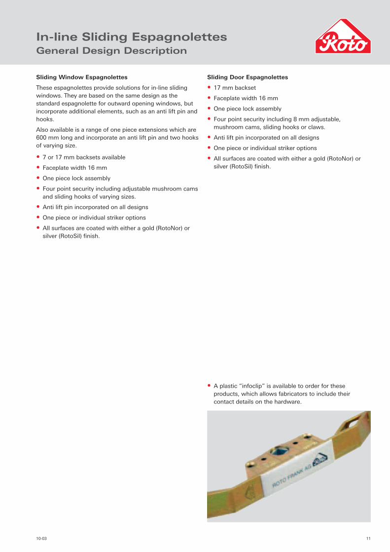
• A plastic “infoclip” is available to order for these products, which allows fabricators to include their contact details on the hardware.

12 10-03
In-line Sliding EspagnolettesLocking System with Adjustable CamsOrder Details
17 mm backset espagnolette with adjustable cam & pin
17 mm backset, 8 mm adjustable cam & pin
Application range (mm)
Faceplate length (mm)
Packing quantity
No. ofstrikers
RotoNorPart number
RotoSilPart number
240 – 400 240 1000 2 298 102 –
400 – 600 400 700 2 298 103 –
600 – 800 600 720 2 298 104 –
800 – 1000 800 720 2 298 105 –
1000 – 1200 1000 720 3 298 106 –
1200 – 1800 1200 720 3 298 107 –
7 mm backset espagnolette with adjustable cam & pin
7 mm backset, 8 mm adjustable cam & pin
Application range (mm)
Faceplate length (mm)
Packing quantity
No. ofstrikers
RotoNorPart number
RotoSilPart number
400 – 600 400 700 2 309 753 329 051
600 – 800 600 720 2 309 754 329 052
800 – 1000 800 720 2 309 755 329 053
1000 – 1200 1000 720 3 309 756 329 054
1200 – 1800 1200 720 3 309 757 329 055

1310-03
Locking System with Adjustable CamsTechnical Details
8
18
Travel
43L
C
A
B
50
7
Adjustable cam(± 1 mm)
17 mm backset
LL
Travel
18
B
A
7 mm backset
7
43 50
C
Adjustable cam(± 1 mm)8
17 mm backset 7 mm backset
L A B C
240 mm without 88 mm 72 mm
400 mm without 143 mm 127 mm
600 mm without 243 mm 227 mm
800 mm without 343 mm 327 mm
1000 mm 128 mm 443 mm 427 mm
1200 mm 128 mm 543 mm 527 mm
L A B C
400 mm without 143 mm 127 mm
600 mm without 243 mm 227 mm
800 mm without 343 mm 327 mm
1000 mm 128 mm 443 mm 427 mm
1200 mm 128 mm 543 mm 527 mm

14 10-03
In-line Sliding Espagnolettes600 Locking System with HooksOrder Details
17 mm backset espagnolette with 14 mm hooks
Faceplate length (mm)
Packing quantity
No. ofstrikers
RotoNorPart number
RotoSilPart number
17 mm backset & two 5 mm hooks
600 600 2 or 1 320 353 328 932
17 mm backset & two 14 mm hooks
600 600 1 piece 320 356 328 973
The one piece 600 mm striker can be used with either item but individual strikers can only be used with the 5 mm hooks. Refer to table on pages 46 & 47
1510-03
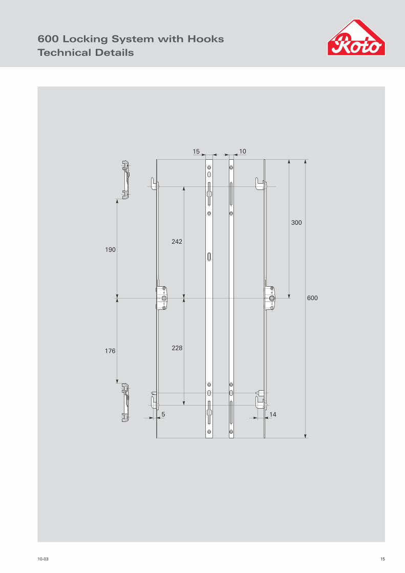
600 Locking System with HooksTechnical Details
300
600
14
228
5
190
176
242
15 10

16 10-03
In-line Sliding Espagnolettes1800 Non-Locking SystemOrder Details
1 52 3 4
No. of strikers
RotoNorPart No.
RotoSilPart No.
Pos. 11800 espag. with four cams and a pin. (7 mm backset)
4 315 600 329 057
Pos. 21800 espag. with four cams and a pin. (17 mm backset)
4 or 1 315 601 328 974
Pos. 31800 espag. with four 5 mm hooks and a pin. (17 mm backset)
4 or 1 319 386 328 991
Pos. 41800 espag. with four 14 mm hooks and a pin. (17 mm backset)
1 piece 319 388 328 992
Pos. 5One piece striker can be used with positions 2, 3 or 4.
Individual strikes are also available for positions 1, 2 or 3. Refer to pages 46 & 47 for further information on strikers.

1710-03
1800 Non-Locking SystemTechnical Details
756
725
411
380
811
466
7
429
774
1800
900
900
808
17463
777
432
1510
18 10-03
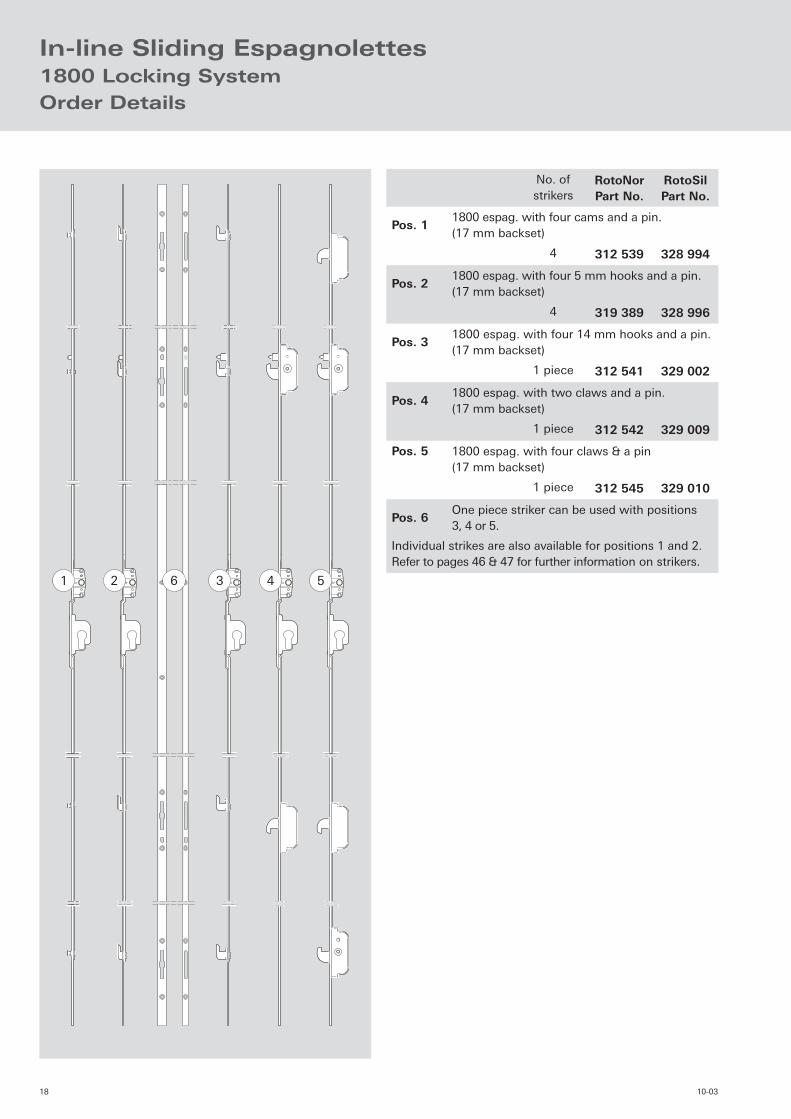
In-line Sliding Espagnolettes1800 Locking SystemOrder Details
1 52 36 4
No. of strikers
RotoNorPart No.
RotoSilPart No.
Pos. 11800 espag. with four cams and a pin. (17 mm backset)
4 312 539 328 994
Pos. 21800 espag. with four 5 mm hooks and a pin. (17 mm backset)
4 319 389 328 996
Pos. 31800 espag. with four 14 mm hooks and a pin. (17 mm backset)
1 piece 312 541 329 002
Pos. 41800 espag. with two claws and a pin. (17 mm backset)
1 piece 312 542 329 009
Pos. 5 1800 espag. with four claws & a pin(17 mm backset)
1 piece 312 545 329 010
Pos. 6One piece striker can be used with positions 3, 4 or 5.
Individual strikes are also available for positions 1 and 2. Refer to pages 46 & 47 for further information on strikers.
1910-03
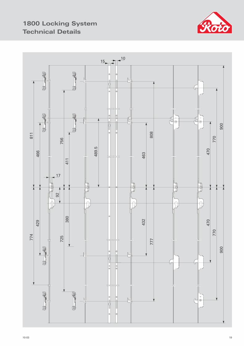
1800 Locking SystemTechnical Details
1510
811
774
466
429
17
92
756
725
411
380
432
777
463
489.5
808
900
770
470
900
770
470

20 10-03
In-line Sliding EspagnolettesRouting Details
62 mm 62 mm
ø10
ø12
ø10
21.5
21.5
Centre spindle
Gea
rbox
ro
uti
ng
len
gth
50 mm
12 mm7 mm Espag. backset
92
21.5
21.5
ø10
ø10
ø12
ø20
ø20
16
1715
50 65
76 91
108.5
15
Standard & 600 Espagnolettes
1800 Espagnolettes

2110-03
In-line Sliding Shootbolt EspagnolettesGeneral Design Description
RA2000
• Designed for use on timber, PVCu and aluminium systems with a minimum eurogroove depth of 5 mm.
• Available in 7, 20 or 22 mm backsets.
• Faceplate width 16 mm.
• Routing length for the gearbox is only 60 mm x 9 mm and if this dimension is adhered to, barbs on the gearbox grip within the routed slot.
• Fixing screws are positioned well clear of the routed slot ensuring secure fi tting every time.
• An arrow on the gearbox indicates direction of the handle when in the closed position.
• Precise design of internal components ensures a smooth and regular operation.
• A ‘snap down’ fi xing plate retains the extensions and ensures the drive rod is held in position. These are then held in place with screws providing secure protection against any attack.
• All parts are pre-set in the open position for easy fi tting. Initial operation of the handle releases the mechanism.
• All surfaces are coated with a gold (RotoNor) fi nish.
RAD2000
• The general design description lists characteristics of the Roto RAD2000 sliding system.
• Designed for use on timber, PVCu and aluminium systems with a minimum eurogroove depth of 5 mm.
• Available in 17 mm or 25 mm backsets.
• Faceplate width 16 mm.
• Precise design of internal components ensures a smooth and regular operation.
• All parts are pre-set in the open position for easy fi tting.
• Initial operation of the handle releases the mechanism.
• All surfaces are coated with a gold (RotoNor) fi nish.
22 10-03
6
6 5
5
4
4 3
3
1 2
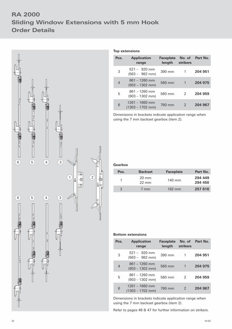
RA 2000Sliding Window Extensions with 5 mm HookOrder Details
Pos. Application range
Faceplatelength
No. of strikers
Part No.
3 521 – 920 mm
(563 – 962 mm)390 mm 1 204 951
4 861 – 1260 mm
(903 – 1302 mm)560 mm 1 204 975
5 861 – 1260 mm
(903 – 1302 mm)560 mm 2 204 959
61261 – 1660 mm
(1303 – 1702 mm)760 mm 2 204 967
Top extensions
Dimensions in brackets indicate application range when using the 7 mm backset gearbox (item 2).
Dimensions in brackets indicate application range when using the 7 mm backset gearbox (item 2).
Refer to pages 46 & 47 for further information on strikers.
Pos. Backset Faceplate Part No.
120 mm22 mm
140 mm294 449294 450
2 7 mm 182 mm 257 616
Gearbox
Pos. Application range
Faceplatelength
No. of strikers
Part No.
3 521 – 920 mm
(563 – 962 mm)390 mm 1 204 951
4 861 – 1260 mm
(903 – 1302 mm)560 mm 1 204 975
5 861 – 1260 mm
(903 – 1302 mm)560 mm 2 204 959
61261 – 1660 mm
(1303 – 1702 mm)760 mm 2 204 967
Bottom extensions
2310-03
70
70
(75
)(1
07
)
46
0 (
46
5)
39
0 (
39
5)
57
0 (
57
5) 630
(6
35
)
736
(7
41
)
830
(8
35
)
46
0 (
49
7)39
0 (
42
7)
51
8 (
52
3)
51
8 (
52
3)
338
(34
3)
338
(34
3)
68
4 (
68
9)
57
0 (
60
7)
630
(6
67
)
736
(7
73)
830
(8
67
)68
4 (
68
9)
Can
be
cut
20
0 m
m
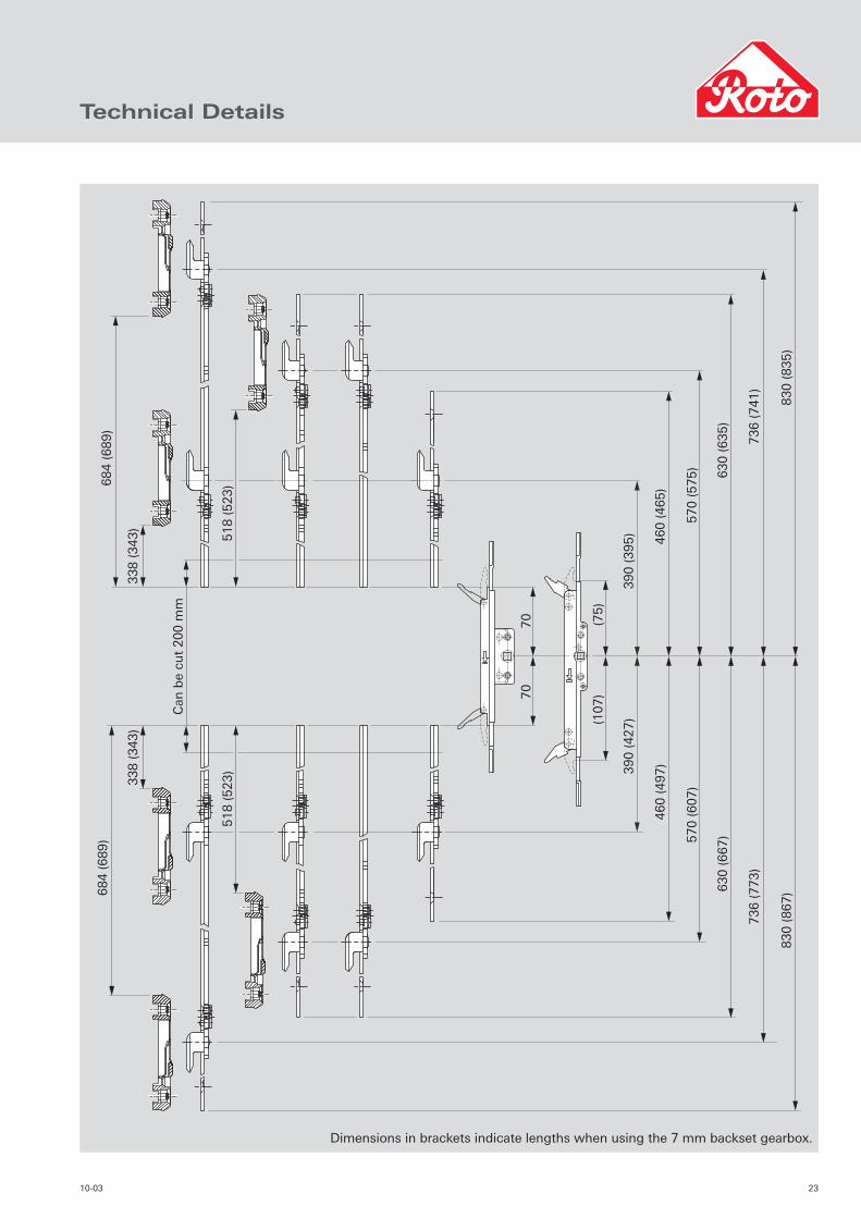
Technical Details
Dimensions in brackets indicate lengths when using the 7 mm backset gearbox.
24 10-03
6
A
A
6 5
5
4
4 3
3
1
2
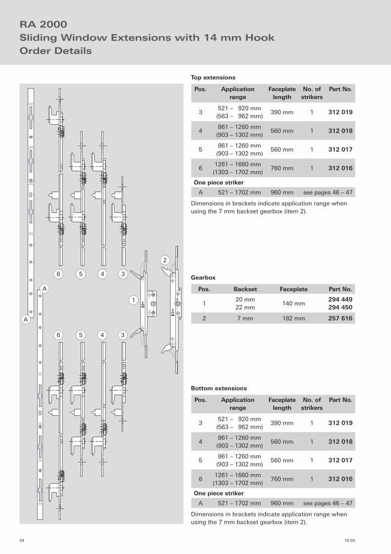
RA 2000Sliding Window Extensions with 14 mm HookOrder Details
Pos. Applicationrange
Faceplatelength
No. of strikers
Part No.
3 521 – 920 mm
(563 – 962 mm)390 mm 1 312 019
4 861 – 1260 mm
(903 – 1302 mm)560 mm 1 312 018
5 861 – 1260 mm
(903 – 1302 mm)560 mm 1 312 017
61261 – 1660 mm
(1303 – 1702 mm)760 mm 1 312 016
One piece striker
A 521 – 1702 mm 960 mm see pages 46 – 47
Top extensions
Dimensions in brackets indicate application range when using the 7 mm backset gearbox (item 2).
Pos. Backset Faceplate Part No.
120 mm22 mm
140 mm294 449294 450
2 7 mm 182 mm 257 616
Gearbox
Pos. Applicationrange
Faceplatelength
No. of strikers
Part No.
3 521 – 920 mm
(563 – 962 mm)390 mm 1 312 019
4 861 – 1260 mm
(903 – 1302 mm)560 mm 1 312 018
5 861 – 1260 mm
(903 – 1302 mm)560 mm 1 312 017
61261 – 1660 mm
(1303 – 1702 mm)760 mm 1 312 016
One piece striker
A 521 – 1702 mm 960 mm see pages 46 – 47
Bottom extensions
Dimensions in brackets indicate application range when using the 7 mm backset gearbox (item 2).

2510-03
70
70
(75)
(107)
460 (
465)
390 (
395)
419 (
424)
570 (
575) 630 (
635)
736 (
741)
830 (
835)
460 (
497)390 (
427)
130 (
95)
630 -
830 (
635 -
835)
570 (
607)
630 (
667)
736 (
773)
830 (
867)
630 -
830 (
665 -
865)
Can
be
cut
200 m
m
Can
be
cut
200 m
m
419 (
424)
22
2
22
2
130 (
125)
Can
be
cut
200 m
m
Technical Details
Dimensions in brackets indicate lengths when using the 7 mm backset gearbox.
26 10-03
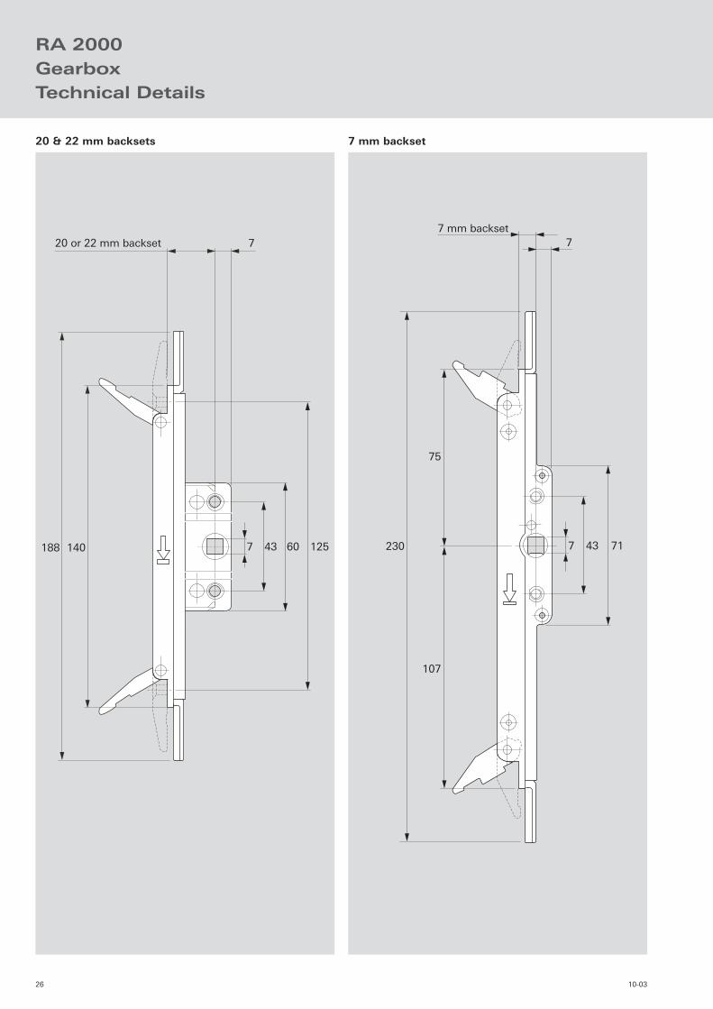
RA 2000GearboxTechnical Details
140188 7 43 60 125
20 or 22 mm backset 7
7 43 71
75
107
7 mm backset7
230
20 & 22 mm backsets 7 mm backset
2710-03
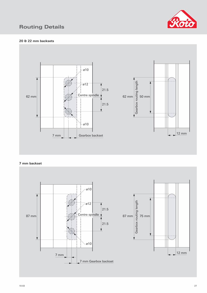
Routing Details
62 mm 62 mm
ø10
ø12
ø10
21.5
21.5
Centre spindle
Gea
rbox
ro
uti
ng
len
gth
50 mm
12 mm7 mm Gearbox backset
87 mm
21.5
21.5
Centre spindle
ø12
7 mm
7 mm Gearbox backset
87 mm
Gea
rbox
ro
uti
ng
len
gth
75 mm
12 mm
ø10
ø10
20 & 22 mm backsets
7 mm backset
28 10-03
1
3
3
2
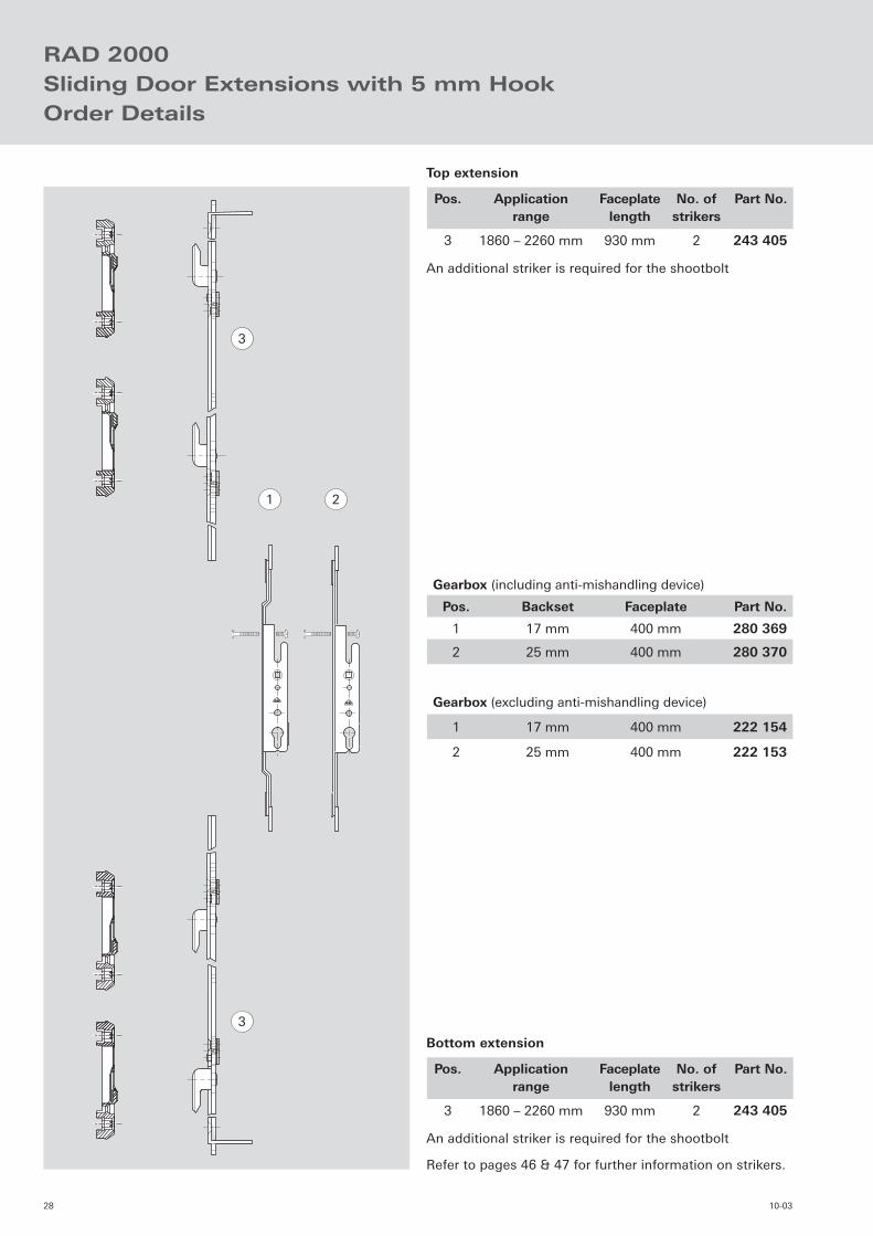
RAD 2000Sliding Door Extensions with 5 mm HookOrder Details
Pos. Application range
Faceplatelength
No. ofstrikers
Part No.
3 1860 – 2260 mm 930 mm 2 243 405
Top extension
Gearbox (including anti-mishandling device)
Pos. Backset Faceplate Part No.
1 17 mm 400 mm 280 369
2 25 mm 400 mm 280 370
Gearbox (excluding anti-mishandling device)
1 17 mm 400 mm 222 154
2 25 mm 400 mm 222 153
An additional striker is required for the shootbolt
Pos. Application range
Faceplatelength
No. ofstrikers
Part No.
3 1860 – 2260 mm 930 mm 2 243 405
Bottom extension
An additional striker is required for the shootbolt
Refer to pages 46 & 47 for further information on strikers.

2910-03
200
303
303
930
589
589
200
930
can
be
cut
200 m
m
Centre gearbox
251
251
537
5371130
1130
Technical Details

30 10-03
RAD 2000Sliding Door Extensions with ClawsOrder Details
1
3 5 6 7
5 6 7
4
4 3
2
Gearbox (including anti-mishandling device)
Pos. Backset Faceplate Part No.
1 17 mm 400 mm 280 369
2 25 mm 400 mm 280 370
Gearbox (excluding anti-mishandling device)
1 17 mm 400 mm 222 154
2 25 mm 400 mm 222 153
Top extension
Pos. Applicationrange
Faceplatelength
No. ofstrikers
Part No.
3 1520 – 1920 mm 760 mm 1 312 014
Top striker
4 760 – 960 mm 960 mm see pages 46–47
Shootbolts
5 – 135 mm 1 243 009
6 – 135 mm 1 224 062
7 – 200 mm 1 224 065
The application ranges stated do not include the shootbolts
Bottom extension
Pos. Applicationrange
Faceplatelength
No. ofstrikers
Part No.
3 1520 – 1920 mm 760 mm 1 312 014
Bottom striker
4 760 – 960 mm 960 mm see pages 46–47
Shootbolts
5 – 135 mm 1 243 009
6 – 135 mm 1 224 062
7 – 200 mm 1 224 065
The application ranges stated do not include the shootbolts
3110-03
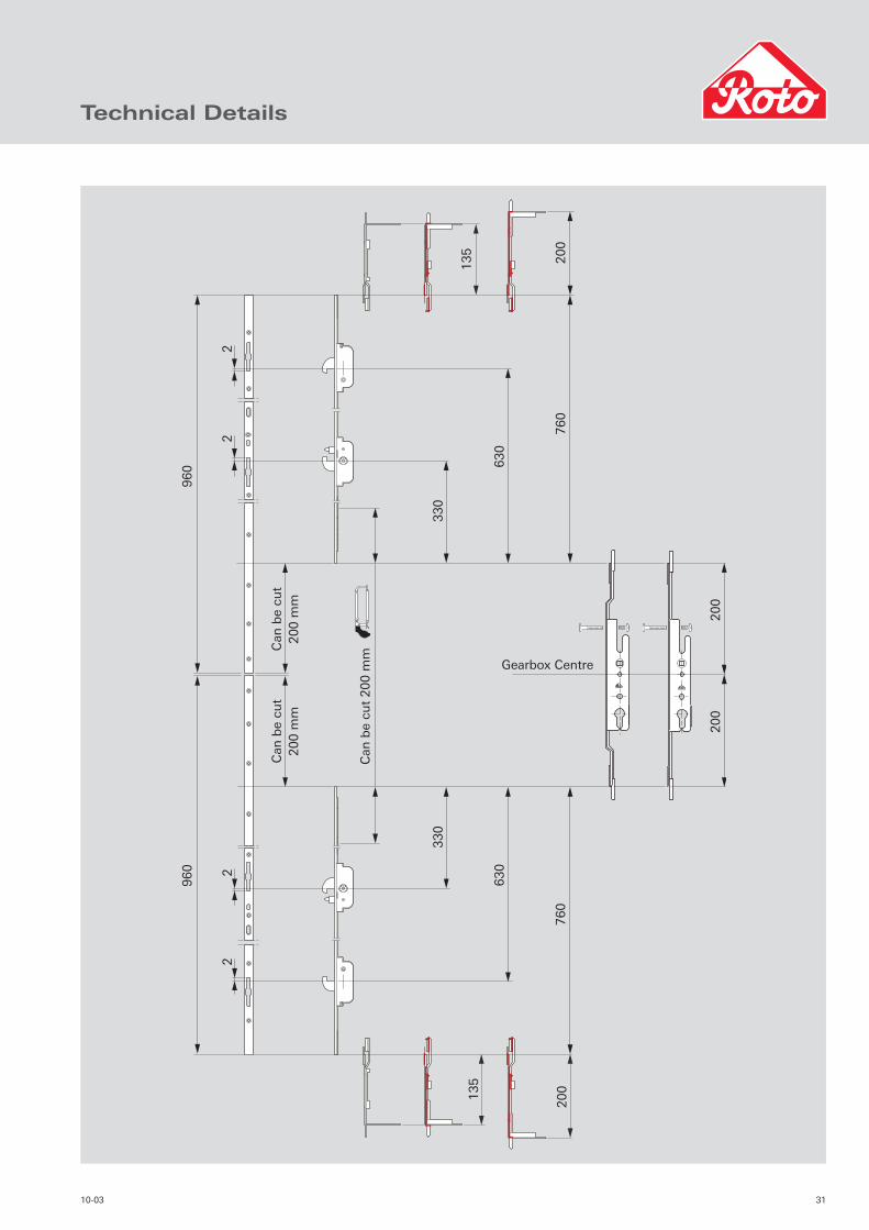
Technical Details
Gearbox Centre
20
02
00
20
07
60
630
330
76
0
135
20
0135
630
330
Can
be
cut
20
0 m
m
Can
be
cut
20
0 m
m
22
22
Can
be
cut
20
0 m
m
96
09
60
32 10-03
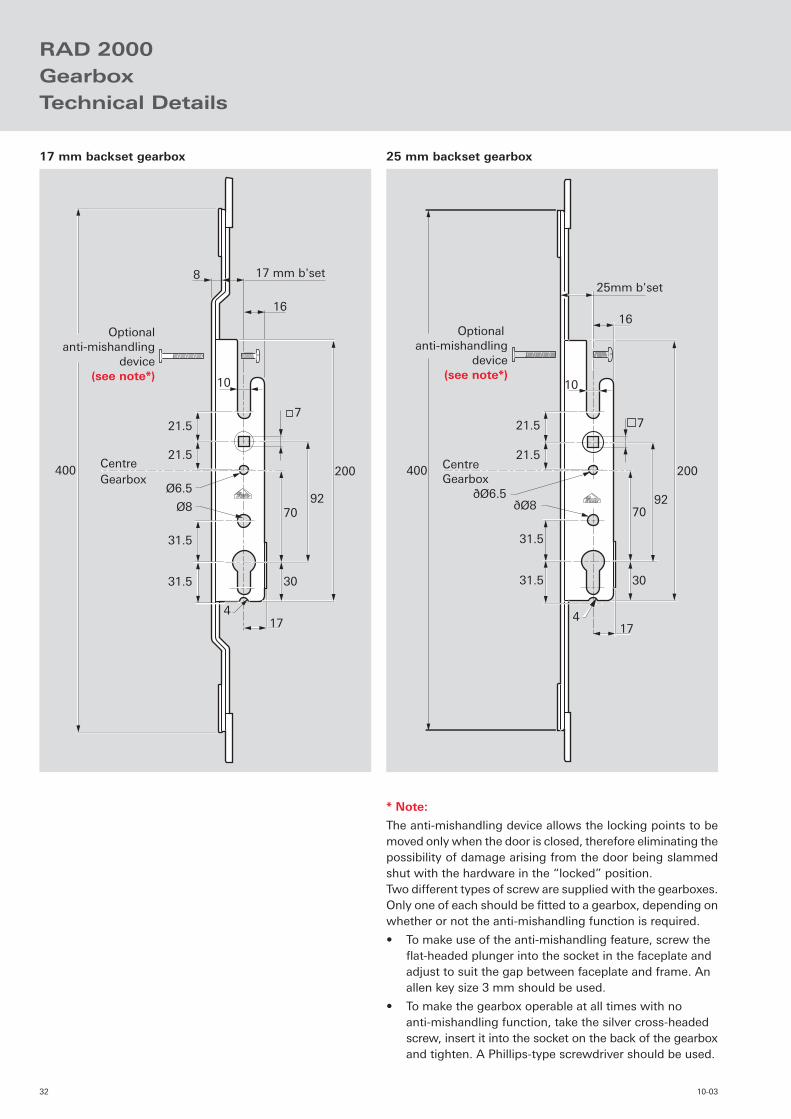
Optionalanti-mishandling
device(see note*) 10
8 17 mm b'set
16
31.5
31.5
17
30
7092
200
21.5
21.5400
CentreGearbox
7
Ø6.5
Ø8
4
Optional anti-mishandling
device(see note*)
31.5
31.5
21.5
21.5400
16
17
70
30
92
200
4
10
25mm b'set
CentreGearbox
7
ðØ6.5ðØ8
RAD 2000GearboxTechnical Details
* Note:
The anti-mishandling device allows the locking points to be moved only when the door is closed, therefore eliminating the possibility of damage arising from the door being slammed shut with the hardware in the “locked” position.Two different types of screw are supplied with the gearboxes. Only one of each should be fi tted to a gearbox, depending on whether or not the anti-mishandling function is required.
• To make use of the anti-mishandling feature, screw the fl at-headed plunger into the socket in the faceplate and adjust to suit the gap between faceplate and frame. An allen key size 3 mm should be used.
• To make the gearbox operable at all times with no anti-mishandling function, take the silver cross-headed screw, insert it into the socket on the back of the gearbox and tighten. A Phillips-type screwdriver should be used.
17 mm backset gearbox 25 mm backset gearbox

3310-03
Ø 20
Backset
Lock case
16
92
122
220
Centre
spindle
Ø 20
Ø 20
15
22
0g
earb
ox
rou
tin
g le
ng
th
Routing Details

34 10-03
3510-03
In-line RollersSpecifi cation
Single Roller
Characteristics of the single roller:
• No routing required – 12 mm outer carriage locates in the eurogroove.
• Made of a zinc die cast body with acetal tyre.
• Available in two pre-set heights of 17 mm & 21 mm.
• Maximum sash weight of 50 kg.
• Yellow passivated fi nish to comply with requirements of the following standards:
• BS7479 Salt spray corrosion tests in artifi cial atmospheres.
• DIN50021 Spray tests with different sodium chloride solutions.
• Can be connected together to increase sash weight capability.
• prEN13126 pt15 (DRAFT) 20,000 cycles with a mass of 50 kg per pair or rollers.
Tandem Roller
The tandem roller is available in the following formats:
Standard 12 mm wide carriage Standard 14 mm wide carriage Slimline R (radiused track) 12 mm wide carriage Slimline V (“v” track) 12 mm wide carriage
Characteristics of the standard tandem rollers:
• Adjustable between 19 mm & 26 mm.
• Sash weight capability, 122 kg per pair of rollers.
Characteristics of the slimline rollers:
• Adjustment between 15 mm & 19 mm.
• Sash weight capability, 100 kg per pair of rollers.
Common characteristics:
• No routing required – outer carriage locates in the eurogroove.
• Yellow passivated fi nish to comply with requirements of the following standards:
• BS7479 Salt spray corrosion tests in artifi cial atmospheres.
• DIN50021 Spray tests with different sodium chloride solutions.
• Plastic end blocks, making it easier to locate height adjuster and fi xing screws.
• prEN13126 pt5 (DRAFT) 20,000 cycles with a mass of 120kg per roller.
As with all Roto products, a brand synonymous with quality, you are guaranteed a virtually maintenance free, smooth operating sliding patio door.
36 10-03
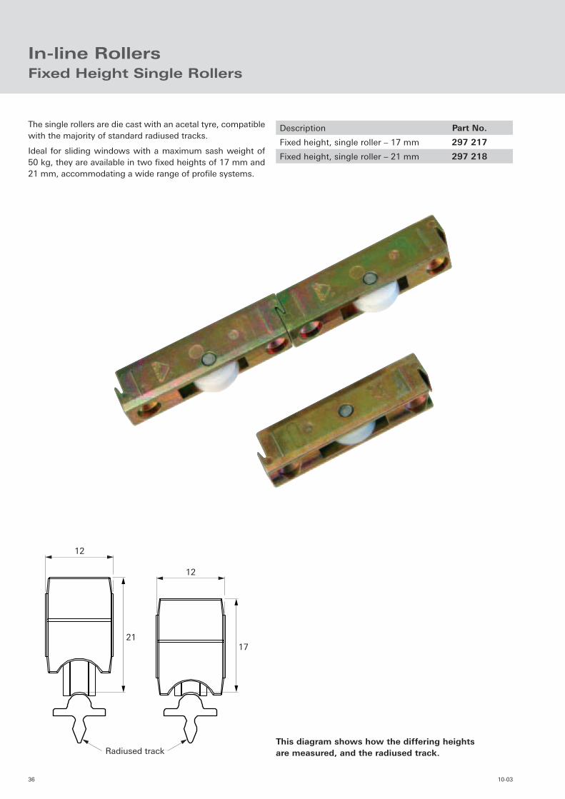
21
12
17
12
Radiused track
In-line RollersFixed Height Single Rollers
The single rollers are die cast with an acetal tyre, compatible with the majority of standard radiused tracks.
Ideal for sliding windows with a maximum sash weight of 50 kg, they are available in two fi xed heights of 17 mm and 21 mm, accommodating a wide range of profi le systems.
Description Part No.
Fixed height, single roller – 17 mm 297 217
Fixed height, single roller – 21 mm 297 218
This diagram shows how the differing heightsare measured, and the radiused track.

3710-03
"V" track Radiused "R" track
Radiused track
12 14
19 -
26 a
dju
stm
ent
Adjustable Tandem Rollers
Adjustable, standard tandem rollers
The standard roller is available in two widths; 12 mm for conventional eurogrooves and 14 mm for wider euro-grooves.
Both versions are adjustable from 19 mm to 26 mm and can carry a maximum sash weight of 120 kg.
Adjustment
Roller height adjustment tool.
Part Number: 263 088
Description Part No.
Adjustable, standard 12 mm roller 280 445
Adjustable, standard 14 mm roller 312 896
Description Part No.
Adjustable slimline “R” 12 mm roller 312 897
Adjustable slimline “V” 12 mm roller 297 216
Adjustable, slimline tandem rollers
The slimline roller is availble in two formats; one for a radi-used (“R”) track, and one for a “V” track.
Both versions are adjustable from 15 mm to 18.5 mm and can carry a maximum sash weight of 100 kg.
38 10-03
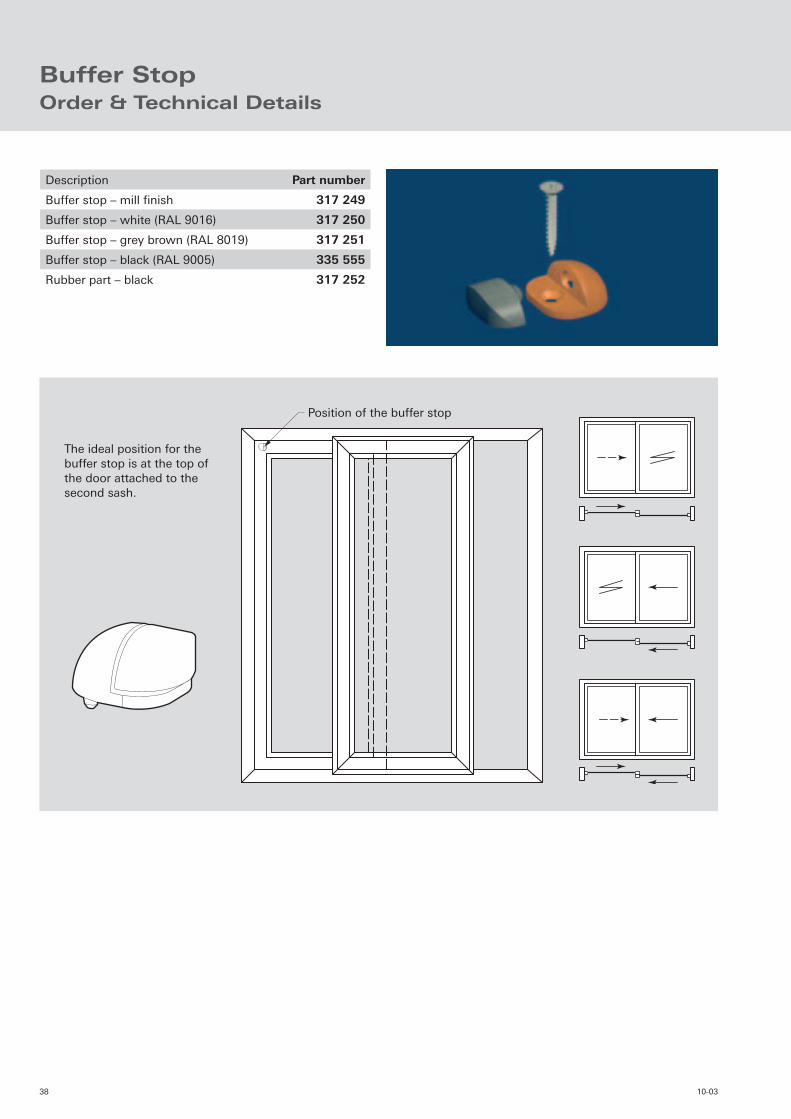
Buffer StopOrder & Technical Details
Position of the buffer stop
The ideal position for the buffer stop is at the top of the door attached to the second sash.
Description Part number
Buffer stop – mill fi nish 317 249
Buffer stop – white (RAL 9016) 317 250
Buffer stop – grey brown (RAL 8019) 317 251
Buffer stop – black (RAL 9005) 335 555
Rubber part – black 317 252

3910-03
Variation 01
Variation 02
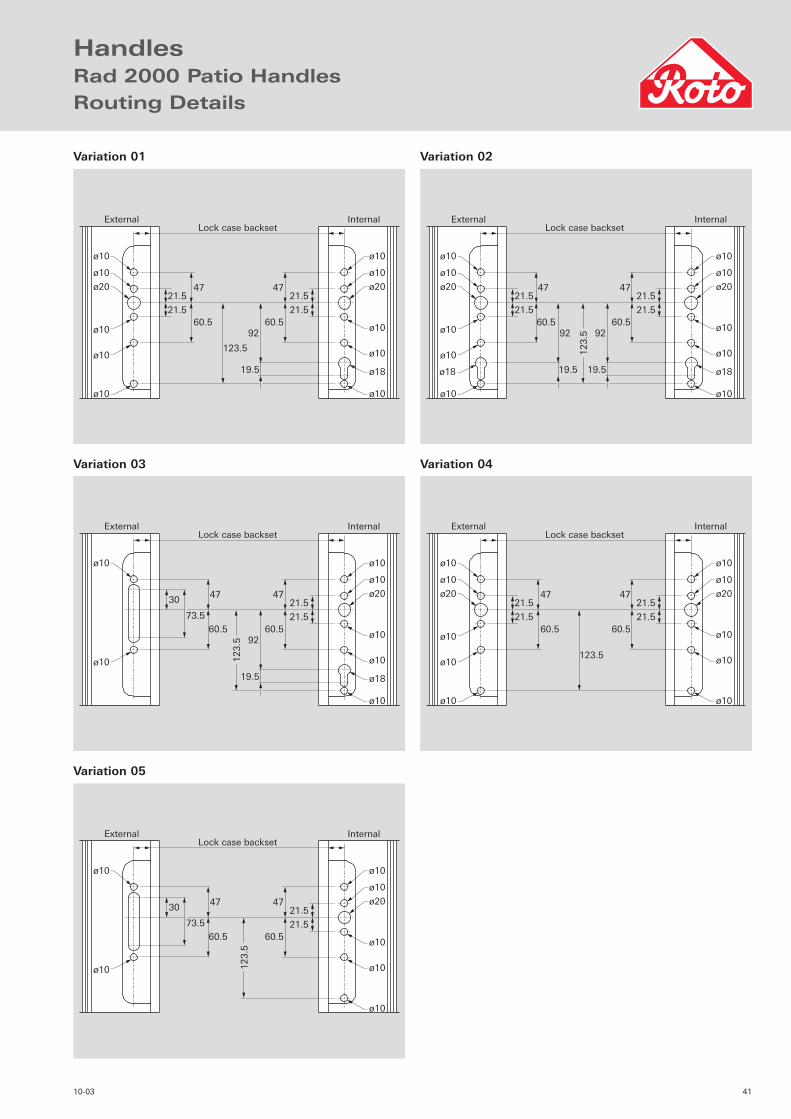
HandlesRad 2000 Patio Handles
Internal locking half cylinder.
This combination comprises of an external, non-locking handle and an internal locking handle with lever.
Descrition Part Number
White (RAL 9016) 291 131
Gold 291 144
Brown (RAL 8019) 262 644
Internal / external locking.
This combination comprises of internal and external locking handles with levers.
Descrition Part Number
White (RAL 9016) 291 137
Gold 291 146
Brown (RAL 8019) 262 645

40 10-03
Variation 04
Variation 05
Order Details
Variation 03Internal lever & cylinder / external fi nger pull.
This combination comprises of an external, fl ush mounted fi nger plate and an internal locking handle with lever.
Descrition Part Number
White (RAL 9016) 291 142
Gold 291 148
Brown (RAL 8019) 262 646
Non-locking lever inside.
This combination comprises of an external, non-locking handle and an internal non-locking handle with lever.
Descrition Part Number
White (RAL 9016) 291 140
Gold 291 147
Brown (RAL 8019) 262 647
Internal lever / external fi nger pull.
This combination comprises of an external, fl ush mounted fi nger plate and an internal non-locking handle with lever.
Descrition Part Number
White (RAL 9016) 291 143
Brown (RAL 8019) 262 648
4110-03
HandlesRad 2000 Patio HandlesRouting Details
ø10
ø10
ø10
ø10
ø10
ø20 ø20
ø10
ø10
ø10
ø18
ø10 ø10
21.5
21.5
21.5
21.5
47
60.5
47
92
19.5
60.5
123.5
Lock case backsetExternal Internal
ø10 ø10
ø10
ø20
ø10
ø10
ø10
ø10
21.5
21.5
4730
73.5
60.5
47
60.5
123.5
Lock case backsetExternal Internal
ø10 ø10
ø10
ø20
ø10
ø10
ø10
ø18
ø10
21.5
21.5
4730
73.5
60.5
47
92
19.5
60.5
123.5
Lock case backsetExternal Internal
ø10
ø10
ø10
ø10
ø10
ø20 ø20
ø10
ø10
ø10
ø18ø18
ø10 ø10
21.5
21.5
21.5
21.5
47
60.5
47
92
19.5
60.5
123.5
Lock case backset
92
19.5
External Internal
ø10
ø10
ø10
ø10
ø10
ø20 ø20
ø10
ø10
ø10
ø10 ø10
21.5
21.5
21.5
21.5
47
60.5
47
60.5
123.5
Lock case backsetExternal Internal
Variation 01
Variation 03
Variation 05
Variation 02
Variation 04

42 10-03
135
9
21.5
21.5
ø10
ø12
ø10
28
Backset dimension
Colour range
HandlesPop-up Handle without Cylinder
Description Part Number
White handle (RAL 9016) 312 766
ROH handle 312 769
Handle (RAL 9010) 323 275
Handle (RAL 8019) 323 277
Gold handle 323 279
Brushed stainless steel handle 323 280
Routing Details
Roto’s “pop-up” handle provides an ideal solution to the problem where two sliding sashes overlap. The handle sits almost fl ush with the profi le, but by simply lifting it from the backplate and turning, operation of the gearing is made possible with minimum effort. Once completed the handle can then be placed back in its original position, allowing the sliding sashes to overlap.
4310-03
Colour range
9
21.5
21.5
Backset dimension
ø10
ø12
ø10
ø10
28
161 145
113
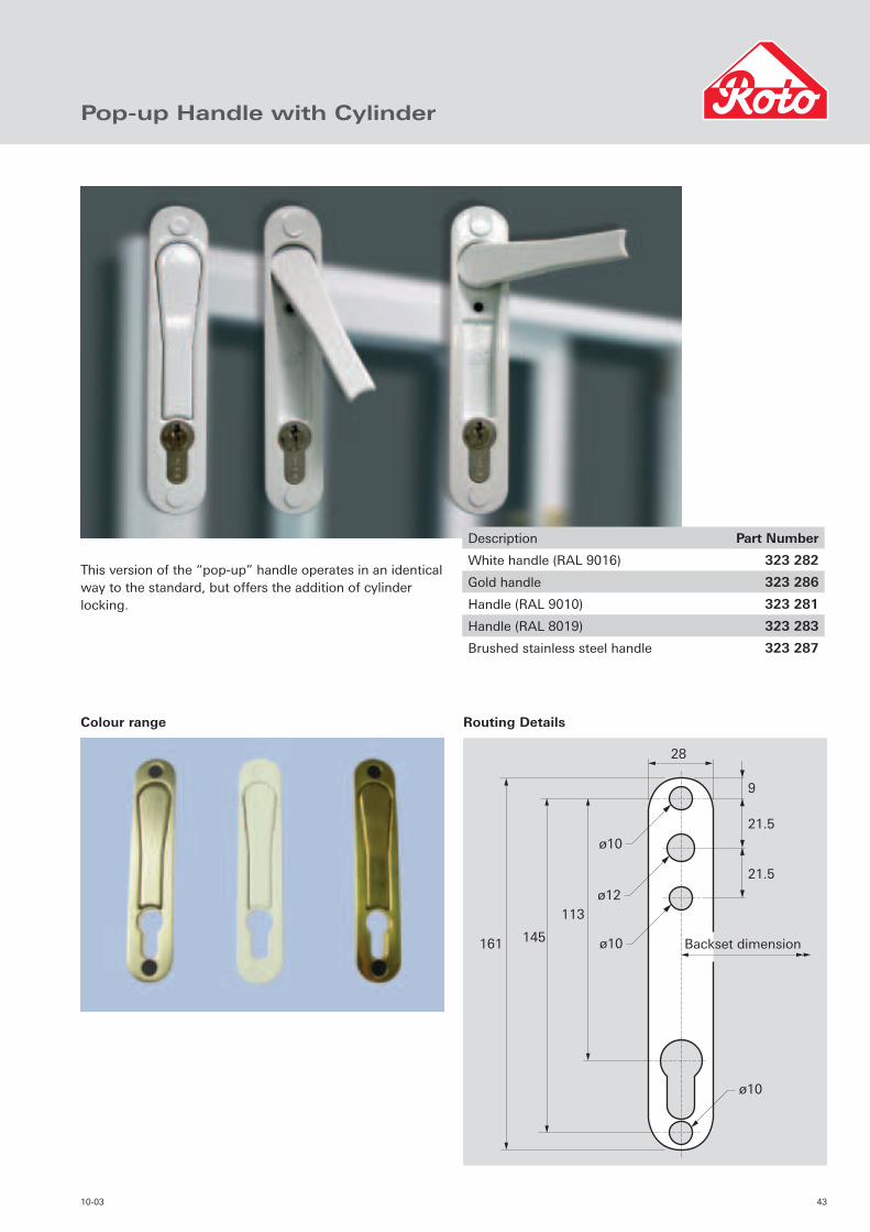
Pop-up Handle with Cylinder
Description Part Number
White handle (RAL 9016) 323 282
Gold handle 323 286
Handle (RAL 9010) 323 281
Handle (RAL 8019) 323 283
Brushed stainless steel handle 323 287
This version of the “pop-up” handle operates in an identical way to the standard, but offers the addition of cylinder locking.
Routing Details

44 10-03
4510-03
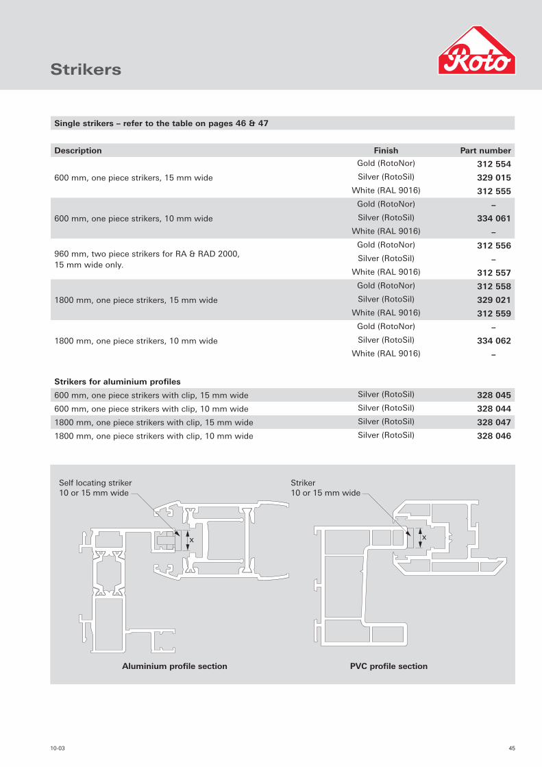
Strikers
Self locating striker 10 or 15 mm wide
Striker 10 or 15 mm wide
Aluminium profile section PVC profile section
xx
Single strikers – refer to the table on pages 46 & 47
Description Finish Part number
600 mm, one piece strikers, 15 mm wide
Gold (RotoNor) 312 554
Silver (RotoSil) 329 015
White (RAL 9016) 312 555
600 mm, one piece strikers, 10 mm wide
Gold (RotoNor) –
Silver (RotoSil) 334 061
White (RAL 9016) –
960 mm, two piece strikers for RA & RAD 2000, 15 mm wide only.
Gold (RotoNor) 312 556
Silver (RotoSil) –
White (RAL 9016) 312 557
1800 mm, one piece strikers, 15 mm wide
Gold (RotoNor) 312 558
Silver (RotoSil) 329 021
White (RAL 9016) 312 559
1800 mm, one piece strikers, 10 mm wide
Gold (RotoNor) –
Silver (RotoSil) 334 062
White (RAL 9016) –
Strikers for aluminium profi les
600 mm, one piece strikers with clip, 15 mm wide Silver (RotoSil) 328 045
600 mm, one piece strikers with clip, 10 mm wide Silver (RotoSil) 328 044
1800 mm, one piece strikers with clip, 15 mm wide Silver (RotoSil) 328 047
1800 mm, one piece strikers with clip, 10 mm wide Silver (RotoSil) 328 046
46 10-03
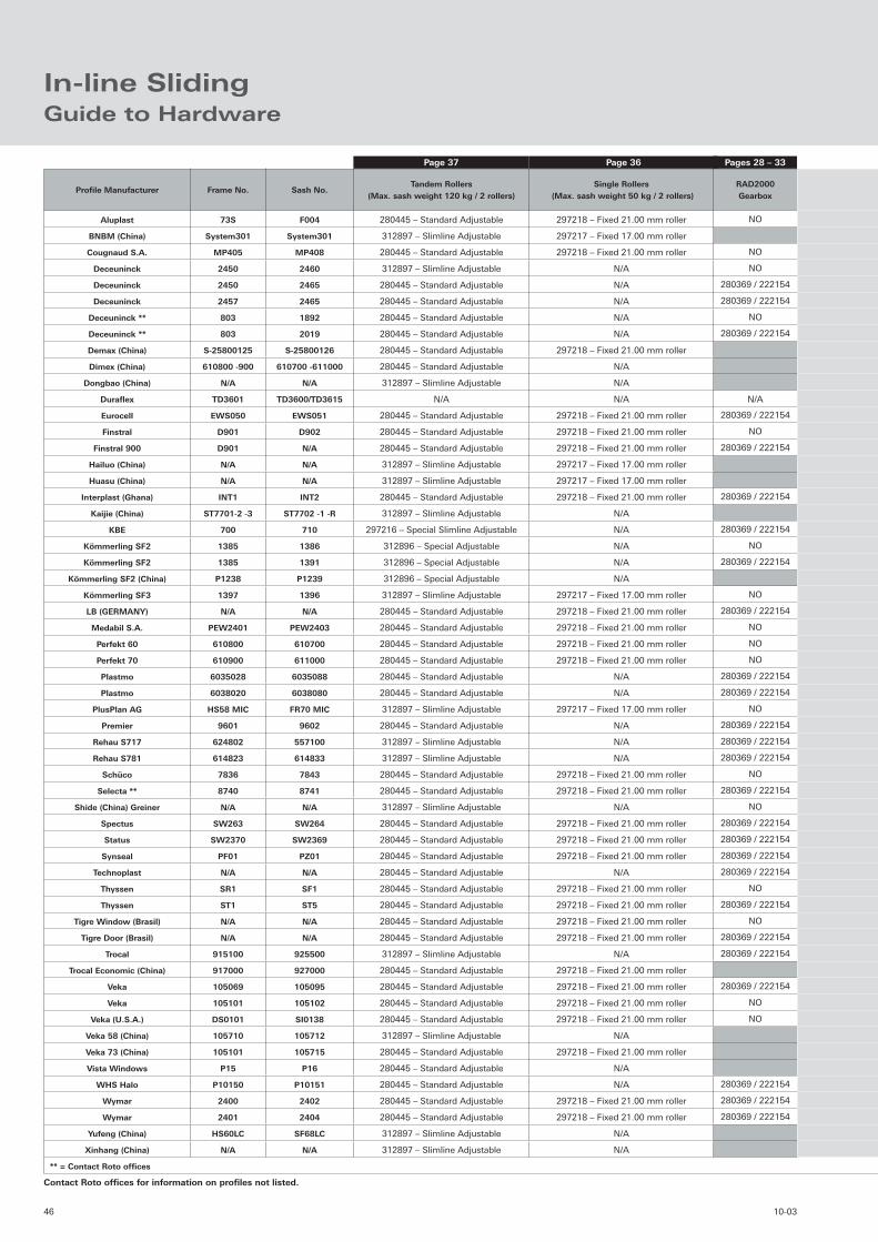
In-line SlidingGuide to Hardware
Profi le Manufacturer Frame No. Sash No.Tandem Rollers
(Max. sash weight 120 kg / 2 rollers)Single Rollers
(Max. sash weight 50 kg / 2 rollers)RAD2000Gearbox
Aluplast 73S F004 280445 – Standard Adjustable 297218 – Fixed 21.00 mm roller NO
BNBM (China) System301 System301 312897 – Slimline Adjustable 297217 – Fixed 17.00 mm roller
Cougnaud S.A. MP405 MP408 280445 – Standard Adjustable 297218 – Fixed 21.00 mm roller NO
Deceuninck 2450 2460 312897 – Slimline Adjustable N/A NO
Deceuninck 2450 2465 280445 – Standard Adjustable N/A 280369 / 222154
Deceuninck 2457 2465 280445 – Standard Adjustable N/A 280369 / 222154
Deceuninck ** 803 1892 280445 – Standard Adjustable N/A NO
Deceuninck ** 803 2019 280445 – Standard Adjustable N/A 280369 / 222154
Demax (China) S-25800125 S-25800126 280445 – Standard Adjustable 297218 – Fixed 21.00 mm roller
Dimex (China) 610800 -900 610700 -611000 280445 – Standard Adjustable N/A
Dongbao (China) N/A N/A 312897 – Slimline Adjustable N/A
Durafl ex TD3601 TD3600/TD3615 N/A N/A N/A
Eurocell EWS050 EWS051 280445 – Standard Adjustable 297218 – Fixed 21.00 mm roller 280369 / 222154
Finstral D901 D902 280445 – Standard Adjustable 297218 – Fixed 21.00 mm roller NO
Finstral 900 D901 N/A 280445 – Standard Adjustable 297218 – Fixed 21.00 mm roller 280369 / 222154
Hailuo (China) N/A N/A 312897 – Slimline Adjustable 297217 – Fixed 17.00 mm roller
Huasu (China) N/A N/A 312897 – Slimline Adjustable 297217 – Fixed 17.00 mm roller
Interplast (Ghana) INT1 INT2 280445 – Standard Adjustable 297218 – Fixed 21.00 mm roller 280369 / 222154
Kaijie (China) ST7701-2 -3 ST7702 -1 -R 312897 – Slimline Adjustable N/A
KBE 700 710 297216 – Special Slimline Adjustable N/A 280369 / 222154
Kömmerling SF2 1385 1386 312896 – Special Adjustable N/A NO
Kömmerling SF2 1385 1391 312896 – Special Adjustable N/A 280369 / 222154
Kömmerling SF2 (China) P1238 P1239 312896 – Special Adjustable N/A
Kömmerling SF3 1397 1396 312897 – Slimline Adjustable 297217 – Fixed 17.00 mm roller NO
LB (GERMANY) N/A N/A 280445 – Standard Adjustable 297218 – Fixed 21.00 mm roller 280369 / 222154
Medabil S.A. PEW2401 PEW2403 280445 – Standard Adjustable 297218 – Fixed 21.00 mm roller NO
Perfekt 60 610800 610700 280445 – Standard Adjustable 297218 – Fixed 21.00 mm roller NO
Perfekt 70 610900 611000 280445 – Standard Adjustable 297218 – Fixed 21.00 mm roller NO
Plastmo 6035028 6035088 280445 – Standard Adjustable N/A 280369 / 222154
Plastmo 6038020 6038080 280445 – Standard Adjustable N/A 280369 / 222154
PlusPlan AG HS58 MIC FR70 MIC 312897 – Slimline Adjustable 297217 – Fixed 17.00 mm roller NO
Premier 9601 9602 280445 – Standard Adjustable N/A 280369 / 222154
Rehau S717 624802 557100 312897 – Slimline Adjustable N/A 280369 / 222154
Rehau S781 614823 614833 312897 – Slimline Adjustable N/A 280369 / 222154
Schüco 7836 7843 280445 – Standard Adjustable 297218 – Fixed 21.00 mm roller NO
Selecta ** 8740 8741 280445 – Standard Adjustable 297218 – Fixed 21.00 mm roller 280369 / 222154
Shide (China) Greiner N/A N/A 312897 – Slimline Adjustable N/A NO
Spectus SW263 SW264 280445 – Standard Adjustable 297218 – Fixed 21.00 mm roller 280369 / 222154
Status SW2370 SW2369 280445 – Standard Adjustable 297218 – Fixed 21.00 mm roller 280369 / 222154
Synseal PF01 PZ01 280445 – Standard Adjustable 297218 – Fixed 21.00 mm roller 280369 / 222154
Technoplast N/A N/A 280445 – Standard Adjustable N/A 280369 / 222154
Thyssen SR1 SF1 280445 – Standard Adjustable 297218 – Fixed 21.00 mm roller NO
Thyssen ST1 ST5 280445 – Standard Adjustable 297218 – Fixed 21.00 mm roller 280369 / 222154
Tigre Window (Brasil) N/A N/A 280445 – Standard Adjustable 297218 – Fixed 21.00 mm roller NO
Tigre Door (Brasil) N/A N/A 280445 – Standard Adjustable 297218 – Fixed 21.00 mm roller 280369 / 222154
Trocal 915100 925500 312897 – Slimline Adjustable N/A 280369 / 222154
Trocal Economic (China) 917000 927000 280445 – Standard Adjustable 297218 – Fixed 21.00 mm roller
Veka 105069 105095 280445 – Standard Adjustable 297218 – Fixed 21.00 mm roller 280369 / 222154
Veka 105101 105102 280445 – Standard Adjustable 297218 – Fixed 21.00 mm roller NO
Veka (U.S.A.) DS0101 SI0138 280445 – Standard Adjustable 297218 – Fixed 21.00 mm roller NO
Veka 58 (China) 105710 105712 312897 – Slimline Adjustable N/A
Veka 73 (China) 105101 105715 280445 – Standard Adjustable 297218 – Fixed 21.00 mm roller
Vista Windows P15 P16 280445 – Standard Adjustable N/A
WHS Halo P10150 P10151 280445 – Standard Adjustable N/A 280369 / 222154
Wymar 2400 2402 280445 – Standard Adjustable 297218 – Fixed 21.00 mm roller 280369 / 222154
Wymar 2401 2404 280445 – Standard Adjustable 297218 – Fixed 21.00 mm roller 280369 / 222154
Yufeng (China) HS60LC SF68LC 312897 – Slimline Adjustable N/A
Xinhang (China) N/A N/A 312897 – Slimline Adjustable N/A
** = Contact Roto offi ces
Contact Roto offi ces for information on profi les not listed.
Pages 28 – 33Page 36Page 37
4710-03
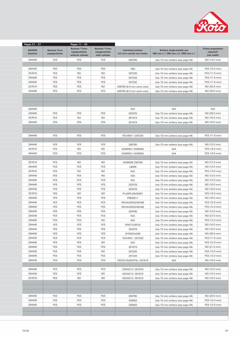
RA2000Gearbox
Backset 7mm espagnolettes
Backset 17mm espagnolettes
without cylinder
Backset 17mm espagnolettes with cylinder
Individual strikers 8.0 mm cams/5 mm hooks
Strikers single-double use600 mm x 1, 960 mm x 2, 1800 mm x 1
Frame preparationrequired?
(rail width)
294449 YES YES YES 256765 Use 10 mm strikers (see page 44) NO (14.0 mm)
294449 YES YES YES TBA Use 15 mm strikers (see page 44) YES (15.0 mm)
257616 YES NO NO 297220 Use 10 mm strikers (see page 44) YES (11.6 mm)
294449 YES YES YES 297220 Use 10 mm strikers (see page 44) YES (11.6 mm)
294449 YES YES YES 297220 Use 10 mm strikers (see page 44) YES (11.6 mm)
257616 YES YES NO 256765 (8.0 mm cams only) Use 15 mm strikers (see page 44) NO (29.5 mm)
294449 YES YES YES 256765 (8.0 mm cams only) Use 15 mm strikers (see page 44) NO (29.5 mm)
294449 N/A N/A N/A
294449 YES YES YES 203376 Use 15 mm strikers (see page 44) NO (26.0 mm)
257616 YES NO NO 261819 Use 15 mm strikers (see page 44) NO (16.0 mm)
294449 YES YES YES 261819 Use 15 mm strikers (see page 44) NO (16.0 mm)
294449 YES YES YES TECH001 / 297220 Use 10 mm strikers (see page 44) YES (11.0 mm)
294449 YES YES YES 256765 Use 10 mm strikers (see page 44) NO (12.0 mm)
257616 YES NO NO KOM003 / KOM005 N/A YES (14.5 mm)
294449 YES YES YES KOM003 / KOM005 N/A YES (14.5 mm)
257616 YES NO NO KOM008/ 256765 Use 10 mm strikers (see page 44) NO (12.0 mm)
294449 YES YES YES LB008 Use 10 mm strikers (see page 44) NO (13.0 mm)
257616 YES NO NO N/A Use 10 mm strikers (see page 44) YES (13.0 mm)
294449 YES YES NO N/A Use 10 mm strikers (see page 44) NO (13.0 mm)
294449 YES YES YES N/A Use 10 mm strikers (see page 44) NO (13.0 mm)
294449 YES YES YES 203378 Use 15 mm strikers (see page 44) NO (16.0 mm)
294449 YES YES YES 203378 Use 15 mm strikers (see page 44) NO (16.0 mm)
257616 YES NO NO PLUSPLANAG001 Use 15 mm strikers (see page 44) YES (15.0 mm)
294449 YES YES YES PREM011 Use 15 mm strikers (see page 44) NO (16.0 mm)
294449 YES YES YES REHAU020(245248) Use 10 mm strikers (see page 44) YES (12.0 mm)
294449 YES YES YES REHAU020(245248) Use 10 mm strikers (see page 44) YES (12.0 mm)
294449 YES YES YES 256765 Use 15 mm strikers (see page 44) NO (14.0 mm)
294449 YES YES YES N/A Use 15 mm strikers (see page 44) NO (27.0 mm)
294449 YES YES NO N/A Use 10 mm strikers (see page 44) YES (12.0 mm)
294449 YES YES YES SPECTUS018 Use 15 mm strikers (see page 44) NO (16.0 mm)
294449 YES YES YES 203378 Use 15 mm strikers (see page 44) NO (15.5 mm)
294449 YES YES YES SYNSEAL009 Use 15 mm strikers (see page 44) NO (28.0 mm)
294449 YES YES YES TECH001 / 297220 Use 10 mm strikers (see page 44) YES (11.0 mm)
294449 YES YES NO N/A Use 10 mm strikers (see page 44) YES (12.0 mm)
294449 YES YES YES 261819 Use 10 mm strikers (see page 44) NO (21.0 mm)
294449 YES YES NO 297220 Use 10 mm strikers (see page 44) YES (12.0 mm)
294449 YES YES YES 297220 Use 10 mm strikers (see page 44) YES (12.0 mm)
294449 YES YES YES TROC010(203375) / 261819 N/A NO (16.0 mm)
294449 YES YES YES VEKA013 / 261819 Use 15 mm strikers (see page 44) NO (15.0 mm)
294449 YES YES NO VEKA013 / 261819 Use 15 mm strikers (see page 44) NO (15.0 mm)
257616 YES NO NO VEKA013 / 261819 Use 15 mm strikers (see page 44) NO (15.0 mm)
294449 YES YES YES 256765 Use 15 mm strikers (see page 44) NO (20.0 mm)
294449 YES YES YES 328583 Use 10 mm strikers (see page 44) YES (13.0 mm)
294449 YES YES YES 328583 Use 10 mm strikers (see page 44) YES (13.0 mm)
Pages 11 – 20Pages 21 – 27

If further information is required, please contact:
Roto subsidiaries worldwide:
GermanyRoto Frank AGHeadquartersStuttgarter Straße 145–14970771 Leinfelden-EchterdingenTel +49 711 7598-0Fax +49 711 7598-253E-Mail [email protected]
The NetherlandsRoto Frank B.V.Hoofdveste 6-83992 DG HoutenTel +31 30 6385550Fax +31 30 6342840E-Mail [email protected]
SwitzerlandRoto Frank AGBernstrasse 3908953 DietikonTel +41 1 7458555Fax +41 1 7458556E-Mail [email protected]
Roto partners worldwide:
BelarusRoto Frank AGul. Woronjanskogo, 7a220039 MinskTel +375 17 2281286Fax +375 17 2281428E-Mail [email protected]
ItalySARI S.r.l.Via delle Industrie 2, no. 830020 Meolo (VE)Tel +39 0421 618211Fax +39 0421 618455E-Mail [email protected]
COMPETENCE WITHOUT BOUNDARIES
BelgiumS.A. Roto Frank N.V.Rue du Bosquet 1Zoning Industriel II1400 NivellesTel +32 67 894140Fax +32 67 841456E-Mail [email protected]
Republic of ChinaBeijing Roto Frank Building Materials Co., Ltd.Xindudongzhan, East of Xisanqi, Haidian DistrictP.C.: 100 096, BeijingTel +86 10 82950045/46Fax +86 10 82920115E-Mail [email protected]
FranceRoto Frank Ferrures S.A.S.Zone Industrielle1, rue Wilhelm Frank57380 FaulquemontTel +33 3 87292440Fax +33 3 87292444
AustriaRoto FrankEisenwarenfabrik AGLapp-Finze-Straße 218401 KalsdorfTel +43 3135 504-0Fax +43 3135 52727
PolandRoto FrankOkucia Budowlane Sp z ooWal Miedzeszynski 40203-994 WarsawTel +48 22 87216-00/-04Fax +48 22 87216-11E-Mail [email protected]
RumaniaRoto RumaniaCalea 13 Septembrie, Nr. 226Bl. V54, Sc. 1, Ap. 10, Sect.57000 BucharestTel +40 1 4114186Fax +40 1 4114186
SpainRoto Frank S.A.Pol. Industrial Molí de les PlanesParcela No. 37 B08470 Sant Celoni (Barcelona)Tel +34 93 8675720Fax +34 93 8675845E-Mail [email protected]
TurkeyRoto Frank Ltd. Sti.Alemdag Cad. Site Yolu No. 1034768 Ümraniye - IstanbulTel +90 216 412-0901 Fax +90 216 412-0903E-Mail [email protected]
HungaryRoto Elzett Vasalatkereskedelmi kft.9461 Lövö Kossuth u. 25Tel +36 99 534-100Fax +36 99 367-132E-Mail [email protected]
USARoto Frank of America, Inc.Hardware Systems & Roof Windows, Research ParkChester, CT 06412Tel +1 860 526 4996Fax +1 860 526 8390E-Mail [email protected]
ItalyTekno System S.r.l.Zona IndustrialeSS 89 Km. 9,80071011 Apricena (FG)Tel +39 0882 647671 Fax +39 0882 647669E-Mail [email protected]
Czech RepublicRoto Nové MestoKrickova ulice 37359231 Nové Mesto na MoraveTel +420 566 652411Fax +420 566 652413E-Mail [email protected]
RussiaRoto Frank AGKosmodamianskaja nab. 52, Geb. 1113054 MoscowTel +7 095 96124-27/-30Fax +7 095 96124-31E-Mail [email protected]
SloveniaRoto Loz d.o.o.Cesta 19. oktobra 521386 Stari trg pri LozuTel +386 1 7095-100Fax +386 1 7095-190
EstoniaRoto Frank Ehitusrautised OÜPeterburi tee 81-51211415 TallinnTel +372 632 6980Fax +372 632 6980E-Mail [email protected]
UkraineRoto Frank AGul. Marina Raskowoj, 17-61202002 KievTel +380 44 5595905Fax +380 44 5595905E-Mail [email protected]
GreeceEurotechnicaIndustrial area of Thessaloniki A7O.T. 18 Nr. 3457022 Sindos/P.O. Box 198Tel +30 310 796950Fax +30 310 796783E-Mail [email protected]
GermanyRoto Frank AGWerk VelbertSiemensstraße 1042551 VelbertTel +49 2051 203-1Fax +49 2051 203-251
Issu
e: O
cto
ber
20
03
R
FGB
10
6-1
©2
00
3 R
oto
Fra
nk
Ltd
W
e re
serv
e th
e ri
gh
t to
tec
hn
ical
ch
ang
es w
ith
ou
t n
oti
ce.
Roto Frank Ltd
Swift Point • Rugby • Warwickshire • CV21 1QH
Telephone: 01788 558600 • Facsimilie: 01788 558605
E-Mail: [email protected] • Internet: www.roto-frank.co.uk
WE OPEN ROOMS