Embed Size (px)
Citation preview

IOSR Journal of Electrical and Electronics Engineering (IOSR-JEEE)
e-ISSN: 2278-1676,p-ISSN: 2320-3331, Volume 8, Issue 1 (Nov. - Dec. 2013), PP 13-21 www.iosrjournals.org
www.iosrjournals.org 13 | Page
Rotor Resistance Adaptation Scheme Using Neural Learning
Algorithm for a Fuzzy Logic Based Sensorless Vector Control of
Induction Motor
Sreedev Chandran
1(Department of Electrical and Electronics Engineering, Govt. Engineering College Idukki, India)
Abstract: This paper presents the Matlab Simulation of fuzzy logic based Sensorless indirect vector control of
induction motor with a rotor resistance adaptation. Here the fuzzy controller used for speed controller offers
superior transient performance when compared with the conventional control algorithms using PI controller.
Rotor resistance of the motor will change significantly with temperature and frequency. This variation has a
major influence on the field oriented control performance of an induction motor due to the deviation of slip
frequency from the set value. This paper uses neural learning algorithm based rotor resistance adaptation
scheme for making the system robust against rotor resistance variation.
Keywords: Fuzzy Logic Controller, Indirect Field Orientation control, MRAS Approach, Neural Learning
Algorithm, Rotor Resistance estimation, Sensorless Control.
I. INTRODUCTION
Induction motors are having the advantages like high robustness, low maintenance and low cost which
makes it suitable for industrial applications. Electric drives used in industries must have fast response toward changes in torque and reference speed. Field oriented control is the best way by which high performance of
induction motor can be obtained. By using field oriented control AC motor can be controlled with same
performance level as in the case of a separately excited DC motor, in addition the motor will be having all those
advantages that an AC machine is having over DC machine [1].
In conventional field oriented control, a PI controller is used to control the speed of the induction
motor drive. The use of PI controller induces many problems like high overshoot, oscillation of speed
and torque due to sudden changes in load and external disturbances. These problems of PI controller will
affect the performance of the drive. To overcome these problems a Fuzzy Controller can be used in place of the
PI controller.
Fuzzy logic controller (FLC) is now a day is widely accepted as one of the best alternative to
conventional proportional-integral-derivative (PID) controller used in the speed control applications where high
performance is required. There are two main strengths of FLC: Firstly is that no mathematical model of the plant is needed, but knowledge of the expert is required to create a rule base. Secondly they have capability to handle
various types of nonlinearities [2]. FLC modeling incorporates certain amount of human knowledge into its
component such as fuzzy rule bases, membership functions etc. These components must be selected with an
utmost care as the selection of these components greatly influences the performance of FLC and decides the
strength of FLC.
II. VECTOR CONTROL OR FIELD ORIENTED CONTROL
The principle of Field Oriented control has been proposed by Blaschke in 1972. He proposed this as a
method to obtain DC motor performance using induction motor [1]. For the same, he has used decoupled control of torque and flux in the motor and gives its name trans-vector control. In the case of a separately
excited DC machine the field flux is perpendicular to the armature flux. Being orthogonal, these two
fluxes produce no net interaction on one another. Flux in the machine can be controlled by controlling the field
current alone and torque produced can be controlled by controlling the armature current. An AC machine is not
so simple because of the interactions between the stator and the rotor fields, whose orientations are not
held at 90 degrees but vary with the operating conditions. We can obtain DC machine-like performance in
holding a fixed and orthogonal orientation between the field and armature fields in an AC machine by
orienting the stator current with respect to the rotor flux so as to attain independently controlled flux
and torque. Such a control scheme is called flux-oriented control or vector control.
As most of the motors used in industries are cage type induction motor, Application of FOC to Cage
type induction motors is of great importance. The cage induction motor drive with vector or field oriented control offers a high level of dynamics performance and the closed-loop control associated with this
derive provides the long term stability of the system. Induction Motor drives are used in a multitude of

Rotor Resistance Adaptation Scheme Using NL Algorithm for a FL Based Sensorless VC of IM
www.iosrjournals.org 14 | Page
industrial and process control applications requiring high performances. In high-performance drive systems, the
motor speed should closely follow a specified reference trajectory regardless of any load disturbances,
parameter variations, and model uncertainties. In order to achieve high performance, field-oriented control of
induction motor (IM) drive is employed. However, the controller design of such a system plays a crucial
role in system performance.
We have the angle of the synchronous reference frame given by:
(1)
The rotor circuit equation:
(2)
(3)
In order to obtain decoupling between flux and torque the stator flux component of current ids
should be aligned on the direct axis, and the torque component of current iqs should be on the quadrature
axis, that leads to ψqr = 0 and ψdr = ψr then:
The slip frequency can be calculated as:
(4) It is found that the ideal decoupling can be achieved if the above slip angular speed command is
used for making the field orientation. The control rotor flux ψr and (dΨr/dt) =0 can be substituted in above
equation, so that rotor flux set as:
(6) The electromagnetic torque developed in the motor is given by:
(7)
The Matlab Simulink model for the simple vector control scheme with conventional control is given in Fig. 2.1.
Fig. 2.1 Matlab Simulink model of conventional FOC
III. DESIGN OF FUZZY LOGIC CONTROLLER FOR INDUCTION MOTOR DRIVES
Here we discuss a fuzzy logic controller for the Torque reference generation [3]. The first input to the
fuzzy controller is the speed error ―e‖ and second is the change in speed error ―ce‖ at the sampling time ―ts‖. The
two input variables are calculated e(ts) and ce(ts) at every sampling time as:
(8)
(9) Where , ωr*(ts) is the reference rotor speed , ωr(ts) is the actual speed, e(ts-1)is the value of error
at previous sampling time. The output of the fuzzy controller is the change in torque ΔT which is
integrated to get the reference torque as shown in the equation :
(10) The Matlab Simulink model of the fuzzy logic based controller is shown in Fig. 3.1.

Rotor Resistance Adaptation Scheme Using NL Algorithm for a FL Based Sensorless VC of IM
www.iosrjournals.org 15 | Page
Fig. 3.1 Fuzzy logic based torque reference generation.
A. Fuzzification
This is a process in which the crisp input variables to the fuzzy controller are transformed into a
normalized fuzzy set. A fuzzy set is a set containing the range of input values and an associate membership
function describing the degree of confidence of the input belonging to this range. The linguistic variables
corresponding to speed error is scaled into a common discourse universe with values between [−1, 1]. And linguistic variable corresponding to Change in speed error is scaled to a common discourse universe [-1 1].
B. Rule Base
The rule base was designed with (7x7) 49 rule of standard rule base. The linguistic terms used for input
and output variables are described below.
Fig. 3.2 membership function of the input variable e
Fig. 3.3 membership function of the input variable ce
Fig. 3.4 membership function of the output variable ΔT

Rotor Resistance Adaptation Scheme Using NL Algorithm for a FL Based Sensorless VC of IM
www.iosrjournals.org 16 | Page
Fig. 3.5 Three dimensional control surface
Table 3.1 Fuzzy Rules
C. Defuzzification
This stage introduces different methods that can be used to produce fuzzy set value for the output fuzzy
variable ΔT. Here the center of gravity or centroid of area (COA) method is used to calculate the final fuzzy
value ΔT (ts). Defuzzification using COA method means that crisp output of ΔT*(ts) is obtained by using center
of gravity, in which the crisp output ΔT(ts) variable is taken to be the geometric centre of the output fuzzy
variables value μout(ΔT)area, where μout(ΔT) is formed by taking the union of all the contributions of
rules with the degree of fulfillment greater than zero. Then the COA expression with discretized universe of
discourse can be written as:
(11)
Then Te* obtained by integration which is used to calculate i
*qs. The membership
functions defined for the input and output variables is shown in Fig. 4,5 and 6.The three
dimensional control surface is shown in the Fig 3.5. The rule base of the fuzzy controller is given in
the Table 3.1.
IV. RESULTS OBTAINED WITH FUZZY LOGIC CONTRILLER The induction motor used for the Matlab/Simulink modeling of the indirect vector control of induction motor
using fuzzy logic controller have the following specification.
Machine Rotor Resistance, Rr=2.065 ohm;
Machine rotor inductance, Llr=23.5e-3 H;
Machine stator resistance, Rs=6.7 ohm;
Machine stator inductance, Ls=23.5e-3 H; Machine mutual inductance, Lm=286e-3 H;
Machine Line Voltage, Vrms=460 v;
Machine Nominal Frequency, f=50 Hz;
Machine number of pole pairs, p=2;
Machine Inertia, I=.1 kgm2;
Machine Friction Factor, Ff=.08 Nms;
From the results obtained it is clear that the machine o/p speed traces the reference speed of very
accurately. Figure also shows the response of the system to a reference speed of 500 RPM.

Rotor Resistance Adaptation Scheme Using NL Algorithm for a FL Based Sensorless VC of IM
www.iosrjournals.org 17 | Page
Fig. 4.1 Results obtained with Fuzzy logic controller
Figure below shows the response of the system with both conventional and fuzzy logic controller. From this it
is clear that fuzzy logic controller is having good transient response when compared to conventional controller.
Fig. 4.2 Comparison of result obtained with fuzzy based and PI based controller
V. NEURAL NETWORK BASED ROTOR RESISTANCE ESTIMATION FOR SENSORLESS
CONTROL
The accuracy of speed estimation using any methods depends on the value of rotor resistance. Rotor
resistance of the machine may vary during operation due to heating of the machine. In addition, rotor resistance
can change significantly with rotor frequency due to skew/proximity effect in machines with double-cage and
deep-bar rotors. When the rotor resistance varies, there occurs an error between the actual and estimated flux
and thus there will be an error between actual and estimated torque [4].
In this paper approximations are done using multilevel feed forward network using back propagation
algorithm. Here we use simple two layered feed forward neural network trained using back propagation
algorithm for Rotor resistance estimation. In this estimator, two models of the state variable estimations can be used; one to provide the actual induction motor output states and the other to give the neural model output states
[5]. The total error between the desired and actual state variables may then be back propagated as shown in Fig.
7, to adjust the weights of the neural model, so that the output of this model tracks the actual output.

Rotor Resistance Adaptation Scheme Using NL Algorithm for a FL Based Sensorless VC of IM
www.iosrjournals.org 18 | Page
After training the neural network will behave similar to the actual machine model so that the
weights will be representing the machine parameters.
Figure 5.1 Structure of neural network system for Rr estimation
The voltage and Current model equations of the induction motor are given in Equations 11 and Equation 12:
(11)
(12) Equation 12 can also be written as :
(13) Where,
Also from Equation 13
(14) Where
Equation 14 can also be written as
(15)
Where,
Fig. 5.2 Neural network model for rotor resistance estimation
The cumulative error function E1 is given by:
(16)
The amount by which the weight to be adjusted is given by:
Rotor Resistance Adaptation Scheme Using NL Algorithm for a FL Based Sensorless VC of IM
www.iosrjournals.org 19 | Page
(17) To accelerate the convergence of the error back propagation learning algorithm, the current weight
adjustments is supplemented with a fraction of the most recent weight adjustment, as given by:
(18)
Where is the training coefficient, and is a user-selected positive momentum constant and
(19)
The change in weight W3 is given by:
(20)
So Estimated Rotor resistance:
(21)
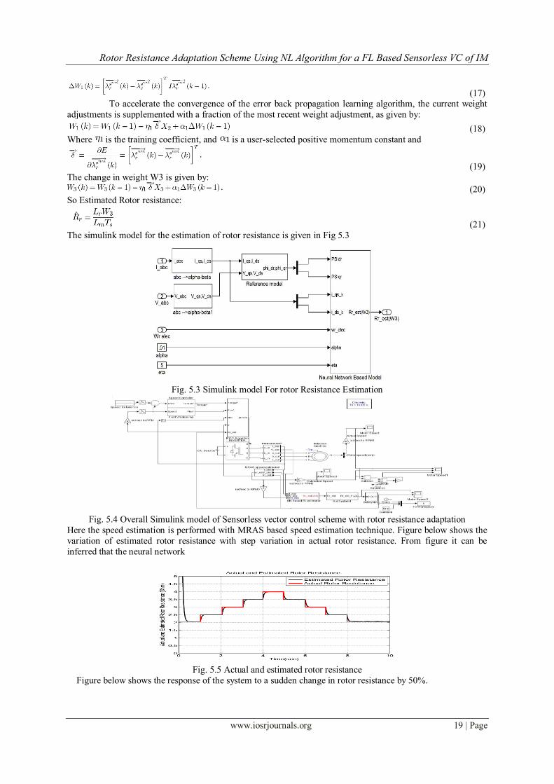
The simulink model for the estimation of rotor resistance is given in Fig 5.3
Fig. 5.3 Simulink model For rotor Resistance Estimation
Fig. 5.4 Overall Simulink model of Sensorless vector control scheme with rotor resistance adaptation
Here the speed estimation is performed with MRAS based speed estimation technique. Figure below shows the
variation of estimated rotor resistance with step variation in actual rotor resistance. From figure it can be
inferred that the neural network
Fig. 5.5 Actual and estimated rotor resistance
Figure below shows the response of the system to a sudden change in rotor resistance by 50%.

Rotor Resistance Adaptation Scheme Using NL Algorithm for a FL Based Sensorless VC of IM
www.iosrjournals.org 20 | Page
Fig. 5.5 Response of the system with to 50% variation in rotor resistance
Figure below shows the response of the system to a sudden change in rotor resistance by 100%.

Rotor Resistance Adaptation Scheme Using NL Algorithm for a FL Based Sensorless VC of IM
www.iosrjournals.org 21 | Page
Fig. 5.6 Response of the system to 100 % variation in rotor resistance
It can be seen that even at the instant of rotor resistance variation; the change in rotor speed is very small and
can be neglected. So we can say that the implemented scheme for rotor resistance estimation is capable of
making the system robust against rotor resistance variation.
VI. CONCLUSION
The performance of a Fuzzy logic Based speed controller for indirect vector control of induction motor
is been verified. Simulation results shows that Fuzzy based speed controller posses better Dynamic performance
towards sudden changes. Also it posses very low settling time and zero peak overshoot. The neural network
based rotor resistance estimation seems to well tracking the actual rotor resistance, and Rotor resistance adapted
system modeled seems to be robust to any rotor resistance variation.
REFERENCES
Books: [1] Bimal K Bose,‟ Modern Power Electronics and AC Drives‟, Third edition, INDIA: Pearson Education, Inc., 2007. Journal Papers:
[2] Birachi Narayan Kar, K B Mohanty, „Indirect Vector Control of Induction Motor Using Fuzzy logic Controller‟, IEEE 2011.
[3] Iulian Birou , Virgril Maier, Sorin Pavel, Calin Rusu, ―Indirect Vector Control of an Induction Motor with Fuzzy Logic based
Speed Controller‟; Advances in Electrical and Computer Engineering, Volume 10 Number 1, 2010.
[4] B. K. Bose, ―Neural network applications in power electronics and motor drives—An introduction and perspectives,‖ IEEE Trans.
Ind.Electron., vol. 54, no. 1, pp. 14–33, Jan. 2007.
[5] C. Schauder, ―Adaptive speed identification for vector control of in-duction motors without rotational transducers,‖ IEEE Trans. Ind.
Appl.,vol. 28, no. 5, pp. 1054–1061, Sep./Oct. 1992..
[6] Baburaj Karanayil, Member, IEEE, Muhammed Fazlur Rahman, Senior Member, IEEE, and Colin Grantham-― Online Stator and
Rotor Resistance Estimation Scheme Using Artificial Neural Networks for Vector Controlled Speed Sensorless Induction Motor
Drive‖ IEEE transactions on industrial electronics, vol. 54, no. 1, February 2007.