Embed Size (px)
Citation preview
NASA Technical Memorandum 84298
(NASA-TH-84298) R I;OTOR TFCHNOLOGY N83- 18712 ASSISSNENT OF THE A D V A N C I N G P L A D E CCNCEPT (NASA) 60 p HC R39/PlF A 9 1 CSCL 01C
Unclas G3/05 02941
A Rotor Technology Ass~ssment of the Advancing Blade Concept William A. Pleasants
January 1983
Natonal Aeronaut~cs and Space Arlrn~ri~straiion
AVRADCCd Technical Report 82-A-18
Un~ted States Army Av~atlon Research and Development Cornrnand
https://ntrs.nasa.gov/search.jsp?R=19830010441 2020-04-24T00:48:53+00:00Z
NASA Technical Memorandum 84298 AVRADCOM Technical Report 82-A-18
A Rotor Technology Assessment of the Advancing Blade Concept William A. Pleasants, Applied Technology Laboratory
AVRADCOV Research and Technology Laboratories Ames Research Center, Moffett Field, California
Nat~onal Acronaut~c.~ and Soace Atlm:nistratlon
bnlted States Army Av~at~on Research and Development Command St Louis. Mlssolm 631 66
Ames Research Center Moffett Fltld Cal~fnrn~a 94035
A ROTOR TECHNOLOGY ASSESSMENT OF THE ADVANCING BLADE CONCEPT
William A'. P l e a s a n t e
U.S. Army A p p l i e d Technology L a b o r a t o r y (AVRADCOM), Ames R e s e a r c h C e n t e r
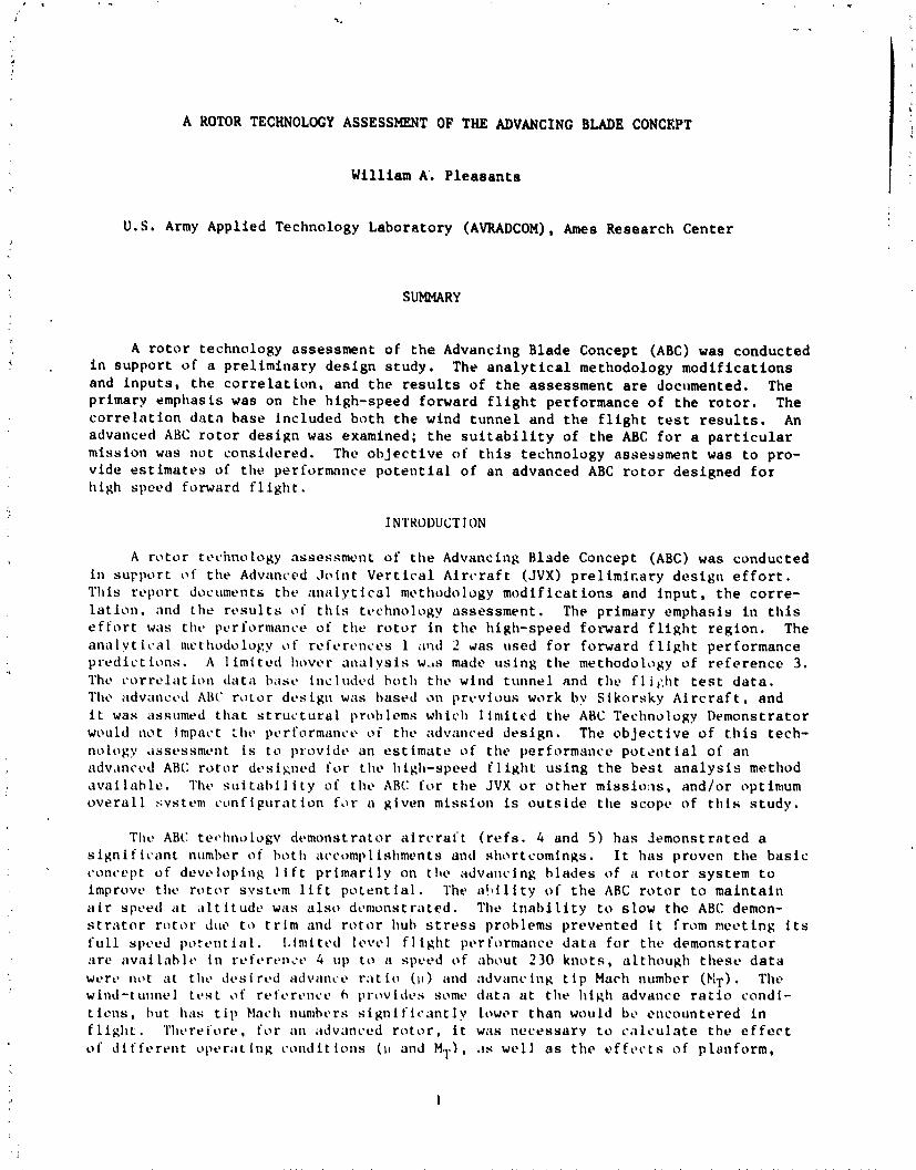
SUMMARY
A r o t o r t e c h n o l o g y m s e s s m e n t o f t h e Advancing Blade Concept (ABC) was c o n d u c t e d i n s u p p o r t o f a p r e l i m i n a r y d e s i g n s t u d y . The a n a l y t i c a l methodology m o d i f i c a t i o n s and i n p u t s , t h e c o r r e l a t i o n , and t h e r e s u l t s o f t h e a s s e s s m e n t are documented. The p r i m a r y e m p h a s i s was on t h e h igh-speed f o r w a r d f l i g h t p e r f o r m a n c e o f t h e r o t o r . The c o r r e l e t i o n d a t a b a s e i n c l u d e d b o t h t h e wind t u n n e l and t h e f l i g h t tes t r e s u l t s . An advanced ABC r o t o r d e s i g n was examined ; t h e s u i t a b i l i t y o f t h e ABC f o r a p a r t i c u l a r m i s s i o n was n o t c o n s i d e r e d . The o b j e c t i v e o f t h i s t e c h n o l o g y a s s e s s m e n t was t o pro- v i d e e s t i m a t e s of t h e per formance p o t e n t i a l o f a n advanced ABC r o t o r d e s i g n e d f o r h i g h s p e e d f o r w a r d f l i g h t .
INTRODUCTION
A r o t o r t c h w l o g y a s s e s s m e n t o f t h e Advancing Blade Concept (ABC) was c o n d u c t e d i n s u p p o r t o f t h e Advanced J o i n t V e r t i c a l A i r c r a f t (JVX) p r e l i m i r . a r y d e s i g n e f f o r t . T h i s r e p o r t documents tht. i ~ n i ~ l y t i c o l mt~t l lodology modif i c e t i o n s and i n p u t , t h e c o r r e - l a t i o n . and t h e r e s u l t s o f t h i s t v c h n o l o g y u s s e s s m e n t . The p r i m a r y e m p h a s i s i n t h i s e f f o r t was tilt' performance of t h e r o t o r i n t h e h igh-speed f o t w a r d f l i g h t r e g i o n . The a n a l v t it.81 nwtlludo1ol:y o f r e f r ~ r t ~ n c c s 1 ;rlld 2 Gas used f o r f o r w a r d f l i g h t p e r f o r m a n c e p r e d i c t i o n s . A 1 i m i t e d I ~ o v ~ r a n a l v s i s w-AS made u s i n g t h e methodology of r e f e r e n c e 3. The c c j r r c l a t i o n tieti\ h i~s t . included hot11 t h c wind t u n n e l and t h e f l i , : h t test d a t a . Tho i idvancc~~l AB(: r o t o r d t > s i g u was based o n p r c v i o u s work by S i k o r s k y A i r c r a f t , and i t was ~ s s u n l e d t h a t s t r u c t u r a l p rob lems which 1 imi t c d t h e ABC Technology D e m o n s t r a t o r would n o t Inlpat.t ;htl pt!rfirrmimc.c o i t h v : ~ d v a n c e d d e s i g n . The o b j e c t i v e o f t h i s t e c h - no logy .i:;st>ssmclnt is t o providt. an e s t i m a t e u f t h e p e r f o r m a n c e p o t z n t i a l o f a n adv,inced AHC r o t o r d1.s i s n r d f o r t hc h igh-speed f 1 i g h t u s i n g t h e b e s t a n a l y s i s method a v a i l a h l e . 'I'ht- s u i t ~ i b i l i t y of tllc. ABC f o r t h e J V X o r o t h e r m i s s i o n s , s n d l o r optimum o v e r a l l svstcnl ~ ~ o n f i p u r a t i o n f ~ r r u g i v e n m i s s i o n is o u t s i d e t h e s c o p c of t h i s s t u d y .
Tht? ABC t e c h n o logv dt.monst r a t o r e i r c r a i t ( r e f s . 4 and 5 ) h a s demonst r a t e d a s i g n i f i c a n t nnmber of t)ot h a c ~ r ~ ) m p l i s h m c n t s and s l ~ o r t c o m i n g s . I t h a s p roven the b a s i c ~.onc-cpt o f d e v e l o p i n g l i f t p r i m a r i l y on t l w ~ i d v d n c i n g b l a d e s of ii r o t o r s y s t e m t o improvc t h e r o t o r s y s t v m l i f t p o t e n t i a l . 'The a ! b i l i t y o f t h e ABC r o t o r t o m a i n t a i n 11ir spc.ed a t ; i l t i t u d c w i t s i l l s o d t m u n s t r a t e d . l'llcb i n a b i l i t y t o s l o w t h e ABC demon- s t r a t o r r o t o r LIW t o t r i m and r o t o r huh s t ress prob lems p r e v e n t e d i t f rom n c c t t n g i t s f u l l spcaed po:c~nt l o l . Limi t c d I c v i ~ l f l i g h t pt~rformclncc d a t a f o r t h e demonst r a t o r a r c ctvni l a h l c i n r c ~ f v r t ~ n ~ ~ t \ 4 up t o 11 specad of ohout 230 kncrts , a l t h o u g h t h e s e d a t a W L - ~ L ~ no t a t tht. d c ~ s i red tidvant.~. r i \ t i o (11 iind 11Jvt1nc in^ t i p Mach number (PIT) . The wind-t u ~ l u e l t v s t o f r t ~ i c . r l ~ n ~ - i ~ C, pr tw I & ~ s some d a t n a t t h e h i g h ~ d v a n c e r a t i o c o n d i - t icms, hu t h a s t i p Nat.h numhcrs s i g n i f i c m t 1 y l c r w p r t h a n would brb encountered i n f l i g h t . 'l ' llc~rei'orr, f o r nn ;~dvanc.ed r o t o r , i t was n e c e s s a r y t o c i ~ l ~ u l n t e t h e e f f e c t o f d i f f c r t a n t oper i l t t n g c o n d i t i o n s 01 end MI.), ,IS w e l l a s t h e e f f e c t s o f p l a n f o r m ,
t w i s t , t a p e r and a i r f o i l s . The b a . i c approach taken was t o c o r r e l a t e w i t h t h e e x i s t i n g f l i g h t and wind tunne l t e s t d a t a and then t o p r e d i c t t h e performance of a given advanced des ign. S i g n i f i c a n t l i m i t a t i o n s were encountered wi th a l l of t h e e x i s t i n g d a t a which reduced conf idence i n both t h e exper imenta l and t h e a n a l y t i c a l r e s u l t s . The performance increments were c a l c u l a t e d f o r t h e primary d e s i g n v a r i a b l e s (opera t ing c o n d i t i o n s , t w i s t , a i r f o i l s , e t c . ) .
Ana ly t i ca l Me thodology
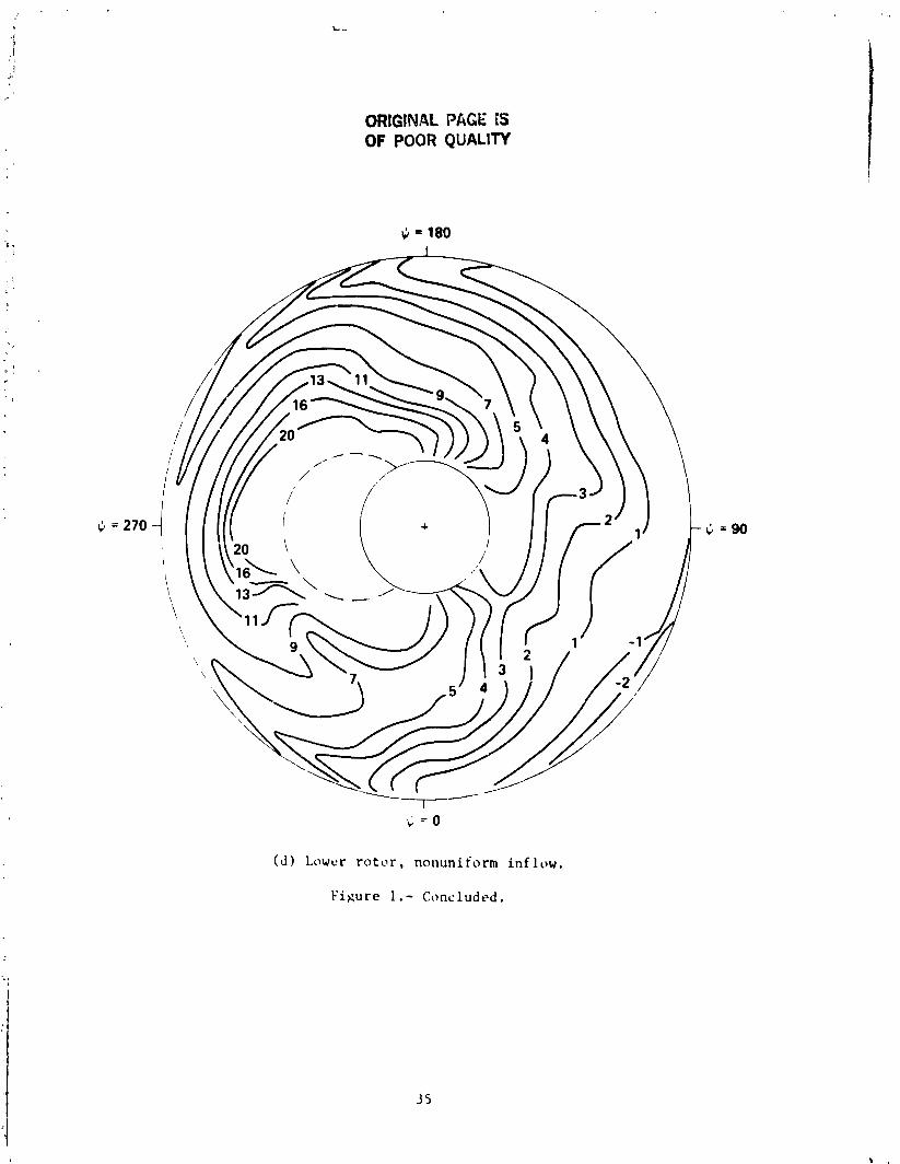
The comprehensive h e l i c o p t e r a n a l y s i s of r e f e r e n c e 2 was modified t o t r e a t t h e ARC r o t o r . I n t h e modified code, t h e ABC r e p l a c e s t h e tandem r o t o r c o n f i g u r e t i o n . The program modi f i ca t ions w e n not e x t e n s i v e and were requ i red f o r only t h r e e sub- r o u t i n e s which a r e g iven i n appendix A. The ABC c o n t r o l laws given i n r e f e r e n c e s 4 and 5 may be represen ted i n t h e a n a l y s i s by r e d e f i n i t i o n of i n p u t q u a n t i t i e s a s shown i n Appendix B. The modified a n a l y s i s is r e s t r i c t e d i n t r i m o p t i o n s t o t h e f ree - f l i g h t trim c a s e s ( s e e r e f . 2 , volume 2 , page 37). The major advantage of t h e analy- sis is its a b i l i t y t o model t h e c o a x i a l r o t o r r e a l i s t i c a l l y and t h u s a l l o w computa- t i o n of t h e r o t o r - r o t o r i n t e r f e r e n c e . Previous a n a l y s i s of t h e ABC r o t o r was basel! on it s i n g l e r o t o r a n a l y s i s which represen ted t h e ABC r o t o r a s a s i n g l e r o t o r with a l l b lades i n one plane and trimmed wi th a l i f t o f f s e t . The p r e s e n t a n a l y s i s i s capable of r ep resen t tng two r o t o r s i n c l o s e proximity wi th f u l l wake i n t e r a c t i o n . Thc r o t o r - r o t o r i n t c r f c r e n c e s i g n i f i c a n t s h i f t s i n t h e r o t o r ang le of a t t a c k a s shown i n f i g u r c 1. Calc.ulatcd r o t o r l i f t - t o - d r a g r a t i o (LID,) f o r t h e uniform inflow por t ion o f t h e an; l lys is was s i g n i f i c n n t ly more o p t i m i s t i c than t h e nonuniform inflow r e s u l t s . Comparison f o r the advanced des ign of nonuniform and uniform in f low r t l su l t s wi th tlw r e s u l t s c r f r e f e r e n c e s 7 and 8 a r e shown l a t e r i n t h i s paper.
CORRELATION
Kotor Conf i g u r a t ton
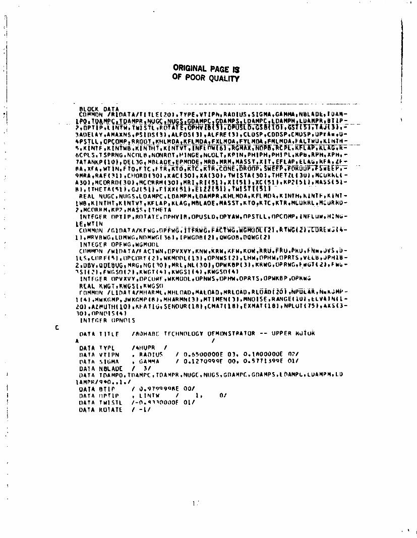
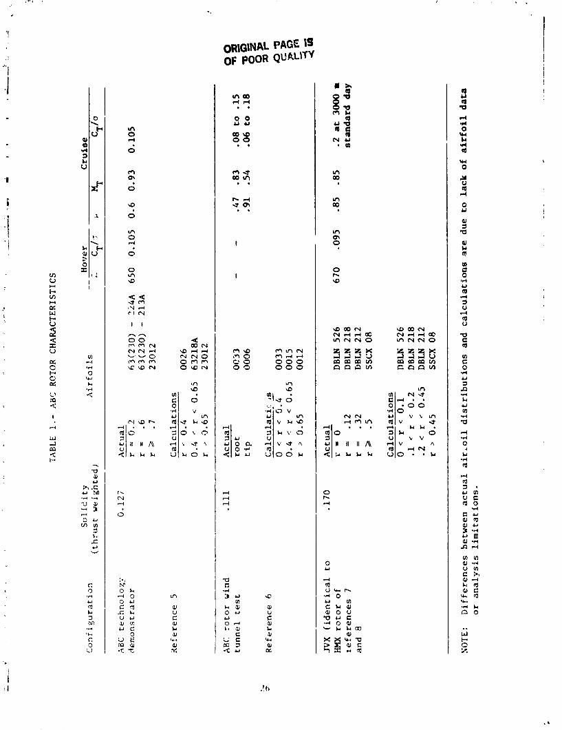
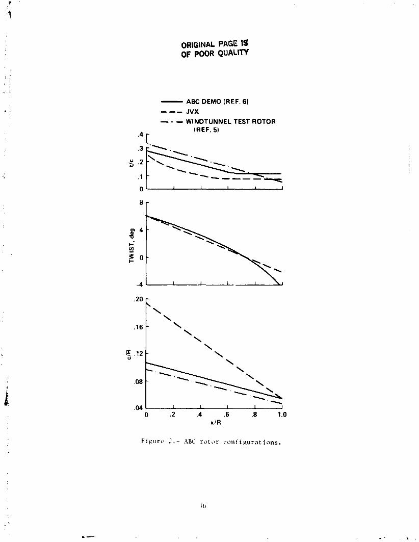
T h r w AH(: r o t o r c o n i i g u r a t ions were considered i n making t h e ABC technology pro- j c c t i o u s . (Thc ABC f l i g h t t e s t is desc r ibed in r e f s . 4 and 5. T h e e a r l i e r ABC wind tunnel t c s t d:ltir a r c presented i n r e f . 6 . ) Due t o t h e l i m i t e d time a v a i l a b l e , the t1MS r l \ t i rr &>sign o f r e fe rences 7 and 8 was s e l e c t e d a s the b a s i c c o n f i g u r a t i o n f o r .lu ;ldvilnccd A H C design. The desitjn g o a l s and t h e o p e r a t i n g c o n d i t i o n s f o r t h e J V X r o t o r were. ~ w ; ~ r l v i d t w t i z a l t o t h e H E N r o t o r , and s ign i f i c . an t changes i n t h e p e r f o r - mance t r ends due t o mnJor r o t o r dcs ign vciriablcs ( t w i s t , t a p e r , a i r f o i l s ) were not expected. I'hc c.hurd, thc. thic.knt>sscs, and tht. t w i s t d i s t r i b u t i o n s of t h e t h r e e r i \ t ~ i r s used in making thcs tcc l~nologv p r o j e c t i o n s a r e shown i n f i g u r e 2 wi th nddi- tion.ll ~ . l ~ ; l r : i c t t ~ r i s t i ~ . s )!iven i n table 1. Thc a i r i c i i l dilta used i n a n a l y s i s of the r o ~ ~ , r s were prnpr ie t r i rv t o Sikorsky A i r c r a f t , but a r e desc r ibed i n genera l terms i n re i t - rcncc 7. With tht* tasl.c.pt i o n of t h e a i r f t r i l d a t a , t h e input r equ i red by the ~ . o t ~ ~ p u t t ~ r an; l lybis is f u l l v providcd hy t h e block d a t a r o u t i n e s l i s t c d i n Appendix C.
. . Ilrcl ~ . o r r c ~ l . , , ion r.1 i o r t s wi tll t h e hBC demcrnstrator a i r c r a f t r e f l e c t t h e l i m i t a -
t ions t llc' ct lrrcnt l y .iv;lt l ah le ciat;l. No dcd ica t ed performance t e s t i n g was con- d u ~ . t c ~ d f o r thc A R C dt~mcinst r . ~ t o r i n chc- .tusi 1 i .lry propuls ion mode. Thc high-speed p t~r I '~~r l i i ; ln~ .~* .11id the' t r im (1at.1 (stat' f i g s . I 3 h and 1$7 c) f r e f . 4 ) c s h l b i t s i g n i f i c a n t
OKIGIldriL PAC;; IS OF POOR QUALITY
s c a t t e r due t o t h e v a r i a t i o n i n t h e c o n t r o l t r i m p o s i t i o n s ( A , B i , b e t , l'), t h e c o l l e c t i v e p o s i t i o n , and t h e r o t o r speed. The v a r i a t i o n s !.n a i r c r a f t a t t i t u d e and, hence f u s e l a g e l i f t and drag, f u r t h e r complicate c o r r e l a t i o n . The l i m i t a t i o n s on t h e a v a i l a b l e a i r f o i l d a t a and t h e a b i l i t y of t h e a n a l y s i s t o r e p r e s e n t t h e a i r f o i l d i s t r i b u t i o n a s r e f l e c t e d i n t a b l e 1 were a d d i t i o n a l causes f o r concern,
The l i f t and drag c h a r a c t e r i s t i c s f o r t h e ABC demonstra tor a r e a v a i l a b l e i n re fe rences 9 and 10. The d rag d a t a f o r t h e ABC demonstrator and t h e r e l a t e d hub f drag s c a l i n g r e l a t i o n s a r e p resen ted i n Appendix D. The f u s e l a g e aerodynadics char- a c t e r i s t i c s conta ined i n t h e block d a t a r o u t i n e f o r t h e ABC were taken from r e f e r - I ence 9. The measurements of a u x i l i a r y t h r u s t , combined w i t h t h e wind tunne l measure- ment of a i r c r a f t drag, i n d i c a t e a r o t o r d rag equ iva len t t o about 1.16m2 (12.5 f t 2 ) a t 230 knots.
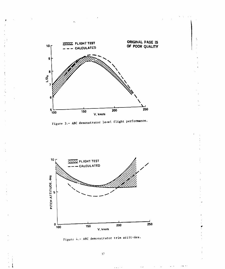
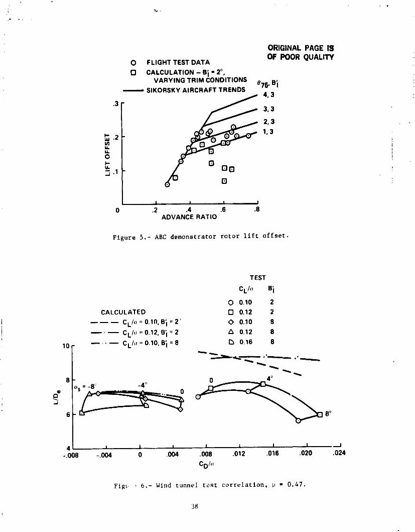
Figure 3 compares t h e r o t o r f l i g h t test performance wi th t h e c a l c u l a t e d r e s u l t s . The t r i m a t t i t u d e is compared i n f i g u r e 4. The f l i g h t t e s t d a t a a r e presented a s a crosshatched region t o i n d i c a t e t h e u n c e r t a i n t y i n t h e d a t a . The c a l c u l a t e d t r i m a t t i t u d e (and t o a l e s s e r e x t e n t LIDe) is 1 . l f luenced by t h e es t imated r o t o r drag. For t h e a n a l y s i s , t h e d i f f e r e n t i a l l o n g i t u d i n a l and l a t e r a l c o n t r o l ang les were f i x e d a t 0' t o 2', r e s p e c t i v e l y , and t h e phase ang le w a s f i x e d a t 40'. The a n a l y s i s was s e t t o conduct a 6-degree-of-freedom t r i m t o determine t h e c o l l e c t i v e , t h e d i f - f e r e n t i a l c o l l e c t i v e , t h e l o n g i t u d i n a l and l a t e r a l c y c l i c , t h e p i t c h a t t i t u d e , and t h e r o l l a t t i t u d e . The c o r r e l a t i o n wi th t h e f l i g h t t e s t could have been improved i n the 160- t o 210-knot region w i t h a d d i t i o n a l refinement of t h e e s t i m a t e of t h e r o t o r drag. Due t o t h e l a r g e u n c e r t a i n t y i n r o t o r d rag e s t i m a t e s and t h e l i m i t e d time a v a i l a b l e , t h i s a d d i t i o n a l e f f o r ~ was no t considered worthwhile a t t h e p resen t time.
The l i f t o f f s e t f o r t h e f l i g h t t e s t d a t a is compared t o t h e c a l c u l a t e d va lues i n f i g u r e 5. The l a r g e v a r i a t i o n s i n the c a l c u l a t e d l i f t o f f s e t a t a g iven advance r a t i o a r e due t o t h e s i g n i f i c a n t l y varying t r i m cond i t ions obta ined when i n v e s t i g a t - ing t h e e f f e c t s of t h e a u x i l i a r y propuls ive f o r c e and p i t c h a t t i t u d e . The low v a l u e s of t h e l i f t o f f s e t a t high advance r a t i o appear t o be due i n l a r g e p a r t t o t h e t r i m cond i t ion c a l c u l a t e d . A t u 0.6 and l i f t o f f s e t x/R = 0.106, t h e c o l l e c t i v e p i t c h was approximately 8 7 5 = -lo. The reduc t ion i n t h e l i f t o f f s e t wi th reduced 8 7 5 appears c o n s i s t e n t wi th t h e Sikorsky a i r c r a f t t r e n d s shown i n f i g u r e 5.
ABC Wind Tunnel Tes t
The wind tunne l t e s t of r e fe rence 6 was used t o ga in i n s i g h t i n t o the a b i l i t y of t h e a n a l y s i s t o p r e d i c t t h e e f f e c t s of h igh advance r a t i o and t o c a l c u l a t e t h e l i f t o f f s e t . A s can be seen i n t a b l e 1, t h e combination of f l i g h t and wind tunnel t e s t d a t a s t i l l f a l l s s h o r t of cover ing t h e advance r a t i o s and t h e t i p Mach number d e s i r e d f o r t h e advanced design. The wind tunnel t e s t d a t a does provide a wide range of p ,
CL/a, B; , a s , and CD/a cond i t ions .
Table 1 shows t h e a i r f o i l s e c t i o n s used i n r e p r e s e n t i n g t h i s r o t o r . A consider- a b l e d i f f e r e n c e e x i s t s between t h e a c t u a l a i r f o i l d i s t r i b u t i o n and t h a t used i n ca l - c u l a t i o n , but i t was thought t h a t genera l t r e n d s would not be g r e a t l y a f f e c t e d . A 3-degree-of-freedom trim was used t o t r i m input zL/a and CD/o. Trim t o a given s h a f t angle was forced through input of a l a r g e value of fuse lage M,/q. The r o t o r c o n t r o l s e t t i n g s f o r A;, A O t , and r were not recorded i n re fe rence 6 and were taken t o be zero .
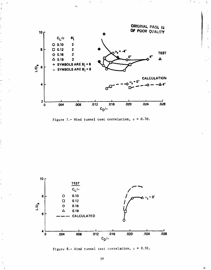
Figures 6 t o 8 p r e s e n t t h e exper imenta l d a t a f o r r o t o r LIDe and t h e c o r r e l a - t i o n ob ta ined . P r e d i c t e d L/D,'S a t 0.47 and 0 .91 were somewhat o p t i m i s t i c compared t o t e s t d a t a . A t an advance r a t i o of 0 .7 , t h e p r e d i c t e d LIDe was s i g n i f i c a n t l y '
worse than t h e t e s t . A d e t a i l e d i n v e s t i g a t i o n of t h e r e s u l t s i n d i c a t e d s i g n i f i c a n t s t a l l , and t h e v a l i d i t y of t h e computat ional r e s u l t s f o r t h i s c a s e was open t o ques t ion . The use o f uniform v e r s u s nonuniform in f low o r of dynamic s ta l l models d i d no t a f f e c t t h e b a s i c r e s u l t a t 0.7 advance r a t i o .
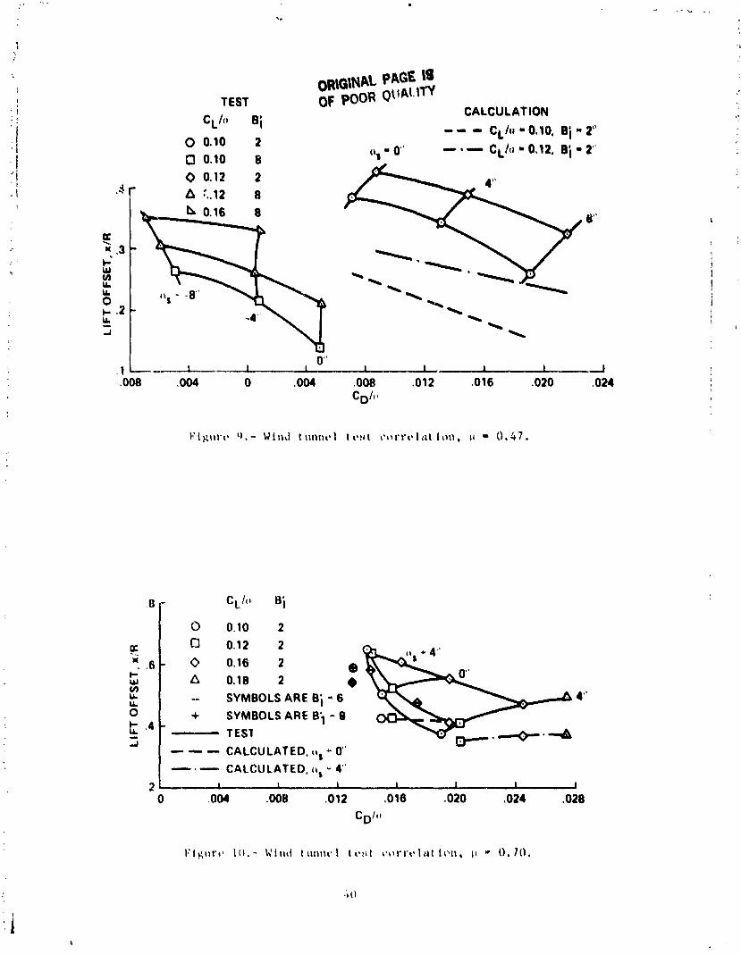
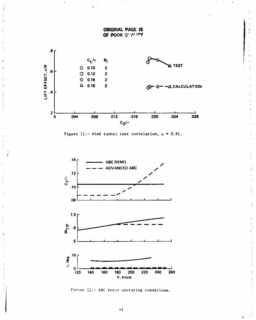
The l i f t o f f s e t d a t a from t h e wind t u n n e l t e s t were of p a r t i c u l a r i n t e r e s t a s t h e r o t o r s h a f t angle , t h e l i f t , and t h e t h r u s t were w e l l de f ined . P o s s i b l e v a r i a - t i o n s i n t h e s e q u a n t i t i e s f o r t h e f l i g h t test d a t a caused cons ide rab le s c a t t e r i n t h e c a l c u l a t e d r e s u l t s . F igures 9 t o 11 p r e s e n t t h e l i f t o f f s e t d a t a f o r bo th theory and experiment. The a n a l y s i s s i g n i f i c a n t l y underpredic ted t h e magnitude of t h e l!€t o f f s e t f o r a l l cases . The d i f f e r e n c e s i n theory and experiment a r e m i t i - ga ted , i n p a r t , by t h e approximations made i n inpu t t o t h e a n a l y s i s f o r t h i s config- u r a t i o n . Also, no te t h e t r e n d f o r dec reas ing e f f e c t i v e n e s s i n B; f o r reducing t h e l i f t o f f s L t a s advance r a t i o i n c r e a s e s .
ABC Advanced Design
A s s t a t e d e a r l i e r , t h e advanced ABC c o n f i g u r a t i o n was based h e a v i l y on t h e r e s u l t s of r e f e r e n c e s 7 and 8. These r e f e r e n c e s i n d i c a t e t h a t ve ry l a r g e improve- ments i n r o t o r LIDe a r e p o s s i b l e a s compared t o those demonstrated by t h e f l i g h t t e s t program. The performance e s t i m a t e s f o r t h e advanced des ign which fo l lows a r e based on both the demonstrated c a p a b i l i t y achieved i n f l i g h t t e s t , and on assumed s o l u t i o n s t o problems encountered by the demonstrated a i r c r a f t .
The g e n e r a l requirements f o r t h e advanced des ign were t h a t i t have a maximum speed c a p a b i l i t y of 250 knots a t a l t i t u d e s up t o 3000 m (10,000 f t . ) , wi th hover performance a t t h e des ign p o i n t approximately e q u a l t o t h e f l i g h t t e s t a i r c r a f t . The o v e r a l l t r e n d s of t h e maximum blade load ing and t h e f l i g h t envelope would be s i m i l a r t o those shown f o r t h e demonstra tor a i r c r a f t ( s e e f i g s . 3 and 6 of r e f . 5 ) . The advanced r o t o r c r u i s e $10 was chosen t o f a l l w i t h i n t h e c a p a b i l i t y demon- s t r a t e d by t h e ABC a i r c r a f t f l i g h t t e s t . The r o t o r does not have t h e c a p a b i l i t y t o hold performance up t o t h e 7,500-9,000 m range d e s i r e d f o r some JVX miss ions . A s i g n i f i c a n t l y inc reased r o t o r s o l i d i t y o r t h e a d d i t i o n of a wing would be requ i red t o meet the h igher a l t i t u d e cases .
A l a r g ? p o r t i o n of t h e p red ic ted performance improvement of t h e new ABC d e s i g n is due t o t h e more optimum o p e r a t i n g c o n d i t i o n s . A t y p i c a l d i f f e r e n c e i n b lade load ing , p i t c h a t t i t u d e and t i p Mach number between t h e demonstra tor a i r c r a f t r o t o r and t h e advanced r o t o r a r e shown i n f i g u r e 12. To meet t h e s e o p e r a t i n g c o n d i t i o n s , i t is necessary t o s i g n i f i c a n t l y reduce t h e r o t o r RPM. The r o t o r hub and a i r c r a f t s t r e s s problems prevented t h e ABC demonstra tor a i r c r a f t from o p e r a t i n g a t t h e d e s i r e d c o n d i t i o n s . The improved s t r u c t u r a l des ign and r e v i s e d a i r c r a f t t r i m o f f e r one means o f c o n t r o l l i n g t h e r o t o r RPM. Di rec t l i n k i n g of t h e r o t o r and t h e a u x i l i a r y propul- s i o n d r i v e system o f f e r s ano the r approach. For t h e purposes of t h i s s tudy , i t was simply assumed t h a t an adequate mechanism fo r RPM c o n t ~ o l would be a v a i l a b l e . The a i r f o i l s were s e l e c t e d t o a l low o p e r a t i o n a t t i p Mach numbers up t o 0.85. The advance r a t i o ranged from about 0.47 a t maximum range speed t o about 0.85 a t maximum c r u i s e speed. The s p e c i f i c v a l u e s a r e , of course , dependent on t h e g iven des ign and miss ion requirements .
The computer analysis was run in two modes. The initial runs were made using the ABC demonstrator airframe aerodynamics and a full 6-degree-of-freedom trim. This resulted in the trim attitude (0° to lo) shown in figure 12. The fuselage aerodynam- ics were also modified to force the rotor to trim at a given attitude, as was done in the wind tunnel correlation. In both caees, the differential cyclic and phase angle were identical to that used for the ABC demonstrator aircraft correlation. The auxiliary thrust was chosen to put the rotor at or near autorotation. The final results shown are for the nonuniform inflow case, although some uniform inflow results are shown for comparison with the data of references 7 and 8.
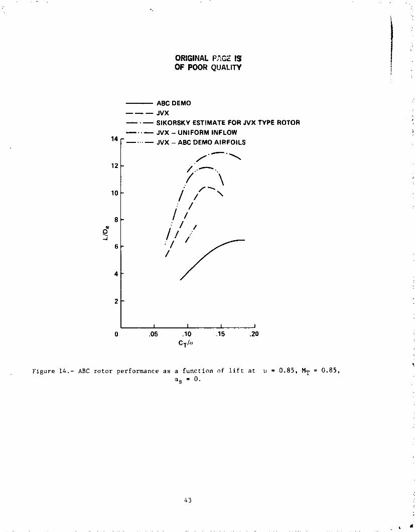
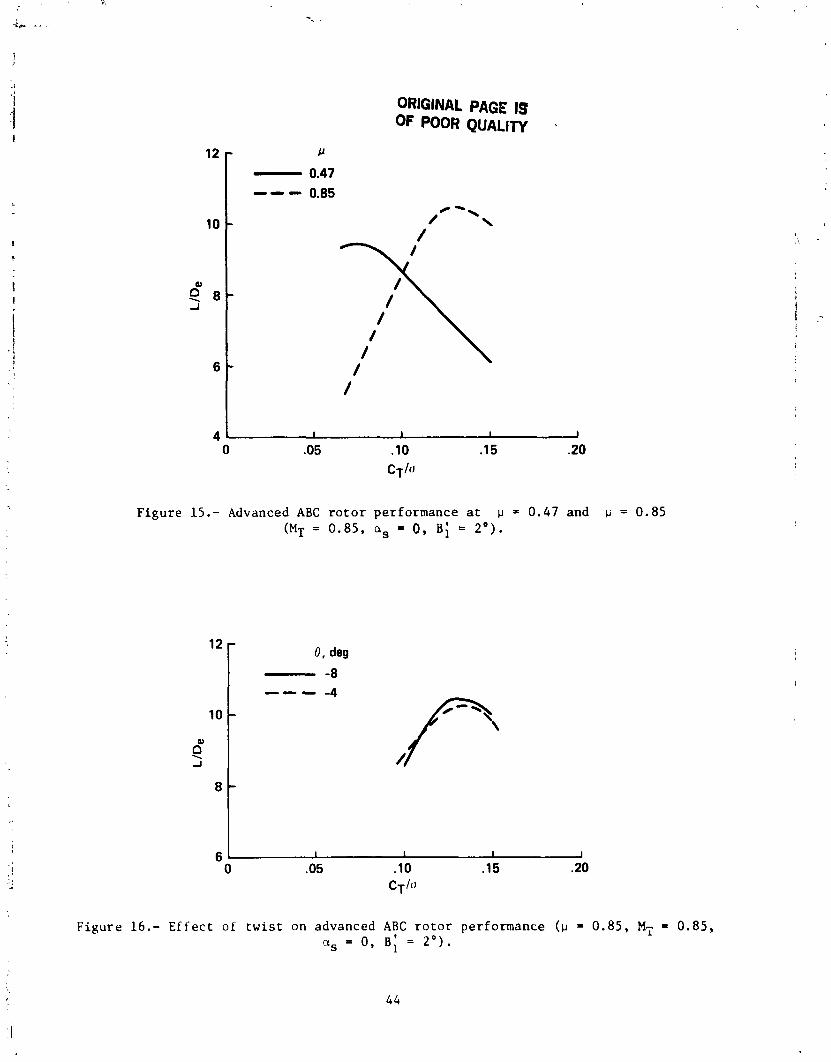
Th@ results of the performance calculations presented in figures 13-16 generally substantiate that greatly improved performance is obtainable for the ABC although the present estimates are not as great as those in references 7 and 8. Figures 13 and 14 summarize the rotor performance calculations. The calculated improvement in LIDe between the ABC demonstrator rotor and the JVX advanced rotor design is due about equally to optimum operating conditions, planform, and twist improvements. The rotor-rotor interference as indicated by the difference between uniform and nonuni- form inflow calculations showed a significant impact for all cases investigated. The rotor L/Dets for several advanced ratios expected to be typical of JVX missions are shown in figure 15. Note that the design CT/a has been chosen to provide maximum L/D, at normal cruise conditions, and failure to trim the rotor at the design RPM could significantly reduce rotor LIDe. Also note that LIDe peaks much sooner for the advanced design compared to the demonstrator. This is expected as the outer 502 of the advanced blade uses an airfoil section with significantly lower maximum lift capability than the demonstrator.
The rotor twist, particularly in the tip region, has been significantly reduced for improved high speed performance. The ABC demonstrator flight test results and subsequent calculations indicate significant regions of negative lift on the rotor at high speed. The twist selected generally eliminated these regions. The addi- tional reductions in twist had no benefit in forward flight as shown in figure 16, and would have an adverse impact on hover performance.
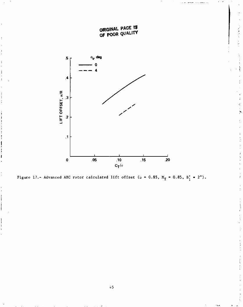
The determination of the lift offset has a strong impact on the structural design of the ABC rotor. For the purposes of the JVX preliminary design studies which this effort supported, a lift offset of 32% was assumed. The present inves- tigation was limited to the determination of the lift offset for a limited number of cases typical of the expected operating conditions. The differential lateral cyclic was held fixed at the same vslue ( i s ) used for the ABC flight test correlation. Figure 17 shows the calculated lift offset at shaft angles of 0' and 4 ' . In this case, the rotor LIDe was not significantly affected by the modified trim condition although the lift offset was strongly affected. This general trend is in agreement with the wind tunnel test data presented earlier. The impact of increased B! was not calculated although it would also reduce the lift offset. Although the eirlier correlation presented indicated that the analysis tended to underpredict the lift offset, the combination of trim attitude and increased B; should provide an adequate margin to keep the flight lift offset at or below the assumed design value of 0 . 3 2 .
Hover Performance
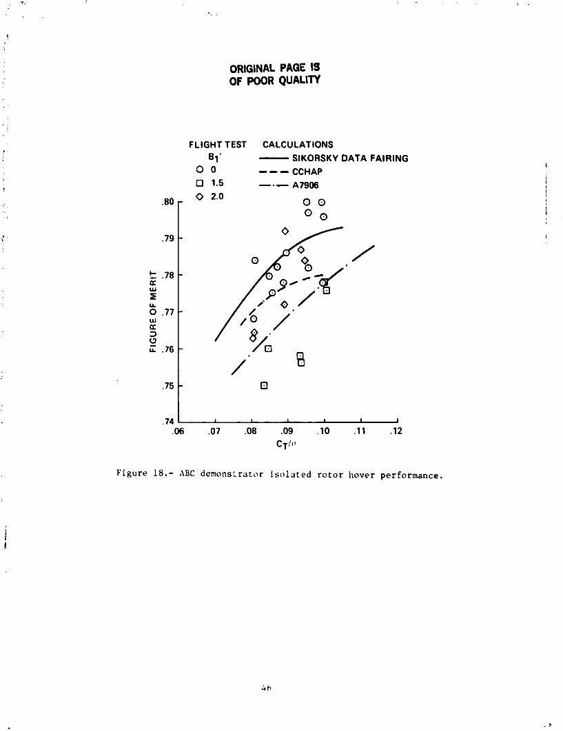
The hover performance of an ABC rotar for the JVX missions was viewed as less important than the high speed cruise performance. The airfoils and twist were selected for cruise performance. The very limited data available for correlation in
hover, and t h e l e s s e r importance of hover i n t h i s des ign s tudy , d i c t a t e d a s imple r a n a l y t i c a l approach f o r hover performance. Hover performance c a l c u l a t i o n s f o r t h e Sikorsky CCHAP code may be e x t r a c t e d from r e f e r e n c e This code is desc r ibed b r i e f l y i n r e f e r e n c e 11. Addi t iona l c a l c u l a t i o n s were made us ing t h e B e l l A7906 code desc r ibed i n r e f e r e n c e 3. Both of t h e a n a l y s i s methods are l i m i t e d t o modeling t h e ABC r o t o r a s a s i n g l e r o t o r wi th t h e same number of b l a d e s in-plane. The a n a l y t i c a l r e s u l t s f o r i s o l a t e d r o t o r performance a r e p resen ted i n f i g u r e s 18-20. Reference 7 advances a number of reasons f o r d i f f e r e n c e s between t h e s e models and t h e experimen- t a l r e s u l t s . F igure 1 8 shows t h a t both of t h e a n a l y s i s methods a r e more p e s s i m i s t i c than t h e exper imenta l r e s u l t s .
However, t h e a p p l i c a t i o n of a c o r r e c t i o n f a c t o r such as t h a t developed i n r e f e r e n c e 7 should be viewed w i t h a good d e a l of skep t i c i sm a s t h e d i f f e r e n c e s between measured and c a l c u l a t e d v a l u e s a r e w e l l w i t h i n a reasonab le accuracy l i m i t ( + 3 % i n power) f o r both of t h e a n a l y s i s methods. The exper ience wi th t h e A7906 code i n d i c a t e s t h a t t h e magnitude and d i r e c t i o n of e r r o r s a r e no t c o n s i s t e n t from one c o n f i g u r a t i o n t o ano the r , and t h a t app ly ing a c o r r e c t i o n f a c t o r hased on one c o n f i g u r a t i o n t o a s i g n i f i c a n t l y d i f f e r e n t c o c f i g u r a t i o n may e a s i l y r e s u l t i n an inc reased e r r o r .
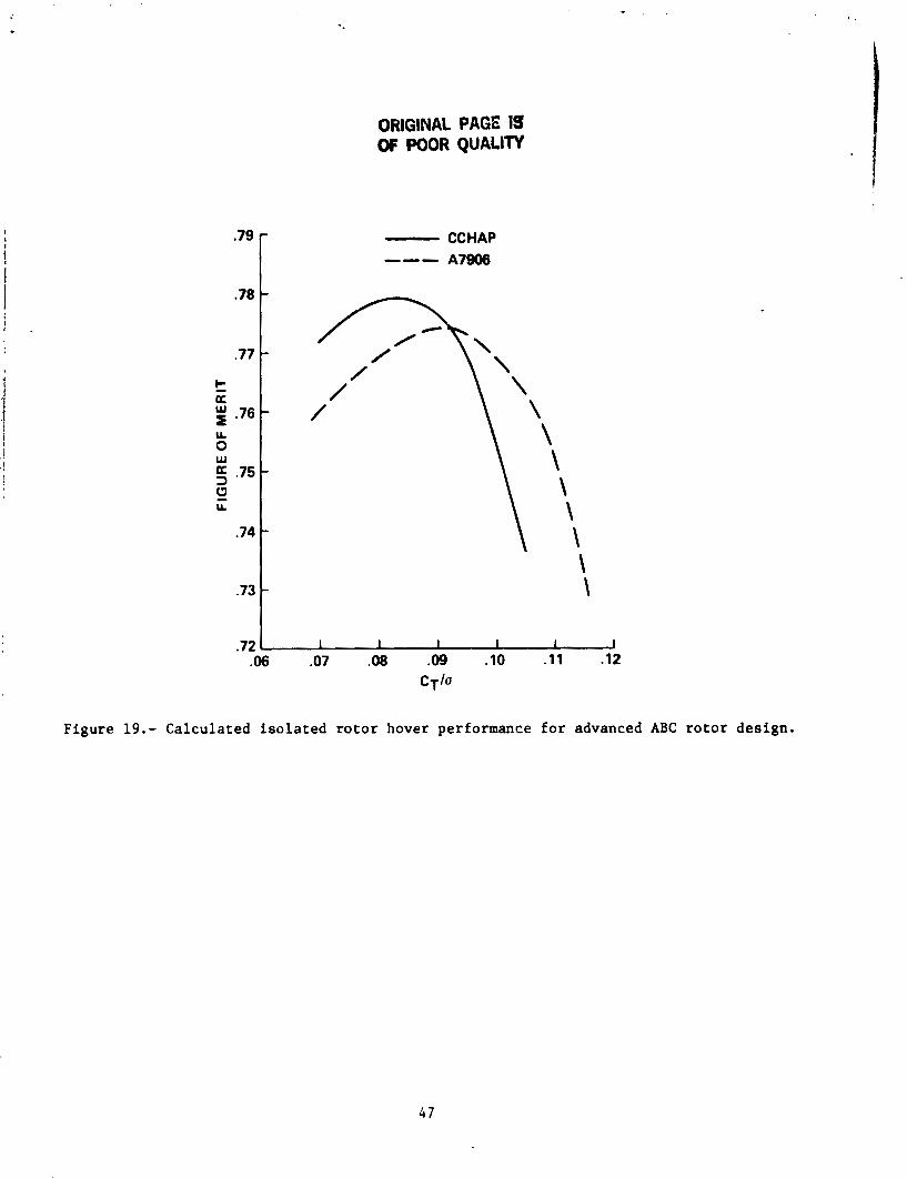
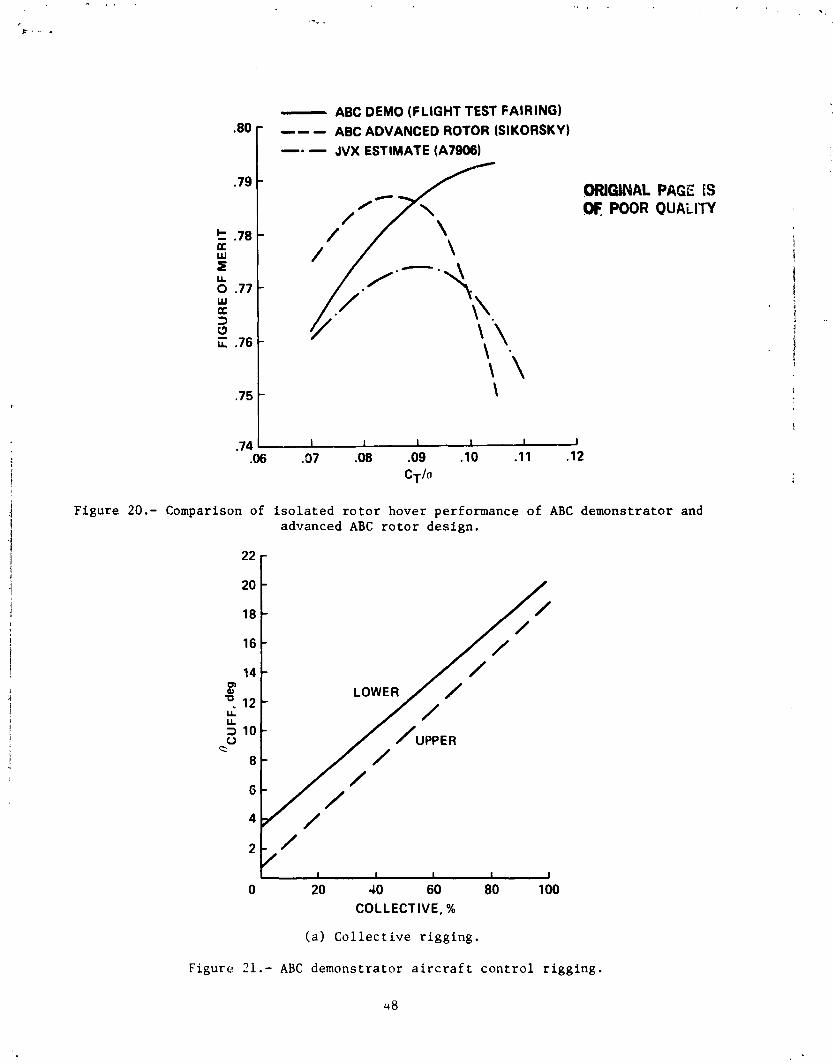
The c a l c u l a t e d performance of t h e advanced ABC r o t o r i s shown i n f i g u r e 19. The CCHAP r e s u l t s shown do not inc lude t h e ABC c o r r e c t i o n f a c t o r of r e f e r e n c e 7 . The d i f f e r e n c e s between t h e two methods a r e n o t viewed a s s i g n i f i c a n t . This r e s u l t is compared wi th t h e ABC demonstra tor r o t o r f i g u r e of m e r i t i n f i g u r e 20. Also shown, f o r the purpose of comparison, i s t h e es t ima ted performance taken f r o 3 re fe rence 7 . Th i s e s t i m a t e does inc lude t h e c o r r e c t i o n f a c t o r of r e f e r e n c e 7 (0.5-2%). Note t h a t both of the e s t i m a t e s show t h e impact of t h e reduced l i f t cap- a b i l i t y of t h e outboard a i r f o i l s st high v a l u e s o f CT/a.
CONCLUSIONS AND RECOMMENDATIONS
1. S i g n i f i c a n t improvements i n r o t o r LIDe a r e p o s s i b l e f o r t h e ABC i n high speed forward f l i g h t . These changes a r e due both t o changes i n o p e r a t i n g c o n d i t i o n s and t r im, and t o changes i n r o t o r aerodynamic des ign ( a i r f o i l s , t w i s t , and planform).
2 . The ~p t imum t r a d e of r o t o r performance, l i f t o f f s e t , and a i r c r a f t trim have not been i d e n t i f i e d . This e f f o r t should be accomplished ~ r i o r t o development of new ABC hardware.
3. Rotor RPM c o n t r o l and high r o t o r s t r e s s a r e problems t h a t were not r e so lved bv the SH-59A f l i g h t t e s t , a l though s o l u t i o n s have been proposed. Addi t ional e f f o r t is required t o reduce the o v e r a l l r i s k of an advanced ABC des ign . I t would be d e s i r - a b l e t o conduct add i t iv t lp l f l i g h t t e s t s wi th a c o n t r o l l a b l e e l e v a t o r t o i n v e s t i g a t e e f f e c t s of reduced r o t o r s t r e s s ( r o t o r p i t c h i n g moment). Also, f u r t h e r a n a l y t i c a l s t u d i e s and wind tunnl.1 t e s t s w i l l be r equ i red t o suppor t e i t h e r modi f i ca t ion of the demonstrator a i r c r a f t o r development of a new des ign . To demonstrate the f u l l poten- t i a l o f f u t u r e ABC J s s i g n s , a new r o t o r and an i n t e g r a t e d p ropu l s ion system which powers both r o t o r s ; ~ n d a u x i l i a r y p ropu l s ion dev ices t o t h e ABC d e m o n s t r a ~ o r would be necessa ry .
4 . The p resen t fo rward- f l igh t a n a l v s i s o f f e r s a s t e p forward i n r e a l i s t i c modeling of the ABC r o t o r . Addi t iona l modi f i ca t ions t o t h e code t o improve t h e
OHiGrltAL kl\Li OF POOR QUALITY
stability of the trim alyorithmr are highly derirable an would be an extenrion of the ABC portion of the code to include the wind tunnel mode trim optionr.
5 . An additional correlation of the prerent analysis with the ABC flight regions not covered in this study ie required to define the full capabilities and limitations of the analysis.
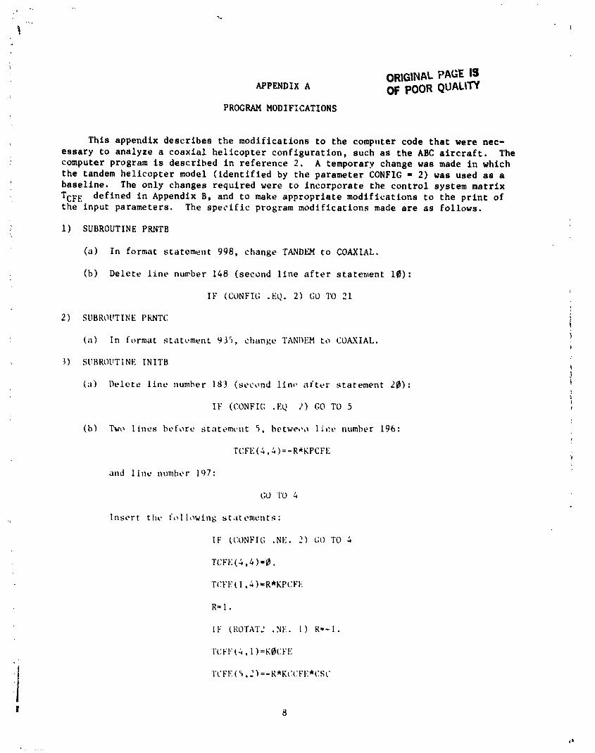
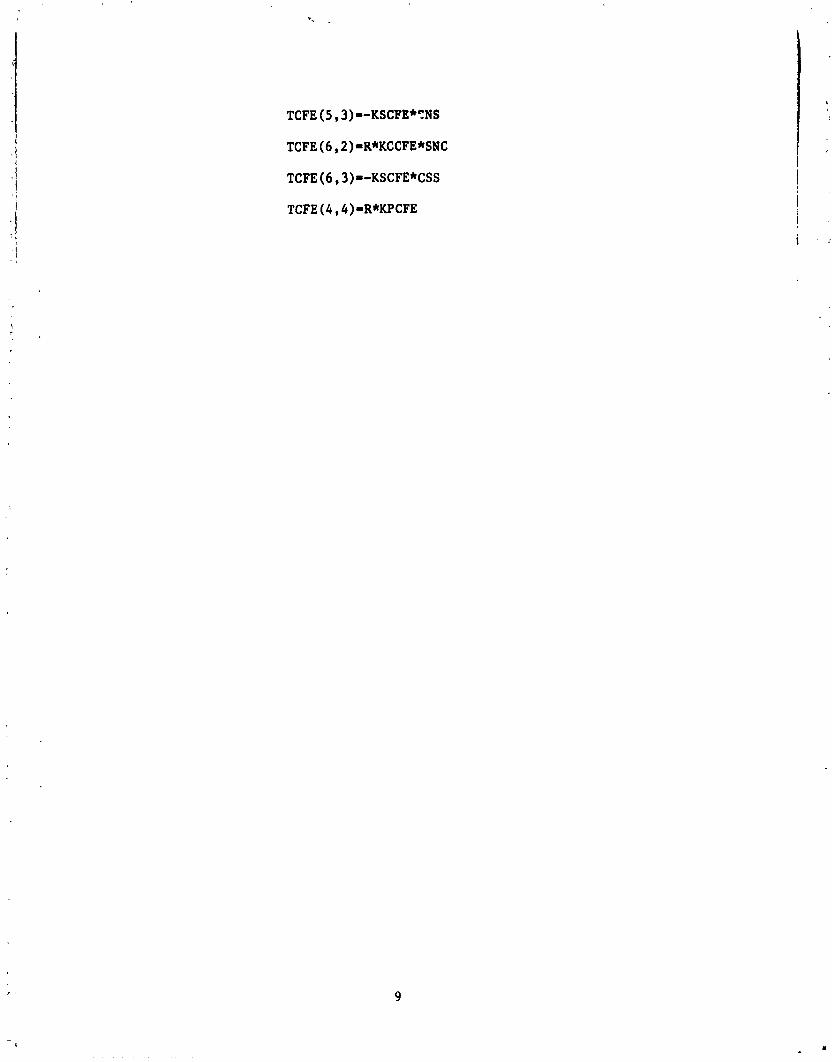
This appendix d e s c r i b e s t h e modi f i ca t ions t o t h e computer code t h a t were nec- e s s a r y t o analyze a c o a x i a l h e l i c o p t e r c o n f i g u r a t i o n , such a s t h e ABC a i r c r a f t . The computer program is desc r ibed i n r e f e r e n c e 2 . A temporary change was made i n which t h e tandem h e l i c o p t e r model ( i d e n t i f i e d by t h e parameter CONFIG = 2 ) was used as a base l ine . The only changes requ i red were t o i n c o r p o r a t e t h e c o n t r o l system m a t r i x
TCFE def ined i n Appendix B, and t o make a p p r o p r i a t e modi f i ca t ions t o t h e p r i n t of t h e input parameters. The s p e c i f i c program modi f i ca t ions made a r e a s fo l lows .
1 ) SUBROUTINE PRNTB
(a) I n format s ta tement 998, change TANDEM t o COAXIAL.
(b) Delete l i n e number 148 (second l i n e a f t e r statenlent 10) :
( a ) In format s ta tement 9 3 5 , change TANDEM t o COAXIAL.
3 ) SUBKOUTINE INITB
( a ) I'lelete l i n e number 183 (second l i n r a f t e r s ta tement 2 0 ) :
(b ) Two l ines before stntcment 5 , betwet),, l i c e number 196:
TCFE ( 4 . & )=-R*KPCFE
and l i n e nunh \ r 107:
APPENDIX B ORIGINAL PAGE IS W POOR QUALlW
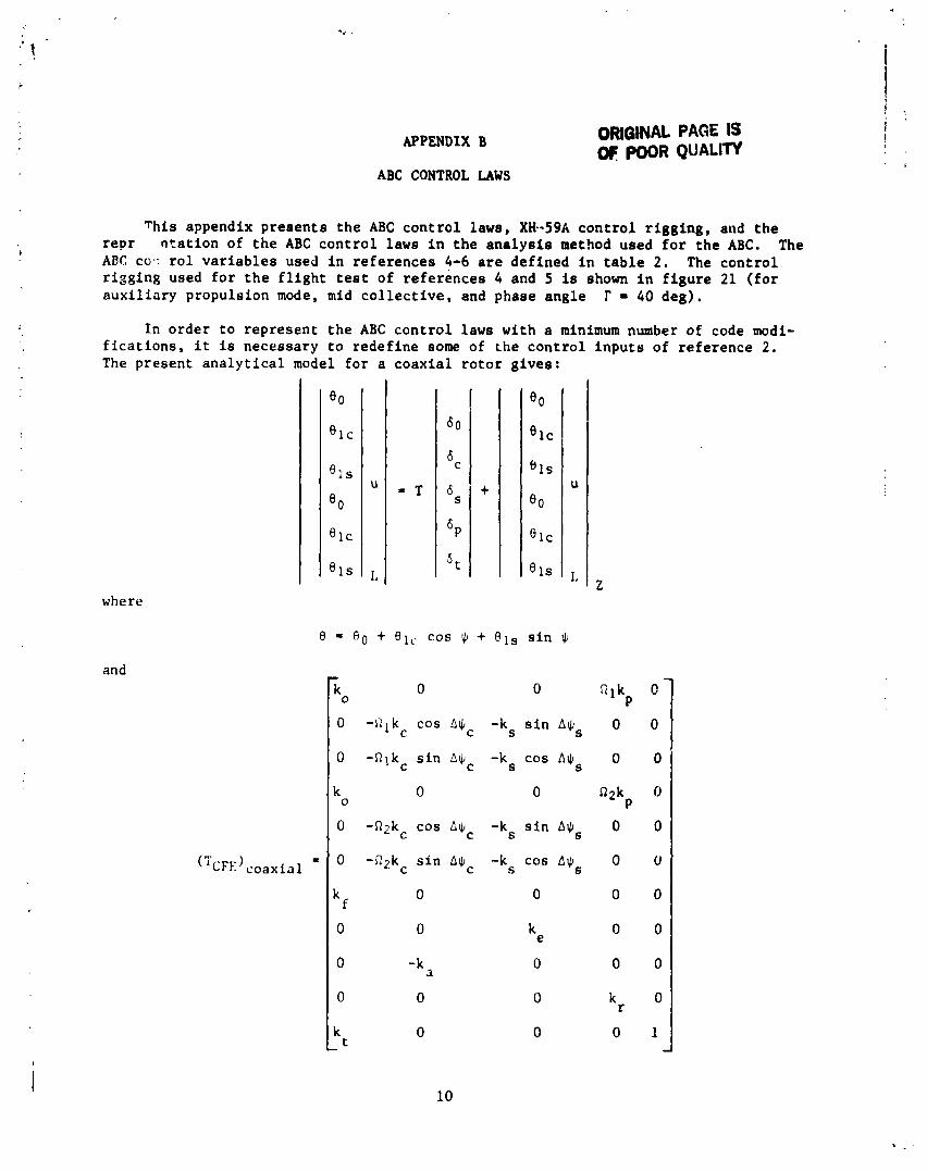
ABC CONTROL LAWS
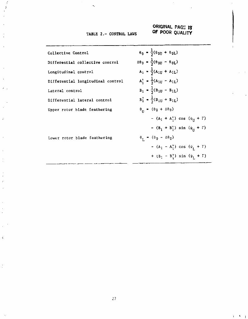
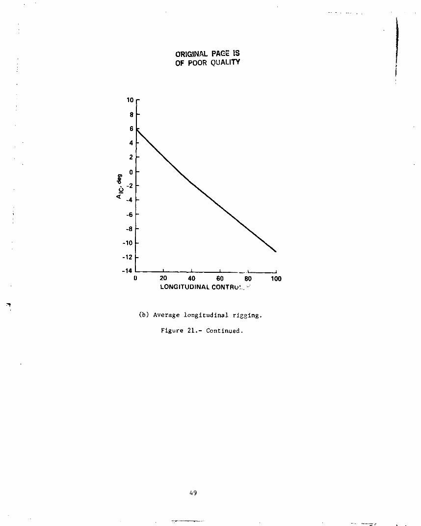
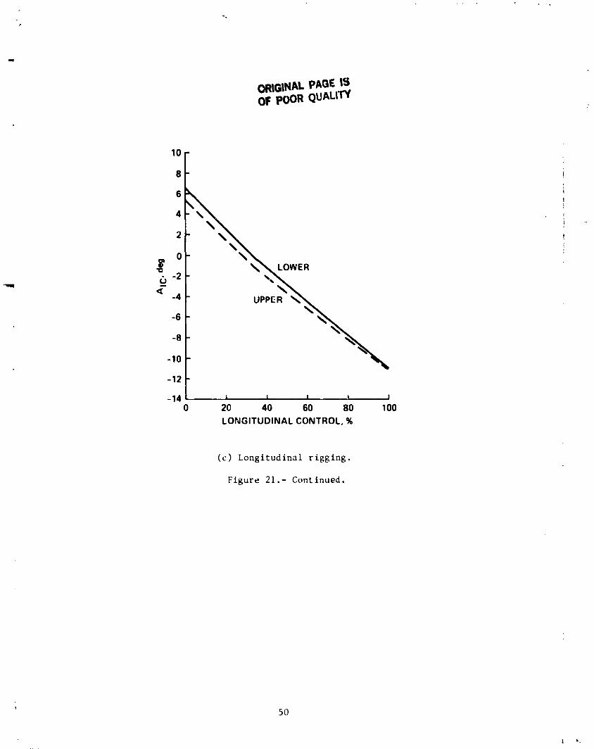
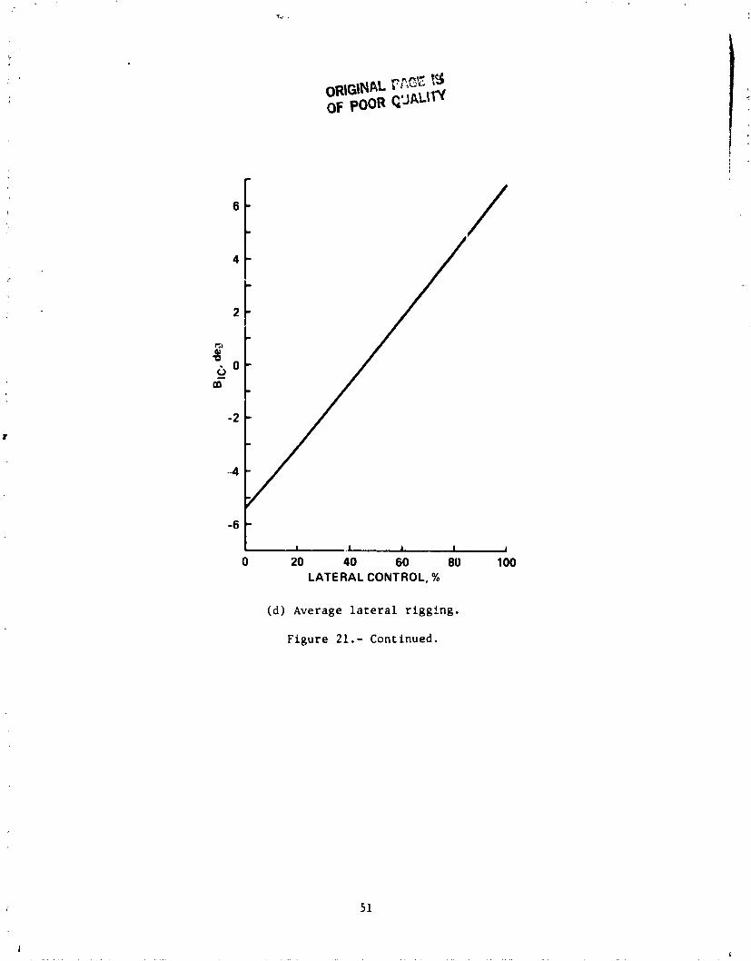
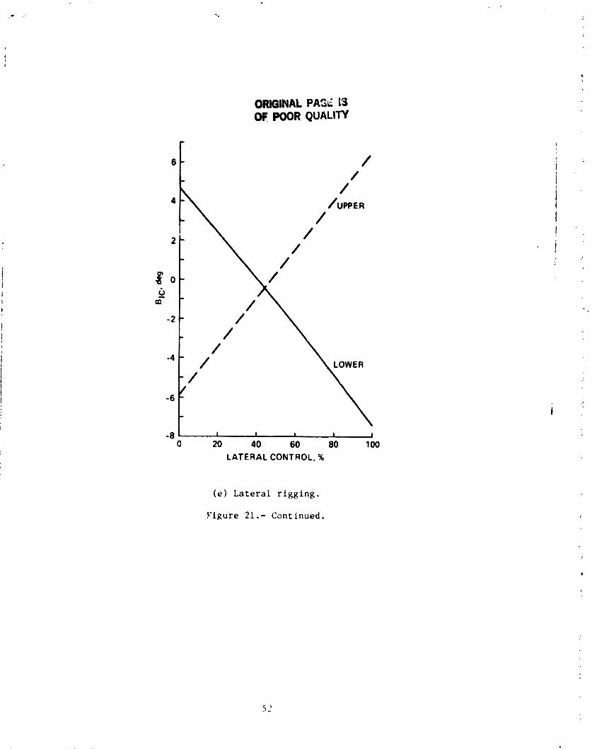
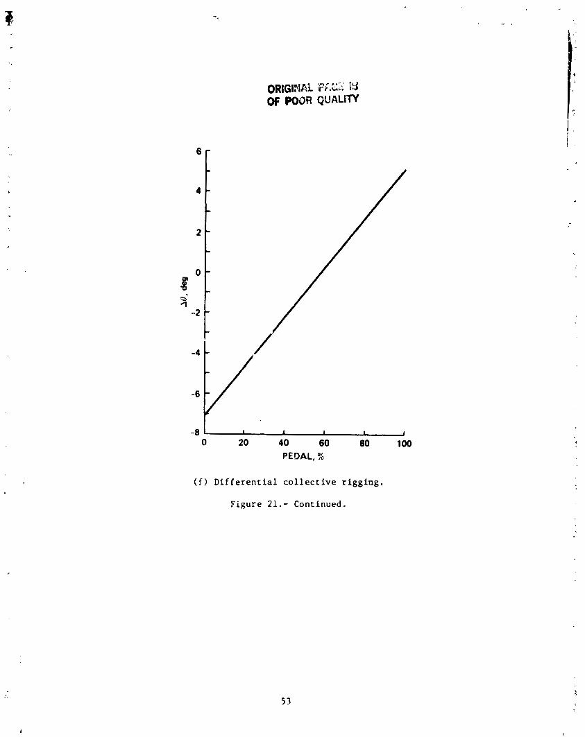
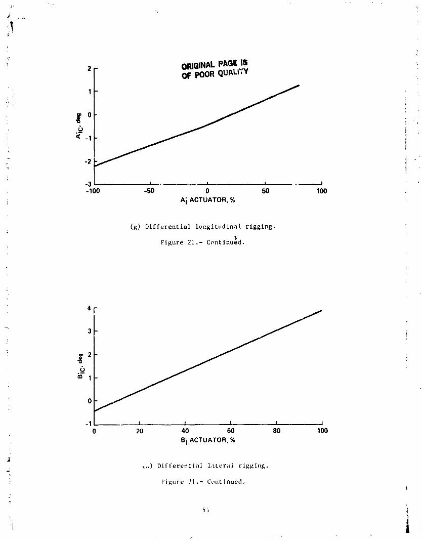
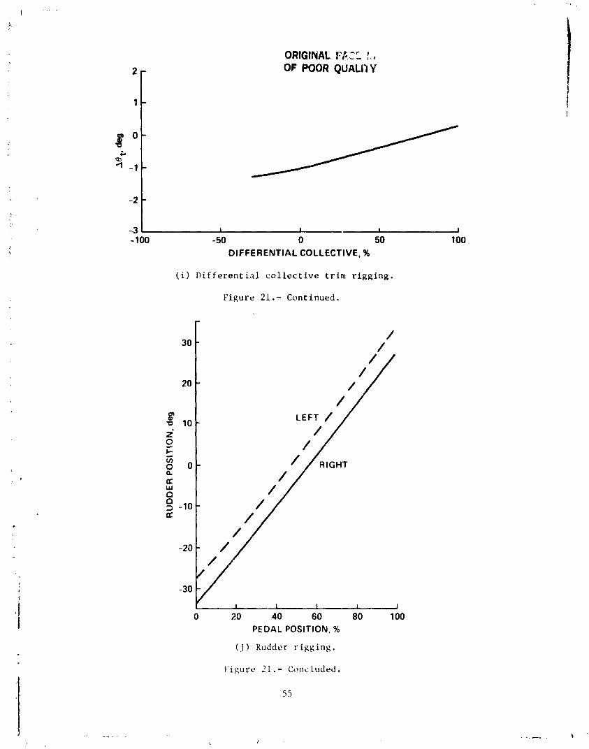
This appendix p r e s e n t s t h e ABC c o n t r o l laws, XH-59k c o n t r o l r i g g i n g , and t h e r e p r n t a t i o n of t h e ABC c o n t r o l laws i n t h e a n a l y s i s method used f o r t h e ABC. The AEC co,; r o l v a r i a b l e s used i n r e f e r e n c e s 4-6 a r e de f ined i n t a b l e 2. The c o n t r o l r i g g i n g used f o r t h e f l i g h t t e s t of r e f e r e n c e s 4 and 5 is shown i n f i g u r e 21 ( f o r a u x i l i a r y propuls ion mode, mid c o l l e c t i v e , and phase ang le r = 40 deg) .
I n o r d e r t o r e p r e s e n t t h e ABC c o n t r o l laws wi th a minimum number of code modi- f i c a t i o n s , i t is necessary t o r e d e f i n e some of t h e c o n t r o l i n p u t s of r e f e r e n c e 2. The p resen t a n a l y t i c a l model f o r a c o a x i a l r o t o r g i v e s :
where
and
0 -Q1k cos A$ -ks s i n AQ, 0 C C
0 -Rlkc s i n A$c -ks cos A9 0 S
k 0
0 0 Q2kp
0 -R2kc cos C$ -ks s i n A$, 0 C
0 -R2k s i n AqJc -k cos C S
t
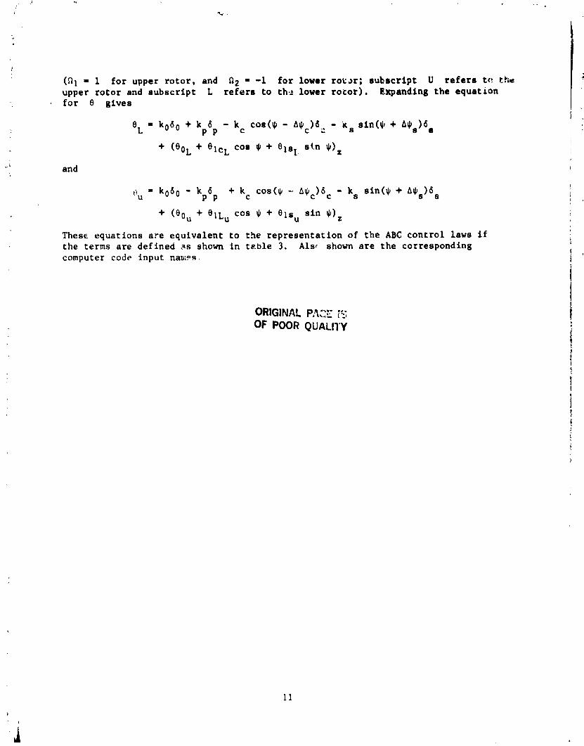
(ill = 1 f o r upper r o t o r , and n2 - -1 f o r lower t o t a r ; subfsc r ip t U r e f e r s t c ! the upper r o t o r and s u b s c r i p t L r e f e r s t o thg lower r o t o r ) . Expanding t h e equa t ion f o r 0 g ives
and
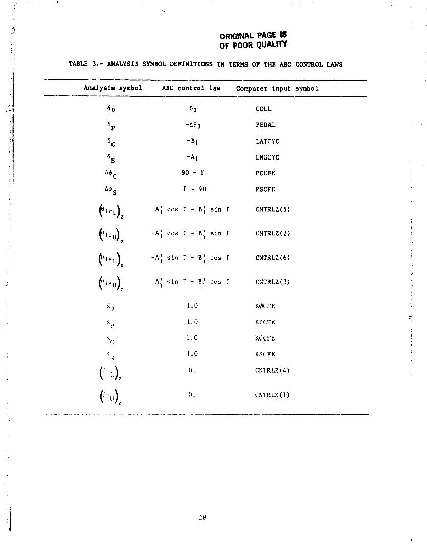
These equa t ions a r e e q u i v a l e n t t o the r e p r e s e n t a t i o n of t h e ABC c o n t r o l laws if t h e terms a r e de f ined as shown i n t a b l e 3. A l s r shown a r e t h e corresponding computer code inpu t n a w s .
ORIGINAL P,CE K OF POOR QUALITY
ORlQlNAL PAGE OF POOR QUALITY
APPENDIX C
ANALYSIS INPUT DATA
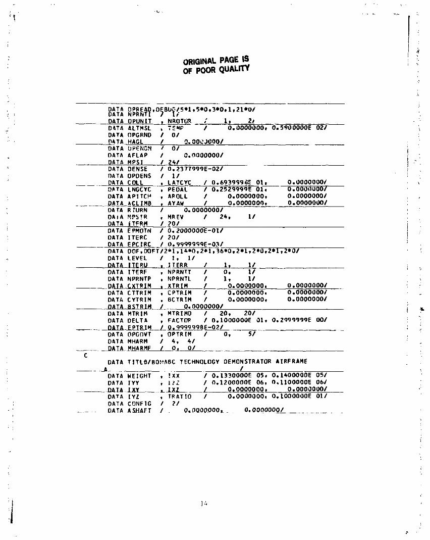
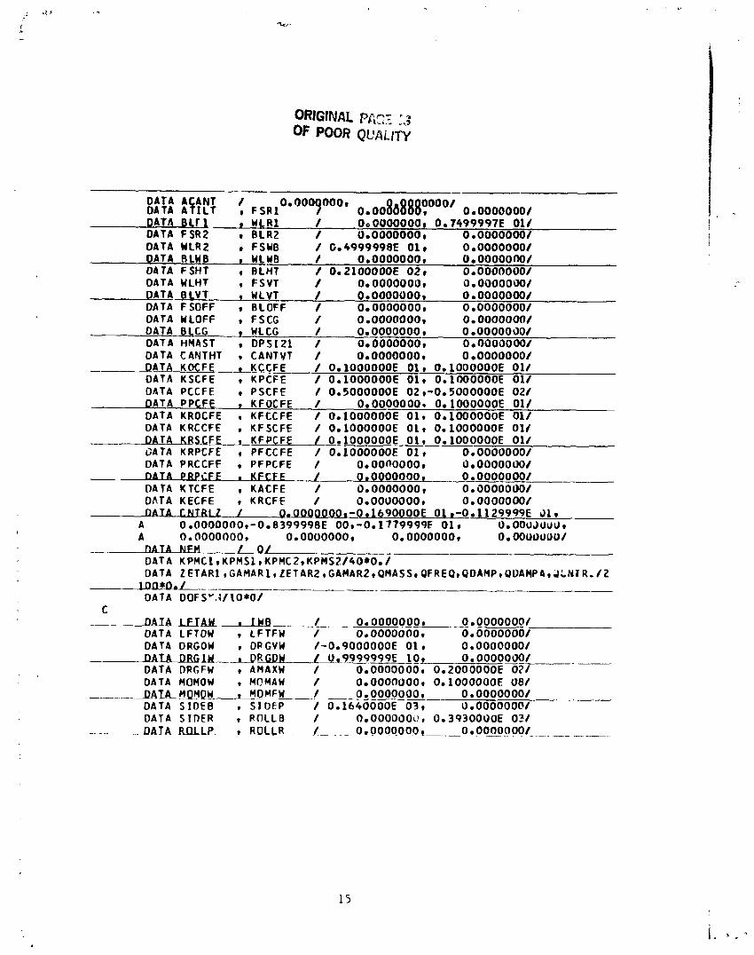
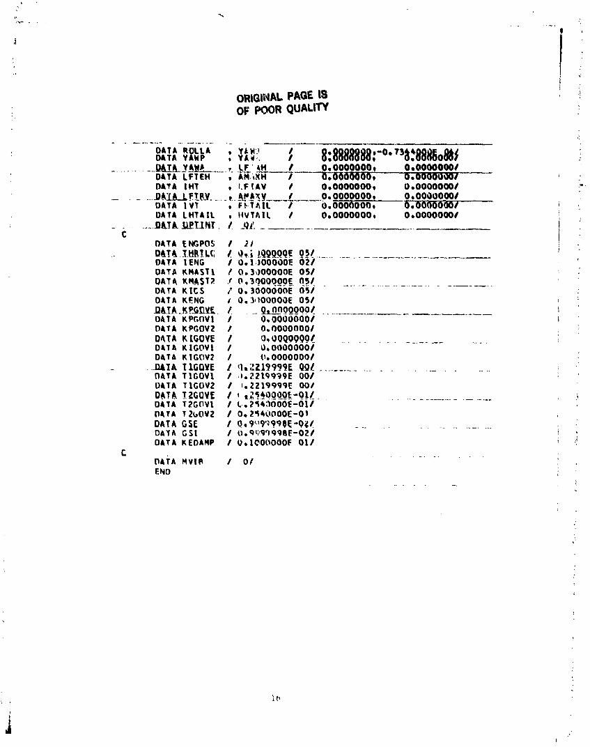
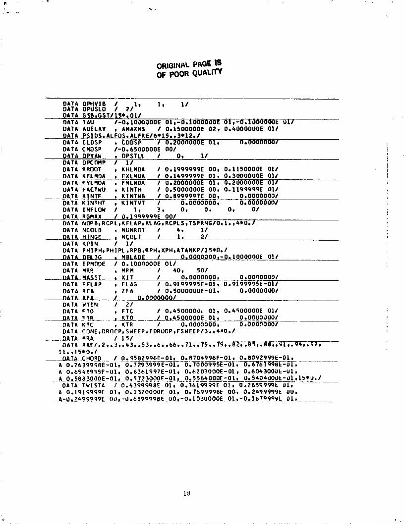
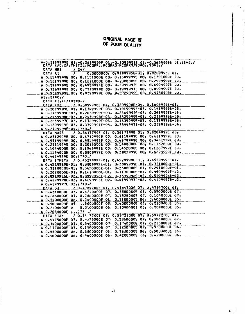
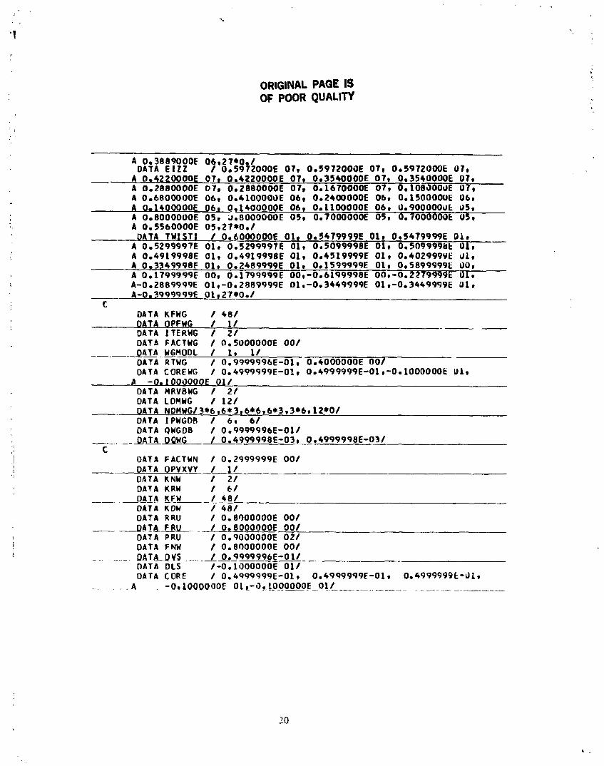
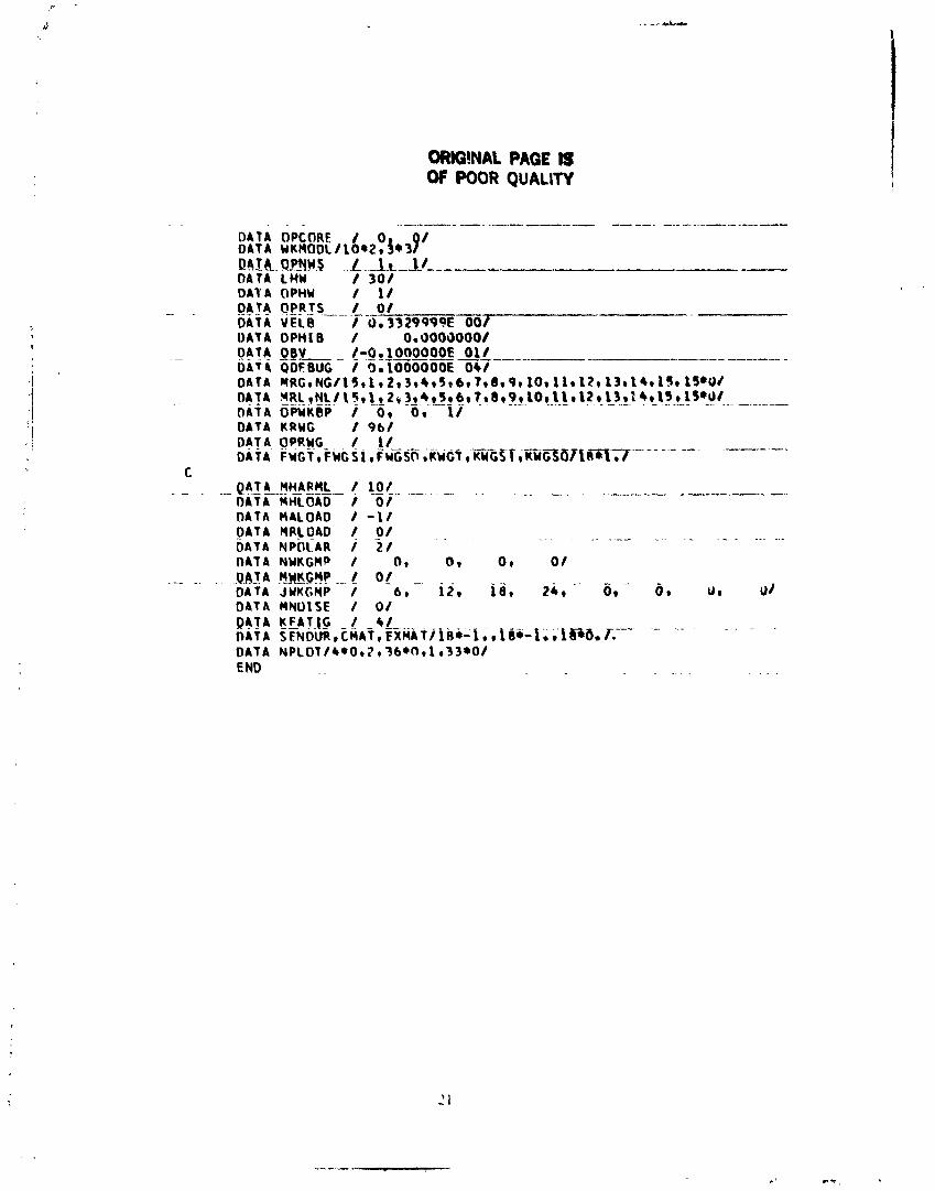
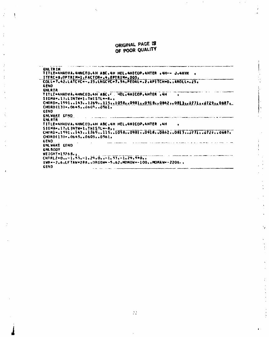
T h i s appendix p rov ides t h e comple te i n p u t d a t a used t o model t h e ABC a i rcraf t . The v a r i a b l e s a r e d e f i n e d i n r e f e r e n c e 2. The f o l l o w i n g l i s t i n g s a r e p r e s e n t e d :
1) The b lock d a t a r o u t i n e s f o r t h e XH-59A ABC demons t r a to r a i r c r a f t .
(a) The t r i m / a i r.f rsme black d a t a .
( b ) The : o t o r 111 (upper r o t o r ) b lock data. The r o t o r 112 ( lower r o t o r ) i n p u t is i d e n t i c a l t o t h a t f o r r o t o r C1, excep t f o r a change i n t h e d i r e c t i o n o f r o t a t i o n (ROTATE = I ) , and a p p r o p r i a t e changes t o t h e TITLE and TYPE parameters .
2 ) The n a m e l i s t i n p u t r e q u i r e d t o ana lyze an advanced ABC h e l i c o p t e r f o r J V X , r c l . n t i ve t o t h c XH-S9i\ b l o c k d a t a a s cr 1):iseline.
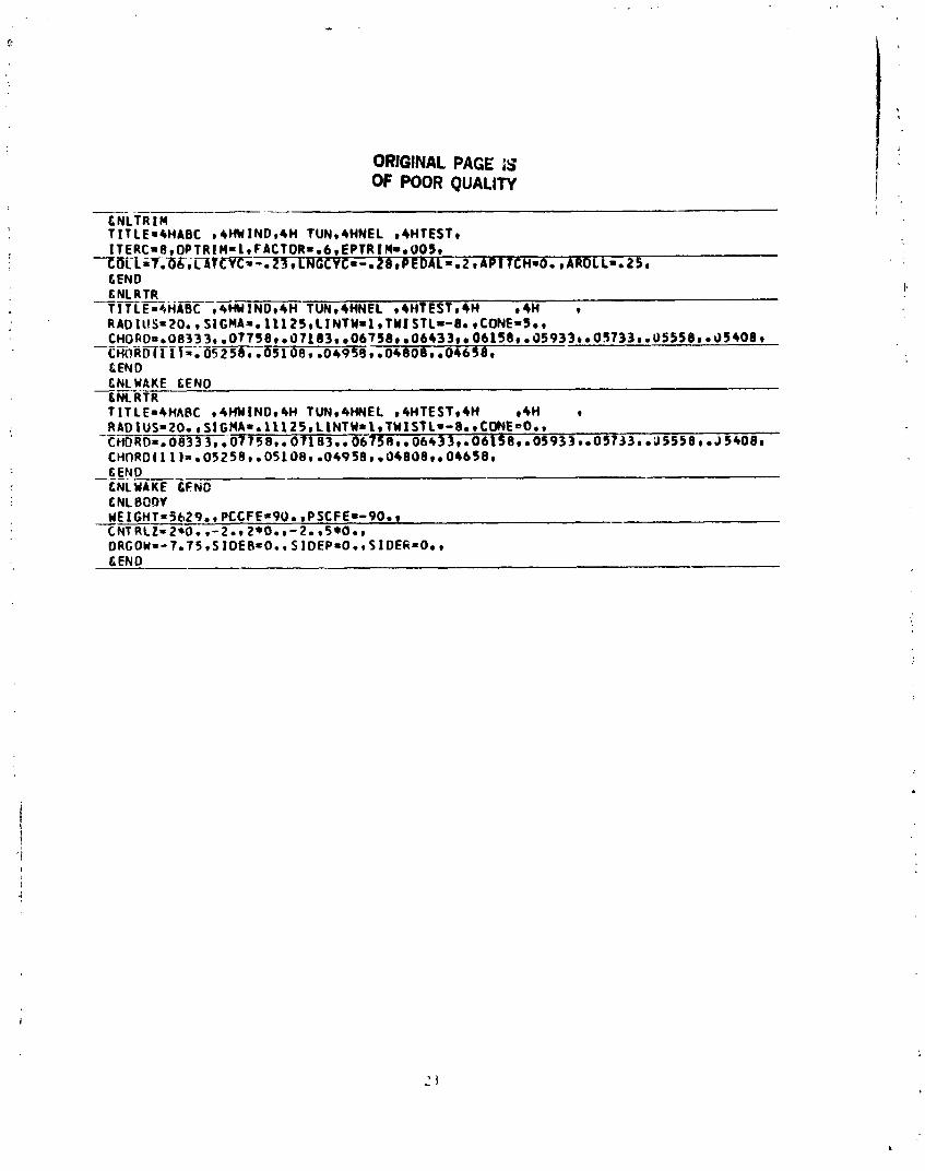
3 ) I'hc namc.list i npu t rcquirc.d t o a n a l y z ~ t h c AMC r o t o r used i n t h e wind t u n n e l t e s t , rc1 ; i t ivc t o t h e XH-59A b lock d c t a a s a b a s c l i n e .
ORIGINAL N t G E IS OF POOR QUALIW
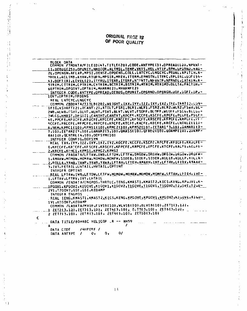
---- ---- - BLOCK DATA COMMON / T M O A T A / F I L E I O ~ 4 ) r T I T L E ~ 2 O ~ r C O D E r A N f Y P E ~ 3 ~ r O ~ R E A ~ l i ~ l c N P R M 1 -
RFAL L ATCYCILNGCVC
I N T E G E R ENGPOS
C . . - DATA I lJLE/BQHABC YELJCO? . -R -- XH59 . . .- . _ .
A / DATA CODF / 4 t i P E R F / D A T A A N T Y P E / 01 0 s o/ . . -.. . -
ORIGINAL PAGE 1s OF POOR QUALITY
D A T A O P R E A D r D Bb / 5 * 1 r 5 * 0 ~ 3 * 0 ~ 1 t 2 1 * 0 i D A T A N P R N T I 5 f i
D A T A OPGRND / O / DATA. H A G L / 5.30L 'JOOOI D A T A UPENCN / O/ DATA A F L A P / 0.0000000/ D A T A M P S I / 2 4 / D A T A DENSE 1 0 . 2 3 7 7 9 9 9 E - 0 2 / OATA OPDENS / 1/ DATA C O L L 9 L A T C Y C / 0 . 6 9 3 9 9 9 5 2 O l t O.OOOOOM)/ D b T A LNGCYC r P E D A L / 0 . 2 5 2 9 9 9 9 E 0.0000000/
-- - D A T A A C L I M B , AYAW / 0~0000000r 0.000001)0/ DATA R TURN / 0~0000000/ D A I A XPS!R r MREV I 2 4 ~ 1 / D A T A i T F R J 4 / ?O/ OA TA E PMOTN / 0. 2 0 0 0 0 0 0 E - O X / D A T A I T E R C / 2 0 /
D A T A L E V E L / I r 1/ D A T A I T E R U r I T E R R / 1 r 1 / D A T A I T E R F r NPRNTT / 0 I 1 / D A T A NPRNTP r N P R N T L / I r 1 /
D U f R I M t-XTRIH.- / 8.0000000 9 0.0000000/ D A T A C T T R I M r C P T R I M / 0 ~ 0 0 0 0 0 0 0 ~ 0 ~ O O O O O O O / D A T O C Y T R I M r B C T R I M / 0e0000000~ 0~0000000/
D A T A B S f R I H L 0 . O 0 0 0 0 0 0 / D A T A M T R I M r M T R I M D / 209 2 0 / D A T A D E L T A r FACTOR / 0 ~ 1 0 0 0 0 0 0 E 31r 0 . 2 9 9 9 9 9 9 E 0 0 4
o A r A E P I R I Y ~ - L Pa 9999 9951E-02 - D A T A OPGOVT r O P T R I M / or 5 / D A T A MHARM / 41 4/ QAIA_ I r IFARMF / O r 0 1 --
C D A T A T I T L 0 / 8 0 2 4 B C TECHNOLOGY DEMONSTRATOR A I R F R A M E
-A I DATA W E I G H T r ! X X /0.1330000~ 0 5 r 0 . 1 4 0 0 0 0 0 E 05/ D A T A I V Y r I ? L / 0 * 1 2 0 0 0 0 0 E 069 O r l l O O O O O E 064
L A & . . ~ U U - . ~ 0 L O 0 0 0 0 0 0 9 0.000001)0/ - D A T A 1 Y Z 9 T R A T I O / 0.0000000~ 0 . 1 0 0 0 0 0 O E 01/ D A T A C O N F I G / ? /
. - . - DATA ASHAFT / . 0. P Q O ~ O O O r _ _ 0 * 0 0 0 0 _ 9 0 0 / . . .
ORIGINAL PAS: 13 OF POOR Q C A L l N
- DATA ACANT / 0.000 0001 D A T A A T I L T . F S R ~ 9 0.008~888. OooO' o.ooooooo/ DATA BLr 1 r WLRl / .Oc 0800000r 007499997E 014 DATA FSR2 r BLRZ / 0.OOOOOOOr 0.0000000/ DATA ULRZ r FSUB / 004999998E 01 r 0~0000000/ DATA RLWB r WLWB / 0~0000000r 0.00000rX)/ DATA FSHT r BLHT / 0a2100000E 02. 0.0000000/ DATA WLHT r FSVT / 00000000G 0.0000000/ OAT A BLVT r WLVT / 0.000000Or 0.0000000/ DATA FSOFF r BLOFF / 0~0000000~ 0~0000000/ DATA WLOFF r FSCG / 0~0000000~ OaOO0000/ DATA BLCG r WLCG / 0~0000000 r 0~0000000/ DATA HMAST r DPSI2l / 0~0000000~ 0.0000000/ DATA CANTHT r CANTYT / 0~0000000r 0.0000000/ DATA KOCFE r K S F E / 0.1000000E O l r 0.1000000E 011 DATA KSCFE r KPCFE / 0~10000OOE O l r 0.1000000E 01/ DATA PCCFE r PSCFE / 0.5000000E 02 1-0. 5000000E 02/ DATA PPCFE KFOCFE / 0~0000000~ 0~1000000E 01/ D A T A KROCFE KFCCFE / O ~ l O O O O O O E O l r 0~1000000E 01/
DATA KRSCFE 9 KFPCFE / 0.1000000E 019 0~1000000E 01/ DATA KRPCFE r PFCCFE / 0~lOOOOOOE 01 r 0.0000000/ D A T A PRCCFF r PFPCFE / 0. 00n0000~ 0.00000cH)/
- / 0~0000000r OmOOOO0OO/ DATA KTCFE r KACFE / 0.0000000 r 0.3000000/ DATA KECFE r KRCFE / 0.001]0000 r Oa0000000/ D A r A . t N f R L Z O . Q . D O O O ~ ~ O ~ 1 6 9 0 0 0 0 E 01 r-001129999E 31 r
A 0.0000000r-0.8399998E 00,-0.1779999F 01 r 0.00c)JU~c)r A 0m000000Or 0.0000000, 0~0000000~ O.OOOOUOL)/
--QI DATA KPMCl r KPHS l r KPMCtrKPMS2/40*0o/
0.0000000/ - - D A T A L F T A W B L _L !5wm20000 1 - .- DATA LFTDW r LFTFW / O.OOOOOOO* 0~0000000/ DATA DRGOW r OPGVW /-0.9000000E 01 e 0~0000000/
DAfAw I D R W / 009999999E 1 0 ~ 0.0000~1)0/ -- D A T A DRGFW * AHAXW / 0.0000000r 0.2000000E 021 DATA MOHOW r HFHAM / 0.0000000r 0.1000000E 08/
MOMFU / - [lAIAL-ilQ!!PW 1- 0.0000000~ o.ooooooo/ D A T A S I O E B r S I O E P / 0.1640000E 03r 0.0000000/ D A T A S I D E R r POLLB / 0. OOOOOOU * 0.393OOOOE 03/
-. --.- -~ -. DATA RLILLP. r ROLLR 1- . .- 0.000900Pr Oroomg00/
- . . . . . . . . U Y 4 Y E . .,*.. OATA LFTEH
. . - - O A T A Hvrn 1 01 END
ORIGINAL PAGE IS OF POOR QUALITY
L DATA T l T l F /ROHABC TTCt(Nn1OGY DFMT)P(STRlTOR -- UPPER H ~ T u ~ (
A / D A T A T Y P t /WUPR I DATA Y T I P N e RADIUS / O m 3 5 0 0 0 0 0 E 0 3 , 0*1AOOOOOE 071 P A T h S I G M A 9 G A M M A / 0 . 1 2 7 0 q 9 9 F 0 0 , 0 . 5 1 1 1 3 9 9 F 0 1 / O A T A NBLAOC / 31 11476 T ~ A H P O ~ TI I~HPC r TOAMPR ~ N U G C ~ N I I G S ~ G I ) A M P C ~ G D A H P S ~ ~ ~ A M P L ~ L U ~ N P M ~ L l l
ORIGINAL PAGE 1s OF POOR QUA LIP^
-- ---- DATA O P t I V I B / 1. DATA OPUSLD / 2 /
1 r 1 /
DATA G S B r G S T / 1 5 * ~ O l / DATA T AU / -0 .1030000E O l r - 0 . 1 0 0 0 0 0 0 t O l r - O . 1 a p OATA ADELAY r AMAXNS / O.~SOOOOOE 0 2 1 0 . 4 0 0 0 0 0 0 E 01/ DATA PSIDS, ALFDSrALFRE/6*1Sm,3*12./ DATA CLDSP r CDDSP / 0.20000QOE 01, 0 0000000/ DATA CHDSP 1-08 6SOOOOOE 001 DATA OPYAW r OPSTLL / 0 I 1 / DATA OPCOHP / 1/ DATA RROOT r KHLMDA 1 O a l 9 9 9 9 9 9 E 009 0.1 l5OOOOE 01/ DATA K F L M D A , FXLHOA / 0 . 1 4 9 9 9 9 9 E O l r 0 . 3 0 0 0 0 0 0 E 011 DATA FYLMDA r FMLMDA / 0 ~ 2 0 0 0 0 0 0 E O l r 0.20OOOOOE O1/ OAT A FACTWU r K I N 1 H / 0 . 5 0 0 0 0 0 0 E 001 0. 1 1 9 9 9 9 9 E 01/ DATA K!NTF r.-KJNTWB / 0 . 8 9 9 9 9 9 7 E 00. 0~0000000/ DATA K I N T H T r K I N T V T / 0.0000000~ O.OOOOOOO/ DATA INFLOW / 1 r 3 r 0 r 0 r 0 r O/ DATA RGHAX / 0.1999999~ -OO/ DATA N O P B ~ R C P L * K F L A P ~ K L A G ~ R C P L S ~ T S P R N G / O ~ 18 r4*00 1 DATA NCOLB r NONROT / 4 9 1 /
DATA P H l P H r P H I P L rRPBrRPHrXPHrATANKP/15*Oo/ DaJA DFL3G HBLADE / 0 ~ 0 0 0 0 0 0 0 ~ ~ 0 ~ l O O O O O O E 01/ DATA EPMOOE / 0 . 1 0 0 0 0 0 0 E 01/ DATA HRR r MPH / 40. 5 0 /
oArAwz;-- 0.0000000~ 0. ooC)ooo0/ DATA E F L A P r € L A G / 0 0 9 1 9 9 9 9 5 E - 0 l r 0 0 9 1 9 9 9 9 5 E - 0 1 / DATA RFA r Z F A / 0 ~ 5 0 0 0 0 0 0 ~ - 0 1 9 0.000001)0/
---_l-O.OQQOOQQ/ DATA W T I N / 2 /
DATA CONEIDROCPI S W E E P I F O R U O P ~ F S W E E P / ~ . ~ ~ * O ~ / - _ _ P A I k Y R l L L l 5 L
DATA RAE/ .2 r .3 r .43 r .53 r .6 r .66 r .71 r .75 r .79 r .82 r . 8 5 r ; 8 8 r . ~ l r . 9 6 r i T - - - -
ORIGINAL PAGE IS OF POOR QUALITY
DATA M R I / 24/ DATA R I I 0~0000000. 009199995E-01, 009209996t-31r
- ~
A 0.7369999~ 00; 0.7370999~ 00, 0.7999997E 00, 008999997E 33, A 009389999E 00, 0.9390999E 00, 009729999E 001 009730999E UUI A10 r27*O./
DATA X I r X C / l O 2 * O . / DATA KP2 / 0.3899998E-04, 003899998E-04, 0.1699999E-U3r
A 0.2079999E-03- 0.1749999E-03, 0.1919999E-03, 001619999E-03,
A 0.6112999E 001 0.6712999E 001 0.6119999E 009 006119999E 009 A 005419999E 001 9.5519999E 00, 0.4379999E 009 0.3431999E 30r A 0.2531999E 00* 0.2016000E 00. 0.1488OOOF 001 0.1152003k 53e A 0.1044000E 009 0.1465999E 00, 0.1452000E 001 Om126799YE 009 A 0.1194900E 00LeJ803999E 001 0.3803999E 009 Om4624999E U O t A 0.4624999E 00,27*0./
O A T A I THETA / 0. 452999qr-01 0.4529999E-Ol r 0 0452999SE-Ul I A -01. - O a38099 99 E - W E - 0 1 , 0.3210003t-31, A Om3210000E-01, 0.3650000E-01, 0.3500000E-019 0.291OOOUE-019 A 0.2020000E-0 19 0m1610000E-011 0.117OOOOE-01, 009599999E-02 r A OLBpPp996E-Q7. Q.8999996E-021 OmT699996E-029 00549999bk-02, A 004699998E-021 0.4699998E-02. 0m4199997E-02, 0.4199997E-U2r A O.4L9999tE-02t 27*O./
DATA GJ / 0.4784700E 0 7 ~ Oo4784700E 07. 0.4784700E O7r A 0.4210000E 079 0.4210000E 07, 0.3500000E 07, 0.3500003E 079 A 0-2860000E 07r 0.2860000E 079 0.1528000E 07, O.lO4OWUt 07,
ORIGINAL PAGE IS OF POOR QUALITY
A 0.6800000E 06. 0~4100003E 06. Oa24W000E Obr Oa150000UE 06,
DATA T W I S T 1 / 0~6000000E 01, 0a5479999E 01, Oa54799WE 011 - A Oa5299997E O l e Oa5299997E 019 Oa5099998E 019 Oa5099991t O l r A Oa4919998E 01s 0a4919998E O l r Oa4519999E 011 Oa402999YE 31, A 0.3349998F 019 0.2489999E O l r Oa1599999E O l r Oe5899999E 30r A 011799999E 009 0a1799999E 00,-Oab199998E 009-Oa2279999f OAr
DATA KFHG / 48/ DATA OPFWG / 1/ -- - DATA ITERWG / 2 / DATA FACTWG / 0a5000000E 00/ DATA WGHOOL / l r I/ OATA R f W G / 0e9999996E-01, Oa4000000E 00/ DATA COREWG / 0.4999999E-01, Oa4999999E-019-0. 100OOOOE UAr - 0000E 01/ DATA HRVBWG / 2 / DATA LOHWG / 12/ DATA NDHWG/ 3*6 16*3,6*6r6*3r3*6r 12*O/ DATA IPWGOR / 69 6/ DATA QWGDB / Oa9999996E-01/
- _ P L I L 4 D Q w C / Oe49W998E-03r Oa4999998E-03/ C
OATA FACTWN / 0.2999999E 00/ DATA OPVXVY / 1/ -- DATA KNW / 2/ DATA KRW / 6/ DATA KFW / 481 ---- --- -- DATA KOW / 48/ DATA RRU / 0a8b00000E 00/
D A T A FRU _- / 0a8000000E 00/ DATA PRU / Oe9000000E O2/ DATA FNW / Oa8000000E 00/
ORM!NAL PAGE IS OF POOR QUALITY
DATA OPCORE / 0 / DATA UKMODL / I W 2 . 3 * 3 9
DATA KRWG / 961
DATA MALOAD I - I / OATA MRlOAD / 0/ . . . . . . - . -. - - - . . - . - - A -. . . . DATA NPOLAR i 2 1 DATA NYKGMP / 0 e 0 . 0 1 0 /
.. . . . Q M A flMF!!!' .- l 0.1 - DATA JwuGnP / iZ, iij, 24. . ' 0 , 0 , U, ot D 4 T A M N U l S E I O /
SNLW?KE bFN-B,. . - .-. SNL RTR
ORIGINAL PAGE SY OF POOR QUALITY
--- ---------- - CNLTRIM TITLE=4HABC t4HWINDtIH TUNt4HNEL e4HfESfe
CEND
c END - CNLWAKE CENC CNL Boor WEIGHT*5629.~ PCCFE=9Oo mPSCFE=-9Oo, - - CNTRLZ=Z*Oo r-2.9 2 * 0 0 r - 2 0 t5*Oot
APPENDIX D ORldlNAL PAGE IS OF POOR QUALlW
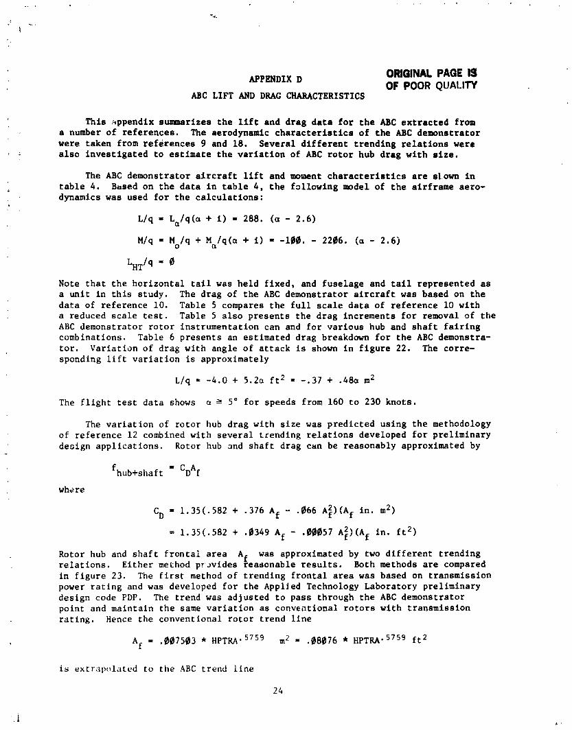
ABC LIFT AND DRAG CHARACTERISTICS
This kppendix summarizes the lift and drag data for the ABC extracted from a number of references. The aerodynamic characteristics of the ABC demonstrator were taken from references 9 and 18. Several different trending relations were also investigated to estimate the variation of ABC rotor hub drag with size.
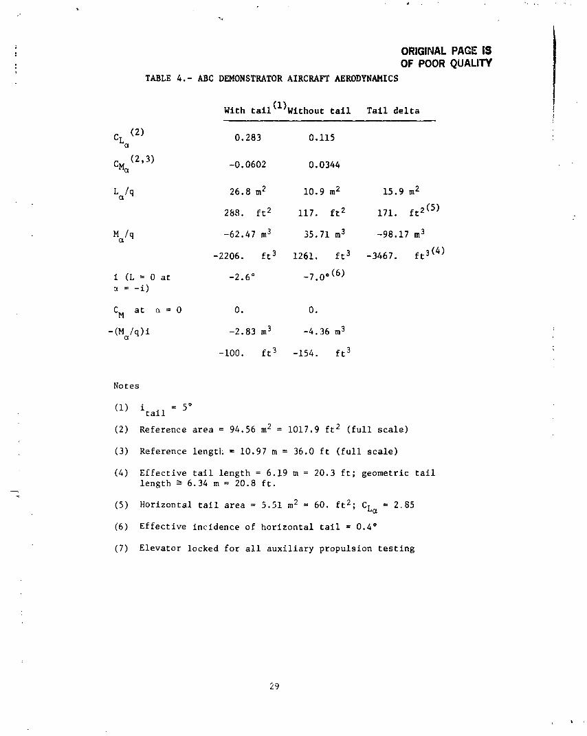
The ABC demonstrator aircraft lift and moment characteristics are sLown in table 4. Based on the data in table 4, the fallowing model of the airframe aero- dynamics was used for the calculations:
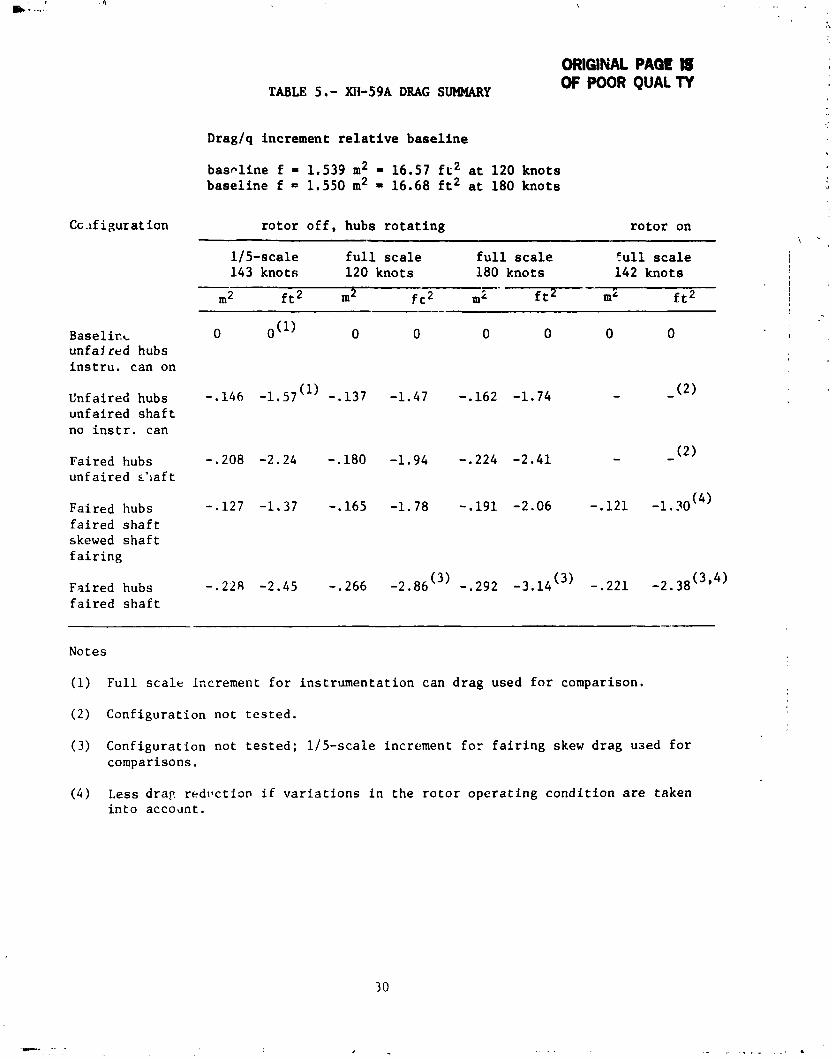
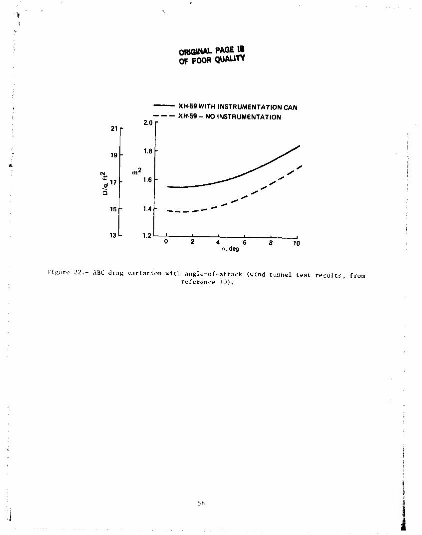
Note that the horizontal tail was held fixed, and fuselage and tail represented as a unit in this study. The drag of the ABC demonstrator aircraft was based on the data of reference 10. Table 5 compares the full scale data of reference 10 with a reduced scale test. Table 5 also presents the drag increments for removal of the ABC demonstrator rotor instrumentation can and for various hub and shaft fairing combinations. Table 6 presents an estimated drag breakdown for the ABC demonstra- tor. Variation of drag with angle of attack is shown in figure 22. The corre- sponding lift variation is approximately
The flight test data shows a " 5' for speeds from 160 to 230 knots.
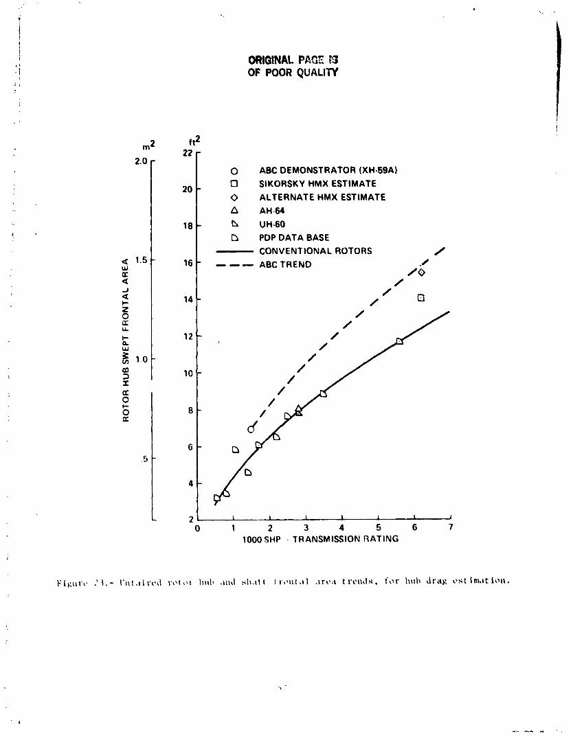
The variation of rotor hub drag with size was predicted using the methodology of reference 12 combined with several trending relations developed for preliminary design applications. Rotor hub and shaft drag can be reasonably approximated by
where
CD = 1.35(.582 + .376 if - .066 A:)(A~ in. m2)
= 1.35(.582 + .0349 Af - .I0057 A$)(A~ in. ft2)
Rotor hub and shaft frontal area Af was approximated by two different trending relations. Either method pr~vides reasonable results. Both methods are compared in figure 23. The first method of trending frontal area was based on transmission power rating and was developed for the Applied Technology Laboratory preliminary design code PDP. The trend was adjusted to pass through the ABC demonstrator point and maintain the same variation as convrational rotors with transmission rating. Hence the conventional rotor trend line
is extrapolated to the ABC trend line
1. Johnson, W.: Development of 8 Comprehensive Analysis for Rotorcraft. Vertica, vol. 5, no. 2 and no. 3, 1981.
2. Johnson, W.: A Comprehensive Analytical Model of Rotorcraft Aerodynamics and Dynamics. Part I, NASA TM 81182, June 1980; Part I1 NASA TM 81121. July 1980; Part 111, NASA TM 81184, June 1980.
3. Kocurek, J. D., et al. : Hover Performance Methodology at Bell Helicopter Textron. American Helicopter Society 36th Annual Forum, May 1980.
4. Ruddell, A. J., et al. : Advancing B!.?de Concept (ABC) Technology DemonsLrator. USAAVRADCOM TR 81-D-5, April 1981.
5 . Ruddell, A. J., et al.: XH59A ABC Technology Demonstrator Altitude Expansion and Operational Tests. USAAVRADCOM TR 81-D-'5, December 1981.
6. Paglino, V. M. and Beno, E. A.: Full-Scale Wind Tunnel Investigation of the Advancing Blade Concept Rotor System. USAAMRDL. TR 71-25, August 1971.
7. de Simone, G., et al.: The Impac of Missions on the Preliminarv Design of an ABC Rotor. AHS Yational Specialists Meeting - Rotor System Design, October 1980.
8. Sikorsky Aircraft: Conceptual Design Investigations of an ABC Type A V/STOL Aircraft Using a Pusher Prope'!er for Auxiliary Propulsion, June 1980.
9. Phelps, A. E.; and Mineck, R. E.: Aerodynamic Characteristics of a Counter- Rotating, Coaxial, Hingeless Rotor Helic .pter Model witt Auxiliary Propulsion. NASA TM 78705, May 1978.
10. Felker, F. F. : Performance and Loads Data from a Wind Tunnel Test of a Full- Scale, Coaxial, Hingeless Rotor Helicopter. NASA TM 81329, October 1981.
11. Landgrebe. A. J., et al. : Aerodynamic Technology for Advanced Rotorcraft - Part I. Journal of the American Helicopter Society, vol. 22, no. 2, April 1977.
12. Sheehy, T. W.; and Clark, D. R.: A Method for Predicting Helicopter Hub Drag. USAAMRDL TR-75-48, January 1976.
Solidity
Configuration
(thrust weighted) T
AE
LE
1.-
XB
C ROTOR CHARACTERISTICS
Airfoils
.- Hover
Cru
ise
a-
CT/7
> q
c,/u
XB
C technology
G. 127
Actual
demonst rator
r =
0.2
43(230)
- li4A 650 0.105 0.6
0.93
0.105
r =
-6
63(230)
- 213A
r
.7
23012
Calculations
r ,- 0.4
0026
XBC rotor wind
-111
Actual
- -
00
tunnel rest
root
0053
.47
.83
-08
to .15
tip
00
06
.91 .54
-06
to .18
we
0
2
."
T
Reference 6
Calculati~
SF
0 <
r c 5.4
0033
0.4
c
r <
0.65
0015
9s
PG)
r
> 0.65
0012
Crn
4-
--
((A
JV
X (identical to
HMX
rotor of
xeferences 7
and 8
.I70
Actual
1-
= 0
DBLN
526
670
-095
-85
-85
.2
at
30
00
m
r =
-12
DBLN 218
stan
dar
d day
r =
.32
IjBL
N 212
r 2
.5
SSCX 08
Calculations
---
0 <
r
< 0.1
DB
M 5
26
.1 <
r
< 0.2
DB
LN
218
.2 c
r
0.45
DBLN 212
r
> 0.45
SSCX 08
SOTE: Differences between actual air,oil distributions and calculations a
re d
ue to l
ack
of airfoil
da
ta
or analysis limitations.
Collective Control
Differential collective control
Longitudinal control
Differential longitudinal control
Lateral control
Differential lateral control
Upper rotor blade feathering
Lower rotor blade feathering
ORlGlNAL PAGE IS OF POOR QUALIN
TABLE 3 , - ANALYSIS SYMBOL DEFINITIONS I N TERMS OF THE ABC CONTROL LAWS
- ,- Anal y s i s symbol ABC control law Conputer input symbol
-A; cos r - B; sin r
- A ; s i n r - 8 ; cos r
A; sin T - B' cos T 1
COLL
PEDAL
LATCY C
LNGCYC
PCCFE
PSCFE
CNTRLZ ( 5 )
CNTRLZ ( 2 )
CNTRLZ (6)
CNTRLZ ( 3)
KQ)CFE
KPCFE
KCCFE
KSCFE
CNTRLZ ( 4 )
ORIGINAL PAGE IS OF POOR QUALITY
TABLE 4.- ABC DEMONSTRATOR AIRCRAFT AERODYNAMICS
With t a i l ( l ) ~ i t h a u t t a i 1 T a i l d e l t a
Notes
('1 i t a i l = 5"
( 2 ) Reference a r e a = 94.56 m 2 = 1017.9 f t 2 ( f u l l s c a l e )
(3 ) Reference l eng t l : = 10.97 m = 36.0 f t ( f u l l s c a l e )
(4 ) E f f e c t i v e t a i l l e n g t h = 6.19 m = 20.3 f t ; geome t r i c t a i l l e n g t h 2 6.34 m = 20.8 f t .
(5) H o r i z o n t a l t a i l a r e a = 5 .51 m 2 = 60. f t 2 ; CLa = 2.85
(6 ) E f f e c t i v e i n c i d e n c e o f h o r i z o n t a l t a i l = 0.4'
( 7 ) E l e v a t o r l ocked f o r a l l a u x i l i a r y p r o p u l s i o n t e s t i n g
ORIGINAL PAQt IS
Cc .if i g u r a t ion
Base l i rx unfa l red hubs i n s t r u . can on
Unf a i r e d hubs unfa i red s h a f t no i n s t r . can
Faired hubs unf a i r e d ~ ' l a f t
Faired hubs f a i r e d s h a f t skewed s h a f t f a i r i n g
Fs i red hubs f a i r e d s h a f t
TABLE 5 . - XII-59A DRAG SUMMARY OF POOR QUAL TY
Drag/q increment r e l a t i v e b a s e l i n e
baso l ine f = 1.539 m2 = 16.57 f r 2 a t 120 kno ts b a s e l i n e f = 1.550 m2 = 16.68 f t 2 a t 180 kno ts
r o t o r o f f , hubs r o t a t i n g r o t o r on
11 5-scale f u l l s c a l e f u l l s c a l e f u l l s c a l e 143 knots 120 knots 180 knots 142 kno ts
Notes
(1) F u l l s c a l e increment f o r ins t rumenta t ion can d rag used f o r comparison.
( 2 ) Configurat ion not t e s t e d .
(3 ) Configurat ion not t e s t e d ; 115-scale increment f o r f a i r i n g skew drag used f o r comparisons.
( 4 ) Less d r a r r e d ~ l c t i o n i f v a r i a t i o n s i n the r o t o r o p e r a t i n g c o n d i t i o n are taken i n t o accodnt.
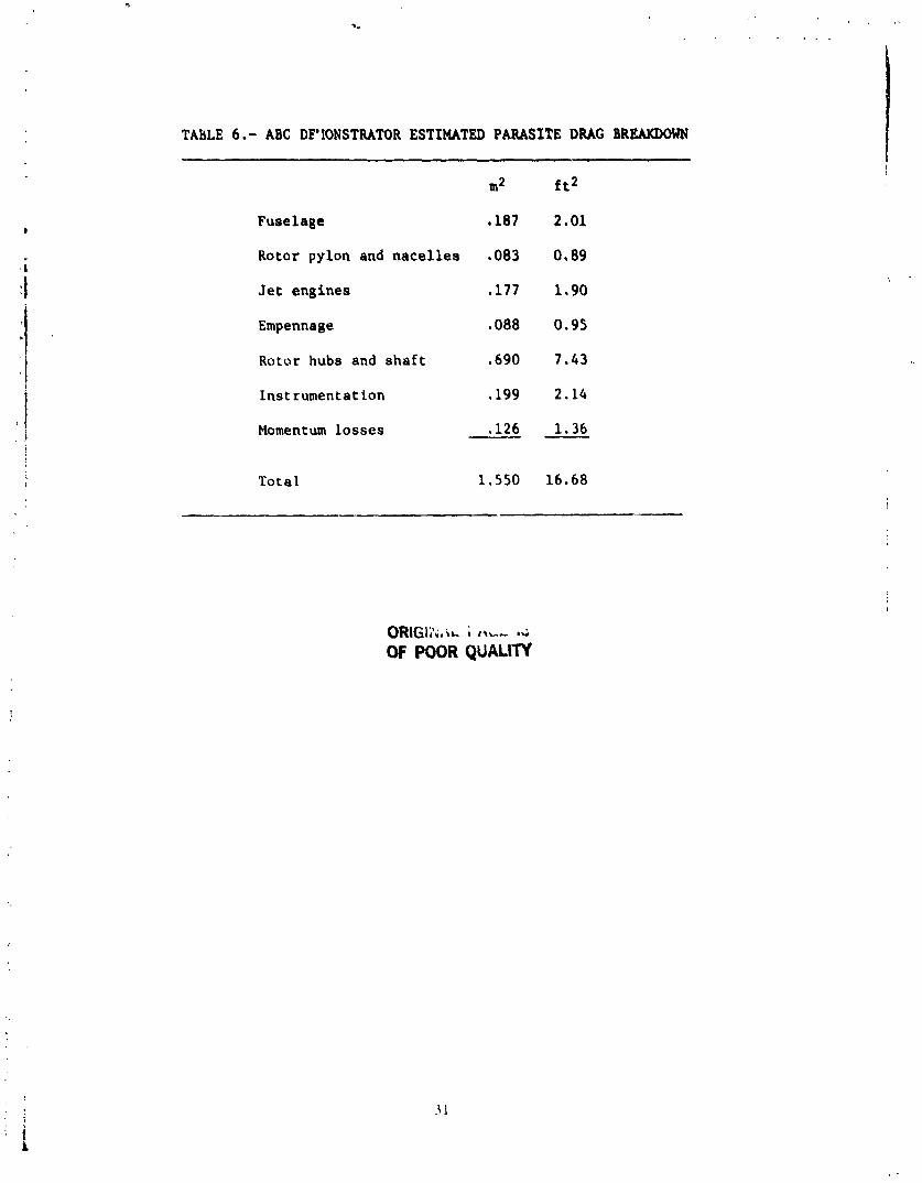
TABLE 6.- ABC DF'1ONSTRATOR ESTIMATED PARASITE D M BREAKDOWN
m2
Fuselage ,187
Rotor pylon and nacelles .083
Jet engines ,177
Empennage ,088
Rotor hubs and shaft .690
Instrumentatian ,199
Momentum losses ,126
Total 1.550 16.68
QRIGI;';/w. i ,t.-- L
OF POOR QUALITY
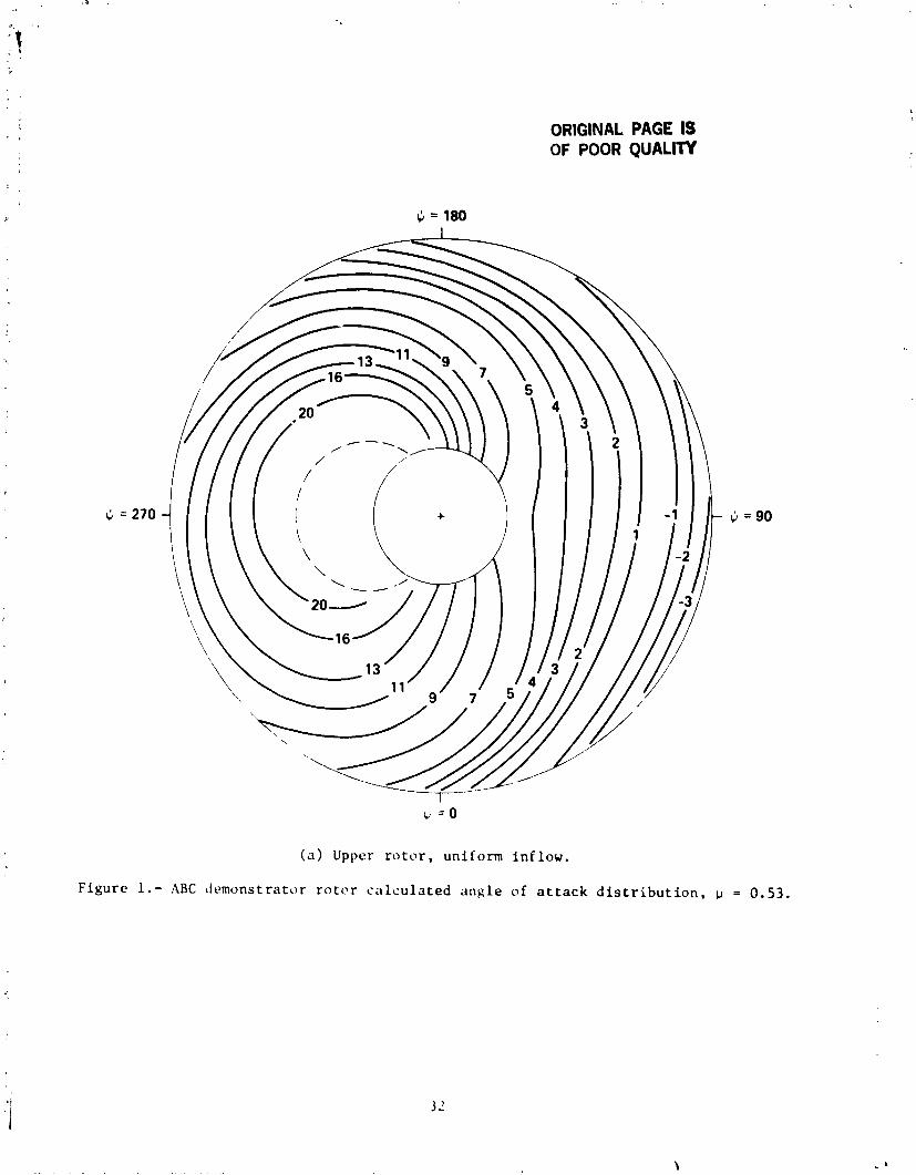
ORIGINAL PAGE IS OF POOR QUALITY
( a ) Upper r o t o r , un i form i n f l o w .
F igu re 1.- ABC ~ i e m o n s t r a t o r r o t c r c a l c u l a t e d a n g l e of a t t a c k d i s t r i b u t i o n , u = 0.53.
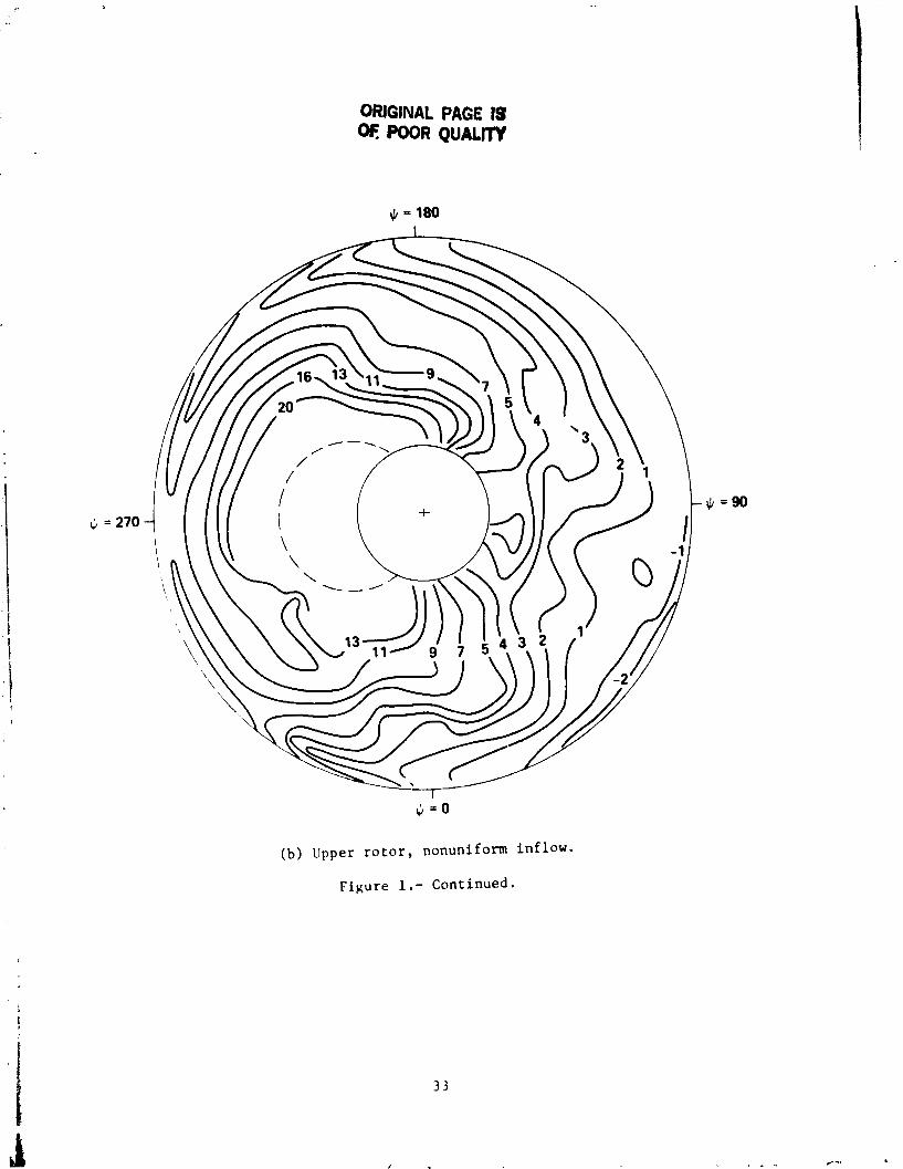
ORIGINAL PAGE I$ oE POOR QUALIN
( b ) Upper rotor, nonuniform inflow.
Figure 1.- Continued.
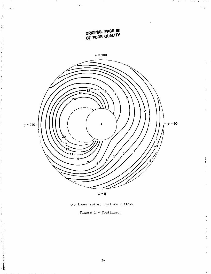
( c ) Lower rotor, uniform inflow.
Figure 1.- Continued.
ORIGINAL PAGE IS OF POOR QUALIW
ORIGINAL PAGE IS OF POOR QUALIN
- ABC DEMO (REF. 6) - - - JVX -- - -- WINDTUNNEL TEST ROTOR
(REF. 5) + 4 r
ORIGINAL FAGE IS OF POOR QUALIW
Figure i . ARC dcmo~~strator trim a t t i t * ~ d e r .
ORIGINAL PAGE IS
FLIGHT TEST DATA OF POOR QUAUTY
CALCULATION - Bi = 2", VARYING TRIM CONDlT IONS
SIKORSKY AIRCRAFT TRENDS O76 B\
4,3
3 , 3
2.3 1,3
L I 1 1 1
0 .2 .4 .6 .8 ADVANCE RATIO
Figure 5.- ABC demonstrator rotor lift offset.
TEST
CL/il Bi
0 0.10 2 CALCULATED 0 0.12 2
- - - cL/n = O.IC), Bi = 2 ' 0 0.10 8 - . - CL/tr = 0.12, Bi = 2' A 0.12 8
-.. - cL/o =O. IO,Bi=8' D 0.16 8 10 - -- --- - .- --- -\
8 - 4"
at e A
8"
Figis 6.- Wind tunnel test correlation, u = 0.47.
ORIGINAL PAGE (3 Of POOR QLIALIW
CL/0 Bi
0 0.10 2 0 0.12 2 0 0 . 1 6 2 A 0.18 2 + SYMBOLS ARE Bi - 6 - SYMBOLS ARE Bi = 8
CALCULATION
Figure 7 . - Wind tunnel t e s t corre la t ion , IJ = 0 . 7 0 .
TEST
--- CALCULATED
Fjgure 8 . - Wind tunnel test corre la t ion , P = 0 . 9 1 .
0.12 2 0.16 2 0.18 2 SYMBOLS ARE
SYMBOLS ARE TEST
I - - - CALCULATED, n , * O '
-. - CALCULATED, - 4"
2 I 1 I I I I 1
0 .OM .008 .012 ,016 .020 ,024 ,028 C,,lll
ORIGINAL PAGE IS OF POOR C)'.'/\' ITY
TEST
&- 0- -A CALCULATION
Figure 11. - Wind tunnel t e s t c o r r e l a t i o n , u = 0.91 .
ABC DEMO
- - -- ADVANCED ABC /
.12 /
2 0
\ 0
520 140 160 180 200 220 240 260 V, knots
FLP- re 12.- AH(: rotor operating condi t ions .
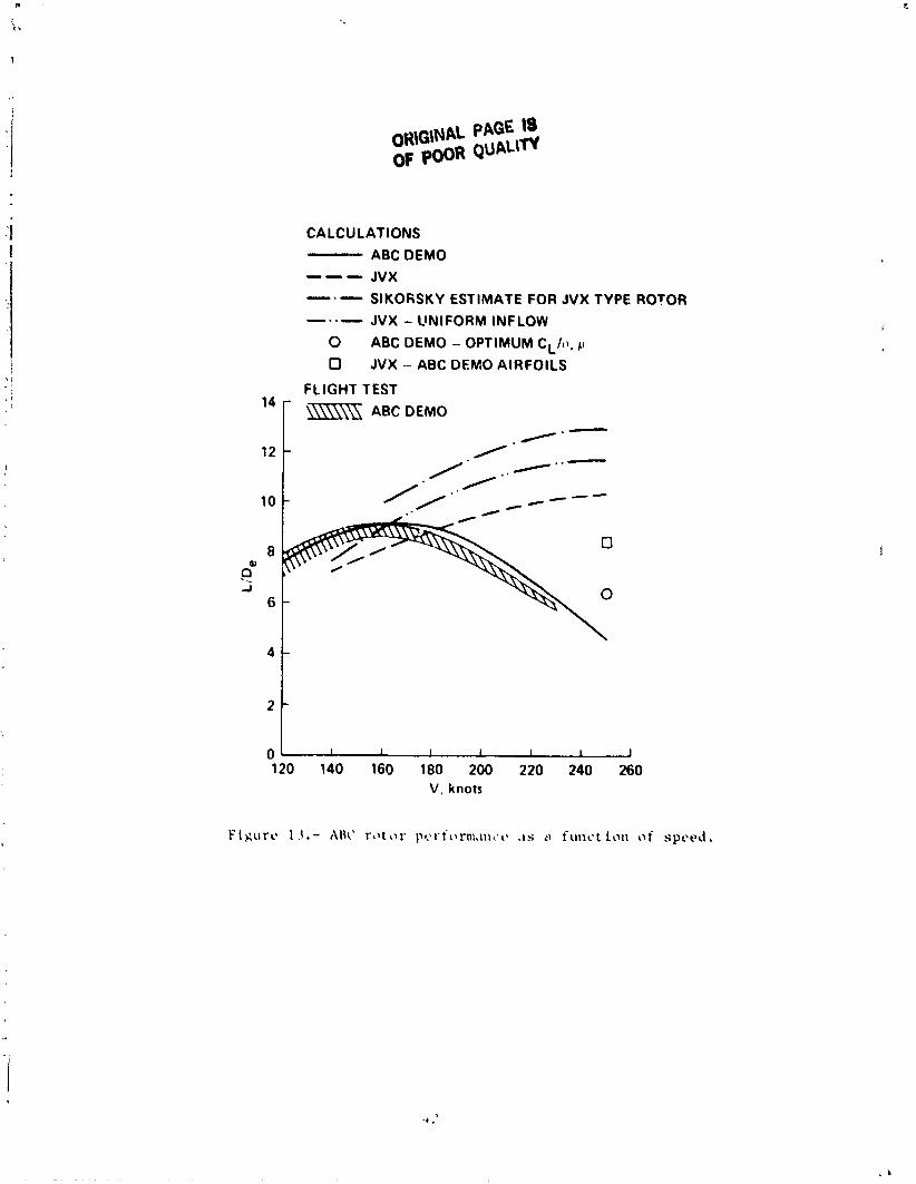
CALCULATIONS
ABC DEMO --- JVX -.- SlKOFiSKY ESTIMATE FOR JVX TYPE ROTOR
-..- JVX - UNIFORM INFLOW
0 ABC DEMO - OPTIMUM CL/t1. p
0 JVX - ABC DEMO AIRFOILS
FLIGHT TEST
120 140 160 180 200 220 240 260 V, knots
ORIGINAL FAGE IS OF POOR QUALITY
ABC DEMO --- JVX -.- SIKORSKY ESTIMATE FOR JVX TYPE ROTOR -..- JVX - UNIFORM INFLOW - ... - JVX - ABC DEMO AIRFOILS
Figure 14.- ABC rotor performance as a function of lift at u = 0.85, MT = 0.85, as = 0.
ORIGINAL PAGE IS OF POOR QUALITY '
Figure 15.- Advanced ABC r o t o r performance a t p = 0.47 and p = 0.85 (MT = 0.85, as 0, B i = 2 " ) .
Figure 16 . - E f f e c t o f t w i s t on advanced ABC r o t o r performance ( P = 0.85, MT = 0.85, as = 0 , B; = 2 ' ) .
ORIGINAL PAGE IS OF POOR QUALITY
FLIGHT TEST CALCULATIONS
El* - SIKORSKY DATA FAIRING 0 0 --- CCHAP 0 1.5 -.- A7906
0 0 0 0
Figure 18 . - XBC demons:rator i s o l a t e d rotor hover performance.
ORIGINAL PAGE IS OF POOR QUALlfV
- CCHAP -0- A7908
Figure 19.- Calculated isolated rotor hover performance for advanced ABC rotor design.
ABC DEMO (FLIGHT TEST FAIRING) ABC ADVANCED ROTOR (SIKORSKY) JVX ESTIMATE (A79061
ORIGINAL PAGE fS POOR QUAilW
Figure 20.- Comparison of isolated rotor hover performance of ABC demonstrator and advanced ABC rotor design.
0 20 40 60 80 100 COLLECTIVE, %
(a) Collective rigging.
Figure 21.- ABC demonstrator aircraft control rigging.
ORIGINAL PAGE IS OF POOR QUALITY
-I2 2---., -14 I
0 20 40 60 80 100 LONGITUDINAL CONTRC,! ... ;,'
( b ) Average longitudinal r igg ing .
Figure 21.- Continued.
-14 -I2 0 2 20 40 60 80 100
LONGITUDINAL CONTROL, %
( c ) L o n g i t u d i n a l r i g g i n g .
F i g u r e 21.- C o n t i n u e d .
0 20 40 60 80 100 LATERAL CONTROL, %
( d ) Average l a t e r a l rigging.
Figure 21.- Continued.
ORDINAL PAS'I;: 13 OF POOR QUALITY
LATERAL CONTROL, %
( e ) Lateral rigging.
Figure 21.- Continued.
1 1 1 I J
0 20 40 60 80 100
PEDAL, %
( f ) Differential collective rigging.
Figure 21.- Continued.
I 1 1
-100 -50 0 5 0 100 Ai ACTUATOR, %
(8) Differential longitudinal rigging.
f Figure 21.- Continued.
-1 1 1 I 1 1 J 0 20 40 60 80 100
8i ACTUATOR, %
,.,) Differential lateral r igg ing .
I:i~t:rt* ?1 .- Cant inut'd.
ORIGINAL FA,"':. Is, OF POOR QUALII Y
DIFFERENTIAL COLLECTIVE, %
t i ) Differential collective trim rigging.
Figure 2 1 . - Continued.
0 20 40 60 80 100 PEDAL POSITION, %
(.i ? Rudder r i g g i n g .
O R M A L PAGE I8 OF POOR QUALm
- XH-59 WITH INSTRUMENTATION CAN - XH-59 - NO INSTRUMENTATION 2.0 r
1:igurc 1 2 . - ABC drag variation with angle-of-at tack (wind tunnel test r e s u l t s , from reference 10).
ORIGINAL PAQE f.3 OF POOR QUALITY
0 1 2 3 4 5 6 7 1000 8HP - TRANSMISSION RATING
20
18
16
0 ABC DEMONSTRATOR (XH-S9A)
- 0 SIKORSKY HMX ESTIMATE 0 ALTERNATE HMX ESTIMATE A AH-64
- b UH-60 b POP DATA BASE
CONVENTIONAL ROTORS 0 - - - - ABC TREND /
0 0