Embed Size (px)
Citation preview
ROUGH TERRAINHYDRAULIC CRANE
• • • • • • • • • • • • • • • • • • • • •
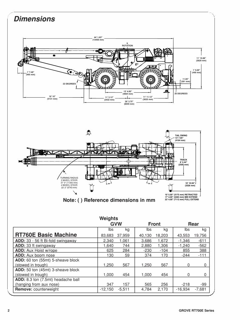
TAIL SWING13' 7.95"(4164 mm)
TRACK8' 2.44"
(2500 mm)
10' 10.94"(3326 mm)
10' 5.00" (3175 mm) RETRACTED17' 4.00" (5283 mm) MID EXTEND23' 4.00" (7112 mm) FULL EXTEND
TURNING RADIUS2 WHEEL STEER37' 3" (11342 mm)4 WHEEL STEER22' 2" (6743 mm)
44' 1.83"(13458 mm)
1' 7.49"(495 mm)
16' 10"(5131 mm)
22 DEGREES
11' 3.12"(3432 mm)
13' 4.00"(4064 mm)
26' 3.75"(8020 mm)
ROTATIONCL
11' 11.12"(3635 mm)
20 DEGREES
11.05"(281 mm)
1' 5.69"(449 mm)
11' 10.88"(3629 mm)
Note: ( ) Reference dimensions in mm
Dimensions
GROVE RT700E Series2
WeightsGVW Front Rear
lbs kg lbs kg lbs kg
RT760E Basic Machine 83,683 37,959 40,130 18,203 43,553 19,756ADD: 33 - 56 ft Bi-fold swingaway 2,340 1,061 3,686 1,672 -1,346 -611ADD: 33 ft swingaway 1,640 744 2,880 1,306 -1,240 -562ADD: Aux Hoist w/rope 625 284 -230 -104 855 388ADD: Aux boom nose 130 59 374 170 -244 -111ADD: 60 ton (55mt) 5-sheave block(stowed in trough) 1,250 567 1,250 567 0 0ADD: 50 ton (45mt) 3-sheave block(stowed in trough) 1,000 454 1,000 454 0 0ADD: 8.3 ton (7.5mt) headache ball(hanging from aux nose) 347 157 565 256 -218 -99Remove: counterweight -12,150 -5,511 4,784 2,170 -16,934 -7,681
180
170
160
150
140
130
120
110
100
90
80
70
60
50
40
30
20
10
0160 140 120 100 80 60 40 20
150 130 110 90 70 50 30 10
56'
33'
110
100
90
80
70
60
50
4036
EXT.
EXT.
78°MAX.BOOMANGLE
AXIS OFROTATION
HE
IGH
T F
RO
M G
RO
UN
D IN
FE
ET
WORKING RANGE DIAGRAM
(BOOM DEFLECTION NOT SHOWN) D6-829-101026
OPERATING RADIUS IN FEET FROM AXIS OF ROTATION
BO
OM
LE
NG
TH
AN
D E
XT
EN
SIO
N IN
FE
ET
0°
10°
70°
60°
50°
40°
30°
20°
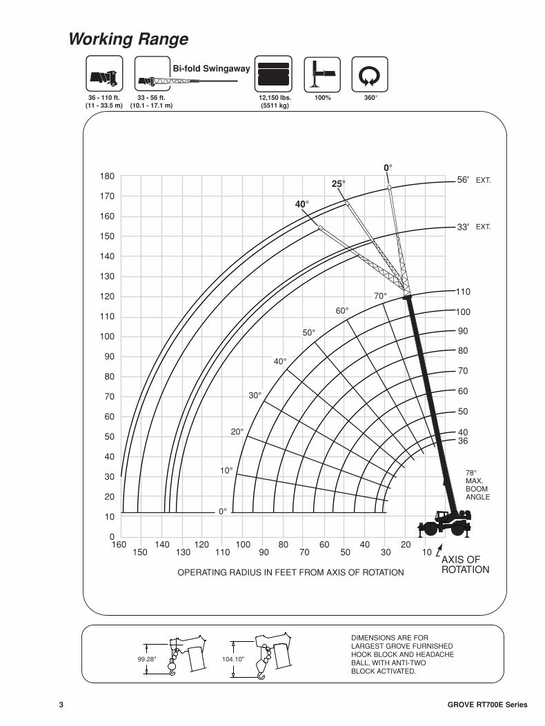
DIMENSIONS ARE FORLARGEST GROVE FURNISHEDHOOK BLOCK AND HEADACHEBALL, WITH ANTI-TWOBLOCK ACTIVATED.
99.28" 104.10"
36 - 110 ft.(11 - 33.5 m)
33 - 56 ft.(10.1 - 17.1 m)
12,150 lbs.(5511 kg)
360°100%
Bi-fold Swingaway
0°
25°
40°
GROVE RT700E Series3
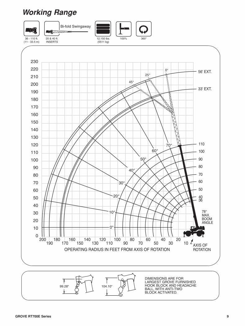
Working Range
GROVE RT700E Series4
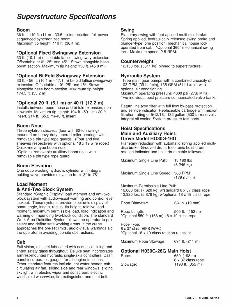
Boom36 ft. - 110 ft. (11 m - 33.5 m) four-section, full-powersequenced synchronized boom.Maximum tip height: 119 ft. (36.4 m).
*Optional Fixed Swingaway Extension33 ft. (10.1 m) offsettable lattice swingaway extension.Offsettable at 0°, 25° and 45°. Stows alongside baseboom section. Maximum tip height: 150 ft. (45.8 m).
*Optional Bi-Fold Swingaway Extension33 ft. - 56 ft. (10.1 m - 17.1 m) bi-fold lattice swingawayextension. Offsettable at 0°, 25° and 45°. Stowsalongside base boom section. Maximum tip height:174.5 ft. (53.2 m).
*Optional 20 ft. (6.1 m) or 40 ft. (12.2 m)Installs between boom nose and bi-fold extension, non-stowable. Maximum tip height: 194 ft. (59.1 m)-20 ft.insert, 214 ft. (65.2 m)-40 ft. insert.
Boom NoseThree nylatron sheaves (four with 60-ton rating)mounted on heavy-duty tapered roller bearings withremovable pin-type rope guards. (Four and fivesheaves respectively with optional 18 x 19 wire rope.)Quick-reeve type boom nose. *Optional removable auxiliary boom nose withremovable pin type rope guard.
Boom Elevation One double-acting hydraulic cylinder with integralholding valve provides elevation from -3° to 78°.
Load Moment & Anti-Two Block SystemStandard “Graphic Display” load moment and anti-twoblock system with audio-visual warning and control leverlockout. These systems provide electronic display ofboom angle, length, radius, tip height, relative loadmoment, maximum permissible load, load indication andwarning of impending two-block condition. The standardWork Area Definition System allows the operator to pre-select and define safe working areas. If the craneapproaches the pre-set limits, audio-visual warnings aidthe operator in avoiding job-site obstructions.
CabFull-vision, all-steel fabricated with acoustical lining andtinted safety glass throughout. Deluxe seat incorporatesarmrest-mounted hydraulic single-axis controllers. Dashpanel incorporates gauges for all engine functions.Other standard features include: hot water heater, cabcirculating air fan, sliding side and rear windows, slidingskylight with electric wiper and sunscreen, electricwindshield wash/wipe, fire extinguisher and seat belt.
Swing Planetary swing with foot-applied multi-disc brake.Spring applied, hydraulically-released swing brake andplunger-type, one position, mechanical house lockoperated from cab. *Optional 360° mechanical swinglock. Maximum speed: 2.5 RPM.
Counterweight 12,150 lbs. (5511 kg) pinned to superstructure.
Hydraulic System Three main gear pumps with a combined capacity of103 GPM (391 L/min), 135 GPM (511 L/min) withoptional air conditioning.Maximum operating pressure: 4000 psi (27.6 MPa).Two individual post pressure compensated valve banks.
Return line type filter with full flow by-pass protectionand service indicator. Replaceable cartridge with micronfiltration rating of 5/12/16. 132 gallon (500 L) reservoir.Integral oil cooler. System pressure test ports.
Hoist SpecificationsMain and Auxiliary Hoist:Grove Model HO30G-16GPlanetary reduction with automatic spring applied multi-disc brake. Grooved drum. Electronic hoist drumrotation indicator and hoist drum cable followers.
Maximum Single Line Pull: 18,180 lbs(8 246 kg)
Maximum Single Line Speed: 588 FPM(179 m/min)
Maximum Permissible Line Pull:16,800 lbs. (7 620 kg) w/standard 6 x 37 class rope12,920 lbs. (5 879 kg) w/optional 18 x 19 class rope
Rope Diameter: 3/4 in. (19 mm)
Rope Length: 500 ft. (152 m)*Optional 550 ft. (168 m) 18 x 19 class rope
Rope Type:6 x 37 class EIPS IWRC*Optional 18 x 19 class rotation resistant
Maximum Rope Stowage: 694 ft. (211 m)
Optional H030G-26G Main HoistRope: 650' (198 m)
6 x 37 class ropeStowage: 1193 ft. (355 m)
Superstructure Specifications
5GROVE RT700E Series
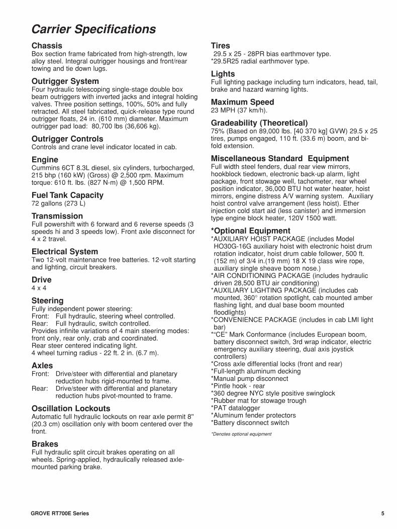
ChassisBox section frame fabricated from high-strength, lowalloy steel. Integral outrigger housings and front/reartowing and tie down lugs.
Outrigger SystemFour hydraulic telescoping single-stage double boxbeam outriggers with inverted jacks and integral holdingvalves. Three position settings, 100%, 50% and fullyretracted. All steel fabricated, quick-release type roundoutrigger floats, 24 in. (610 mm) diameter. Maximumoutrigger pad load: 80,700 lbs (36,606 kg).
Outrigger ControlsControls and crane level indicator located in cab.
EngineCummins 6CT 8.3L diesel, six cylinders, turbocharged,215 bhp (160 kW) (Gross) @ 2,500 rpm. Maximumtorque: 610 ft. lbs. (827 N-m) @ 1,500 RPM.
Fuel Tank Capacity72 gallons (273 L)
TransmissionFull powershift with 6 forward and 6 reverse speeds (3speeds hi and 3 speeds low). Front axle disconnect for4 x 2 travel.
Electrical SystemTwo 12-volt maintenance free batteries. 12-volt startingand lighting, circuit breakers.
Drive4 x 4
SteeringFully independent power steering:Front: Full hydraulic, steering wheel controlled.Rear: Full hydraulic, switch controlled.Provides infinite variations of 4 main steering modes:front only, rear only, crab and coordinated. Rear steer centered indicating light.4 wheel turning radius - 22 ft. 2 in. (6.7 m).
AxlesFront: Drive/steer with differential and planetary
reduction hubs rigid-mounted to frame.Rear: Drive/steer with differential and planetary
reduction hubs pivot-mounted to frame.
Oscillation Lockouts Automatic full hydraulic lockouts on rear axle permit 8''(20.3 cm) oscillation only with boom centered over thefront.
BrakesFull hydraulic split circuit brakes operating on allwheels. Spring-applied, hydraulically released axle-mounted parking brake.
Tires*29.5 x 25 - 28PR bias earthmover type. *29.5R25 radial earthmover type.
LightsFull lighting package including turn indicators, head, tail,brake and hazard warning lights.
Maximum Speed23 MPH (37 km/h).
Gradeability (Theoretical)75% (Based on 89,000 lbs. [40 370 kg] GVW) 29.5 x 25tires, pumps engaged, 110 ft. (33.6 m) boom, and bi-fold extension.
Miscellaneous Standard EquipmentFull width steel fenders, dual rear view mirrors,hookblock tiedown, electronic back-up alarm, lightpackage, front stowage well, tachometer, rear wheelposition indicator, 36,000 BTU hot water heater, hoistmirrors, engine distress A/V warning system. Auxiliaryhoist control valve arrangement (less hoist). Etherinjection cold start aid (less canister) and immersiontype engine block heater, 120V 1500 watt.
*Optional Equipment*AUXILIARY HOIST PACKAGE (includes ModelHO30G-16G auxiliary hoist with electronic hoist drumrotation indicator, hoist drum cable follower, 500 ft.(152 m) of 3/4 in.(19 mm) 18 X 19 class wire rope,auxiliary single sheave boom nose.)
*AIR CONDITIONING PACKAGE (includes hydraulicdriven 28,500 BTU air conditioning)
*AUXILIARY LIGHTING PACKAGE (includes cabmounted, 360° rotation spotlight, cab mounted amberflashing light, and dual base boom mountedfloodlights)
*CONVENIENCE PACKAGE (includes in cab LMI lightbar)
*“CE” Mark Conformance (includes European boom,battery disconnect switch, 3rd wrap indicator, electricemergency auxiliary steering, dual axis joystickcontrollers)
*Cross axle differential locks (front and rear) *Full-length aluminum decking*Manual pump disconnect*Pintle hook - rear*360 degree NYC style positive swinglock*Rubber mat for stowage trough*PAT datalogger*Aluminum fender protectors*Battery disconnect switch
*Denotes optional equipment
Carrier Specifications
GROVE RT700E Series6
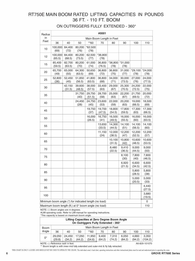
RT750E MAIN BOOM RATED LIFTING CAPACITIES IN POUNDS36 FT. - 110 FT. BOOM
ON OUTRIGGERS FULLY EXTENDED - 360°
Radiusin
Feet
#0001
Main Boom Length in Feet
36 40 50 **60 70 80 90 100 110
10100,000
(69)84,400
(72)80,200
(76)*62,500
(78)
12100,000(65.5)
84,400(68.5)
80,200(73.5)
62,500(77)
*36,800(78)
1585,400(59.5)
82,700(63.5)
80,200(70)
61,000(74)
36,800(76.5)
*36,800(78)
*31,000(78)
2065,700
(49)65,000
(55)64,300(63.5)
50,650(69)
36,800(72)
36,800(75)
31,000(77)
*29,100(78)
*24,000(78)
2552,800
(36)52,450
(45)51,850(56.5)
41,800(63.5)
36,800(68)
34,000(71)
30,000(73.5)
27,000(76)
24,000(77.5)
3042,150(31.5)
39,600(48.5)
38,000(57.5)
33,400(63)
29,000(67)
25,300(70.5)
24,200(72.5)
22,000(75)
3531,750
(40)29,750(51.5)
28,700(58)
25,000(63)
22,200(67)
21,750(69.5)
20,000(72)
4024,450
(28)24,750
(45)23,600
(53)22,000
(59)20,200
(63)19,000(66.5)
18,500(69)
45
19,750(37)
19,700(47.5)
18,800(54.5)
17,800(59.5)
17,300(63)
17,300(66.5)
5016,000(26.5)
16,750(41)
16,500(49.5)
16,000(55.5)
16,000(60)
16,000(63.5)
5513,650(33.5)
14,300(44.5)
14,100(51)
14,100(56.5)
14,100(60)
6011,150
(24)12,000(38.5)
12,200(47)
12,200(52.5)
12,200(57)
6510,100(31.5)
10,800(42)
10,600(48.5)
10,600(53.5)
708,480(22.5)
9,410(36.5)
9,000(44.5)
9,000(50)
758,100(30)
7,800(40)
7,800(46.5)
806,920(21.5)
6,600(34.5)
6,600(42.5)
855,800(28.5)
5,800(38)
905,000(20.5)
5,000(33)
954,440(27.5)
1003,880(19.5)
Minimum boom angle (°) for indicated length (no load) 0
Maximum boom length (ft.) at 0° boom angle (no load) 110NOTE: ( ) Boom angles are in degrees.#LMI operating code. Refer to LMI manual for operating instructions.*This capacity is based on maximum boom angle.
Lifting Capacities at Zero Degree Boom AngleOn Outriggers Fully Extended - 360°
BoomAngle
Main Boom Length in Feet
36 40 50 **60 70 80 90 100 110
0° 29,050(29.8)
24,450(34.2)
17,050(44.2)
11,950(54.6)
9,400(64.2)
7,310(74.2)
6,050(84.2)
4,660(94.2)
3,350(104.2)
NOTE: ( ) Reference radii in feet.** Boom length is with inner-mid fully extended and outer-mid & fly fully retracted.
A6-829-101070
THIS CHART IS ONLY A GUIDE AND SHOULD NOT BE USED TO OPERATE THE CRANE. The individual crane’s load chart, operating instructions and other instructional plates must be read and understood prior to operating the crane.
7GROVE RT700E Series
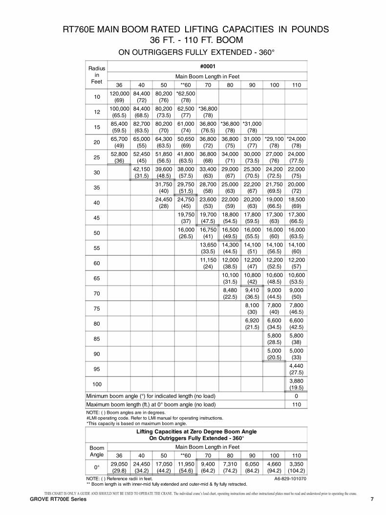
RT760E MAIN BOOM RATED LIFTING CAPACITIES IN POUNDS36 FT. - 110 FT. BOOM
ON OUTRIGGERS FULLY EXTENDED - 360°
Radiusin
Feet
#0001
Main Boom Length in Feet
36 40 50 **60 70 80 90 100 110
10120,000
(69)84,400
(72)80,200
(76)*62,500
(78)
12100,000(65.5)
84,400(68.5)
80,200(73.5)
62,500(77)
*36,800(78)
1585,400(59.5)
82,700(63.5)
80,200(70)
61,000(74)
36,800(76.5)
*36,800(78)
*31,000(78)
2065,700
(49)65,000
(55)64,300(63.5)
50,650(69)
36,800(72)
36,800(75)
31,000(77)
*29,100(78)
*24,000(78)
2552,800
(36)52,450
(45)51,850(56.5)
41,800(63.5)
36,800(68)
34,000(71)
30,000(73.5)
27,000(76)
24,000(77.5)
3042,150(31.5)
39,600(48.5)
38,000(57.5)
33,400(63)
29,000(67)
25,300(70.5)
24,200(72.5)
22,000(75)
3531,750
(40)29,750(51.5)
28,700(58)
25,000(63)
22,200(67)
21,750(69.5)
20,000(72)
4024,450
(28)24,750
(45)23,600
(53)22,000
(59)20,200
(63)19,000(66.5)
18,500(69)
4519,750
(37)19,700(47.5)
18,800(54.5)
17,800(59.5)
17,300(63)
17,300(66.5)
5016,000(26.5)
16,750(41)
16,500(49.5)
16,000(55.5)
16,000(60)
16,000(63.5)
5513,650(33.5)
14,300(44.5)
14,100(51)
14,100(56.5)
14,100(60)
6011,150
(24)12,000(38.5)
12,200(47)
12,200(52.5)
12,200(57)
6510,100(31.5)
10,800(42)
10,600(48.5)
10,600(53.5)
708,480(22.5)
9,410(36.5)
9,000(44.5)
9,000(50)
758,100(30)
7,800(40)
7,800(46.5)
806,920(21.5)
6,600(34.5)
6,600(42.5)
855,800(28.5)
5,800(38)
905,000(20.5)
5,000(33)
954,440(27.5)
1003,880(19.5)
Minimum boom angle (°) for indicated length (no load) 0
Maximum boom length (ft.) at 0° boom angle (no load) 110NOTE: ( ) Boom angles are in degrees.#LMI operating code. Refer to LMI manual for operating instructions.*This capacity is based on maximum boom angle.
Lifting Capacities at Zero Degree Boom AngleOn Outriggers Fully Extended - 360°
BoomAngle
Main Boom Length in Feet
36 40 50 **60 70 80 90 100 110
0° 29,050(29.8)
24,450(34.2)
17,050(44.2)
11,950(54.6)
9,400(64.2)
7,310(74.2)
6,050(84.2)
4,660(94.2)
3,350(104.2)
NOTE: ( ) Reference radii in feet.** Boom length is with inner-mid fully extended and outer-mid & fly fully retracted.
A6-829-101070
THIS CHART IS ONLY A GUIDE AND SHOULD NOT BE USED TO OPERATE THE CRANE. The individual crane’s load chart, operating instructions and other instructional plates must be read and understood prior to operating the crane.
GROVE RT700E Series8
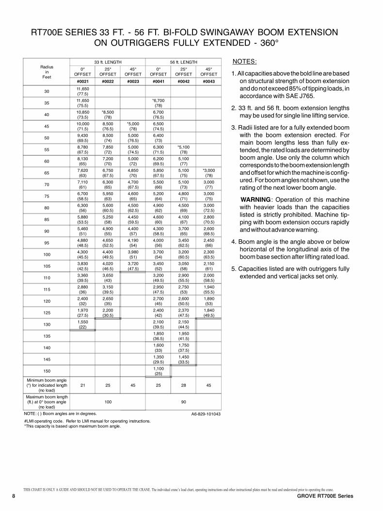
RT700E SERIES 33 FT. - 56 FT. BOOM EXTENSION
ON OUTRIGGERS FULLY EXTENDED - 360¡
NOTES:
1.All capacitiesabovethebold linearebased
on structural strength of boom extension
anddonotexceed85%of tipping loads, in
accordance with SAE J765.
2. 33 ft. and 56 ft. boom extension lengths
may be used for single line lifting service.
3. Radii listed are for a fully extended boom
with the boom extension erected. For
main boom lengths less than fully ex-
tended, the rated loadsaredeterminedby
boom angle. Use only the column which
correspondsto theboomextension length
andoffset forwhich themachine isconfig-
ured.Forboomanglesnotshown,use the
rating of the next lower boom angle.
WARNING: Operation of this machine
with heavier loads than the capacities
listed is strictly prohibited. Machine tip-
ping with boom extension occurs rapidly
andwithoutadvancewarning.
4. Boom angle is the angle above or below
horizontal of the longitudinal axis of the
boombasesectionafter lifting rated load.
5. Capacities listed are with outriggers fully
extended and vertical jacks set only.
Radius
in
Feet
33 ft. LENGTH 56 ft. LENGTH
0¡
OFFSET
25¡
OFFSET
45¡
OFFSET
0¡
OFFSET
25¡
OFFSET
45¡
OFFSET
#0021 #0022 #0023 #0041 #0042 #0043
3011,650
(77.5)
3511,650
(75.5)
*6,700
(78)
4010,850
(73.5)
*8,500
(78)
6,700
(76.5)
4510,000
(71.5)
8,500
(76.5)
*5,000
(78)
6,500
(74.5)
509,430
(69.5)
8,500
(74)
5,000
(76.5)
6,400
(73)
558,780
(67.5)
7,850
(72)
5,000
(74.5)
6,300
(71.5)
*5,100
(78)
608,130
(65)
7,200
(70)
5,000
(72)
6,200
(69.5)
5,100
(77)
657,620
(63)
6,750
(67.5)
4,850
(70)
5,850
(67.5)
5,100
(75)
*3,000
(78)
707,110
(61)
6,300
(65)
4,700
(67.5)
5,500
(66)
5,100
(73)
3,000
(77)
756,700
(58.5)
5,950
(63)
4,600
(65)
5,200
(64)
4,800
(71)
3,000
(75)
806,300
(56)
5,600
(60.5)
4,500
(62.5)
4,900
(62)
4,500
(69)
3,000
(72.5)
855,880
(53.5)
5,250
(58)
4,450
(59.5)
4,600
(60)
4,100
(67)
2,800
(70.5)
905,460
(51)
4,900
(55)
4,400
(57)
4,300
(58.5)
3,700
(65)
2,600
(68.5)
954,880
(48.5)
4,650
(52.5)
4,190
(54)
4,000
(56)
3,450
(62.5)
2,450
(66)
1004,300
(45.5)
4,400
(49.5)
3,980
(51)
3,700
(54)
3,200
(60.5)
2,300
(63.5)
1053,830
(42.5)
4,020
(46.5)
3,720
(47.5)
3,450
(52)
3,050
(58)
2,150
(61)
1103,360
(39.5)
3,650
(43)
3,200
(49.5)
2,900
(55.5)
2,000
(58.5)
1152,880
(36)
3,150
(39.5)
2,950
(47.5)
2,750
(53)
1,940
(55.5)
1202,400
(32)
2,650
(35)
2,700
(45)
2,600
(50.5)
1,890
(53)
1251,970
(27.5)
2,200
(30.5)
2,400
(42)
2,370
(47.5)
1,840
(49.5)
1301,550
(22)
2,100
(39.5)
2,150
(44.5)
1351,850
(36.5)
1,950
(41.5)
1401,600
(33)
1,750
(37.5)
1451,350
(29.5)
1,450
(33.5)
1501,100
(25)
Minimum boom angle
(¡) for indicated length
(no load)
21 25 45 25 28 45
Maximum boom length
(ft.) at 0¡ boom angle
(no load)
100 90
NOTE: ( ) Boom angles are in degrees. A6-829-101043
#LMI operating code. Refer to LMI manual for operating instructions.
*This capacity is based upon maximum boom angle.
BI-FOLD SWINGAWAY
THIS CHART IS ONLY A GUIDE AND SHOULD NOT BE USED TO OPERATE THE CRANE. The individual crane’s load chart, operating instructions and other instructional plates must be read and understood prior to operating the crane.
GROVE RT700E Series 9
230
220
210
200
190
180
170
160
150
140
130
120
110
100
90
80
70
60
50
40
30
20
10
0200 180 160 140 120 100 80 60 40 20
190 170 150 130 110 90 70 50 30 10
56' EXT.
33' EXT.
110
100
90
80
70
60
50
4036
78°MAX.BOOMANGLE
AXIS OFROTATIONOPERATING RADIUS IN FEET FROM AXIS OF ROTATION
DIMENSIONS ARE FORLARGEST GROVE FURNISHEDHOOK BLOCK AND HEADACHEBALL, WITH ANTI-TWOBLOCK ACTIVATED.
99.28" 104.10"
45°
25°0°
0°
10°
20°
30°
40°
50°
60°70°
36 - 110 ft.(11 - 33.5 m)
20 & 40 ft.INSERTS
12,150 lbs.(5511 kg)
360°100%
Bi-fold Swingaway
Working Range
10 GROVE RT700E Series
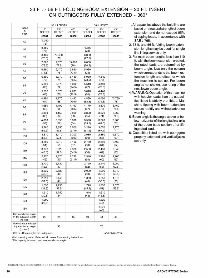
33 FT. - 56 FT. FOLDING BOOM EXTENSION + 20 FT. INSERTON OUTRIGGERS FULLY EXTENDED - 360°
1. All capacities above the bold line arebased on structural strength of boomextension and do not exceed 85%of tipping loads, in accordance withSAE J-765.
2. 33 ft. and 56 ft. folding boom exten-sion lengths may be used for singleline lifting service only.
3. For main boom lengths less than 110ft. with the boom extension erected,the rated loads are determined byboom angle. Use only the columnwhich corresponds to the boom ex-tension length and offset for whichthe machine is set up. For boomangles not shown, use rating of thenext lower boom angle.
4. WARNING: Operation of this machinewith heavier loads than the capaci-ties listed is strictly prohibited. Ma-chine tipping with boom extensionoccurs rapidly and without advancewarning.
5. Boom angle is the angle above or be-low horizontal of the longitudinal axisof the boom base section after lift-ing rated load.
6. Capacities listed are with outriggersproperly extended and vertical jacksset only.
Radiusin
Feet
33 ft. LENGTH 56 ft. LENGTH
0°OFFSET
25°OFFSET
45°OFFSET
0°OFFSET
25°OFFSET
45°OFFSET
#0064 #0065 #0066 #0084 #0085 #0086
35*9,360
(78)
409,360(77)
*6,300(78)
458,480(75.5)
*7,480(78)
6,300(77.5)
507,680(73.5)
7,070(77.5)
*5,880(78)
6,000(76.5)
556,990(71.5)
6,470(76)
5,880(77.5)
5,990(75)
606,390(70)
5,970(74)
5,480(76.5)
5,980(73.5)
*4,840(78)
655,890(68)
5,570(72)
5,080(74.5)
5,510(72)
4,840(77.5)
705,390(66)
5,070(70)
4,780(72.5)
5,010(70)
4,440(76.5)
754,990(64)
4,770(68)
4,480(70.5)
4,560(68.5)
4,050(74.5)
*3,760(78)
804,650(62)
4,400(66)
4,190(68.5)
4,170(67)
3,870(73)
3,460(76.5)
854,300(60)
4,150(64)
3,890(66)
3,820(65)
3,570(71)
3,260(74.5)
904,000(58)
3,850(62)
3,690(64)
3,520(63.5)
3,320(69.5)
2,960(73)
953,760(55.5)
3,650(59.5)
3,500(61.5)
3,220(61.5)
3,070(67.5)
2,770(71)
1003,510(53.5)
3,410(57.5)
3,300(59.5)
2,980(60)
2,880(66)
2,570(69)
1053,260(51)
3,210(55)
3,100(57)
2,780(58)
2,680(64)
2,460(67)
1103,070(48.5)
3,020(52.5)
2,930(54.5)
2,530(56)
2,480(62)
2,340(65)
1152,870(46)
2,870(50)
2,780(51.5)
2,340(54)
2,280(60)
2,200(63)
1202,730(43.5)
2,730(47)
2,190(52)
2,140(58)
2,050(60.5)
1252,530(40.5)
2,580(44)
2,000(50)
1,990(55.5)
1,910(58.5)
1302,210(37.5)
2,440(41)
1,850(48)
1,850(53.5)
1,810(56)
1351,850(34.5)
2,150(37.5)
1,720(45.5)
1,750(51)
1,670(53.5)
1401,510(30.5)
1,750(34)
1,610(43)
1,610(48.5)
1451,200(26.5)
1,520(46)
1501,370(43)
Minimum boom angle(°) for indicated length
(no load)20 25 45 40 41 45
Maximum boom length(ft.) at 0° boom angle
(no load)90 70
NOTE: ( ) Boom angles are in degrees. A6-829-101371A
#LMI operating code. Refer to LMI manual for operating instructions.*This capacity is based upon maximum boom angle.
THIS CHART IS ONLY A GUIDE AND SHOULD NOT BE USED TO OPERATE THE CRANE. The individual crane’s load chart, operating instructions and other instructional plates must be read and understood prior to operating the crane.

GROVE RT700E Series 11
THIS CHART IS ONLY A GUIDE AND SHOULD NOT BE USED TO OPERATE THE CRANE. The individual crane’s load chart, operating instructions and other instructional plates must be read and understood prior to operating the crane.
33 FT. - 56 FT. FOLDING BOOM EXTENSION + 40 FT. INSERTON OUTRIGGERS FULLY EXTENDED - 360°
1. All capacities above the bold line arebased on structural strength of boomextension and do not exceed 85%of tipping loads, in accordance withSAE J-765.
2. 33 ft. and 56 ft. folding boom exten-sion lengths may be used for singleline lifting service only.
3. For main boom lengths less than 110ft. with the boom extension erected,the rated loads are determined byboom angle. Use only the columnwhich corresponds to the boom ex-tension length and offset for whichthe machine is set up. For boomangles not shown, use rating of thenext lower boom angle.
4. WARNING: Operation of this machinewith heavier loads than the capaci-ties listed is strictly prohibited. Ma-chine tipping with boom extensionoccurs rapidly and without advancewarning.
5. Boom angle is the angle above or be-low horizontal of the longitudinal axisof the boom base section after lift-ing rated load.
6. Capacities listed are with outriggersproperly extended and vertical jacksset only.
Radiusin
Feet
33 ft. LENGTH 56 ft. LENGTH
#0064 #0065 #0066 #0084 #0085 #0086
0°OFFSET
25°OFFSET
45°OFFSET
0°OFFSET
25°OFFSET
45°OFFSET
456,560(78)
505,960(76)
4,510(78)
555,360(74.5)
5,860(78)
4,210(77.5)
604,860(73)
5,260(76.5)
*5,170(78)
3,910(76)
654,370(71)
4,870(75)
4,670(77.5)
3,710(74.5)
703,970(69.5)
4,370(73)
4,270(75.5)
3,410(73)
*3,710(78)
753,670(67.5)
4,070(71.5)
3,980(73.5)
3,220(71.5)
3,420(77.5)
803,270(66)
3,670(69.5)
3,680(72)
2,820(70)
3,120(76)
852,980(64)
3,370(68)
3,380(70)
2,520(68.5)
2,820(74.5)
2,730(77.5)
902,780(62.5)
3,080(66)
3,080(68)
2,320(66.5)
2,620(72.5)
2,530(76)
952,480(60.5)
2,880(64)
2,890(66)
2,030(65)
2,330(71)
2,340(74.5)
1002,290(58.5)
2,580(62)
2,690(64)
1,830(63.5)
2,130(69.5)
2,140(72.5)
1052,090(56.5)
2,390(60)
2,390(62)
1,630(62)
1,930(68)
1,940(71)
1101,900(54.5)
2,190(58)
2,200(60)
1,440(60)
1,730(66)
1,740(69)
1151,700(52.5)
2,000(56)
2,100(58)
1,240(58.5)
1,540(64.5)
1,550(67)
1201,600(50.5)
1,800(54)
1,910(55.5)
1,140(57)
1,340(62.5)
1,450(65)
1251,410(48)
1,700(51.5)
1,710(53)
1,240(61)
1,260(63.5)
1301,310(46)
1,510(49.5)
1,520(50.5)
1,050(59)
1,160(61.5)
1351,120(43.5)
1,420(47)
1,420(48)
1401,030(41)
1,220(44.5)
1451,130(41.5)
1501,040(38.5)
No Load Stability Data
Min. boomangle at 110'boom length
37° 37° 45° 54° 56° 58°
Max. boomlength at 0°boom angle
70 ft. 40 ft.
NOTE: ( ) Boom angles are in degrees. A6-829-101581
*This capacity is based upon maximum boom angle.
#LMI operating code. Refer to LMI manual for instructions.
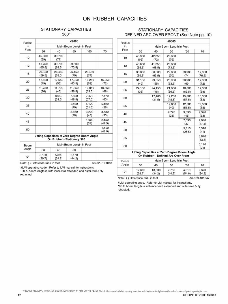
ON RUBBER CAPACITIES
STATIONARY CAPACITIES STATIONARY CAPACITIES
DEFINED ARC OVER FRONT (See Note pg. 10)
Radiusin
Feet
#9005
Main Boom Length in Feet
36 40 50 *60 70
1045,300(69)
39,700(72)
1241,750(65.5)
39,700(68.5)
29,600(73.5)
1529,350(59.5)
26,450(63.5)
26,450(70)
26,450(74)
2017,800(49)
17,650(55)
17,050(63.5)
16,250(69)
16,250(72)
2511,750(36)
11,700(45)
11,350(56.5)
10,850(63.5)
10,850(68)
308,040(31.5)
7,820(48.5)
7,470(57.5)
7,470(63)
355,400(40)
5,120(51.5)
5,120(58)
403,660(28)
3,200(45)
3,430(53)
451,000(37)
2,150(47.5)
501,150(41.0)
Lifting Capacities at Zero Degree Boom Angle
On Rubber - Stationary 360
BoomAngle
Main Boom Length in Feet
36 40 50
8,180(29.7)
5,890(34.2)
2,170(44.2)
Note: ( ) Reference radii in feet. A6-829-101048
#LMI operating code. Refer to LMI manual for instructions.*60 ft. boom length is with inner-mid extended and outer-mid & flyretracted.
Radius
inFeet
#9005
Main Boom Length in Feet
36 40 50 *60 70
1045,300(69)
42,850(72)
29,600(76)
1243,650(65.5)
41,350(68.5)
29,600(73.5)
1538,300(59.5)
36,300(63.5)
29,600(70)
20,900(74)
17,300(76.5)
2031,150
(49)
29,550
(55)
25,900
(63.5)
20,900
(69)
17,300
(72)
2524,100(36)
24,150(45)
21,800(56.5)
18,800(63.5)
17,300(68)
3017,400(31.5)
17,200(48.5)
15,300(57.5)
15,300(63)
3512,800(40)
12,500(51.5)
11,000(58)
409,720(28)
9,390(45)
9,390(53)
457,090
(37)
7,090
(47.5)
505,310(26.5)
5,310(41)
553,870(33.5)
603,170(24)
Lifting Capacities at Zero Degree Boom Angle
On Rubber - Defined Arc Over Front
Boom
Angle
Main Boom Length in Feet
36 40 50 *60 70
17,600(29.7)
13,600(34.2)
7,750(44.2)
4,010(54.6)
2,670(64.2)
Note: ( ) Reference radii in feet. A6-829-101047
#LMI operating code. Refer to LMI manual for instructions.*60 ft. boom length is with inner-mid extended and outer-mid & flyretracted.
THIS CHART IS ONLY A GUIDE AND SHOULD NOT BE USED TO OPERATE THE CRANE. The individual crane’s load chart, operating instructions and other instructional plates must be read and understood prior to operating the crane.
12 GROVE RT700E Series
13GROVE RT700E Series
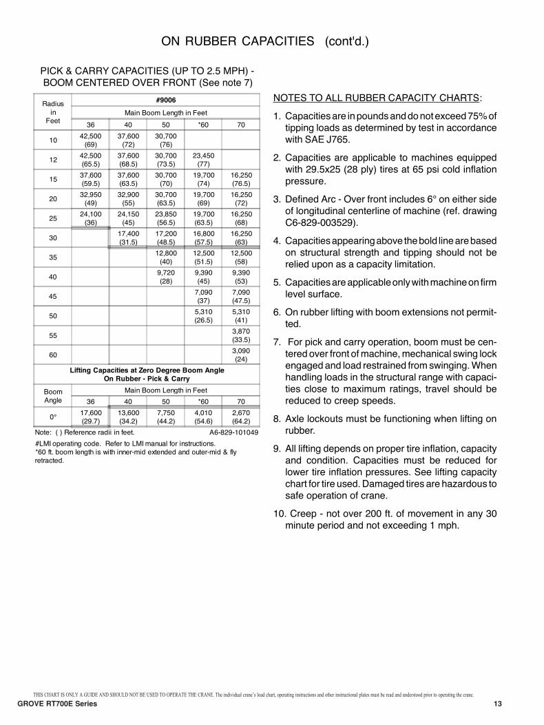
ON RUBBER CAPACITIES (cont'd.)
PICK & CARRY CAPACITIES (UP TO 2.5 MPH) -
BOOM CENTERED OVER FRONT (See note 7)
NOTES TO ALL RUBBER CAPACITY CHARTS:
1. Capacitiesare inpoundsanddonotexceed75%of
tipping loads as determined by test in accordance
with SAE J765.
2. Capacities are applicable to machines equipped
with 29.5x25 (28 ply) tires at 65 psi cold inflation
pressure.
3. Defined Arc - Over front includes 6¡ on either side
of longitudinal centerline of machine (ref. drawing
C6-829-003529).
4. Capacitiesappearingabove thebold linearebased
on structural strength and tipping should not be
relied upon as a capacity limitation.
5. Capacitiesareapplicableonlywithmachineon firm
level surface.
6. On rubber lifting with boom extensions not permit-
ted.
7. For pick and carry operation, boom must be cen-
tered over front ofmachine,mechanical swing lock
engagedand load restrained fromswinging.When
handling loads in the structural range with capaci-
ties close to maximum ratings, travel should be
reduced to creep speeds.
8. Axle lockouts must be functioning when lifting on
rubber.
9. All lifting depends on proper tire inflation, capacity
and condition. Capacities must be reduced for
lower tire inflation pressures. See lifting capacity
chart for tire used.Damaged tires are hazardous to
safe operation of crane.
10. Creep - not over 200 ft. of movement in any 30
minute period and not exceeding 1 mph.
Radius
inFeet
#9006
Main Boom Length in Feet
36 40 50 *60 70
1042,500(69)
37,600(72)
30,700(76)
1242,500(65.5)
37,600(68.5)
30,700(73.5)
23,450(77)
1537,600(59.5)
37,600(63.5)
30,700(70)
19,700(74)
16,250(76.5)
2032,950(49)
32,900(55)
30,700(63.5)
19,700(69)
16,250(72)
2524,100(36)
24,150(45)
23,850(56.5)
19,700(63.5)
16,250(68)
3017,400
(31.5)
17,200
(48.5)
16,800
(57.5)
16,250
(63)
3512,800
(40)
12,500
(51.5)
12,500
(58)
409,720
(28)
9,390
(45)
9,390
(53)
457,090(37)
7,090(47.5)
505,310(26.5)
5,310(41)
553,870(33.5)
603,090(24)
Lifting Capacities at Zero Degree Boom Angle
On Rubber - Pick & Carry
BoomAngle
Main Boom Length in Feet
36 40 50 *60 70
0¡17,600(29.7)
13,600(34.2)
7,750(44.2)
4,010(54.6)
2,670(64.2)
Note: ( ) Reference radii in feet. A6-829-101049
#LMI operating code. Refer to LMI manual for instructions.*60 ft. boom length is with inner-mid extended and outer-mid & flyretracted.
THIS CHART IS ONLY A GUIDE AND SHOULD NOT BE USED TO OPERATE THE CRANE. The individual crane’s load chart, operating instructions and other instructional plates must be read and understood prior to operating the crane.
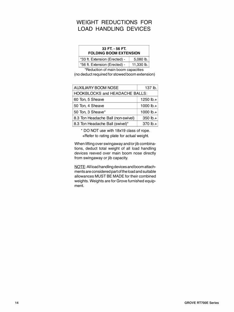
WEIGHT REDUCTIONS FOR
LOAD HANDLING DEVICES
When lifting over swingawayand/or jib combina-
tions, deduct total weight of all load handling
devices reeved over main boom nose directly
from swingaway or jib capacity.
NOTE:All loadhandlingdevicesandboomattach-
mentsareconsideredpartof the loadandsuitable
allowancesMUST BEMADE for their combined
weights.Weights are for Grove furnished equip-
ment.
33 FT. - 56 FT.
FOLDING BOOM EXTENSION
*33 ft. Extension (Erected) - 5,080 lb.
*56 ft. Extension (Erected) - 11,330 lb.
*Reduction of main boom capacities
AUXILIARYBOOM NOSE 137 lb.
HOOKBLOCKS and HEADACHE BALLS:
60 Ton, 5 Sheave 1250 lb.+
50 Ton, 4 Sheave 1000 lb.+
50 Ton, 3 Sheave* 1000 lb.+
8.3 Ton Headache Ball (non-swivel) 350 lb.+
8.3 Ton Headache Ball (swivel)* 370 lb.+
* DO NOT use with 18x19 class of rope.
+Refer to rating plate for actual weight.
(no deduct required for stowedboomextension)
14 GROVE RT700E Series
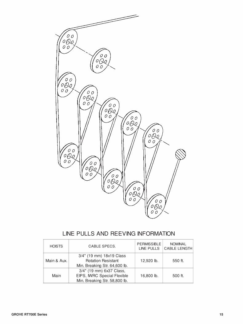
LINE PULLS AND REEVING INFORMATION
HOISTS CABLE SPECS.PERMISSIBLELINE PULLS
NOMINALCABLE LENGTH
Main & Aux.3/4" (19 mm) 18x19 Class
Rotation ResistantMin. Breaking Str. 64,600 lb.
12,920 lb. 550 ft.
Main3/4" (19 mm) 6x37 Class,
EIPS, IWRC Special FlexibleMin. Breaking Str. 58,800 lb.
16,800 lb. 500 ft.
GROVE RT700E Series 15
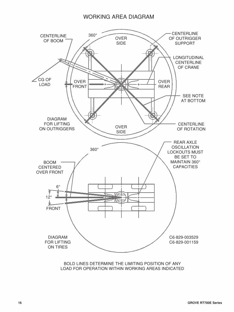
CENTERLINEOF BOOM
DIAGRAMFOR LIFTING
ON OUTRIGGERS
CENTERLINEOF OUTRIGGER
SUPPORT
LONGITUDINALCENTERLINE
OF CRANE
SEE NOTEAT BOTTOM
CENTERLINEOF ROTATION
REAR AXLEOSCILLATION
LOCKOUTS MUSTBE SET TO
MAINTAIN 360°CAPACITIES
BOOMCENTERED
OVER FRONT
DIAGRAMFOR LIFTING
ON TIRES
C6-829-003529C6-829-001159
BOLD LINES DETERMINE THE LIMITING POSITION OF ANYLOAD FOR OPERATION WITHIN WORKING AREAS INDICATED
CG OFLOAD
OVERFRONT
FRONT
OVERREAR
OVERSIDE
OVERSIDE
360°
360°
12°
6°
16 GROVE RT700E Series
WORKING AREA DIAGRAM
Form No.: RT700E Series Part No.: 3-1381 0301-4M Printed in U.S.A.
Constant improvement and engineering progress make it necessary that we reserve the right to makespecification, equipment, and price changes without notice. Illustrations shown may include optionalequipment and accessories and may not include all standard equipment.
GROVE® and GROVE LOGO are registered trademarks of GROVE in the U.S. and/or other countries.Copyright© 2000 GROVE. All rights reserved.
Grove Worldwide - World Headquarters1565 Buchanan Trail East P.O. Box 21 Shady Grove, Pennsylvania 17256-0021, U.S.A.Tel: (717) 597-8121Fax: (717) 597-4062www.groveworldwide.com
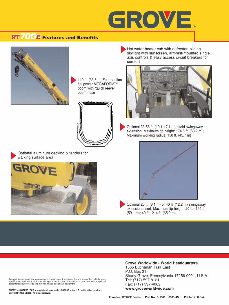
110 ft. (33.5 m) Four-sectionfull power MEGAFORM™boom with “quick reeve”boom nose
Optional aluminum decking & fenders forwalking surface area
Hot water heater cab with defroster, slidingskylight with sunscreen, armrest-mounted singleaxis controls & easy access circuit breakers forcomfort
Optional 33-56 ft. (10.1-17.1 m) bifold swingawayextension; Maximum tip height: 174.5 ft. (53.2 m);Maximum working radius: 150 ft. (45.7 m)
Optional 20 ft. (6.1 m) or 40 ft. (12.2 m) swingawayextension insert; Maximum tip height: 20 ft.--194 ft.(59.1 m); 40 ft.--214 ft. (65.2 m)
�
Features and Benefits
��
�
�