Embed Size (px)
Citation preview

Kalpakjian • SchmidManufacturing Engineering and Technology © 2001 Prentice-Hall Page 22-1
CHAPTER 22
Machining Processes Used to ProduceRound Shapes

Kalpakjian • SchmidManufacturing Engineering and Technology © 2001 Prentice-Hall Page 22-2
Cutting OperationsFigure 22.1 Variouscutting operations thatcan be performed on alate. Not that all partshave circularsymmetry.

Kalpakjian • SchmidManufacturing Engineering and Technology © 2001 Prentice-Hall Page 22-3
Components of a Lathe
Figure 22.2Components of alathe. Source:Courtesy ofHeidenreich &Harbeck
Kalpakjian • SchmidManufacturing Engineering and Technology © 2001 Prentice-Hall Page 22-4
General Characteristics of MachiningProcesses
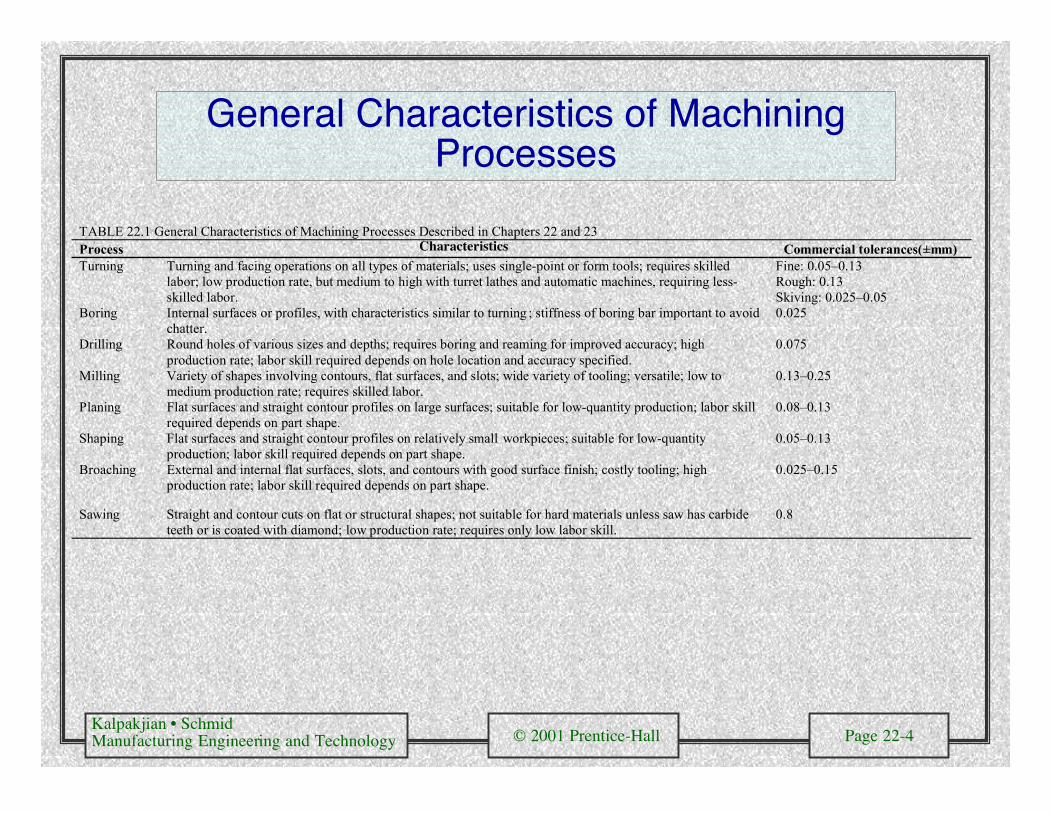
TABLE 22.1 General Characteristics of Machining Processes Described in Chapters 22 and 23Process Characteristics Commercial tolerances(±mm)Turning Turning and facing operations on all types of materials; uses single-point or form tools; requires skilled
labor; low production rate, but medium to high with turret lathes and automatic machines, requiring less-skilled labor.
Fine: 0.05–0.13Rough: 0.13Skiving: 0.025–0.05
Boring Internal surfaces or profiles, with characteristics similar to turning ; stiffness of boring bar important to avoidchatter.
0.025
Drilling Round holes of various sizes and depths; requires boring and reaming for improved accuracy; highproduction rate; labor skill required depends on hole location and accuracy specified.
0.075
Milling Variety of shapes involving contours, flat surfaces, and slots; wide variety of tooling; versatile; low tomedium production rate; requires skilled labor.
0.13–0.25
Planing Flat surfaces and straight contour profiles on large surfaces; suitable for low-quantity production; labor skillrequired depends on part shape.
0.08–0.13
Shaping Flat surfaces and straight contour profiles on relatively small workpieces; suitable for low-quantityproduction; labor skill required depends on part shape.
0.05–0.13
Broaching External and internal flat surfaces, slots, and contours with good surface finish; costly tooling; highproduction rate; labor skill required depends on part shape.
0.025–0.15
Sawing Straight and contour cuts on flat or structural shapes; not suitable for hard materials unless saw has carbideteeth or is coated with diamond; low production rate; requires only low labor skill.
0.8
Kalpakjian • SchmidManufacturing Engineering and Technology © 2001 Prentice-Hall Page 22-5
Schematic Illustration of a Turning Operation
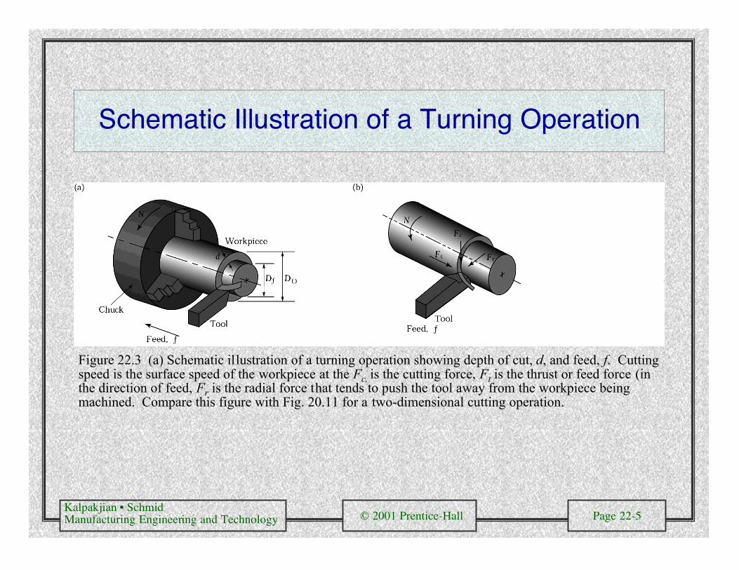
Figure 22.3 (a) Schematic illustration of a turning operation showing depth of cut, d, and feed, f. Cuttingspeed is the surface speed of the workpiece at the Fc, is the cutting force, Ft is the thrust or feed force (inthe direction of feed, Fr is the radial force that tends to push the tool away from the workpiece beingmachined. Compare this figure with Fig. 20.11 for a two-dimensional cutting operation.
Kalpakjian • SchmidManufacturing Engineering and Technology © 2001 Prentice-Hall Page 22-6
Right-HandCutting Tool
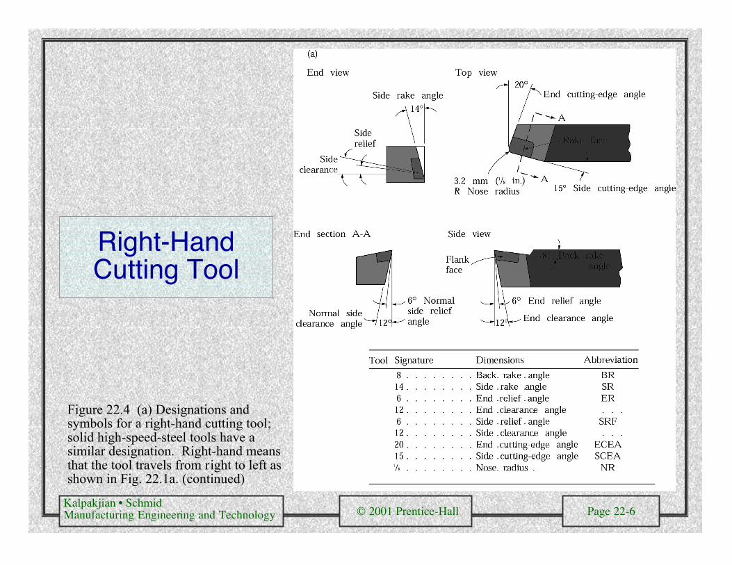
Figure 22.4 (a) Designations andsymbols for a right-hand cutting tool;solid high-speed-steel tools have asimilar designation. Right-hand meansthat the tool travels from right to left asshown in Fig. 22.1a. (continued)
Kalpakjian • SchmidManufacturing Engineering and Technology © 2001 Prentice-Hall Page 22-7
Right-Hand Cutting Tool (cont.)
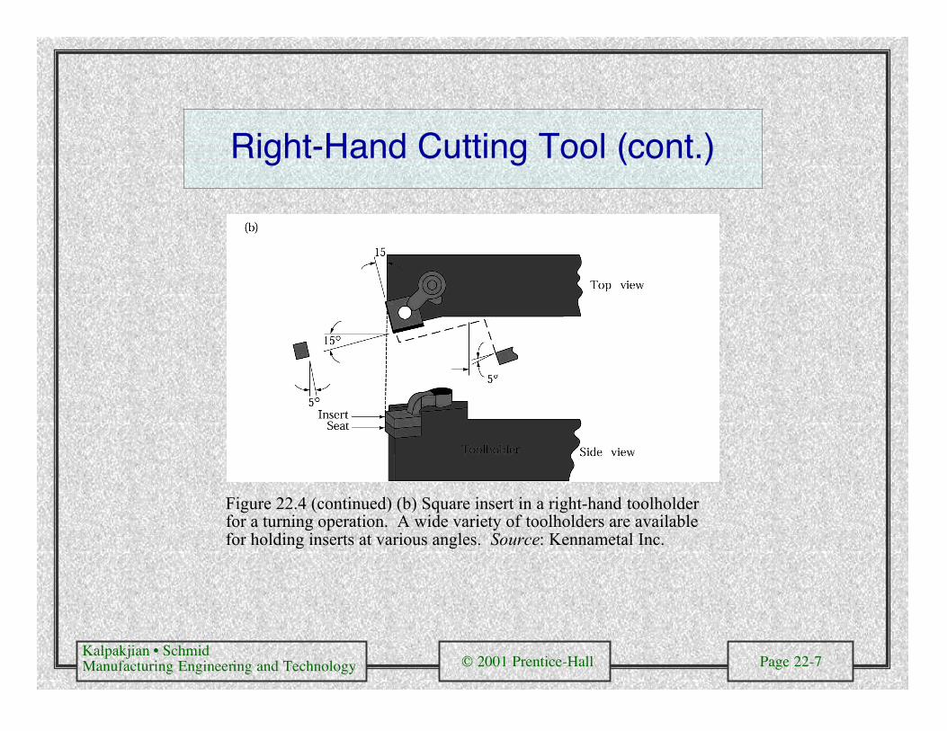
Figure 22.4 (continued) (b) Square insert in a right-hand toolholderfor a turning operation. A wide variety of toolholders are availablefor holding inserts at various angles. Source: Kennametal Inc.
Kalpakjian • SchmidManufacturing Engineering and Technology © 2001 Prentice-Hall Page 22-8
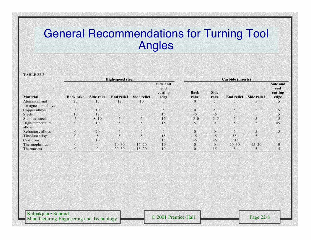
General Recommendations for Turning ToolAngles
TABLE 22.2High-speed steel Carbide (inserts)
Material Back rake Side rake End relief Side relief
Side andend
cuttingedge
Backrake
Siderake End relief Side relief
Side andend
cuttingedge
Aluminum and magnesium alloys
20 15 12 10 5 0 5 5 5 15
Copper alloys 5 10 8 8 5 0 5 5 5 15Steels 10 12 5 5 15 –5 –5 5 5 15Stainless steels 5 8–10 5 5 15 –5–0 –5–5 5 5 15High-temperaturealloys
0 10 5 5 15 5 0 5 5 45
Refractory alloys 0 20 5 5 5 0 0 5 5 15Titanium alloys 0 5 5 5 15 –5 –5 55 5Cast irons 5 10 5 5 15 –5 –5 5515Thermoplastics 0 0 20–30 15–20 10 0 0 20–30 15–20 10Thermosets 0 0 20–30 15–20 10 0 15 5 5 15
Kalpakjian • SchmidManufacturing Engineering and Technology © 2001 Prentice-Hall Page 22-9
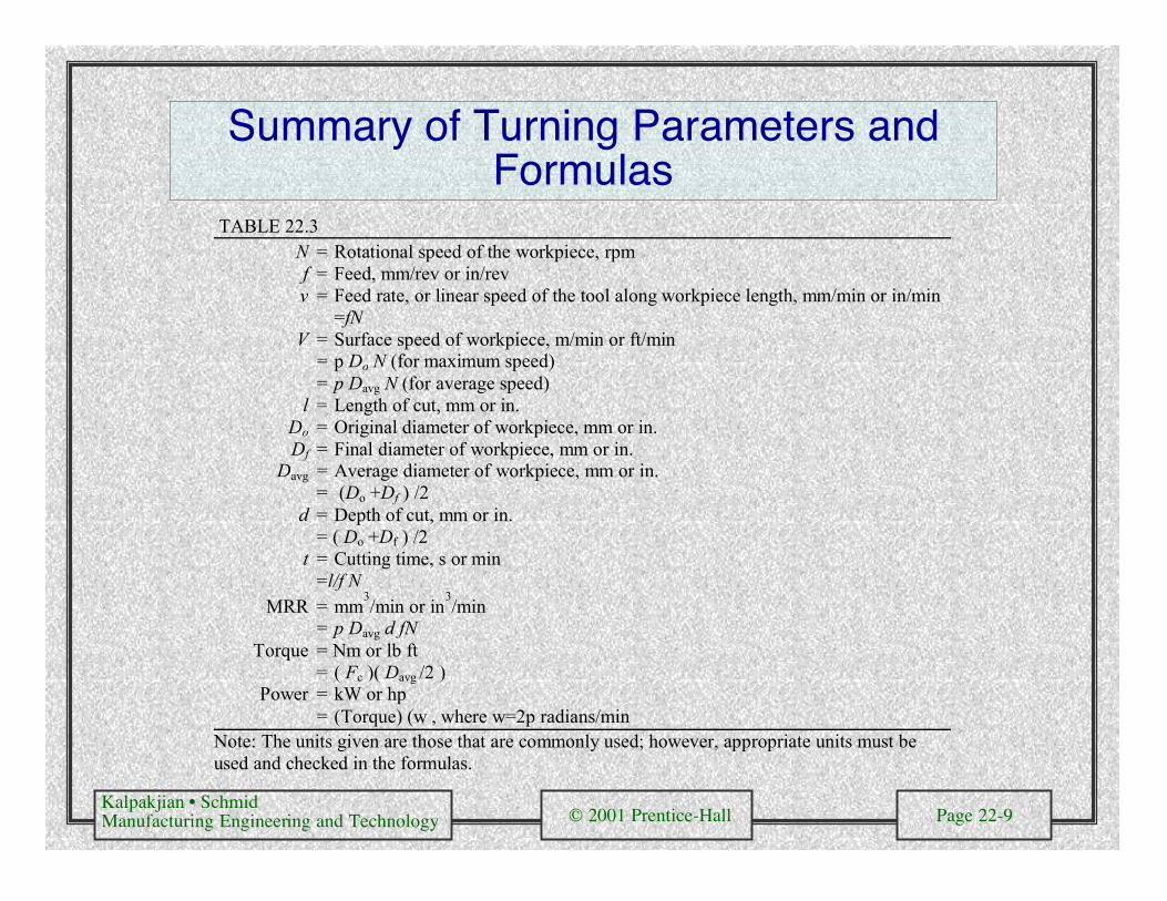
Summary of Turning Parameters andFormulas
TABLE 22.3N = Rotational speed of the workpiece, rpmf = Feed, mm/rev or in/revv = Feed rate, or linear speed of the tool along workpiece length, mm/min or in/min
=fNV = Surface speed of workpiece, m/min or ft/min
= p Do N (for maximum speed)= p Davg N (for average speed)
l = Length of cut, mm or in.Do = Original diameter of workpiece, mm or in.Df = Final diameter of workpiece, mm or in.
Davg = Average diameter of workpiece, mm or in.= (Do +Df ) /2
d = Depth of cut, mm or in.= ( Do +Df ) /2
t = Cutting time, s or min=l/f N
MRR = mm3/min or in
3/min
= p Davg d fNTorque = Nm or lb ft
= ( Fc )( Davg /2 )Power = kW or hp
= (Torque) (w , where w=2p radians/minNote: The units given are those that are commonly used; however, appropriate units must beused and checked in the formulas.

Kalpakjian • SchmidManufacturing Engineering and Technology © 2001 Prentice-Hall Page 22-10
Cutting Speeds for Various Tool Materials
Figure 22.5 The range of applicablecutting speeds and feeds for a variety oftool materials. Source: Valenite.

Kalpakjian • SchmidManufacturing Engineering and Technology © 2001 Prentice-Hall Page 22-11
General Recommendations for TurningOperations
TABLE 22.4General-purpose starting conditions Range for roughing and finishing
Workpiece material Cutting toolDepth of cut
mm (in.)
Feedmm/rev(in./rev)
Cutting speedm/min(ft/min)
Depth of cutmm(in.)
Feedmm/rev(in./rev)
Cutting speedm/min(ft/min)
Low-C and free-machining steels
Uncoatedcarbide
1.5-6.3(0.06-0.25)
0.35(0.014)
90(300)
0.5-7.6(0.02-0.30)
0.15-1.1(0.006-0.045)
60-135(200-450)
Ceramic-coatedcarbide
" " 245-275(800-900)
" " 120-425(400-1400)
Triple coatedcarbide
" " 185-200(600-650)
" " 90-245(300-800)
TiN-coatedcarbide
" " 105-150(350-500)
" " 60-230(200-750)
Al2O3 ceramic " 0.25(0.010)
395-440(1300-1450)
" " 365-550(1200-1800)
Cermet " 0.30(0.012)
215-290(700-950)
" " 105-455(350-1800)
Medium and high-Csteels
Uncoatedcarbide
1.2-4.0(0.05-0.20)
0.30(0.012)
75(250)
2.5-7.6(0.10-0.30)
0.15-0.75(0.006-0.03)
45-120(150-400)
Ceramic-coatedcarbide
" " 185-230(600-750)
" " 120-410(400-1350)
Triple coatedcarbide
" " 120-150(400-500)
" " 75-215(250-700)
TiN-coatedcarbide
" " 90-200(300-650)
" " 45-215(150-700)
Al2O3 ceramic " 0.25(0.010)
335(1100)
" " 245-455(800-1500)
Cermet " 0.25(0.010)
170-245(550-800)
" " 105-305(350-1000)
Kalpakjian • SchmidManufacturing Engineering and Technology © 2001 Prentice-Hall Page 22-12
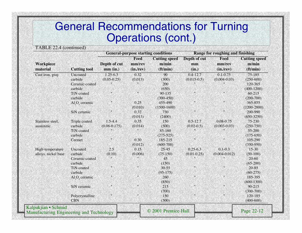
General Recommendations for TurningOperations (cont.)
TABLE 22.4 (continued)General-purpose starting conditions Range for roughing and finishing
Workpiecematerial Cutting tool
Depth of cutmm (in.)
Feedmm/rev(in./rev)
Cutting speedm/min(ft/min)
Depth of cutmm(in.)
Feedmm/rev(in./rev)
Cutting speedm/min
(ft/min)Cast iron, gray Uncoated
carbide1.25-6.3
(0.05-0.25)0.32
(0.013)90
(300)0.4-12.7
(0.015-0.5)0.1-0.75
(0.004-0.03)75-185
(250-600)Ceramic-coatedcarbide
" " 200(650)
" " 120-365(400-1200)
TiN-coatedcarbide
" " 90-135(300-450)
" " 60-215(200-700)
Al2O
3 ceramic " 0.25
(0.010)455-490
(1500-1600)" " 365-855
(1200-2800)SiN ceramic " 0.32
(0.013)730
(2400)" " 200-990
(650-3250)Stainless steel,austenitic
Triple coatedcarbide
1.5-4.4(0.06-0.175)
0.35(0.014)
150(500)
0.5-12.7(0.02-0.5)
0.08-0.75(0.003-0.03)
75-230(250-750)
TiN-coatedcarbide
" " 85-160(275-525)
" " 55-200(175-650)
Cermet " 0.30(0.012)
185-215(600-700)
" " 105-290(350-950)
High-temperaturealloys, nickel base
Uncoatedcarbide
2.5(0.10)
0.15(0.006)
25-45(75-150)
0.25-6.3(0.01-0.25)
0.1-0.3(0.004-0.012)
15-30(50-100)
Ceramic-coatedcarbide
" " 45(150)
" " 20-60(65-200)
TiN-coatedcarbide
" " 30-55(95-175)
" " 20-85(60-275)
Al2O
3 ceramic " " 260
(850)" " 185-395
(600-1300)SiN ceramic " " 215
(700)" " 90-215
(300-700)PolycrystallineCBN
" " 150(500)
" " 120-185(400-600)
Kalpakjian • SchmidManufacturing Engineering and Technology © 2001 Prentice-Hall Page 22-13
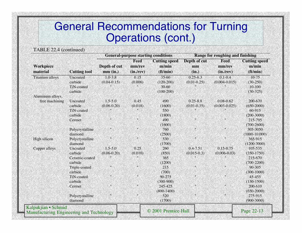
General Recommendations for TurningOperations (cont.)
TABLE 22.4 (continued)General-purpose starting conditions Range for roughing and finishing
Workpiecematerial Cutting tool
Depth of cutmm (in.)
Feedmm/rev(in./rev)
Cutting speedm/min
(ft/min)
Depth of cutmm(in.)
Feedmm/rev(in./rev)
Cutting speedm/min
(ft/min)Titanium alloys Uncoated
carbide1.0-3.8
(0.04-0.15)0.15
(0.006)35-60
(120-200)0.25-6.3
(0.01-0.25)0.1-0.4
(0.004-0.015)10-75
(30-250)TiN-coatedcarbide
" " 30-60(100-200)
" " 10-100(30-325)
Aluminum alloys,free machining Uncoated
carbide1.5-5.0
(0.06-0.20)0.45
(0.018)490
(1600)0.25-8.8
(0.01-0.35)0.08-0.62
(0.003-0.025)200-670
(650-2000)TiN-coatedcarbide
" " 550(1800)
" " 60-915(200-3000)
Cermet " " 490(1600)
" " 215-795(700-2600)
Polycrystallinediamond
" " 760(2500)
" " 305-3050(1000-10,000)
High silicon Polycrystallinediamond
" " 530(1700)
" " 365-915(1200-3000)
Copper alloys Uncoatedcarbide
1.5-5.0(0.06-0.20)
0.25(0.010)
260(850)
0.4-7.51(0.015-0.3)
0.15-0.75(0.006-0.03)
105-535(350-1750)
Ceramic-coatedcarbide
" " 365(1200)
" " 215-670(700-2200)
Triple-coatedcarbide
" " 215(700)
" " 90-305(300-1000)
TiN-coatedcarbide
" " 90-275(300-900)
" " 45-455(150-1500)
Cermet " " 245-425(800-1400)
" " 200-610(650-2000)
Polycrystallinediamond
" " 520(1700)
" " 275-915(900-3000)
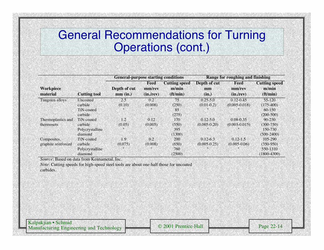
Kalpakjian • SchmidManufacturing Engineering and Technology © 2001 Prentice-Hall Page 22-14
General Recommendations for TurningOperations (cont.)
General-purpose starting conditions Range for roughing and finishing
Workpiecematerial Cutting tool
Depth of cutmm (in.)
Feedmm/rev(in./rev)
Cutting speedm/min(ft/min)
Depth of cutmm(in.)
Feedmm/rev(in./rev)
Cutting speedm/min
(ft/min)Tungsten alloys Uncoated
carbide2.5
(0.10)0.2
(0.008)75
(250)0.25-5.0
(0.01-0.2)0.12-0.45
(0.005-0.018)55-120
(175-400)TiN-coatedcarbide
" " 85(275)
" " 60-150(200-500)
Thermoplastics andthermosets
TiN-coatedcarbide
1.2(0.05)
0.12(0.005)
170(550)
0.12-5.0(0.005-0.20)
0.08-0.35(0.003-0.015)
90-230(300-750)
Polycrystallinediamond
" " 395(1300)
" " 150-730(500-2400)
Composites,graphite reinforced
TiN-coatedcarbide
1.9(0.075)
0.2(0.008)
200(650)
0.12-6.3(0.005-0.25)
0.12-1.5(0.005-0.06)
105-290(350-950)
Polycrystallinediamond
" " 760(2500)
" " 550-1310(1800-4300)
Source: Based on data from Kennametal, Inc.Note: Cutting speeds for high-speed steel tools are about one-half those for uncoatedcarbides.
Kalpakjian • SchmidManufacturing Engineering and Technology © 2001 Prentice-Hall Page 22-15
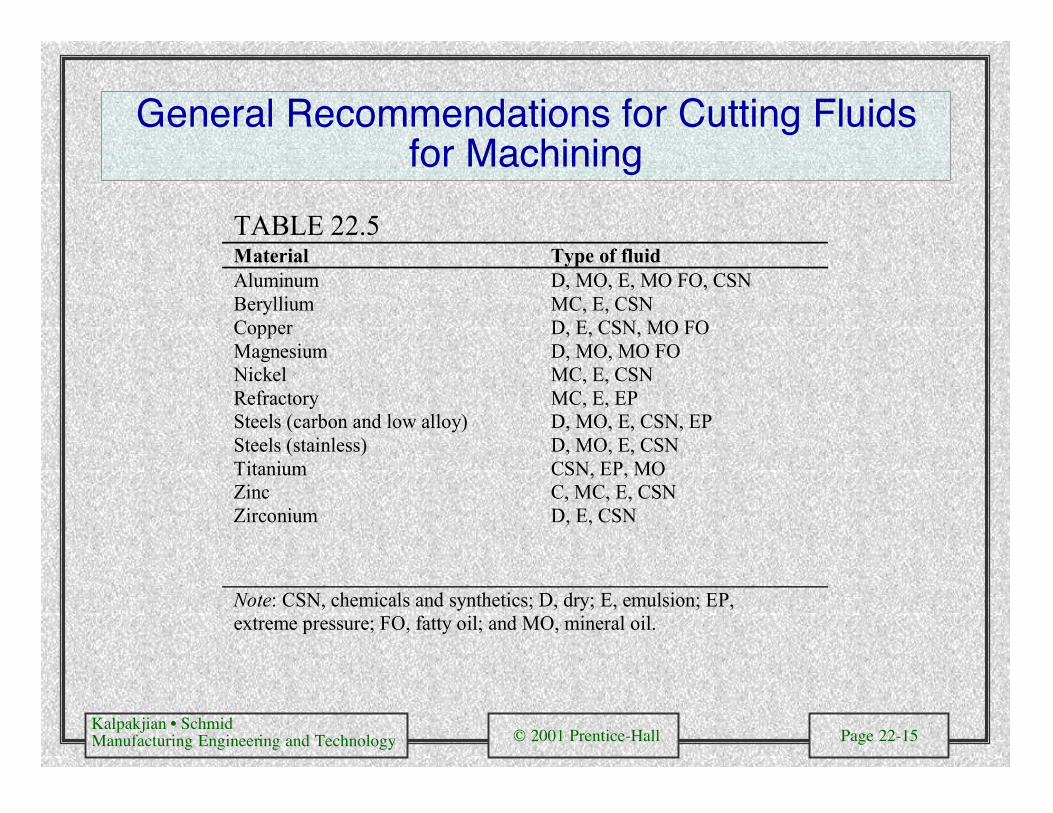
General Recommendations for Cutting Fluidsfor Machining
TABLE 22.5Material Type of fluidAluminumBerylliumCopperMagnesiumNickelRefractorySteels (carbon and low alloy)Steels (stainless)TitaniumZincZirconium
D, MO, E, MO FO, CSNMC, E, CSND, E, CSN, MO FOD, MO, MO FOMC, E, CSNMC, E, EPD, MO, E, CSN, EPD, MO, E, CSNCSN, EP, MOC, MC, E, CSND, E, CSN
Note: CSN, chemicals and synthetics; D, dry; E, emulsion; EP,extreme pressure; FO, fatty oil; and MO, mineral oil.
Kalpakjian • SchmidManufacturing Engineering and Technology © 2001 Prentice-Hall Page 22-16
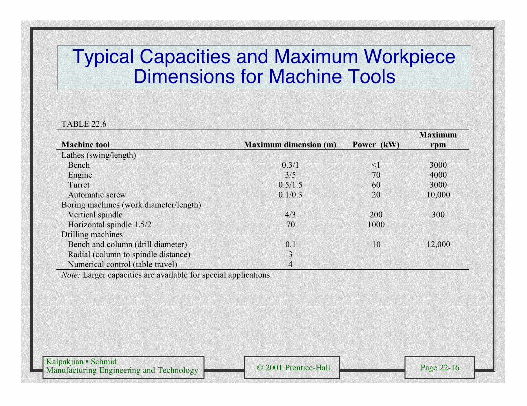
Typical Capacities and Maximum WorkpieceDimensions for Machine Tools
TABLE 22.6
Machine tool Maximum dimension (m) Power (kW)Maximum
rpmLathes (swing/length) Bench 0.3/1 <1 3000 Engine 3/5 70 4000 Turret 0.5/1.5 60 3000 Automatic screw 0.1/0.3 20 10,000Boring machines (work diameter/length) Vertical spindle 4/3 200 300 Horizontal spindle 1.5/2 70 1000Drilling machines Bench and column (drill diameter) 0.1 10 12,000 Radial (column to spindle distance) 3 — — Numerical control (table travel) 4 — —Note: Larger capacities are available for special applications.
Kalpakjian • SchmidManufacturing Engineering and Technology © 2001 Prentice-Hall Page 22-17
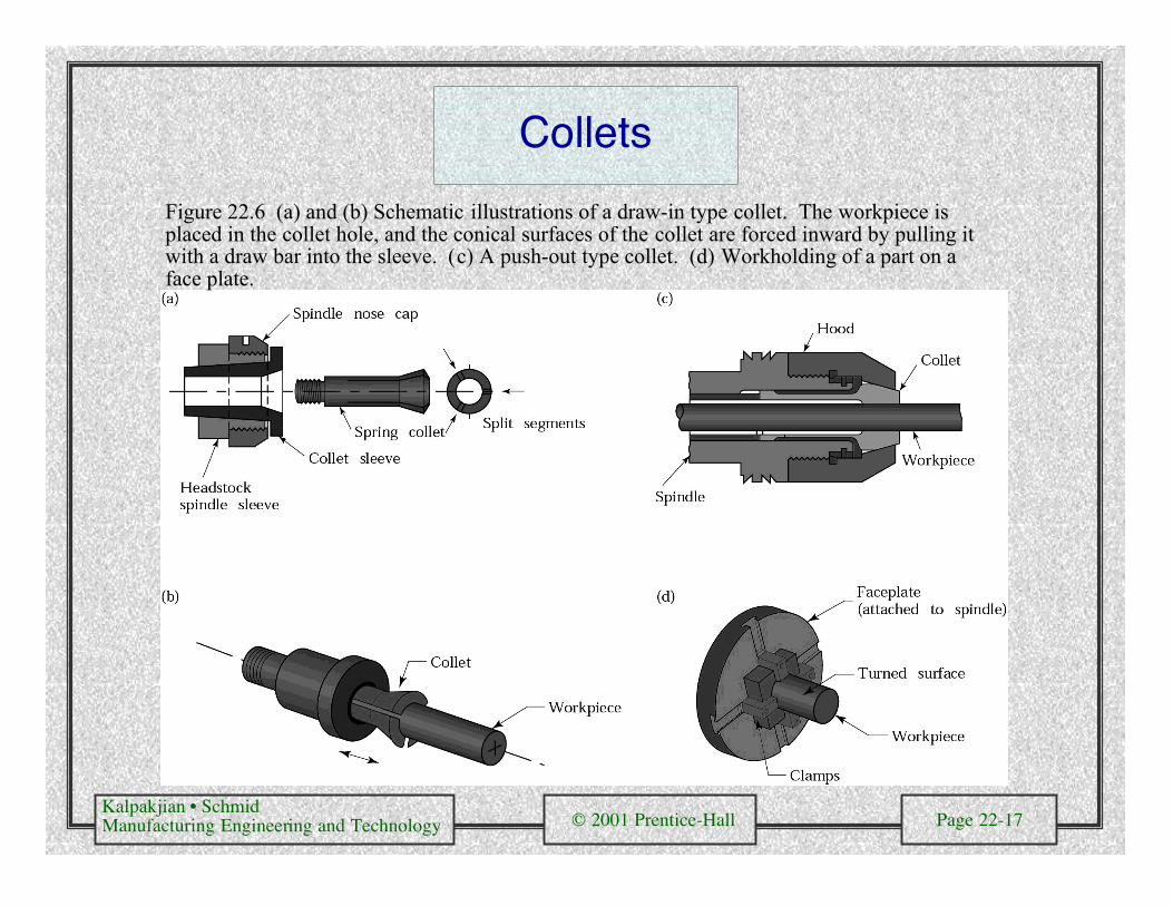
Collets
Figure 22.6 (a) and (b) Schematic illustrations of a draw-in type collet. The workpiece isplaced in the collet hole, and the conical surfaces of the collet are forced inward by pulling itwith a draw bar into the sleeve. (c) A push-out type collet. (d) Workholding of a part on aface plate.
Kalpakjian • SchmidManufacturing Engineering and Technology © 2001 Prentice-Hall Page 22-18
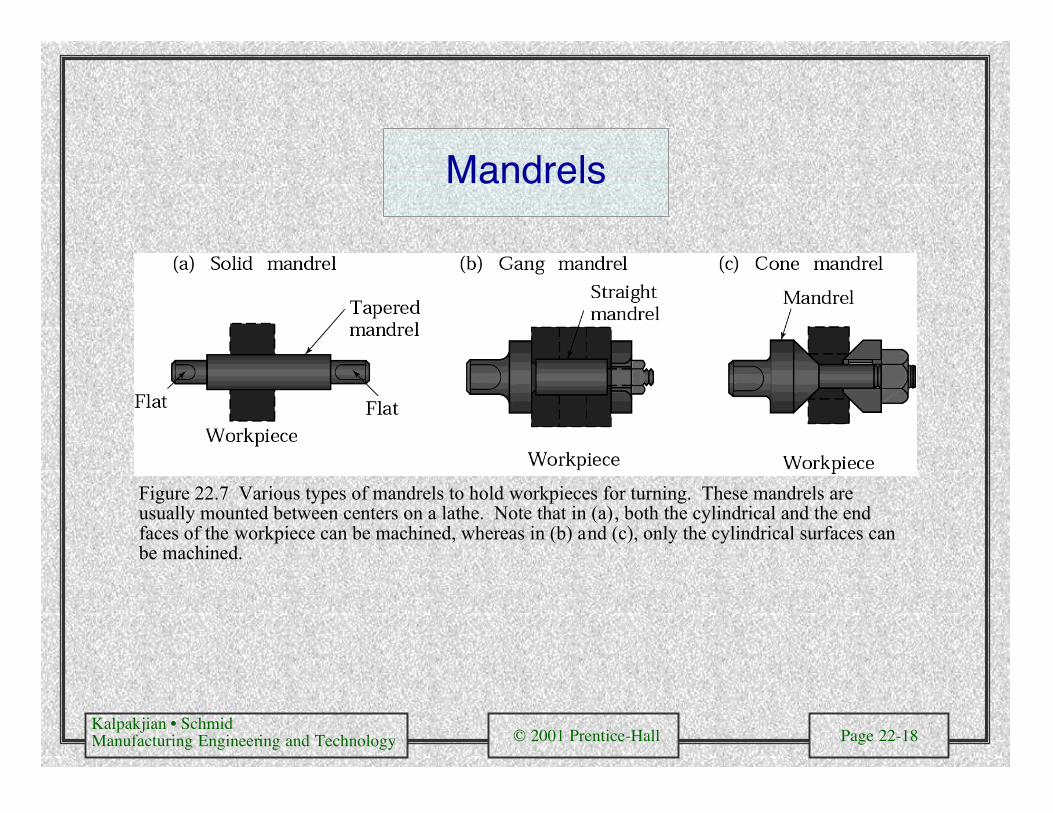
Mandrels
Figure 22.7 Various types of mandrels to hold workpieces for turning. These mandrels areusually mounted between centers on a lathe. Note that in (a), both the cylindrical and the endfaces of the workpiece can be machined, whereas in (b) and (c), only the cylindrical surfaces canbe machined.

Kalpakjian • SchmidManufacturing Engineering and Technology © 2001 Prentice-Hall Page 22-19
Swiss-Type Automatic Screw Machine
Figure 22.8 Schematic illustration of aSwiss-type automatic screw machine.Source: George Gorton Machine Company.

Kalpakjian • SchmidManufacturing Engineering and Technology © 2001 Prentice-Hall Page 22-20
Turret Lathe
Figure 22.9 Schematicillustration of the componentsof a turret lathe. Note the twoturrets: square and hexagonal(main). Source: AmericanMachinist and AutomatedManufacturing.
Kalpakjian • SchmidManufacturing Engineering and Technology © 2001 Prentice-Hall Page 22-21
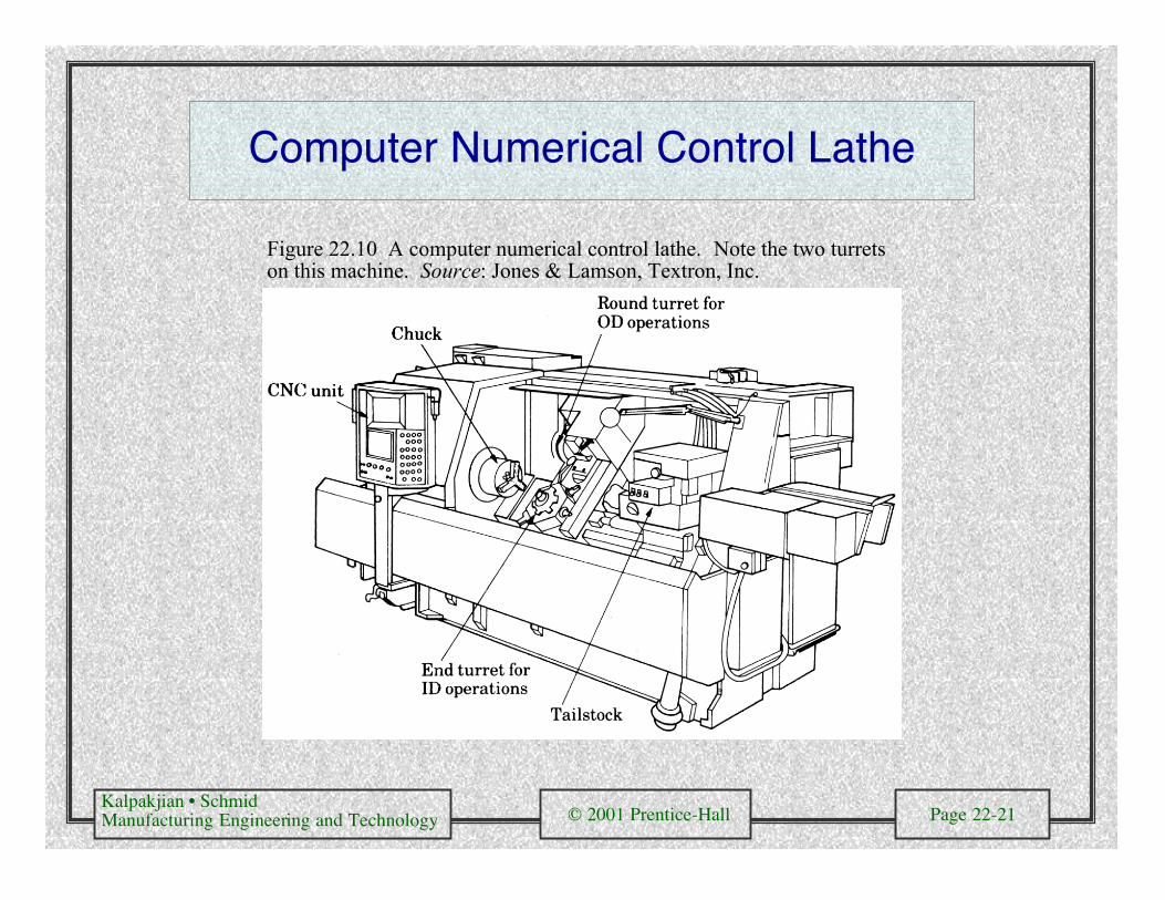
Computer Numerical Control Lathe
Figure 22.10 A computer numerical control lathe. Note the two turretson this machine. Source: Jones & Lamson, Textron, Inc.

Kalpakjian • SchmidManufacturing Engineering and Technology © 2001 Prentice-Hall Page 22-22
Examples of Turrets
(a) (b)
Figure 22.11 (a) A turret with six different tools for inside-diameter andoutside-diameter cutting and threading operations. (b) A turret with eightdifferent cutting tools. Source: Monarch Machine Tool Company.

Kalpakjian • SchmidManufacturing Engineering and Technology © 2001 Prentice-Hall Page 22-23
Examples of Parts Made on CNC TurningMachine Tools
Figure 22.12
Kalpakjian • SchmidManufacturing Engineering and Technology © 2001 Prentice-Hall Page 22-24
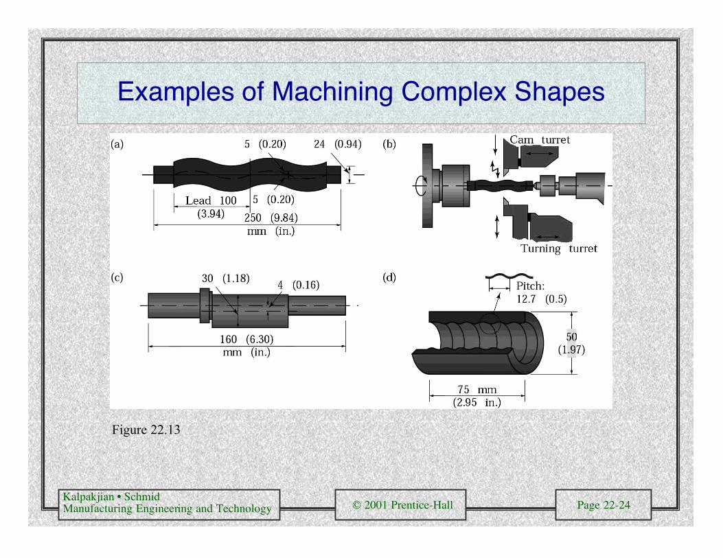
Examples of Machining Complex Shapes
Figure 22.13
Kalpakjian • SchmidManufacturing Engineering and Technology © 2001 Prentice-Hall Page 22-25
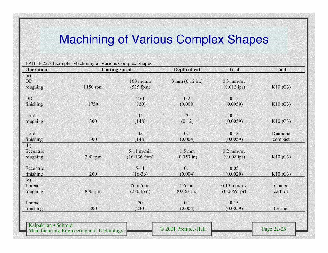
Machining of Various Complex Shapes
TABLE 22.7 Example: Machining of Various Complex ShapesOperation Cutting speed Depth of cut Feed Tool(a)ODroughing 1150 rpm
160 m/min(525 fpm)
3 mm (0.12 in.) 0.3 mm/rev(0.012 ipr) K10 (C3)
ODfinishing 1750
250(820)
0.2(0.008)
0.15(0.0059) K10 (C3)
Leadroughing 300
45(148)
3(0.12)
0.15(0.0059) K10 (C3)
Leadfinishing 300
45(148)
0.1(0.004)
0.15(0.0059)
Diamondcompact
(b)Eccentricroughing 200 rpm
5-11 m/min(16-136 fpm)
1.5 mm(0.059 in)
0.2 mm/rev(0.008 ipr) K10 (C3)
Eccentricfinishing 200
5-11(16-36)
0.1(0.004)
0.05(0.0020) K10 (C3)
(c)Threadroughing 800 rpm
70 m/min(230 fpm)
1.6 mm(0.063 in.)
0.15 mm/rev(0.0059 ipr)
Coatedcarbide
Threadfinishing 800
70(230)
0.1(0.004)
0.15(0.0059) Cermet
Kalpakjian • SchmidManufacturing Engineering and Technology © 2001 Prentice-Hall Page 22-26
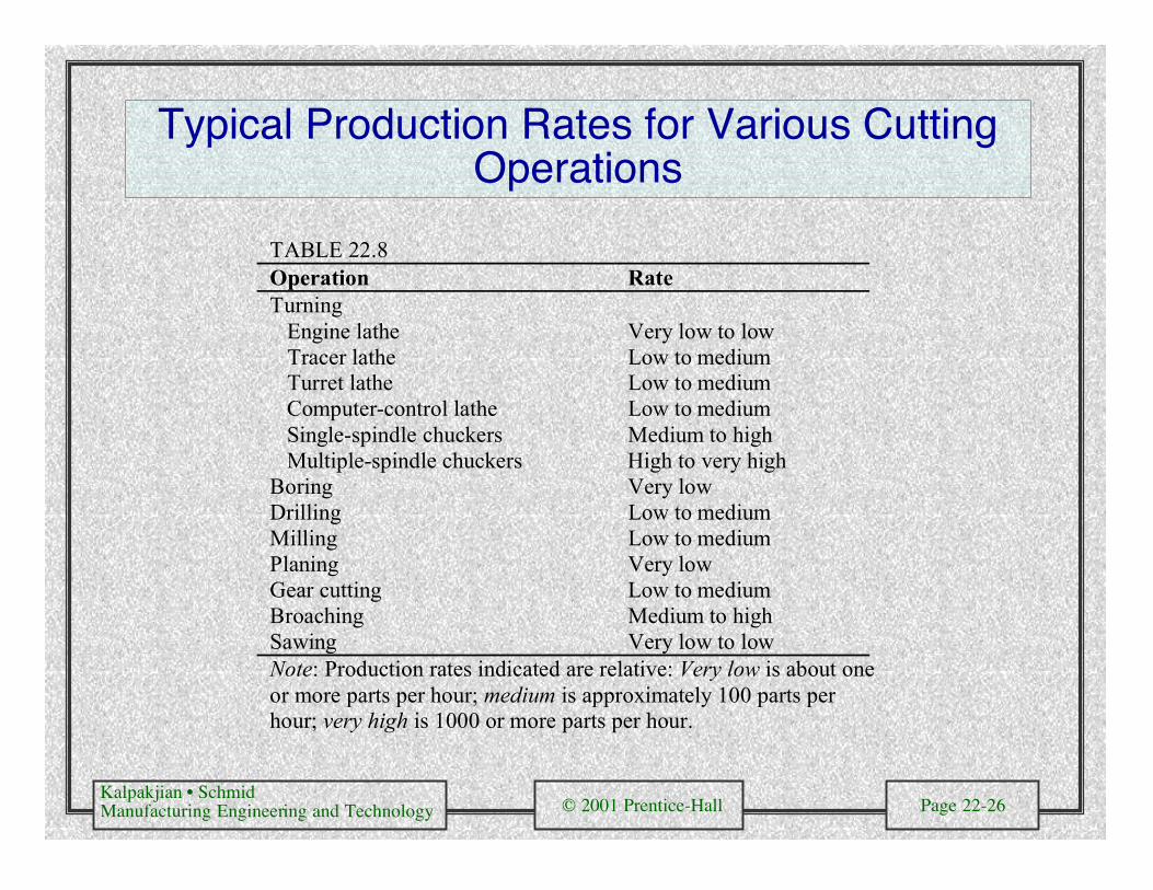
Typical Production Rates for Various CuttingOperations
TABLE 22.8Operation RateTurning Engine lathe Very low to low Tracer lathe Low to medium Turret lathe Low to medium Computer-control lathe Low to medium Single-spindle chuckers Medium to high Multiple-spindle chuckers High to very highBoring Very lowDrilling Low to mediumMilling Low to mediumPlaning Very lowGear cutting Low to mediumBroaching Medium to highSawing Very low to lowNote: Production rates indicated are relative: Very low is about oneor more parts per hour; medium is approximately 100 parts perhour; very high is 1000 or more parts per hour.
Kalpakjian • SchmidManufacturing Engineering and Technology © 2001 Prentice-Hall Page 22-27
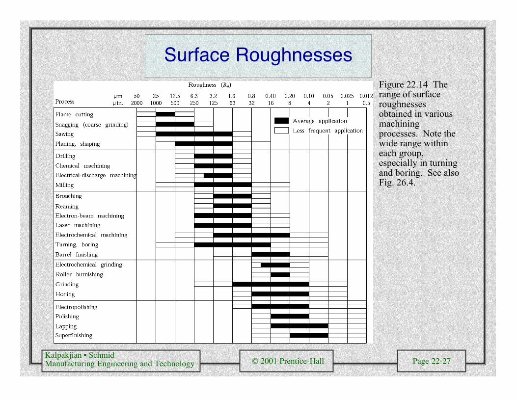
Surface RoughnessesFigure 22.14 Therange of surfaceroughnessesobtained in variousmachiningprocesses. Note thewide range withineach group,especially in turningand boring. See alsoFig. 26.4.
Kalpakjian • SchmidManufacturing Engineering and Technology © 2001 Prentice-Hall Page 22-28
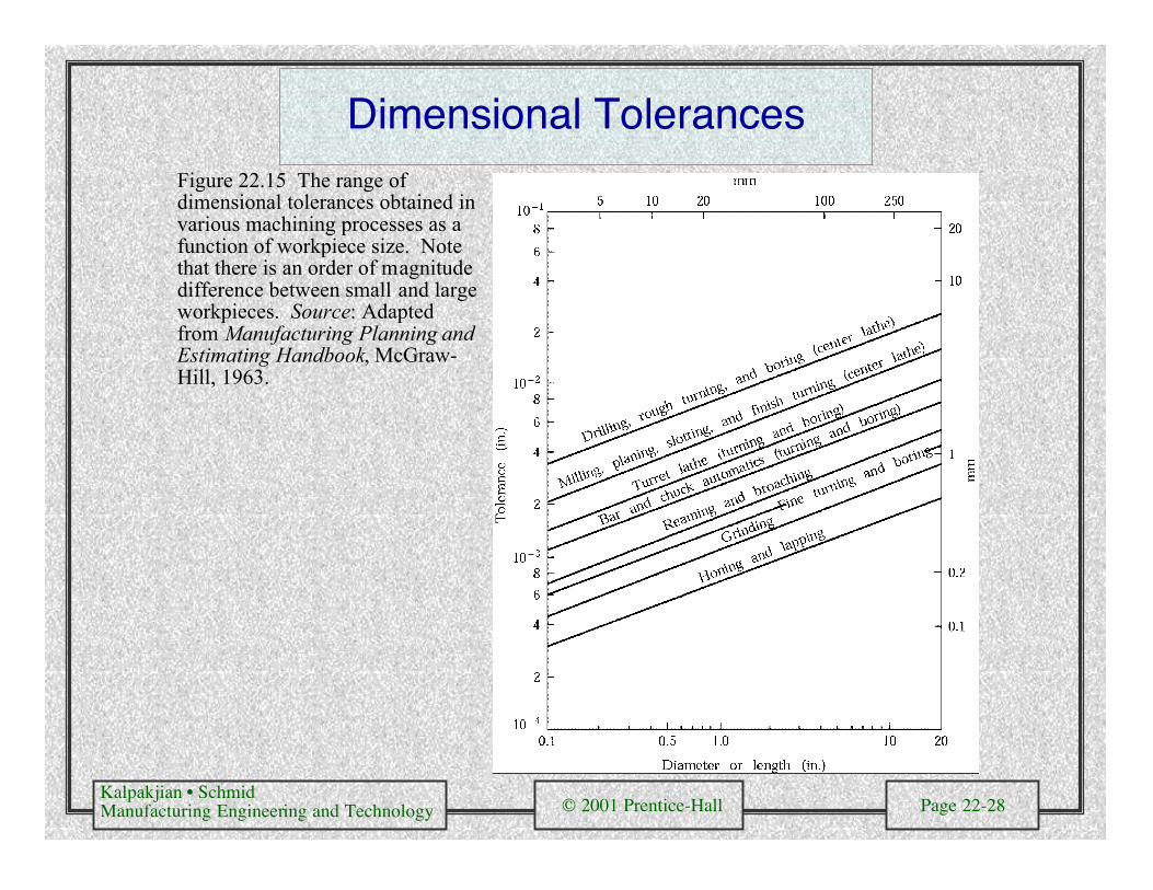
Dimensional TolerancesFigure 22.15 The range ofdimensional tolerances obtained invarious machining processes as afunction of workpiece size. Notethat there is an order of magnitudedifference between small and largeworkpieces. Source: Adaptedfrom Manufacturing Planning andEstimating Handbook, McGraw-Hill, 1963.
Kalpakjian • SchmidManufacturing Engineering and Technology © 2001 Prentice-Hall Page 22-29
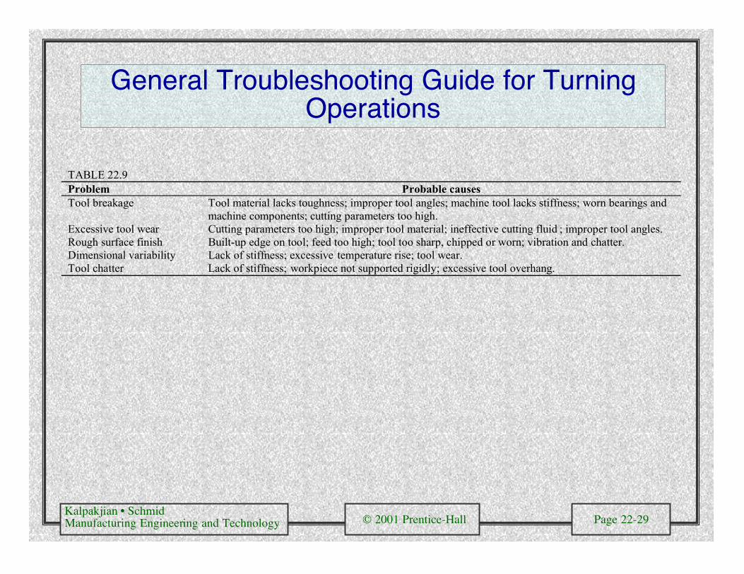
General Troubleshooting Guide for TurningOperations
TABLE 22.9Problem Probable causesTool breakage Tool material lacks toughness; improper tool angles; machine tool lacks stiffness; worn bearings and
machine components; cutting parameters too high.Excessive tool wear Cutting parameters too high; improper tool material; ineffective cutting fluid ; improper tool angles.Rough surface finish Built-up edge on tool; feed too high; tool too sharp, chipped or worn; vibration and chatter.Dimensional variability Lack of stiffness; excessive temperature rise; tool wear.Tool chatter Lack of stiffness; workpiece not supported rigidly; excessive tool overhang.
Kalpakjian • SchmidManufacturing Engineering and Technology © 2001 Prentice-Hall Page 22-30
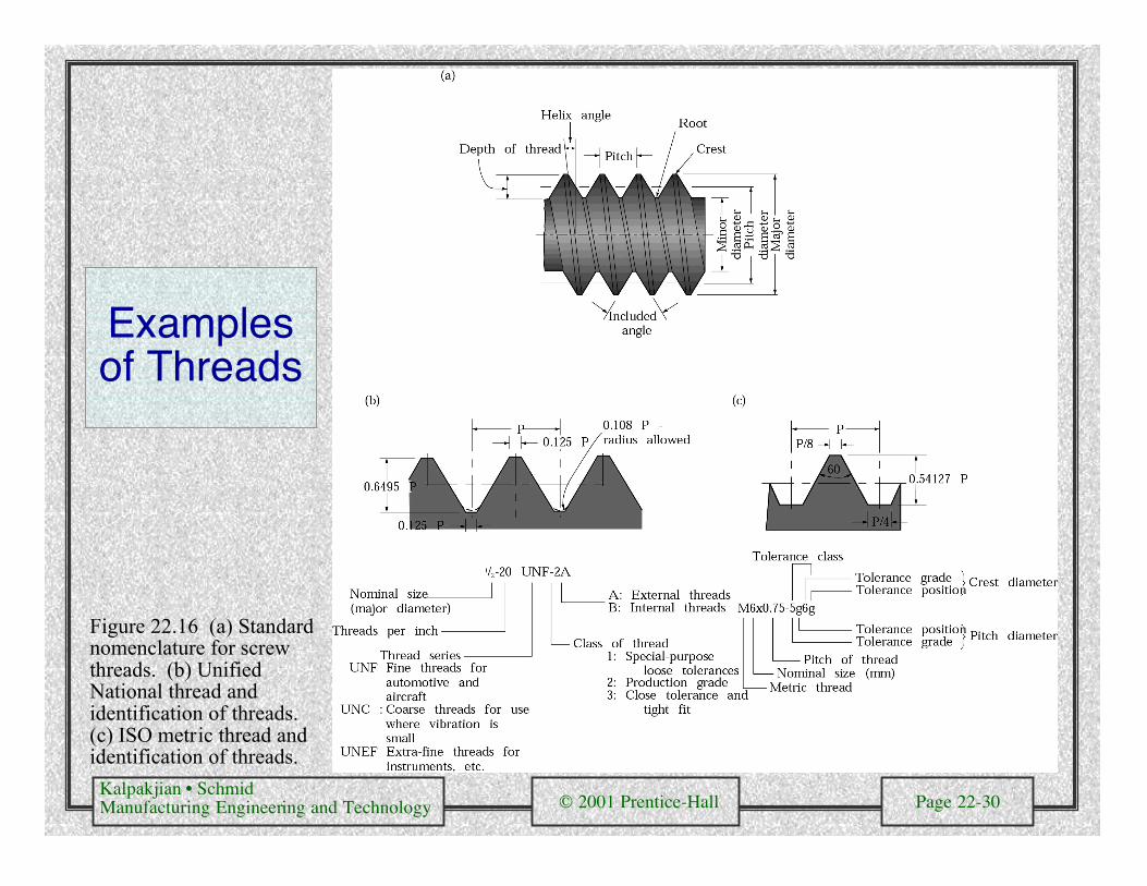
Examplesof Threads
Figure 22.16 (a) Standardnomenclature for screwthreads. (b) UnifiedNational thread andidentification of threads.(c) ISO metric thread andidentification of threads.

Kalpakjian • SchmidManufacturing Engineering and Technology © 2001 Prentice-Hall Page 22-31
Types of Screw Threads
Figure 22.17 Various types of screw threads.

Kalpakjian • SchmidManufacturing Engineering and Technology © 2001 Prentice-Hall Page 22-32
Cutting Screw Threads
Figure 22.18 (a) Cutting screw threads on a lathe with a single-point cutting tool. (b) Cutting screw threadswith a single-point tool in several passes, normally utilized for large threads. The small arrows in the figuresshow the direction of feed, and the broken lines show the position of the cutting tool as time progresses. Notethat in radial cutting, the tool is fed directly into the workpiece. In flank cutting, the tool is fed into the piecealong the right face of the thread. In incremental cutting, the tool is first fed directly into the piece at the centerof the thread, then at its sides, and finally into the root. (c) A typical carbide insert and toolholder for cuttingscrew threads. (d) Cutting internal screw threads with a carbide insert. (See also Figs. 21.2 and 21.3.)

Kalpakjian • SchmidManufacturing Engineering and Technology © 2001 Prentice-Hall Page 22-33
Threading Die
Figure 22.19 (a) Straight chasers for cutting threads on a lathe. (b) Circular chasers. (c) Asolid threading die.

Kalpakjian • SchmidManufacturing Engineering and Technology © 2001 Prentice-Hall Page 22-34
Boring
Figure 22.20 (a) Schematic illustration of a steel boring bar with a carbide insert. Note the passagewayin the bar for cutting fluid application. (b) Schematic illustration of a boring bar with tungsten-alloy“inertia disks” sealed in the bar to counteract vibration and chatter during boring. This system iseffective for boring bar length-to-diameter ratios of up to 6. (c) Schematic illustration of thecomponents of a vertical boring mill. Source: Kennametal Inc.
Kalpakjian • SchmidManufacturing Engineering and Technology © 2001 Prentice-Hall Page 22-35
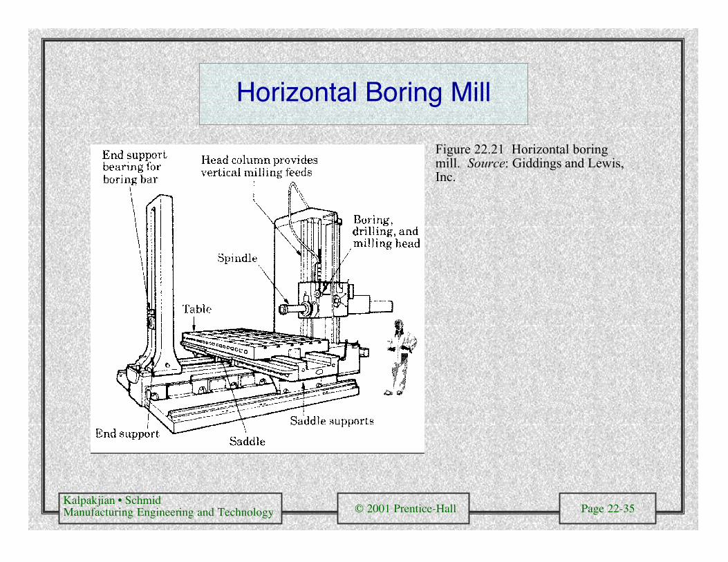
Horizontal Boring Mill
Figure 22.21 Horizontal boringmill. Source: Giddings and Lewis,Inc.
Kalpakjian • SchmidManufacturing Engineering and Technology © 2001 Prentice-Hall Page 22-36
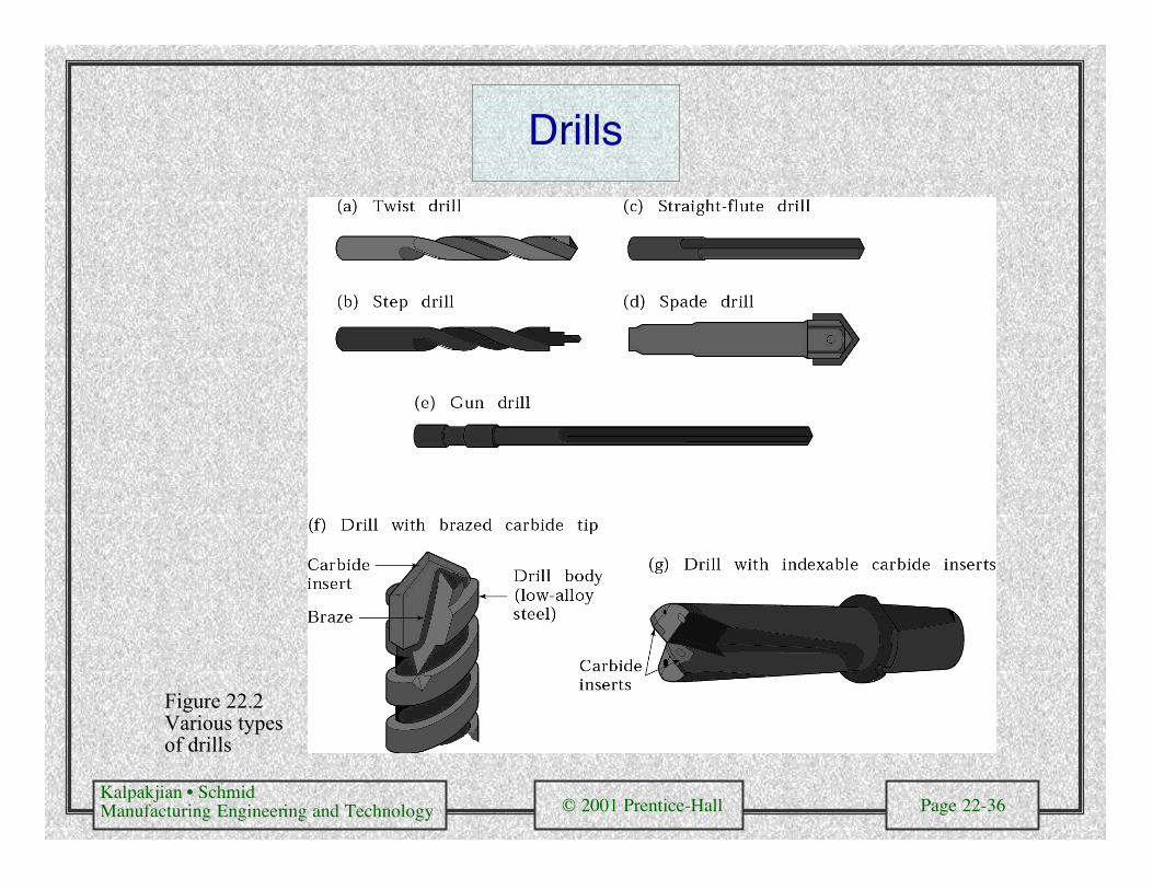
Drills
Figure 22.2Various typesof drills

Kalpakjian • SchmidManufacturing Engineering and Technology © 2001 Prentice-Hall Page 22-37
Drill Point Geometries
Figure 22.23 (a) Standard chisel-point drill indicating various features. The function of the pair of margins is toprovide a bearing surface for the drill against walls of the hole as it penetrates into the workpiece; drills withfour margins (double-margin) are available for improved drill guidance and accuracy. Drills with chip-breakerfeatures are also available. (b) Crankshaft-point drill. (c) Various drill points and their manufacturers: 1. Four-facet split point, by Komet of America. 2. SE point, by Hertel. 3. New point, by Mitsubishi Materials. 4. Hosoipoint, by OSG Tap and Die. 5. Helical point.
Kalpakjian • SchmidManufacturing Engineering and Technology © 2001 Prentice-Hall Page 22-38
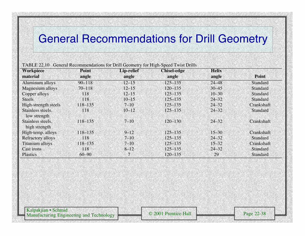
General Recommendations for Drill Geometry
TABLE 22.10 General Recommendations for Drill Geometry for High-Speed Twist DrillsWorkpiecematerial
Pointangle
Lip-reliefangle
Chisel-edgeangle
Helixangle Point
Aluminum alloys 90–118 12–15 125–135 24–48 StandardMagnesium alloys 70–118 12–15 120–135 30–45 StandardCopper alloys 118 12–15 125–135 10–30 StandardSteels 118 10–15 125–135 24–32 StandardHigh-strength steels 118–135 7–10 125–135 24–32 CrankshaftStainless steels, low strength
118 10–12 125–135 24–32 Standard
Stainless steels, high strength
118–135 7–10 120–130 24–32 Crankshaft
High-temp. alloys 118–135 9–12 125–135 15–30 CrankshaftRefractory alloys 118 7–10 125–135 24–32 StandardTitanium alloys 118–135 7–10 125–135 15–32 CrankshaftCast irons 118 8–12 125–135 24–32 StandardPlastics 60–90 7 120–135 29 Standard

Kalpakjian • SchmidManufacturing Engineering and Technology © 2001 Prentice-Hall Page 22-39
Drilling and Reaming Operations
Figure 22.24 Various typesof drilling and reamingoperations.

Kalpakjian • SchmidManufacturing Engineering and Technology © 2001 Prentice-Hall Page 22-40
Gun Drilling
Figure 22.25 (a) A gun drill showingvarious features. (b) Method of gundrilling. Source: Eldorado Tool andManufacturing Corporation.

Kalpakjian • SchmidManufacturing Engineering and Technology © 2001 Prentice-Hall Page 22-41
Trepanning
Figure 22.26 (a) Trepanning tool. (b) Trepanning with a drill-mounted single cutter.

Kalpakjian • SchmidManufacturing Engineering and Technology © 2001 Prentice-Hall Page 22-42
Capabilities of Drilling and BoringOperations
TABLE 22.11Diameter Hole depth/diameter
Tool typerange(mm) Typical Maximum
Twist 0.5–150 8 50Spade 25–150 30 100Gun 2–50 100 300Trepanning 40–250 10 100Boring 3–1200 5 8

Kalpakjian • SchmidManufacturing Engineering and Technology © 2001 Prentice-Hall Page 22-43
General Recommendations for Speeds andFeeds in Drilling
TABLE 22.12
Surface speedFeed, mm/rev (in/rev)
Drill Diameter RPMWorkpiecematerial m/min ft/min 1.5 mm (0.060 in.) 12.5 mm (0.5 in.) 1.5 mm 12.5 mmAluminum alloys 30–120 100–400 0.025 (0.001) 0.30 (0.012) 6400–25,000 800–3000Magnesium alloys 45–120 150–400 0.025 (0.001) 0.30 (0.012) 9600–25,000 1100–3000Copper alloys 15–60 50–200 0.025 (0.001) 0.25 (0.010) 3200–12,000 400–1500Steels 20–30 60–100 0.025 (0.001) 0.30 (0.012) 4300–6400 500–800Stainless steels 10–20 40–60 0.025 (0.001) 0.18 (0.007) 2100–4300 250–500Titanium alloys 6–20 20–60 0.010 (0.0004) 0.15 (0.006) 1300–4300 150–500Cast irons 20–60 60–200 0.025 (0.001) 0.30 (0.012) 4300–12,000 500–1500Thermoplastics 30–60 100–200 0.025 (0.001) 0.13 (0.005) 6400–12,000 800–1500Thermosets 20–60 60–200 0.025 (0.001) 0.10 (0.004) 4300–12,000 500–1500
Note: As hole depth increases, speeds and feeds should be reduced. Selection of speedsand feeds also depends on the specific surface finish required.

Kalpakjian • SchmidManufacturing Engineering and Technology © 2001 Prentice-Hall Page 22-44
General Troubleshooting and Drill Life
TABLE 22.12 General Troubleshooting Guide for Drilling OperationsProblem Probable causesDrill breakage Dull drill; drill seizing in hole because of chips clogging flutes; feed too high; lip
relief angle too small.Excessive drill wear Cutting speed too high; ineffective cutting fluid; rake angle too high; drill burned
and strength lost when sharpened.Tapered hole Drill misaligned or bent; lips not equal; web not central.Oversize hole Same as above; machine spindle loose; chisel edge not central; side pressure on
workpiece.Poor hole surface finish Dull drill; ineffective cutting fluid; welding of workpiece material on drill margin;
improperly ground drill; improper alignment.
Figure 22.27 The determination of drilllife by monitoring the rise in force ortorque as a function of the number of holesdrilled. This test is also used fordetermining tap life.

Kalpakjian • SchmidManufacturing Engineering and Technology © 2001 Prentice-Hall Page 22-45
Drilling Machines
Figure 22.28 Schematic illustration of components of (a) a vertical drill press and (b) a radial drillingmachine.
(a) (b)

Kalpakjian • SchmidManufacturing Engineering and Technology © 2001 Prentice-Hall Page 22-46
CNC Drilling Machine
Figure 22.29 A three-axiscomputer numerical controldrilling machine. The turretholds as much as eight differenttools, such as drills, taps, andreamers.

Kalpakjian • SchmidManufacturing Engineering and Technology © 2001 Prentice-Hall Page 22-47
Reamers
Figure 22.30 (a)Terminology for a helicalreamer. (b) Inserted-bladeadjustable reamer.

Kalpakjian • SchmidManufacturing Engineering and Technology © 2001 Prentice-Hall Page 22-48
Tapping and Taps
Figure 22.31 (a) Terminology for a tap. (b) Tapping of steel nuts in production.