Embed Size (px)
Citation preview
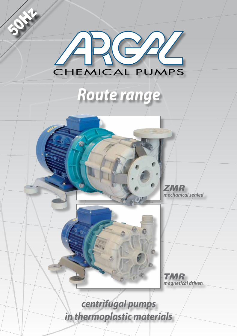
centrifugal pumpsin thermoplastic materials
Route range
ZMRmechanical sealed
TMRmagnetical driven
50Hz
2 Route TMR - ZMR
In this catalog Argal proposes the range of ROUTE pumps, inclusive of magnetical driven serie named TMR embedding innovative patented technology, and traditional mechanical sealed serie named ZMR.
ARGAL with these series, offers more than competitors a complete solutions to pump almost all the chemical liquids: aggressive, clean or with solid in suspension included lightly abrasives.
The advantages of these series are • simple and innovative constructions • suitability to transfer chemicals in industrial applications • minimised maintenance • no need of specialized after sales service centers • affordable purchase price and low operative cost.
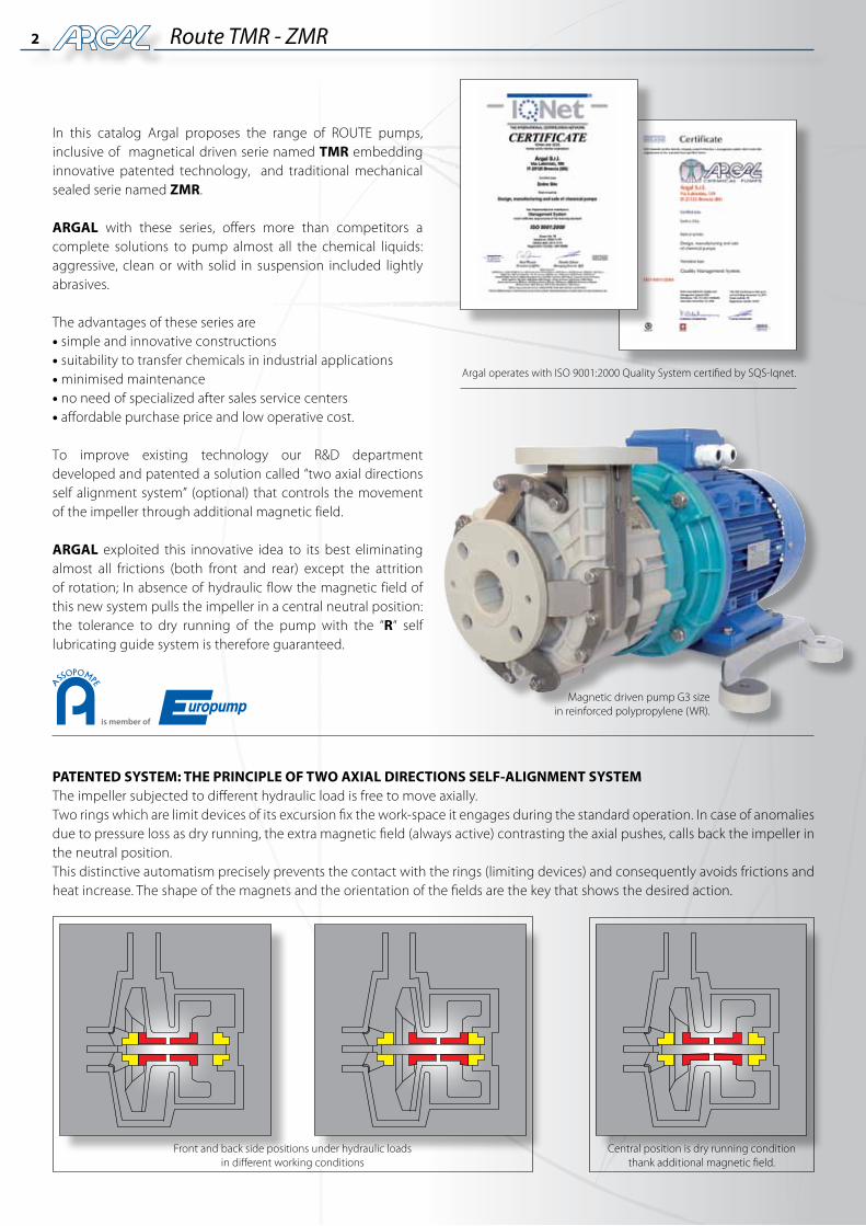
To improve existing technology our R&D department developed and patented a solution called “two axial directions self alignment system” (optional) that controls the movement of the impeller through additional magnetic field.
ARGAL exploited this innovative idea to its best eliminating almost all frictions (both front and rear) except the attrition of rotation; In absence of hydraulic flow the magnetic field of this new system pulls the impeller in a central neutral position: the tolerance to dry running of the pump with the “R“ self lubricating guide system is therefore guaranteed.
Front and back side positions under hydraulic loads in different working conditions
Central position is dry running conditionthank additional magnetic field.
Argal operates with ISO 9001:2000 Quality System certified by SQS-Iqnet.
PATENTED SYSTEM: THE PRINCIPLE OF TWO AXIAL DIRECTIONS SELF-ALIGNMENT SYSTEM The impeller subjected to different hydraulic load is free to move axially. Two rings which are limit devices of its excursion fix the work-space it engages during the standard operation. In case of anomalies due to pressure loss as dry running, the extra magnetic field (always active) contrasting the axial pushes, calls back the impeller in the neutral position. This distinctive automatism precisely prevents the contact with the rings (limiting devices) and consequently avoids frictions and heat increase. The shape of the magnets and the orientation of the fields are the key that shows the desired action.
is member of
Magnetic driven pump G3 sizein reinforced polypropylene (WR).
3Route TMR - ZMR
Labels in this catalog
GFR/PP Glass fibre reinforced Polypropylene (30%) EPDM Etylene-Propylene rubber
CFF/E-CTFE Etylene-Chloro Trifluoro Ethylene carbon fibre filled (20%) BSP - m BSP parallel threaded male connect. (according to ISO 7/1)
CARB. H.D. Carbon hight density NPT - m Threaded male NPT connections
SiC Silicon Carbide ND Nominal diameter
CER Alumina ceramic at 99,7% ISO Ref. Flange ISO 2084 - NP10
GFR/PTFE Glass fibre reinforced PTFE ANSI Ref. Flange ANSI B 16.5 – Flat Face
FKM Fluorine elastomer IEC According to E.C. motors
FFKM Perfluorelastomer NEMA Accordind to U.S. motors
50
45
40
35
30
25
20
15
10
5
0
Hea
d (m
)
m3/hCapacity
L/1’
0 2 4 6 8 10 12 14 16 18 20 22 24 26 28 30 32 34 36 38 40 42 44 46 48 50
0 50 100 150 200 250 300 350 400 450 500 550 600 650 700 750 800
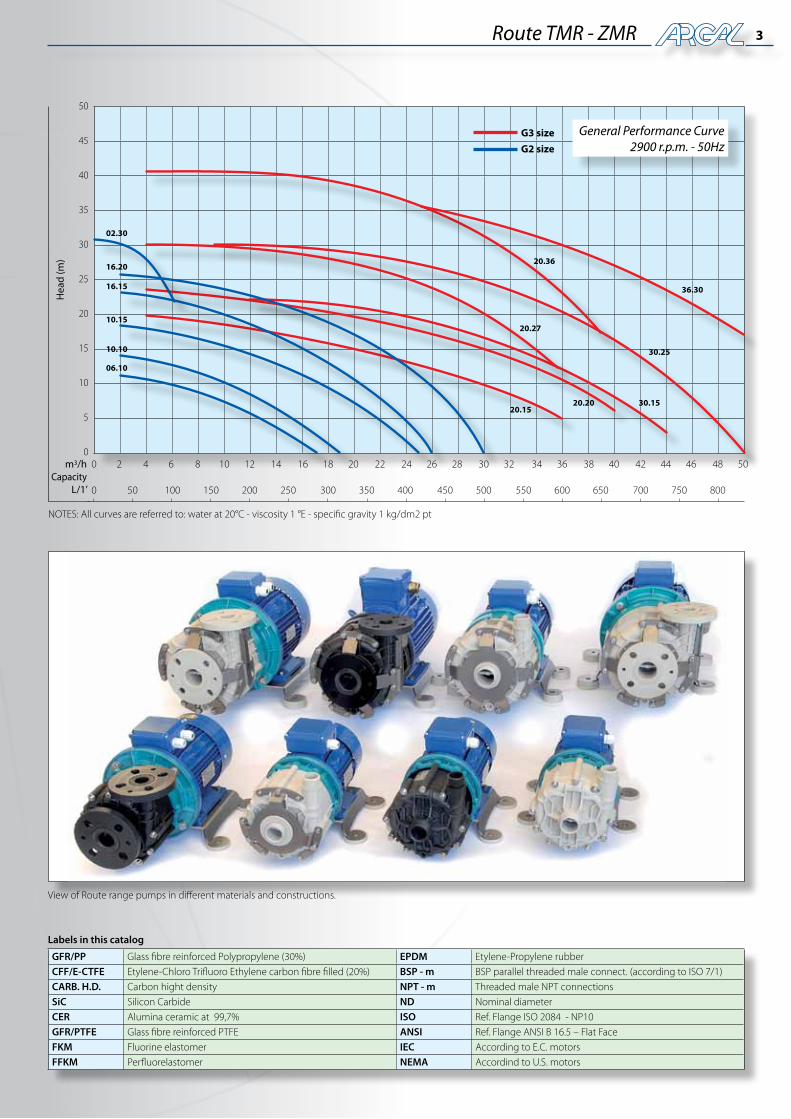
NOTES: All curves are referred to: water at 20°C - viscosity 1 °E - specific gravity 1 kg/dm2 pt
General Performance Curve2900 r.p.m. - 50Hz
36.30
30.25
30.1520.2020.15
20.36
20.27
16.20
02.30
16.15
10.15
10.10
06.10
G2 size
G3 size
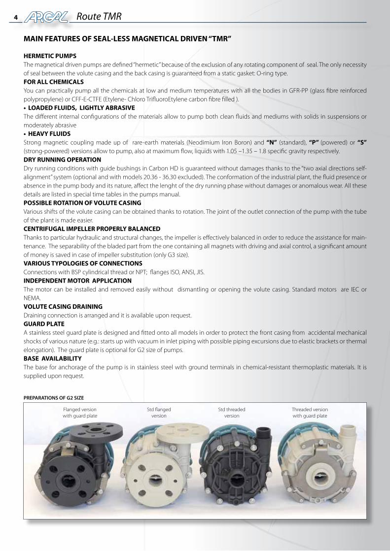
View of Route range pumps in different materials and constructions.
4 Route TMR
MAIN FEATURES OF SEAL-LESS MAGNETICAL DRIVEN “TMR”
HERMETIC PUMPS The magnetical driven pumps are defined “hermetic” because of the exclusion of any rotating component of seal. The only necessity of seal between the volute casing and the back casing is guaranteed from a static gasket: O-ring type. FOR ALL CHEMICALS You can practically pump all the chemicals at low and medium temperatures with all the bodies in GFR-PP (glass fibre reinforced polypropylene) or CFF-E-CTFE (Etylene- Chloro TrifluoroEtylene carbon fibre filled ). • LOADEDFLUIDS,LIGHTLYABRASIVEThe different internal configurations of the materials allow to pump both clean fluids and mediums with solids in suspensions or moderately abrasive • HEAVYFLUIDSStrong magnetic coupling made up of rare-earth materials (Neodimium Iron Boron) and “N” (standard), “P” (powered) or “S” (strong-powered) versions allow to pump, also at maximum flow, liquids with 1.05 –1.35 – 1.8 specific gravity respectively. DRY RUNNING OPERATIONDry running conditions with guide bushings in Carbon HD is guaranteed without damages thanks to the “two axial directions self-alignment” system (optional and with models 20.36 - 36.30 excluded). The conformation of the industrial plant, the fluid presence or absence in the pump body and its nature, affect the lenght of the dry running phase without damages or anomalous wear. All these details are listed in special time tables in the pumps manual. POSSIBLEROTATIONOFVOLUTECASINGVarious shifts of the volute casing can be obtained thanks to rotation. The joint of the outlet connection of the pump with the tube of the plant is made easier. CENTRIFUGALIMPELLERPROPERLYBALANCEDThanks to particular hydraulic and structural changes, the impeller is effectively balanced in order to reduce the assistance for main-tenance. The separability of the bladed part from the one containing all magnets with driving and axial control, a significant amount of money is saved in case of impeller substitution (only G3 size). VARIOUS TYPOLOGIES OF CONNECTIONSConnections with BSP cylindrical thread or NPT; flanges ISO, ANSI, JIS. INDEPENDENT MOTOR APPLICATIONThe motor can be installed and removed easily without dismantling or opening the volute casing. Standard motors are IEC or NEMA. VOLUTE CASING DRAININGDraining connection is arranged and it is available upon request. GUARD PLATEA stainless steel guard plate is designed and fitted onto all models in order to protect the front casing from accidental mechanical shocks of various nature (e.g.: starts up with vacuum in inlet piping with possible piping excursions due to elastic brackets or thermal elongation). The guard plate is optional for G2 size of pumps.BASEAVAILABILITYThe base for anchorage of the pump is in stainless steel with ground terminals in chemical-resistant thermoplastic materials. It is supplied upon request.
PREPARATIONS OF G2 SIZE
Flanged versionwith guard plate
Std flangedversion
Std threadedversion
Threaded versionwith guard plate
5Route TMR
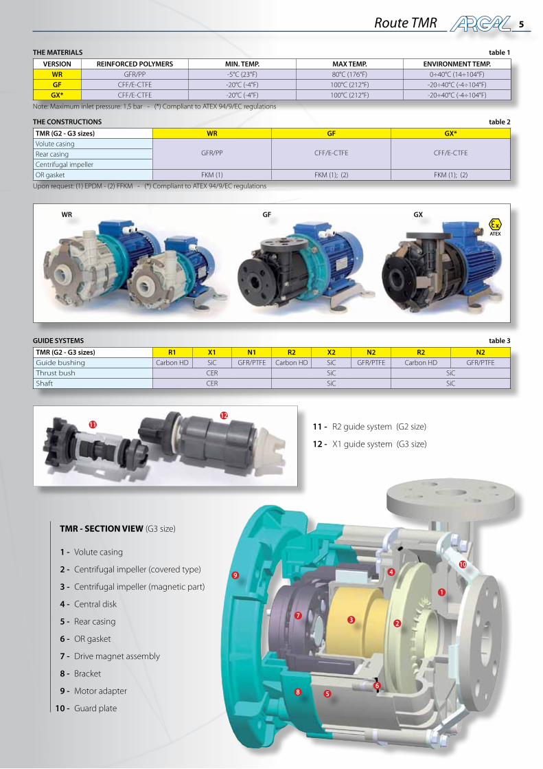
THE MATERIALS table 1
VERSION REINFORCED POLYMERS MIN. TEMP. MAX TEMP. ENVIRONMENT TEMP.WR GFR/PP -5°C (23°F) 80°C (176°F) 0÷40°C (14÷104°F)
GF CFF/E-CTFE -20°C (-4°F) 100°C (212°F) -20÷40°C (-4÷104°F)
GX* CFF/E-CTFE -20°C (-4°F) 100°C (212°F) -20÷40°C (-4÷104°F)
Note: Maximum inlet pressure: 1,5 bar - (*) Compliant to ATEX 94/9/EC regulations
TMR (G2 - G3 sizes) R1 X1 N1 R2 X2 N2 R2 N2Guide bushing Carbon HD SiC GFR/PTFE Carbon HD SiC GFR/PTFE Carbon HD GFR/PTFE
Thrust bush CER SiC SiC
Shaft CER SiC SiC
GUIDE SYSTEMS table 3
THE CONSTRUCTIONS table 2
Upon request: (1) EPDM - (2) FFKM - (*) Compliant to ATEX 94/9/EC regulations
TMR (G2 - G3 sizes) WR GF GX*Volute casing
GFR/PP CFF/E-CTFE CFF/E-CTFERear casing
Centrifugal impeller
OR gasket FKM (1) FKM (1); (2) FKM (1); (2)
WR GF GX
586
10
3
4
72
9
1
11 -
12 -
R2 guide system (G2 size)
X1 guide system (G3 size)
1112
1 -
2 -
3 -
4 -
5 -
6 -
7 -
8 -
9 -
10 -
Volute casing
Centrifugal impeller (covered type)
Centrifugal impeller (magnetic part)
Central disk
Rear casing
OR gasket
Drive magnet assembly
Bracket
Motor adapter
Guard plate
TMR - SECTION VIEW (G3 size)
ATEX
6
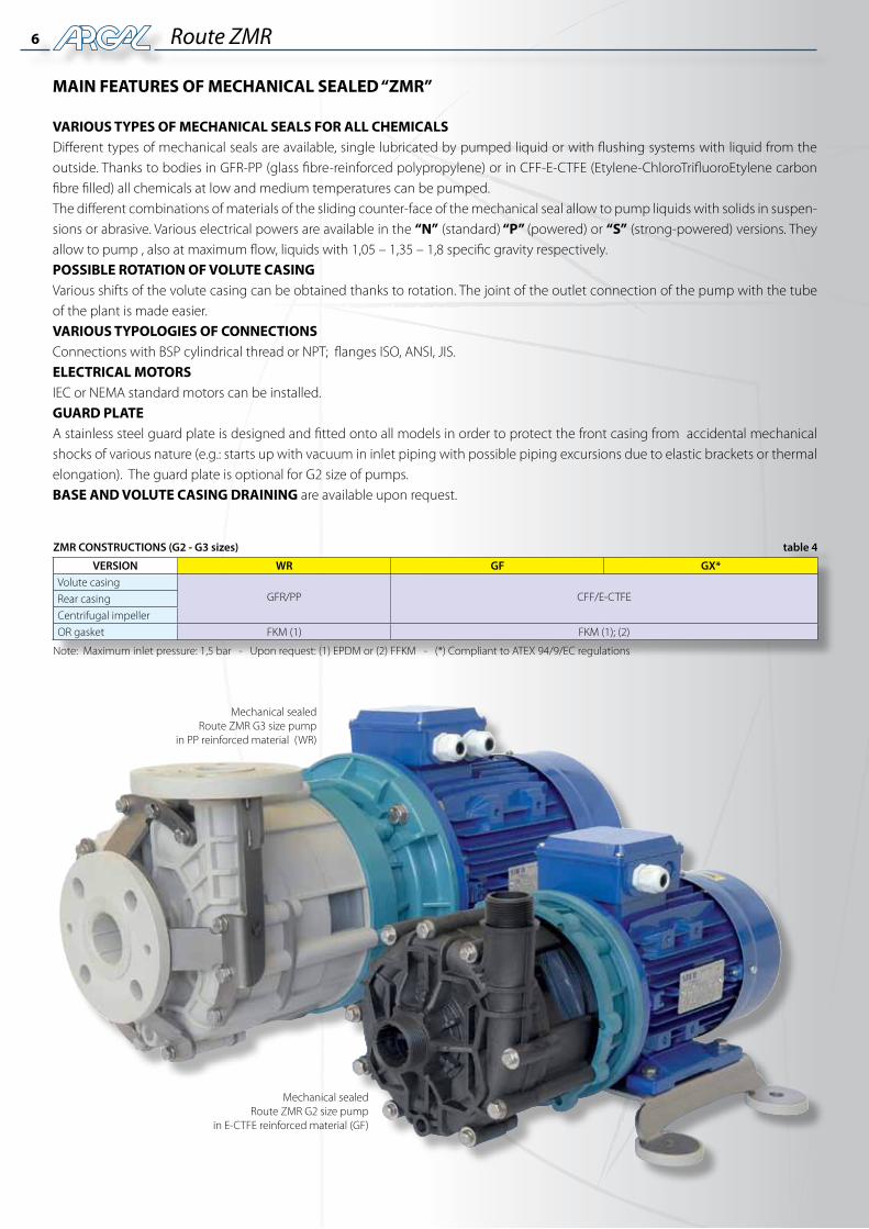
MAIN FEATURES OF MECHANICAL SEALED “ZMR”
VARIOUS TYPES OF MECHANICAL SEALS FOR ALL CHEMICALSDifferent types of mechanical seals are available, single lubricated by pumped liquid or with flushing systems with liquid from the outside. Thanks to bodies in GFR-PP (glass fibre-reinforced polypropylene) or in CFF-E-CTFE (Etylene-ChloroTrifluoroEtylene carbon fibre filled) all chemicals at low and medium temperatures can be pumped.The different combinations of materials of the sliding counter-face of the mechanical seal allow to pump liquids with solids in suspen-sions or abrasive. Various electrical powers are available in the “N” (standard) “P” (powered) or “S” (strong-powered) versions. They allow to pump , also at maximum flow, liquids with 1,05 – 1,35 – 1,8 specific gravity respectively.POSSIBLEROTATIONOFVOLUTECASINGVarious shifts of the volute casing can be obtained thanks to rotation. The joint of the outlet connection of the pump with the tube of the plant is made easier.VARIOUS TYPOLOGIES OF CONNECTIONSConnections with BSP cylindrical thread or NPT; flanges ISO, ANSI, JIS.ELECTRICAL MOTORSIEC or NEMA standard motors can be installed.GUARD PLATEA stainless steel guard plate is designed and fitted onto all models in order to protect the front casing from accidental mechanical shocks of various nature (e.g.: starts up with vacuum in inlet piping with possible piping excursions due to elastic brackets or thermal elongation). The guard plate is optional for G2 size of pumps.BASEANDVOLUTECASINGDRAINING are available upon request.
Route ZMR
table 4
VERSION WR GF GX*Volute casing
GFR/PP CFF/E-CTFERear casing
Centrifugal impeller
OR gasket FKM (1) FKM (1); (2)
Note: Maximum inlet pressure: 1,5 bar - Upon request: (1) EPDM or (2) FFKM - (*) Compliant to ATEX 94/9/EC regulations
ZMR CONSTRUCTIONS (G2 - G3 sizes)
Mechanical sealedRoute ZMR G3 size pump
in PP reinforced material (WR)
Mechanical sealedRoute ZMR G2 size pump
in E-CTFE reinforced material (GF)
7Route ZMR
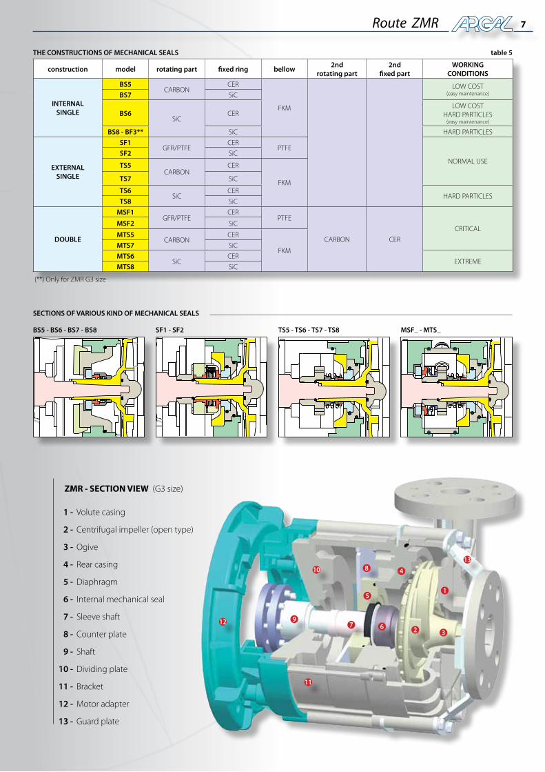
THE CONSTRUCTIONS OF MECHANICAL SEALS table 5
(**) Only for ZMR G3 size
construction model rotating part fixed ring bellow2nd
rotating part2nd
fixed partWORKING
CONDITIONS
INTERNALSINGLE
BS5CARBON
CER
FKM
LOW COST(easy maintenance)BS7 SiC
BS6SiC
CERLOW COST
HARD PARTICLES(easy maintenance)
BS8 - BF3** SiC HARD PARTICLES
EXTERNAL SINGLE
SF1GFR/PTFE
CERPTFE
NORMAL USESF2 SiC
TS5CARBON
CER
FKMTS7 SiC
TS6SiC
CERHARD PARTICLES
TS8 SiC
DOUBLE
MSF1GFR/PTFE
CERPTFE
CARBON CER
CRITICALMSF2 SiC
MTS5CARBON
CER
FKMMTS7 SiC
MTS6SiC
CEREXTREME
MTS8 SiC
BS5 - BS6 - BS7 - BS8 SF1 - SF2 TS5 - TS6 - TS7 - TS8 MSF_ - MTS_
SECTIONS OF VARIOUS KIND OF MECHANICAL SEALS
1 -
2 -
3 -
4 -
5 -
6 -
7 -
8 -
9 -
10 -
11 -
12 -
13 -
Volute casing
Centrifugal impeller (open type)
Ogive
Rear casing
Diaphragm
Internal mechanical seal
Sleeve shaft
Counter plate
Shaft
Dividing plate
Bracket
Motor adapter
Guard plate
ZMR - SECTION VIEW (G3 size)
5
8
6
10
11
13
12
3
4
72
9
1
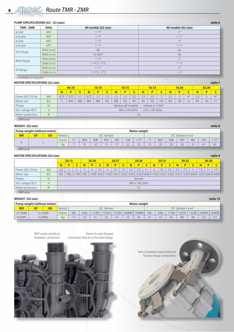
8 Route TMR - ZMR
MOTOR SPECIFICATIONS (G2 size)
MOTOR SPECIFICATIONS (G3 size)
table 7
table 9
06.10 10.10 10.15 16.15 16.20 02.30N P S N P S N P S N P S N P S N P S
Power (IEC) 50 Hz kW 0,55 0,75 1,1 0,75 1,1 1,5 1,1 1,5 2,2 1,5 2,2 3 2,2 3 4* 2,2 3 4*
Motor size IEC 71 80A 80B 80A 80B 90S 80B 90S 90L 90S 90L 100 90L 100 112 90L 100 112
Phases N. 3phase (all models) - 1phase (< 3 kW)
Std. voltage (IEC) V 400 ± 5% 50Hz - 220 ± 5% 50Hz
Motor protection IP 55
20.15 20.20 20.27 20.36 30.15 30.25 36.30N P S N P S N P S N P S N P S N P S N P S
Power (IEC) 50 Hz kW 2,2 3 4 3 4 5,5 4 5,5 7,5 5,5 7,5 11 4 5,5 7,5 5,5 7,5 11 7,5 11 15*
Motor size IEC 90L 100L 112M 100L 112M 132SA 112M 132SA 132SB 132SA 132SB 160MA 112M 132SA 132SB 132SA 132SB 160MA 132SB 160MA 160MB
Phases N. 3phase
Std. voltage (IEC) V 400 ± 5% 50Hz
Motor protection IP 55
PUMP SPECIFICATIONS (G2 - G3 sizes) table 6
TMR - ZMR 50Hz All models (G2 size) All models (G3 size)ø Inlet BSP 1 1/2” 2”
ø Outlet BSP 1 1/4” 1 1/2”
ø Inlet NPT 1 1/2” 2”
ø Outlet NPT 1 1/4” 1 1/2”
ISO flangeDNA (mm) 40 50
DNM (mm) 32 (40*) 40
ANSI flangeDNA (Inch) 1 1/2” 2”
DNM (Inch) 1 1/4” (1 1/2”*) 1 1/2”
JIS flangeDNA (Inch) 1 1/2” 2”
DNM (Inch) 1 1/4” (1 1/2”*) 1 1/2”
WEIGHT (G3 size) table 10
Pump weight (without motor) Motor weightWR GF GX Version IEC 3phase IEC 3phase E-exd
12 (TMR)8 (ZMR
13 (TMR)9 (ZMR)
Frame 90L 100L 112M 132SA 132SB 160MA 160MB 90L 100L 112M 132SA 132SB 160MA 160MB
Kg 17 22 31 53 61 75 85 31 41 65 80 80 155 155
WEIGHT (G2 size) table 8
Pump weight (without motor) Motor weightWR GF GX Version IEC 3phase IEC 3phase E-exd
4 5Frame 71 80A 80B 90S 90L 100 112* 71 80A 80B 90S 90L 100 112*
Kg 7 8 10 13 17 22 31 15 20 20 30 31 41 65
(*) ZMR only
(*) ZMR only
(*) ZMR only
(*) Available on request
“BSP” outlet cylindricalthreaded connection
Detail of outlet flangedconnection directly to the plant flange
View of stainless steel reinforcedflat-face flange connections
9
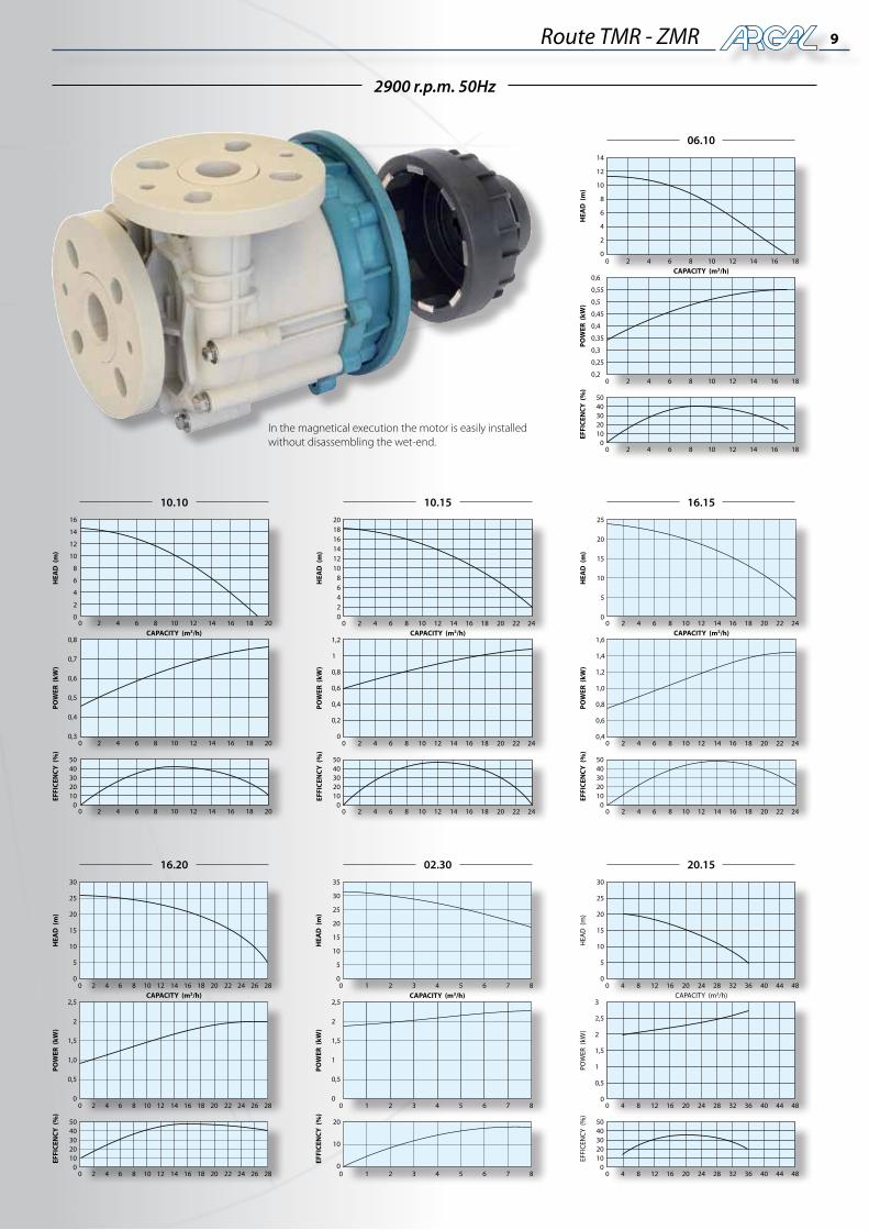
2900 r.p.m. 50Hz
Route TMR - ZMR
In the magnetical execution the motor is easily installedwithout disassembling the wet-end.
06.10
5040302010
0
10.10
5040302010
0
10.15
5040302010
0
16.15
5040302010
0
20.15
5040302010
0
02.30
20
10
0
16.20
5040302010
0
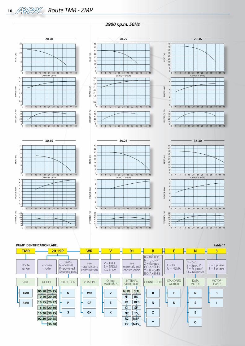
10 Route TMR - ZMR
2900 r.p.m. 50Hz
PUMP IDENTIFICATION LABEL table 11
B = thr. BSPN = thr. NPTZ = flangedISO-ANSI-JISY = fl. 40/40ISO-ANSI-JIS
N = Std.S = Spec. V.E = Ex-proofO = No motor
EXEC.N=normalP=poweredS=strong-pow.
V = FKME = EPDMK = FFKM
seematerials andconstruction
seematerials andconstruction
Routerange
O-ringMATERIALS
INTERNAL STRUCTURE
STANDARDMOTOR
DATAMOTOR
MOTORPHASES
SERIE
TMR N WR V B N 3E
P GF E N S 1U
S GX K Z E
Y O
06.10
10.10
10.15
16.15
16.20
02.30
20.15
20.20
20.27
20.36
30.15
30.25
36.30
GUIDE
N1
R1
X1
N2
R2
X2
SEAL
BS_
BF3
SF_
TS_
MSF_
MTS_
ZMR
MODEL EXECUTION VERSION CONNECTION
TMR 20.15P WR V R1 B E N 3
chosenmodel
E = IECU = NEMA
3 = 3 phase1 = 1 phase
20.36
5040302010
0
36.30
605040302010
0
30.25
605040302010
0
30.15
605040302010
0
20.27
5040302010
0
20.20
5040302010
0
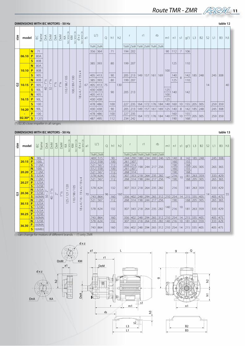
11Route TMR - ZMR
a1 L
r1
DeM
DeA
d x z
KMa1
h2
d x z
KA
L1L3
h3
r m1
rb
s1
s2
B3B2
n1
Qg
g
h2h1
DnA
DnM
(*) 02.30 close impeller in all ranges
size model IEC
fra
me
DnA
DnM DeA
DeM KA
iso
/ an
si /
jis
KMis
o /
ansi
/ ji
s
d x
zis
o /
ansi
/ ji
s
a1L(1)
Q h1 h2r r1 rb
m1 n1 s1 g(1) L3 B2 S2 L1 B3 h3
TMR ZMR TMR ZMR TMR ZMR TMR ZMR
G2
06.10
N 71
40 -
1” ½
32 -
1” ¼
1” ½
1” ¼
110
/ 98
/ 1
05
100
/ 89
/ 1
00
18 x
4 /
16
x 4
/ 19
x 4
67
356 364
75
71
130
194 202
149 157 161 169
90 112 7 106
185 248
14
245 308
40
P 80A
385 393 80 199 207
100
125
8
110S 80B
10.10
N 80A
P 80B
S 90S 405 413 90 205 213 140 142
10.15
N 80B 385 393 80 199 207 125 110
P 90S 405 413
90 205 213 140 142S 90L 430 438 125
16.15
N 90S 405 413 100
P 90L 430 438 125
S 100 478 486 100 227 235 164 172 176 184 140 160 10 155 205 305 259 359
16.20-
02.30*
N 90L 430 438 90 205 213 149 157 161 169 125 140 8 142 185 248 245 308
P 100 478 486 100 227 235164 172 176 184 140
16010
155205 305 259 359
S 112(2) 487 495 112 234 242 190 168
DIMENSIONS WITH IEC MOTORS - 50 Hz table 12
(1) can change for motors of different brands - (2) only ZMR
size model IEC
fra
me
DnA
DnM DeA
DeM KA
iso
/ an
si /
jis
KMis
o /
ansi
/ ji
s
d x
zis
o /
ansi
/ ji
s
a1 L(1) Q h1 h2 r r1 rb m1 n1 s1 g(1) L3 B2 S2 L1 B3 h3
TMR ZMR TMR ZMR TMR ZMR TMR ZMR
G3
20.15N 90L
50 -
2”
40 -
1” ½
2”
1” ½
125
/ 12
1 /
120
110
/ 98
/ 1
05
18 x
4 /
16
- 19
x 4
/ 19
x 4
70
469 515
96
90
160
244 290 188 234 200 246 125 140 8 142 185 248
14
245 308
55
P 100L 512 558 100 261 307
198 244 217 256
140
160
10
155
205 305 265 365S 112M 521 567 112 268 314 190 168
20.20N 100L 512 558 100 261 307 160 155P 112M 521 567 112 268 314 190 168S 132SA 578 624 132 307 353 218 264 235 282 216 181 263 359 333 429
20.27N 112M 521 567 112 268 314 198 244 217 256 190 168 205 305 265 365P 132SA
578 624 132 307 353 218 264 235 282 216 181 263 359 333 429S 132SB
20.36N 132SAP 132SBS 160MA 743 864 160 356 402 248 294 265 312 210 254 14 215 335 405 405 475
30.15N 112M 521 567 112 268 314 198 244 217 256
140
190
10
168 205 305 265 365P 132SA
578 624 132 307 343 218 264 235 282 216 181 263 359 333 429S 132SB
30.25N 132SAP 132SBS 160MA 743 864 160 356 402 248 294 265 312 210 254 14 215 335 405 405 475
36.30
N 132SB 578 624 132 307 353 218 264 235 282 140 216 10 181 263 359 333 429P 160MA
743 864 160 356 402 248 294 265 312 210 254 14 215 335 405 405 475S 160MB(2)
DIMENSIONS WITH IEC MOTORS - 50 Hz table 13

Via Labirinto, 159 - 25125 BRESCIA - ITALYTel. +39.030.3507011 - Fax +39.030.3507077 - Export dpt. Tel. +39.030.3507033
Web: www.argal.it - E-mail: [email protected]
Member of AIBassociazioneindustrialeBresciana
It is the policy of ARGAL to always improve its products and the right is reserved to alter specifications at any time without prior notice.No part of this publication may be reproduced in any form or any means.


![M12 Power - Farnell · Number of positions 4 (3 + PE) 4 5 (4 + PE) 5 (4 + PE) AWG [mm2] 0,5 – 1,5 0,5 – 1,5 0,75 – 2,5 0,75 – 2,5 AWG 20 – 16 AWG 20 – 16 AWG 18 – 14](https://img.pdfslide.net/doc/110x75/5f0685397e708231d4186643/m12-power-number-of-positions-4-3-pe-4-5-4-pe-5-4-pe-awg-mm2-05.jpg)