Embed Size (px)
Citation preview

CNC Router PartsRouter Mount
Assembly InstructionsVersion 2016Q3.1

Router Mount Assembly CONTENTS
Contents
1 Base Adapter Installation, Routers or Round Spindles 3
2 Base Adapter Installation, Air-Cooled Spindle 11
3 Tramming Plate Installation 14
Router Mount AssemblyVersion 2016Q3.1
Copyright©2016 CNC Router Parts LLC.All Rights Reserved. 2

Router Mount Assembly
1
Base Adapter Installation, Routers or RoundSpindles
Note: If you purchased a spindle from CNC Router Parts, skip to section 2.
Router Mount AssemblyVersion 2016Q3.1
Copyright©2016 CNC Router Parts LLC.All Rights Reserved. 3

Router Mount Assembly
CRP144-03 Base Adapter
CRP142-XX Router Mount
M5 x 20mm Socket Head Cap Screw
• Attach the router mount to the base adapter as indicated
Router Mount AssemblyVersion 2016Q3.1
Copyright©2016 CNC Router Parts LLC.All Rights Reserved. 4

Router Mount Assembly
• Tighten the highlighted fasteners.
Router Mount AssemblyVersion 2016Q3.1
Copyright©2016 CNC Router Parts LLC.All Rights Reserved. 5

Router Mount Assembly
M8 Roll In T-Nut
M8 x 16mm Socket Head Cap Screw
Note: If you purchased the optional tramming plate, skip this step and proceedto section 3.
• Thread the socket head cap screws into the t-nuts through the base adapter asindicated
Router Mount AssemblyVersion 2016Q3.1
Copyright©2016 CNC Router Parts LLC.All Rights Reserved. 6

Router Mount Assembly
• Slide the router mount assembly into the t-slots of the z axis as indicated.
Router Mount AssemblyVersion 2016Q3.1
Copyright©2016 CNC Router Parts LLC.All Rights Reserved. 7

Router Mount Assembly
• Tighten the highlighted fasteners.
Router Mount AssemblyVersion 2016Q3.1
Copyright©2016 CNC Router Parts LLC.All Rights Reserved. 8

Router Mount Assembly
• Slide your router or round spindle into the router mount as indicated.
Router Mount AssemblyVersion 2016Q3.1
Copyright©2016 CNC Router Parts LLC.All Rights Reserved. 9

Router Mount Assembly
• Tighten the highlighted fasteners.
Router Mount AssemblyVersion 2016Q3.1
Copyright©2016 CNC Router Parts LLC.All Rights Reserved. 10

Router Mount Assembly
2
Base Adapter Installation, Air-Cooled Spindle
Router Mount AssemblyVersion 2016Q3.1
Copyright©2016 CNC Router Parts LLC.All Rights Reserved. 11
Router Mount Assembly
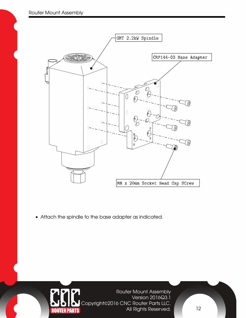
GMT 2.2kW Spindle
CRP144-03 Base Adapter
M8 x 20mm Socket Head Cap SCrew
• Attach the spindle to the base adapter as indicated.
Router Mount AssemblyVersion 2016Q3.1
Copyright©2016 CNC Router Parts LLC.All Rights Reserved. 12
Router Mount Assembly
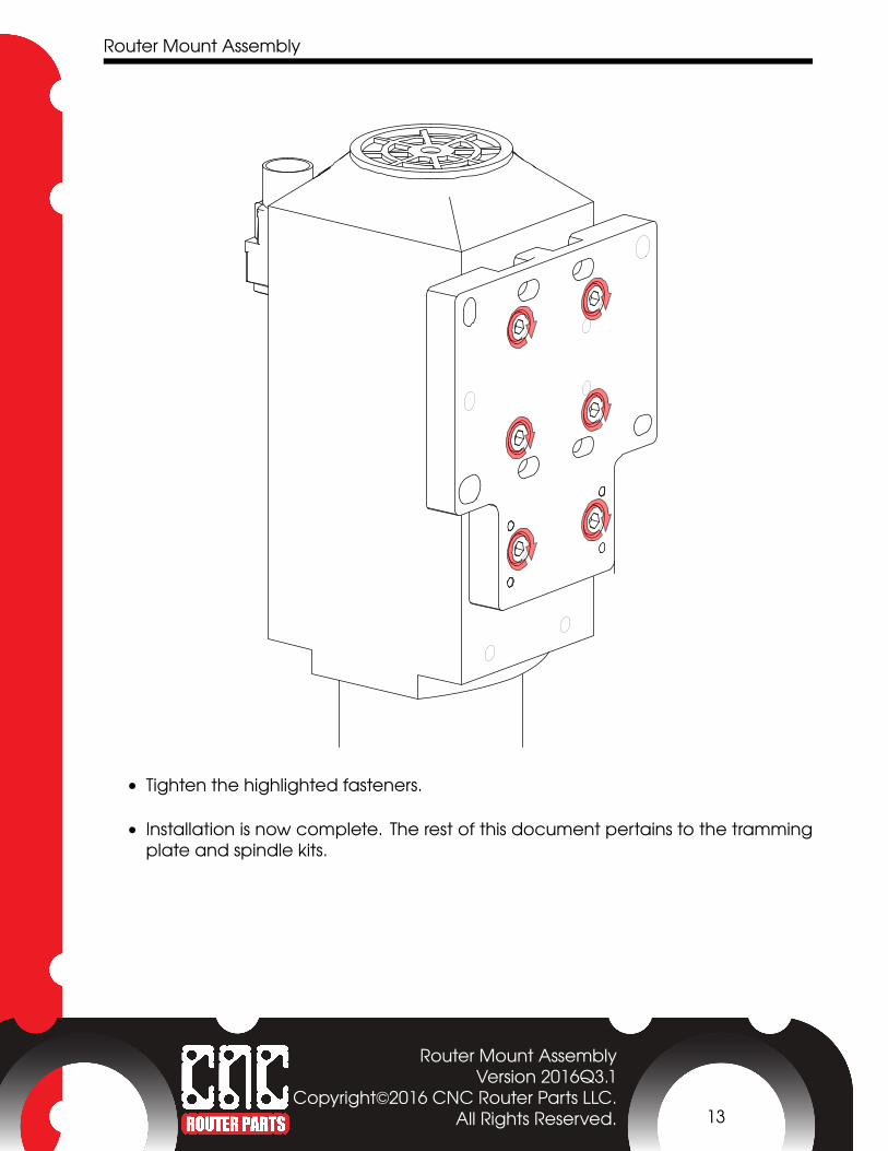
• Tighten the highlighted fasteners.
• Installation is now complete. The rest of this document pertains to the trammingplate and spindle kits.
Router Mount AssemblyVersion 2016Q3.1
Copyright©2016 CNC Router Parts LLC.All Rights Reserved. 13

Router Mount Assembly
3
Tramming Plate Installation
Router Mount AssemblyVersion 2016Q3.1
Copyright©2016 CNC Router Parts LLC.All Rights Reserved. 14

Router Mount Assembly
M8 Roll In T-Nut
CRP144-01 Tramming Plate
M8 x 16 mm Socket Head Cap Screw
• Thread the socket head cap screws into the t-nuts through the tramming as indi-cated
Router Mount AssemblyVersion 2016Q3.1
Copyright©2016 CNC Router Parts LLC.All Rights Reserved. 15

Router Mount Assembly
• Slide the tramming plate into the t-slots of the z axis as indicated.
Router Mount AssemblyVersion 2016Q3.1
Copyright©2016 CNC Router Parts LLC.All Rights Reserved. 16

Router Mount Assembly
• Tighten the highlighted fasteners.
Router Mount AssemblyVersion 2016Q3.1
Copyright©2016 CNC Router Parts LLC.All Rights Reserved. 17

Router Mount Assembly
M8 x 30 Socket Head Cap Screw
M8 Shoulder Bolt 10mm x 16mm
B3X Eccentric BearingM8 x 35 Socket Head Cap Screw
Note: Skip this step if you purchased the spindle kit.
• Attach the router mount assembly to the tramming plate as indicated.
Router Mount AssemblyVersion 2016Q3.1
Copyright©2016 CNC Router Parts LLC.All Rights Reserved. 18

Router Mount Assembly
Note: Skip this step if you purchased the spindle kit.
• Slide your router or round spindle into the router mount as indicated.
Router Mount AssemblyVersion 2016Q3.1
Copyright©2016 CNC Router Parts LLC.All Rights Reserved. 19

Router Mount Assembly
Note: Skip this step if you purchased the spindle kit.
• Tighten the highlighted fasteners.
Router Mount AssemblyVersion 2016Q3.1
Copyright©2016 CNC Router Parts LLC.All Rights Reserved. 20

Router Mount Assembly
M8 Shoulder Bolt 10mm x 16mm
M8 x 30 Socket Head Cap Screw
B3X Eccentric BearingM8 x 35 Socket Head Cap Screw
Note: Skip this step if you did not purhcase a spindle kit.
• Attach the spindle assembly to the tramming plate as indicated.
Router Mount AssemblyVersion 2016Q3.1
Copyright©2016 CNC Router Parts LLC.All Rights Reserved. 21

Router Mount Assembly
M8 Dowel Pin
Note: The router mount and or spindle are hidden for the remainder of theseinstructions for visual clarity.
• Slide the M8 dowel pin to set the router mount in the nominally trammed position.
Router Mount AssemblyVersion 2016Q3.1
Copyright©2016 CNC Router Parts LLC.All Rights Reserved. 22

Router Mount Assembly
• Tighten the highlighted fasteners.
• Remove the dowel pin.
Router Mount AssemblyVersion 2016Q3.1
Copyright©2016 CNC Router Parts LLC.All Rights Reserved. 23

Router Mount Assembly
• After completing test cuts, you may slightly loosen all four of the mounting fas-teners, and rotate the eccentric bearing to adjust your tram.
Router Mount AssemblyVersion 2016Q3.1
Copyright©2016 CNC Router Parts LLC.All Rights Reserved. 24

Router Mount Assembly
• In most installation, tram does not need to be adjusted around the axis parallelto the gantry of the machine. However, if adjustment is required in this direction,a small shim can be placed between the tramming plate and the base adapter,at the top or bottom as needed.
Router Mount AssemblyVersion 2016Q3.1
Copyright©2016 CNC Router Parts LLC.All Rights Reserved. 25