Embed Size (px)
Citation preview

Routing Centrifugal Compressor Seal Oil De-gassing Emissions
to Fuel Gas as an Alternative to Installing Dry Seals
Global Methane Initiative All-Partnership Meeting
Oil and Gas Subcommittee – Technical and Policy Sessions
October 14, 2011
Krakow, Poland
Reid Smith BP,
Senior GHG and Air Quality Advisor
1
Agenda Natural Gas STAR Program Background Centrifugal Compressor Wet Seals Retrofitting/Installing Dry Seals Background and Summary of North Slope Study Overview of North Slope Operations
Central Gas Facility Central Compressor Plant
Sour Seal Oil Vapor Recovery System Early Results: BP Measurements of CCP Preliminary Results: Velocity Measurements Applicability/Benefits Conclusions and Next Steps Contact Information

2
Natural Gas STAR Program Background The Natural Gas STAR Program is a flexible, voluntary partnership with oil and natural gas companies—both in the United States and internationally to promote cost-effective technologies and practices that reduce emissions of methane. The main goal of Natural Gas STAR is to work with Partner companies to develop technical information and then facilitate the implementation of mitigation practices across the industry. As both a potent greenhouse gas and clean energy source, reducing methane emissions has both environmental and economic benefits. BP has been an active Partner since 1995, contributing to the Natural Gas STAR Program’s technical information and technology transfer efforts.

3
Centrifugal Compressor Wet Seals High pressure seal oil circulates between rings around the compressor shaft Oil absorbs the gas on the inboard side
Little gas leaks through the oil seal Seal oil degassing vents methane to the atmosphere
Source: PEMEX
• Wet seals leak little gas at the seal face
• Most emissions are from seal oil degassing
• Seal oil degassing may vent 1.1 to 5.7 m3/minute
• One Natural Gas STAR Partner reported emissions as high as 2,124 m3/day

4
Traditional Solution: Retrofitting/Installing Dry Seals
Dry seals keep gas from escaping while rotating with the shaft Tandem dry seals
• Dry seals: • 0.8 to 5.1 m3/hour (0.01 to 0.08 m3/ minute) leak rate • Significantly less than the 1.1 to 5.7 m3/minute emissions from wet
seals • Very cost-effective option for new compressors • Significant capital costs and downtime for retrofitting compressors
• See Lessons Learned for more info • Alternative exists for more cost-effective seal oil degassing and vapor
recovery retrofit with less downtime

5
Background of North Slope Study Natural Gas STAR learned of anecdotal information on this potential mitigation opportunity a few years back
Developed a theoretical example and presented to Natural Gas STAR Partners at workshops and in the Spring 2009 Newsletter
In taking measurements, BP discovered their wet seal recovery system on centrifugal compressors at its North Slope facilities
BP’s initial results showed recovery of >99% of seal oil gas that would be otherwise vented to atmosphere from degassing tank
Led to BP and Natural Gas STAR collaboration on detailed measurement study of alternative wet seal capture mitigation opportunity
Recovery system that separates gas from the sour seal oil before being sent to the degassing tank Recovered gas sent to various outlets: flare, low pressure fuel, turbine fuel ~273 psig (18.6 Bar), compressor suction System leads to lower emissions from degassing tank vent (more details on following slide)

6
Summary of North Slope Study Purpose:
Evaluate methane emissions capture from sour seal oil vapor recovery systems on centrifugal compressors at the North Slope. Systems show evidence of reducing wet seal degassing emissions.
The Team: • Natural Gas STAR • BP local and global staff • North Slope facility operators • North Slope emissions
measurement specialists
The Tools: • In-depth understanding of compressor wet seal
recovery system design and layout • FLIR IR camera • Vent anemometer • P&IDs and operational data • Complete readouts of compressor operating conditions
and key parameters
Goals: A detailed evaluation and review of all sour seal oil recovery systems on the North Slope with: • Real-time measurement data from one facility (CCP) • Engineering calculations from CGF and other facilities as
applicable Comprehensive characterization of wet seal degassing recovery system including process/operating requirements, applicability, limitations, emission reduction potential, costs, and economics.
This presentation is focusing on preliminary results from Central Compressor Plant (CCP) only; final results will be available at a later date.

7
Overview of North Slope Operations

8
Overview of North Slope Operations
Prudhoe Bay process flow and volumes
~100 Centrifugal Compressors All but a few with Wet Seals All Wet Seal machines equipped with recovery system Pressures: 3 psi suction => 4,700 psi discharge

9
Overview of North Slope Operations
Key facilities visited
Start of TAPS

10
Central Gas Facility (CGF) World’s largest gas processing plant (max feed of 246 MMcm/day) Processes all gas from Prudhoe Bay gathering & boosting stations (except local fuel) Products:
Residue gas Natural gas liquids (blended with oil and delivered to TAPS) Miscible injectant (used for EOR purposes)
11 compressors (totaling over 500,000 HP) Three boosters Two refrigerant Two MI Four tandems
Seal oil vapor recovery lines sent to flare

11
Central Compressor Plant (CCP) World’s largest compressor station (~238 MMcm/day capacity) Receives residue gas from CGF, compresses to higher pressures, and sends to gas injection wellpads (~200 MMcm/day at 3,600 to 4,000 psig) 15 compressors (totaling 537,000 HP)
Nine low pressure (1st stage) compressors in parallel Four high pressure (2nd stage) compressors in parallel Two tandem compressors (1st and 2nd stages) in parallel
Seal oil vapor recovery lines sent to flare or fuel gas (for compressor turbines, heaters, and blanket gas)

12
Sour Seal Oil Vapor Recovery System
4 OPTIONS
FLARE
1.8 atm
4.4 atm
18.0 atm Boiler
Low pressure fuel gas
Compressor turbine fuel
Seal oil circulation pump
New fuel pressure seal oil degassing drum and demister (“sour seal oil trap”)
Less gas vented to atmosphere
Atmospheric seal oil degassing drum
*Note: New equipment in red*
Seal oil discharge pressure = 96.3 atm
Compressor Suction/recycle
13
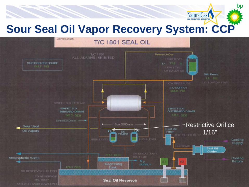
Sour Seal Oil Vapor Recovery System: CCP
Restrictive Orifice 1/16”
14
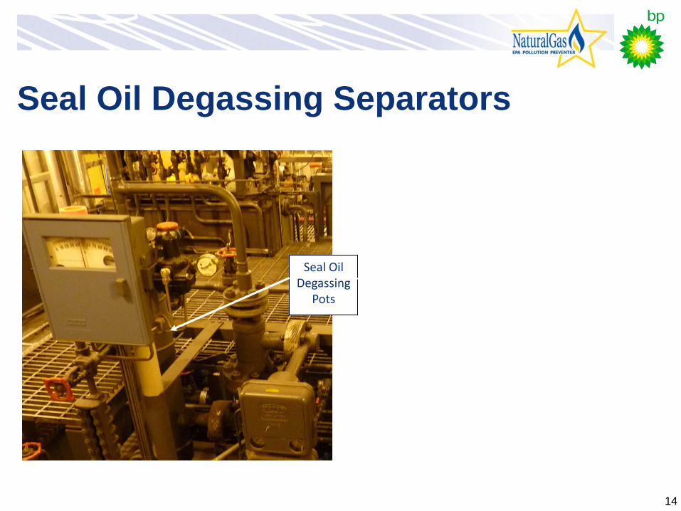
Seal Oil Degassing Separators
Seal Oil Degassing
Pots

15
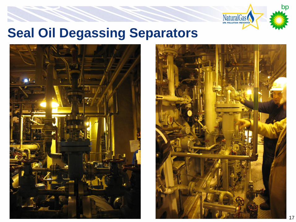
Seal Oil Degassing Separators

16
Seal Oil Degassing Separator/System
Restrictive Orifice (note frost from expansion cooling
17
Seal Oil Degassing Separators

18
CCP Fuel Gas Layout
19
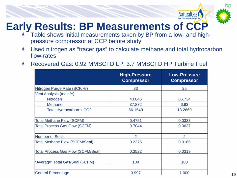
Early Results: BP Measurements of CCP Table shows initial measurements taken by BP from a low- and high-pressure compressor at CCP before study Used nitrogen as “tracer gas” to calculate methane and total hydrocarbon flow-rates Recovered Gas: 0.92 MMSCFD LP; 3.7 MMSCFD HP Turbine Fuel
High-Pressure Compressor
Low-Pressure Compressor
Nitrogen Purge Rate (SCF/Hr) 33 25 Vent Analysis (mole%)
Nitrogen 43.846 86.734 Methane 37.872 6.93 Total Hydrocarbon + CO2 56.1540 13.2660
Total Methane Flow (SCFM) 0.4751 0.0333 Total Process Gas Flow (SCFM) 0.7044 0.0637
Number of Seals 2 2 Total Methane Flow (SCFM/Seal) 0.2375 0.0166
Total Process Gas Flow (SCFM/Seal) 0.3522 0.0319 “Average" Total Gas/Seal (SCFM) 108 108 Control Percentage 0.997 1.000

20
Preliminary Results: Velocity Measurements Table shows vane anemometer measurements taken prior to and during the study Full results of study are not yet final, but initial results from CCP measurements show generally consistent with BP’s results from before the study
CCP Velocity Readings - During Study
Facility Compressor Tag Compressor description # of Seals per Tank Vent size
1 Min Mean
1 Min Mean
1 Min Mean
Vent Area ft2 fpm scf/min
N2 Purge scf/min
in m/s m/s m/s CCP K-18-1801 1st Stage Injection comp Degassing Tank Vent 2 2 0.36 0.38 0.28 0.022 66.9 1.5
Seal Oil Reservoir Vent 4 0.35 0.34 0.37 0.087 69.5 6.1
CCP K-18-1809 2nd Stage Injection comp Degassing Tank Vent 2 2 0.42 0.4 0.2 0.022 66.9 1.5
Seal Oil Reservoir Vent 4 0.6 0.57 0.81 0.087 129.9 11.3
Velocity Readings - Prior to Study
END K-E3-1510/20/30A
Main A (1st, 2nd, 3rd stages) Degassing Tank Vent 6 2 0.86 0.8 0.48 0.022 140.4 3.1
END K-E3-1510/20/30A second vent Degassing Tank Vent 6 6 0.87 0.52 0.71 0.196 137.8 27.1
30.1
END K-E3-1510/20/30B
Main B (1st, 2nd, 3rd stages) Degassing Tank Vent 6 2 3.84 3.5 3.15 0.022 688.1 15.0
END K-E3-1510/20/30B second vent Degassing Tank Vent 6 6 2.68 2.14 4.67 0.196 622.5 122.3
137.3
END C-1501/02B Booster B (1st & 2nd stages) Degassing Tank Vent 2 2 0.64 0.42 0.67 0.022 113.5 2.5
END C-1501/02B second vent Degassing Tank Vent 2 2 0.54 0.39 0.46 0.021825 91.2 2.0 4.5
LPC K-52-1807 Reinjection Compressors Degassing Tank Vent 2 2 0.82 0.91 0.83 0.022 167.9 3.7 LPC K-52-1808 Reinjection Compressors Degassing Tank Vent 2 1.44 1.73 1.6 0.022 312.9 6.8 LPC K-42-1801 STV/IP Compressors Degassing Tank Vent 2 2 0.82 0.93 1.06 0.022 184.3 4.0 LPC K-42-1801 Second vent Degassing Tank Vent 4 0.96 0.58 0.52 0.087 135.1 11.8 15.8
CCP K-18-1801 1st Stage Injection comp Degassing Tank Vent 2 2 0.3 0.33 0.32 0.022 62.3 1.4 CCP K-18-1802 1st Stage Injection comp Degassing Tank Vent 2 2 0.54 0.56 0.45 0.022 101.7 2.2 CCP K-18-1803 1st Stage Injection comp Degassing Tank Vent 2 2 0.45 0.15 0.19 0.022 51.8 1.1 CCP K-18-1804 1st Stage Injection comp Degassing Tank Vent 2 2 0.05 0.17 0.06 0.022 18.4 0.4 CCP K-18-1805 1st Stage Injection comp Degassing Tank Vent 2 2 2.65 2.67 2.52 0.022 514.3 11.2 CCP K-18-1806 1st Stage Injection comp Degassing Tank Vent 2 2 0.38 0.74 0.56 0.022 110.2 2.4 CCP K-18-1807 1st Stage Injection comp Degassing Tank Vent 2 2 0 0.04 0.22 0.022 17.1 0.4 CCP K-18-1808 1st Stage Injection comp Degassing Tank Vent 2 2 0.2 0.09 0.09 0.022 24.9 0.5 CCP K-18-1813 1st Stage Injection comp Degassing Tank Vent 2 2 0.54 0.64 0.65 0.022 120.0 2.6
CCP K-18-1809 2nd Stage Injection comp Degassing Tank Vent 2 2 0.54 0.42 0.29 0.022 82.0 1.8
CCP K-18-1810 2nd Stage Injection comp Degassing Tank Vent 2 2 1.17 0.46 0.34 0.022 129.2 2.8
CCP K-18-1811 2nd Stage Injection comp Degassing Tank Vent 2 2 1.44 1.38 0.59 0.022 223.7 4.9
CCP K-18-1812 2nd Stage Injection comp Degassing Tank Vent 2 2 0.38 0.43 0.4 0.022 79.4 1.7
CGF K-19-1802A/B Booster #2 Degassing Tank Vent 2 3 0.26 0.31 0.93 0.049 98.4 4.8 CGF K-19-1802A/B Second vent Degassing Tank Vent 3 0.36 0.25 0.82 0.049 93.8 4.6 9.4 CGF K-19-1805 MI Compressor Degassing Tank Vent 2 2 0.49 0.4 0.38 0.022 83.3 1.8 CGF K-19-1805 Second vent Degassing Tank Vent 2 9.98 9.55 9.77 0.022 1922.1 42.0 43.8

21
CCP Compressor Vent Measurement

22
Close-up

23
FLIR Camera Verification

24
Applicability/Benefits to Oil and Gas Companies
Based on the results of this study, this sour seal oil vapor recovery system could prove to be an economic alternative to dry seal retrofits on centrifugal compressors
Dry seals on new compressors are now more prevalent in industry—typically cheaper than wet seals Dry seal retrofits on older compressors are still very high in cost; ~$250,000 to $1 million per compressor Sour seal oil vapor recovery system on wet seals compressors much lower in capital cost, requires short-duration compressor shutdown or interruption in gas service
Project characterization could provide companies with a way to both reduce methane emissions and utilize recovered gas cost-effectively

25
Applicability/Benefits Investment includes cost of:
Intermediate degassing drum (“sour seal oil trap”) New piping Gas demister/filter Pressure regulator for fuel gas line
Project summary: Less expensive capital costs compared to dry seals Prevents most seal oil gas emissions from venting to atmosphere while also improving site efficiency Positive cash flow after less than a month
PROJECT SUMMARY: CAPTURE AND USE OF SEAL OIL DEGASSING EMISSIONS
Operating Requirements
Centrifugal compressor with seal oil system Nearby use for low pressure fuel gas New intermediate pressure flash drum, fuel filter, pressure regulator
Capital & Installation Costs
$22,0001
Annual Labor & Maintenance Costs
Minimal
Methane saved 1.8 million m3
Gas Price per Mcm $105 $175 $250
Value of Gas Saved $189,000 $315,000 $450,000
Payback Period in Months 1.4 0.8 0.6
1Assuming a typical seal oil flow rate of 14.20 liters/minute (3.75 gallons/minute)

26
Conclusions and Next Steps Preliminary results are promising and indicate that sour seal oil vapor recovery from centrifugal compressors can be a viable project option for companies BP and Natural Gas STAR currently analyzing data obtained during study BP and Natural Gas STAR will continue to collaborate on this study to fully characterize the seal oil vapor recovery system seen on the North Slope Team to publish more detailed results of study in a future article

27
Contact Information For further details, direct questions to:
Suzie Waltzer EPA Natural Gas STAR Program [email protected] +1 (202) 343-9544
Reid Smith BP [email protected] +1 (281) 384-3583
Don Robinson ICF International [email protected] +1 (703) 218-2512