Embed Size (px)
Citation preview
RPMX/RPMSP-D132URPMSP-D180U
S E T U P G U I D E
020-100246-02

RPMX/RPMSP-D132URPMSP-D180U
S E T U P G U I D E
020-100246-02
NOTICE This equipment has been tested and found to comply with the limits for a Class A digital device, pursuant to Part 15 of the FCC Rules. These lim-its are designed to provide reasonable protection against harmful interference when the equipment is operated in a commercial environment. This equipment generates, uses, and can radiate radio frequency energy and, if not installed and used in accordance with the instruction manual, may cause harmful interference to radio communications. Operation of this equipment in a residential area is likely to cause harmful interference in which case the user will be required to correct the interference at his own expense.
This Class A digital apparatus complies with Canadian ICES-003. Cet appareil numérique de la classe A est conforme à la norme NMB-003 du Canada.
.
The equipment is designed and manufactured with high-quality materials and components that can be recycled and reused.
This symbol means that electrical and electronic equipment, at their end-of-life, should be disposed of separately from regular waste. Please dispose of this equipment appropriately and according to local regulations. In the European Union, there are separate collection systems for used electrical and electronic products. Please help us to conserve the environment we live in!
Copyright © 2008-2010 Christie Digital Systems USA, Inc. All rights reserved. All brand names and product names are trademarks, registered trademarks or trade names of their respective holders. Canadian manufacturing facility is ISO 9001 and 14001 certified. Performance specifica-tions are typical, but may vary depending on conditions beyond Christie's control such as maintenance of the product in proper working condi-tions. Performance specifications are based on information available at the time of printing. Every effort has been made to ensure accuracy, however in some cases changes in the products or availability could occur which may not be reflected in this document. Christie reserves the right to make changes without notice or obligation.
WARRANTYFor complete information about Christie’s limited warranty, please contact your Christie Dealer. In addition to the other limitations that may be specified in Christie’s limited warranty, the warranty does not cover: (a) Damage occurring during shipment, in either direction. (b) Projector lamps (See Christie’s separate lamp program policy). (c) Damage caused by use of a projector lamp beyond the recommended lamp life, or use of a lamp supplied by a supplier other than Christie. (d) Problems caused by combination of the equipment with non-Christie equipment, such as distribution systems, cameras, video tape record-
ers, etc., or use of the equipment with any non-Christie interface device. (e) Damage caused by misuse, improper power source, accident, fire, flood, lightening, earthquake or other natural disaster. (f) Damage caused by improper installation/alignment, or by equipment modification, if by other than Christie service personnel. (g) For LCD projectors, the warranty period specified applies only where the LCD projector is in ‘normal use. “Normal use” means the LCD pro-
jector is not used more than 8 hours a day, 5 days a week. For any LCD projector where ‘normal use” is exceeded, warranty coverage under this warranty terminates after 6000 hours of operation.
(h) Failure due to normal wear and tear.
PREVENTATIVE MAINTENANCEPreventative maintenance is an important part of the continued and proper operation of your projector. Please see the Maintenance section for specified maintenance items as they relate to your projector and/or model. Failure to perform maintenance as required, and in accordance with the maintenance schedule specified by Christie, will void the warranty.
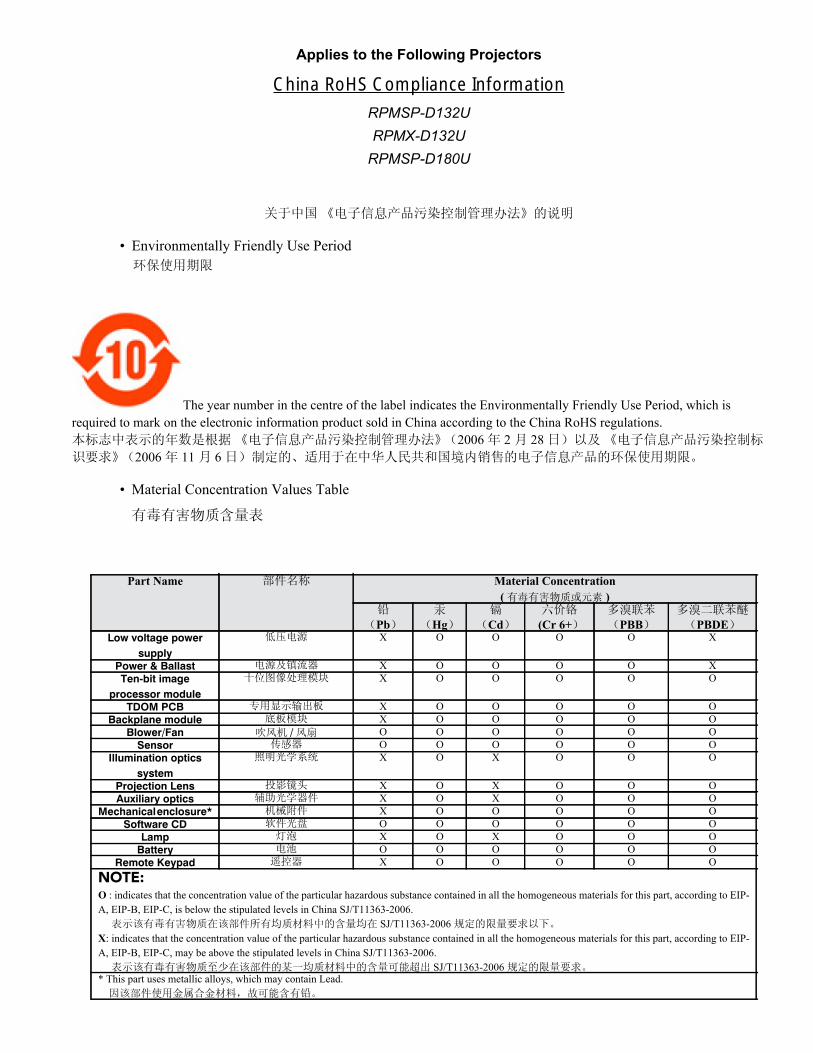
Applies to the Following Projectors
China RoHS Compliance Information
• Environmentally Friendly Use Period
The year number in the centre of the label indicates the Environmentally Friendly Use Period, which is required to mark on the electronic information product sold in China according to the China RoHS regulations.
2006 2 282006 11 6
• Material Concentration Values Table
Part Name Material Concentration( )
Pb Hg Cd (Cr 6+ PBB PBDELow voltage power
supply
X O O O O X
Power & Ballast X O O O O XTen-bit image
processor module
X O O O O O
TDOM PCB X O O O O OBackplane module X O O O O O
Blower/Fan / O O O O O OSensor O O O O O O
Illumination optics system
X O X O O O
Projection Lens X O X O O OAuxiliary optics X O X O O O
Mechanical enclosure* X O O O O OSoftware CD O O O O O O
Lamp X O X O O OBattery O O O O O O
Remote Keypad X O O O O ONOTE:O : indicates that the concentration value of the particular hazardous substance contained in all the homogeneous materials for this part, according to EIP-A, EIP-B, EIP-C, is below the stipulated levels in China SJ/T11363-2006. SJ/T11363-2006X: indicates that the concentration value of the particular hazardous substance contained in all the homogeneous materials for this part, according to EIP-A, EIP-B, EIP-C, may be above the stipulated levels in China SJ/T11363-2006. SJ/T11363-2006* This part uses metallic alloys, which may contain Lead.
RPMSP-D132URPMX-D132URPMSP-D180U

Table of Contents
1: Introduction
1.1 Purchase Record and Service Contacts .......................................................................................1-11.1.1 Purchase Record ..................................................................................................................1-1
1.2 Key Features ................................................................................................................................1-11.3 Components .................................................................................................................................1-21.4 Additional Tools Required ..........................................................................................................1-21.5 General Precautions .....................................................................................................................1-2
1.5.1 AC /Power Precautions........................................................................................................1-31.5.2 Lamp Precautions ................................................................................................................1-31.5.3 Labels and Markings............................................................................................................1-3
2: Installation and Setup
2.1 Projector Quick Setup and Installation ........................................................................................2-1Step 1 Unpacking the projector ............................................................................................2-1Step 2 Modifying projector configuration (if required) ........................................................2-2Step 3 Calculating throw distance, position and mount projector Throw Distance .............2-4Throw Distance .....................................................................................................................2-4Lifting and transporting the projector ...................................................................................2-6Mounting .............................................................................................................................2-6Step 4 Connecting sources ....................................................................................................2-6Step 5 Turning the projector ON and selecting a source ......................................................2-6Step 6 Adjusting the projection lens .....................................................................................2-7 Lock lens adjustments to prevent unnecessary tampering. ..................................................2-7Step 7 Adjusting image geometry using the 6-axis adjuster ................................................2-7Step 8 Adjusting image ........................................................................................................2-8
2.2 Connecting Sources .....................................................................................................................2-8RGB signals (5 BNCs) ........................................................................................................2-9YPbPr signals .......................................................................................................................2-10DVI Digital Video ................................................................................................................2-10Composite and S-Video ........................................................................................................2-11Extra Video ...........................................................................................................................2-11Optional Inputs .....................................................................................................................2-12
2.3 Connecting Communications ......................................................................................................2-122.3.1 Remote Keypad....................................................................................................................2-122.3.2 Serial Port Connections .......................................................................................................2-12
Connecting RS-232 ...............................................................................................................2-12Connecting RS-422 ...............................................................................................................2-13
2.3.3 Ethernet Communications....................................................................................................2-132.3.4 Connecting Multiple Projectors ...........................................................................................2-14
RS-232 Network ...................................................................................................................2-14Mixed Network .....................................................................................................................2-14
2.3.5 Etherenet Network Setup .....................................................................................................2-15Setting the Projector’s IP Address ........................................................................................2-16Changing the Port Number ...................................................................................................2-16Subnet Mask and Default Gateway ......................................................................................2-16
RPMX/RPMSP-D132U & RPMSP-D180U Setup Guide i020-100246-02 Rev. 1 (10-2010)
Table of Contents
2.3.6 Separating Networks ........................................................................................................... 2-162.3.7 Communicating to All Ports ............................................................................................... 2-162.3.8 System Integration GPIO Connector .................................................................................. 2-17
2.4 Power Connection....................................................................................................................... 2-172.4.1 Connecting the projector to AC .......................................................................................... 2-172.4.2 Disconnecting the projector from AC................................................................................. 2-18
3: Operation
3.1 Using Remote IR Keypad ........................................................................................................... 3-13.1.1 Keypad Commands ............................................................................................................. 3-2
Power ON/OFF ................................................................................................................... 3-3Test ...................................................................................................................................... 3-3Auto ..................................................................................................................................... 3-3Channel ............................................................................................................................... 3-4Input 1 ................................................................................................................................. 3-4Input 2 ................................................................................................................................. 3-4Input 3 ................................................................................................................................. 3-4Input 4 ................................................................................................................................. 3-4Input 5 ................................................................................................................................. 3-4Input 6 ................................................................................................................................. 3-4Contrast ............................................................................................................................... 3-4Brightness ........................................................................................................................... 3-4Gamma ................................................................................................................................ 3-5Menu ................................................................................................................................... 3-5OSD (On-screen display) ................................................................................................... 3-5PIP (Picture in Picture) ....................................................................................................... 3-5Function Key ........................................................................................................................ 3-5Shutter ................................................................................................................................. 3-6Projector .............................................................................................................................. 3-6Enter .................................................................................................................................... 3-6Exit ...................................................................................................................................... 3-6Arrow Keys .......................................................................................................................... 3-6Lens Focus, Zoom and Lens H, Lens V .............................................................................. 3-7Laser .................................................................................................................................... 3-7
3.2 Navigating the Menus ................................................................................................................. 3-7On-line Help ......................................................................................................................... 3-8Time-outs ............................................................................................................................. 3-8The Global Icon ................................................................................................................... 3-8Using Slidebars and Other Controls .................................................................................... 3-8Editing Alphanumeric Text .................................................................................................. 3-10
3.3 Error Conditions.......................................................................................................................... 3-113.3.1 User Errors .......................................................................................................................... 3-11
Invalid User Entry ................................................................................................................ 3-113.3.2 Input Signal Errors .............................................................................................................. 3-11
No Signal ............................................................................................................................. 3-11Bad Sync .............................................................................................................................. 3-11
ii RPMX/RPMSP-D132U & RPMSP-D180U Setup Guide020-100246-02 Rev. 1 (10-2010)
Table of Contents
Other Signal Error Messages ................................................................................................3-123.3.3 System Warnings / Errors ....................................................................................................3-12
System Warnings ..................................................................................................................3-12System Errors .......................................................................................................................3-12
3.3.4 The Status Display ...............................................................................................................3-123.3.5 Error Codes ..........................................................................................................................3-12
Error LED Status ..................................................................................................................3-13 ..............................................................................................................................................3-13
4: Maintenance
4.1 Projector Location .......................................................................................................................4-14.2 Ventilation ...................................................................................................................................4-14.3 Servicing......................................................................................................................................4-14.4 Cleaning.......................................................................................................................................4-2
5: Troubleshooting
5.1 Displays .......................................................................................................................................5-15.1.1 The projector is on but there is no display...........................................................................5-15.1.2 Severe motion artifacts ........................................................................................................5-15.1.3 The display is jittery or unstable..........................................................................................5-15.1.4 The display is faint...............................................................................................................5-15.1.5 The upper portion of the display is waving, tearing or jittering ..........................................5-25.1.6 Portions of the display are cut off or wrap to the opposite edge .........................................5-25.1.7 The display appears compressed (vertically stretched) .......................................................5-25.1.8 Data is cropped from edges ................................................................................................5-25.1.9 Display quality appears to drift from good to bad, bad to good ..........................................5-25.1.10 The display has suddenly frozen........................................................................................5-25.1.11 Colors in the display are inaccurate ...................................................................................5-25.1.12 The display is not rectangular ............................................................................................5-25.1.13 The display is “noisy”........................................................................................................5-35.1.14 Projector Delayed on Power Up ........................................................................................5-35.1.15 Powered Up, But No Light on the Wall.............................................................................5-35.1.16 Projector is not powered ....................................................................................................5-35.1.17 Incorrect Lamp Serial Number on Status Page..................................................................5-3
5.2 Ethernet........................................................................................................................................5-3
6: Specifications
6.1 Display .......................................................................................................................................6-16.2 Inputs ..........................................................................................................................................6-26.3 Power Requirements....................................................................................................................6-46.4 Lamps ..........................................................................................................................................6-56.5 Size and Weight...........................................................................................................................6-56.6 Safety and EMI............................................................................................................................6-5
Emissions ..............................................................................................................................6-5Immunity ..............................................................................................................................6-5
RPMX/RPMSP-D132U & RPMSP-D180U Setup Guide iii020-100246-02 Rev. 1 (10-2010)
Table of Contents
6.7 Environmental............................................................................................................................. 6-6Operating Environment ........................................................................................................ 6-6Non-Operating Environment ............................................................................................... 6-6
6.8 Standard Components ................................................................................................................. 6-66.9 Optional Accessories .................................................................................................................. 6-6
Optional Input Modules ....................................................................................................... 6-6
iv RPMX/RPMSP-D132U & RPMSP-D180U Setup Guide020-100246-02 Rev. 1 (10-2010)
1 IntroductionEvery effort has been made to ensure the information in this document is accurate and reliable; however,due to constant research the information in this document is subject to change without notice.
1.1 Purchase Record and Service Contacts
Christie’s factory and dealer service network is available to diagnose and correct projector malfunctions. Service manuals and updates are available to service technicians for all projectors.If you encounter any problems with the projector and require assistance, contact your dealer or Christie Digital Systems. Fill out the information in the table below and keep with your records for future reference.
1.1.1 Purchase Record
NOTE: The serial number can be found on the license label.
1.2 Key Features
• RPMSP – Native SXGA+, 1400 x 1050 resolution• RPMX – Native XGA, 1024 x 768 resolution• 24-bit RGB display• 10-bit image processing module• Display of RGB, NTSC, PAL, and SECAM video inputs and HDTV formats• User adjustable lamp power• Mechanical lamp changer for easy lamp change during operation• Picture-in-picture display• Edge Blending ability via software for seamless displays (only available on SXGA+ models)• Dual frequency IR sensor for use with standard IR remote and optional long-range dual frequency remote• 6-axis image geometry adjustment mechanism• Memory for up to 50 custom “channels” (source setups)• Intuitive on-screen menu system • Built-in GPIO port to enable active control of external devices• LED display for projector status monitoring
Dealer:
Dealer Phone Number:
Projector Serial Number:
Purchase Date:
Installation Date:
RPMX/RPMSP-D132U & RPMSP-D180U Setup Guide 1-1020-100246-02 Rev. 1 (10-2010)
Section 1: Introduction
• Multiple control options including RS-232, RS-422 and ethernet• On-board ChristieNET software • Universal AC input 100-240 VAC, 50/60HzSee Section 6 Specifications for a complete list of product specifications.
1.3 Components
Make sure you have received these components before using the projector. • Line Cord (rated, North American)• Configuration bracket (shipped loose, for horizontal configuration)• 6xM6 screws (for installation of configuration bracket)• Setup and Adjustment Tools (includes 2mm and 5mm ball drivers, 8mm hex ball driver, nylon spacers, lint
free gloves)NOTE: A User’s Kit is provided with each projection system. Additional User’s Kits can be purchased separately (part number 102-144100-XX).
1.4 Additional Tools Required
Keep these tools on hand during installation and setup:• #1 Phillips screw driver• Level
1.5 General Precautions
The projector is an international regulatory agency approved product designed for safe and reliable operation. It is important to acknowledge the following precautions while operating the projector to assure complete safety at all times.
Do NOT look into the lens
1-2 RPMX/RPMSP-D132U & RPMSP-D180U Setup Guide020-100246-02 Rev. 1 (10-2010)
Section 1: Introduction
FIRE HAZARD. Keep hands, clothes and all combustible material away from the
concentrated light beam of the projector. Position all cables where they cannot contact hot surfaces or be pulled or tripped over.
All installation and maintenance procedures must be performed by a Christie accredited service technician.
Projector must be operated in an environment that meets operating specifications, as listed in 6 Specifications.
1.5.1 AC /Power Precautions
Use only the AC power cord supplied. Do not attempt operation if the AC supply and cord are not within the specified voltage and power range. Refer to the license label on the back of the projector or 6 Specifications for rated voltage and power.
The projector is equipped with a 3-wire plug with a grounding pin. This is a safety feature. If you are unable to insert the plug into the outlet, contact an electrician to have the outlet replaced. NEVER defeat the safety purpose of the grounding-type plug.
Do not allow anything to rest on the power cord. Locate the power cord where persons walking on it or objects rolling over it cannot damage the cord.
1.5.2 Lamp Precautions
Follow all safety and warning precautions regarding lamp replacement and handling.
Never attempt to access the lamp while the lamp is ON. After turning the lamp OFF, it is crucial that you wait at least 10 minutes before handling the lamp. This provides sufficient time for the lamp cooling fans to properly cool the lamp.
1.5.3 Labels and Markings
Observe and follow all warnings and instructions marked on the projector.
The exclamation point within the equilateral triangle alerts the user to important operating andmaintenance (servicing) instructions in the literature accompanying the projector.
The lightning flash and arrowhead symbol within the equilateral triangle alerts the user touninsulated “dangerous voltage” within the projector’s enclosure that may be of sufficient magnitude toconstitute a risk of electric shock.
RPMX/RPMSP-D132U & RPMSP-D180U Setup Guide 1-3020-100246-02 Rev. 1 (10-2010)

2 Installation and SetupThe following instructions are for those preferring a quick setup. Refer to the remaining subsections for detailed set instructions.
2.1 Projector Quick Setup and Installation
This section outlines the installation sequence of an RPMX/RPMSP-D132U or RPMSP-D180U projector as a stand alone or multiple projector installation. If you are installing your projector in a TotalVIEW 50”or 67” cube enclosure, refer to the separate installation guide provided (020-100248-XX)
Step 1 Unpacking the projector
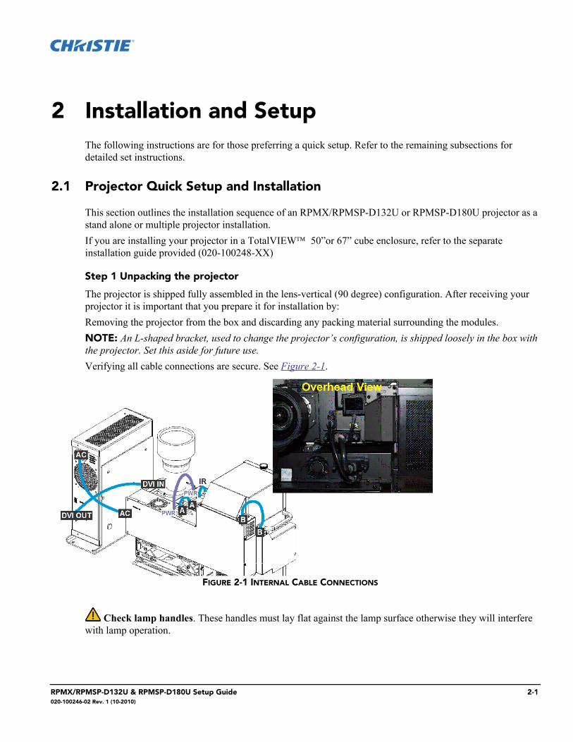
The projector is shipped fully assembled in the lens-vertical (90 degree) configuration. After receiving your projector it is important that you prepare it for installation by:Removing the projector from the box and discarding any packing material surrounding the modules. NOTE: An L-shaped bracket, used to change the projector’s configuration, is shipped loosely in the box with the projector. Set this aside for future use.Verifying all cable connections are secure. See Figure 2-1.
Check lamp handles. These handles must lay flat against the lamp surface otherwise they will interfere with lamp operation.
FIGURE 2-1 INTERNAL CABLE CONNECTIONS
RPMX/RPMSP-D132U & RPMSP-D180U Setup Guide 2-1020-100246-02 Rev. 1 (10-2010)
Section 2: Installation and Setup
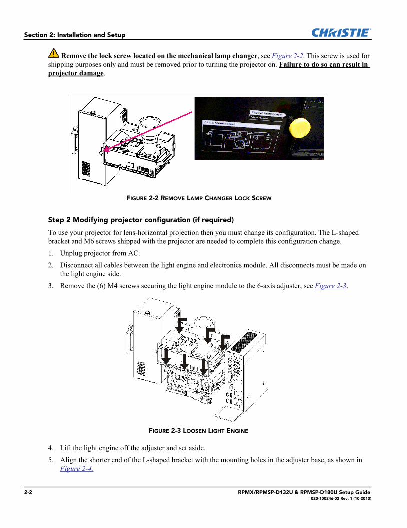
Remove the lock screw located on the mechanical lamp changer, see Figure 2-2. This screw is used for shipping purposes only and must be removed prior to turning the projector on. Failure to do so can result in projector damage.
Step 2 Modifying projector configuration (if required)
To use your projector for lens-horizontal projection then you must change its configuration. The L-shaped bracket and M6 screws shipped with the projector are needed to complete this configuration change.1. Unplug projector from AC.2. Disconnect all cables between the light engine and electronics module. All disconnects must be made on
the light engine side.3. Remove the (6) M4 screws securing the light engine module to the 6-axis adjuster, see Figure 2-3.
4. Lift the light engine off the adjuster and set aside.5. Align the shorter end of the L-shaped bracket with the mounting holes in the adjuster base, as shown in
Figure 2-4.
FIGURE 2-2 REMOVE LAMP CHANGER LOCK SCREW
FIGURE 2-3 LOOSEN LIGHT ENGINE
2-2 RPMX/RPMSP-D132U & RPMSP-D180U Setup Guide020-100246-02 Rev. 1 (10-2010)
Section 2: Installation and Setup
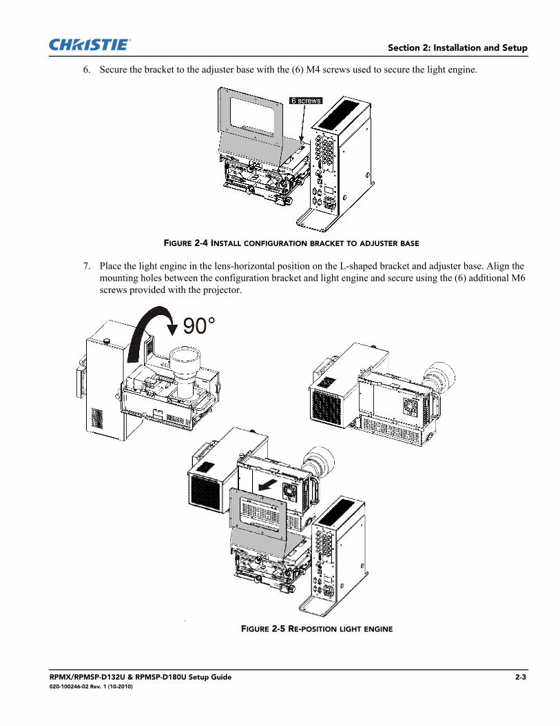
6. Secure the bracket to the adjuster base with the (6) M4 screws used to secure the light engine.
7. Place the light engine in the lens-horizontal position on the L-shaped bracket and adjuster base. Align the mounting holes between the configuration bracket and light engine and secure using the (6) additional M6 screws provided with the projector.
FIGURE 2-4 INSTALL CONFIGURATION BRACKET TO ADJUSTER BASE
FIGURE 2-5 RE-POSITION LIGHT ENGINE
RPMX/RPMSP-D132U & RPMSP-D180U Setup Guide 2-3020-100246-02 Rev. 1 (10-2010)
Section 2: Installation and Setup
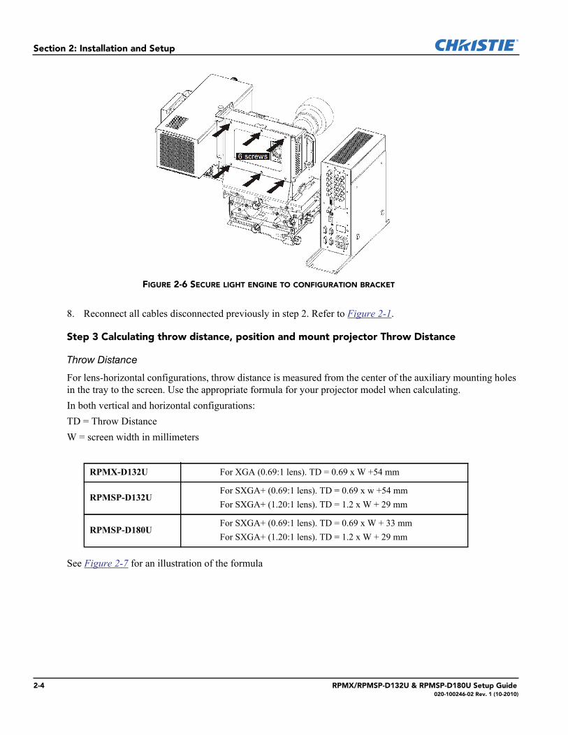
8. Reconnect all cables disconnected previously in step 2. Refer to Figure 2-1.
Step 3 Calculating throw distance, position and mount projector Throw Distance
Throw Distance
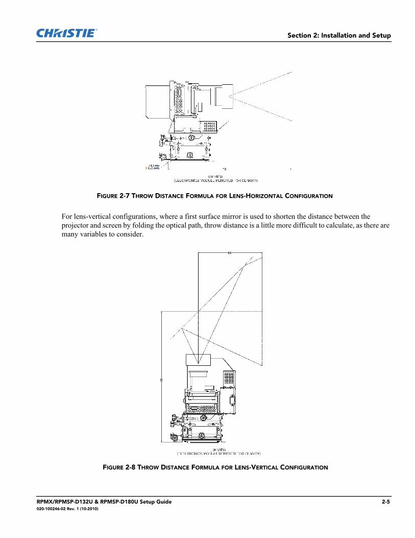
For lens-horizontal configurations, throw distance is measured from the center of the auxiliary mounting holes in the tray to the screen. Use the appropriate formula for your projector model when calculating. In both vertical and horizontal configurations:TD = Throw DistanceW = screen width in millimeters
See Figure 2-7 for an illustration of the formula
RPMX-D132U For XGA (0.69:1 lens). TD = 0.69 x W +54 mm
RPMSP-D132UFor SXGA+ (0.69:1 lens). TD = 0.69 x w +54 mmFor SXGA+ (1.20:1 lens). TD = 1.2 x W + 29 mm
RPMSP-D180UFor SXGA+ (0.69:1 lens). TD = 0.69 x W + 33 mmFor SXGA+ (1.20:1 lens). TD = 1.2 x W + 29 mm
FIGURE 2-6 SECURE LIGHT ENGINE TO CONFIGURATION BRACKET
2-4 RPMX/RPMSP-D132U & RPMSP-D180U Setup Guide020-100246-02 Rev. 1 (10-2010)
Section 2: Installation and Setup
For lens-vertical configurations, where a first surface mirror is used to shorten the distance between the projector and screen by folding the optical path, throw distance is a little more difficult to calculate, as there are many variables to consider.
FIGURE 2-7 THROW DISTANCE FORMULA FOR LENS-HORIZONTAL CONFIGURATION
FIGURE 2-8 THROW DISTANCE FORMULA FOR LENS-VERTICAL CONFIGURATION
RPMX/RPMSP-D132U & RPMSP-D180U Setup Guide 2-5020-100246-02 Rev. 1 (10-2010)
Section 2: Installation and Setup
Lifting and transporting the projector
It is recommended that you ask for someone’s help to lift the projector and use a stable cart to transport the projector.
Mounting
Refer to the drawings provided for your specific projector model in Appendix B Dimensions & Mounting Information of the user manual for mounting hole locations and other technical information.
Mount the projector to a sturdy, flat surface that fits the entire projector.
Use all four mounting points to secure the projector to the surface. Refer to Appendix B Dimensions &Mounting Information of the user manual.Maintain an area of empty space around the projector, called a “stay out zone”, to allow for aircirculation and clearance for cable connections to the input panel. An insufficient stay out zone area cancause the projector to overheat during operation and/or place undue stress on source connections.
Step 4 Connecting sources
All source connections are made to the input panel of the Electronics Module. Each input is labeled for easy identification. Using the appropriate cables, connect your source. Refer to 2.2 Connecting Sources for more details on connecting a specific source.NOTE: An optional input module can be installed at Input 5 if additional connections are required. Refer to Appendix D Optional Input Modules of the user manual.
Step 5 Turning the projector ON and selecting a source
A North American rated line cord is provided with this projector. For all other regions,make sure that you are using a line cord, power plug and socket that meet the applicable ratingstandards
1. Plug an approved line cord into the projector’s AC receptacle, located on the electronics module. Plug the 3-pronged end of the line cord into a grounded AC outlet.
NOTE: The outlet must be near the equipment and easily accessible. Use only the line cord provided with the projector or a power cord of appropriate ratings that comply with regional standards. NOTE: Do not use a line cord or AC supply not in the specified voltage and power range. Refer to Section 6 Specifications for projector power requirements of the user manual.
2. Press for two seconds to turn the projector ON. As the projector begins initialization, an active pattern of segments appears in the LED status display window. Commands will be ignored until “On” appears.
3. Press one of the input keys on the remote to select and display the image for the source connected in Step 4.
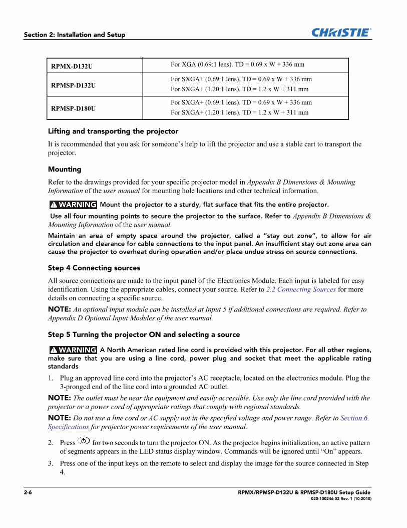
RPMX-D132U For XGA (0.69:1 lens). TD = 0.69 x W + 336 mm
RPMSP-D132UFor SXGA+ (0.69:1 lens). TD = 0.69 x W + 336 mmFor SXGA+ (1.20:1 lens). TD = 1.2 x W + 311 mm
RPMSP-D180UFor SXGA+ (0.69:1 lens). TD = 0.69 x W + 336 mmFor SXGA+ (1.20:1 lens). TD = 1.2 x W + 311 mm
2-6 RPMX/RPMSP-D132U & RPMSP-D180U Setup Guide020-100246-02 Rev. 1 (10-2010)
Section 2: Installation and Setup
NOTE: For more information on the keys available on the remote and their function, refer to Section 3 Operation.NOTE: The projector enforces a 60 second wait period from the time the projector is powered down and back up again.
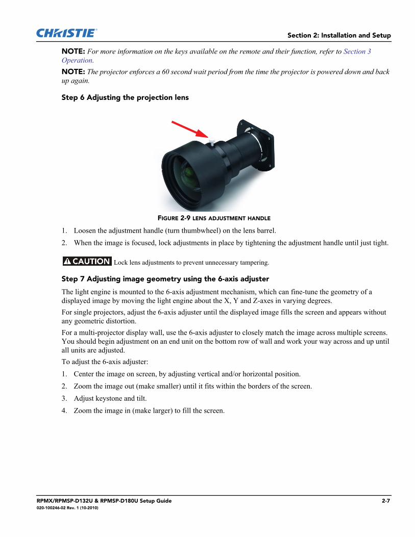
Step 6 Adjusting the projection lens
FIGURE 2-9 LENS ADJUSTMENT HANDLE
1. Loosen the adjustment handle (turn thumbwheel) on the lens barrel.2. When the image is focused, lock adjustments in place by tightening the adjustment handle until just tight.
Lock lens adjustments to prevent unnecessary tampering.
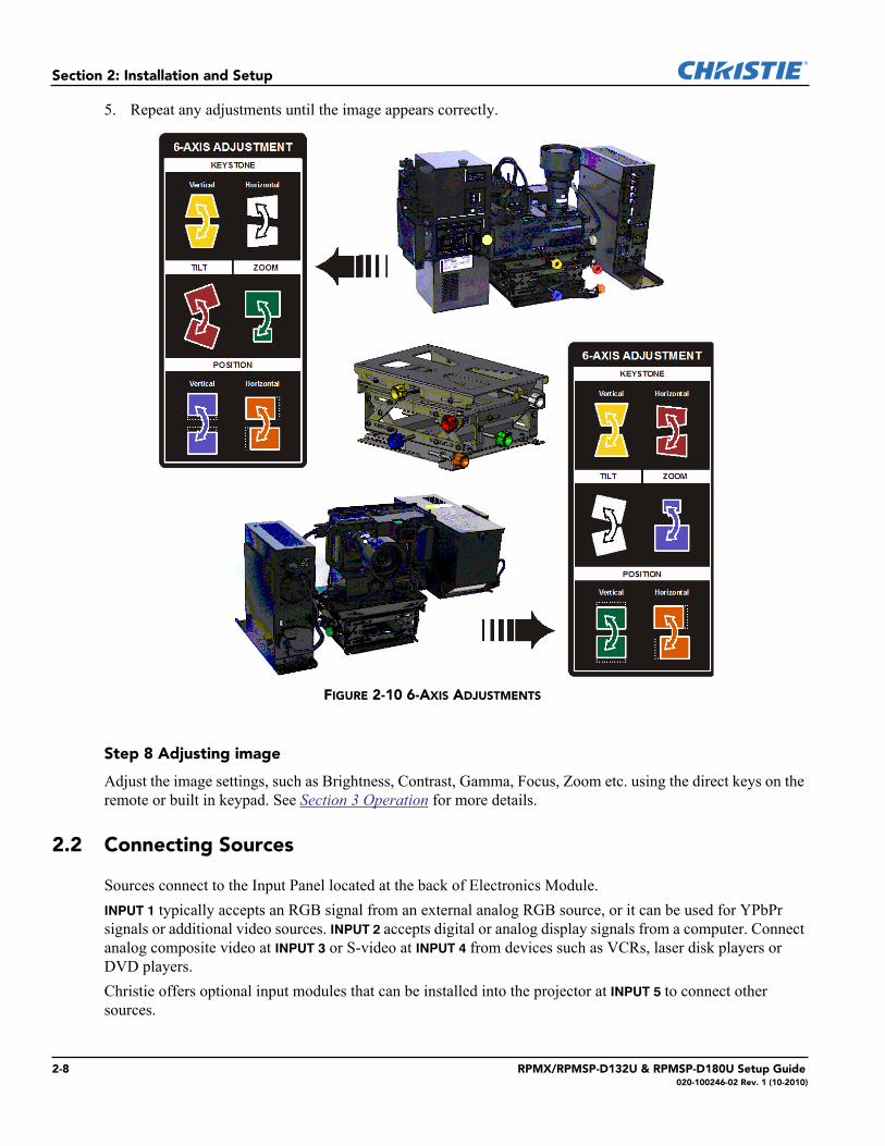
Step 7 Adjusting image geometry using the 6-axis adjuster
The light engine is mounted to the 6-axis adjustment mechanism, which can fine-tune the geometry of a displayed image by moving the light engine about the X, Y and Z-axes in varying degrees. For single projectors, adjust the 6-axis adjuster until the displayed image fills the screen and appears without any geometric distortion.For a multi-projector display wall, use the 6-axis adjuster to closely match the image across multiple screens. You should begin adjustment on an end unit on the bottom row of wall and work your way across and up until all units are adjusted.To adjust the 6-axis adjuster:1. Center the image on screen, by adjusting vertical and/or horizontal position.2. Zoom the image out (make smaller) until it fits within the borders of the screen.3. Adjust keystone and tilt.4. Zoom the image in (make larger) to fill the screen.
RPMX/RPMSP-D132U & RPMSP-D180U Setup Guide 2-7020-100246-02 Rev. 1 (10-2010)
Section 2: Installation and Setup
5. Repeat any adjustments until the image appears correctly.
Step 8 Adjusting image
Adjust the image settings, such as Brightness, Contrast, Gamma, Focus, Zoom etc. using the direct keys on the remote or built in keypad. See Section 3 Operation for more details.
2.2 Connecting Sources
Sources connect to the Input Panel located at the back of Electronics Module. INPUT 1 typically accepts an RGB signal from an external analog RGB source, or it can be used for YPbPr signals or additional video sources. INPUT 2 accepts digital or analog display signals from a computer. Connect analog composite video at INPUT 3 or S-video at INPUT 4 from devices such as VCRs, laser disk players or DVD players. Christie offers optional input modules that can be installed into the projector at INPUT 5 to connect other sources.
FIGURE 2-10 6-AXIS ADJUSTMENTS
2-8 RPMX/RPMSP-D132U & RPMSP-D180U Setup Guide020-100246-02 Rev. 1 (10-2010)
Section 2: Installation and Setup
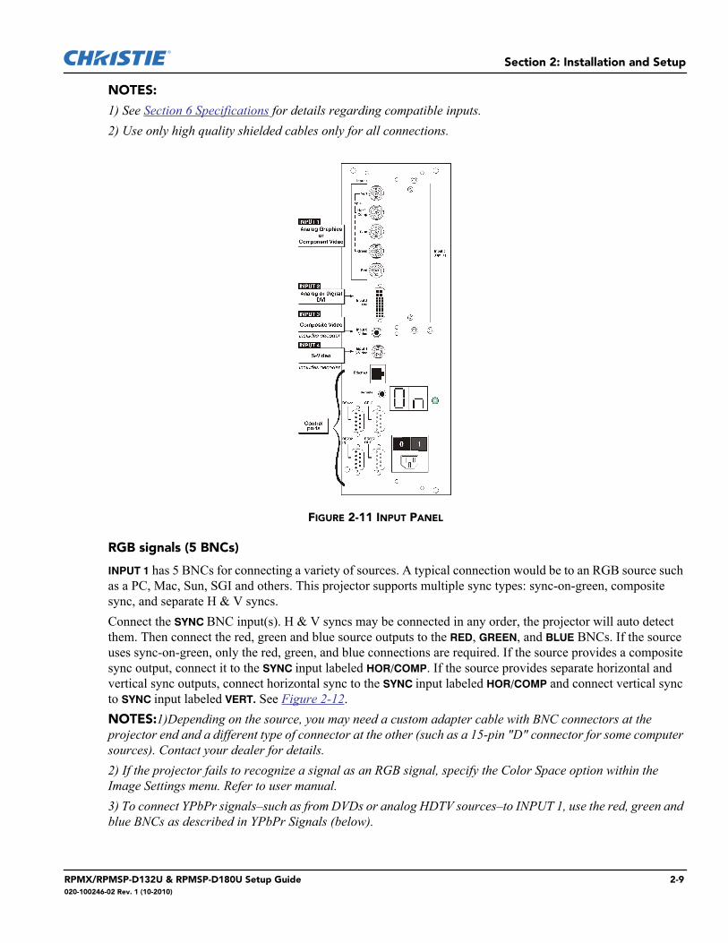
NOTES:
1) See Section 6 Specifications for details regarding compatible inputs.2) Use only high quality shielded cables only for all connections.
FIGURE 2-11 INPUT PANEL
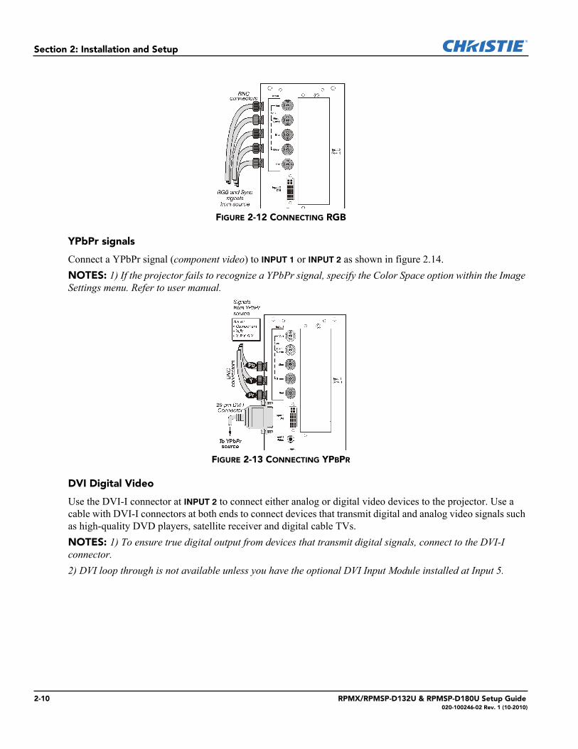
RGB signals (5 BNCs)
INPUT 1 has 5 BNCs for connecting a variety of sources. A typical connection would be to an RGB source such as a PC, Mac, Sun, SGI and others. This projector supports multiple sync types: sync-on-green, composite sync, and separate H & V syncs.Connect the SYNC BNC input(s). H & V syncs may be connected in any order, the projector will auto detect them. Then connect the red, green and blue source outputs to the RED, GREEN, and BLUE BNCs. If the source uses sync-on-green, only the red, green, and blue connections are required. If the source provides a composite sync output, connect it to the SYNC input labeled HOR/COMP. If the source provides separate horizontal and vertical sync outputs, connect horizontal sync to the SYNC input labeled HOR/COMP and connect vertical sync to SYNC input labeled VERT. See Figure 2-12.NOTES:1)Depending on the source, you may need a custom adapter cable with BNC connectors at the projector end and a different type of connector at the other (such as a 15-pin "D" connector for some computer sources). Contact your dealer for details. 2) If the projector fails to recognize a signal as an RGB signal, specify the Color Space option within the Image Settings menu. Refer to user manual.3) To connect YPbPr signals–such as from DVDs or analog HDTV sources–to INPUT 1, use the red, green and blue BNCs as described in YPbPr Signals (below).
RPMX/RPMSP-D132U & RPMSP-D180U Setup Guide 2-9020-100246-02 Rev. 1 (10-2010)
Section 2: Installation and Setup
FIGURE 2-12 CONNECTING RGB
YPbPr signals
Connect a YPbPr signal (component video) to INPUT 1 or INPUT 2 as shown in figure 2.14.NOTES: 1) If the projector fails to recognize a YPbPr signal, specify the Color Space option within the Image Settings menu. Refer to user manual.
FIGURE 2-13 CONNECTING YPBPR
DVI Digital Video
Use the DVI-I connector at INPUT 2 to connect either analog or digital video devices to the projector. Use a cable with DVI-I connectors at both ends to connect devices that transmit digital and analog video signals such as high-quality DVD players, satellite receiver and digital cable TVs.NOTES: 1) To ensure true digital output from devices that transmit digital signals, connect to the DVI-I connector.2) DVI loop through is not available unless you have the optional DVI Input Module installed at Input 5.
2-10 RPMX/RPMSP-D132U & RPMSP-D180U Setup Guide020-100246-02 Rev. 1 (10-2010)
Section 2: Installation and Setup
FIGURE 2-14 CONNECTING ANALOG OR DIGITAL VIDEO DEVICES
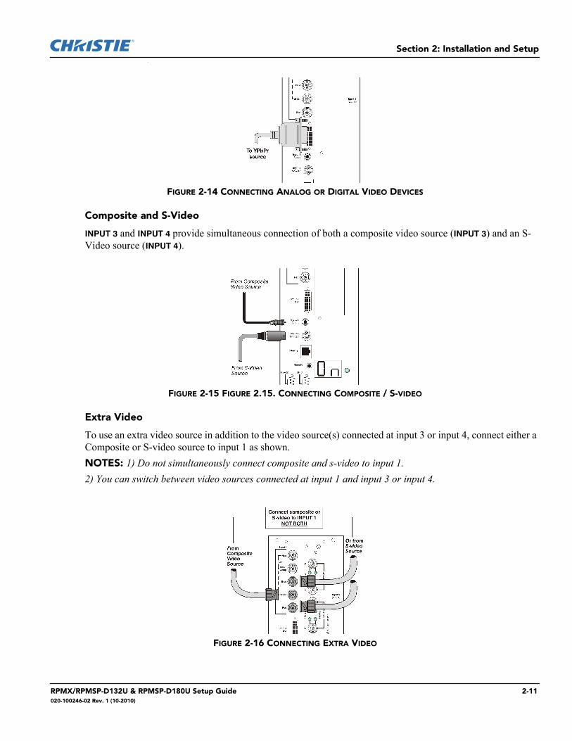
Composite and S-Video
INPUT 3 and INPUT 4 provide simultaneous connection of both a composite video source (INPUT 3) and an S-Video source (INPUT 4).
FIGURE 2-15 FIGURE 2.15. CONNECTING COMPOSITE / S-VIDEO
Extra Video
To use an extra video source in addition to the video source(s) connected at input 3 or input 4, connect either a Composite or S-video source to input 1 as shown.NOTES: 1) Do not simultaneously connect composite and s-video to input 1. 2) You can switch between video sources connected at input 1 and input 3 or input 4.
FIGURE 2-16 CONNECTING EXTRA VIDEO
RPMX/RPMSP-D132U & RPMSP-D180U Setup Guide 2-11020-100246-02 Rev. 1 (10-2010)
Section 2: Installation and Setup
Optional Inputs
Optional input modules allow you to increase your total number of inputs to accommodate different signal types, whether analog or digital. Install in the area labeled INPUT 5. Options include:• RGB 500 Input Module• RGB 400 Active Loop Thru Input Module• RGB 400 Buffered Amplifier Input Module• PC250 Analog Input Module• Serial Digital Input Module• DVI Input Module• Dual SD/HD-SDI Module NOTE: Refer to the user manual for a brief description of each interface.
2.3 Connecting Communications
As an alternative to the projector’s keypad or remote, communicate with the projector using a PC or other controller. Commands and feedback are sent via serial links (RS-232 and RS-422) and Ethernet or GPIO communications to the projector.
2.3.1 Remote Keypad
Direct the projector’s IR remote keypad towards the display screen or the projector’s IR sensor. Alternatively, connect a wired (tethered) version of the remote to the RCA jack labeled REMOTE on the projector’s input panel. Response to a wired keypad must be enabled in the Communications menu—see 3.6, Adjusting System Parameters and Advanced Controls for more information.
2.3.2 Serial Port Connections
RS-232 and RS-422 are the serial ports available on the projector. Connect a device with a serial interface, such as a computer to either of these connectors (not both) and control the projector remotely by entering specific serial communication commands.
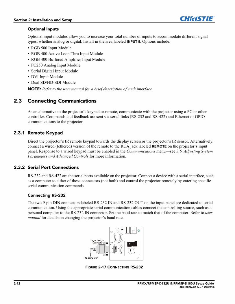
Connecting RS-232
The two 9-pin DIN connectors labeled RS-232 IN and RS-232 OUT on the input panel are dedicated to serial communication. Using the appropriate serial communication cables connect the controlling source, such as a personal computer to the RS-232 IN connector. Set the baud rate to match that of the computer. Refer to user manual for details on changing the projector’s baud rate.
FIGURE 2-17 CONNECTING RS-232
2-12 RPMX/RPMSP-D132U & RPMSP-D180U Setup Guide020-100246-02 Rev. 1 (10-2010)
Section 2: Installation and Setup
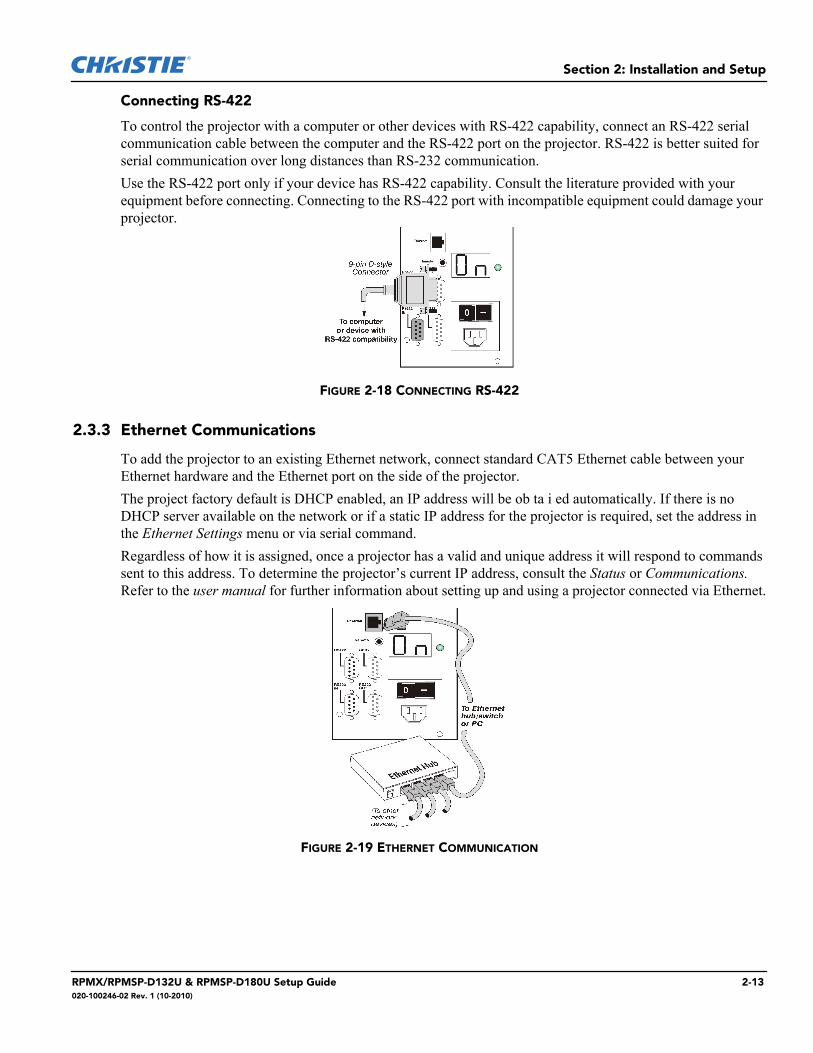
Connecting RS-422
To control the projector with a computer or other devices with RS-422 capability, connect an RS-422 serial communication cable between the computer and the RS-422 port on the projector. RS-422 is better suited for serial communication over long distances than RS-232 communication. Use the RS-422 port only if your device has RS-422 capability. Consult the literature provided with your equipment before connecting. Connecting to the RS-422 port with incompatible equipment could damage your projector.
FIGURE 2-18 CONNECTING RS-422
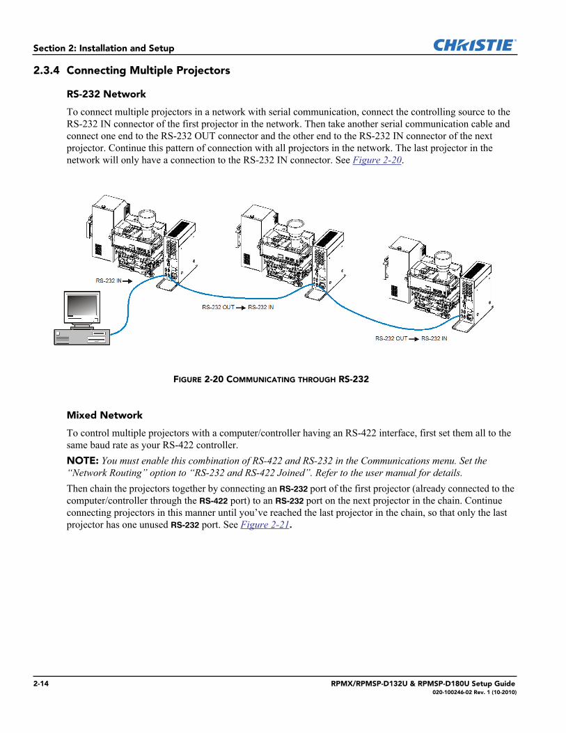
2.3.3 Ethernet Communications
To add the projector to an existing Ethernet network, connect standard CAT5 Ethernet cable between your Ethernet hardware and the Ethernet port on the side of the projector.The project factory default is DHCP enabled, an IP address will be ob ta i ed automatically. If there is no DHCP server available on the network or if a static IP address for the projector is required, set the address in the Ethernet Settings menu or via serial command.Regardless of how it is assigned, once a projector has a valid and unique address it will respond to commands sent to this address. To determine the projector’s current IP address, consult the Status or Communications. Refer to the user manual for further information about setting up and using a projector connected via Ethernet.
FIGURE 2-19 ETHERNET COMMUNICATION
RPMX/RPMSP-D132U & RPMSP-D180U Setup Guide 2-13020-100246-02 Rev. 1 (10-2010)
Section 2: Installation and Setup
2.3.4 Connecting Multiple Projectors
RS-232 Network
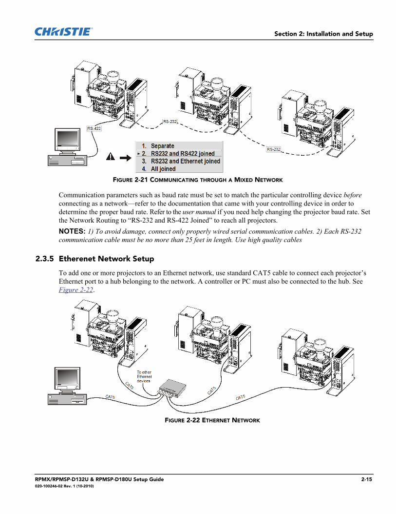
To connect multiple projectors in a network with serial communication, connect the controlling source to the RS-232 IN connector of the first projector in the network. Then take another serial communication cable and connect one end to the RS-232 OUT connector and the other end to the RS-232 IN connector of the next projector. Continue this pattern of connection with all projectors in the network. The last projector in the network will only have a connection to the RS-232 IN connector. See Figure 2-20.
Mixed Network
To control multiple projectors with a computer/controller having an RS-422 interface, first set them all to the same baud rate as your RS-422 controller.NOTE: You must enable this combination of RS-422 and RS-232 in the Communications menu. Set the “Network Routing” option to “RS-232 and RS-422 Joined”. Refer to the user manual for details.Then chain the projectors together by connecting an RS-232 port of the first projector (already connected to the computer/controller through the RS-422 port) to an RS-232 port on the next projector in the chain. Continue connecting projectors in this manner until you’ve reached the last projector in the chain, so that only the last projector has one unused RS-232 port. See Figure 2-21.
FIGURE 2-20 COMMUNICATING THROUGH RS-232
2-14 RPMX/RPMSP-D132U & RPMSP-D180U Setup Guide020-100246-02 Rev. 1 (10-2010)
Section 2: Installation and Setup
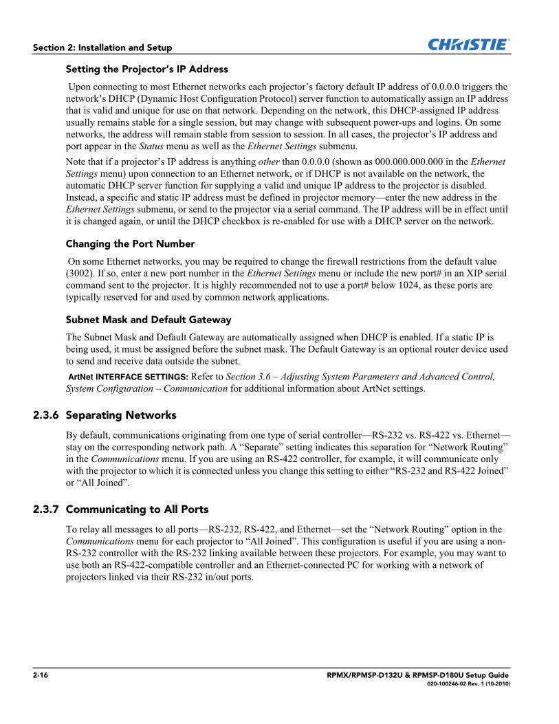
Communication parameters such as baud rate must be set to match the particular controlling device before connecting as a network—refer to the documentation that came with your controlling device in order to determine the proper baud rate. Refer to the user manual if you need help changing the projector baud rate. Set the Network Routing to “RS-232 and RS-422 Joined” to reach all projectors.NOTES: 1) To avoid damage, connect only properly wired serial communication cables. 2) Each RS-232 communication cable must be no more than 25 feet in length. Use high quality cables
2.3.5 Etherenet Network Setup
To add one or more projectors to an Ethernet network, use standard CAT5 cable to connect each projector’s Ethernet port to a hub belonging to the network. A controller or PC must also be connected to the hub. See Figure 2-22.
FIGURE 2-21 COMMUNICATING THROUGH A MIXED NETWORK
FIGURE 2-22 ETHERNET NETWORK
RPMX/RPMSP-D132U & RPMSP-D180U Setup Guide 2-15020-100246-02 Rev. 1 (10-2010)
Section 2: Installation and Setup
Setting the Projector’s IP Address
Upon connecting to most Ethernet networks each projector’s factory default IP address of 0.0.0.0 triggers the network’s DHCP (Dynamic Host Configuration Protocol) server function to automatically assign an IP address that is valid and unique for use on that network. Depending on the network, this DHCP-assigned IP address usually remains stable for a single session, but may change with subsequent power-ups and logins. On some networks, the address will remain stable from session to session. In all cases, the projector’s IP address and port appear in the Status menu as well as the Ethernet Settings submenu. Note that if a projector’s IP address is anything other than 0.0.0.0 (shown as 000.000.000.000 in the Ethernet Settings menu) upon connection to an Ethernet network, or if DHCP is not available on the network, the automatic DHCP server function for supplying a valid and unique IP address to the projector is disabled. Instead, a specific and static IP address must be defined in projector memory—enter the new address in the Ethernet Settings submenu, or send to the projector via a serial command. The IP address will be in effect until it is changed again, or until the DHCP checkbox is re-enabled for use with a DHCP server on the network.
Changing the Port Number
On some Ethernet networks, you may be required to change the firewall restrictions from the default value (3002). If so, enter a new port number in the Ethernet Settings menu or include the new port# in an XIP serial command sent to the projector. It is highly recommended not to use a port# below 1024, as these ports are typically reserved for and used by common network applications.
Subnet Mask and Default Gateway
The Subnet Mask and Default Gateway are automatically assigned when DHCP is enabled. If a static IP is being used, it must be assigned before the subnet mask. The Default Gateway is an optional router device used to send and receive data outside the subnet. ArtNet INTERFACE SETTINGS: Refer to Section 3.6 – Adjusting System Parameters and Advanced Control, System Configuration – Communication for additional information about ArtNet settings.
2.3.6 Separating Networks
By default, communications originating from one type of serial controller—RS-232 vs. RS-422 vs. Ethernet—stay on the corresponding network path. A “Separate” setting indicates this separation for “Network Routing” in the Communications menu. If you are using an RS-422 controller, for example, it will communicate only with the projector to which it is connected unless you change this setting to either “RS-232 and RS-422 Joined” or “All Joined”.
2.3.7 Communicating to All Ports
To relay all messages to all ports—RS-232, RS-422, and Ethernet—set the “Network Routing” option in the Communications menu for each projector to “All Joined”. This configuration is useful if you are using a non-RS-232 controller with the RS-232 linking available between these projectors. For example, you may want to use both an RS-422-compatible controller and an Ethernet-connected PC for working with a network of projectors linked via their RS-232 in/out ports.
2-16 RPMX/RPMSP-D132U & RPMSP-D180U Setup Guide020-100246-02 Rev. 1 (10-2010)
Section 2: Installation and Setup
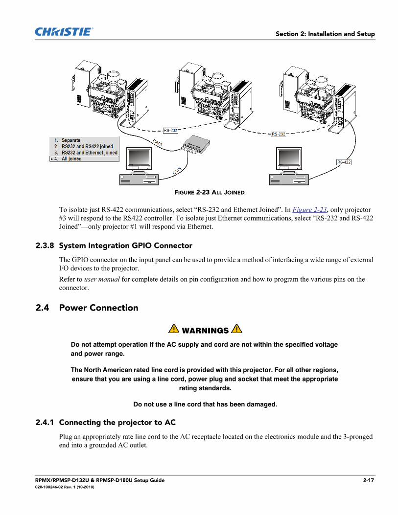
To isolate just RS-422 communications, select “RS-232 and Ethernet Joined”. In Figure 2-23, only projector #3 will respond to the RS422 controller. To isolate just Ethernet communications, select “RS-232 and RS-422 Joined”—only projector #1 will respond via Ethernet.
2.3.8 System Integration GPIO Connector
The GPIO connector on the input panel can be used to provide a method of interfacing a wide range of external I/O devices to the projector. Refer to user manual for complete details on pin configuration and how to program the various pins on the connector.
2.4 Power Connection
WARNINGS
Do not attempt operation if the AC supply and cord are not within the specified voltage and power range.
The North American rated line cord is provided with this projector. For all other regions, ensure that you are using a line cord, power plug and socket that meet the appropriate
rating standards.
Do not use a line cord that has been damaged.
2.4.1 Connecting the projector to AC
Plug an appropriately rate line cord to the AC receptacle located on the electronics module and the 3-pronged end into a grounded AC outlet.
FIGURE 2-23 ALL JOINED
RPMX/RPMSP-D132U & RPMSP-D180U Setup Guide 2-17020-100246-02 Rev. 1 (10-2010)

Section 2: Installation and Setup
NOTE: The outlet must be near the equipment and easily accessible. Use only the line cord provided with the projector or a power cord of appropriate ratings that comply with regional standards. The input voltage to the projector must be capable of 100-240 VAC.
2.4.2 Disconnecting the projector from AC
Power down the projector and wait for the internal cooling fans to stop before turning the main power switch on the electronics module OFF. This gives the lamps enough time to cool. At that time, unplug the line cord from the wall outlet.Refer to Section 6 Specifications for complete details on all power requirements for the projector.
WARNINGS
Wait for the cooling fans to stop before turning the main power switch OFF and unplugging the projector.
2-18 RPMX/RPMSP-D132U & RPMSP-D180U Setup Guide020-100246-02 Rev. 1 (10-2010)
3 OperationThis section explains how to operate the projector once it has been setup and installed. Read this section and familiarize yourself with the components and menu options before using your projector.
3.1 Using Remote IR Keypad
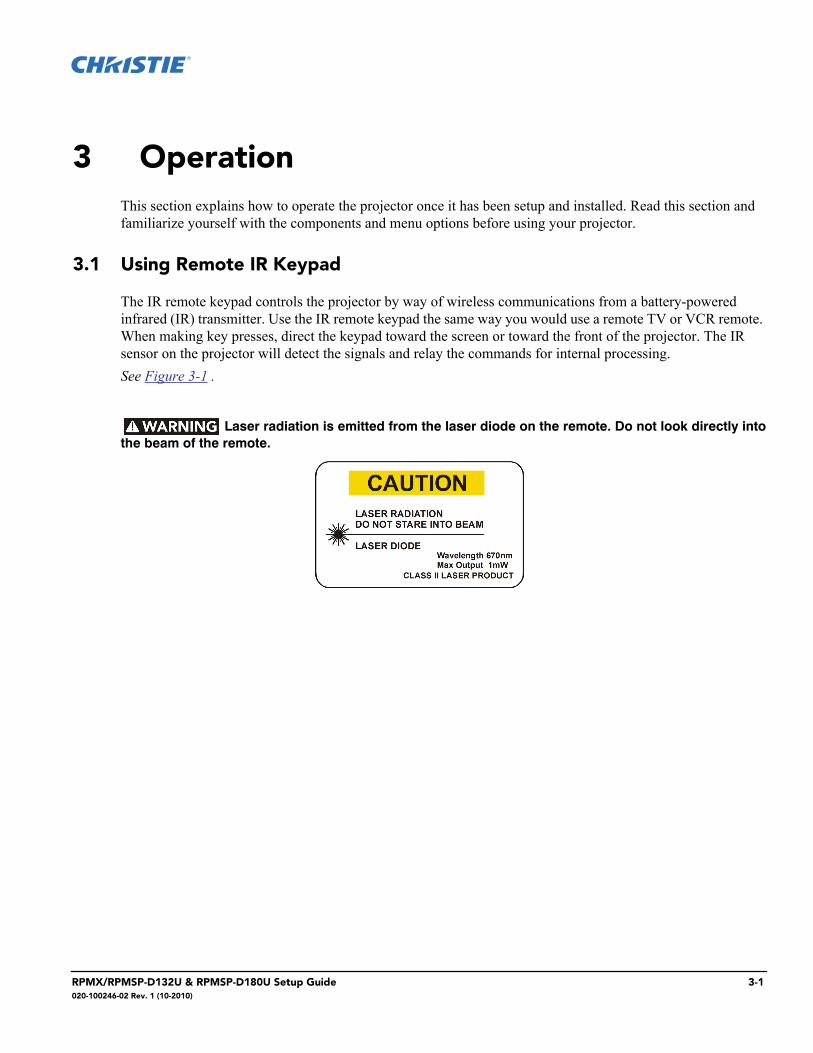
The IR remote keypad controls the projector by way of wireless communications from a battery-powered infrared (IR) transmitter. Use the IR remote keypad the same way you would use a remote TV or VCR remote. When making key presses, direct the keypad toward the screen or toward the front of the projector. The IR sensor on the projector will detect the signals and relay the commands for internal processing.See Figure 3-1 .
Laser radiation is emitted from the laser diode on the remote. Do not look directly intothe beam of the remote.
RPMX/RPMSP-D132U & RPMSP-D180U Setup Guide 3-1020-100246-02 Rev. 1 (10-2010)
Section 3: Operation
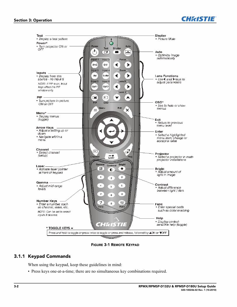
FIGURE 3-1 REMOTE KEYPAD
3.1.1 Keypad Commands
When using the keypad, keep these guidelines in mind:• Press keys one-at-a-time; there are no simultaneous key combinations required.
3-2 RPMX/RPMSP-D132U & RPMSP-D180U Setup Guide020-100246-02 Rev. 1 (10-2010)
Section 3: Operation
• Power and OSD keys —are “press-and-hold” keys that do not function with a typical quick press-and-release key press.
• Hold arrow keys down for continuous adjustment/movement in one direction. In serial networks, pause briefly between adjustments to ensure that more distant projectors can “keep up” with the commands.
• If you press a key while the projector is still responding to the previous action, such as during power-up, the second key press may not take effect.
Specific keypad commands are:
Power ON/OFF
There are 3 options to power the projector ON or OFF:
• Press for two seconds to toggle the projector ON/OFF state.
• Press followed immediately by (ON) or (OFF) to switch the projector ON or OFF.
• Press to toggle the present ON/OFF state.NOTES:
1) After powering down, the lamp cooling fan remains on for approximately 1-2 minutes to cool the lamp. 2) Keep the projector OFF for a few minutes. Hot re-strikes of the lamp may reduce lamp life. 3) The projector enforces a 60 second wait between powering OFF and ON to allow the lamp to cool down. You will see vertical scrolling bars across the status display during this wait period
Test
Steps through the internal test patterns and the current input.
Press and then the and arrow keys to cycle in either direction through the test patterns.
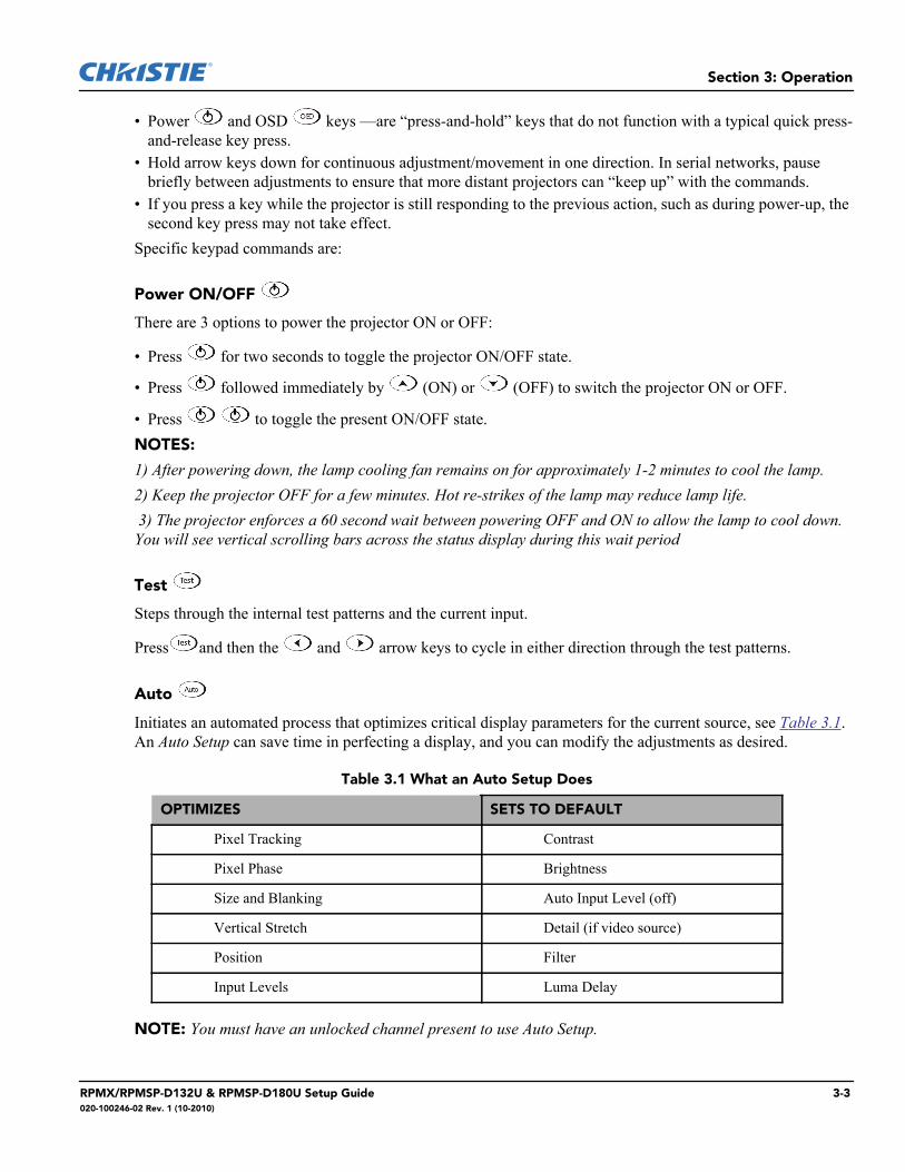
Auto
Initiates an automated process that optimizes critical display parameters for the current source, see Table 3.1. An Auto Setup can save time in perfecting a display, and you can modify the adjustments as desired.
Table 3.1 What an Auto Setup Does
NOTE: You must have an unlocked channel present to use Auto Setup.
OPTIMIZES SETS TO DEFAULT
Pixel Tracking Contrast
Pixel Phase Brightness
Size and Blanking Auto Input Level (off)
Vertical Stretch Detail (if video source)
Position Filter
Input Levels Luma Delay
RPMX/RPMSP-D132U & RPMSP-D180U Setup Guide 3-3020-100246-02 Rev. 1 (10-2010)
Section 3: Operation
Channel
Select a source setup (channel) defined and stored in projector memory. Enter a 2-digit channel number, the display will automatically update according to the setup parameters defined for that channel. A new channel is automatically created if you adjust an image from a new sourceNOTE: To display a list of available channels for selection make sure the Display Channel List option is enabled in the Menu Preferences menu. See Menu Preferences later in this section.
Input 1
Displays from the data or video input source connected to BNCs labeled INPUT 1.
Input 2
Displays from the DVI source connected to INPUT 2.
Input 3
Displays from the composite video source connected to INPUT 3.
Input 4
Displays from the S-video source connected to INPUT 4.
Input 5
Displays from the INPUT 5 interface module installed in the Option 1 slot. NOTE: If you have the new optional Dual SD/HD-SDI Module installed at input 5 you can connect two inputs
– A and B. Whether you are displaying from input 5 or from another input, press to display the input last
used. Press again to toggle to the other input.
Input 6
Not applicable.
Contrast
Changes the amount of white in your images. Use keys until you reach the desired level of contrast—for best results, start low and increase so that whites remain bright but are not distorted or tinted, and that light areas do not become white (“crushed”). Conversely, low contrast causes dim images.
Brightness
Increases or decreases the amount of black in the image. Use keys until you reach the desired level of contrast. For best results, start high and decrease so that dark areas do not become black (“crushed”). Conversely, overly high brightness changes black to dark gray, causing washed-out images.
3-4 RPMX/RPMSP-D132U & RPMSP-D180U Setup Guide020-100246-02 Rev. 1 (10-2010)
Section 3: Operation
Gamma
“Gamma” determines how gray shades are displayed between minimum input (black) and maximum input (white) for a given amount of signal. The proper setting (normal gamma setting is 2.22) helps maintain optimized blacks and whites while ensuring a smooth transition for the “in-between” values utilized in grays. The overall tone of an image can be lightened or darkened without changing the two extremes, and your images will be more vibrant yet with good detail in dark areas.If excess ambient light washes out the image and it becomes difficult to see details in dark areas, lower the gamma setting to compensate.
Menu
Press to enter or exit the projector’s menu system.
OSD (On-screen display)
Press followed by to hide the projector’s menu system during use. Invisible menus are fully functional, enabling “hidden” access to numbered features and image adjustments by entering the correspond-ing sequence of key presses on the keypad. To see the menus again, do one of the following:
• Press and hold for a second
• Press and release followed immediately by
• Press NOTE: With OSD “on”, you can still hide error messages and slidebars by disabling these options in the Menu Preferences menu.
PIP (Picture in Picture)
Press to enable and disable Picture-in-Picture. PIP enables you to display two different images simultaneously – typically a smaller “secondary” image within a large “primary” background. When a menu control or
slidebar is present, press to toggle the current function to affect the other image.NOTE: Disable PIP and Best Switching for Interlaced sources > 35 kHz.
Function Key
IF WITHIN A MENU: Using the for special tasks within the menu system is
noted with the appropriate topic elsewhere in Section 3. For example, press in the Channel Setup menu to enable deletion or copying of a channel.
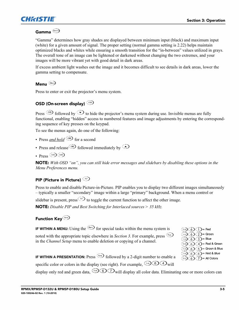
IF WITHIN A PRESENTATION: Press followed by a 2-digit number to enable a
specific color or colors in the display (see right). For example, will
display only red and green data, will display all color data. Eliminating one or more colors can
RPMX/RPMSP-D132U & RPMSP-D180U Setup Guide 3-5020-100246-02 Rev. 1 (10-2010)
Section 3: Operation
help with certain diagnostics and setups, such as when accurately overlaying one image on top of another from stacked projectors.NOTE: Color enabling can also be implemented from numerous locations within the menu system.
Shutter
Picture mute toggle. Picture mute replaces video with a black screen.
Projector
Used to access a specific projector within a group of projectors or to confirm if the local projector is listening. The number in the “Enter Number” window indicates which projector is currently listening to commands, and will match the projector number that is defined in the Menu Preferences menu.A checkmark indicates that the projector is connected to a keypad and is listening to commands from that keypad. If there is no checkmark, you are communicating with a different projector.To control a specific projector with the keypad, enter the projector’s 3-digit number. If you switch to another projector, the checkmark will disappear. When broadcasting to multiple projectors, press the button twice without entering a projector number. Keypad commands will then affect all projectors present. There is no method of controlling a group of projectors within the same wired configuration using the wired keypad exclusivelyNOTE: The “Broadcast Keys” option in the Communications menu must be selected for only one (any) projector in a serial network. The keypad in use must be OFF (disabled) for the remaining projectors. See also 3.6, Adjusting System Parameters and Advanced Controls.
Enter
Press to select a highlighted item, to toggle a checkbox, or to accept a parameter adjustment and return to the previous menu or image.
Exit
Press to return to the previous level, such as the previous menu.
NOTE: does not save changes within text editing boxes (including number editing of a slidebar value) or within pull-down lists. It acts as a “cancel” in these cases.
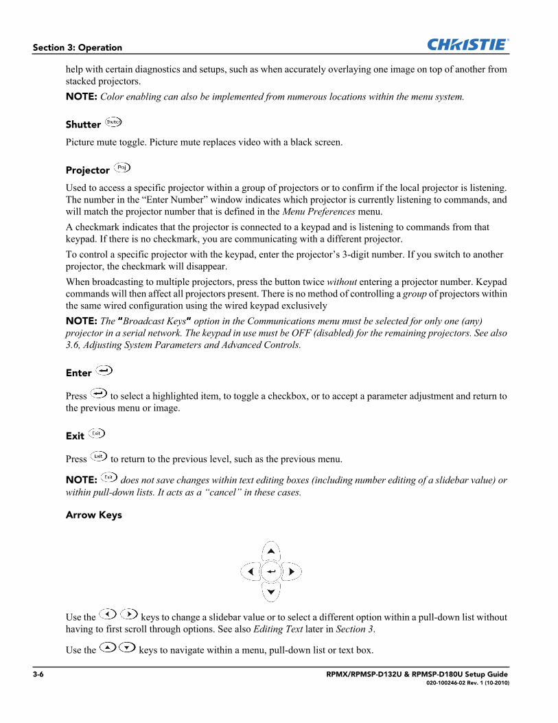
Arrow Keys
Use the keys to change a slidebar value or to select a different option within a pull-down list without having to first scroll through options. See also Editing Text later in Section 3.
Use the keys to navigate within a menu, pull-down list or text box.
3-6 RPMX/RPMSP-D132U & RPMSP-D180U Setup Guide020-100246-02 Rev. 1 (10-2010)
Section 3: Operation
Lens Focus, Zoom and Lens H, Lens V
NOTE: Not applicable.
Laser
Activates the laser pointer on the remote. Keep the key depressed and point the remote at the screen to highlight an area of the presentation. Release it to turn it off. The closer you are to the screen the brighter the laser beam appears. The laser pointer works best in an environment where ambient lighting can be controlled.
NOTE: The batteries must be in the remote keypad for the key to work.
3.2 Navigating the Menus
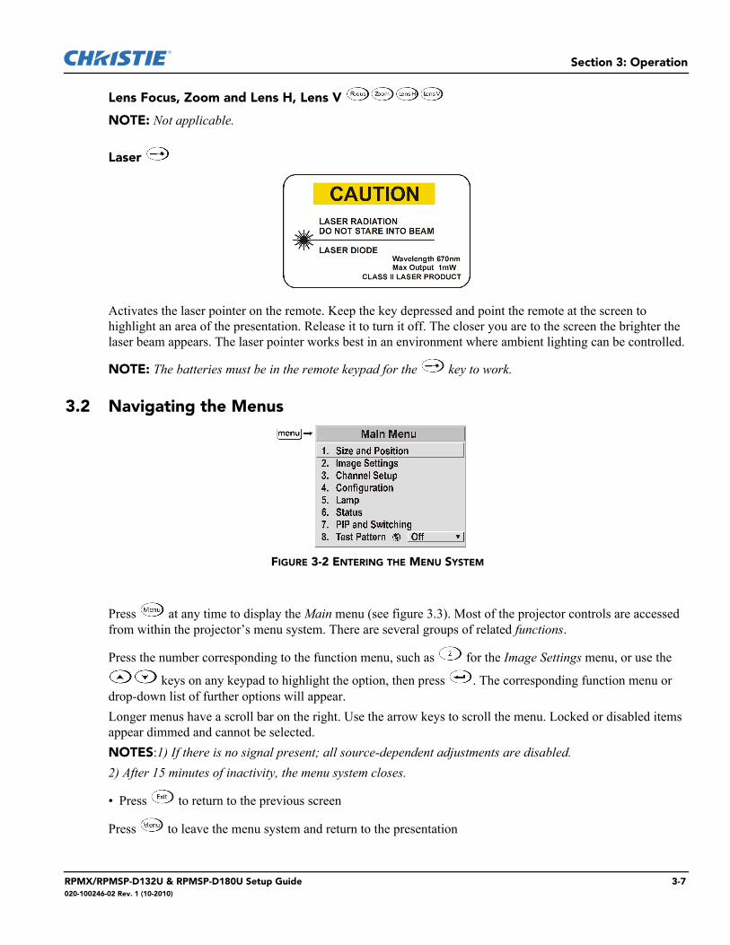
Press at any time to display the Main menu (see figure 3.3). Most of the projector controls are accessed from within the projector’s menu system. There are several groups of related functions.
Press the number corresponding to the function menu, such as for the Image Settings menu, or use the
keys on any keypad to highlight the option, then press . The corresponding function menu or drop-down list of further options will appear.Longer menus have a scroll bar on the right. Use the arrow keys to scroll the menu. Locked or disabled items appear dimmed and cannot be selected.NOTES:1) If there is no signal present; all source-dependent adjustments are disabled. 2) After 15 minutes of inactivity, the menu system closes.
• Press to return to the previous screen
Press to leave the menu system and return to the presentation
FIGURE 3-2 ENTERING THE MENU SYSTEM
RPMX/RPMSP-D132U & RPMSP-D180U Setup Guide 3-7020-100246-02 Rev. 1 (10-2010)
Section 3: Operation
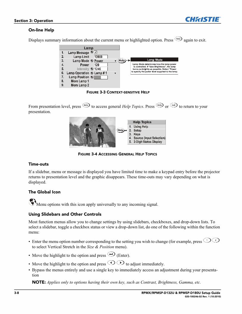
On-line Help
Displays summary information about the current menu or highlighted option. Press again to exit.
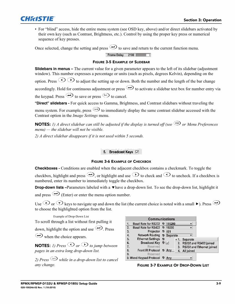
From presentation level, press to access general Help Topics. Press or to return to your presentation.
FIGURE 3-4 ACCESSING GENERAL HELP TOPICS
Time-outs
If a slidebar, menu or message is displayed you have limited time to make a keypad entry before the projector returns to presentation level and the graphic disappears. These time-outs may vary depending on what is displayed.
The Global Icon
Menu options with this icon apply universally to any incoming signal.
Using Slidebars and Other Controls
Most function menus allow you to change settings by using slidebars, checkboxes, and drop-down lists. To select a slidebar, toggle a checkbox status or view a drop-down list, do one of the following within the function menu:
• Enter the menu option number corresponding to the setting you wish to change (for example, press to select Vertical Stretch in the Size & Position menu).
• Move the highlight to the option and press (Enter).
• Move the highlight to the option and press to adjust immediately.• Bypass the menus entirely and use a single key to immediately access an adjustment during your presenta-
tionNOTE: Applies only to options having their own key, such as Contrast, Brightness, Gamma, etc.
FIGURE 3-3 CONTEXT-SENSITIVE HELP
3-8 RPMX/RPMSP-D132U & RPMSP-D180U Setup Guide020-100246-02 Rev. 1 (10-2010)
Section 3: Operation
• For “blind” access, hide the entire menu system (see OSD key, above) and/or direct slidebars activated by their own key (such as Contrast, Brightness, etc.). Control by using the proper key press or numerical sequence of key presses.
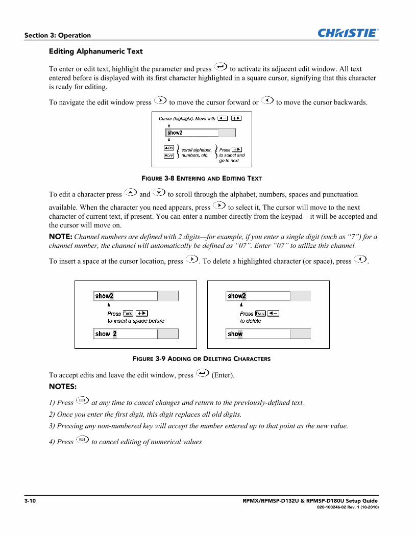
Once selected, change the setting and press to save and return to the current function menu.
FIGURE 3-5 EXAMPLE OF SLIDEBAR
Slidebars in menus – The current value for a given parameter appears to the left of its slidebar (adjustment window). This number expresses a percentage or units (such as pixels, degrees Kelvin), depending on the
option. Press to adjust the setting up or down. Both the number and the length of the bar change
accordingly. Hold for continuous adjustment or press to activate a slidebar text box for number entry via
the keypad. Press to save or press to cancel.“Direct” slidebars - For quick access to Gamma, Brightness, and Contrast slidebars without traveling the
menu system. For example, press to immediately display the same contrast slidebar accessed with the Contrast option in the Image Settings menu.
NOTES: 1) A direct slidebar can still be adjusted if the display is turned off (see or Menu Preferences menu) — the slidebar will not be visible. 2) A direct slidebar disappears if it is not used within 5 seconds.
FIGURE 3-6 EXAMPLE OF CHECKBOX
Checkboxes - Conditions are enabled when the adjacent checkbox contains a checkmark. To toggle the
checkbox, highlight and press , or highlight and use to check and to uncheck. If a checkbox is numbered, enter its number to immediately toggle the checkbox.Drop-down lists –Parameters labeled with a have a drop-down list. To see the drop-down list, highlight it
and press (Enter) or enter the menu option number.
Use or keys to navigate up and down the list (the current choice is noted with a small ). Press to choose the highlighted option from the list.
Example of Drop-Down List
To scroll through a list without first pulling it
down, highlight the option and use . Press
when the choice appears.
NOTES: 1) Press or to jump between pages in an extra long drop-down list.
2) Press while in a drop-down list to cancel any change. FIGURE 3-7 EXAMPLE OF DROP-DOWN LIST
RPMX/RPMSP-D132U & RPMSP-D180U Setup Guide 3-9020-100246-02 Rev. 1 (10-2010)
Section 3: Operation
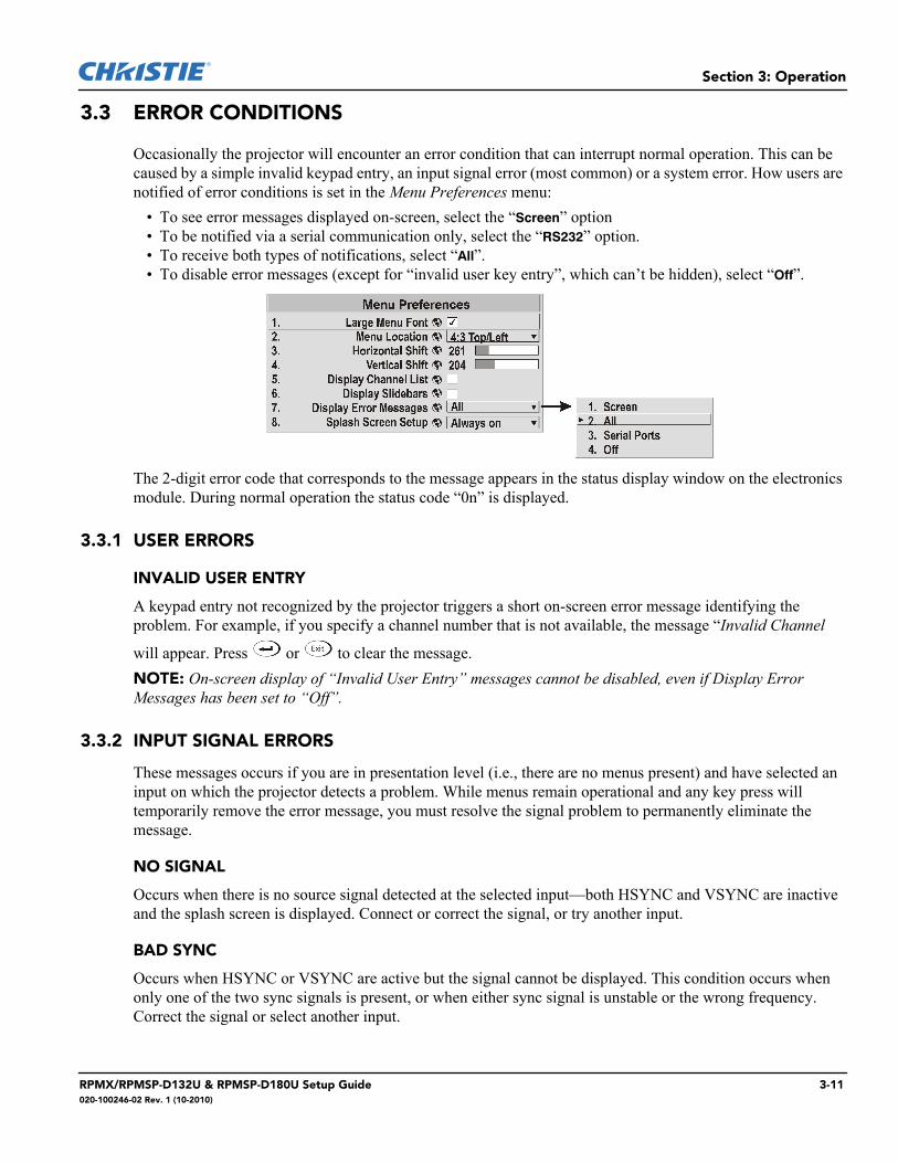
Editing Alphanumeric Text
To enter or edit text, highlight the parameter and press to activate its adjacent edit window. All text entered before is displayed with its first character highlighted in a square cursor, signifying that this character is ready for editing.
To navigate the edit window press to move the cursor forward or to move the cursor backwards.
FIGURE 3-8 ENTERING AND EDITING TEXT
To edit a character press and to scroll through the alphabet, numbers, spaces and punctuation
available. When the character you need appears, press to select it, The cursor will move to the next character of current text, if present. You can enter a number directly from the keypad—it will be accepted and the cursor will move on.NOTE: Channel numbers are defined with 2 digits—for example, if you enter a single digit (such as “7”) for a channel number, the channel will automatically be defined as “07”. Enter “07” to utilize this channel.
To insert a space at the cursor location, press . To delete a highlighted character (or space), press .
FIGURE 3-9 ADDING OR DELETING CHARACTERS
To accept edits and leave the edit window, press (Enter). NOTES:
1) Press at any time to cancel changes and return to the previously-defined text.2) Once you enter the first digit, this digit replaces all old digits.3) Pressing any non-numbered key will accept the number entered up to that point as the new value.
4) Press to cancel editing of numerical values
3-10 RPMX/RPMSP-D132U & RPMSP-D180U Setup Guide020-100246-02 Rev. 1 (10-2010)
Section 3: Operation
3.3 ERROR CONDITIONS
Occasionally the projector will encounter an error condition that can interrupt normal operation. This can be caused by a simple invalid keypad entry, an input signal error (most common) or a system error. How users are notified of error conditions is set in the Menu Preferences menu:
• To see error messages displayed on-screen, select the “Screen” option• To be notified via a serial communication only, select the “RS232” option.• To receive both types of notifications, select “All”. • To disable error messages (except for “invalid user key entry”, which can’t be hidden), select “Off”.
The 2-digit error code that corresponds to the message appears in the status display window on the electronics module. During normal operation the status code “0n” is displayed.
3.3.1 USER ERRORS
INVALID USER ENTRY
A keypad entry not recognized by the projector triggers a short on-screen error message identifying the problem. For example, if you specify a channel number that is not available, the message “Invalid Channel
will appear. Press or to clear the message.NOTE: On-screen display of “Invalid User Entry” messages cannot be disabled, even if Display Error Messages has been set to “Off”.
3.3.2 INPUT SIGNAL ERRORS
These messages occurs if you are in presentation level (i.e., there are no menus present) and have selected an input on which the projector detects a problem. While menus remain operational and any key press will temporarily remove the error message, you must resolve the signal problem to permanently eliminate the message.
NO SIGNAL
Occurs when there is no source signal detected at the selected input—both HSYNC and VSYNC are inactive and the splash screen is displayed. Connect or correct the signal, or try another input.
BAD SYNC
Occurs when HSYNC or VSYNC are active but the signal cannot be displayed. This condition occurs when only one of the two sync signals is present, or when either sync signal is unstable or the wrong frequency. Correct the signal or select another input.
RPMX/RPMSP-D132U & RPMSP-D180U Setup Guide 3-11020-100246-02 Rev. 1 (10-2010)
Section 3: Operation
OTHER SIGNAL ERROR MESSAGES
You may encounter a signal error message indicating that HSYNC and/or VSYNC are either too fast or too slow. When this message appears, check the frequencies shown in the Status menu. If they are correct, then the signal is not recognized by the projector. On some PCs you may be able to change the settings to generate a compatible signal. If the frequencies shown in the Status menu are incorrect, check the cabling to see where the problem might originate. Encrypted signal message error indicates that it does not have HDCP but that an HDCP signal is plugged in.
3.3.3 SYSTEM WARNINGS / ERRORS
When the projector encounters a system malfunction, a System Warning or a System Error message will appear. These messages are accompanied by a numerical error code shown in the status display window. A system
malfunction can be cleared with from presentation level, but may indicate the need for service by a qualified service technician. For best results reset the projector—power the projector down and up with the
(power) key. Wait at least 90 seconds and allow for proper cooling.
NOTE: System messages appear on-screen only if Display Error Messages has been set to “Screen” or “All”.
SYSTEM WARNINGS
Indicates that a system malfunction exists. A system warning message replaces any input signal message and disappears when the input signal status changes. While the projector will remain operational, the message indicates a potentially serious problem that should be reported to the manufacturer. Reset the projector.
SYSTEM ERRORS
Indicates that a serious malfunction exists and must be reported to the manufacturer as soon as possible. The projector will no longer operate. Reset the projector.
3.3.4 STATUS DISPLAY
Located just above the main power switch is a two-digit status display window that displays the current status of the projector. If the projector encounters an error during operation, an error code number will display. During normal operation “On” appears in the window.
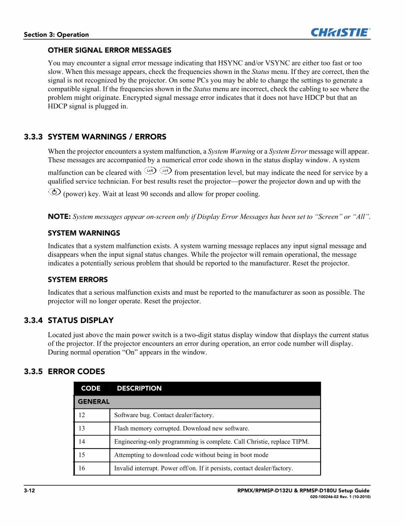
3.3.5 ERROR CODES
qCODE qDESCRIPTION
GENERAL
12 Software bug. Contact dealer/factory.
13 Flash memory corrupted. Download new software.
14 Engineering-only programming is complete. Call Christie, replace TIPM.
15 Attempting to download code without being in boot mode
16 Invalid interrupt. Power off/on. If it persists, contact dealer/factory.
3-12 RPMX/RPMSP-D132U & RPMSP-D180U Setup Guide020-100246-02 Rev. 1 (10-2010)
Section 3: Operation
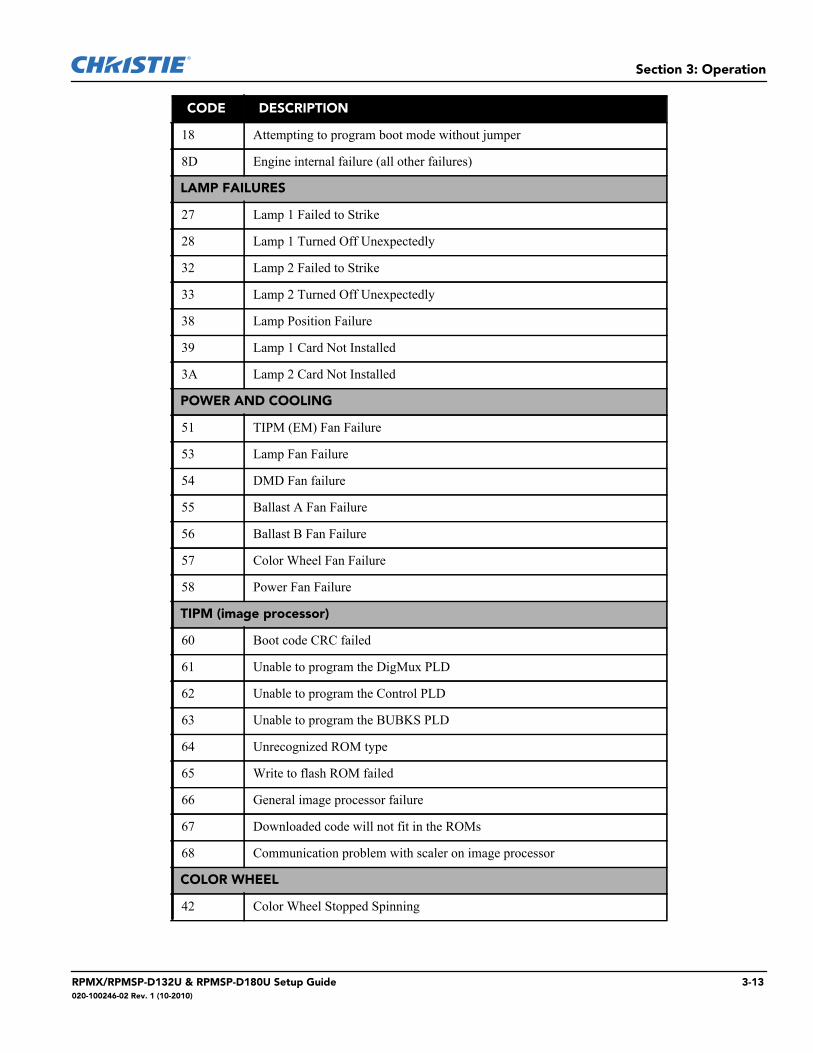
18 Attempting to program boot mode without jumper
8D Engine internal failure (all other failures)
LAMP FAILURES
27 Lamp 1 Failed to Strike
28 Lamp 1 Turned Off Unexpectedly
32 Lamp 2 Failed to Strike
33 Lamp 2 Turned Off Unexpectedly
38 Lamp Position Failure
39 Lamp 1 Card Not Installed
3A Lamp 2 Card Not Installed
POWER AND COOLING
51 TIPM (EM) Fan Failure
53 Lamp Fan Failure
54 DMD Fan failure
55 Ballast A Fan Failure
56 Ballast B Fan Failure
57 Color Wheel Fan Failure
58 Power Fan Failure
TIPM (image processor)
60 Boot code CRC failed
61 Unable to program the DigMux PLD
62 Unable to program the Control PLD
63 Unable to program the BUBKS PLD
64 Unrecognized ROM type
65 Write to flash ROM failed
66 General image processor failure
67 Downloaded code will not fit in the ROMs
68 Communication problem with scaler on image processor
COLOR WHEEL
42 Color Wheel Stopped Spinning
qCODE qDESCRIPTION
RPMX/RPMSP-D132U & RPMSP-D180U Setup Guide 3-13020-100246-02 Rev. 1 (10-2010)
Section 3: Operation
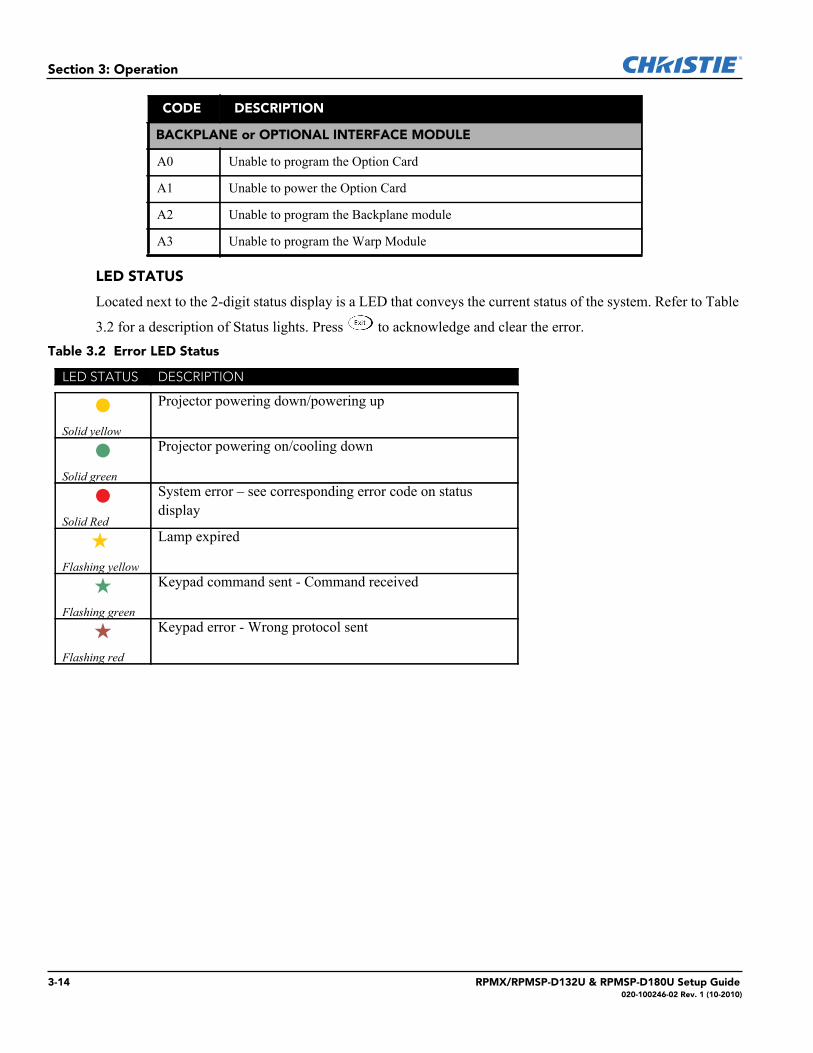
LED STATUS
Located next to the 2-digit status display is a LED that conveys the current status of the system. Refer to Table
3.2 for a description of Status lights. Press to acknowledge and clear the error. Table 3.2 Error LED Status
BACKPLANE or OPTIONAL INTERFACE MODULE
A0 Unable to program the Option Card
A1 Unable to power the Option Card
A2 Unable to program the Backplane module
A3 Unable to program the Warp Module
LED STATUS DESCRIPTION
Solid yellow
Projector powering down/powering up
Solid green
Projector powering on/cooling down
Solid Red
System error – see corresponding error code on status display
Flashing yellow
Lamp expired
Flashing green
Keypad command sent - Command received
Flashing red
Keypad error - Wrong protocol sent
qCODE qDESCRIPTION
3-14 RPMX/RPMSP-D132U & RPMSP-D180U Setup Guide020-100246-02 Rev. 1 (10-2010)
4 Maintenance
4.1 Projector Location
Operate the projector in an environment, which meets the operating range as specified in Section 6 – Specifica-tions.
• Do not operate the projector close to water, such as near a swimming pool. Do not operate in extremely humid environments.
• Do not place the projector on an unstable cart, stand or table. A projector and cart combination should be used with care. Sudden stops, excessive force and uneven surfaces may cause the projector and cart com-bination to overturn.
• Do not ceiling mount this projector.
4.2 Ventilation
Slots and vents in the projector provide ventilation to ensure reliable operation and prevent overheating. Do not block or cover these openings. • Do not place the projector over a radiator or heat register. • Do not place the projector in an enclosure without proper ventilation.• Do not “poke” objects into the ventilation openings of the projector. They may touch dangerous voltages or
short-out components resulting in a fire or shock hazard. • Do not spill liquids into the projector. If a spill occurs, immediately unplug the projector and have it serviced
by a qualified service technician.
4.3 Servicing
Do not attempt to service the projector yourself. All servicing must be performed byCHRISTIE accredited service technicians.
Use replacement parts that are manufacturer-approved only. Use of any other part other than the onesspecified by the manufacturer can result in fire, electric shock or risk of personal injury and irreparableequipment damage.
Never service the projector while it is still plugged in. There are exposed voltages that could cause severe physical injuries and possibly death. Always unplug the projector and wait 2 minutes to allow the capacitors on the power supply to discharge before removing the projector’s covers.
If any of these conditions exist, immediately unplug the projector from the power outlet and ask a qualified service technician to look at it.• The power cord is damaged.• The internal cooling fans do not turn on when the projector is first powered up. • Liquid is spilled into the projector.• The projector is exposed to excessive moisture.
RPMX/RPMSP-D132U & RPMSP-D180U Setup Guide 4-1020-100246-02 Rev. 1 (10-2010)
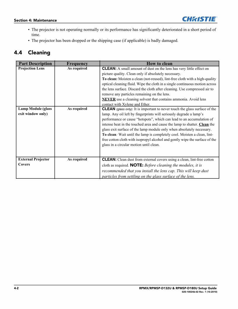
Section 4: Maintenance
• The projector is not operating normally or its performance has significantly deteriorated in a short period of time.
• The projector has been dropped or the shipping case (if applicable) is badly damaged.
4.4 Cleaning
Part Description Frequency How to cleanProjection Lens As required CLEAN: A small amount of dust on the lens has very little effect on
picture quality. Clean only if absolutely necessary.To clean: Moisten a clean (not-reused), lint-free cloth with a high-quality optical cleaning fluid. Wipe the cloth in a single continuous motion across the lens surface. Discard the cloth after cleaning. Use compressed air to remove any particles remaining on the lens.NEVER use a cleaning solvent that contains ammonia. Avoid lens contact with Xylene and Ether.
Lamp Module (glass exit window only)
As required CLEAN (glass only): It is important to never touch the glass surface of the lamp. Any oil left by fingerprints will seriously degrade a lamp’s performance or cause “hotspots”, which can lead to an accumulation of intense heat in the touched area and cause the lamp to shatter. Clean the glass exit surface of the lamp module only when absolutely necessary.To clean: Wait until the lamp is completely cool. Moisten a clean, lint-free cotton cloth with isopropyl alcohol and gently wipe the surface of the glass in a circular motion until clean.
External Projector Covers
As required CLEAN: Clean dust from external covers using a clean, lint-free cotton cloth as required. NOTE: Before cleaning the modules, it is recommended that you install the lens cap. This will keep dust particles from settling on the glass surface of the lens.
4-2 RPMX/RPMSP-D132U & RPMSP-D180U Setup Guide020-100246-02 Rev. 1 (10-2010)
5 TroubleshootingIf the projector is not operating properly, note the symptoms and use this guide to assist you. If you cannot resolve the problems yourself, contact your dealer for assistance.NOTE: A qualified service technician is required when opening the projector to diagnose any “probable cause”.
5.1 Displays
5.1.1 The projector is on but there is no display
1. Was a lens cover accidentally left on? Remove lens cover.2. Is the lamp ignited? It could take up to 5 attempts to strike a lamp. With a 30 second wait period in
between each attempt it could take a total of 2 minutes to turn the lamp on. Check LAMP STATUS. 3. NOTE: After striking the lamp, it can take up to 5 minutes to achieve full brightness.4. Is the correct input selected?5. Is the source connected properly? Check the cable connections and ensure the correct source is selected.
6. Can you access test patterns? Ensure there is not a full black test pattern selected for display—press
to access test patterns, then cycle patterns with keys.
7. Check EM and PHM connection.
5.1.2 Severe motion artifacts
There is a synchronization problem with reversed 3/2 pull-down in 60Hz-to-24Hz film-to-digital conversion in your source. Correct at the source.
5.1.3 The display is jittery or unstable
1. Ensure that the source is properly connected and of adequate quality for detection. With a poor quality or improperly connected source, the projector will repeatedly attempt to display an image, however briefly.
2. The horizontal or vertical scan frequency of the input signal may be out of range for the projector. Refer to Section 6, Specifications for scan frequency ranges.
3. The sync signal may be inadequate. Correct the source problem.
5.1.4 The display is faint
1. Brightness and/or contrast may be set very low.2. The source may be double terminated. Ensure the source is terminated only once.3. The source (if non-video) may need a different sync tip clamp location.4. Adjust LAMP POSITION to optimize the position of the lamp for maximum brightness.
RPMX/RPMSP-D132U & RPMSP-D180U Setup Guide 5-1020-100246-02 Rev. 1 (10-2010)
Section 5: Troubleshooting
5.1.5 The upper portion of the display is waving, tearing or jittering
This can sometimes occur with video or VCR sources. Check your source.
5.1.6 Portions of the display are cut off or wrap to the opposite edge
Resizing and/or blanking may need adjustment.
5.1.7 The display appears compressed (vertically stretched)
1. The frequency of the pixel sampling clock is incorrect for the current source.2. Resizing, vertical stretch and positioning options may be improperly adjusted for the incoming source
signal.
5.1.8 Data is cropped from edges
1. Check settings for Blanking.2. If incoming data is still missing from the image, reduce the image size to within the display area available
in the projector.
5.1.9 Display quality appears to drift from good to bad, bad to good
1. The source input signal may be of low quality.2. The H or V frequency of the input may have changed at the source end.
5.1.10 The display has suddenly frozen
If the screen blacks out inexplicably, it is possible that excessive voltage noise on the AC or ground input has interrupted the projector’s ability to lock on to a signal. Power down the projector and disconnect from AC. Then plug in again and power up as usual.
5.1.11 Colors in the display are inaccurate
1. The color, tint, color space, color temperature and/or other settings may require adjustment.2. Ensure you are using the proper channel for this source.3. Check Color Wheel Calibration.
5.1.12 The display is not rectangular
1. Check leveling of the projector. Ensure that the lens surface and screen are as parallel to each other as possible.
2. Is the vertical offset correct? Adjust as necessary using the vertical offset knob.3. Check if Keystone is incorrectly set.
5-2 RPMX/RPMSP-D132U & RPMSP-D180U Setup Guide020-100246-02 Rev. 1 (10-2010)
Section 5: Troubleshooting
5.1.13 The display is “noisy”
1. Display adjustment at your input source may be required. Adjust pixel tracking, phase and filter. Noise is particularly common on YPbPr signals from a DVD player. (If using a PC source, adjust using a high-frequency test pattern with one pixel on/off throughout.)
2. The video input may not be terminated. Ensure the video input is terminated (75 ). If it is the last connection in a loop-through chain, the video input should be terminated at the last source input only.
3. The input signal and/or signal cables carrying the input signal may be of poor quality.4. If the distance between the input source device and the projector is greater than 25 feet, signal amplifica-
tion/conditioning may be required.5. If the source is a VCR or off-air broadcast, detail may be set too high.
5.1.14 Projector Delayed on Power Up
The projector enforces a 60 second delay between powering down and up again, because a hot lamp is more difficult to ignite. NOTE: It can take 2 minutes to cool a lamp sufficiently enough before re-striking it.
5.1.15 Powered Up, But No Light on the Wall
It takes approximately 60 seconds for the projector to power up and strike a lamp. A UHP lamp may not strike on the first attempt. In this case, the projector will wait 30 seconds before striking the lamp again. It will try a total of five times before it declares the lamp as “Failed to Strike”. Therefore it could take up to 2 minutes before light is seen on the wall. You can check the status of either lamp in the projector by checking LAMP STATUS in the Lamp Menu.
5.1.16 Projector is not powered
Verify that the DVI (Digital Video) and Power are connected to the Power Head Module (PHM). When there is no power to the PHM the lights will not function.
5.1.17 Incorrect Lamp Serial Number on Status Page
When replacing a lamp in a projector with a new lamp, remember to replace the lamp card (PCB). This card contains key information about your lamp, such as serial number, and factory default color primaries. If not installed, this can lead to incorrect lamp histories and difficulty with projector color matching.
5.2 Ethernet
1. Ensure the Ethernet settings are valid for your site—all network devices should have the same subnet mask and unique IP addresses.
2. Save any address change, and re-boot to implement.3. If you still have trouble establishing communications with a projector added to an existing Ethernet
network, the projector’s IP address is likely in conflict with another address already in use. Contact your network administrator.
RPMX/RPMSP-D132U & RPMSP-D180U Setup Guide 5-3020-100246-02 Rev. 1 (10-2010)

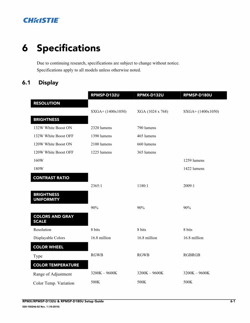
6 SpecificationsDue to continuing research, specifications are subject to change without notice. Specifications apply to all models unless otherwise noted.
6.1 Display
RPMSP-D132U RPMX-D132U RPMSP-D180U
RESOLUTION
SXGA+ (1400x1050) XGA (1024 x 768) SXGA+ (1400x1050)
BRIGHTNESS
132W White Boost ON 2320 lumens 790 lumens
132W White Boost OFF 1390 lumens 465 lumens
120W White Boost ON 2100 lumens 660 lumens
120W White Boost OFF 1225 lumens 365 lumens
160W 1259 lumens
180W 1422 lumens
CONTRAST RATIO
2365:1 1180:1 2009:1
BRIGHTNESS UNIFORMITY
90% 90% 90%
COLORS AND GRAY SCALE
Resolution 8 bits 8 bits 8 bits
Displayable Colors 16.8 million 16.8 million 16.8 million
COLOR WHEEL
Type RGWB RGWB RGBRGB
COLOR TEMPERATURE
Range of Adjustment 3200K – 9600K 3200K – 9600K 3200K – 9600K
Color Temp. Variation 500K 500K 500K
RPMX/RPMSP-D132U & RPMSP-D180U Setup Guide 6-1
020-100246-02 Rev. 1 (10-2010)
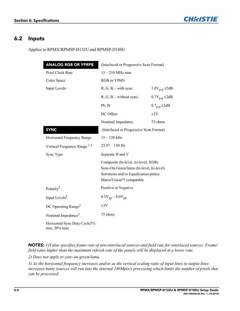
Section 6: Specifications
6.2 Inputs
Applies to RPMX/RPMSP-D132U and RPMSP-D180U
NOTES: 1)Value specifies frame rate of non-interlaced sources and field rate for interlaced sources. Frame/field rates higher than the maximum refresh rate of the panels will be displayed at a lower rate.2) Does not apply to sync-on-green/luma.3) As the horizontal frequency increases and/or as the vertical scaling ratio of input lines to output lines increases many sources will run into the internal 180Mpix/s processing which limits the number of pixels that can be processed.
ANALOG RGB OR YPRPB (Interlaced or Progressive Scan Format)
Pixel Clock Rate 13 – 210 MHz max
Color Space RGB or YPbPr
Input Levels: R, G, B, - with sync: 1.0Vp-p 2dB
R, G, B, - without sync: 0.7Vp-p 2dB
Pb, Pr 0.7p-p 2dB
DC Offset 2V
Nominal Impedance 75 ohms
SYNC (Interlaced or Progressive Scan Format)
Horizontal Frequency Range 15 – 120 kHz
Vertical Frequency Range 1,3 23.97 – 150 Hz
Sync Type Separate H and V
Composite (bi-level, tri-level, XOR)Sync-On-Green/luma (bi-level, tri-level)Serrations and/or Equalization pulsesMarcoVision compatible
Polarity2 Positive or Negative
Input Levels2 0.5Vpp – 4.0Vpp
DC Operating Range2 3V
Nominal Impedance2 75 ohms
Horizontal Sync Duty Cycle3% min, 20% max
6-2 RPMX/RPMSP-D132U & RPMSP-D180U Setup Guide020-100246-02 Rev. 1 (10-2010)
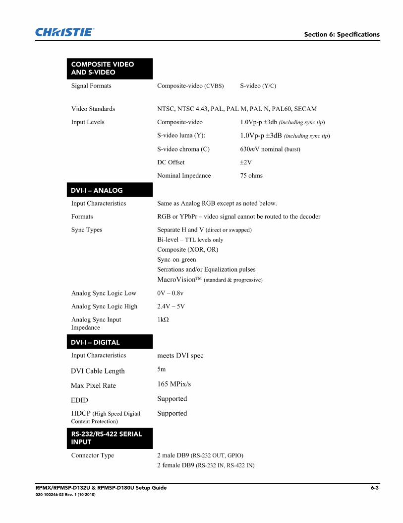
Section 6: Specifications
COMPOSITE VIDEO AND S-VIDEO
Signal Formats Composite-video (CVBS) S-video (Y/C)
Video Standards NTSC, NTSC 4.43, PAL, PAL M, PAL N, PAL60, SECAM
Input Levels Composite-video 1.0Vp-p 3db (including sync tip)
S-video luma (Y): 1.0Vp-p 3dB (including sync tip)
S-video chroma (C) 630mV nominal (burst)
DC Offset 2V
Nominal Impedance 75 ohms
DVI-I – ANALOG
Input Characteristics Same as Analog RGB except as noted below.
Formats RGB or YPbPr – video signal cannot be routed to the decoder
Sync Types Separate H and V (direct or swapped)
Bi-level – TTL levels only Composite (XOR, OR)Sync-on-greenSerrations and/or Equalization pulsesMacroVision (standard & progressive)
Analog Sync Logic Low 0V – 0.8v
Analog Sync Logic High 2.4V – 5V
Analog Sync Input Impedance
1k
DVI-I – DIGITAL
Input Characteristics meets DVI spec
DVI Cable Length 5m
Max Pixel Rate 165 MPix/s
EDID Supported
HDCP (High Speed Digital Content Protection)
Supported
RS-232/RS-422 SERIAL INPUT
Connector Type 2 male DB9 (RS-232 OUT, GPIO)
2 female DB9 (RS-232 IN, RS-422 IN)
RPMX/RPMSP-D132U & RPMSP-D180U Setup Guide 6-3020-100246-02 Rev. 1 (10-2010)
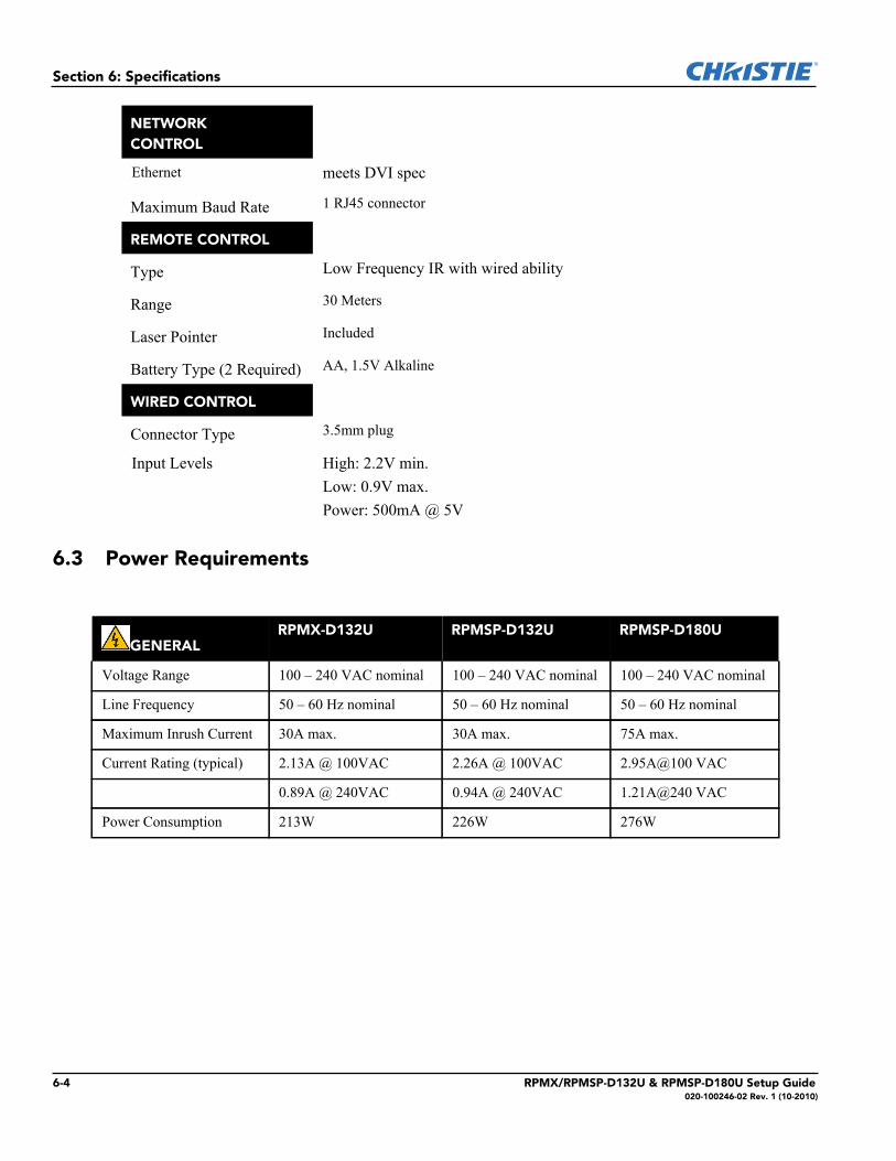
Section 6: Specifications
6.3 Power Requirements
NETWORK CONTROL
Ethernet meets DVI spec
Maximum Baud Rate 1 RJ45 connector
REMOTE CONTROL
Type Low Frequency IR with wired ability
Range 30 Meters
Laser Pointer Included
Battery Type (2 Required) AA, 1.5V Alkaline
WIRED CONTROL
Connector Type 3.5mm plug
Input Levels High: 2.2V min.Low: 0.9V max.Power: 500mA @ 5V
GENERALRPMX-D132U RPMSP-D132U RPMSP-D180U
Voltage Range 100 – 240 VAC nominal 100 – 240 VAC nominal 100 – 240 VAC nominal
Line Frequency 50 – 60 Hz nominal 50 – 60 Hz nominal 50 – 60 Hz nominal
Maximum Inrush Current 30A max. 30A max. 75A max.
Current Rating (typical) 2.13A @ 100VAC 2.26A @ 100VAC 2.95A@100 VAC
0.89A @ 240VAC 0.94A @ 240VAC 1.21A@240 VAC
Power Consumption 213W 226W 276W
6-4 RPMX/RPMSP-D132U & RPMSP-D180U Setup Guide020-100246-02 Rev. 1 (10-2010)
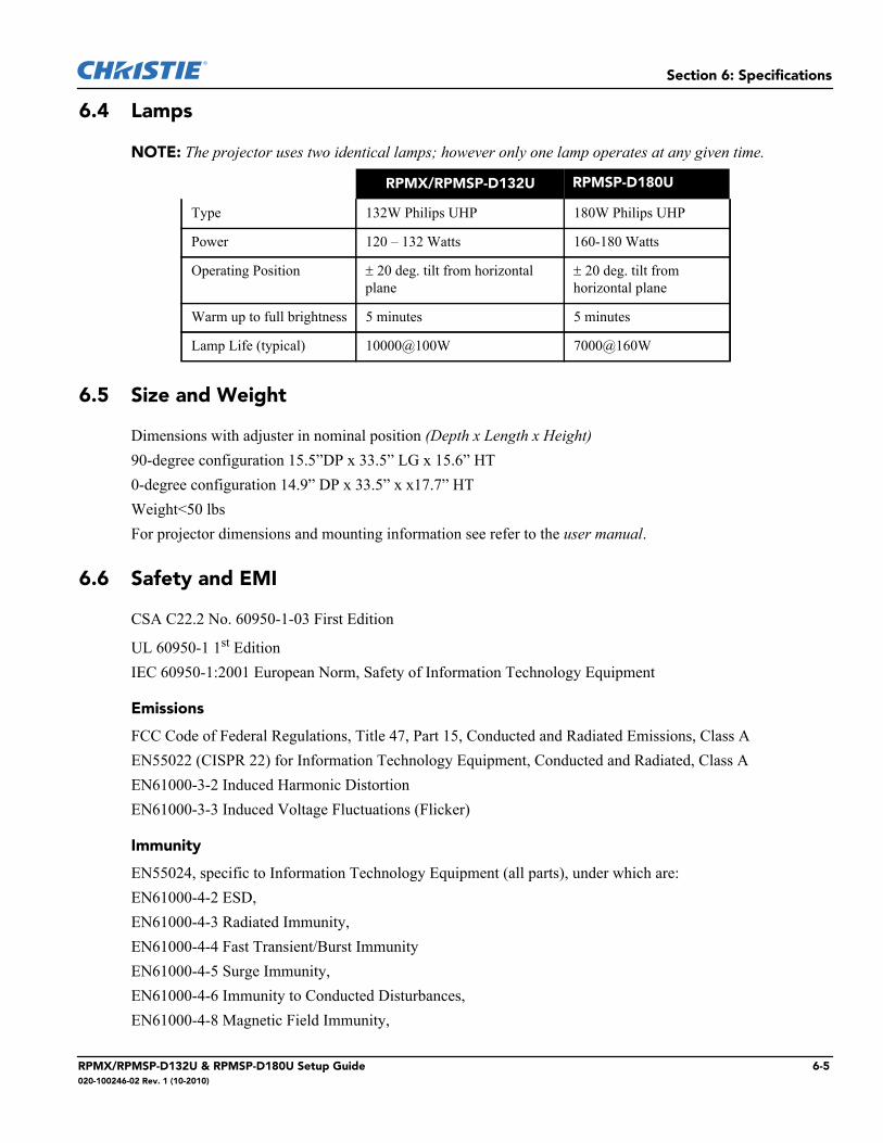
Section 6: Specifications
6.4 Lamps
NOTE: The projector uses two identical lamps; however only one lamp operates at any given time.
6.5 Size and Weight
Dimensions with adjuster in nominal position (Depth x Length x Height)90-degree configuration 15.5”DP x 33.5” LG x 15.6” HT0-degree configuration 14.9” DP x 33.5” x x17.7” HTWeight<50 lbsFor projector dimensions and mounting information see refer to the user manual.
6.6 Safety and EMI
CSA C22.2 No. 60950-1-03 First Edition
UL 60950-1 1st EditionIEC 60950-1:2001 European Norm, Safety of Information Technology Equipment
Emissions
FCC Code of Federal Regulations, Title 47, Part 15, Conducted and Radiated Emissions, Class AEN55022 (CISPR 22) for Information Technology Equipment, Conducted and Radiated, Class A EN61000-3-2 Induced Harmonic DistortionEN61000-3-3 Induced Voltage Fluctuations (Flicker)
Immunity
EN55024, specific to Information Technology Equipment (all parts), under which are:EN61000-4-2 ESD,EN61000-4-3 Radiated Immunity,EN61000-4-4 Fast Transient/Burst ImmunityEN61000-4-5 Surge Immunity,EN61000-4-6 Immunity to Conducted Disturbances,EN61000-4-8 Magnetic Field Immunity,
RRRPMX/RPMSP-D132U RPMSP-D180U
Type 132W Philips UHP 180W Philips UHP
Power 120 – 132 Watts 160-180 Watts
Operating Position 20 deg. tilt from horizontal plane
20 deg. tilt from horizontal plane
Warm up to full brightness 5 minutes 5 minutes
Lamp Life (typical) 10000@100W 7000@160W
RPMX/RPMSP-D132U & RPMSP-D180U Setup Guide 6-5020-100246-02 Rev. 1 (10-2010)
Section 6: Specifications
EN61000-4-11 Voltage Dips, Short Interruptions and Voltage Variations Immunity
6.7 Environmental
Operating Environment
Temperature 5C to 30C (40F to 86F)Humidity 20% - 80% non-condensingAltitude0 - 10,000ft, -5C to 50C
Non-Operating Environment
Temperature -25C to 70C with relative humidity varying between 0% to 95%Altitude 30,000ft, -25C to 70C
6.8 Standard Components
• Line Cord (rated, North American)• Configuration bracket (shipped loose, for vertical configuration)• 6, M6 screws (for installation of configuration bracket)• EM mounting bracket
6.9 Optional Accessories
User’s Kit (includes User Manual, IR Remote Keypad, Setup and Adjustment Tools)
Service manualDual frequency IR remote keypad
Optional Input Modules
RGB500 Input ModuleRGB400 Active Loop-Through Input ModuleRGB400 Buffered Amplifier Input ModulePC250 Analog Input Module Serial Digital Input ModuleDVI/DFP Input ModuleDual SD/HD-SDI Module
6-6 RPMX/RPMSP-D132U & RPMSP-D180U Setup Guide020-100246-02 Rev. 1 (10-2010)


1-2 Matrix StIM Setup Guide020-100397-02 Rev. 1 (10/10)
Section :
For the most current technical documentation, please visit www.christiedigital.com
USA – Cypressph: 714-236-8610
Canada – Kitchenerph: 519-744-8005
United Kingdomph: +44 118 977 8000
Germanyph: +49 2161 664540
Franceph: +33 (0) 1 41 21 44 04
Hungary/Eastern Europeph: +36 (0) 1 47 48 100
Singaporeph: +65 6877 8737
Shanghaiph: +86 21 6278 7708
Beijingph: +86 10 6561 0240
Koreaph: +82 2 702 1601
Japanph: +81 3 3599 7481
Corporate offi ces Worldwide offi ces