Embed Size (px)
Citation preview

METALROOFINGINSTALLATION
GUIDE
RPN & UPNMANUAL

TABLE OF CONTENTS
2
Preparation Requirements and Recommendations . . . . . . . . . . . . . . . . . . . . . . . . . . . . 3
Safety Considerations . . . . . . . . . . . . . . . . . . . . . . . . . . . . . . . . . . . . . . . . . . . . . . . . . . . 4
Tools Required . . . . . . . . . . . . . . . . . . . . . . . . . . . . . . . . . . . . . . . . . . . . . . . . . . . . . . . . . 4
Care and Handling of Mueller Sheet Metal . . . . . . . . . . . . . . . . . . . . . . . . . . . . . . . . . . 5
Standard Parts . . . . . . . . . . . . . . . . . . . . . . . . . . . . . . . . . . . . . . . . . . . . . . . . . . . . . . . . . . . . 6
Product Description . . . . . . . . . . . . . . . . . . . . . . . . . . . . . . . . . . . . . . . . . . . . . . . . . . . . . . . . . . 9
Storage. . . . . . . . . . . . . . . . . . . . . . . . . . . . . . . . . . . . . . . . . . . . . . . . . . . . . . . . . . . . . . . 9
RPN Panel - Standard Fastener Locations. . . . . . . . . . . . . . . . . . . . . . . . . . . . . . . . . . . 10
UPN Panel - Standard Fastener Locations . . . . . . . . . . . . . . . . . . . . . . . . . . . . . . . . . . 11
RPN Panel - Recommended Screw Placement Table . . . . . . . . . . . . . . . . . . . . . . . . . . . 12
UPN Panel - Recommended Screw Placement Table . . . . . . . . . . . . . . . . . . . . . . . . . . . 13
Detail Locator. . . . . . . . . . . . . . . . . . . . . . . . . . . . . . . . . . . . . . . . . . . . . . . . . . . . . . . . . 14
Beginning the ProjectStandard Eave Trim Installation . . . . . . . . . . . . . . . . . . . . . . . . . . . . . . . . . . . . . . . . . . . . . 15
Standard Eave Trim Installation with Gutter . . . . . . . . . . . . . . . . . . . . . . . . . . . . . . . . 16
Standard Adjustable Gable & Strip Installation . . . . . . . . . . . . . . . . . . . . . . . . . . . . . . 17
Starting and Ending Panel Installation . . . . . . . . . . . . . . . . . . . . . . . . . . . . . . . . . . . . . . . . . 18
High Side Residential Eave Trim Installation. . . . . . . . . . . . . . . . . . . . . . . . . . . . . . . . . . . 19
Valley Panel and Trim Installation . . . . . . . . . . . . . . . . . . . . . . . . . . . . . . . . . . . . . . . . . 20
Standard Ridge Row and Hip Installation. . . . . . . . . . . . . . . . . . . . . . . . . . . . . . . . . . . 21
Endwall to Roof Flashing Installation . . . . . . . . . . . . . . . . . . . . . . . . . . . . . . . . . . . . . . . . . . . 22
Sidewall Flashing Installation . . . . . . . . . . . . . . . . . . . . . . . . . . . . . . . . . . . . . . . . . . . . . . . 23
Roof Pitch Change Installation . . . . . . . . . . . . . . . . . . . . . . . . . . . . . . . . . . . . . . . . . . . . . 24
Standard Panel Endlap . . . . . . . . . . . . . . . . . . . . . . . . . . . . . . . . . . . . . . . . . . . . . . . . . 25
Chimney Flashing - Uphill and Downhill . . . . . . . . . . . . . . . . . . . . . . . . . . . . . . . . . . . 26
Chimney Flashing - Side and Vent . . . . . . . . . . . . . . . . . . . . . . . . . . . . . . . . . . . . . . . . 27
Contact Information . . . . . . . . . . . . . . . . . . . . . . . . . . . . . . . . . . . . . . . . . . . . . . . . . . . . . . 28
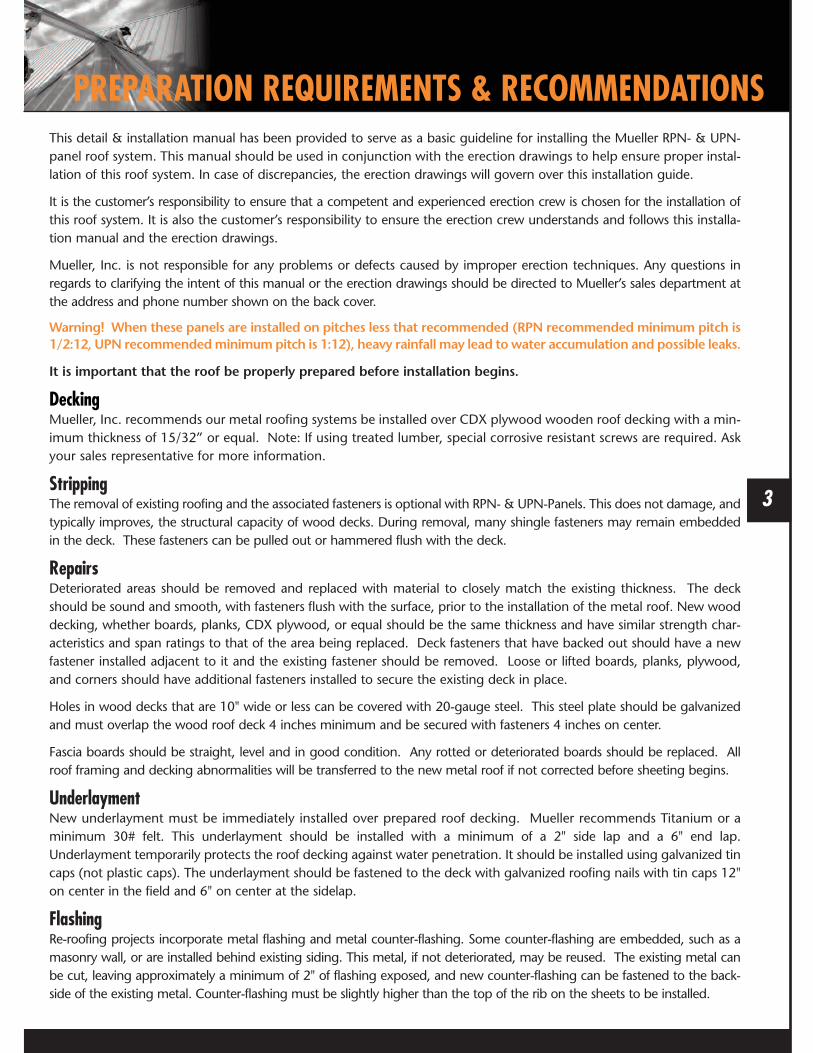
This detail & installation manual has been provided to serve as a basic guideline for installing the Mueller RPN- & UPN-panel roof system. This manual should be used in conjunction with the erection drawings to help ensure proper instal-lation of this roof system. In case of discrepancies, the erection drawings will govern over this installation guide.
It is the customer’s responsibility to ensure that a competent and experienced erection crew is chosen for the installation ofthis roof system. It is also the customer’s responsibility to ensure the erection crew understands and follows this installa-tion manual and the erection drawings.
Mueller, Inc. is not responsible for any problems or defects caused by improper erection techniques. Any questions inregards to clarifying the intent of this manual or the erection drawings should be directed to Mueller’s sales department atthe address and phone number shown on the back cover.
Warning! When these panels are installed on pitches less that recommended (RPN recommended minimum pitch is1/2:12, UPN recommendedminimumpitch is 1:12), heavy rainfall may lead to water accumulation and possible leaks.
It is important that the roof be properly prepared before installation begins.
DeckingMueller, Inc. recommends our metal roofing systems be installed over CDX plywood wooden roof decking with a min-imum thickness of 15/32” or equal. Note: If using treated lumber, special corrosive resistant screws are required. Askyour sales representative for more information.
StrippingThe removal of existing roofing and the associated fasteners is optional with RPN- & UPN-Panels. This does not damage, andtypically improves, the structural capacity of wood decks. During removal, many shingle fasteners may remain embeddedin the deck. These fasteners can be pulled out or hammered flush with the deck.
RepairsDeteriorated areas should be removed and replaced with material to closely match the existing thickness. The deckshould be sound and smooth, with fasteners flush with the surface, prior to the installation of the metal roof. New wooddecking, whether boards, planks, CDX plywood, or equal should be the same thickness and have similar strength char-acteristics and span ratings to that of the area being replaced. Deck fasteners that have backed out should have a newfastener installed adjacent to it and the existing fastener should be removed. Loose or lifted boards, planks, plywood,and corners should have additional fasteners installed to secure the existing deck in place.
Holes in wood decks that are 10" wide or less can be covered with 20-gauge steel. This steel plate should be galvanizedand must overlap the wood roof deck 4 inches minimum and be secured with fasteners 4 inches on center.
Fascia boards should be straight, level and in good condition. Any rotted or deteriorated boards should be replaced. Allroof framing and decking abnormalities will be transferred to the new metal roof if not corrected before sheeting begins.
UnderlaymentNew underlayment must be immediately installed over prepared roof decking. Mueller recommends Titanium or aminimum 30# felt. This underlayment should be installed with a minimum of a 2" side lap and a 6" end lap.Underlayment temporarily protects the roof decking against water penetration. It should be installed using galvanized tincaps (not plastic caps). The underlayment should be fastened to the deck with galvanized roofing nails with tin caps 12"on center in the field and 6" on center at the sidelap.
FlashingRe-roofing projects incorporate metal flashing and metal counter-flashing. Some counter-flashing are embedded, such as amasonry wall, or are installed behind existing siding. This metal, if not deteriorated, may be reused. The existing metal canbe cut, leaving approximately a minimum of 2" of flashing exposed, and new counter-flashing can be fastened to the back-side of the existing metal. Counter-flashing must be slightly higher than the top of the rib on the sheets to be installed.
3
PREPARATION REQUIREMENTS & RECOMMENDATIONS

4

5
SAFETY CONSIDERATIONS
Never Install Material if the Quality is in Question!
As with all major construction projects, safety should be aprimary concern. The erector or contractor should be sure thatall OSHA safety rules are followed and that job safety is strictlyadhered to.
The following safety equipment is highly recommendedwhen installing metal roofing:1. Safety rope and harness2. Hand protection3. Eye protection4. Hearing protection5. Soft rubber soled shoes
Metal roofing presents several specific safety issues:1. Metal roofing is extremely slick and does not provide
firm footing. Extreme care should be taken when:A. Working on roofs with very steep pitches.B. Working on roofs when moisture is present.C. Working on roofs when high wind is a factor.D. Working with long panels.
2. Metal edges are very sharp and should be handledwith care.
3. Care should be usedwhen lifting panels due to their weight.
4. Always check for overhead electrical lines and exercise carenot to have metal sheets come in contact with them.
5. All electrical tools should be inspected regularly fordamaged cases or frayed electric cords. Extension cordsshould be inspected for damaged or frayed insulation.Tools which do not meet good safety standards shouldnot be used.
CAUTION: Care should be taken when cutting sheets. Eye andhearing protection are important.
NOTE: Always wear rubber soled work boots. When on the roof,use OSHA approved protection devices such as safety lines,safety nets or catch platforms.
Unsecured Panels May Slip If Stepped On!Never step on a single unsecured roof panel, or a stack ofroof panels laying unattached on the roof. Secure each endof the panel with clamps or appropriate fasteners andplace walkboards of adequate size and strength in the flatof any panels not fully secured to the roof and supportedby panels on each side. Walkboards should run the fulllength of the panel and be fastened together by drilling ahole near the end of each board and tied with rope to thenext board. Cut a groove in the bottom of each board sothe board will lie flat and not tip back and forth because ofthe rope.
TOOLS REQUIREDThe following list of tools is recommended when installing metal roofing:
1. Aviation snips - left, right, straight 6. Square 11. Broom 16. Fire extinguisher
2. Screw gun 2500 RPM with appropriate nut drivers 7. Straight edge 12. Extension cords 17. Saw horses
3. Tape measure 8. Chalk line 13. Ladder 18. First aid kit
4. Caulking gun 9. Vise grips 14. Hammer 19. Tarp
5. Safety equipment: goggles, hard hat, 10. Gloves 15. Drill bits 20. Electric shear or nibblerand soft rubber soled shoes
CAUTION: Whenever using any type of power equipment, it is important to follow the manufacturer’s recommendationfor use. Always be aware of the danger involved when using electric or air powered equipment.
Underlayment: The underlayment should be one layer
of Titanium or 30# felt. The Titanium should have a 2"
side lap and a 6” end lap. The underlayment should be
fastened to the deck with galvanized roofing nails with
tin caps 12" on center in the field and 6" on center at
the sidelap.
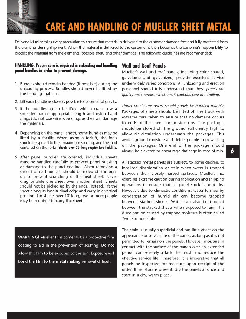
HANDLING: Proper care is required in unloading and handlingpanel bundles in order to prevent damage.
1. Bundles should remain banded (if possible) during theunloading process. Bundles should never be lifted bythe banding material.
2. Lift each bundle as close as possible to its center of gravity.
3. If the bundles are to be lifted with a crane, use aspreader bar of appropriate length and nylon bandslings (do not Use wire rope slings as they will damagethe material).
4. Depending on the panel length, some bundles may belifted by a forklift. When using a forklift, the forksshould be spread to their maximum spacing, and the loadcentered on the forks. Sheets over 25' long require two forklifts.
5. After panel bundles are opened, individual sheetsmust be handled carefully to prevent panel bucklingor damage to the panel coating. When removing asheet from a bundle it should be rolled off the bun-dle to prevent scratching of the next sheet. Neverdrag or slide one sheet over another sheet. Sheetsshould not be picked up by the ends. Instead, lift thesheet along its longitudinal edge and carry in a verticalposition. For sheets over 10' long, two or more peoplemay be required to carry the sheet.
Wall and Roof PanelsMueller’s wall and roof panels, including color coated,galvalume and galvanized, provide excellent serviceunder widely varied conditions. All unloading and erectionpersonnel should fully understand that these panels arequality merchandise which merit cautious care in handling.
Under no circumstances should panels be handled roughly.Packages of sheets should be lifted off the truck withextreme care taken to ensure that no damage occursto ends of the sheets or to side ribs. The packagesshould be stored off the ground sufficiently high toallow air circulation underneath the packages. Thisavoids ground moisture and deters people from walkingon the packages. One end of the package shouldalways be elevated to encourage drainage in case of rain.
All stacked metal panels are subject, to some degree, tolocalized discoloration or stain when water is trappedbetween their closely nested surfaces. Mueller, Inc.exercises extreme caution during fabrication and shippingoperations to ensure that all panel stock is kept dry.However, due to climactic conditions, water formed bycondensation of humid air can become trappedbetween stacked sheets. Water can also be trappedbetween the stacked sheets when exposed to rain. Thisdiscoloration caused by trapped moisture is often called“wet storage stain.”
The stain is usually superficial and has little effect on theappearance or service life of the panels as long as it is notpermitted to remain on the panels. However, moisture incontact with the surface of the panels over an extendedperiod can severely attack the finish and reduce theeffective service life. Therefore, it is imperative that allpanels be inspected for moisture upon receipt of theorder. If moisture is present, dry the panels at once andstore in a dry, warm place.
Delivery: Mueller takes every precaution to ensure that material is delivered to the customer damage-free and fully protected fromthe elements during shipment. When the material is delivered to the customer it then becomes the customer’s responsibility toprotect the material from the elements, possible theft, and other damage. The following guidelines are recommended:
6
CARE AND HANDLING OF MUELLER SHEET METAL
WARNING! Mueller trim comes with a protective film
coating to aid in the prevention of scuffing. Do not
allow this film to be exposed to the sun. Exposure will
bond the film to the metal making removal difficult.

7
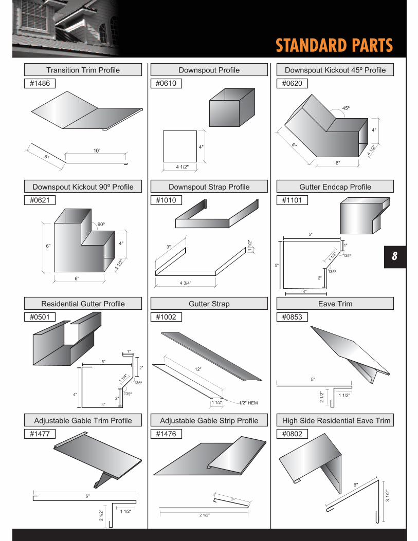
STANDARD PARTS
8
STANDARD PARTS

STANDARD PARTS
9

10
PRODUCT DESCRIPTION• 36" Coverage• 26 Gauge
For color selections,please request a color chart.
G-90 Galvanized (NO WARRANTY)Galvalume Plus (20 Yr. WARRANTY)
Limited Paint Warranties(UP TO 30 YEAR WARRANTIES)
STORAGE: It is recommended that sheets be kept covered andout of the elements if at all possible. If sheets are to be storedoutside, the following precautions should be observed:
1. The storage area should be reasonably level, and located soas to minimize handling.
2. When stored on bare ground, place plastic ground coverunder the bundles to minimize condensation on the sheetsfrom ground moisture.
3. Store bundles at least 12 inches above ground level to allowair circulation beneath the bundle, and to prevent damagefrom rising water.
4. Elevate one end of each bundle slightly to permit runoff ofmoisture from the top of the bundle or from betweensheets. A waterproof cover should be placed loosely overthe bundles to allow for air circulation under the cover.
5. Inspect stored bundles daily and repair any tears orpunctures in the waterproof cover.
6. Re-cover opened bundles at the end of each work day toprevent subsequent moisture damage.
Checking order at time of delivery:Check each order carefully, as it is unloaded. Report anyobvious damage or shortages to the carrier immediately. Ifdamage or shortages are noted after delivery (at time ofunpacking) notify your Mueller representative immediately.Have invoice numbers and detailed descriptions of thedamage or shortage available. These procedures are foryour protection. A shortage or damage discovered latercan be caused by theft, misplacement, mishandling orother causes and is not the responsibility of Mueller, Inc.
STORAGE
Note: Always remove metal filings from surface of
panels at the end of each work period. Rusting filings
can destroy the paint finish and void warranty.

Details are subject to change without prior notice.
11
STANDARD FASTENER LOCATIONS
Gable
a a
ZONE 3
ZONE 2
Ridge
Eave
a
ZONE 1
RPN-PANEL
Note: Dimension (a) is defined as 10% of the minimum width ofthe building or 40% of the mean height of the roof, whichever issmaller, however, (a) cannot be less than either 4% of the mini-mum width of the building or 3 feet.
ATTACHMENT TO PLYWOOD ATTACHMENT TO 1 X 4 WOOD PURLIN
Warning! RPN Panel should not be installedon a roof that is less than a 1/2:12 pitch.When this panel is installed on pitches lessthan 1/2:12, heavy rainfall may lead to wateraccumulation and possible leaks.

12
STANDARD FASTENER LOCATIONS
Details are subject to change without prior notice.
Gable
a a
ZONE 3
ZONE 2
Ridge
Eave
a
ZONE 1
UPN-PANEL
Note: Dimension (a) is defined as 10% of the minimum width ofthe building or 40% of the mean height of the roof, whichever issmaller, however, (a) cannot be less than either 4% of the mini-mum width of the building or 3 feet.
ATTACHMENT TO PLYWOOD ATTACHMENT TO 1 X 4 WOOD PURLINTYPE 1: FASTENER LOCATION
TYPE 2: FASTENER LOCATION
Warning! UPN Panel should not be installedon a roof that is less than a 1:12 pitch. Whenthis panel is installed on pitches less than 1:12,heavy rainfall may lead to water accumulationand possible leaks.

Details are subject to change without prior notice.
RECOMMENDED SCREW PLACEMENT TABLERPN-PANEL
Note: If using treated lumber, special corrosive resistant screws are required. Ask your sales representative for more information.
Zone FASTENER SUBSTRATE90
ON CENTERSPACING
100
ON CENTERSPACING
110
ON CENTERSPACING
120
ON CENTERSPACING
130
ON CENTERSPACING
140
ON CENTERSPACING
Zone 1 #12-11 X 1” 15/32” CDX
19/32” CDX
7/16” OSB
1x4 Wood Purlins
Type 1, 36”
Type 1, 36”
Type 1, 30”
Type 1, 24”
Type 1, 30”
Type 1, 30”
Type 2, 30”
Type 1, 24”
Type 1, 30”
Type 1, 30”
N/A
Type 1, 24”
Type 1, 30”
Type 1, 30”
N/A
Type 1, 24”
Type 1, 30”
Type 1, 30”
N/A
Type 1, 24”
Type 1, 30”
Type 1, 30”
N/A
N/A
Zone 2 #12-11 X 1” 15/32” CDX
19/32” CDX
7/16” OSB
1x4 Wood Purlins
Type 1, 30”
Type 1, 30”
Type 2, 30”
Type 1, 24”
Type 1, 30”
Type 1, 30”
Type 2, 30”
Type 1, 24”
Type 1, 30”
Type 1, 30”
N/A
Type 1, 24”
Type 1, 30”
Type 1, 30”
N/A
Type 1, 24”
Type 2, 24”
Type 2, 24”
N/A
Type 1, 24”
Type 2, 24”
Type 2, 24”
N/A
N/A
Zone 3 #12-11 X 1” 15/32” CDX
19/32” CDX
7/16” OSB
1x4 Wood Purlins
Type 1, 30”
Type 1, 30”
Type 2, 30”
Type 1, 24”
Type 1, 30”
Type 1, 30”
Type 2, 30”
Type 1, 24”
Type 2, 24”
Type 2, 24”
N/A
Type 2, 24”
Type 2, 24”
Type 2, 24”
N/A
Type 2, 24”
Type 2, 12”
Type 2, 12”
N/A
Type 2, 24”
Type 2, 12”
Type 2, 12”
N/A
N/A
Zone FASTENER SUBSTRATE90
ON CENTERSPACING
100
ON CENTERSPACING
110
ON CENTERSPACING
120
ON CENTERSPACING
130
ON CENTERSPACING
140
ON CENTERSPACING
Zone 1 #12-11 X 1” 15/32” CDX
19/32” CDX
7/16” OSB
1x4 Wood Purlins
Type 1, 36”
Type 1, 36”
Type 1, 30”
Type 1, 24”
Type 1, 30”
Type 1, 30”
Type 2, 30”
Type 1, 24”
Type 1, 30”
Type 1, 30”
Type 2, 30”
Type 1, 24”
Type 1, 30”
Type 1, 30”
Type 2, 30”
Type 1, 24”
Type 1, 30”
Type 1, 30”
Type 2, 30”
Type 1, 24”
Type 1, 30”
Type 1, 30”
Type 2, 30”
Type 1, 24”
Zone 2 #12-11 X 1” 15/32” CDX
19/32” CDX
7/16” OSB
1x4 Wood Purlins
Type 1, 30”
Type 1, 30”
Type 2, 30”
Type 1, 24”
Type 1, 30”
Type 1, 30”
Type 2, 30”
Type 1, 24”
Type 1, 30”
Type 1, 30”
Type 2, 30”
Type 1, 24”
Type 1, 30”
Type 1, 30”
Type 2, 30”
Type 1, 24”
Type 1, 30”
Type 1, 30”
Type 2, 30”
Type 1, 24”
Type 1, 30”
Type 1, 30”
Type 2, 30”
Type 1, 24”
Zone 3 #12-11 X 1” 15/32” CDX
19/32” CDX
7/16” OSB
1x4 Wood Purlins
Type 1, 30”
Type 1, 30”
Type 2, 30”
Type 1, 24”
Type 1, 30”
Type 1, 30”
Type 2, 30”
Type 1, 24”
Type 1, 30”
Type 1, 30”
Type 2, 30”
Type 1, 24”
Type 1, 30”
Type 1, 30”
Type 2, 30”
Type 1, 24”
Type 1, 30”
Type 1, 30”
Type 2, 30”
Type 1, 24”
Type 1, 30”
Type 1, 30”
Type 2, 30”
Type 1, 24”
WIND SPEED ZONE
FASTENING SCHEDULE SPACING ALONG PANEL NAIL STRIPWith < 30’-0” mean eave height - 3:12 to 6:12 pitch for 90-140 mph wind speeds based on ASCE 7-93
WIND SPEED ZONE
FASTENING SCHEDULE SPACING ALONG PANEL NAIL STRIPWith < 30’-0” mean eave height - 7:12 to 12:12 pitch for 90-140 mph wind speeds based on ASCE 7-93

Details are subject to change without prior notice.
RECOMMENDED SCREW PLACEMENT TABLEUPN-PANEL
Zone FASTENER SUBSTRATE90
ON CENTERSPACING
100
ON CENTERSPACING
110
ON CENTERSPACING
120
ON CENTERSPACING
130
ON CENTERSPACING
140
ON CENTERSPACING
Zone 1 #12-11 X 1” 15/32” CDX
19/32” CDX
7/16” OSB
1x4 Wood Purlins
Type 1, 36”
Type 1, 36”
Type 1, 30”
Type 1, 24”
Type 1, 30”
Type 1, 30”
Type 2, 30”
Type 1, 24”
Type 1, 30”
Type 1, 30”
N/A
Type 1, 24”
Type 1, 30”
Type 1, 30”
N/A
Type 1, 24”
Type 1, 30”
Type 1, 30”
N/A
Type 1, 24”
Type 1, 30”
Type 1, 30”
N/A
N/A
Zone 2 #12-11 X 1” 15/32” CDX
19/32” CDX
7/16” OSB
1x4 Wood Purlins
Type 1, 30”
Type 1, 30”
Type 2, 30”
Type 1, 24”
Type 1, 30”
Type 1, 30”
Type 2, 30”
Type 1, 24”
Type 1, 30”
Type 1, 30”
N/A
Type 1, 24”
Type 1, 30”
Type 1, 30”
N/A
Type 1, 24”
Type 2, 24”
Type 2, 24”
N/A
Type 1, 24”
Type 2, 24”
Type 2, 24”
N/A
N/A
Zone 3 #12-11 X 1” 15/32” CDX
19/32” CDX
7/16” OSB
1x4 Wood Purlins
Type 1, 30”
Type 1, 30”
Type 2, 30”
Type 1, 24”
Type 1, 30”
Type 1, 30”
Type 2, 30”
Type 1, 24”
Type 2, 24”
Type 2, 24”
N/A
Type 2, 24”
Type 2, 24”
Type 2, 24”
N/A
Type 2, 24”
Type 2, 12”
Type 2, 12”
N/A
Type 2, 24”
Type 2, 12”
Type 2, 12”
N/A
N/A
Zone FASTENER SUBSTRATE90
ON CENTERSPACING
100
ON CENTERSPACING
110
ON CENTERSPACING
120
ON CENTERSPACING
130
ON CENTERSPACING
140
ON CENTERSPACING
Zone 1 #12-11 X 1” 15/32” CDX
19/32” CDX
7/16” OSB
1x4 Wood Purlins
Type 1, 36”
Type 1, 36”
Type 1, 30”
Type 1, 24”
Type 1, 30”
Type 1, 30”
Type 2, 30”
Type 1, 24”
Type 1, 30”
Type 1, 30”
Type 2, 30”
Type 1, 24”
Type 1, 30”
Type 1, 30”
Type 2, 30”
Type 1, 24”
Type 1, 30”
Type 1, 30”
Type 2, 30”
Type 1, 24”
Type 1, 30”
Type 1, 30”
Type 2, 30”
Type 1, 24”
Zone 2 #12-11 X 1” 15/32” CDX
19/32” CDX
7/16” OSB
1x4 Wood Purlins
Type 1, 30”
Type 1, 30”
Type 2, 30”
Type 1, 24”
Type 1, 30”
Type 1, 30”
Type 2, 30”
Type 1, 24”
Type 1, 30”
Type 1, 30”
Type 2, 30”
Type 1, 24”
Type 1, 30”
Type 1, 30”
Type 2, 30”
Type 1, 24”
Type 1, 30”
Type 1, 30”
Type 2, 30”
Type 1, 24”
Type 1, 30”
Type 1, 30”
Type 2, 30”
Type 1, 24”
Zone 3 #12-11 X 1” 15/32” CDX
19/32” CDX
7/16” OSB
1x4 Wood Purlins
Type 1, 30”
Type 1, 30”
Type 2, 30”
Type 1, 24”
Type 1, 30”
Type 1, 30”
Type 2, 30”
Type 1, 24”
Type 1, 30”
Type 1, 30”
Type 2, 30”
Type 1, 24”
Type 1, 30”
Type 1, 30”
Type 2, 30”
Type 1, 24”
Type 1, 30”
Type 1, 30”
Type 2, 30”
Type 1, 24”
Type 1, 30”
Type 1, 30”
Type 2, 30”
Type 1, 24”
WIND SPEED ZONE
FASTENING SCHEDULE SPACING ALONG PANEL NAIL STRIPWith < 30’-0” mean eave height - 3:12 to 6:12 pitch for 90-140 mph wind speeds based on ASCE 7-93
WIND SPEED ZONE
FASTENING SCHEDULE SPACING ALONG PANEL NAIL STRIPWith < 30’-0” mean eave height - 7:12 to 12:12 pitch for 90-140 mph wind speeds based on ASCE 7-93
15
DETAIL LOCATOR
Details are subject to change without prior notice.
1
4
7
28
35
9
6
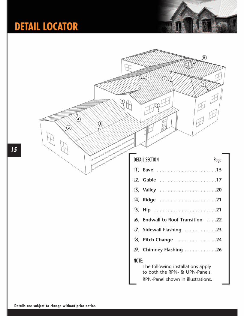
DETAIL SECTION Page
1 Eave . . . . . . . . . . . . . . . . . . . . . .15
2 Gable . . . . . . . . . . . . . . . . . . . . .17
3 Valley . . . . . . . . . . . . . . . . . . . . .20
4 Ridge . . . . . . . . . . . . . . . . . . . . .21
5 Hip . . . . . . . . . . . . . . . . . . . . . . .21
6 Endwall to Roof Transition . . . .22
7 Sidewall Flashing . . . . . . . . . . . .23
8 Pitch Change . . . . . . . . . . . . . . .24
9 Chimney Flashing . . . . . . . . . . . .26
NOTE:The following installations applyto both the RPN- & UPN-Panels.
RPN-Panel shown in illustrations.

2 1/2" APPROXIMATEDISTANCE
2 1/2" APPROXIMATEDISTANCE
1. Install the eave trim by sliding it underneath the underlayment and securing it to the roof surface withwafer head screws on 5’ centers.
2. There are no screws or nails to be placed in the exposed fascia of the trim.
3. At the corners, cut the eave trim 1 1/2” long and prepare the ends with tabs to receive the gable trim.
16
BEGINNING THE PROJECT
Details are subject to change without prior notice.
STANDARD EAVE TRIM INSTALLATION
17
STANDARD EAVE TRIM INSTALLATION WITH GUTTER
Details are subject to change without prior notice.
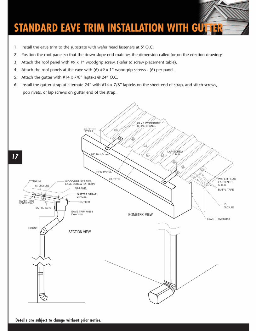
1. Install the eave trim to the substrate with wafer head fasteners at 5’ O.C.
2. Position the roof panel so that the down slope end matches the dimension called for on the erection drawings.
3. Attach the roof panel with #9 x 1” woodgrip screw. (Refer to screw placement table).
4. Attach the roof panels at the eave with (6) #9 x 1” woodgrip screws - (6) per panel.
5. Attach the gutter with #14 x 7/8” lapteks @ 24” O.C.
6. Install the gutter strap at alternate 24” with #14 x 7/8” lapteks on the sheet end of strap, and stitch screws,
pop rivets, or lap screws on gutter end of the strap.

18
STANDARD ADJUSTABLE GABLE & STRIP INSTALLATION
Details are subject to change without prior notice.
1. If valley trim is intersecting the gable, the valley must be installed first.
2. Pre-drill 1/8” holes on 12” centers along the length of adjustable gable strip #1476.
3. Butyl tape should be applied to the bottom of the strip covering pre-drilled holes. Place the stripthe desired distance from the outside edge of the gable trim (optimal distance 2”), making sure itis aligned parallel to the gable, perpendicular to the eave line and between the open hem at theedge of the adjustable gable trim and the outside of the trim.
4. The adjustable strip is attached to the roof with wafer head screws on 12” centers from eave toridge using pre-drilled holes, making sure the screws are applied through the butyl tape. Thiscondition exists in both Starting Panel and End Panel Installation.
1. Starting at the corner, install the adjustable gable trim along thesloping gable, placing it on top of the underlayment.
2. Attach with wafer head screws 5’ on centers(adjustable strip applied after valley trim).
3. Slide gable trim over eave trim at corner.
4. At the peak, one gable trim should be cutvertical to the ground and overlap at thejunction of the two gable trims.

19
STARTING AND ENDING PANEL INSTALLATION
Details are subject to change without prior notice.
Starting Panel1. Apply adjustable strip as previously instructed.
2. Remove the first rib of the panel, making a straight cut the length of the panel.
3. Apply butyl tape continuously down the length of the adjustable strip, covering the wafer head screw.
4. Insert the cut edge of the panel into the strip, making sure the panel is seated fully into the strip.
5. Attach the panel to the roof with #9 x 1” woodgrip screws on the required centers.
6. Apply 1/2” x 3/32” butyl tape continuously on the top of the outside rib before applying the next panel.
Ending Panel1. Remove the last rib of the panel at a point that is inside the adjustment portion
of the gable trim, making a straight cut the length of the panel (optimal 2” from gable edge).
2. Apply adjustable strip as previously instructed.
3. Test apply the panel to assure proper fit.
4. Apply butyl tape and apply last panel into strip, making appropriate panel lap.

20
HIGH SIDE RESIDENTIAL EAVE TRIM INSTALLATION
Installations apply to both RPN- & UPN-Panels. RPN-Panel shown in illustration.
1. Ensure the roof panel is installed completely. Reference the erection drawings for the top dimension to ensurecorrect installation.
2. Install the outside closure on the top of the roof panel, make sure the closure is in line with the extended flange ofthe high side eave trim.
3. Install the high side eave trim.
4. Attach the high side eave trim with lap screws @ 12” O.C. locate the screws on the high ribs toprevent dimpling of the eave trim due to over-tightening.

21
VALLEY PANEL AND TRIM INSTALLATION
Details are subject to change without prior notice.
1. Start at the low end, trim and place the valley flashing. The valley end should overhang the eave trim 1”.
2. If there is an end lap required in the valley pieces, caulk and lap at least 8”.
3. Use wafer head screws on 5’ centers to secure the valley in place along the outside edge.
4. Hem the edges of the valley over the eave trim, after trimming the center “V” back 1” to align with theedge of the eave. Leave a tab to bend and cover the exposed opening of the center “V”.
5. Place butyl tape on the upper surface of the valley 6” up slope from the “V” of the valley trim,before applying intersecting panels.
6. Field cut the panels that intersect the valley holding the end of the panel 4” back from the “V” of thevalley trim and parallel to the “V” of the valley.
7. Attach panel at valley using eave screw requirements for panel being installed.
ExpandableClosure for Hips
STANDARD RIDGE ROW and HIP INSTALLATION
Installations apply to both RPN- & UPN-Panels. RPN-Panel shown in illustration.
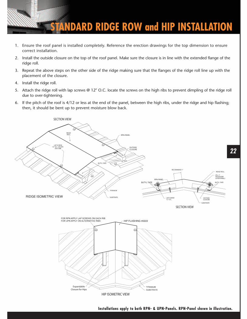
1. Ensure the roof panel is installed completely. Reference the erection drawings for the top dimension to ensurecorrect installation.
2. Install the outside closure on the top of the roof panel. Make sure the closure is in line with the extended flange of theridge roll.
3. Repeat the above steps on the other side of the ridge making sure that the flanges of the ridge roll line up with theplacement of the closure.
4. Install the ridge roll.
5. Attach the ridge roll with lap screws @ 12" O.C. locate the screws on the high ribs to prevent dimpling of the ridge rolldue to over-tightening.
6. If the pitch of the roof is 4/12 or less at the end of the panel, between the high ribs, under the ridge and hip flashing;then, it should be bent up to prevent moisture blow back.
22

23
ENDWALL TO ROOF FLASHING INSTALLATION
Details are subject to change without prior notice.
1. Insert the endwall flashing (#0726) behind the existing wall counter-flashing and attach to the wall usingappropriate fasteners. Make sure the receiver hem of the endwall flashing is resting on the top of the roof sheet rib.If required, cap the ends of the trim by cutting and folding a tab. Remove the hems before making the folds.
2. If there is no counter-flashing, install counter-flashing using appropriate fasteners.
3. Install the outside closure on top of the roof panel. Make sure the closure is in line with the lower flangeof the endwall trim.
4. Install the endwall trim by attaching with lap screws @ 12” O.C. Locate the screws at the high ribs toprevent dimpling of the endwall trim due to over-tightening.
5. All end laps should be at least 4”. Remove 4” of the hem on the overlapping piece and secure to theoverlapped piece with caulk and stitch screws.
24
SIDEWALL FLASHING INSTALLATION
Installations apply to both RPN- & UPN-Panels. RPN-Panel shown in illustration.
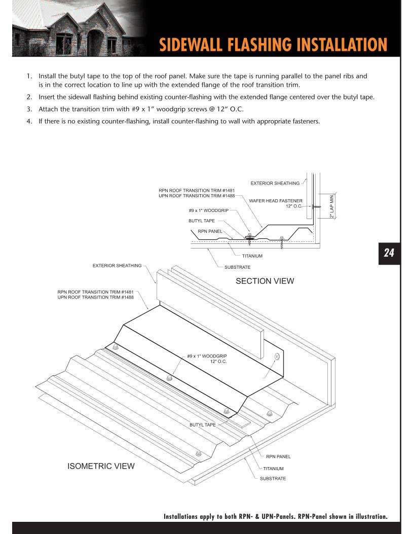
1. Install the butyl tape to the top of the roof panel. Make sure the tape is running parallel to the panel ribs andis in the correct location to line up with the extended flange of the roof transition trim.
2. Insert the sidewall flashing behind existing counter-flashing with the extended flange centered over the butyl tape.
3. Attach the transition trim with #9 x 1” woodgrip screws @ 12“ O.C.
4. If there is no existing counter-flashing, install counter-flashing to wall with appropriate fasteners.

25
ROOF PITCH CHANGE INSTALLATION
Details are subject to change without prior notice.
1. Apply lower panels.
2. Install the transition flashing (#1486) making sure the bottom portion of the flashing is at the same pitchas the lower panels. Attach to decking 1” from top of flashing with wafer head screws on 5’ centers.
3. Install outside closure on top of the lower panel. Make sure the closure is in line with the lower flangeof the transition trim.
4. Attach using lap screw, 12” on center at the rib.
5. All trim end laps should be at least 4”. Secure to the overlapped piece with caulk and stitch screws.
6. Cap the ends of the trim by cutting and folding a tab that attaches to the gable trim. Capping is usually easier todo before the trim is installed. If done after the trim is installed, be sure and leave 6” of the trim overhanging toallow enough material for the cut and folds.
7. Before applying the upper panels, place a row of butyl tape continuously along the trim at a point where thescrews holding the lower end of the upper panel will go through the butyl tape. This is usually 4” uphill from thebottom of the upper sheet. Use eave screw pattern.

26
STANDARD PANEL ENDLAP
Installations apply to both RPN- & UPN-Panels. RPN-Panel shown in illustration.
1. Ensure the lower panel is installed completely (except for the top fasteners).
2. Install the tape sealant 10” from the top of the lower panel. Do not remove the paper backing fromthe tape sealant until upper roof panel lap and the top dimension has been confirmed. Referencethe erection drawings for the top dimension.
3. Position the roof panel so that a 12” panel lap is achieved.
4. Remove paper backing and compress the sealant between the upper and lower roof panels.
5. Attach the upper roof panel through the lower roof panel with #9 x 1" (min.) woodgrip screws,(6) per panel making sure the screw line is above the tape sealant.

The uphill flashing will be 4” wider than the width of the
curb (2” on each side). Cut an 1/8” slot in the two uphill
corners of the panel slightly wider than 2 1/16”, so the
uphill flashing can slide through the two slots.27
CHIMNEY INSTALLATION
Details are subject to change without prior notice.
CHIMNEY FLASHING - UPHILL AND DOWNHILL
1. Trim both ends of the uphill and downhill sides of theflashing as indicated.
2. Slide the uphill flashing into the slots of the roofing andapply liberal amount of tube caulk.
DOWNHILL
UPHILL
UPHILL

28
CHIMNEY INSTALLATION
CHIMNEY FLASHING - SIDE
FLASHING - VENTProcedures:1. Trim the opening in the flashing to 20% smaller than
the pipe diameter.
2. Slide the flashing down over the pipe.
3. Seal between the flashing and the roofing withtube caulk and set the flashing.
4. Form the flashing to fit the profile of the roof.
5. Fasten the flashing with woodgrip screws 1” on centers.
Note:In many cases it may be easier to locatevent/pipe flashing in the flat area of the roof panel(as shown) rather than have the penetration occur at apanel rib. Determining panel layout prior to installationoften simplifies flashing installation.
1. Trim and bend the right side flashing as indicated.Trim the left side in a similar fashion.
Note:The left and right side flashing aremirror images of each other.
SIDE
SIDE
SIDE
Installations apply to both RPN- & UPN-Panels. RPN-Panel shown in illustration.

Mueller’s #1, 26 gauge, R & UPanels have received theUnderwriter’s Laboratory UL2218Approved Class 4 Premium Rating
M-RUMANUAL-REV.05/11
FIND OUT MORE ABOUT MUELLER, INC.
Call877-2-MUELLER (877-268-3553)This toll-free number connects you to the branch nearest you.We have more than 25 locations across the Southwest.
Clickwww.MuellerInc.comOur interactive website offers photos and detailed product information.
Come byOur local branches are staffed with experts who arealways happy to answer any questions you may have.