Embed Size (px)
Citation preview
Prepared by Doosan Babcock Energy Limited for the Health and Safety Executive 2009
Health and Safety Executive
Evaluation of the effectiveness of non-destructive testing screening methods for in-service inspection
RR659Research Report
Fraser HardieDoosan Babcock Energy LimitedPorterfield RoadRenfrewPA4 8DJ
A wide range of engineering plant is subject to periodic in-service inspection in order to ensure continued safe and economic operation. The inspections are often performed by traditional NDT methods such as routine ultrasonics, magnetic particle inspection, dye penetrant inspection, visual inspection and radiography. These can be highly sensitive but the rate of coverage is often slow, so that full coverage can be prohibitively expensive, and extensive preparation for inspection may be required (eg access for internal visual inspection, removal of insulation for external inspection etc.) There are also many situations where geometry or access prevents the use of conventional inspection methods.
Over recent years a wide range of advanced NDT techniques has evolved. These techniques provide large area screening of a component for significant degradation. Some of the techniques can be rapidly applied, much quicker than a more detailed, conventional inspection. Generally, the screening techniques are less sensitive than the more traditional methods. They also provide a means of inspecting areas which would otherwise be ‘uninspectable’. Examples include long range ultrasonics, pulsed eddy current techniques and saturated low frequency eddy current techniques.
There is a lack of objective information on the capability and limitations of screening techniques which is needed in order to allow judgement on their suitability for a particular application. Information is required on how to select a particular technique, what it can detect (as well as what it can miss), and what the level of confidence is in no degradation being present if none is detected.
The aim of this document is to provide an objective source of information on the capability and limitations of screening techniques and to provide information on their use to those involved in plant operation and maintenance.
This report and the work it describes were funded by the Health and Safety Executive (HSE). Its contents, including any opinions and/or conclusions expressed, are those of the author alone and do not necessarily reflect HSE policy.
Evaluation of the effectiveness of non-destructive testing screening methods for in-service inspection
HSE Books
Health and Safety Executive

© Crown copyright 2009
First published 2009
All rights reserved. No part of this publication may be reproduced, stored in a retrieval system, or transmitted in any form or by any means (electronic, mechanical, photocopying, recording or otherwise) without the prior written permission of the copyright owner.
Applications for reproduction should be made in writing to:Licensing Division, Her Majesty’s Stationery Office,St Clements House, 2-16 Colegate, Norwich NR3 1BQor by e-mail to [email protected]
2

3
Foreword
This document is aimed specifically at assisting the purchaser in the effective selection of screening techniques for in-service inspection and subsequent use and understanding of the data generated by the inspection. The screening techniques are generally specialised NDT inspection techniques aimed at detection of corrosion in pipes and vessels
This document has been written as part of the work coordinated by Doosan Babcock as part of Project GSP 236. A list of the members of the steering committee is given in Appendix 4.
The HSE was a member of the steering committee and would like to thank the other members of the committee for allowing the release of commercial information to be published as a HSE document.
H Bainbridge Principal Specialist Inspector Health and Safety Executive

4
CONTENTS
Foreword 3
Definitions 5
1. Introduction. 7
2. Basis for Performing Screening. 10
3. Information Required to Select a Particular Screening Technique. 12
4. Screening Inspection Plan. 15
5. Inspection Preparation, Implementation and Reporting. 20
6. References. 27
Appendices
A1 Review of Screening Techniques for In-Service Inspection
A2 Table of Capabilities of Screening Techniques for In-Service Inspection.
A3 In-Service Screening Inspection Plan.
A4 GSP236 Steering Committee Members
A5 Datasheets
A6 Statistical Methods
5
DEFINITIONS
In the context of this document the following definitions apply. In certain cases these definitions are the same as, or are based on, those which appear in other documents such as those of the British Personnel Certification in Non-Destruction Testing (PCN) scheme.
Screening Technique A loose term categorising techniques which might be less sensitive than traditional NDT methods but which may, for example, provide economic large area coverage, or are more tolerant to restrictive access, geometry or material.
Non-invasive inspection Inspection of a vessel without having to break containment and/or not requiring vessel entry. It may be performed on-stream or off-stream.
The terms “non-invasive” and “non-intrusive” are often used interchangeably.
NDT Method Discipline applying a physical principle in non-destructive testing. Examples of NDT methods are:
• Ultrasonic examination
• Radiography
• Eddy current testing
• Magnetic particle testing
• Penetrant testing
NDT Technique A specific way of applying a NDT method (e.g. TOFD)
NDT Procedure A written description of all essential parameters and precautions to be observed when applying an NDT technique to a specific test, following an established standard, code or specification.
Probability of detection (POD)
Probability of detecting a defined defect type in the area covered by the inspection method.
Technique efficiency A qualitative measure of POD.
Coverage The proportion of the structure or region thereof under consideration that is actually subject to inspection.
Inspection effectiveness A measure of the probability of detecting defects, taking coverage into account. Assuming a uniform defect distribution, Effectiveness = POD x Coverage.
Competency Capability to perform a given task on the basis of education, training, qualification and experience following objective assessment. To achieve the appropriate level of competency might require a team.
6
Qualification Evidence of training, professional knowledge, skill and experience as well as physical fitness to enable NDT personnel to properly perform NDT tasks.
Certification Procedure used to demonstrate the qualification of NDT personnel in a method, level and industrial sector, and leading to the issue of a certificate.
NDT operator/technician Qualified NDT personnel who execute the inspection.
PCN Personnel Certification in NDT.
The PCN scheme is an international programme for certification of competence of non-destructive testing personnel (Ref. 1) which satisfies the requirements of EN 473 (Ref. 2) and ISO 9712 (Ref. 3). It is managed and administered by the British Institute of NDT.
Job-Specific Examination
An additional examination concerned with the specialised application of a NDT method not normally covered in a general certification (e.g. PCN) examination.
Inspection manager The plant owner’s representative with overall responsibility for the inspection.
Inspection body The organisation which performs the NDT (e.g. inspection vendor)
Inspection supervisor
The leader of the site inspection team with overall responsibility for coordinating and supervising the inspection.
Workpack A complete package of documents (procedures, drawings, standards etc.) relevant to the inspection.

7
1. INTRODUCTION
1.1 Background
A wide range of engineering plant is subject to periodic in-service inspection in order to ensure continued safe and economic operation. The inspections are often performed by traditional NDT methods such as routine ultrasonics, magnetic particle inspection, dye penetrant inspection, visual inspection and radiography. These can be highly sensitive but the rate of coverage is often slow, so that full coverage can be prohibitively expensive, and extensive preparation for inspection may be required (e.g. access for internal visual inspection, removal of insulation for external inspection etc.) There are also many situations where geometry or access prevents the use of conventional inspection methods.
Over recent years a wide range of advanced NDT techniques has evolved. These techniques provide large area screening of a component for significant degradation. Some of the techniques can be rapidly applied, much quicker than a more detailed, conventional inspection. Generally, the screening techniques are less sensitive than the more traditional methods. They also provide a means of inspecting areas which would otherwise be “uninspectable”. Examples include long range ultrasonics, pulsed eddy current techniques and saturated low frequency eddy current techniques.
There is a lack of objective information on the capability and limitations of screening techniques which is needed in order to allow judgement on their suitability for a particular application. Guidance is required on how to select a particular technique, what it can detect (as well as what it can miss), and what the level of confidence is in no degradation being present if none is detected.
The aim of this document is to provide an objective source of information on the capability and limitations of screening techniques and to provide guidelines on their use to those involved in plant operation and maintenance.
1.2 Scope
The document is primarily intended for those with responsibilities in the planning, implementation and acceptance of screening inspections for engineering plant.
It is aimed at the inspection of engineering plant constructed from metals, piping and related items, fittings and connections associated with them. This document also includes non-metallic coatings and insulation. Plant equipment manufactured from other materials or using other processes are not intended to be covered by this document, although some of the general principles may well still apply.
This document provides guidelines on general principles for establishing need and utility of in-service screening inspections, creating a screening inspection plan and establishing screening regime. The readers should use this guide along with relevant industrial practices and applicable codes and standards to assess each case point by point against their own criteria. This document cannot and is not intended to replace sound engineering and commercial judgement by competent personnel.
It should be recognised that with any scheme of inspection there is a finite probability of missing defects or degradation which could lead to failure.
8
Screening in-service inspections are used to rapidly inspect large volumes (100% coverage volumetric or lengthwise), though at reduced sensitivity. Due consideration should be given to selection of suitable of screening technique for a particular inspection.
1.3 Approach
Different screening techniques for in-service inspection may have different detection and characterisation capabilities for different degradation or defect types.
The most important question that needs to be addressed is whether screening inspection is the best approach or statistical approaches like sampling or detailed investigation on sufficiently large area would be more suitable (see Appendix 6). The cost of conducting screening inspection must be balanced with the value.
The objective, however, should be the same: to provide a satisfactory level of confidence in the plants’s safe and reliable operation until the next inspection.
The acceptability and benefits of a screening technique for a particular plant will depend on a number of factors including:
• geometry
• materials
• potential deterioration mechanisms and modes
• locations and sizes of defects of concern
• process
• historic inspection data
• confidence in inspection capability
• inspection costs.
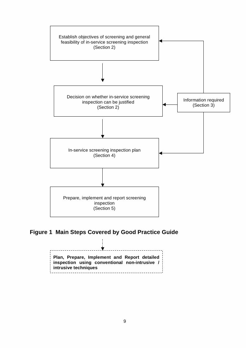
Screening inspections cover large volumes at high speed and identify areas of concern. Areas of concern identified by screening inspections are generally investigated in detail through the use of more sensitive conventional inspection techniques. This document provides guidance on the main steps illustrated in Figure 1 overleaf.
Note that the level of information required is likely to increase from the process of determining general feasibility through deciding whether in-service screening inspection can be justified, to detailed screening planning.
Many of the recommendations in this document are not unique to in-service screening inspection since proper planning and administration is also important for conventional inspection. The document should be considered in conjunction with other relevant guidelines such as those contained in the document for Non-Intrusive Inspections (Ref. 1) and HSE Best Practice for NDT document (Ref. 5).
The inspection management methodology should take into account the substantial increase in volumetric coverage achieved by screening.
9
Figure 1 Main Steps Covered by Good Practice Guide
Establish objectives of screening and general feasibility of in-service screening inspection
(Section 2)
Decision on whether in-service screening
inspection can be justified (Section 2)
In-service screening inspection plan
(Section 4)
Information required (Section 3)
Prepare, implement and report screening
inspection (Section 5)
Plan, Prepare, Implement and Report detailed inspection using conventional non-intrusive / intrusive techniques
10
2. BASIS FOR PERFORMING SCREENING
2.1 Objective of screening techniques
It is essential to be clear about the reasons for performing an in-service screening inspection. The objective of in-service screening inspection has to be determined in advance. This may have an impact on the approach to the screening inspection as well as followup detailed inspection.
The decision to carry out in-service screening inspection will normally depend on a number of different factors. A primary advantage is likely to be risk reduction at reasonable cost. For safety critical plant items, risk can be minimized by first interrogating preferably 100% volume using fast screening techniques (e.g. long range UT for pipes) and then conducting detailed inspections at the targeted locations using more sensitive techniques. For inspecting some inaccessible areas screening techniques may be the only solution.
Questions may include:
• Is the inspection to complement risk based inspection programme?
• Is the inspection intended to provide 100% volumetric coverage?
Potential benefits of using screening techniques include:
• Reduction of Risk: Many of the in-service screening techniques can provide fast coverage of large volume. Rather than use sampling for general trends, it is possible to obtain detailed qualitative and somewhat quantitative information about the condition of the plant.
• Inspection of inaccessible areas. Many applications, hitherto considered inaccessible, can be inspected using some of the screening techniques thus reducing unexpected failures and associated consequences including health and safety and environmental hazards and loss of production.
• Planning for shutdown. Carrying out in-service screening inspection followed by targeted detailed inspection before the shutdown commences, providing an opportunity for the shutdown to be shortened by long-lead time planning and preparation (for repair and maintenance based upon the NDT results) to be made in advance of the start of the shutdown.
• Shortening the shutdown. Many of the screening techniques can be deployed while plant is in operation. Most or all of the inspection work can be carried out in advance of the shutdown. Thus, shutdown duration may be reduced, being restricted to mechanical work. This also simplifies planning.
• Minimise manual activities: Many of the screening techniques require minimum preparation including insulation removal, surface preparation and scanning.
• Possible to carry out onstream screening in-service inspections.
11
2.2 Decision On Whether to Screen
Before deciding whether to perform a screening inspection, it must be established whether the required information can be obtained from the inspection.
The first step is to decide if it is feasible to carry out screening inspection. This is based on an initial consideration of the access to the external surface, geometry, materials, presence of cladding or insulation, requirement for inspection of internal fittings, expected or postulated degradation.
The next step is to decide whether sufficient information exists to plan the screening inspection and what inspection effectiveness is required. This requires consideration of how confidently potential defect types and locations can be predicted, the effectiveness of previous inspections, and the severity and rate of any known or predicted degradation.
The third stage is to determine whether screening inspection techniques can provide the inspection effectiveness required, taking into account aspects such as geometry, surface coating / insulation, temperature and available access. At this stage, it may become evident that the required assurance of integrity cannot be achieved by screening inspection and it may be necessary to perform conventional NDT.
Reference 1 provides guidance on determining whether Non-Invasive inspection is appropriate for a particular plant equipment.
It is important to recognise that implementing a screening inspection strategy is likely to require a step-change in the administration and execution of inspection.
• Screening inspection techniques are likely to be less sensitive and much faster compared to conventional non-invasive inspection.
• Planning of the inspection needs to be thorough (see Section 4). Screening inspection generally has to be followed by targeted more sensitive non-invasive inspection.
• The screening inspection must be controlled rigorously, with the procedures carefully scrutinised and controlled. Equipment, settings and reporting criteria must be carefully set.
• Known areas of degradation should be identified and quantified to the NDT operator in advance of the inspection. (Change in the extent of degradation may be as important as new areas of degradation)
• The reporting format must be precisely specified. If the results are not requested in the correct form at the outset of the inspection or are inadequately reported, it can be difficult to transform the data to the correct format. Useful information may be overlooked or lost.
12
3. INFORMATION REQUIRED TO SELECT A PARTICULAR SCREENING TECHNIQUE
3.1 General Approach
The choice of technique for conducting screening inspection can depend critically on the type of defect or degradation mechanism to be detected and sensitivity required. Screening inspection techniques vary significantly in the speed of applicaton. Some techniques are more suitable for 100% inspection of plant whereas others can be applied quickly for detection of defects in most probable locations. This means that selection of a suitable screening technique for inspection requires careful consideration of the plant to be inspected, the defects/degradation to be detected. The inspection needs to take into consideration strengths and limitations of the technique being applied.
The available access to the component is another consideration with some techniques being more tolerant to restrictions than others. Several techniques have the ability to screen for corrosion under insulation.
Planning a screening inspection must be carried out in a systematic manner. Certain information about the application is required in advance.
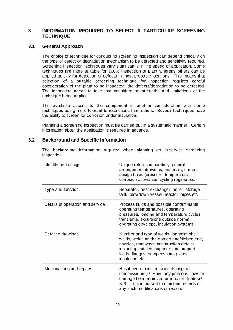
3.2 Background and Specific Information
The background information required when planning an in-service screening inspection.
Identity and design Unique reference number, general arrangement drawings, materials, current design basis (pressure, temperature, corrosion allowance, cycling regime etc.)
Type and function. Separator, heat exchanger, boiler, storage tank, blowdown vessel, reactor, pipes etc
Details of operation and service. Process fluids and possible contaminants, operating temperatures, operating pressures, loading and temperature cycles, transients, excursions outside normal operating envelope, insulation systems.
Detailed drawings Number and type of welds, long/circ shell welds, welds on the domed end/dished end, nozzles, manways, construction details including saddles, supports and support skirts, flanges, compensating plates, insulation etc.
Modifications and repairs Has it been modified since its original commissioning? Have any previous flaws or damage been removed or repaired (dates)? N.B. – it is important to maintain records of any such modifications or repairs.
13
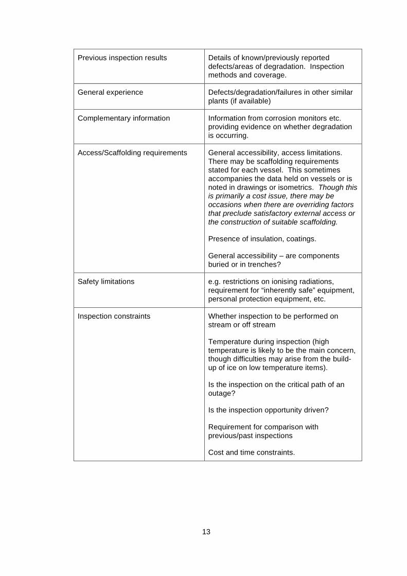
Previous inspection results Details of known/previously reported defects/areas of degradation. Inspection methods and coverage.
General experience Defects/degradation/failures in other similar plants (if available)
Complementary information Information from corrosion monitors etc. providing evidence on whether degradation is occurring.
Access/Scaffolding requirements General accessibility, access limitations. There may be scaffolding requirements stated for each vessel. This sometimes accompanies the data held on vessels or is noted in drawings or isometrics. Though this is primarily a cost issue, there may be occasions when there are overriding factors that preclude satisfactory external access or the construction of suitable scaffolding.
Presence of insulation, coatings.
General accessibility – are components buried or in trenches?
Safety limitations e.g. restrictions on ionising radiations, requirement for “inherently safe” equipment, personal protection equipment, etc.
Inspection constraints Whether inspection to be performed on stream or off stream
Temperature during inspection (high temperature is likely to be the main concern, though difficulties may arise from the build-up of ice on low temperature items).
Is the inspection on the critical path of an outage?
Is the inspection opportunity driven?
Requirement for comparison with previous/past inspections
Cost and time constraints.
14
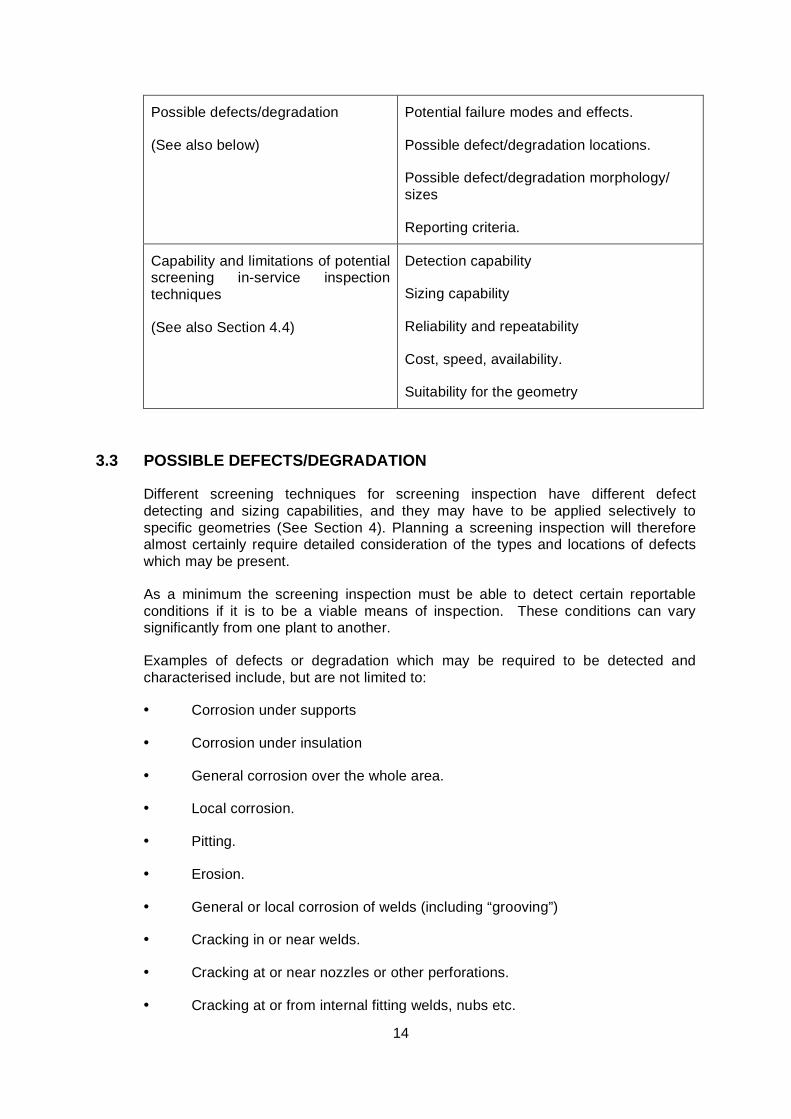
Possible defects/degradation
(See also below)
Potential failure modes and effects.
Possible defect/degradation locations.
Possible defect/degradation morphology/ sizes
Reporting criteria.
Capability and limitations of potential screening in-service inspection techniques
(See also Section 4.4)
Detection capability
Sizing capability
Reliability and repeatability
Cost, speed, availability.
Suitability for the geometry
3.3 POSSIBLE DEFECTS/DEGRADATION
Different screening techniques for screening inspection have different defect detecting and sizing capabilities, and they may have to be applied selectively to specific geometries (See Section 4). Planning a screening inspection will therefore almost certainly require detailed consideration of the types and locations of defects which may be present.
As a minimum the screening inspection must be able to detect certain reportable conditions if it is to be a viable means of inspection. These conditions can vary significantly from one plant to another.
Examples of defects or degradation which may be required to be detected and characterised include, but are not limited to:
• Corrosion under supports
• Corrosion under insulation
• General corrosion over the whole area.
• Local corrosion.
• Pitting.
• Erosion.
• General or local corrosion of welds (including “grooving”)
• Cracking in or near welds.
• Cracking at or near nozzles or other perforations.
• Cracking at or from internal fitting welds, nubs etc.
15
• Stress corrosion cracking in parent material
• Hydrogen damage (e.g. blistering, stepwise cracking).
It is important to consider the different and possibly unusual defect morphologies which can occur (e.g. microbiological induced corrosion) since these aspects can influence the selection and capability of screening inspection techniques.
4. SCREENING INSPECTION PLAN
4.1 General Approach
The inspection plan for a screening inspection involves the definition of the items to be inspected, the types of degradation or defects to be detected and characterised, and the screening technique. Screening inspection will normally be carried out for 100% coverage (some techniques provide 100% volumetric coverage while some other techniques are best suited for 100% linear coverage along the length of the pipe). There should be a prescribed path for consultation and decision-making for establishing the strategy and plan for follows inspection.
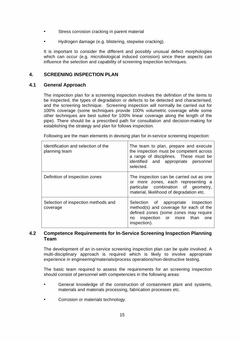
Following are the main elements in devising plan for in-service screening inspection:
Identification and selection of the planning team
The team to plan, prepare and execute the inspection must be competent across a range of disciplines. These must be identified and appropriate personnel selected.
Definition of inspection zones The inspection can be carried out as one or more zones, each representing a particular combination of geometry, material, likelihood of degradation etc.
Selection of inspection methods and coverage
Selection of appropriate inspection method(s) and coverage for each of the defined zones (some zones may require no inspection or more than one inspection).
4.2 Competence Requirements for In-Service Screening Inspection Planning Team
The development of an in-service screening inspection plan can be quite involved. A multi-disciplinary approach is required which is likely to involve appropriate experience in engineering/materials/process operations/non-destructive testing.
The basic team required to assess the requirements for an screening inspection should consist of personnel with competencies in the following areas:
• General knowledge of the construction of containment plant and systems, materials and materials processing, fabrication processes etc.
• Corrosion or materials technology.
16
• Specific knowledge of the systems to be inspected, operational history and ‘general knowledge’, (knowledge of the working practices and history of the system, safety requirements, and the likely conditions at the time of inspection).
• Non-destructive testing.
• Nominated person to coordinate the overall process.
Team members may have more than one of the specified skills; it is not necessary for the team to contain individual specialists in all of the above.
The most effective team is likely to be the smallest team that has the requisite skills, but the team should not be reduced excessively, as items are likely to be overlooked. Personnel to carry out any of these functions should be competent to assess their own level of expertise in the selected area. One member of the team should take responsibility for the overall planning process.
The inspection strategy should also specify the minimum requirements for those who will perform the inspection.
4.3 Definition of Inspection Zones
In-service screening inspection techniques have different capabilities and limitations for different degradation and defect types and can be heavily influenced by aspects such as geometry and material. It is generally impractical to perform one type of in-service screening inspection over the entire range of equipments in a plant.
The inspection of a plant should therefore be segregated into zones, each zone representing particular combinations of geometries, materials, likelihood of degradation, possible degradation mechanisms and previous inspection history (The concept of segregating plant into zones is coherent with similar concept in Ref. 1). This then provides the basis for deciding which zones of the plant should be inspected, by which methods. Wider coverage (upto 100 % volumetric) provided by in-service screening inspections provides much more information on the condition of the plant than sampling / localized area inspections.
Examples of features which could be considered when dividing the plant into zones include:
• Insulated Piping
• Buried / Embedded Piping
• Piping supports / Hangers
• Vessels
• Insulated Vessels
• Longitudinal welds.
• Circumferential welds.
• Attachment welds.
17
• Nozzle welds.
• Parent material with little probability of corrosion/erosion.
• Parent material with medium probability of corrosion/erosion.
• Parent material with the highest probability of corrosion/erosion
• Known corroded area in parent material.
Note that these are examples only: The zones should be determined by considering the detailed design, function, operating conditions and history of the plant. The underlying principle is that each individual zone should be “homogeneous” so that any given segment of a zone is representative of the rest of that zone in terms of likelihood of degradation, type of possible degradation, tolerance to degradation and type of screening inspection method(s) which can be applied. Suitable inspection method and the basis for sensitivity can then be determined individually for each zone. Zones which are physically separate but similar can be considered as one, for the purpose of inspection planning.
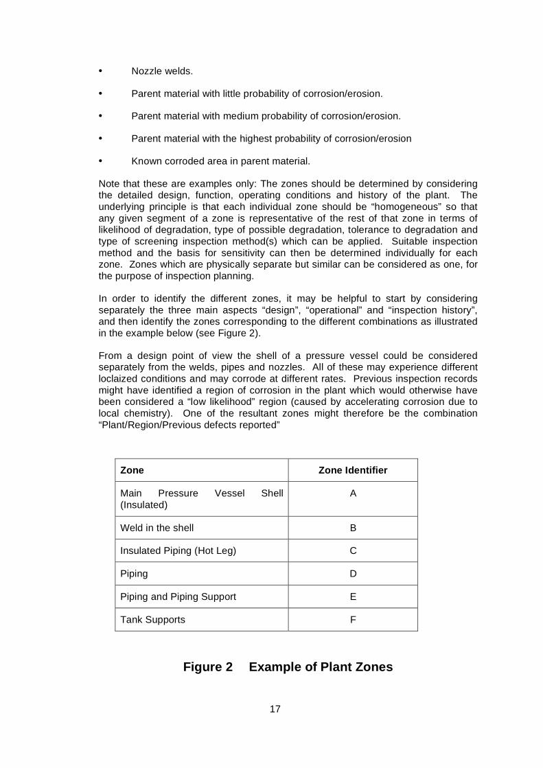
In order to identify the different zones, it may be helpful to start by considering separately the three main aspects “design”, “operational” and “inspection history”, and then identify the zones corresponding to the different combinations as illustrated in the example below (see Figure 2).
From a design point of view the shell of a pressure vessel could be considered separately from the welds, pipes and nozzles. All of these may experience different loclaized conditions and may corrode at different rates. Previous inspection records might have identified a region of corrosion in the plant which would otherwise have been considered a “low likelihood” region (caused by accelerating corrosion due to local chemistry). One of the resultant zones might therefore be the combination “Plant/Region/Previous defects reported”
Zone Zone Identifier
Main Pressure Vessel Shell (Insulated)
A
Weld in the shell B
Insulated Piping (Hot Leg) C
Piping D
Piping and Piping Support E
Tank Supports F
Figure 2 Example of Plant Zones
18
When considering the zones corresponding to operational conditions, consideration should be given to previous experience from that plant, experience from similar types of plants operating under broadly similar conditions, and generic knowledge and experience of how the material behaves under the particular operating conditions (process, temperature, etc.).
Note that further subdivisions of zones may be necessary, e.g. regions with limited access to inspection surface due to obstructions.
4.4 Selection of Inspection Methods and Coverage
4.4.1 Introduction
Having identified the different zones within the plant, the inspection effectiveness required should be determined on a zone by zone basis. The level of effectiveness which is appropriate for a particular zone will depend on the likelihood of degradation, previous inspection results, tolerance to degradation, and the consequence of failure.
Some zones may require no inspection. Some may require 100% screening inspection or 100% inspection using highly sensitive, though slow, techniques. Others zones may require only spot checks or sample inspections using conventional non-intrusive inspection methods,.
4.4.2 Inspection Methods and Techniques
A general description of the main methods and techniques available for in-service screening inspection of plant is provided in Appendix 1. More detailed information is provided in Appendix 2.
Although commercially available screening techniques and generic procedures may be appropriate for some zones (e.g. Ultrasonic guided wave inspection for piping and insulated pipes, corrosion under insulation by Lixi Profiler) in other instances it may be necessary to apply specialised screening inspection techniques (e.g. where access to inspection surfaces is restricted; where complicated defect orientations/morphologies are sought; difficult material or geometry).
Planning of the screening inspection should take account of any pre-inspection development work and personnel training and qualification requirements where specialised techniques not covered by the general certification schemes (e.g. Refs. 1-3) are to be applied.
Clearly there is a need for continuity between inspections and the introduction of a radically different inspection technique may complicate the comparison of results (particularly when changing from a non-invasive inspection regime to screening followed by targeted detailed inspection). Therefore new procedures and techniques must take account of the reporting criteria and format of previously applied inspections.
19
4.4.3 Inspection Requirement For Each Zone
The inspection effectiveness required is likely to be different for different zones, depending on e.g. the design, likelihood of degradation and previous inspection results for each zone.
If for a particular zone the design is such that tolerance to defects is high, the likelihood of degradation is very low, and previous inspections have not detected any degradation, then there may be a strong justification for performing only minimal inspection (or no inspection) of that zone.
In this context tolerance to defects can be considered in terms of the likelihood that any known or predicted degradation would cause failure of the plant within its remaining lifetime (see Appendix 3).
If on the other hand defect tolerance is low and the likelihood of degradation is high, there is obviously an incentive to do a much more comprehensive inspection in that particular zone.
The inspection requirements should therefore be determined on a zone by zone basis. The overall objective should be to ensure that the integrity of each zone meets the minimum level needed to ensure the continued integrity required for the plant as a whole.
For each zone consideration should be given to the factors which will influence the level of inspection required such as tolerance to defects, likelihood of defects and previous inspection results. This will help to establish a ranking of zones in terms of the level of inspection required.
The consequences of plant failure must be considered when determining what level of inspection is appropriate for each order of ranking. For example two equipments, might have similar zones and the zones might have similar rankings in terms of which were to be subject to the most rigorous inspections etc. However the inspection effectiveness corresponding to “most rigorous” might be different between the two equipments if the consequences of equipment / plant failure were different.
Reference 5 provides an insight into how screening inspection reduces the risk of failure, where risk of failure is a combination of likelihood of failure and consequence of failure. Inspection can only reduce likelihood of failure, not consequence. For a plant where consequence of failure is high, inspection should have the potential to maintain likelihood of failure at a low level. If the predicted likelihood of failure (without inspection) is high, then there needs to be high confidence in the capability and reliability of the inspection method to detect (and correctly sentence) defects or degradation of concern. More detailed guidance on effectiveness of screening techniques is provided in Appendix 2.
Effectiveness of screening inspection will depend on the inherent capability of the inspection methods used, their reliability under real site conditions, the inspection coverage (whether 100% of a zone) and the competence of those performing and analysing the inspection results.
More detailed guidance on inspection planning is provided in Appendix 3.
20
5 INSPECTION PREPARATION, IMPLEMENTATION AND REPORTING
All the guidelines on inspection preparation, implementation and reporting are generic in nature. The guidelines in this section are coherent with Ref. 1.
5.1 Preparation of Workpack
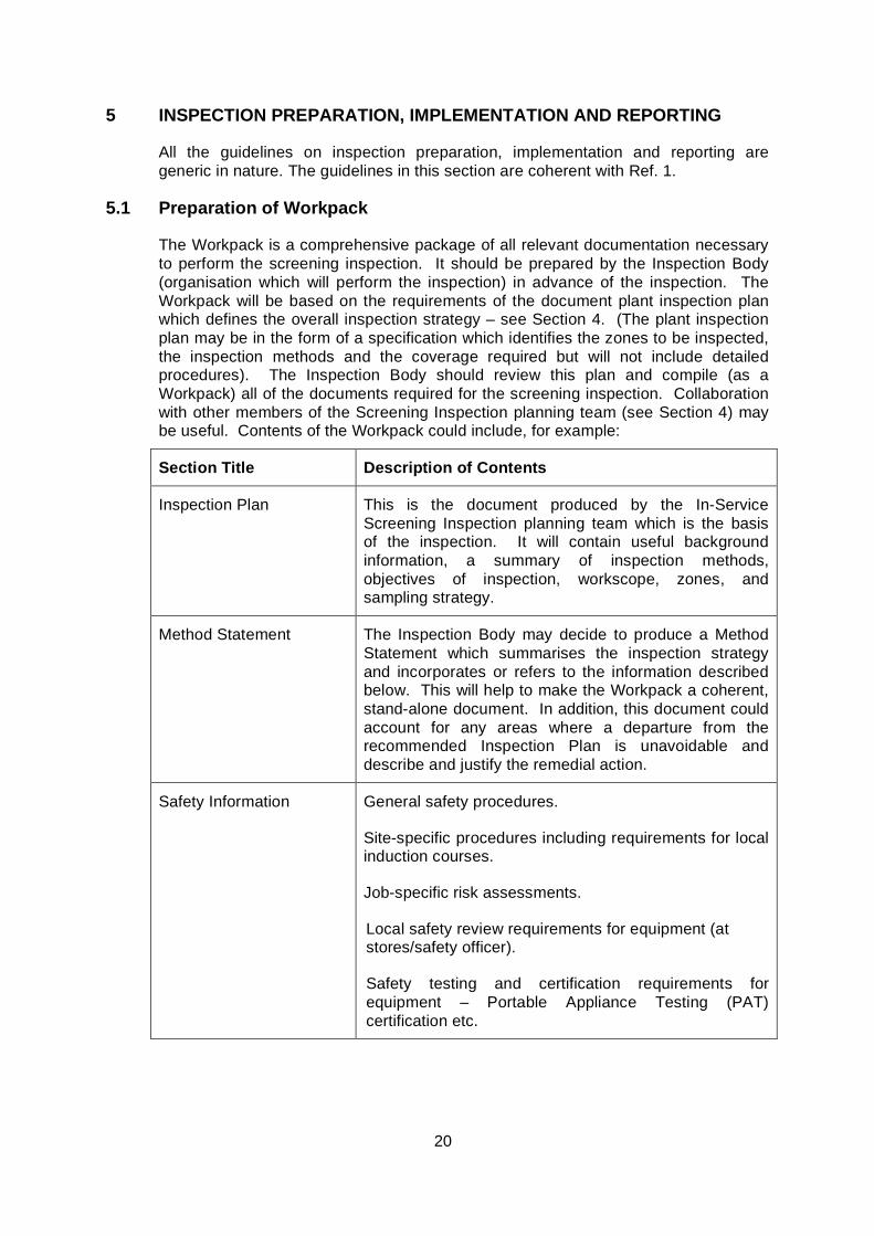
The Workpack is a comprehensive package of all relevant documentation necessary to perform the screening inspection. It should be prepared by the Inspection Body (organisation which will perform the inspection) in advance of the inspection. The Workpack will be based on the requirements of the document plant inspection plan which defines the overall inspection strategy – see Section 4. (The plant inspection plan may be in the form of a specification which identifies the zones to be inspected, the inspection methods and the coverage required but will not include detailed procedures). The Inspection Body should review this plan and compile (as a Workpack) all of the documents required for the screening inspection. Collaboration with other members of the Screening Inspection planning team (see Section 4) may be useful. Contents of the Workpack could include, for example:
Section Title Description of Contents
Inspection Plan This is the document produced by the In-Service Screening Inspection planning team which is the basis of the inspection. It will contain useful background information, a summary of inspection methods, objectives of inspection, workscope, zones, and sampling strategy.
Method Statement The Inspection Body may decide to produce a Method Statement which summarises the inspection strategy and incorporates or refers to the information described below. This will help to make the Workpack a coherent, stand-alone document. In addition, this document could account for any areas where a departure from the recommended Inspection Plan is unavoidable and describe and justify the remedial action.
Safety Information General safety procedures.
Site-specific procedures including requirements for local induction courses.
Job-specific risk assessments.
Local safety review requirements for equipment (at stores/safety officer).
Safety testing and certification requirements for equipment – Portable Appliance Testing (PAT) certification etc.
21
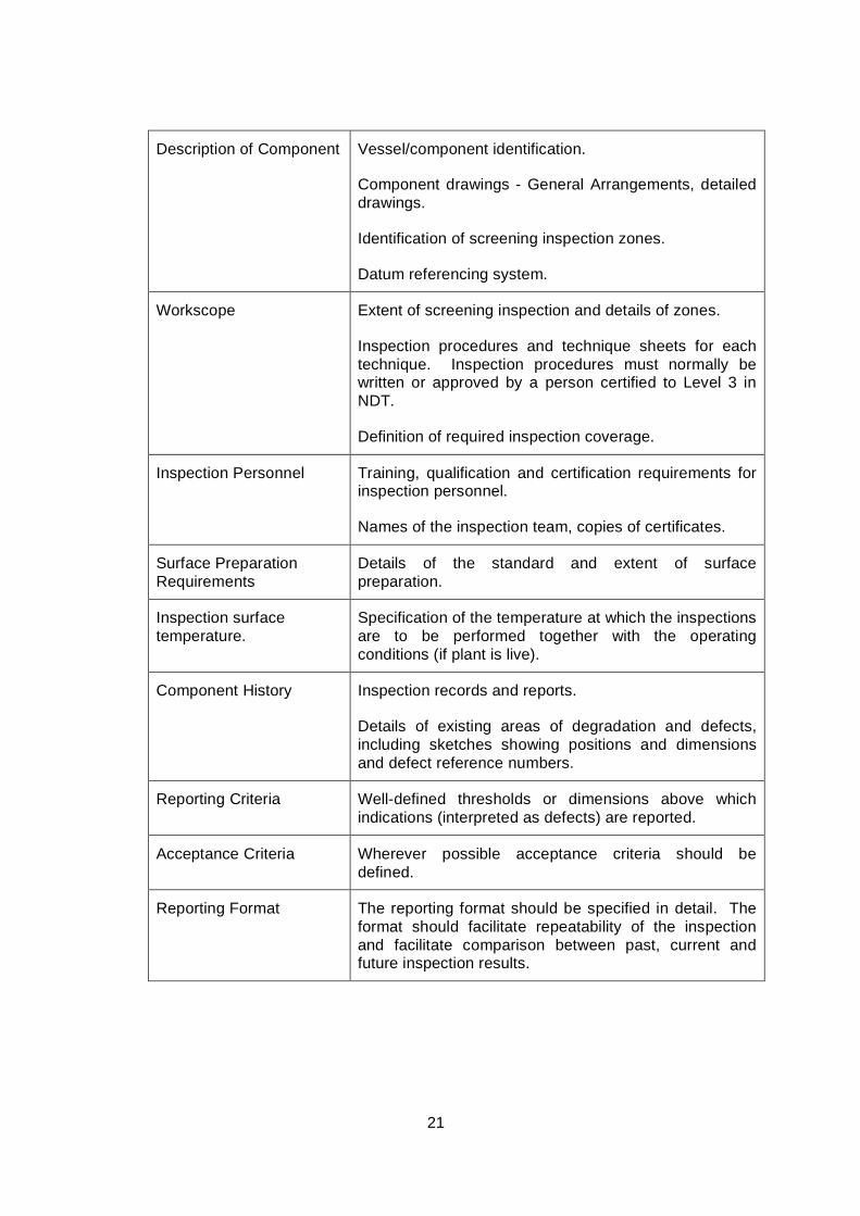
Description of Component Vessel/component identification.
Component drawings - General Arrangements, detailed drawings.
Identification of screening inspection zones.
Datum referencing system.
Workscope Extent of screening inspection and details of zones.
Inspection procedures and technique sheets for each technique. Inspection procedures must normally be written or approved by a person certified to Level 3 in NDT.
Definition of required inspection coverage.
Inspection Personnel Training, qualification and certification requirements for inspection personnel.
Names of the inspection team, copies of certificates.
Surface Preparation Requirements
Details of the standard and extent of surface preparation.
Inspection surface temperature.
Specification of the temperature at which the inspections are to be performed together with the operating conditions (if plant is live).
Component History Inspection records and reports.
Details of existing areas of degradation and defects, including sketches showing positions and dimensions and defect reference numbers.
Reporting Criteria Well-defined thresholds or dimensions above which indications (interpreted as defects) are reported.
Acceptance Criteria Wherever possible acceptance criteria should be defined.
Reporting Format The reporting format should be specified in detail. The format should facilitate repeatability of the inspection and facilitate comparison between past, current and future inspection results.

22
Programme An outline of the inspection programme to enable the detailed planning of resources.
Advice on any parallel activities which may impact on the timing or performance of the inspection.
Results Documents which evolve as the inspection progresses (e.g. inspection reports) should be added to the Workpack.
Once prepared, the Workpack should be formally issued and treated as a controlled document. Relevant documents which are produced during the course of the inspection, e.g. inspection reports, should be incorporated in the Workpack, with copies sent to all those issued with controlled copies of the Workpack. When completed, the workpack and results, together with the analysis should become part of the plant inspection history records.
The master Workpack should be issued to the Inspection Manager who will assume responsibility for maintaining it. The Workpack should be issued in advance of the inspection to allow adequate time for inspection preparation.
5.2 PREPARATION FOR INSPECTION
Preparation for the inspection will require contributions from each of the following members of the inspection team:
Role Responsibilities
Inspection Manager
(the plant owner’s representative)
To ensure that all of the parties are aware of what is expected of them, and have access to all of the relevant information. To process and act upon any feedback on the inspection Workpack.
Inspection Supervisor
(the leader of the site NDT Team)
This is the key coordinating role. The Inspection Supervisor has many critical responsibilities and there may be a need for more than one supervisor for large scale inspections (or at least for the Inspection Supervisor to delegate some of the tasks to other team members). The Inspection Supervisor should liase between all parties and ensure good communication.
The Inspection Supervisor should be certified at least to EN473 Level 2 in the methods of NDT to be applied during the inspection. However, Level 3 certification is preferable, particularly when the Inspection Supervisor is not participating directly in the execution of the inspections.
23
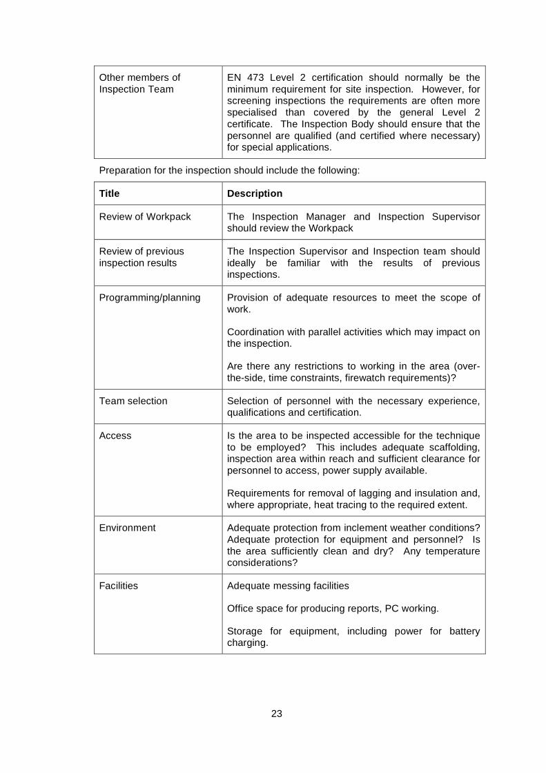
Other members of Inspection Team
EN 473 Level 2 certification should normally be the minimum requirement for site inspection. However, for screening inspections the requirements are often more specialised than covered by the general Level 2 certificate. The Inspection Body should ensure that the personnel are qualified (and certified where necessary) for special applications.
Preparation for the inspection should include the following:
Title Description
Review of Workpack The Inspection Manager and Inspection Supervisor should review the Workpack
Review of previous inspection results
The Inspection Supervisor and Inspection team should ideally be familiar with the results of previous inspections.
Programming/planning Provision of adequate resources to meet the scope of work.
Coordination with parallel activities which may impact on the inspection.
Are there any restrictions to working in the area (over-the-side, time constraints, firewatch requirements)?
Team selection Selection of personnel with the necessary experience, qualifications and certification.
Access Is the area to be inspected accessible for the technique to be employed? This includes adequate scaffolding, inspection area within reach and sufficient clearance for personnel to access, power supply available.
Requirements for removal of lagging and insulation and, where appropriate, heat tracing to the required extent.
Environment Adequate protection from inclement weather conditions? Adequate protection for equipment and personnel? Is the area sufficiently clean and dry? Any temperature considerations?
Facilities Adequate messing facilities
Office space for producing reports, PC working.
Storage for equipment, including power for battery charging.
24
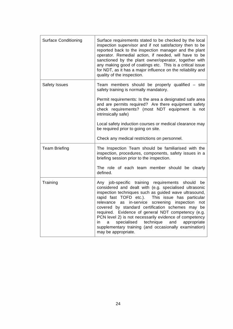
Surface Conditioning Surface requirements stated to be checked by the local inspection supervisor and if not satisfactory then to be reported back to the inspection manager and the plant operator. Remedial action, if needed, will have to be sanctioned by the plant owner/operator, together with any making good of coatings etc. This is a critical issue for NDT, as it has a major influence on the reliability and quality of the inspection.
Safety Issues Team members should be properly qualified – site safety training is normally mandatory.
Permit requirements: Is the area a designated safe area and are permits required? Are there equipment safety check requirements? (most NDT equipment is not intrinsically safe)
Local safety induction courses or medical clearance may be required prior to going on site.
Check any medical restrictions on personnel.
Team Briefing The Inspection Team should be familiarised with the inspection, procedures, components, safety issues in a briefing session prior to the inspection.
The role of each team member should be clearly defined.
Training Any job-specific training requirements should be considered and dealt with (e.g. specialised ultrasonic inspection techniques such as guided wave ultrasound, rapid fast TOFD etc.). This issue has particular relevance as in-service screening inspection not covered by standard certification schemes may be required. Evidence of general NDT competency (e.g. PCN level 2) is not necessarily evidence of competency in a specialised technique and appropriate supplementary training (and occasionally examination) may be appropriate.

25
Mobilisation Equipment should be checked in advance of shipping to the inspection site. Mobilisation to site/platform may require advance shipping of the equipment. It may be advisable to prepare a checklist of ancillary items that may be needed (tools, reporting materials, markers, spare consumables/IT consumables), check that the requisite software is installed on computers.
The team should ensure that the requirements for the equipment have been met (including calibration and certification) and that everything is in good condition, batteries charged, PAT certification satisfactory etc. before packing and shipping or mobilisation.
Start-up Meeting All parties should meet prior to the inspection to ensure lines of communication are clear and all understand the inspection requirements and objectives.
5.3 Performing the Inspection
The Inspection Manager (or an appropriate senior delegate) should coordinate the Permit To Work system and liase with site personnel and the inspection team.
The Inspection Manager should monitor progress against the programme and take appropriate action where necessary.
The NDT operators should comply with the agreed scope of work, and inform the supervisor of any obstructions or anomalous measurements at the earliest opportunity.
The Inspection team should practice good housekeeping both during the course of the inspections and on completion of the inspection.
5.4 Reporting of Results
The format for reporting results of screening inspection will have been specified by the Inspection Management Team and defined in the Workpack.
Guidance is provided below.
Reporting Criteria and Format
The reporting criteria and format should be specified in detail. The format should facilitate repeatability of the inspection and comparison between past, current and future inspection results.
Proforma reporting formats are recommended to optimise repeatability. These should prompt the operator to enter the same type of information recommended for any routine NDT inspection.
Generally the following information should be included in the report:
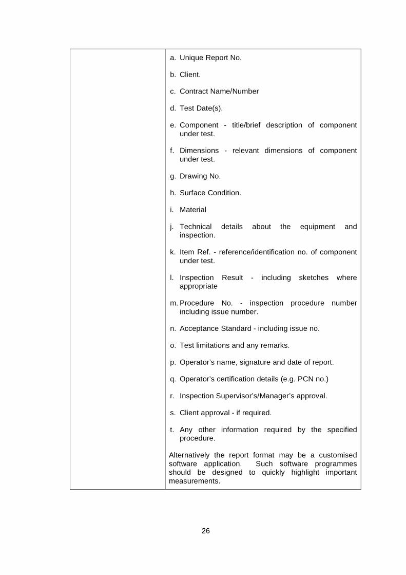
26
a. Unique Report No.
b. Client.
c. Contract Name/Number
d. Test Date(s).
e. Component - title/brief description of component under test.
f. Dimensions - relevant dimensions of component under test.
g. Drawing No.
h. Surface Condition.
i. Material
j. Technical details about the equipment and inspection.
k. Item Ref. - reference/identification no. of component under test.
l. Inspection Result - including sketches where appropriate
m. Procedure No. - inspection procedure number including issue number.
n. Acceptance Standard - including issue no.
o. Test limitations and any remarks.
p. Operator’s name, signature and date of report.
q. Operator’s certification details (e.g. PCN no.)
r. Inspection Supervisor’s/Manager’s approval.
s. Client approval - if required.
t. Any other information required by the specified procedure.
Alternatively the report format may be a customised software application. Such software programmes should be designed to quickly highlight important measurements.

27
The Inspection Supervisor should check the screening inspection reports and the Inspection Manager should evaluate the results as early as possible. This will ensure early warning of any of the following situations and allow more time to take the necessary action:
• Any new significant defects
• Any significant changes in the inspection result
• Any factor which has restricted the screening inspection
• Restrictions to the performance of the inspection in accordance with the procedure
• Incorrect application of the procedure
• The need for followup detailed inspections
The screening inspection reports should be reviewed and approved by the Inspection Supervisor and Manager. The approved reports should be incorporated in the Workpack.
The Workpack shall be archived and available for review prior to and during the next inspection.
5.5 DEMOBILISATION
The Inspection Supervisor should check that all parties are aware of and satisfied with the completion of the screening inspection.
The equipment should be checked before packing and shipping.
A debriefing meeting with all parties is recommended. This offers opportunity for feedback, lessons learned, recommendations for future inspections.
6. REFERENCES
1. Document For Non-Invasive Inspections To be published by DNV – document produced by ESR Technology, in collaboration with Doosan Babcock, through the HOIS programme
2. PCN/GEN General Requirements for Qualification and PCN Certification of NDT Personnel. British Institute of Non-Destructive Testing
3. EN 473 General Principles for Qualification and Certification of NDT personnel
4. ISO 9712 Non-destructive testing - Qualification and certification of personnel
5. Best Practice For The Procurement And Conduct Of Non-Destructive Testing. Part I: Manual Ultrasonic Inspection

28
HSE Gas And Process Safety Technology Division, November 2000. www.hse.gov.uk/dst/ndt.pdf
6. Decision Guidance Process for Non-Invasive Inspection : User Guide. Produced for HOIS 2000 by AEA Technology.
7. Introduction to Life Prediction of Industrial Materials:Application of the Extreme Value Method for Corrosion Analysis M. Kowaka, Allerton Press 1994
8. Probabilistic Models for Optimising Defect Detection in LPG Welds G. A. Georgiou, Proceedings of the British Institute of NDT Conference 2000, pp 168 - 173

29
APPENDIX 1
REVIEW OF SCREENING TECHNIQUES FOR IN-SERVICE INSPECTION
30
1. INTRODUCTION
This review gives a brief description of the principles, capabilities and limitations of NDT methods which might be considered as screening techniques for inservice inspection, including:
1. Guided Ultrasonic Wave (Teletest, Wavemaker and Magnetostrictive Sensors)
2. CHIME 3. M-SKIP 4. LORUS 5. EMAT 6. Verkade 7. TOFD Fast Screening 8. Rapidscan 9. Acoustic Emission 10. Quantitative Acoustic Emission 11. Lixi 12. SCAR 13. Thruvu 14. Neutron Backscatter 15. SLOFEC 16. Pulsed Eddy current (PEC and Incotest) 17. Magnetic Flux Leakage (MFL and MFL Pipescan) 18. Microwave 19. Thermography 20. Laser Shearography
2. ULTRASONIC TECHNIQUES
2.1 Ultrasonic Guided Wave (Teletest) Technique
Long Range Guided Wave Ultrasonics potentially allows a large volume of pipework to be inspected from a single transducer position.
An array of piezoelectric transducers is clamped around the pipe and an ultrasound signal is sent in both directions along the pipe allowing for 100% volumetric screening of the pipe wall.
Ultrasonic transducers send a symmetrical wave of ultrasound energy axially along the length of the pipe, features generate a series of reflections of this sound which are detected at the tool. A feature with a symmetrical change in wall thickness such as a weld generates a symmetrical reflected signal, whereas a localised thickness change causes a flexural signal to be returned which is recorded differently.
The best application of the technique is on above-ground long, relatively featureless, un-flanged lengths of pipe for rapid inspection of both internal and external corrosion.
Guided waves systems can typically detect most metal loss and cracks > 5% cross-sectional area depending on given conditions.
31
In general, a range of 60m (30m in each direction) is a reasonable expectation.
Guided waves are suitable for use on ASME schedule pipe diameters from 38 mm (1.5”) to 1200 mm (48”). Equipment for other pipe sizes is available on request. Wall thicknesses up to 80mm (1.6”) have been inspected.
High viscosity of the pipe content (for example hydrocarbons) will attenuate the signal and can therefore be difficult to inspect. Pipes coated with certain coatings can be hard to inspect. Coating condition and bond nature affect the ease of inspection, both of which can change after operational application.
Secondary inspection should be carried out using alternative techniques such as radiography or conventional UT for full quantitive evaluation of potential corrosion areas.
2.2 Ultrasonic Guided Wave (Wavemaker) Technique
The basic principle of operations of wavemaker is similar to that of wavemake described in 2.1 above. A unit of piezoelectric transducers is clamped around the pipe and the GW are sent simultaneously in both directions along the pipe with 100% screening coverage within its diagnostic length.
Wavemaker technology is available both in screening and monitoring configuration (PIMS). Wavemaker G3 in screening configuration can detect metal loss and cracks > 1% cross-sectional area depending under ideal conditions. From 5% cross sectional area most defects can according to the suppliers be detected with confidence. Under ideal conditions Wavemaker G3 in monitoring configuration can detect defects as small as 0.1% of the cross sectional area.
Wavemaker technology is available both with external or internal access transduction system. T-scan (internal access system) is used to screen structures such as heat exchanger tubes.
Wavemaker technology is also used for underwater inspection of risers and other pipelines.
Wavemaker system is suitable for use on pipe diameters from 16mm (3/4”) - 1800 mm (72”). Inflatable rings need to be used for bigger pipes. Wall thicknesses up to 75mm (3”) have been inspected.
Pipes coated with attenuative coatings (e.g. soft thick and well adhered bitumen) can reduce range (or sensitivity). Coating condition and bond nature affect the ease of inspection, both of which can change after operational application.
Under ideal conditions roughly 100m can be inspected in a single test. The length of pipe that can be inspected is heavily dependant on several factors and range can be much lower than ideal case.
2.3 Guided Ultrasonic Wave (Magnetostrictive Sensors) Technique
Magnetostrictive transducer generates non-dispersive mode of ultrasound energy and transmits it into the material under investigation. A symmetrical change in wall
32
thickness generates a uniformly reflected signal whereby a localised thickness change is recorded differently.
A magnetostrictive strip is bonded around the pipe and an energizing coil is wrapped over it. Ultrasound is sent in the desired direction along the pipe with 100% screening coverage. The sensor is very light and weighs only 1 Kg for 24” diameter pipe.
MsS is suitable for monitoring condition and rapid inspection of long, un-flanged lengths of pipe and detection of both internal and external corrosion.
MsS can detect defects > 2 – 5% cross-sectional area depending on given conditions. Defects > 10% cross sectional area can, according to the suppliers’ brochure, be detected in buried or long pipes. In condition monitoring mode defects > 1% cross-sectional area can be detected.
Suitable for use on pipe diameters 0.75” to 60”.
Under ideal conditions roughly 150m can be inspected per reading. The length of pipe that can be inspected is heavily dependant on several factors
MsS system has specially designed probes for inspection of plates, cables and heatexchanger tubes.
Pipes coated with certain coatings can be hard to inspect. Coating condition and pressure affect the ease of inspection.
Curing of adhesive used for bonding strips to pipe takes 2 hours before test can be carried out. Repeatability of the inspection can be jeopardised if measurements are taken before complete curing of the adhesive of the sensor strip are carried out.
2.4 CHIME
CHIME (Creeping / Head wave Inspection Method) provides total saturation of the material under inspection between two probes (one transmitter, one receiver). The CHIME probe shoes are angled which results in filling the volume of the component with 3 wave modes. Changes in the amplitude and arrival time of received signals indicate the presence of a defect in the material. The signals are usually imaged in shades of grey, dependent on signal amplitude.
It is a rapid, medium range, ultrasonic screening technique for use on vessels, pipes and plates. Main application is the detection of corrosion in pipes under supports, but can be used for other restricted access situations (e.g. corrosion under nozzle reinforcement plates). The technique can detect corrosion emanating from inner and outer surfaces but cannot distinguish between the two conditions.
CHIME is suitable for pipes >75mm diameter for circumferential beams. For axial beams, there is no restriction on diameter. For axial beams, the distance between the transmitting and receiving probes should be less than about 1m. For circumferential beams, the circumferential distance between probes should be less than about 700mm. Suitable for thicknesses in the range 3 – 50mm.
33
CHIME is semi-quantitative technique. Changes in transmission signal indicate the presence of a defect. Total signal loss indicates large defects. The amount of signal loss is related to the volume of the defect.
Only suitable for parallel or near-parallel walled material. Signals break up when wall thickness changes by 1mm over 75mm (13%).
2.5 LORUS
LORUS applies high sensitivity angle beam transducers in combination with an ultrasonic data recording system. The ultrasonic wave travels over multiple skips into the hard-to-access region. The presence of corrosion is established in the pulse-echo reflection mode. Reflection signals can be recorded together with 3-axis position encoder information. Coherent projection maps are calculated, showing directly location and extent of corrosion in one-to-one images.
LORUS has been developed for fast screening of hard-to-access locations, such as detection of corrosion in a storage tank’s annular plate from the outside of the tank. From a single access point, a large region may be inspected without direct access to the surface. Corrosion detection is achieved over a considerable distance (typically up to 1 meter). Compact manual scanners are applied in case of limited access and mechanized scanners are applied where possible for high inspection speed.
The technique is suitable for any tank diameter, annular plates from 6 to 25mm thick.
It can detect severe (pitting) corrosion, local gradual corrosion and can be used for corrosion growth monitoring however, it cannot discrimination between top and reverse side corrosion.
The scanning surface must be free of impurities, welding slag, surface corrosion and coatings, unless the coating is well bonded. Poor annular ring condition may affect the inspection range.
2.6 EMAT
The EMAT is an ultrasonic transducer, which operates without the application of liquid couplant. The EMAT transducer generates the ultrasound in the material being tested. As with piezo-electric transducers, different modes of ultrasound can be generated in the material to be tested by varying the design of the EMAT transducer. A further advantage of this type of transducer is that it can be designed to operate at elevated temperatures.
The EMAT testing equipment is normally housed in a trailer, which is located within a few hundred feet from the test location. The instrumentation consists of a pulser receiver unit with a computer to monitor the inspection. The test signal is displayed on a computer monitor. The output signals can be printed in colour for insertion in the field report. An umbilical cable connects the instrumentation to the test robot, which is used to scan the test area. Once the equipment is connected, the transducers have to be calibrated on a representative sample of pipe.
34
The equipment records data from various signal frequency modes. An analogue output is supplied that provides a record of the condition of the pipe or pipe support. By applying this technology to pipe systems, we can perform a fast global inspection of the circumference of the pipe. By monitoring the time of flight of the sound, the operator can differentiate between the area immediately between the probes to inspect areas associated with pipe supports and the remaining area on the upper region of the pipe.
Large linear sections of pipes can be scanned for corrosion. The system is also used successfully for the inspection of pipe supports and corrosion associated with the pipe supports.
The technique detects but does not discriminate between corrosion on inner or outer surfaces of the pipe.
This technique provides qualitative not quantitative information on the severity of the corrosion.
Technique is dependent on formation of ferro-magnetic layer for efficient transmission of ultrasound.
2.7 VERKADE
Corrosion underneath supports (CUS) can be monitored using Verkade ultrasonic technique involving a transmitter at one end of the pipe and a receiver at the other. The ultrasonic beam is applied in a circumferential direction in the pipe, and the resultant beam received by the detector. In the event of no defect being present the received signal will be strong and produce a wave relative to its strength on the operators screen. Should a defect be encountered the ultrasonic wave is reflected in various directions, with only an attenuated signal received, thus producing a much smaller wave on the operator’s screen. Investigation process can be difficult due to factors such as inside corrosion or inclusions.
Pipe diameters from 1” to 48” (The test depth is dependant on the permeability of the pipe surface as well as the condition of the surface coating.)
This technique can be applied at temperatures up to 60 ºC (140 ºF).
2.8 TOFD Fast Screening
The method uses regular TOFD equipment as used for inspection of welds. Standard TOFD works well to detect far-side defects in the centre between the probes. To widen the footprint use is made of the mode-conversion waves as well. Shell Global Solutions has dedicated software to estimate the size of the footprint for a certain probe setup, as well as the detection threshold (i.e. a defect response detectable in front of the backwall response) and the sizing accuracy (i.e. the error occurring when the defect location has an offset within the footprint). Also software for automated batch-processing of TOFD scans to measure arrival times of lateral wave, compression and mode-conversion signals from backwall and corrosion defects.
35
The Fast Screening capability is more effective for wall thicknesses above some 20-30 mm, and it can be applied to thicknesses of 100 mm and above.
The detection sensitivity can be around 5 mm diameter spherical hole in 20-100 mm WT.
The method is ideal for detection of small pitting in cladded vessels (of roll bond or explosion bond type; not welded overlay); There is a limitation in total wall thickness in view of the required detection threshold and depth sizing resolution within a 3 mm clad thickness.
TOFD Screening is normally applied with any coating in place; this may give ringing of the lateral wave, which may hamper the detection of defect responses (and may limit the effectiveness of automated processing).
Inclusions in the material may be wrongly interpreted as corrosion pits, especially when they are located close to the backwall.
2.9 M-SKIP
M-skip (Multi-Skip) uses two angled probes producing shear waves that propagate through the component between probes via multiple reflections from the front and back wall surfaces. Through the measurement and analysis of signal arrival times, quantitative information of the wall thickness and defect through-wall extent can be deduced.
Accurate measurements of average wall thickness along the line of sight between the probes can be obtained for approximately uniform thickness components. The technique can verify that there are no extended areas of significant wall loss under a pipe support or clamp. Changes in the received signal (arrival time and loss of amplitude) indicate the presence of a wall loss flaw in the material.
M-skip is a screening method which can indicate the presence of a defect/corrosion. There is evidence that quantitative information regarding through-wall extents of flaws, and the average wall thickness along the line of sight between the probes can be deduced.
Provides rapid screening of pipework, particularly good for restricted access due to supports and similar obstructions (e.g. clamps). Can cover areas up to 1m probe-separation and various pipe diameters.
Scans in a single direction do not provide information on the defect lateral extent in the direction along the line of sight between the probes. There can be uncertainties in the accuracy of the depths of wall loss measured by this technique, if the defect extent is unknown.
M-SKIP is primarily suitable for parallel or near-parallel walled material, but these can include circumferential inspection of pipe walls.
Results should be augmented with a conventional UT inspection, if possible.
36
2.10 Rapidscan
Rapiscan is a fast and versatile ultrasonic C-scan inspection system. It uses a 128 channel Ultrasonic array in wheel probe encased in a paint roller. Water filled flexible rubber tyre used for array coupling. This provides improved surface conformance over standard probes.
The instrument provides A, B, C, D scan modes
Rapidscan is mainly suitable for detection of laminar defects. It can be used on metals to detect corrosion (hidden, inter-laminar and exfoliation) and to detect cracks. Additionally, it can be used to assess adhesive bonding and on composites to asses impact damage and de-laminations, fibre wrinkling and porosity.
It is primarily suitable for inspecting large areas.
The cable between detector and probe cannot be longer than 10m.
2.11 Acoustic Emmission
The acoustic emission (AE) technique utilises the detection of high frequency transient elastic waves emanating from a source within a structure which are converted to electrical signals by a surface mounted sensor for subsequent analysis. The source is the material itself and may be the result of localised yielding or cracking of the base material, or of the products resulting from corrosion. AE sensors are also used for leak detection on pressurised systems, signals from leakage are continuous in nature making this is a straightforward application.
The piezoelectric sensor is mounted directly onto the surface of the structure, or, in the case of high temperature structures, on the end of a metal “waveguide” which is attached to the structure, usually by welding.
For detection the source must be active during the monitoring period, which means the structure needs to be stressed or operating. In the case of a short-term test, additional stress is usually applied to the structure to stimulate activity. For pressure vessels this is typically hydrostatic or pneumatic. Where the damage of interest cannot be further stimulated by applying additional stress it may be necessary to monitor for an extended period, or even continuously. Monitoring during start-up or cool-down where major thermal stress occurs may be more appropriate for thick-wall high temperature plant.
The AE method also locates the source of any emissions that reach multiple sensors by measuring the relative time arrival and carrying out “triangulation”.
The acoustic emission technique can be used for online monitoring of welding, corrosion and plant integrity on a permanent basis.
Studies have shown that AE is capable of detecting and distinguishing between different stages of corrosion in atmospheric tank floors.
AE is used for detection of inner, outer and embedded defects and it is not affected by defect orientation, however the defect must be active under test conditions

37
AE techniques only provide a qualitative assessment; other NDT methods are required to produce quantitative assessments.
Susceptibility to signal to noise (S/N) issues when AE is utilised in “noisy” environments.
Detection range of transducer from 0.5 to 10 meters (1.5 to 33ft) – Range is dependant on in-service process noise levels, and the frequency of the sensor used for monitoring.
2.12 Quantitative Acoustic Emmission
Acoustic Emission (AE) waves are generated when there is a re-distribution of stress in a material such as deformation or crack growth. There are two major types of AE signals: burst (impulse) and continuous signals. Continuous AE signals are associated with processes related to plastic deformation development around flaws. Burst AE is associated with flaw elongation such as slip and dislocation movement, growth of cracks, twinning and phase transformations in metals.
Conventional AE only analyses the burst signals whilst QAE analyses both continuous and burst signals. This means that the QAE method is able to provide much more information about the component.
It should be noted that QAE does not measure defect size, but detects stress displacement such as growth of defects or incorrectly loaded areas of pipework.
Detecting stress concentrations and over stressed zones can also be useful for assessing the condition of hangers and supports. A remnant life estimate and strategy for future inspection frequencies can also be decided from the output from QAE.
QAE can be used for detection of inner, outer and embedded flaws of the structure, including cracks and stress concentrations during plant operation, without shut down. Under ideal conditions, QAE has the ability to detect and monitor stress corrosion cracking (SCC) and very early stages of creep.
QAE is also able to detect uneven stresses placed on the component such as problems with hanger and support designs.
Will only detect “active” defects (stagnant defects do not induce stress concentrations).
Conventional NDT or metallurgical investigations are necessary to establish defect sizes.
3.0 RADIOGRAPHIC TECHNIQUES
3.1 Lixi
It is a real time radiographic equipment for screening for corrosion in pipes. Main applications are CUI and corrosion under coatings in addition to locating blockage in
38
process piping. The technique involves a Gadolinium-153 isotope mounted on one side of a C-arm scanner and a detector on the opposite side.
Lixi, Inc. offers three products for this type of application: the Profiler, the Gadscope, and the Penetrator.
Lixi Profiler directs the radiation beam through the centre of the pipe measuring the double wall thickness. Data is presented in the form of a graph. The scanner is moved along the length of pipe and each line scan measures the double wall thickness for a discreet section. The Lixi Gadscope uses a radioisotope of Gd-153 as the radiation source. The Lixi Penetrator uses an x-ray tube as the radiation source. In either system, the radiation beam is aimed tangentially so that it can real-time image the outer surface profile of the pipe at a given location (normally the 6 o’clock position on horizontal pipes) as well as features within the insulation. The Gadscope would be more appropriate than the Profiler for larger diameter pipework containing dense product.
Using a low radiation source restricts the penetration capability of the energy but allows the operator to work without cordoning off any areas.
The Profiler enables inspections on material thicknesses up to 50mm total thickness (25mm single-wall thickness) for steel.
The Lixi Profiler measures loss of wall thickness and can detect changes from 1-3mm depending on material thickness. The technique can also detect the location of weld caps or blockages within the pipe
Lixi Profiler C-scanner comes in three standard sizes: 6”, 13” and 18”. Lixi Gadscope standard arm opening is 24”.
Defect positions are not recorded by the system, but may be recorded by the operator.
Lixi profiler / gladioscope have poor detection capability for narrow cracks and small isolated pits.
Isotopes are governed by the Ionising Radiations regulations.
Measurement may be affected when corrosion product is present. The lower density of loose corrosion product makes associated wall loss detectable although over-measurement is possible. Well-adhering corrosion product may not be detectable.
3.2 SCAR
SCAR, Small Controlled Area Radiography, is a (conventional) radiographic tool utilising collimated either 500 Gbq, Iridium 192 or a Selenium 75 isotope.
Depleted Uranium encased by a steel container holds the source and shields it from its environment; it also acts as a collimator when the source is in the exposed position. When the source is in the exposed position will the radiation be collimated through a cylinder ending in a pyramidial porthole, allowing the �ecessary amount of radiation egress.
39
Conventional radiography can command exclusion zones of over 100m whilst the SCAR system can work in exclusion zones of only 2-5 metres. This considerably lowers the H&S risks that are associated with using radiography.
Clamps and asscesories have been constructed for SCAR to fit pipe diameters between 10-2000mm
The method itself is not rapid but vast overall time savings can be achieved through the significantly reduced exclusion zone.
Normally slower to deploy than conventional radiography
Clearance around pipe is required for mounting film / digital system.
3.3 Thruvu
Thruvu is a direct digital gamma radiography system. It uses a collimated source and linear array of solid-state sensors. Special software gives on-line display of wall thickness. A two-dimensional image is displayed, whose intensity is proportional to the wall thickness, thus indicating corrosion and/or erosion on both outside and inside walls.
Thruvu can be used to inspect insulated and uninsulated pipework of 6” to 36” diameter.
A rail-mounted system has been developed which can be used on horizontal or vertical pipework and elbows.
The length of the delivery tube on the source container dictates the maximum length that can be covered in a single scan. This is normally of the order of 6m (20’).
Although source is collimated, radiation exclusion zone is still required.
Dead zone at each pipe support.
3.4 Neutron Backscattering
Neutron backscattering uses the neutron slowing down property of hydrogen for detection of moisture. A radioactive source (Am 241/Be or Cf 252) emits high energy neutrons into the insulation. The neutrons are slowed down or “moderated” by collisions with light elements, in particular hydrogen. They then diffuse back to a thermal neutron detector where the slow neutrons are counted. Moisture in, for example, insulation increases the density of hydrogen nuclei so the number of slow neutrons detected will rise.
Detects moisture under thermal insulation on pipework or vessels. Detection method also works on metal clad insulation. Effective moisture detection capability even where insulation is several centimetres thick.
Hand operated instrument giving on-line readout of results within a few seconds for each location. Detector is sensitive to presence of hydrogen so can be used to detect presence of oil and other liquids with a high hydrogen content.
40
Detector is very sensitive to water very close and almost completely insensitive to the presence of water farther away. This means that any water within the pipe or vessel will not effect the results. This claim is made by FORCE’s Moisture Probe only.
Not suited for outdoors use during rainfall.
Not suited for use on foam insulation and plastic cladding or any insulation with high hydrogen content.
Radiological hazards associated with use of neutron source.
4 ELECTROMAGNETIC / ELECTRCAL TECHNIQUES
4.1 SLOFEC
Saturated Low Frequency Eddy current (SLOFEC) senses changes in permeability of steel plates for detection of corrosion. It uses strong magnets and eddy current coils. This combination generates magnetic field line and eddy current field line distribution to detect flux density changes within the material. Testing field line changes within the material gives more sensitive results than conventional MFL techniques. The use of the eddy current technique allows variation of settings and analysis of signal amplitude & signal phase.
Good for local defect detection such as detecting pitting corrosion and localised microbiological corrosion (which is mainly present as localised corrosion but can rarely appear as general corrosion). Even small isolated pits are detected.
SLOFEC can detect & distinguish both internal and outer surface breaking defects.
SLOFEC is suitable for inspection of ferritic and non-ferritic materials. Suitable for inspection of pipes, tank floors, vessel Wall thickness up to 30 mm, coatings up to 10 mm for tankfloors, vessels and drums. Wall thickness up to 25 mm, coatings up to 7 mm for pipes and pipelines (1”+ diameter)
Sensitive for corrosion detection but not used for absolute wall thickness determination
“Gradual” defects (greater than 300-400mm in length) are not as easily detectable.
Findings should be complemented by conventional ultrasonic inspection.
4.2 Pulsed Eddy Current – PEC
PEC is a screening tool for inspecting remaining wall thickness under coatings and insulations. Not considered rapid.
A coil is placed over the insulated pipe / vessel and a current pulse is sent through the coil. When the current is interrupted eddy currents are generated in the material, which decay in time. Measuring the rate of decay of the eddy currents determines the wall thickness. High wall thickness results in a slower decay.
41
The PEC wall thickness is an average over its ‘footprint’, i.e. the area where eddy currents flow. The size of the footprint area depends on the distance between probe and metal surface. The footprint is approximately a circle with a diameter depending on the distance between probe and steel surface. The PEC wall thickness readings are an average value over this footprint area. As a result, PEC can only detect general wall loss. Localised corrosion such as pitting is not detected by PEC.
A rough rule of thumb is smallest detectable defect diameter is 50% of the lift-off, i.e. in 50mm of insulation the smallest detectable defect diameter is around 25mm.
In principle PEC cannot differentiate between internal and external defects.
PEC can be deployed on-stream for detection of erosion corrosion, flow accelerated corrosion and corrosion under insulation in carbon steel or low alloy ferromagnetic metals with wall thickness between 2-35 mm.
PEC Can measure through any kind of non magnetic insulation upto 200 mm thick (e.g. rockwool, foamglas, concrete, marine growth, dirt, cladding and scaling)
It can be applied in wet or underwater conditions and no surface preparation necessary.
4.3 Pulsed Eddy Current – Incotest Incotest is a pulsed eddy current system. Its principle of operation, strengths and weakness are similar to pulsed eddy current system PEC described in 4.2 above. It is a screening tool for inspecting remaining wall thickness under coatings and insulations. Incotest can detect erosion corrosion, flow accelerated corrosion and corrosion under insulation in carbon steel or low alloy metals with wall thickness between 6-65 mm through insulation thickness up to 200mm Incotest can measure through any kind of non ferritic insulation e.g. rockwool, foamglas, concrete, marine growth, dirt, cladding, aluminium, stainless steel or galvanised (up to 1 mm) sheeting. No surface preparation is necessary The accuracy is roughly 5% and repeatability is 2%
4.4 MFL
MFL technique uses magnets for inducing a magnetic field in the component being tested. In defect-free material, this field remains trapped within the material. Changes in material properties or geometry (i.e. defects) force the magnetic field to leak out of the material, where it is detected by the Hall-Effect MFL sensors.
MFL can detect corrosion, particularly pitting, in materials up to 20 mm thick at speeds upto 0.5m/ sec
Inspection can be carried out through non-conducting coating (upto 6 mm thick) at sensitivity upto 20% underfloor corrosion (as per supplier).
Also suitable for ferritic vessels, pipes, boiler tubes, heat exchanger tubes.
42
MFL cannot differentiate between top side and bottom side corrosion. Erosion defects may not be detected as the change between full wall thickness and the thinned area is gradual.
MFL is a qualitative technique and requires use of ultrasound for estimation of wall loss and proofup.
4.5 MFL Pipescan
A MFL pipescan is a specially designed tool for inspection of pipes. A MFL scaning head is moved across the external surface of the pipe and will detect internal and external corrosion pitting. The system includes a separate electronics module with an operator adjustable alarm threshold control. The defect alarm consists of an audible alarm and L.E.D.s.
Used as a screening tool, Pipescan is capable of detecting corrosion pitting originating from the internal and/or external surface of the pipe. The system has no sizing capabilities.
Pipescan scanning heads cannot pass bends / elbows and severely distorted areas of pipe.
Pipescan can inspect wall thickness up to 19 mm with coatings up to 6 mm.
4.6 Microwave
Microwave signals readily penetrate inside non-conducting materials and may therefore be employed for defect detection within these materials. Microwaves are radiated from the transducer to the specimen being tested. A detectable signal is returned at each interface where the dielectric constant changes (e.g. - where there are delaminations, cracks, holes, impurities or other defects). The transducer may be moved relative to the specimen at any desired speed and the scanning speed need not be uniform.
Once the data is collected, the software allows the image to be manipulated to enhance features. Also, since it is in digital form, the scan results can be stored and retrieved later to provide information on how a part or a defect has changed over time. This allows determination of the growth rate of a defect, which is critical to determining ultimate service life.
Microwaves can be used for detection of defects such as delaminations, disbands and impact damage in dielectric materials such as fibre reinforced polymeric (FRP) materials.
Full volumetric coverage can be obtained.
Applicable to non-conductive materials only.
Moisture or liquid may affect results.
43
5 THERMAL TECHNIQUES
5.1 THERMOGRAPHY
Thermography is a remote condition monitoring technique which identifies the surface temperatures by the measurement of the intensity of infra-red radiation emitted from a surface. The higher the temperature of the object, higher will be the emitted infrared energy. This is the energy detected by infrared cameras.
Resolution up to 0.1°C can be detected depending on camera and extra options utilised.
A low resolution Flir camera will measure hotspots from 10mm at 5 metres (and hotspots from the size of 6mm for the higher resolution option).
Cameras with 0.02°C thermal sensitivity are used for dynamic images.
Results can be distorted if hot pipes and shiny cladding are present close to inspection area - something that is likely to happen in reality.
For CUI inspections a 30°C temperature gradient across the insulation (between pipe and environment) is desired to ensure detection. The presence of water will be measured in terms of temperature variations (e.g. variations of emitted infra red radiation) of the insulation weather proofing along the pipe, arising from a loss in thermal efficiency of the insulation system.
6 OTHER
6.1 SHEAROGRAPHY
Laser beams are monochromatic (single wavelength), highly directional and are coherent. This coherent property of a laser beam, where all emitted waves are in phase with each other, enables its use for strain measurement. The beam incident on the target is reflected by its surface. Most surfaces are not optically flat. The surface roughness causes the reflected waves of light to interfere with each other creating a grainy effect that is known as speckle.
The strain field is produced by first saving an image of the unstressed target. All subsequent images are subtracted from this reference image. As a mechanical or thermal stress is applied to the target surface, the phase of the speckle changes corresponding to the stress. This is visible as fringes in the subtracted video. Indications about defect location and appearance can be found by studying the resulting fringes.
Shearography is a non-contact method for fast, large-area defect detection a variety of materials including composites, honeycomb structures and thin plate.
The instrument can identify composite structural defects such as delaminations, disbonds, impact damage, voids, inclusions and cracks. Detection is possible to depths up to 100mm in the material depending on structural rigidity and loading mechanisms.
The technique is insensitive to environmental disturbances and is well suited for industrial applications.

44

45
APPENDIX 2
TABLE OF CAPABILITIES OF SCREENING TECHNIQUES FOR IN-SERVICE INSPECTION

46
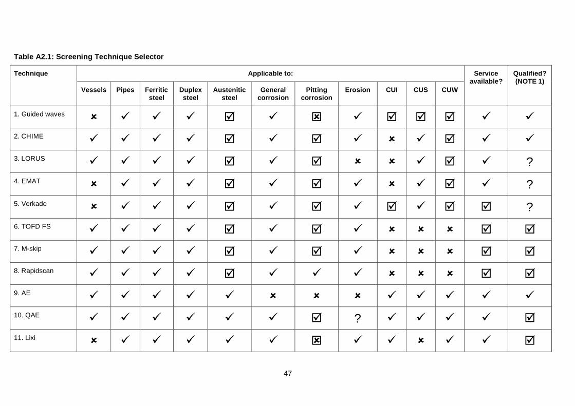
47
Table A2.1: Screening Technique Selector
Applicable to: Technique
Vessels Pipes Ferritic steel
Duplex steel
Austenitic steel
General corrosion
Pitting corrosion
Erosion CUI CUS CUW
Service available?
Qualified? (NOTE 1)
1. Guided waves 2. CHIME 3. LORUS ? 4. EMAT ? 5. Verkade ? 6. TOFD FS 7. M-skip 8. Rapidscan 9. AE 10. QAE ? 11. Lixi
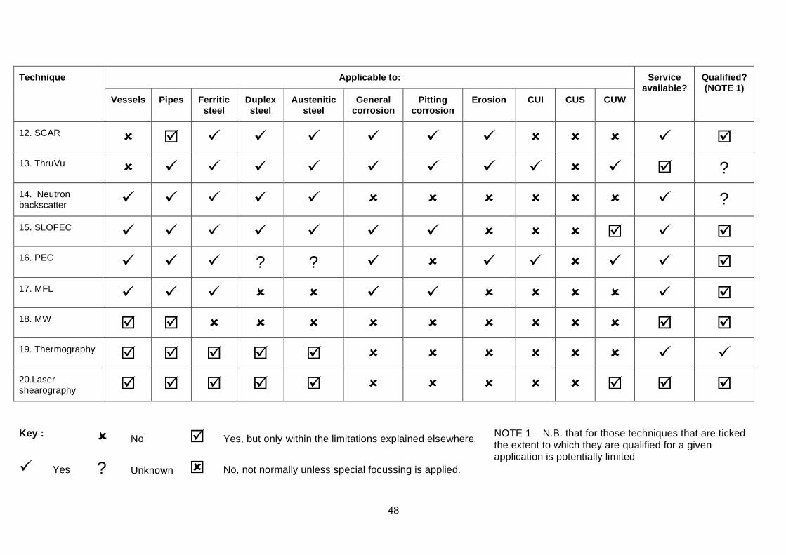
48
Applicable to: Technique
Vessels Pipes Ferritic steel
Duplex steel
Austenitic steel
General corrosion
Pitting corrosion
Erosion CUI CUS CUW
Service available?
Qualified? (NOTE 1)
12. SCAR 13. ThruVu ? 14. Neutron backscatter ? 15. SLOFEC 16. PEC ? ? 17. MFL 18. MW 19. Thermography 20.Laser shearography
Key : No Yes, but only within the limitations explained elsewhere
Yes ? Unknown No, not normally unless special focussing is applied.
NOTE 1 – N.B. that for those techniques that are ticked the extent to which they are qualified for a given application is potentially limited
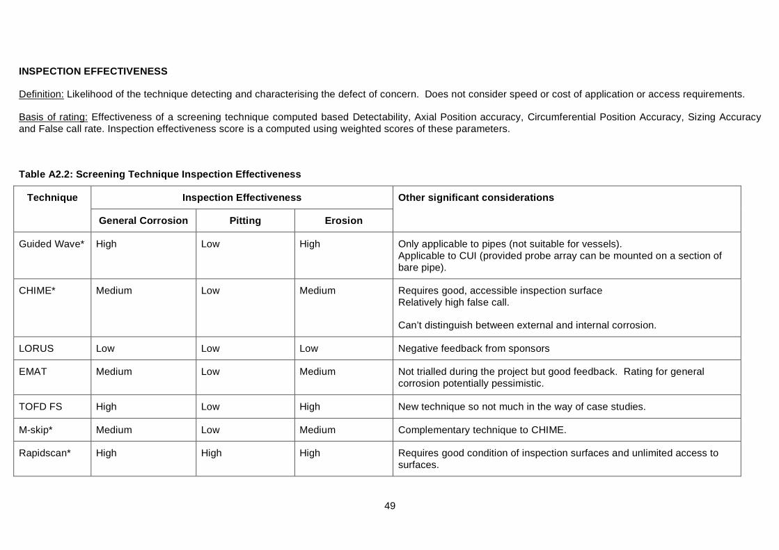
49
INSPECTION EFFECTIVENESS
Definition: Likelihood of the technique detecting and characterising the defect of concern. Does not consider speed or cost of application or access requirements.
Basis of rating: Effectiveness of a screening technique computed based Detectability, Axial Position accuracy, Circumferential Position Accuracy, Sizing Accuracy and False call rate. Inspection effectiveness score is a computed using weighted scores of these parameters.
Table A2.2: Screening Technique Inspection Effectiveness
Inspection Effectiveness Technique
General Corrosion Pitting Erosion
Other significant considerations
Guided Wave* High Low High Only applicable to pipes (not suitable for vessels). Applicable to CUI (provided probe array can be mounted on a section of bare pipe).
CHIME* Medium Low Medium Requires good, accessible inspection surface Relatively high false call.
Can’t distinguish between external and internal corrosion.
LORUS Low Low Low Negative feedback from sponsors
EMAT Medium Low Medium Not trialled during the project but good feedback. Rating for general corrosion potentially pessimistic.
TOFD FS High Low High New technique so not much in the way of case studies.
M-skip* Medium Low Medium Complementary technique to CHIME.
Rapidscan* High High High Requires good condition of inspection surfaces and unlimited access to surfaces.
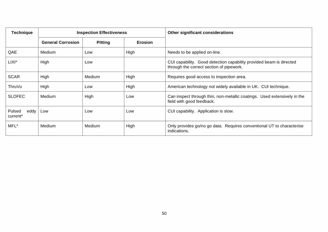
50
Inspection Effectiveness Technique
General Corrosion Pitting Erosion
Other significant considerations
QAE Medium Low High Needs to be applied on-line.
LIXI* High Low CUI capability. Good detection capability provided beam is directed through the correct section of pipework.
SCAR High Medium High Requires good access to inspection area.
ThruVu High Low High American technology not widely available in UK. CUI technique.
SLOFEC Medium High Low Can inspect through thin, non-metallic coatings. Used extensively in the field with good feedback.
Pulsed eddy current*
Low Low Low CUI capability. Application is slow.
MFL* Medium Medium High Only provides go/no go data. Requires conventional UT to characterise indications.
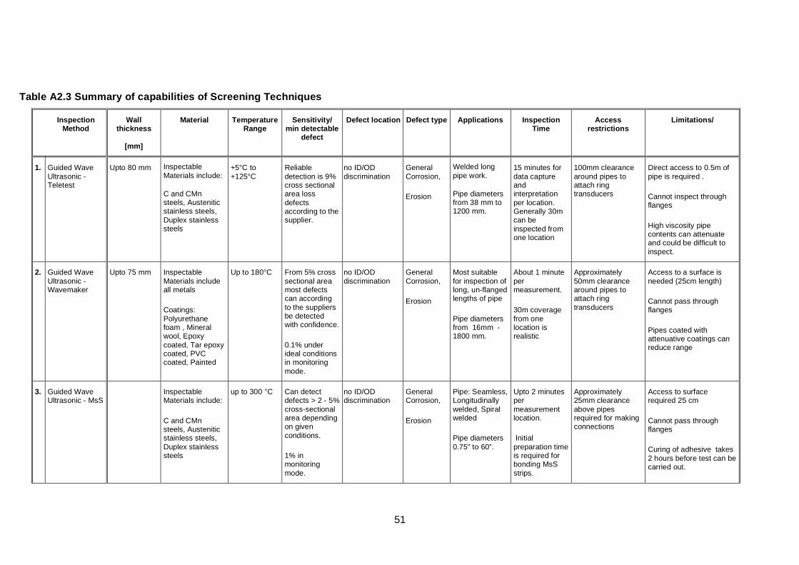
51
Table A2.3 Summary of capabilities of Screening Techniques
Inspection Method
Wall thickness
[mm]
Material Temperature Range
Sensitivity/ min detectable
defect
Defect location Defect type Applications Inspection Time
Access restrictions
Limitations/
1. Guided Wave Ultrasonic - Teletest
Upto 80 mm Inspectable Materials include:
C and CMn steels, Austenitic stainless steels, Duplex stainless steels
+5°C to +125°C
Reliable detection is 9% cross sectional area loss defects according to the supplier.
no ID/OD discrimination
General Corrosion,
Erosion
Welded long pipe work.
Pipe diameters from 38 mm to 1200 mm.
15 minutes for data capture and interpretation per location. Generally 30m can be inspected from one location
100mm clearance around pipes to attach ring transducers
Direct access to 0.5m of pipe is required .
Cannot inspect through flanges
High viscosity pipe contents can attenuate and could be difficult to inspect.
2. Guided Wave Ultrasonic - Wavemaker
Upto 75 mm Inspectable Materials include all metals
Coatings: Polyurethane foam , Mineral wool, Epoxy coated, Tar epoxy coated, PVC coated, Painted
Up to 180°C
From 5% cross sectional area most defects can according to the suppliers be detected with confidence.
0.1% under ideal conditions in monitoring mode.
no ID/OD discrimination
General Corrosion,
Erosion
Most suitable for inspection of long, un-flanged lengths of pipe
Pipe diameters from 16mm - 1800 mm.
About 1 minute per measurement.
30m coverage from one location is realistic
Approximately 50mm clearance around pipes to attach ring transducers
Access to a surface is needed (25cm length)
Cannot pass through flanges
Pipes coated with attenuative coatings can reduce range
3. Guided Wave Ultrasonic - MsS
Inspectable Materials include:
C and CMn steels, Austenitic stainless steels, Duplex stainless steels
up to 300 °C Can detect defects > 2 - 5% cross-sectional area depending on given conditions.
1% in monitoring mode.
no ID/OD discrimination
General Corrosion,
Erosion
Pipe: Seamless, Longitudinally welded, Spiral welded
Pipe diameters 0.75" to 60”.
Upto 2 minutes per measurement location.
Initial preparation time is required for bonding MsS strips.
Approximately 25mm clearance above pipes required for making connections
Access to surface required 25 cm
Cannot pass through flanges
Curing of adhesive takes 2 hours before test can be carried out.
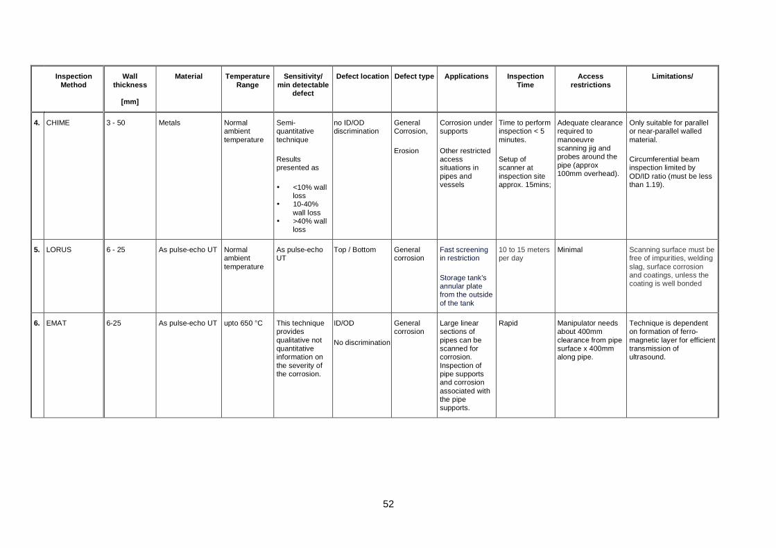
52
Inspection Method
Wall thickness
[mm]
Material Temperature Range
Sensitivity/ min detectable
defect
Defect location Defect type Applications Inspection Time
Access restrictions
Limitations/
4. CHIME 3 - 50 Metals Normal ambient temperature
Semi-quantitative technique
Results presented as
• <10% wall loss
• 10-40% wall loss
• >40% wall loss
no ID/OD discrimination
General Corrosion,
Erosion
Corrosion under supports
Other restricted access situations in pipes and vessels
Time to perform inspection < 5 minutes.
Setup of scanner at inspection site approx. 15mins;
Adequate clearance required to manoeuvre scanning jig and probes around the pipe (approx 100mm overhead).
Only suitable for parallel or near-parallel walled material.
Circumferential beam inspection limited by OD/ID ratio (must be less than 1.19).
5. LORUS 6 - 25 As pulse-echo UT Normal ambient temperature
As pulse-echo UT
Top / Bottom General corrosion
Fast screening in restriction
Storage tank's annular plate from the outside of the tank
10 to 15 meters per day
Minimal Scanning surface must be free of impurities, welding slag, surface corrosion and coatings, unless the coating is well bonded
6. EMAT 6-25 As pulse-echo UT upto 650 °C This technique provides qualitative not quantitative information on the severity of the corrosion.
ID/OD
No discrimination
General corrosion
Large linear sections of pipes can be scanned for corrosion. Inspection of pipe supports and corrosion associated with the pipe supports.
Rapid Manipulator needs about 400mm clearance from pipe surface x 400mm along pipe.
Technique is dependent on formation of ferro-magnetic layer for efficient transmission of ultrasound.
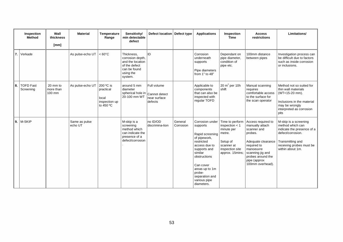
53
Inspection Method
Wall thickness
[mm]
Material Temperature Range
Sensitivity/ min detectable
defect
Defect location Defect type Applications Inspection Time
Access restrictions
Limitations/
7. Verkade As pulse-echo UT < 60°C
Thickness, corrosion depth, and the location of the defect can be found using the system.
ID Corrosion underneath supports
Pipe diameters from 1” to 48”
Dependant on pipe diameter, condition of pipe etc.
100mm distance between pipes
Investigation process can be difficult due to factors such as inside corrosion or inclusions.
8. TOFD Fast Screening
20 mm to more than 100 mm
As pulse-echo UT 200 ºC is practical
local inspection up to 450 ºC
around 5 mm diameter spherical hole in 20-100 mm WT
Full volume
Cannot detect near surface defects
Applicable to components that can also be inspected with regular TOFD
20 m2 per 10h shift
Manual scanning requires comfortable access to the surface for the scan operator
Method not so suited for thin wall materials (WT<15-20 mm).
Inclusions in the material may be wrongly interpreted as corrosion pits
9. M-SKIP Same as pulse echo UT
M-skip is a screening method which can indicate the presence of a defect/corrosion.
no ID/OD discrimina-tion
General Corrosion
Corrosion under supports
Rapid screening of pipework, restricted access due to supports and similar obstructions
Can cover areas up to 1m probe-separation and various pipe diameters.
Time to perform inspection < 1 minute per metre.
Setup of scanner at inspection site approx. 15mins;
Access required to manually attach scanner and probes.
Adequate clearance required to manoeuvre scanning jig and probes around the pipe (approx 100mm overhead).
M-skip is a screening method which can indicate the presence of a defect/corrosion.
Transmitting and receiving probes must be within about 1m.
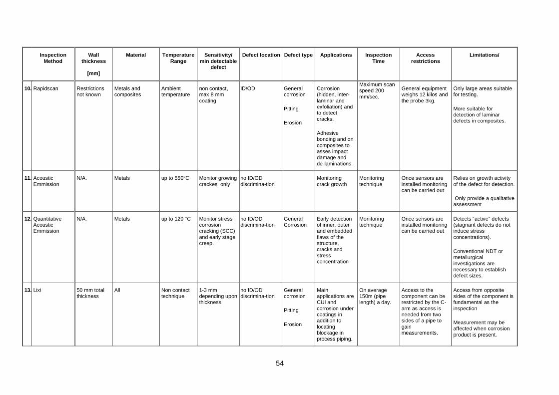
54
Inspection Method
Wall thickness
[mm]
Material Temperature Range
Sensitivity/ min detectable
defect
Defect location Defect type Applications Inspection Time
Access restrictions
Limitations/
10. Rapidscan Restrictions not known
Metals and composites
Ambient temperature
non contact, max 8 mm coating
ID/OD General corrosion
Pitting
Erosion
Corrosion (hidden, inter-laminar and exfoliation) and to detect cracks.
Adhesive bonding and on composites to asses impact damage and de-laminations.
Maximum scan speed 200 mm/sec.
General equipment weighs 12 kilos and the probe 3kg.
Only large areas suitable for testing.
More suitable for detection of laminar defects in composites.
11. Acoustic Emmission
N/A. Metals up to 550°C Monitor growing crackes only
no ID/OD discrimina-tion
Monitoring crack growth
Monitoring technique
Once sensors are installed monitoring can be carried out
Relies on growth activity of the defect for detection.
Only provide a qualitative assessment
12. Quantitative Acoustic Emmission
N/A. Metals up to 120 °C Monitor stress corrosion cracking (SCC) and early stage creep.
no ID/OD discrimina-tion
General Corrosion
Early detection of inner, outer and embedded flaws of the structure, cracks and stress concentration
Monitoring technique
Once sensors are installed monitoring can be carried out
Detects “active” defects (stagnant defects do not induce stress concentrations).
Conventional NDT or metallurgical investigations are necessary to establish defect sizes.
13. Lixi 50 mm total thickness
All Non contact technique
1-3 mm depending upon thickness
no ID/OD discrimina-tion
General corrosion
Pitting
Erosion
Main applications are CUI and corrosion under coatings in addition to locating blockage in process piping.
On average 150m (pipe length) a day.
Access to the component can be restricted by the C-arm as access is needed from two sides of a pipe to gain measurements.
Access from opposite sides of the component is fundamental as the inspection
Measurement may be affected when corrosion product is present.
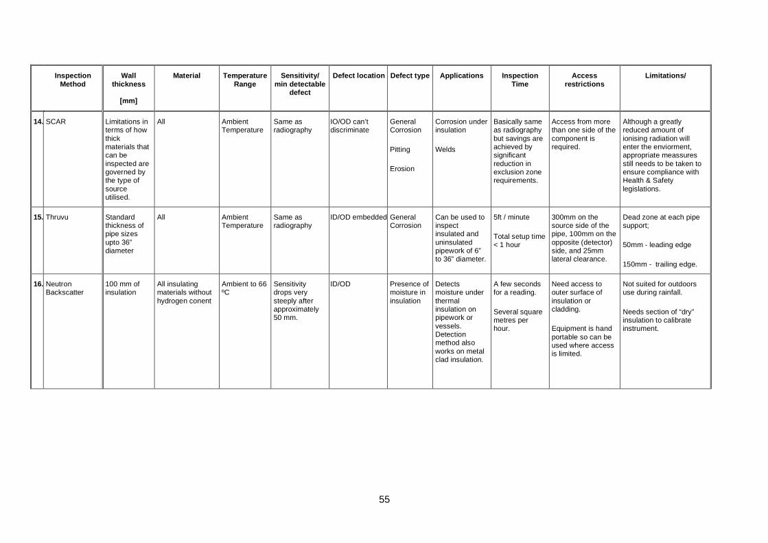
55
Inspection Method
Wall thickness
[mm]
Material Temperature Range
Sensitivity/ min detectable
defect
Defect location Defect type Applications Inspection Time
Access restrictions
Limitations/
14. SCAR Limitations in terms of how thick materials that can be inspected are governed by the type of source utilised.
All Ambient Temperature
Same as radiography
IO/OD can’t discriminate
General Corrosion
Pitting
Erosion
Corrosion under insulation
Welds
Basically same as radiography but savings are achieved by significant reduction in exclusion zone requirements.
Access from more than one side of the component is required.
Although a greatly reduced amount of ionising radiation will enter the enviorment, appropriate meassures still needs to be taken to ensure compliance with Health & Safety legislations.
15. Thruvu Standard thickness of pipe sizes upto 36” diameter
All Ambient Temperature
Same as radiography
ID/OD embedded General Corrosion
Can be used to inspect insulated and uninsulated pipework of 6” to 36” diameter.
5ft / minute
Total setup time < 1 hour
300mm on the source side of the pipe, 100mm on the opposite (detector) side, and 25mm lateral clearance.
Dead zone at each pipe support;
50mm - leading edge
150mm - trailing edge.
16. Neutron Backscatter
100 mm of insulation
All insulating materials without hydrogen conent
Ambient to 66 ºC
Sensitivity drops very steeply after approximately 50 mm.
ID/OD Presence of moisture in insulation
Detects moisture under thermal insulation on pipework or vessels. Detection method also works on metal clad insulation.
A few seconds for a reading.
Several square metres per hour.
Need access to outer surface of insulation or cladding.
Equipment is hand portable so can be used where access is limited.
Not suited for outdoors use during rainfall.
Needs section of “dry” insulation to calibrate instrument.
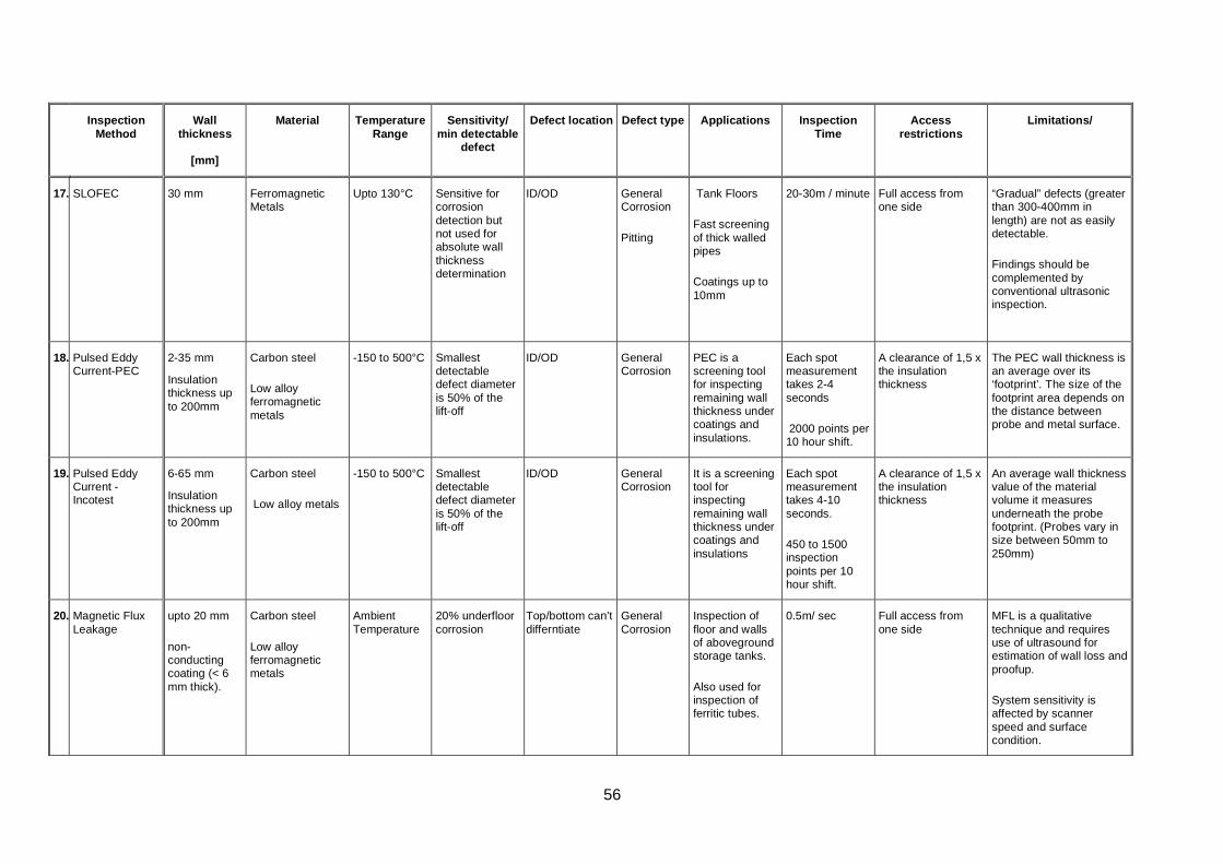
56
Inspection Method
Wall thickness
[mm]
Material Temperature Range
Sensitivity/ min detectable
defect
Defect location Defect type Applications Inspection Time
Access restrictions
Limitations/
17. SLOFEC 30 mm
Ferromagnetic Metals
Upto 130°C Sensitive for corrosion detection but not used for absolute wall thickness determination
ID/OD General Corrosion
Pitting
Tank Floors
Fast screening of thick walled pipes
Coatings up to 10mm
20-30m / minute Full access from one side
“Gradual” defects (greater than 300-400mm in length) are not as easily detectable.
Findings should be complemented by conventional ultrasonic inspection.
18. Pulsed Eddy Current-PEC
2-35 mm
Insulation thickness up to 200mm
Carbon steel
Low alloy ferromagnetic metals
-150 to 500°C Smallest detectable defect diameter is 50% of the lift-off
ID/OD General Corrosion
PEC is a screening tool for inspecting remaining wall thickness under coatings and insulations.
Each spot measurement takes 2-4 seconds
2000 points per 10 hour shift.
A clearance of 1,5 x the insulation thickness
The PEC wall thickness is an average over its ‘footprint’. The size of the footprint area depends on the distance between probe and metal surface.
19. Pulsed Eddy Current - Incotest
6-65 mm
Insulation thickness up to 200mm
Carbon steel
Low alloy metals
-150 to 500°C Smallest detectable defect diameter is 50% of the lift-off
ID/OD General Corrosion
It is a screening tool for inspecting remaining wall thickness under coatings and insulations
Each spot measurement takes 4-10 seconds.
450 to 1500 inspection points per 10 hour shift.
A clearance of 1,5 x the insulation thickness
An average wall thickness value of the material volume it measures underneath the probe footprint. (Probes vary in size between 50mm to 250mm)
20. Magnetic Flux Leakage
upto 20 mm
non-conducting coating (< 6 mm thick).
Carbon steel
Low alloy ferromagnetic metals
Ambient Temperature
20% underfloor corrosion
Top/bottom can’t differntiate
General Corrosion
Inspection of floor and walls of aboveground storage tanks.
Also used for inspection of ferritic tubes.
0.5m/ sec Full access from one side
MFL is a qualitative technique and requires use of ultrasound for estimation of wall loss and proofup.
System sensitivity is affected by scanner speed and surface condition.
57
Inspection Method
Wall thickness
[mm]
Material Temperature Range
Sensitivity/ min detectable
defect
Defect location Defect type Applications Inspection Time
Access restrictions
Limitations/
21. MFL Pipescan 19 mm
Coatings up to 6 mm.
Carbon steel
Low alloy ferromagnetic metals
-20OC and 100OC
The system has no sizing capabilities.
ID/OD can’t differentiate
Used as a screening tool, Pipescan is capable of detecting corrosion pitting originating from the internal and/or external surface of the pipe.
450mm per second
Full acces to the external surface of the pipe
A limited area adjacent to longitudinal welds is not covered.
Pipescan scanning heads cannot pass bends / elbows and severely distorted areas of pipe.
22. Microwave Applicable to non-conductive materials only
Embedded Disbonds Detection of defects such as delaminations, disbands and impact damage in dielectric materials such as fibre reinforced polymeric (FRP) materials.
Not specified, but unlikely to be rapid
Full acces to one side
Does not inspect sub surface defects in metal
Moisture or liquid may affect results
23. Thermography Surface technique
All -40°C up to +2000°C
Resolution up to 0.1°C
Detects presence of water
Measure water presence in insulation or damage of insulation through variations in surface temperature or to detect sand levels and build ups in pipe and vessels.
Real time Infrared instruments measure the energy from a circular spot on the target, the farther away from the target the sensor is, the larger the spot.
Results can be distorted if hot pipes and shiny cladding are present close to inspection area
58
Inspection Method
Wall thickness
[mm]
Material Temperature Range
Sensitivity/ min detectable
defect
Defect location Defect type Applications Inspection Time
Access restrictions
Limitations/
24. Laser Sheorography
100 mm All 5 ºC – 35 ºC The instrument can identify composite structural defects such as delaminations, disbonds, impact damage, voids, inclusions and cracks.
Rapid Access to restricted areas can be achieved using mirrors
Vibration of surrounding structure
Remarks: Defect location: OD is detect indications on far side, ID is near (probe) side, embedded defects
Defect type: Defects detected with High to Medium effectiveness by the technique during GSP236 lab trials

59
APPENDIX 3
IN-SERVICE SCREENING INSPECTION PLAN

60

61
In- Service Screening Inspection Plan Introduction
The screening inspection plan for a plant defines which parts of the plant will be inspected
using screening techniques, how much coverage is required and what screening techniques
will be used. Provisons of the in-service screening inspection plan described below are
generic in nature and coherent with Ref. 1.
One of the objectives of the plan is to determine whether screening inspection is the most
appropriate approach for the inspection or a different level of inspection in more appropriate.
The guiding principle is that based on the type of degradation expected in the plant, right
type of inspection is selected so that the integrity of the plant is maintained till the next
inspection. Screening inspection may detect conditions in the plant leading to further
investigation using more sensitive techniques for confirmation of the type of degradation and
sizing.
After it has been determined through technical and economic considerations that screening
inspection is the appropriate route some degree of iteration may be required during the
development of inspection plan.
Although the approach is intended to be systematic, it does not remove the need for input
and review by competent personnel. The purpose of this guide is to formalise the steps
involved in planning a screening inspection and thereby promote a systematic and
consistent approach to the overall inspection strategy.
For this reason, the results must be reviewed by competent inspection planning personnel to
check that the screening inspection plan is broadly consistent with their engineering
judgment.
The decision process and flowchart approach are designed to be flexible and can be tailored
to the needs of different plant operators. For example different users might adopt different
definitions (and different numbers of levels) for likelihood of degradation, inspection
effectiveness required, and consequence of failure. However the same general logic to the
decision process can be maintained.
62
General Approach
An effective screening inspection plan depends upon applying the most appropriate
screening techniques and coverage to the various parts of the plant.
This is achieved by first dividing the plant into different zones representing different
combinations of geometry, material, potential degradation mechanisms, and likelihood of
degradation. The inspection requirements can then be decided on a zone by zone basis.
The inspection effectiveness (combination of capability and coverage) required for each
zone will depend on the likelihood of degradation and the tolerance to degradation in that
zone. The required effectiveness will also be influenced by the consequence of plant
equipment failure. Clearly there is likely to be a strong incentive to perform a rigourous
inspection (e.g. full coverage using a sensitive inspection method which has a high
probability of detecting defects) for a part of an equipment where likelihood of degradation is
high, tolerance to further degradation is low, and consequence of plant / equipment failure is
high. However less expensive methods based on rapid (but reduced sensitivity) screening
methods or even sample inspections might be acceptable for other zones in the same plant /
equipment, or where the consequence of failure is low. Some zones might not require any
inspection.
A decision process based on a flowchart approach is presented which provides guidance on
the inspection effectiveness required for a zone, taking into account for each zone whether
degradation has previously been detected, the likelihood of degradation, current tolerance to
degradation and consequence of vessel failure.
Identification of Zones
The plant should be divided into one or more “zones” representing different combinations of
likelihood of degradation and tolerance to degradation. Factors such as geometry, material,
likelihood of degradation, type of degradation and previous inspection results should all be
considered when identifying these different zones. This then provides the basis for deciding
which parts (zones) of the plant should be inspected, what inspection effectiveness is
required, and which should be subject to screening inspections. In the case of screening
inspection of a zone, it may be possible that some areas of concern will be detected.
Genrally, follow up detailed targeted inspection using more sensitive conventional
techniques may be required over the area identified by the screening inspection for further
investigation regarding the type of degradation and the extent of the degradation.
63
Factors which should be considered when dividing the plant into zones include the following:
Design and manufacturing factors: The plant is divided into different zones (categories)
based on loading conditions and tolerance to defects.
Examples include, but are not limited to: insulated piping, buried / embedded piping,
pressure vessel shell plates, heads/dished ends, nozzles (set on, set through and forged
nozzle designs might need to be treated separately), inlets, manways, longitudinal welds,
circumferential welds, internal attachments, internal components. Separate parts might be
included in the same zone, e.g. all nozzles might belong to the same zone, welds might be
included in the same zone regardless of welding process or geometry.
Operational factors. The plant is divided into different zones reflecting the extent to which
different locations are known or expected to be affected by the operating and process
conditions. Considerations include, but are not limited to: service fluids, inlet/outlet locations,
locations of mixed phases, high fluid flow rates and turbulence and impingement,
vapour/condensation, bubbling/cavitation, pressure/pressure cycling, loading, temperature,
oxidizing atmosphere, aggressive abrasive content. This requires detailed knowledge of the
operational characteristics, chemical nature of the fluids, metallurgy etc. Previous
experience of the plant, similar plants and equipment in similar service, and similar materials
subject to similar operating / process conditions should be taken into account.
Previous inspection factors. The plant is divided into different zones corresponding to the
effectiveness and results of previous inspections. Examples include, but are not limited to,
regions where no previous in-service inspections have been performed, regions subjected to
internal visual inspection, regions subject to ultrasonic thickness measurements, regions
reported to contain defects / degradation etc.
Known Degradation
The first step is to follow the appropriate strand in the flowchart (Figure A1) corresponding to
whether or not degradation (other than superficial) in the zone under consideration has
previously been detected.
Likelihood of Degradation
The next step in the flowchart is to determine whether the likelihood of degradation (other
than superficial) is high, medium or low.
64
In the absence of other criteria, the following definitions could apply:
Low: No evidence of degradation in this zone from the same or similar plants in the same or
similar service. Negligible potential for degradation.
Medium: No evidence of degradation in this zone from similar plants operating under
similar conditions but potential for degradation identified.
High: Evidence of degradation from similar plants operating under similar conditions or
degradation expected.
(Note that if degradation has previously been reported, the likelihood defaults to “high”)
Current Tolerance to Degradation
The current tolerance to degradation should be considered in terms of whether it is low,
medium or high.
In the absence of other criteria, the following definitions could apply:
Low: The known or predicted degradation and rate thereof in the zone under consideration
are such that failure of the plant / equipment (if no remedial action is taken) can reasonably
be expected within the remaining plant lifetime.
Medium: The known or predicted degradation and rate thereof in the zone under
consideration are such as to be observable during the plant lifetime but would not be
expected to threaten the vessel during this period or require remedial action.
High: There is no degradation expected or degradation is superficial.
Consequence of Failure
The minimum inspection effectiveness required for the zone under consideration depends on
the consequence of plant / equipment failure. The health, safety and environmental
consequences of failure should be considered separately from the business interruption and
cost consequences, and whichever of these is the higher is the level that should be used.
The consequence of failure should be determined, in terms of whether it is high, medium or
low. In the absence of other criteria, the following definitions could apply:
65
Health, Safety and Environmental Consequences
High: One or more fatalities or serious injuries requiring hospital treatment, or major release
of hazardous material or pollution.
Medium: Injury requiring hospital treatment, or release of hazardous material or pollution
but with no significant effect off site.
Low: At most, minor injury with full recovery, or minimal release of hazardous material or
pollution.
Business Interruption and Cost Consequences
In the absence of other criteria, the following definitions could apply:
High: Major shutdown or high costs of repair / replacement
Medium: Several days shutdown or significant costs of repair / replacement
Low: Less than one day shutdown or low costs of repair / replacement
Minimum Inspection Effectiveness Required
The flowchart provides a “score” which represents the minimum level of inspection
effectiveness proposed for the zone under consideration. These requirements should be
interpreted as follows.
0: No inspection of the zone is required
1: Spot checks. The inspection is performed at a number of discrete locations within
the zone, for example manual ultrasonic thickness measurements at 500mm
intervals might be appropriate for monitoring general loss of wall thickness, or at a
reduced interval for more localised corrosion/erosion.
2: 100% inspection. 100% inspection of the zone be carried out using a screening
method which has medium or high inspection effectiveness for the type of
degradation expected. Inspection effectiveness is a measure of probability of
detecting degradation or defects of concern, it also takes into account defect sizing,
false call rate, positioning accuracy. Statistical approach for high sensitivity
66
inspection over sufficienly large area may be adopted, in case none of the screening
techniques is deemed to have the necessary level of inspection effectiveness for the
type of degradation being investigated.
3: 100% inspection of the zone using a method which has high efficiency, i.e. expected
to have a probability of detection exceeding 90% for the degradation or defects of
concern. 100% screening using technique with High Effectiveness should also be
evaluated.
Note: The inspection requirements for a zone may need to be increased if defects or
degradation are detected during the inspection. For example if spot checks reveal
greater loss of wall thickness than expected, or localised thinning, increased
coverage is recommended to properly assess the extent of the thinning. If cracks are
detected during a sample inspection, 100% inspection of that zone (and other
susceptible zones) may be required.
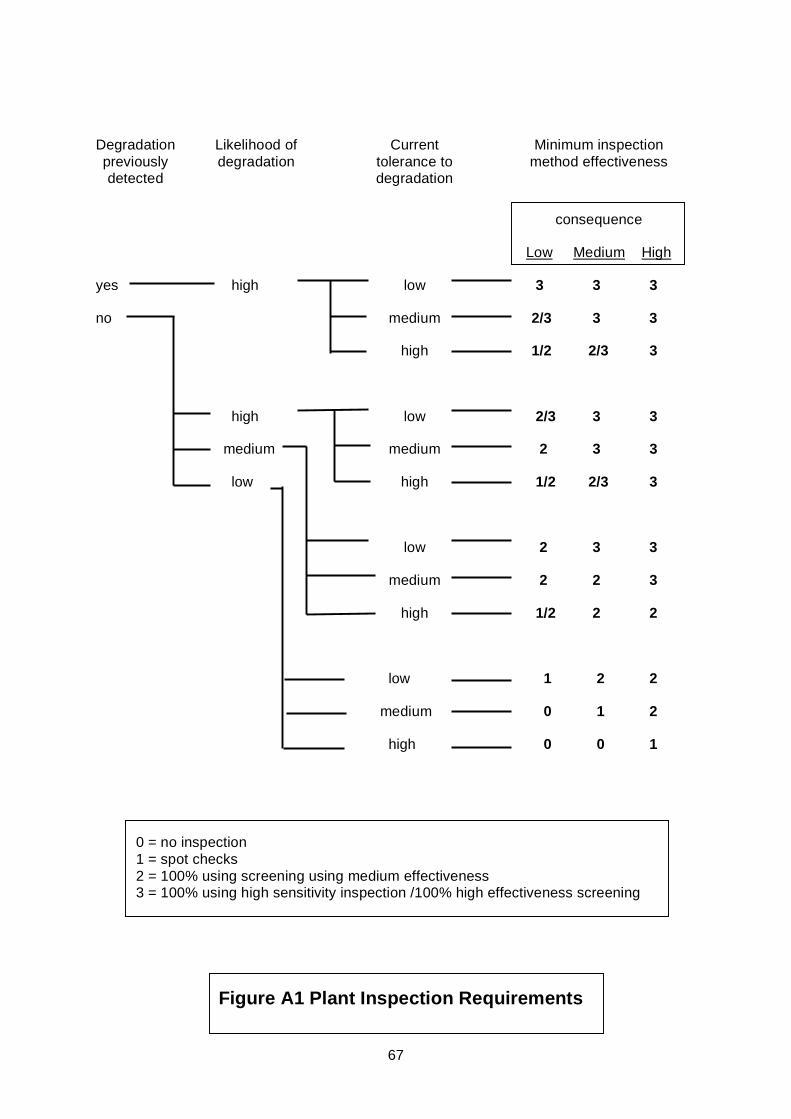
67
Degradation previously detected
Likelihood of degradation
Current tolerance to degradation
Minimum inspection method effectiveness
consequence
Low Medium High
yes high low 3 3 3
no medium 2/3 3 3
high 1/2 2/3 3
high low 2/3 3 3
medium medium 2 3 3
low high 1/2 2/3 3
low 2 3 3
medium 2 2 3
high 1/2 2 2
low 1 2 2
medium 0 1 2
high 0 0 1
0 = no inspection 1 = spot checks 2 = 100% using screening using medium effectiveness 3 = 100% using high sensitivity inspection /100% high effectiveness screening
Figure A1 Plant Inspection Requirements

68

69
APPENDIX 4
GSP236 Steering Committee Members
Health & Safety Executive ExxonMobil Shell UK (supported by Shell Global Solutions) BP ConocoPhillips Lloyds Register Sabic UK (originally Huntsman) Statoil Hydro Oil & Energy Petrobras Oceaneering TWI Aker Kvaerner (withdrew halfway through project due to closure of affected business unit)
This report contains notes on good practice which are not compulsory, but which you may find helpful in considering what you need to do.

70

71
APPENDIX 5
DATASHEETS

72
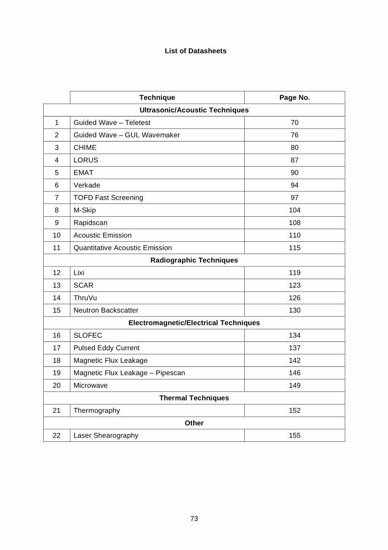
73
List of Datasheets
Technique Page No.
Ultrasonic/Acoustic Techniques
1 Guided Wave – Teletest 70
2 Guided Wave – GUL Wavemaker 76
3 CHIME 80
4 LORUS 87
5 EMAT 90
6 Verkade 94
7 TOFD Fast Screening 97
8 M-Skip 104
9 Rapidscan 108
10 Acoustic Emission 110
11 Quantitative Acoustic Emission 115
Radiographic Techniques
12 Lixi 119
13 SCAR 123
14 ThruVu 126
15 Neutron Backscatter 130
Electromagnetic/Electrical Techniques
16 SLOFEC 134
17 Pulsed Eddy Current 137
18 Magnetic Flux Leakage 142
19 Magnetic Flux Leakage – Pipescan 146
20 Microwave 149
Thermal Techniques
21 Thermography 152
Other
22 Laser Shearography 155
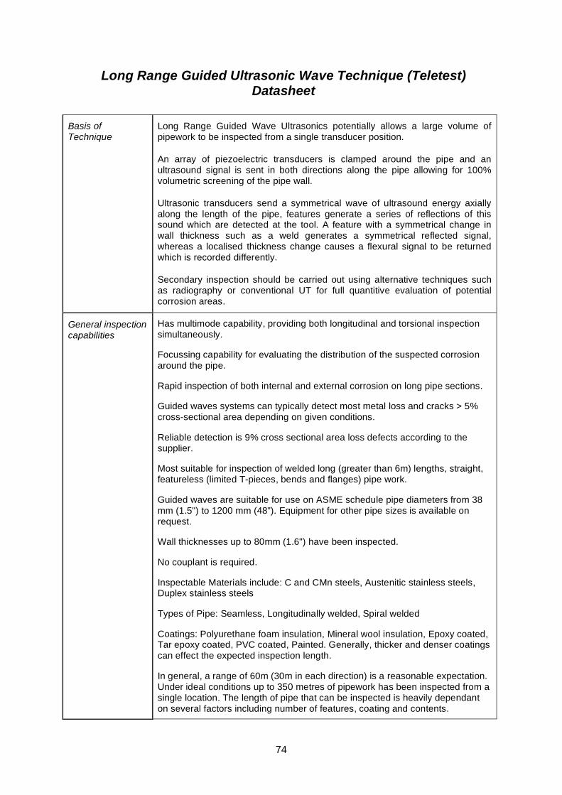
74
Long Range Guided Ultrasonic Wave Technique (Teletest) Datasheet
Basis of Technique
Long Range Guided Wave Ultrasonics potentially allows a large volume of pipework to be inspected from a single transducer position.
An array of piezoelectric transducers is clamped around the pipe and an ultrasound signal is sent in both directions along the pipe allowing for 100% volumetric screening of the pipe wall.
Ultrasonic transducers send a symmetrical wave of ultrasound energy axially along the length of the pipe, features generate a series of reflections of this sound which are detected at the tool. A feature with a symmetrical change in wall thickness such as a weld generates a symmetrical reflected signal, whereas a localised thickness change causes a flexural signal to be returned which is recorded differently.
Secondary inspection should be carried out using alternative techniques such as radiography or conventional UT for full quantitive evaluation of potential corrosion areas.
General inspection capabilities
Has multimode capability, providing both longitudinal and torsional inspection simultaneously.
Focussing capability for evaluating the distribution of the suspected corrosion around the pipe.
Rapid inspection of both internal and external corrosion on long pipe sections.
Guided waves systems can typically detect most metal loss and cracks > 5% cross-sectional area depending on given conditions.
Reliable detection is 9% cross sectional area loss defects according to the supplier.
Most suitable for inspection of welded long (greater than 6m) lengths, straight, featureless (limited T-pieces, bends and flanges) pipe work.
Guided waves are suitable for use on ASME schedule pipe diameters from 38 mm (1.5") to 1200 mm (48”). Equipment for other pipe sizes is available on request.
Wall thicknesses up to 80mm (1.6") have been inspected.
No couplant is required.
Inspectable Materials include: C and CMn steels, Austenitic stainless steels, Duplex stainless steels
Types of Pipe: Seamless, Longitudinally welded, Spiral welded
Coatings: Polyurethane foam insulation, Mineral wool insulation, Epoxy coated, Tar epoxy coated, PVC coated, Painted. Generally, thicker and denser coatings can effect the expected inspection length.
In general, a range of 60m (30m in each direction) is a reasonable expectation. Under ideal conditions up to 350 metres of pipework has been inspected from a single location. The length of pipe that can be inspected is heavily dependant on several factors including number of features, coating and contents.
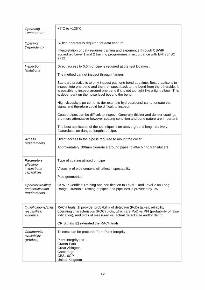
75
Operating Temperature
+5°C to +125°C.
Operator Dependency
Skilled operator is required for data capture.
Interpretation of data requires training and experience through CSWIP accredited Level 1 and 2 training programmes in accordance with EN473/ISO 9712.
Inspection limitations
Direct access to 0.5m of pipe is required at the test location .
The method cannot inspect through flanges
Standard practice is to only inspect past one bend at a time. Best practise is to inspect into one bend and then reinspect back to the bend from the otherside. It is possible to inspect around one bend if it is not too tight like a tight elbow. This is dependent on the noise level beyond the bend.
High viscosity pipe contents (for example hydrocarbons) can attenuate the signal and therefore could be difficult to inspect.
Coated pipes can be difficult to inspect. Generally thicker and denser coatings are more attenuative however coating condition and bond nature are important.
The best application of the technique is on above-ground long, relatively featureless, un-flanged lengths of pipe.
Access requirements
Direct access to the pipe is required to mount the collar
Approximately 100mm clearance around pipes to attach ring transducers
Parameters affecting inspections capabilities
Type of coating utilised on pipe
Viscosity of pipe content will affect inspectability
Pipe geometries
Operator training and certification requirements
CSWIP Certified Training and certification to Level-1 and Level-2 on Long Range ultrasonic Testing of pipes and pipelines is provided by TWI.
Qualifications/trials results/field evidence
RACH trials [1] provide: probability of detection (PoD) tables; reliability operating characteristics (ROC) plots, which are PoD vs PFI (probability of false indication); and plots of measured vs. actual defect size and/or depth.
CRIS trials [2] extended the RACH trials.
Commercial availability (product)
Teletest can be procured from Plant Integrity
Plant Integrity Ltd Granta Park Great Abington Cambridge CB21 6GP United Kingdom
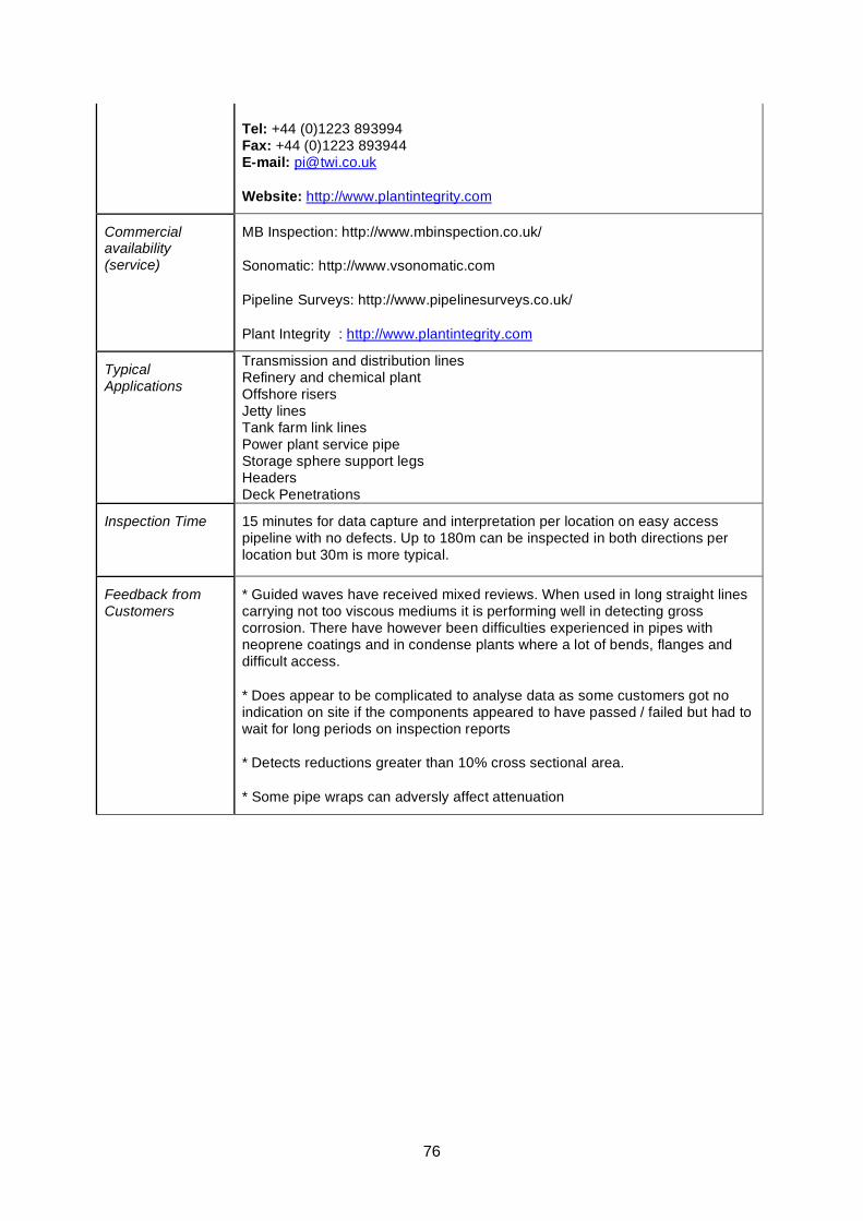
76
Tel: +44 (0)1223 893994 Fax: +44 (0)1223 893944 E-mail: [email protected]
Website: http://www.plantintegrity.com
Commercial availability (service)
MB Inspection: http://www.mbinspection.co.uk/
Sonomatic: http://www.vsonomatic.com
Pipeline Surveys: http://www.pipelinesurveys.co.uk/
Plant Integrity : http://www.plantintegrity.com
Typical Applications
Transmission and distribution lines Refinery and chemical plant Offshore risers Jetty lines Tank farm link lines Power plant service pipe Storage sphere support legs Headers Deck Penetrations
Inspection Time 15 minutes for data capture and interpretation per location on easy access pipeline with no defects. Up to 180m can be inspected in both directions per location but 30m is more typical.
Feedback from Customers
* Guided waves have received mixed reviews. When used in long straight lines carrying not too viscous mediums it is performing well in detecting gross corrosion. There have however been difficulties experienced in pipes with neoprene coatings and in condense plants where a lot of bends, flanges and difficult access.
* Does appear to be complicated to analyse data as some customers got no indication on site if the components appeared to have passed / failed but had to wait for long periods on inspection reports
* Detects reductions greater than 10% cross sectional area.
* Some pipe wraps can adversly affect attenuation
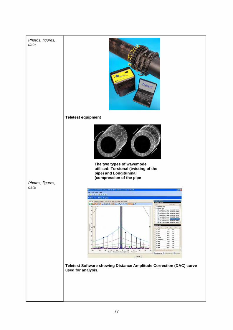
77
Photos, figures, data
Photos, figures, data
Teletest equipment
Teletest Software showing Distance Amplitude Correction (DAC) curve used for analysis.
The two types of wavemode utilised: Torsional (twisting of the pipe) and Longituninal (compression of the pipe
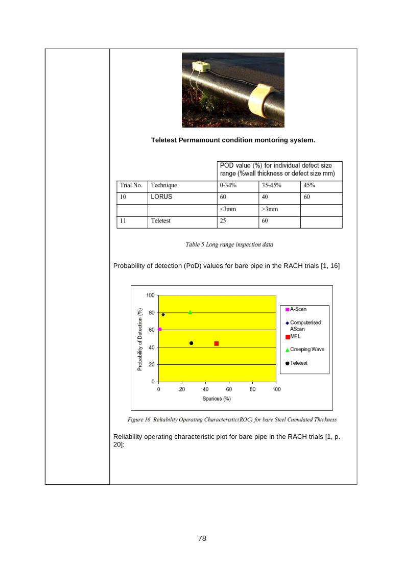
78
Teletest Permamount condition montoring system.
Probability of detection (PoD) values for bare pipe in the RACH trials [1, 16]
Reliability operating characteristic plot for bare pipe in the RACH trials [1, p. 20]:

79
Links http://www.plantintegrity.co.uk/
RACH report [1] on HSE website (PDF, 494 KB).
References [1] Reliability assessment for containers of hazardous material RACH, Technical Software Consultants Limited for the HSE, Offshore Technology Report 2000/095, 2001.
[2] Corrosion Reliability Inspection Scheduling (access restricted to HOIS2000 members)
80
Guided Ultrasonic Wave Technique (Wavemaker) Datasheet
Basis of Technique
* Guided Wave (UT) allows a large area of pipework to be inspected from a single transducer position.
* The Guided Wave (GW) travels along the length of the pipe and is reflected by changes in pipe stiffness (ncluding changes in acoustic impedance)
• A symmetrical change in wall thickness generates a uniformly reflected signal whereby a localised thickness change is recorded differently.
• A unit of piezoelectric transducers is clamped around the pipe and the GW are sent simultaneously in both directions along the pipe with 100% screening coverage within its diagnostic length.
General inspection capabilities
* Rapid inspection of both internal and external defects on long pipe sections.
*Wavemaker technology is available both in screening and monitoring configuration (PIMS)
*Wavemaker technology is available both with external or internal access transduction system. T-scan (internal access system) is used to screen structures such as heat exchanger tubes.
*Wavemaker technology is also used for underwater inspection of risers and other pipelines
*Wavemaker G3 in screening configuration can detect metal loss and cracks > 1% cross-sectional area depending on given conditions. From 5% cross sectional area most defects can according to the suppliers be detected with confidence.
*Wavemaker G3 in monitoring configuration can detect defects as small as 0.1% of the cross sectional area.
* Most suitable for inspection of long, un-flanged lengths of pipe.
* Guided waves are suitable for use on pipe diameters from 16mm (3/4") - 1800 mm (72”). Inflatable rings need to be used for bigger pipes.
* Wall thicknesses up to 75mm (3”) have been inspected.
* No couplant is required.
* Inspectable Materials include all metals
* Types of Pipe: Seamless, Longitudinally welded, Spiral welded
* Coatings: Polyurethane foam insulation, Mineral wool insulation, Epoxy coated, Tar epoxy coated, PVC coated, Painted.
* Other: Under ideal conditions roughly 100m can be inspected in a single test. The length of pipe that can be inspected is heavily dependant on several factors and range can be much lower than ideal case.
Operating Temperature
Up to 180 degrees C
81
Operator Dependency
This guided wave technology is an advanced inspection method so operator expertise is a vital ingredient.
GUL training has been proven to give reliable results in terms of classification of experience level needed for specific applications.
Inspection limitations
* Access to a surface is needed (360 degreed over 25cm axial length)
* The method cannot pass through flanges and does not inspect flanges.
* Standard practice is to only inspect past one bend at a time.
* High viscosity of the pipe content (for example bitumen) will attenuate the signal and can therefore be difficult to inspect.
* Pipes coated with attenuative coatings (e.g. soft thick and well adhered bitumen) can reduce range (or sensitivity). Coating condition and bond nature affect the ease of inspection, both of which can change after operational application.
Access requirements
* Close access to inspection components to mount transducer ring
* Approximately 50mm clearance around pipes to attach ring transducers
Parameters affecting inspections capabilities
* The frequency of ultrasound will govern how small or big defect can be detected but higher frequency resulting in higher sensitivity will decrease the range.
* Type of coating utilised on pipe
* Viscosity of pipe content will affect inspectability
* Pipe geometries and condition.
Internal deposits and lining
Operator training and certification requirements
Guided Ultrasonics Limited offer Level-I and Level-II training and certification.
Qualifications/trials results/field evidence
RACH trials [1] provide: probability of detection (PoD) tables; reliability operating characteristics (ROC) plots, which are PoD vs PFI (probability of false indication); and plots of measured vs. actual defect size and/or depth.
CRIS trials [2] extended the RACH trials.
Commercial availability (product)
Guided Ultrasonics Ltd
17 Doverbeck Close Nottingham NG15 9ER United Kingdom
Fax: +44 (0) 1623 491 093
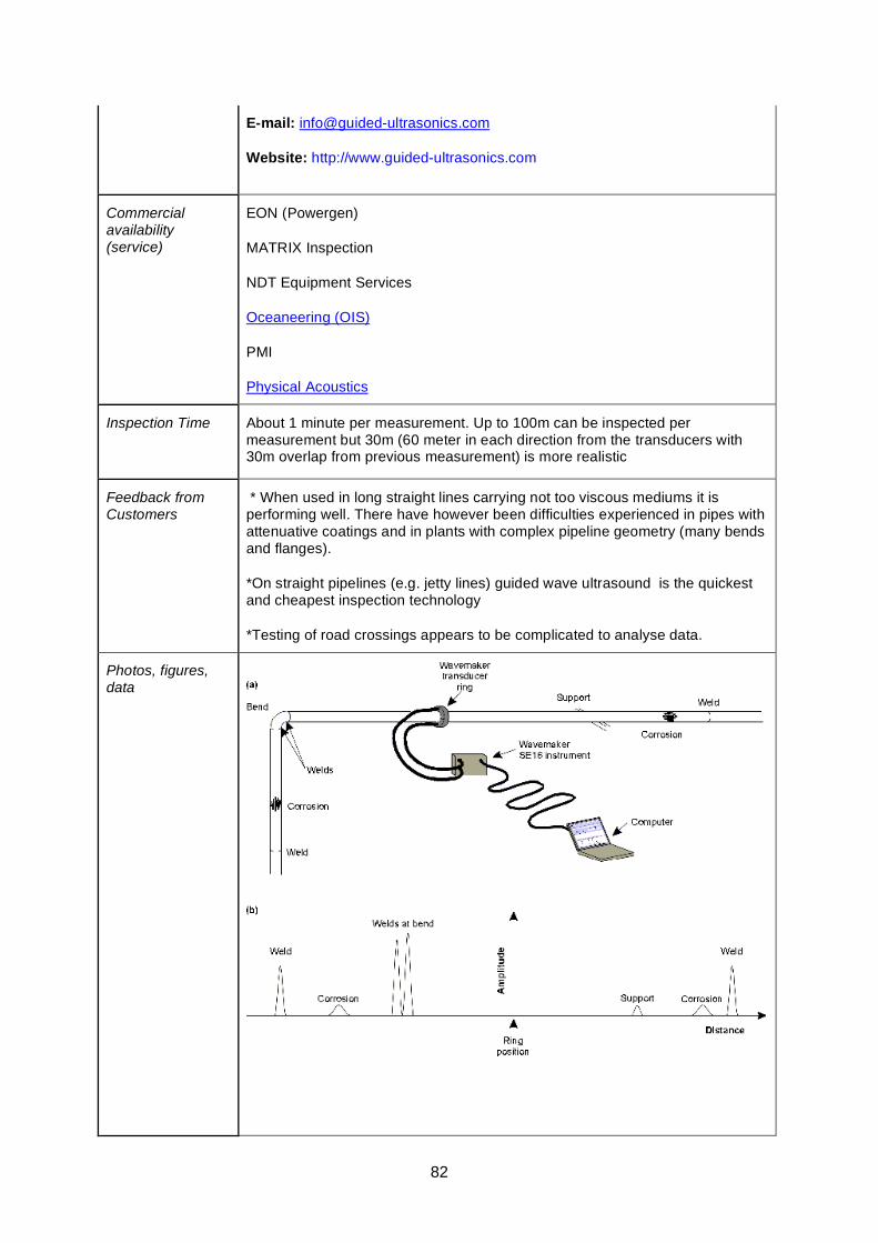
82
E-mail: [email protected]
Website: http://www.guided-ultrasonics.com
Commercial availability (service)
EON (Powergen)
MATRIX Inspection
NDT Equipment Services
Oceaneering (OIS)
PMI
Physical Acoustics
Inspection Time About 1 minute per measurement. Up to 100m can be inspected per measurement but 30m (60 meter in each direction from the transducers with 30m overlap from previous measurement) is more realistic
Feedback from Customers
* When used in long straight lines carrying not too viscous mediums it is performing well. There have however been difficulties experienced in pipes with attenuative coatings and in plants with complex pipeline geometry (many bends and flanges).
*On straight pipelines (e.g. jetty lines) guided wave ultrasound is the quickest and cheapest inspection technology
*Testing of road crossings appears to be complicated to analyse data.
Photos, figures, data
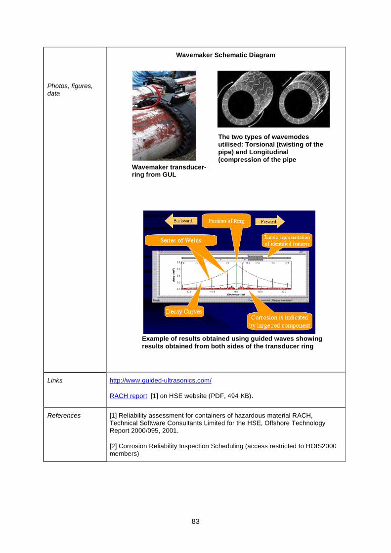
83
Photos, figures, data
Wavemaker Schematic Diagram
Links http://www.guided-ultrasonics.com/
RACH report [1] on HSE website (PDF, 494 KB).
References [1] Reliability assessment for containers of hazardous material RACH, Technical Software Consultants Limited for the HSE, Offshore Technology Report 2000/095, 2001.
[2] Corrosion Reliability Inspection Scheduling (access restricted to HOIS2000 members)
Wavemaker transducer-ring from GUL
The two types of wavemodes utilised: Torsional (twisting of the pipe) and Longitudinal (compression of the pipe
Example of results obtained using guided waves showing results obtained from both sides of the transducer ring
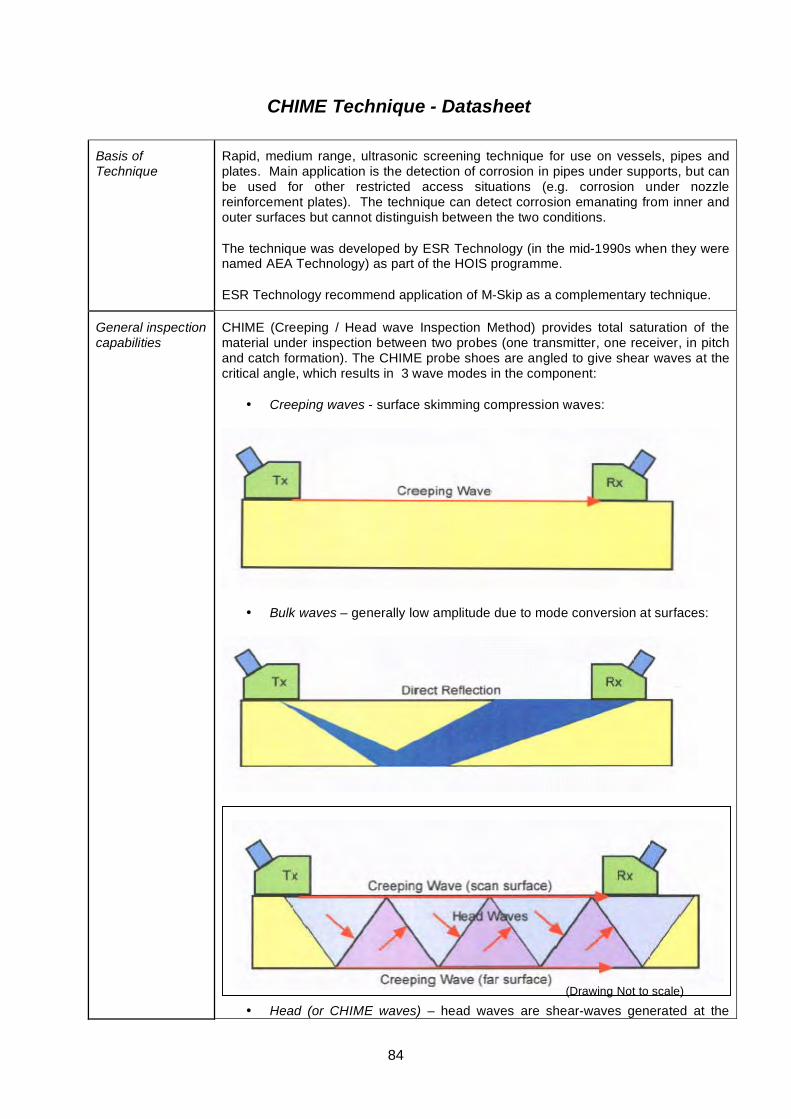
84
CHIME Technique - Datasheet
Basis of Technique
Rapid, medium range, ultrasonic screening technique for use on vessels, pipes and plates. Main application is the detection of corrosion in pipes under supports, but can be used for other restricted access situations (e.g. corrosion under nozzle reinforcement plates). The technique can detect corrosion emanating from inner and outer surfaces but cannot distinguish between the two conditions.
The technique was developed by ESR Technology (in the mid-1990s when they were named AEA Technology) as part of the HOIS programme.
ESR Technology recommend application of M-Skip as a complementary technique.
General inspection capabilities
CHIME (Creeping / Head wave Inspection Method) provides total saturation of the material under inspection between two probes (one transmitter, one receiver, in pitch and catch formation). The CHIME probe shoes are angled to give shear waves at the critical angle, which results in 3 wave modes in the component:
• Creeping waves - surface skimming compression waves:
• Bulk waves – generally low amplitude due to mode conversion at surfaces:
• Head (or CHIME waves) – head waves are shear-waves generated at the (Drawing Not to scale)
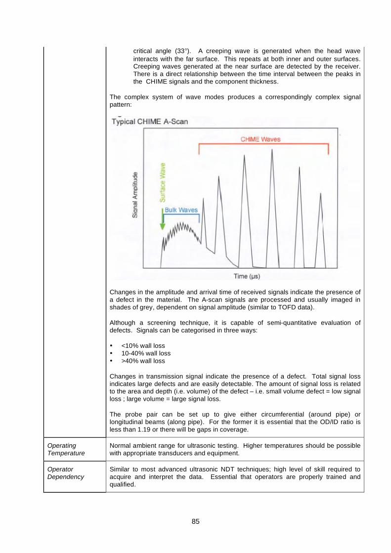
85
critical angle (33°). A creeping wave is generated when the head wave interacts with the far surface. This repeats at both inner and outer surfaces. Creeping waves generated at the near surface are detected by the receiver. There is a direct relationship between the time interval between the peaks in the CHIME signals and the component thickness.
The complex system of wave modes produces a correspondingly complex signal pattern:
Changes in the amplitude and arrival time of received signals indicate the presence of a defect in the material. The A-scan signals are processed and usually imaged in shades of grey, dependent on signal amplitude (similar to TOFD data).
Although a screening technique, it is capable of semi-quantitative evaluation of defects. Signals can be categorised in three ways:
• <10% wall loss • 10-40% wall loss • >40% wall loss
Changes in transmission signal indicate the presence of a defect. Total signal loss indicates large defects and are easily detectable. The amount of signal loss is related to the area and depth (i.e. volume) of the defect – i.e. small volume defect = low signal loss ; large volume = large signal loss.
The probe pair can be set up to give either circumferential (around pipe) or longitudinal beams (along pipe). For the former it is essential that the OD/ID ratio is less than 1.19 or there will be gaps in coverage.
Operating Temperature
Normal ambient range for ultrasonic testing. Higher temperatures should be possible with appropriate transducers and equipment.
Operator Dependency
Similar to most advanced ultrasonic NDT techniques; high level of skill required to acquire and interpret the data. Essential that operators are properly trained and qualified.
86
Inspection limitations
Suitable for pipes >75mm diameter for circumferential beams. For axial beams, there is no restriction on diameter.
For axial beams, the distance between the transmitting and receiving probes should be less than about 1m. For circumferential beams, the circumferential distance between probes should be less than about 700mm.
Suitable for thicknesses in the range 3 - 50mm.
Semi-quantitative only.
Only suitable for parallel or near-parallel walled material. Signals break up when wall thickness changes by 1mm over 75mm (13%).
Circumferential beam inspection limited by OD/ID ratio (must be less than 1.19). Inspections can still be carried out on materials with a larger ratio but full volume coverage cannot be guaranteed.
There is no limit when probes are axially pointing.
The lateral extent of the area of wall loss, in the direction orthogonal to the ultrasound beam, needs to be comparable with or larger than the diameter of the CHIME probe crystals (typically > 15mm), to give a significant loss in amplitude of the CHIME signals. Wall losses down to c. 10% of wall thickness can then be detected with high reliability, as demonstrated in the RACH, CRIS and GSP 236 trials.
Loss of CHIME signal amplitude can occur under a number of circumstances including:
• Cushion between pipe and support, which damps the creeping waves
• The presence of coatings
• Slight surface roughness on either the inspection surface or backwall.
• Loss of, or reduced coupling efficiency
The above mechanisms for loss of signal may limit the applicability of the technique, or if localised, could be mistaken for wall loss flaws (i.e. false calls). Experience to date indicates that the bulk waves signals are less sensitive to the above mechanisms than the CHIME peak signals.
Access requirements
Access required to manually attach scanner and probes. Adequate clearance required to manoeuvre scanning jig and probes around the pipe (approx 100mm overhead).
Surface condition requirements as for any UT inspection.
Parameters affecting inspections capabilities
Good surface preparation required as with all contact ultrasonic techniques. Good coupling required for transmission of ultrasound – this is monitored by a separate 0º probe, preferably mounted on the same shoe as the CHIME probe (with common index points).
Some reports of processing materials on internal surface of component adversely affecting quality of data.
87
Can be used in pulse-echo (p-e) mode to provide additional info on defect type. However, corrosion type defects are not readily detected by p-e.
Operator training and certification requirements
ESR Technology offers training and certification.
Qualifications/trials results/field evidence
CHIME was developed under the HOIS programme.
Doosan Babcock lab trials have proved successful in determining presence of defects of varying volumes. Field evidence (RPS) backs up lab trials.
RACH trials [1] provide: probability of detection (PoD) tables; reliability operating characteristics (ROC) plots, which are PoD vs PFI (probability of false indication); and plots of measured vs. actual defect size and/or depth.
CRIS trials [2] extended the RACH trials. On their website, ESR Technology state that in these blind trials, the CHIME technique achieved an overall PoD of > 94%.
Commercial availability (product)
ESR Technology (ex-AEA Technology, Harwell) has registered CHIME as a trademark; they also hold a patent for the technique. Inspection vendors require a licence to operate this technique, which is available from
ESR Technology Ltd 16 North Central 127 Milton Park Abingdon Oxfordshire OX14 4SA Tel: +44 (0)1235 213400 Fax: +44 (0)1235 213401 Email: [email protected]
www.esrtechnology.com
Suitable software and hardware is available from some specialist NDT suppliers.
Commercial availability (service)
Service can be procured via ESR Technology or any of their licencees which include:
• AGR EMI team http://www.agr.com/en/Our-Services/Field-Operations/Integrity-Services/NDT--Services/
• Sonomatic - www.vsonomatic.com
• Doosan Babcock - www.doosanbabcock.com
Inspection Time Rapid inspection: setup time on laptop pre-job approximately 30mins; setup of scanner at inspection site approx. 15mins; time to perform inspection < 5 minutes.
On their website, ESR Technology states that CHIME has a scan speed of around 1 m/min.
Feedback from Customers
Very good, verified results reported by at least one vendor and customer.
Others have reported adverse results due to process materials adhering to inner pipe surface.
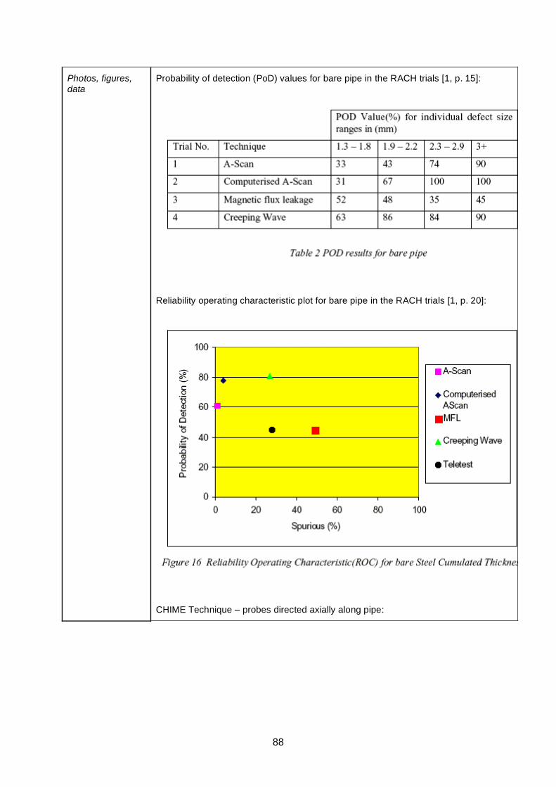
88
Photos, figures, data
Probability of detection (PoD) values for bare pipe in the RACH trials [1, p. 15]:
Reliability operating characteristic plot for bare pipe in the RACH trials [1, p. 20]:
CHIME Technique – probes directed axially along pipe:
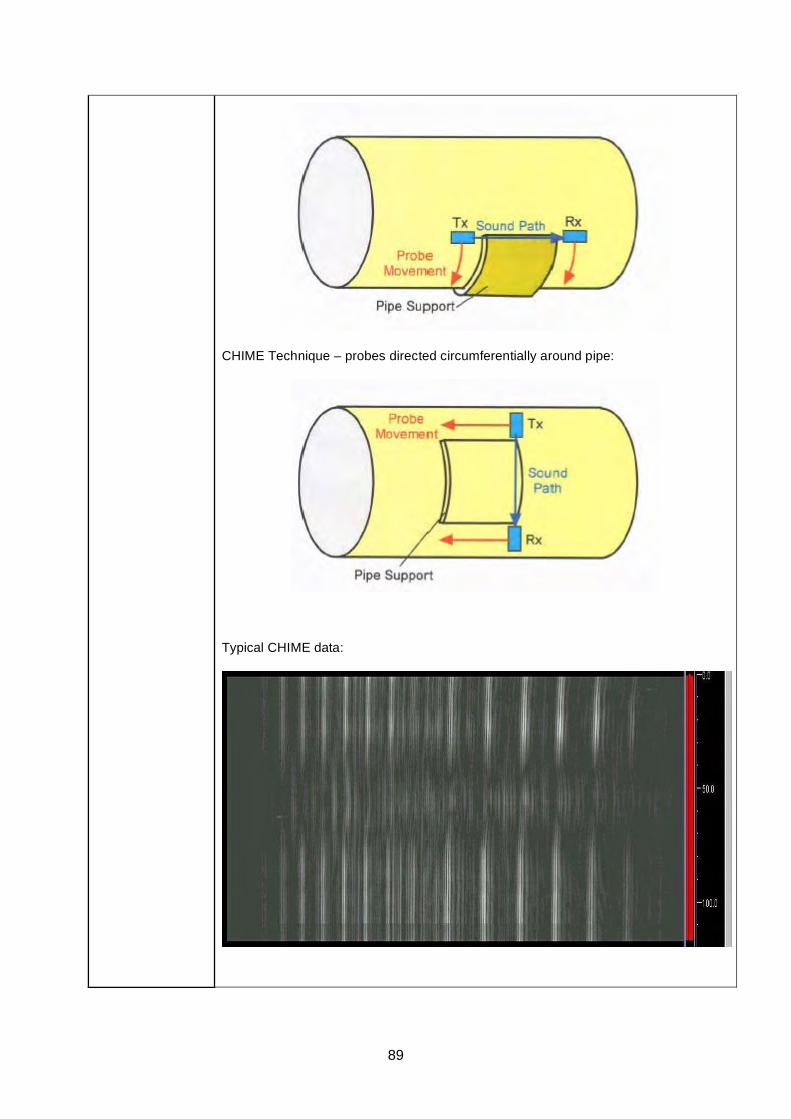
89
CHIME Technique – probes directed circumferentially around pipe:
Typical CHIME data:

90
Links CHIME Technical Paper
CHIME Technical Paper on ESR Technology website (PDF, 161 KB)
CHIME on the ESR Technology website
RACH report [1] on HSE website (PDF, 494 KB).
References [1] Reliability assessment for containers of hazardous material RACH, Technical Software Consultants Limited for the HSE, Offshore Technology Report 2000/095, 2001.
[2] Corrosion Reliability Inspection Scheduling (access restricted to HOIS2000 members)
91
LORUS ( Long Range Ultrasonic System ) Technique Datasheet
Basis of Technique
LORUS applies high sensitivity angle beam transducers in combination with an ultrasonic data recording system. The ultrasonic wave travels over multiple skips into the hard-to-access region. The presence of corrosion is established in the pulse-echo reflection mode. Reflection signals can be recorded together with 3-axis position encoder information. Coherent projection maps are calculated, showing directly location and extent of corrosion in one-to-one images.
General inspection capabilities
LORUS has been developed for fast screening of hard-to-access locations, such as detection of corrosion in a storage tank's annular plate from the outside of the tank. From a single access point, a large region may be inspected without direct access to the surface. Corrosion detection is achieved over a considerable distance (typically up to 1 meter). Compact manual scanners are applied in case of limited access and mechanized scanners are applied where possible for high inspection speed.
- range up to 1 metre - suitable for any tank diameter - suitable for annular plates from 6 to 25mm thick - ability to detect severe (pitting) corrosion - ability to detect local gradual corrosion - corrosion mapping and area estimation - suitable for corrosion growth monitoring - reflectivity of corroded areas may be used to estimate severity
Operating Temperature
Inspection at ambient temperature. No information available for use at elevated temperatures.
Operator Dependency
As with advanced Ultrasonic NDT techniques, skilled operator is required for data capture and interpretation.
Inspection limitations
- complete coverage of tank floor is not possible - no discrimination between top and reverse side corrosion - the scanning surface must be free of impurities, welding slag, surface corrosion and coatings, unless the coating is well bonded. - poor annular ring condition may affect the inspection range.
Access requirements
Minimal. Deployed remotely from corrosion site.
Parameters affecting inspections capabilities
Defect morphology.
Operator training and certification requirements
Information on specialized training for LORUS is not available.
Qualifications/trials results/field evidence
RACH trials [1] provide: probability of detection (PoD) tables; reliability operating characteristics (ROC) plots, which are PoD vs PFI (probability of false indication); and plots of measured vs. actual defect size and/or depth.
CRIS trials [2] extended the RACH trials.
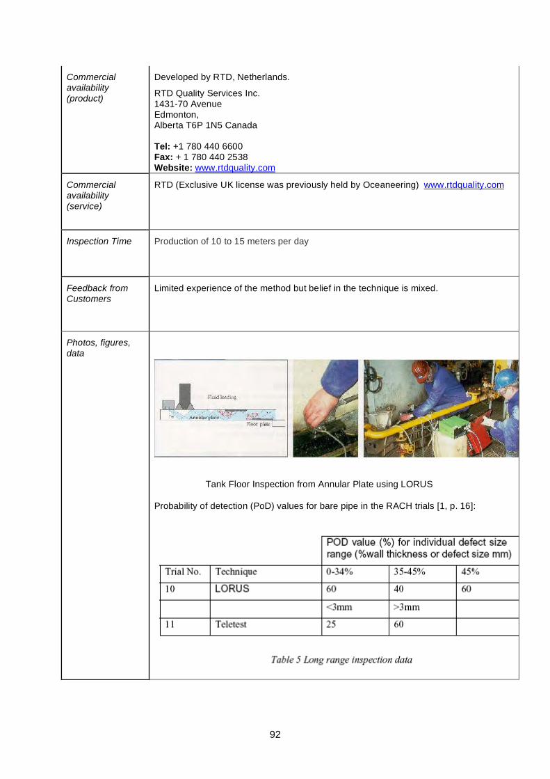
92
Commercial availability (product)
Developed by RTD, Netherlands.
RTD Quality Services Inc. 1431-70 Avenue Edmonton, Alberta T6P 1N5 Canada Tel: +1 780 440 6600 Fax: + 1 780 440 2538 Website: www.rtdquality.com
Commercial availability (service)
RTD (Exclusive UK license was previously held by Oceaneering) www.rtdquality.com
Inspection Time Production of 10 to 15 meters per day
Feedback from Customers
Limited experience of the method but belief in the technique is mixed.
Photos, figures, data
Tank Floor Inspection from Annular Plate using LORUS
Probability of detection (PoD) values for bare pipe in the RACH trials [1, p. 16]:
93
Links http://www.rtdquality.com/
http://www.oceaneering.com/index.htm
LORUS RTD
LORUS Oceaneering
RACH report [1] on HSE website (PDF, 494 KB).
References [1] Reliability assessment for containers of hazardous material RACH, Technical Software Consultants Limited for the HSE, Offshore Technology Report 2000/095, 2001.
[2] Corrosion Reliability Inspection Scheduling (access restricted to HOIS2000 members)
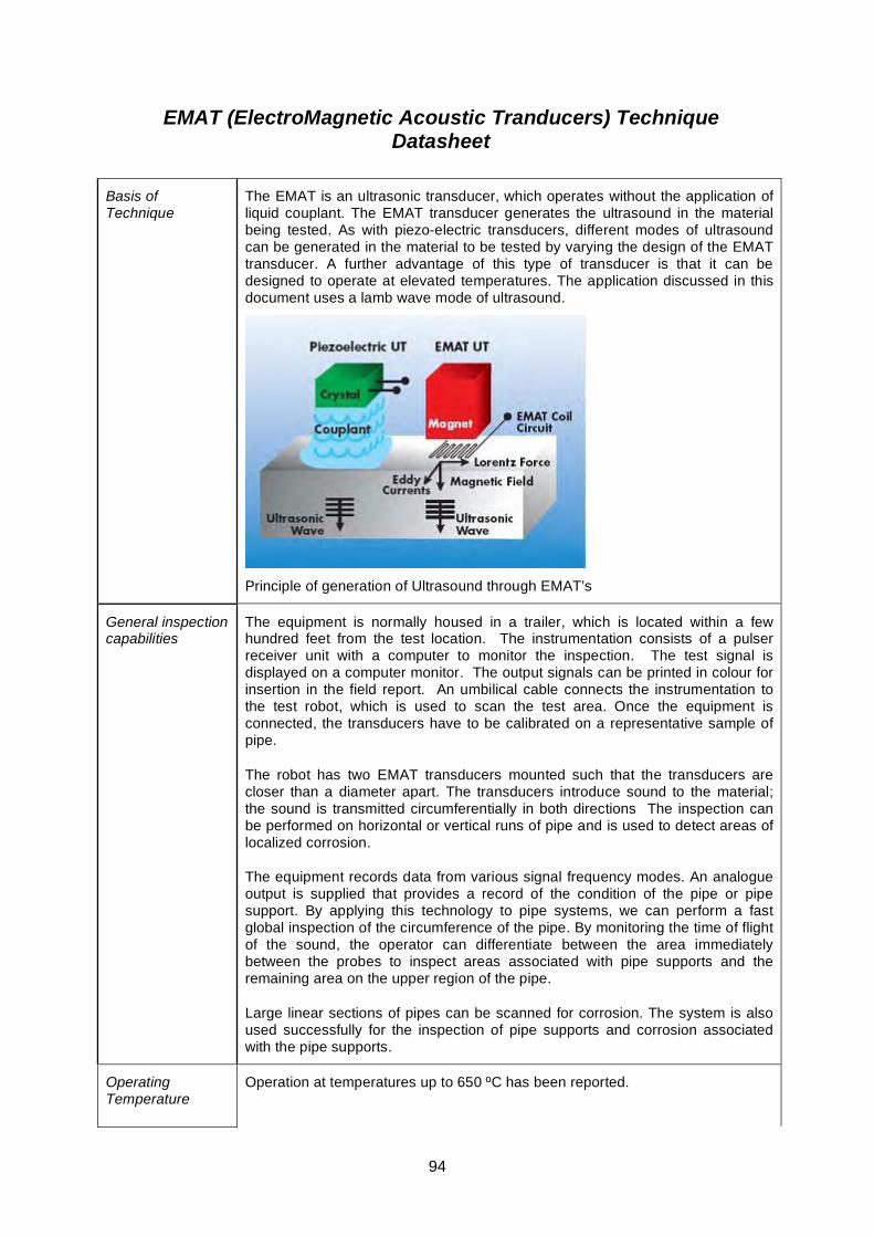
94
EMAT (ElectroMagnetic Acoustic Tranducers) Technique Datasheet
Basis of Technique
The EMAT is an ultrasonic transducer, which operates without the application of liquid couplant. The EMAT transducer generates the ultrasound in the material being tested. As with piezo-electric transducers, different modes of ultrasound can be generated in the material to be tested by varying the design of the EMAT transducer. A further advantage of this type of transducer is that it can be designed to operate at elevated temperatures. The application discussed in this document uses a lamb wave mode of ultrasound.
Principle of generation of Ultrasound through EMAT’s
General inspection capabilities
The equipment is normally housed in a trailer, which is located within a few hundred feet from the test location. The instrumentation consists of a pulser receiver unit with a computer to monitor the inspection. The test signal is displayed on a computer monitor. The output signals can be printed in colour for insertion in the field report. An umbilical cable connects the instrumentation to the test robot, which is used to scan the test area. Once the equipment is connected, the transducers have to be calibrated on a representative sample of pipe.
The robot has two EMAT transducers mounted such that the transducers are closer than a diameter apart. The transducers introduce sound to the material; the sound is transmitted circumferentially in both directions The inspection can be performed on horizontal or vertical runs of pipe and is used to detect areas of localized corrosion.
The equipment records data from various signal frequency modes. An analogue output is supplied that provides a record of the condition of the pipe or pipe support. By applying this technology to pipe systems, we can perform a fast global inspection of the circumference of the pipe. By monitoring the time of flight of the sound, the operator can differentiate between the area immediately between the probes to inspect areas associated with pipe supports and the remaining area on the upper region of the pipe.
Large linear sections of pipes can be scanned for corrosion. The system is also used successfully for the inspection of pipe supports and corrosion associated with the pipe supports.
Operating Temperature
Operation at temperatures up to 650 ºC has been reported.
95
Operator Dependency
Same as with Ultrasonics.
Inspection limitations
The technique detects but does not discriminate between corrosion on inner or outer surfaces of the pipe.
This technique provides qualitative not quantitative information on the severity of the corrosion.
Technique is dependent on formation of ferro-magnetic layer for efficient transmission of ultrasound.
Access requirements
Manipulator needs about 400mm clearance from pipe surface x 400mm along pipe.
Parameters affecting inspections capabilities
Surface condition
Material and construction
Geometry
Operating temperature
Operator training and certification requirements
Training and certification on operation on equipment can be provided by the supplier.
Qualifications/trials results/field evidence
The HOIS Interactive Knowledge Base summary of the PISC II trials results [1] plots an average probability of detection (PoD) of 85% for the EMAT technique.
ASTM E1774-96 Standard Guide for Electromagnetic Acoustic Transducers (EMATs)
ASTM E1816-96 Standard Practice for Ultrasonic Examinations Using Electromagnetic Acoustic Transducer (EMAT) Technology
ASTM E1962-98 Standard Test Methods for Ultrasonic Surface Examinations Using Electromagnetic Acoustic Transducer (EMAT) Technology
Commercial availability (product)
Product and service provided by InnerSpec Technologies, Mechanical Integrity Inc.
Innerspec Technologies, Inc. Global Headquarters 4004 Murray Place Lynchburg, VA 24501 Tel: + 1 434 948 1301 Fax: + 1434 948 1313 Website: http://www.innerspec.com Mechanical Integrity Inc, PO Box 398, Humble, Texas 77347 Phone 1 281 540 0314 Fax 1 281 540 0317
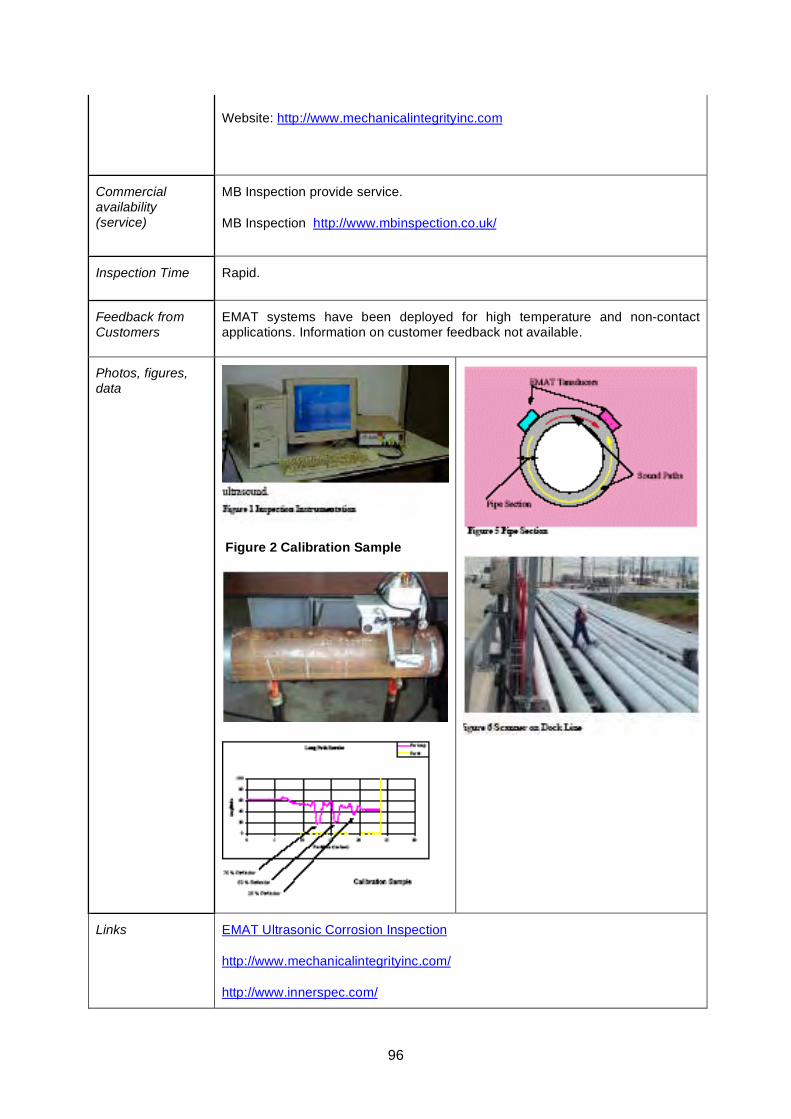
96
Website: http://www.mechanicalintegrityinc.com
Commercial availability (service)
MB Inspection provide service.
MB Inspection http://www.mbinspection.co.uk/
Inspection Time Rapid.
Feedback from Customers
EMAT systems have been deployed for high temperature and non-contact applications. Information on customer feedback not available.
Photos, figures, data
Figure 2 Calibration Sample
Links EMAT Ultrasonic Corrosion Inspection
http://www.mechanicalintegrityinc.com/
http://www.innerspec.com/

97
http://www.sonicsensors.com/
HOIS Interactive Knowledge Base
PISC II Report No. 5 (Programme for the Inspection of Steel Components) [1]
References [1] Evaluation of the PISC II trials results, PISC II Report No. 5 (Final Issue), Commision of the European Communities S.P./I.07.C1.86.62, OECD-NEA-CSNI No. 121, September 1986.
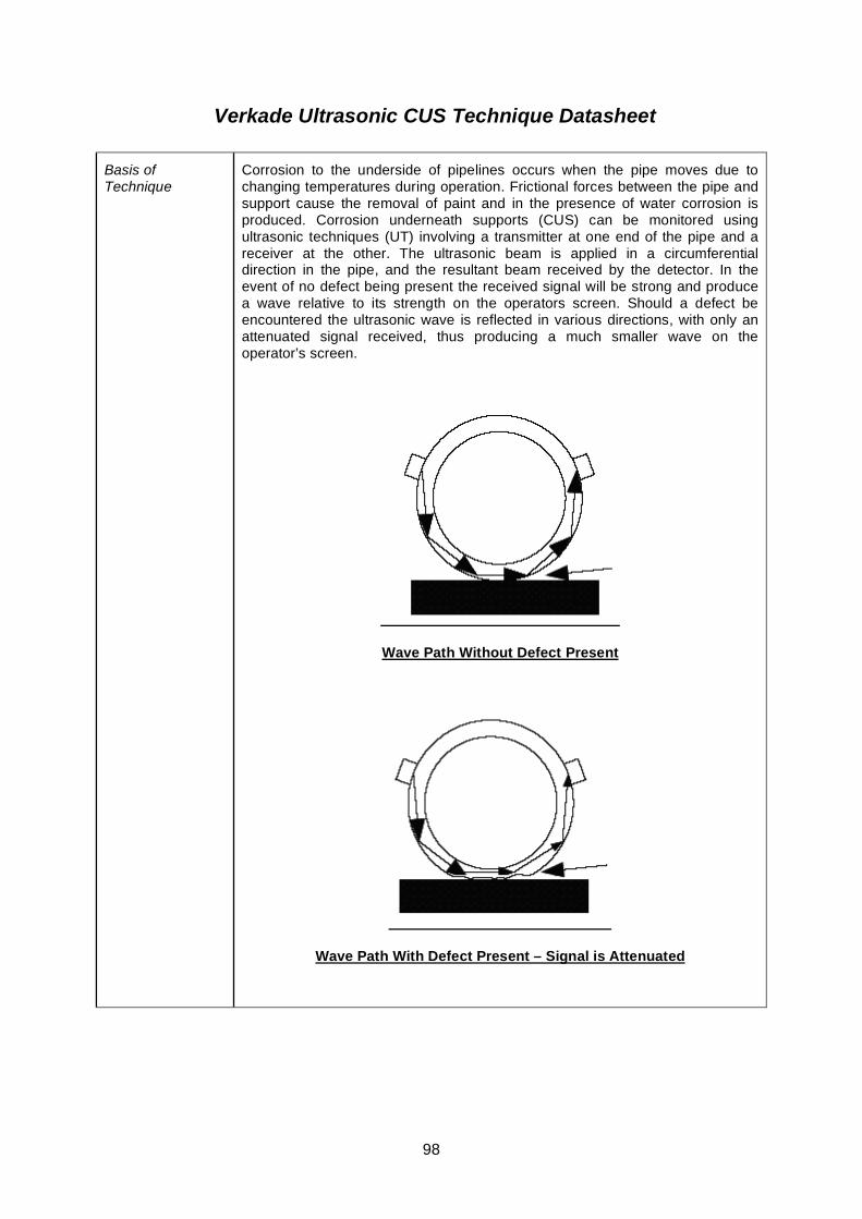
98
Verkade Ultrasonic CUS Technique Datasheet
Basis of Technique
Corrosion to the underside of pipelines occurs when the pipe moves due to changing temperatures during operation. Frictional forces between the pipe and support cause the removal of paint and in the presence of water corrosion is produced. Corrosion underneath supports (CUS) can be monitored using ultrasonic techniques (UT) involving a transmitter at one end of the pipe and a receiver at the other. The ultrasonic beam is applied in a circumferential direction in the pipe, and the resultant beam received by the detector. In the event of no defect being present the received signal will be strong and produce a wave relative to its strength on the operators screen. Should a defect be encountered the ultrasonic wave is reflected in various directions, with only an attenuated signal received, thus producing a much smaller wave on the operator’s screen.
Wave Path Without Defect Present
Wave Path With Defect Present – Signal is Attenuated
99
General inspection capabilities
On surfaces with temperatures up to 60 ºC (140 ºF).
Pipe diameters from 1” to 48” (The test depth is dependant on the permeability of the pipe surface as well as the condition of the surface coating.)
Sensitivity of the measurement process can be adjusted as required.
Thickness, corrosion depth, and the location of the defect can be found using the system.
Operating Temperature
< 60 ºC
Operator Dependency
Yes.
Inspection limitations
Temperatures up to 60 ºC (140 ºF).
Investigation process can be difficult due to factors such as inside corrosion or inclusions.
Access requirements
Pipes should be lying on supports at the time of inspection.
100mm distance between pipes.
Parameters affecting inspections capabilities
Surface condition.
Internal corrosion.
Operator training and certification requirements
Service is provided by the experts from Verkade NDT Services, the originators of the technology.
Qualifications/trials results/field evidence
Information not available.
Commercial availability (product)
Not available for sale.
Commercial availability (service)
Verkade NDT Services (Germany).
Verkade NDT Services GmbH An der Grotte 2 49716 Meppen-Versen Germany
Phone: ++49 5931 17312
Fax: ++49 5931 14731
Website: http://www.verkadendt.de
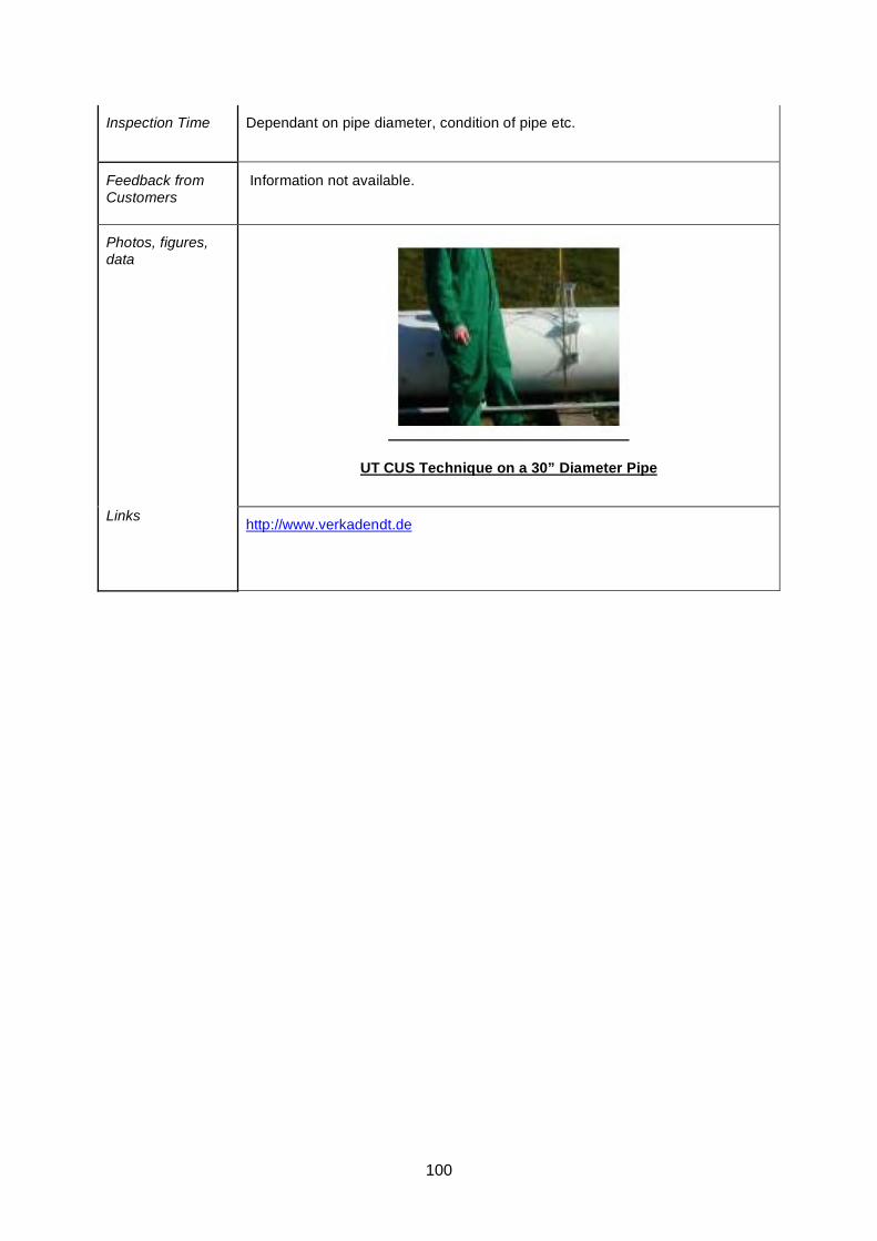
100
Inspection Time Dependant on pipe diameter, condition of pipe etc.
Feedback from Customers
Information not available.
Photos, figures, data
UT CUS Technique on a 30” Diameter Pipe
Links
http://www.verkadendt.de
101
TOFD Fast Screening Technique - Datasheet
Basis of Technique
The method uses regular TOFD equipment as used for inspection of welds. Standard TOFD works well to detect far-side defects in the centre between the probes. To widen the footprint use is made of the mode-conversion waves as well. Shell Global Solutions has dedicated software to estimate the size of the footprint for a certain probe setup, as well as the detection threshold (i.e. a defect response detectable in front of the backwall response) and the sizing accuracy (i.e. the error occurring when the defect location has an offset within the footprint). Also software for automated batch-processing of TOFD scans to measure arrival times of lateral wave, compression and mode-conversion signals from backwall and corrosion defects.
General inspection capabilities
Applicable to components that can also be inspected with regular TOFD (in relation to signal-to-noise characteristics and geometry). The Fast Screening capability is more effective for wall thicknesses above some 20-30 mm, and it can be applied to thicknesses of 100 mm and above.
The footprint varies dependent on the required detection sensitivity; This can be typically:
30 mm wide footprint on a 20 mm WT; 80 mm footprint on a 100 mm WT.
The depth detection threshold will increase with wall thickness (i.e. probe frequency), from typically 0.5 mm on a 20 mm WT, to some 2 mm on a 100 mm WT.
The detection sensitivity can be around 5 mm diameter spherical hole in 20-100 mm WT.
The lateral wave provides a depth-reference of the near surface, which reduces thickness measurement errors related to paint layers.
The method is ideal for detection of small pitting in cladded vessels (of roll bond or explosion bond type; not welded overlay); There is a limitation in total wall thickness in view of the required detection threshold and depth sizing resolution within a 3 mm clad thickness.
Materials include low-alloy carbon steel and higher alloyed materials albeit with a possible reduction in sensitivity (plate material in equi-axed condition, not welded materials).
Operating Temperature
Same as for weld inspection; Continuous scanning up to some 200 ºC is practical; local inspection up to some 450 ºC has been demonstrated recently, but will be limited to smaller areas.
Operator Dependency
Inspection procedure to be developed by competent Level III TOFD engineer, with specific knowledge of TOFD Screening principles (probe optimisation) and with availability of probe optimisation software.
Execution by competent Level II TOFD operator, with specific training in TOFD Screening principles, to ensure sound understanding of detection and measurement capabilities, of calibration procedures, data quality management, and data interpretation.
102
Inspection limitations
Method not so suited for thin wall materials (WT<15-20 mm) due to reduced footprint (reduced advantage over normal beam corrosion mapping systems) and due to lateral wave near surface resolution (WT<6 mm).
TOFD Screening is normally applied with any coating in place; this may give ringing of the lateral wave, which may hamper the detection of defect responses (and may limit the effectiveness of automated processing).
Inclusions in the material may be wrongly interpreted as corrosion pits, especially when they are located close to the backwall.
Access requirements
Dependent on probe deployment different quality access is required for the operator:
- Manual scanning requires comfortable access to the surface for the scan operator.
- Mechanized scanning along a band requires access for applying the band and then putting the scanner on the band (so not necessarily full access is required to the scanned surface).
- Mechanized scanning with remotely operated magnetic-wheel scanner; this would require access from a platform to bring the scanner to the surface, after which it can access all locations on the vessel (out with its dead-zones).
Parameters affecting inspections capabilities
Paint may cause some negative effects. Ringing of the lateral wave may impair detection capability (see limitations above). The sensitivity of the signals may be influenced, positively or negatively, and may need additional dynamic gain control, but the effect may not be detrimental, dependent on the application.
Operator training and certification requirements
TOFD training and certification to level-I, level-II and level-III can be procured from Lavender NDT.
http://www.lavender-ndt.co.uk
Qualifications/trials results/field evidence
Shell Global Solutions has used the technique in the field, on a large, cladded, vessel in a refinery, large diameter pipework, and several large separator vessels.
TOFD detection performance for corrosion defects is based on TOFD’s mature performance reputation;
Fast scanning was demonstrated in the field measurement, achieving 20 m2 in a shift (on vertical vessel wall with comfortable access to vessel wall for manual scan operator).
Figures for the probability of detection (POD) are not available yet.
Commercial availability (product)
This method had been explored by Shell Global Solutions but can be implemented via a number of NDT contractors that have been trained in the technique. The method is not licensed or patented by Shell Global Solutions.
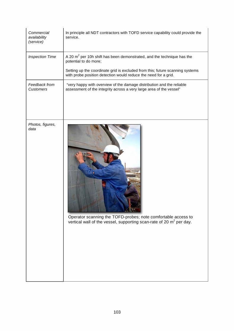
103
Commercial availability (service)
In principle all NDT contractors with TOFD service capability could provide the service.
Inspection Time A 20 m2 per 10h shift has been demonstrated, and the technique has the potential to do more;
Setting up the coordinate grid is excluded from this; future scanning systems with probe position detection would reduce the need for a grid.
Feedback from Customers
“very happy with overview of the damage distribution and the reliable assessment of the integrity across a very large area of the vessel”
Photos, figures, data
1OGEI - Inspection TechnologyShell Global Solutions
TOFD - scanning
Operator scanning the TOFD-probes; note comfortable access to vertical wall of the vessel, supporting scan-rate of 20 m2 per day.
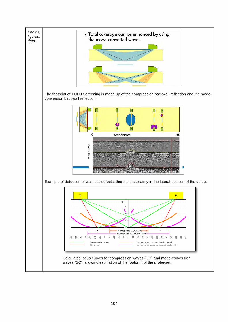
104
Photos, figures, data
The footprint of TOFD Screening is made up of the compression backwall reflection and the mode-conversion backwall reflection
Example of detection of wall loss defects; there is uncertainty in the lateral position of the defect
Calculated locus curves for compression waves (CC) and mode-conversion waves (SC), allowing estimation of the footprint of the probe-set.
2OGEI - Inspection TechnologyShell Global Solutions
0
5
10
15
20
25
-42.0
-38.5
-35.0
-31.5
-28.0
-24.5
-21.0
-17.5
-14.0
-10.5 -7.0
-3.5 0.0 3.5 7.0 10.5
14.0
17.5
21.0
24.5
28.0
31.5
35.0
38.5
42.0
T R
32
1
3
Compression wave
Shear wave Locus curve mode converted backwall
Locus curve compression backwall
Footprint CC-waves
Footprint CC+CS-waves
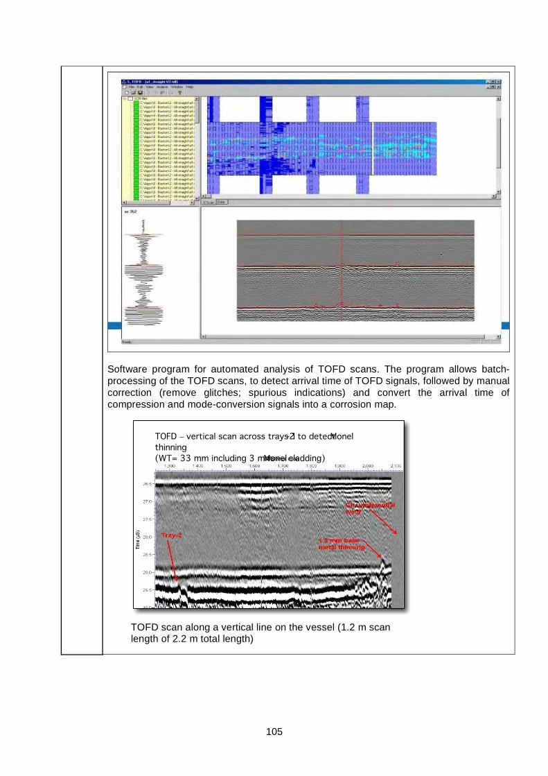
105
Software program for automated analysis of TOFD scans. The program allows batch-processing of the TOFD scans, to detect arrival time of TOFD signals, followed by manual correction (remove glitches; spurious indications) and convert the arrival time of compression and mode-conversion signals into a corrosion map.
TOFD scan along a vertical line on the vessel (1.2 m scan length of 2.2 m total length)
3OGEI - Inspection TechnologyShell Global Solutions
TOFD – vertical scan across trays 1-2 to detect Monelthinning(WT= 33 mm including 3 mm Monel cladding)
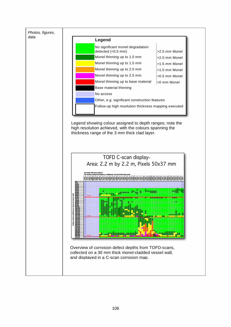
106
Photos, figures, data
Legend showing colour assigned to depth ranges; note the high resolution achieved, with the colours spanning the thickness range of the 3 mm thick clad layer.
4OGEI - Inspection TechnologyShell Global Solutions
LegendNo significant monel degradation detected (<0.5 mm) >2.5 mm MonelMonel thinning up to 1.0 mm >2.0 mm MonelMonel thinning up to 1.5 mm >1.5 mm MonelMonel thinning up to 2.0 mm >1.0 mm MonelMonel thinning up to 2.5 mm >0.5 mm MonelMonel thinning up to base material >0 mm MonelBase material thinning
No access
Other, e.g. significant construction features
Follow-up high resolution thickness mapping executed
5OGEI - Inspection TechnologyShell Global Solutions
TOFD C-scan display –Area: 2.2 m by 2.2 m, Pixels 50x37 mm
8700
8737
.587
7588
12.5
8850
8887
.589
2589
62.5
9000
9037
.590
7591
12.5
9150
9187
.592
2592
62.5
9300
9337
.593
7594
12.5
9450
9487
.595
2595
62.5
9600
9637
.596
7597
12.5
9750
9787
.598
2598
62.5
9900
9937
.599
7510
012.
510
050
1008
7.5
1012
510
162.
510
200
1023
7.5
1027
510
312.
510
350
1038
7.5
1042
510
462.
510
500
1053
7.5
1057
510
612.
510
650
1068
7.5
1072
510
762.
510
800
1083
7.5
1087
50-5050-100100-150150-200200-250250-300300-350350-400400-450450-500500-550550-600600-650650-700700-750750-800800-850850-900900-950950-10001000-10501050-11001100-11501150-12001200-12501250-13001300-1350 1.5 0.9
1350-14001400-14501450-15001500-1550 1.2
1550-1600 1.2
1600-1650 1.2 1.2
1650-1700 1.2 1.2
1700-1750 1 1.2 1.2
1750-1800 0.9 1 1.2 1 1.2
1800-1850 1 1.2 1 1.2
1850-1900 1.1 1 1.2 1 1 1.2
1900-1950 1.2 0.6 1
1950-2000 1 0.6 1.1 1 1.3 1.4
2000-2050 1 0.6 0.6 0.5 1.1 0.2 1.1 -0.3 0.7 0.6
2050-2100 1.4 1.2 1 0.7 0.7 1.2 0.8 1.1 1.3 0.9 0.8 0.8 0.7 1 0.7 0.9 1 0.6 0.6 0.6 0.5 0.7 0.2 1.1 -0.3 -1.8 0.1 0.3 1.5
2100-2150
Area below fifth dome segmentThe numbers indicate the distance, in millimetres, from the North datum point
Hei
ght p
ositi
on (m
illim
etre
s be
low
the
dom
e w
eld)
TrayTray--11
TrayTray--22
TrayTray--33
8700
8737
.587
7588
12.5
8850
8887
.589
2589
62.5
9000
9037
.590
7591
12.5
9150
9187
.592
2592
62.5
9300
9337
.593
7594
12.5
9450
9487
.595
2595
62.5
9600
9637
.596
7597
12.5
9750
9787
.598
2598
62.5
9900
9937
.599
7510
012.
510
050
1008
7.5
1012
510
162.
510
200
1023
7.5
1027
510
312.
510
350
1038
7.5
1042
510
462.
510
500
1053
7.5
1057
510
612.
510
650
1068
7.5
1072
510
762.
510
800
1083
7.5
1087
50-5050-100100-150150-200200-250250-300300-350350-400400-450450-500500-550550-600600-650650-700700-750750-800800-850850-900900-950950-10001000-10501050-11001100-11501150-12001200-12501250-13001300-1350 1.5 0.9
1350-14001400-14501450-15001500-1550 1.2
1550-1600 1.2
1600-1650 1.2 1.2
1650-1700 1.2 1.2
1700-1750 1 1.2 1.2
1750-1800 0.9 1 1.2 1 1.2
1800-1850 1 1.2 1 1.2
1850-1900 1.1 1 1.2 1 1 1.2
1900-1950 1.2 0.6 1
1950-2000 1 0.6 1.1 1 1.3 1.4
2000-2050 1 0.6 0.6 0.5 1.1 0.2 1.1 -0.3 0.7 0.6
2050-2100 1.4 1.2 1 0.7 0.7 1.2 0.8 1.1 1.3 0.9 0.8 0.8 0.7 1 0.7 0.9 1 0.6 0.6 0.6 0.5 0.7 0.2 1.1 -0.3 -1.8 0.1 0.3 1.5
2100-2150
Area below fifth dome segmentThe numbers indicate the distance, in millimetres, from the North datum point
Hei
ght p
ositi
on (m
illim
etre
s be
low
the
dom
e w
eld)
T rayTray --11
TrayTray --22
TrayTray --33
Overview of corrosion defect depths from TOFD-scans, collected on a 30 mm thick monel-cladded vessel wall, and displayed in a C-scan corrosion map.

107
Links HOIS Interactive Knowledge Base
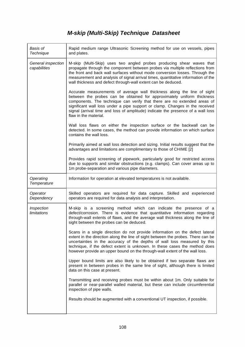
108
M-skip (Multi-Skip) Technique Datasheet
Basis of Technique
Rapid medium range Ultrasonic Screening method for use on vessels, pipes and plates.
General inspection capabilities
M-skip (Multi-Skip) uses two angled probes producing shear waves that propagate through the component between probes via multiple reflections from the front and back wall surfaces without mode conversion losses. Through the measurement and analysis of signal arrival times, quantitative information of the wall thickness and defect through-wall extent can be deduced.
Accurate measurements of average wall thickness along the line of sight between the probes can be obtained for approximately uniform thickness components. The technique can verify that there are no extended areas of significant wall loss under a pipe support or clamp. Changes in the received signal (arrival time and loss of amplitude) indicate the presence of a wall loss flaw in the material.
Wall loss flaws on either the inspection surface or the backwall can be detected. In some cases, the method can provide information on which surface contains the wall loss.
Primarily aimed at wall loss detection and sizing. Initial results suggest that the advantages and limitations are complimentary to those of CHIME [2]
Provides rapid screening of pipework, particularly good for restricted access due to supports and similar obstructions (e.g. clamps). Can cover areas up to 1m probe-separation and various pipe diameters.
Operating Temperature
Information for operation at elevated temperatures is not available.
Operator Dependency
Skilled operators are required for data capture. Skilled and experienced operators are required for data analysis and interpretation.
Inspection limitations
M-skip is a screening method which can indicate the presence of a defect/corrosion. There is evidence that quantitative information regarding through-wall extents of flaws, and the average wall thickness along the line of sight between the probes can be deduced.
Scans in a single direction do not provide information on the defect lateral extent in the direction along the line of sight between the probes. There can be uncertainties in the accuracy of the depths of wall loss measured by this technique, if the defect extent is unknown. In these cases the method does however provide an upper bound on the through-wall extent of the wall loss.
Upper bound limits are also likely to be obtained if two separate flaws are present in between probes in the same line of sight, although there is limited data on this case at present.
Transmitting and receiving probes must be within about 1m. Only suitable for parallel or near-parallel walled material, but these can include circumferential inspection of pipe walls.
Results should be augmented with a conventional UT inspection, if possible.
109
It is recommended that supplementary 0º wall thickness measurements are taken to establish the component wall thickness local to the M-skip probes within a scan, and also along the line of sight between the M-skip probes if access is available (e.g. at scan start and scan end positions for pipe support inspection).
Inspections can be carried out with M-skip probes pointing both axially and circumferentially. Lower angled probes are used when scanning circumferentially, to maintain an approximately constant incident angle on the ID surface.
The presence of coatings can significantly reduce the amplitude and quality of M-skip signals. The severity of this effect increases with the number of internal reflections experienced by the signals, and may depend on coating type.
For thin-walled components (less than about 10mm), isolated pitting flaws can give total loss of signal, and hence no information on flaw through-wall extent. Experience to data suggests that improved flaw sizing information is obtainable for wall thicknesses > 15mm. However, some very irregular, extended areas of wall loss can then also produce a total loss of signal, although this can be minimised by probe optimisation.
Access requirements
Access required to manually attach scanner and probes. Adequate clearance required to manoeuvre scanning jig and probes around the pipe (approx 100mm overhead).
Probe separation must be less than 1m.
Surface condition requirements as for any UT inspection.
M-skip can be applied on curved pipe sections.
Parameters affecting inspections capabilities
Good surface preparation required as with all contact ultrasonic techniques. Good coupling required for transmission of ultrasound – this can be monitored by a separate 0º probe, preferably mounted on the same shoe as the M-skip probe (with common index points).
Changes in transmission signal indicate the presence of a flaw. Signals can be detected and their arrival times measured relative to the skip signals from the reflections off the frontwall/backwall.
Areas of wall loss can also be detected via loss of amplitude of the skip signals.
Operator training and certification requirements
ESR Technology offers training.
Qualifications/trials results/field evidence
M-skip was developed by ESR Technology under the HOIS programme.
On the GSP 236 trial M-skip, when applied with probes pointing circumferentially, the technique provided quantitative wall loss information (subject to some assumptions) and the axial location of any flaws in the pipe. No information was provided on flaw circumferential location. In a separate blind trial the Probability Of Detection (POD) of this method was
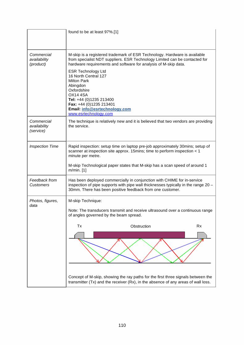
110
found to be at least 97%.[1]
Commercial availability (product)
M-skip is a registered trademark of ESR Technology. Hardware is available from specialist NDT suppliers. ESR Technology Limited can be contacted for hardware requirements and software for analysis of M-skip data.
ESR Technology Ltd 16 North Central 127 Milton Park Abingdon Oxfordshire OX14 4SA Tel: +44 (0)1235 213400 Fax: +44 (0)1235 213401 Email: [email protected] www.esrtechnology.com
Commercial availability (service)
The technique is relatively new and it is believed that two vendors are providing the service.
Inspection Time Rapid inspection: setup time on laptop pre-job approximately 30mins; setup of scanner at inspection site approx. 15mins; time to perform inspection < 1 minute per metre.
M-skip Technological paper states that M-skip has a scan speed of around 1 m/min. [1]
Feedback from Customers
Has been deployed commercially in conjunction with CHIME for in-service inspection of pipe supports with pipe wall thicknesses typically in the range 20 – 30mm. There has been positive feedback from one customer.
Photos, figures, data
M-skip Technique:
Note: The transducers transmit and receive ultrasound over a continuous range of angles governed by the beam spread.
Rx Obstruction Tx
Concept of M-skip, showing the ray paths for the first three signals between the transmitter (Tx) and the receiver (Rx), in the absence of any areas of wall loss.
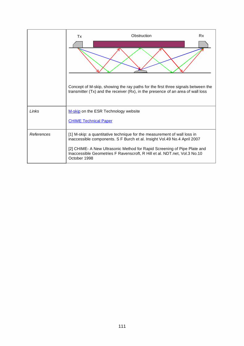
111
Rx Tx Obstruction
Concept of M-skip, showing the ray paths for the first three signals between the transmitter (Tx) and the receiver (Rx), in the presence of an area of wall loss
Links M-skip on the ESR Technology website
CHIME Technical Paper
References [1] M-skip: a quantitative technique for the measurement of wall loss in inaccessible components. S F Burch et al. Insight Vol.49 No.4 April 2007
[2] CHIME- A New Ultrasonic Method for Rapid Screening of Pipe Plate and Inaccessible Geometries F Ravenscroft, R Hill et al. NDT.net, Vol.3 No.10 October 1998
112
Rapidscan Technique Datasheet
Basis of Technique
Ultrasonic testing. Fast and versatile C-scan inspection instrument
General inspection capabilities
* 128 channel Ultrasonic array in wheel probe
* A, B, C, D scan mode
* Mainly detects laminar defects
* Can be used on metals to detect corrosion (hidden, inter-laminar and exfoliation) and to detect cracks.
* Additionally can be used to assess Adhesive bonding and on composites to asses impact damage and de-laminations.
* Additionally can scan for Adhesive bonding, Fibre wrinkling and Porosity.
* Water filled flexible rubber tyre used for array coupling. This have improved surface conformance over standard probes.
* Wheel probe can also be integrated into automated system
Operating Temperature
Ambient temperature
Operator Dependency
Semi-skilled operator could be used for data capture. However, skilled operator is required for technique development, instrument setup and data interpretation.
Inspection limitations
Only large areas suitable for testing.
More suitable for detection of laminar defects in composites.
The cable between detector and probe cannot be longer than 10m so rope-access might prove difficult.
Access requirements
* General equipment weighs 12 kilos and the probe 3kg.
* For large plate surfaces access to allow scanning should not be an issue.
Parameters affecting inspections capabilities
Minimal Coupling required for transmission of ultrasound – thin spray of water.
Flatness of surface normal to scan direction.
The technique is best suited for defects parallel to the scanned surface. Defects oriented differently could be difficult to detect.
Operator training and certification requirements
There is no specific operator training requirement for deployment of this technique. Operators suitably qualified in ultrasonics and familiar with the equipment can be used.
Qualifications/trials results/field evidence
Airbus, a wind energy client and composite manufacturers amongst others have applied Rapidscan.
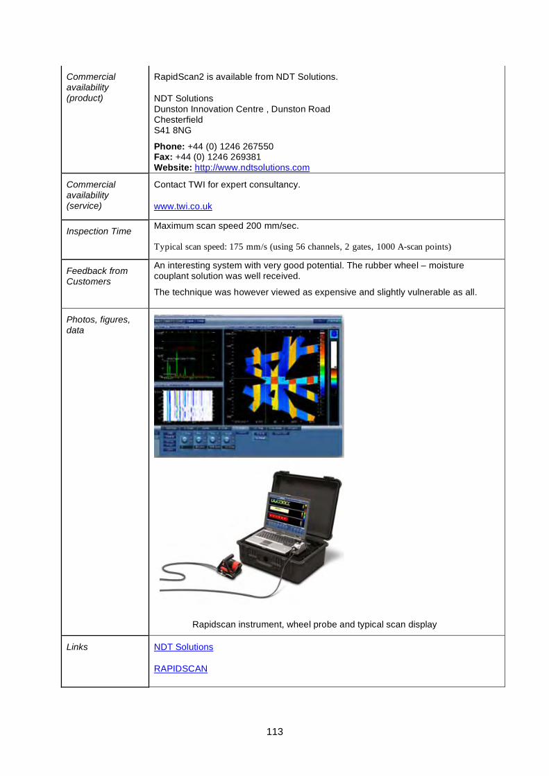
113
Commercial availability (product)
RapidScan2 is available from NDT Solutions.
NDT Solutions Dunston Innovation Centre , Dunston Road Chesterfield S41 8NG
Phone: +44 (0) 1246 267550 Fax: +44 (0) 1246 269381 Website: http://www.ndtsolutions.com
Commercial availability (service)
Contact TWI for expert consultancy.
www.twi.co.uk
Inspection Time Maximum scan speed 200 mm/sec. Typical scan speed: 175 mm/s (using 56 channels, 2 gates, 1000 A-scan points)
Feedback from Customers
An interesting system with very good potential. The rubber wheel – moisture couplant solution was well received.
The technique was however viewed as expensive and slightly vulnerable as all.
Photos, figures, data
Rapidscan instrument, wheel probe and typical scan display
Links NDT Solutions
RAPIDSCAN
114
Acoustic Emission Technique - Datasheet
Basis of Technique
The acoustic emission (AE) technique utilises the detection of high frequency transient elastic waves emanating from a source within a structure which are converted to electrical signals by a surface mounted sensor for subsequent analysis . The source is the material itself and may be the result of localised yielding or cracking of the base material, or of the products resulting from corrosion. AE sensors are also used for leak detection on pressurised systems, signals from leakage are continuous in nature making this is a straightforward application.
The piezoelectric sensor is mounted directly onto the surface of the structure, or, in the case of high temperature structures, on the end of a metal “waveguide” which is attached to the structure, usually by welding.
For detection the source must be active during the monitoring period, which means the structure needs to be stressed or operating. In the case of a short-term test, additional stress is usually applied to the structure to stimulate activity. For pressure vessels this is typically hydrostatic or pneumatic. Where the damage of interest cannot be further stimulated by applying additional stress it may be necessary to monitor for an extended period, or even continuously. Monitoring during start-up or cool-down where major thermal stress occurs may be more appropriate for thick-wall high temperature plant.
The signal from the sensors is amplified using a low noise preamplifier, which also filters the signal and provides a line drive for long cables, in most instances the pre-amplification, filtering, line-drive, and a self-test pulse function is inside the sensor itself. The signal is further processed and then digitised by the AE system which extracts signal “features” and has software for identification and removal of extraneous noise, and graphing of the results. Relevant parameters such as pressure and strain are also measured and recorded by the AE system for correlation with the AE activity. AE systems are usually based around specialist PCI boards with digital signal processing, installed in an industrial PC or specialist chassis running PC software.
The AE method, which is effectively seismology on a small scale, also locates the source of any emissions that reach multiple sensors by measuring the relative time arrival and carrying out “triangulation”. Location may be linear, two, or three dimensional, depending upon the sensor configuration. Advanced analysis methods used on the raw waveform are sometimes used to learn more about the source and its transmission path, on plated structures it is possible for example to establish the distance to source from a single waveform by analysis of the wave modes.
General inspection capabilities
The acoustic emission technique can be used to monitor defects which are active under the test conditions.
• Monitoring can take place from a number of locations whilst the plant is still in operation.
• Can detect faults or leakages in pressure vessels, tanks, and piping systems.
• AE is a non-invasive technique.
• Minimal disturbance to vessel or pipe insulation.
• Gives an immediate indication of the response and behaviour of the
115
material under stress pertaining to factors such as strength, damage and failure.
• Can be used for online monitoring of welding, corrosion and plant integrity on a permanent basis.
• Studies have shown that AE is capable of detecting and distinguishing between different stages of corrosion in atmospheric tank floors.
• Highly sensitive method of testing which is also intrinsically safe.
• Compared to other NDT techniques, acoustic emission detects activity from inside the material itself as opposed to sending and then detecting some form of energy.
• Detection of inner- outer- and embedded defects
• Not affected by defect orientation, however the defect must be active under test conditions
Main codes relevant to PV testing are given below:
• ASME: V article 12 (AE on metallic vessels), V article 11 (AE on fibre reinforced vessels), V article 13 (continuous acoustic emission monitoring).
• ASTM: E1419-02 (AE testing of seamless gas bottles), E1139-02 (AE continuous monitoring), E1067-01 (AE testing of FRP vessels)
• BS EN 14584, BS EN 15495:2007 (AE testing of metal vessels)
Operating Temperature
Sensors are available for use to 550 deg.C, and waveguides can be used at any temperature.
Operator Dependency
High – specialist technique. Data interpretation requires skilled personnel, however there are a number of “standard” procedures and codes that are highly developed which reduces the need for expert interpretation, these include aerial device testing, and fibreglass tanks.
Inspection limitations
• AE relies on growth activity of the defect for detection.
• AE techniques only provide a qualitative assessment; other NDT methods are required to produce quantitative assessments, i.e. AE gives defect activity, follow-up NDT is required to give defect size. The use of AE to “direct” NDT makes the NDT inspection more effective, by allowing it to focus on known problem areas.
• Susceptibility to signal to noise (S/N) issues when AE is utilised in “noisy” environments. Due to the AE signals being very weak, a high level of signal processing is required to correct this. Background noise can be generated by process activities etc. and background noise can also prevent any conclusive data from being acquired.
116
Access requirements
• Once sensors are in place monitoring can be carried out on line, beneficial in noisy or harsh environments.
• Detection range of transducer from 0.5 to 10 meters (1.5 to 33ft) – Range is dependant on in-service process noise levels, and the frequency of the sensor used for monitoring.
• Distance between measurement points vary depending on the application in hand; i.e. 1.) ~5 meters (15 feet) in high stress zones 2.) ~3 meters (10 feet) in main steam lines 3.) ~2.5 meters (8 feet) in cold reheat lines. (Values given are typical values.)
Parameters affecting inspections capabilities
• Background noise issues within the plant, (not usually airborne noise but signals travelling in the structural material).
• Material attenuation which can involve the plant absorbing some or all of the signal, unless already known the attenuation at the monitoring frequency being used is usually measured before commencing sensor installation.
Operator training and certification requirements
PCN qualifications (Level 1-3) are available, as are ASNT, COFREND, DGZFP, ABENDE.
Qualifications/trials results/field evidence
MONPAC procedure – well documented, per the Institute of Chemical Engineers International process safety working group this is the “de-facto industry standard” for in-service metal vessels.
ASME standards – Many standards and exemptions on use of AE. ASME code Edition 2001, Sec V-Article 1, Page 15.2, Table A-110, NDT Method Recommendation gives POD for cracking using AE at 80-100%.
API 581 effectiveness of AE on cracking 1-3
There is currently an HSE project under way to investigate the capabilities of Acoustic Emission.
Commercial availability (product)
• Physical Acoustics Ltd (PAL) produces many AE instruments. • Vallen Systeme (Germany) is also a producer of AE equipment. • The Vigilant AE System for structural health monitoring is available from
Ultra Electronics Ltd.
Physical Acoustics Corp. 195 Clarksville Road Princeton Jct, NJ 08550 USA Tel: +1 609.716.4000 Fax: +1 609.716.0706 E-mail: [email protected]
Tel: +44 (0)1954 231612 Fax: +44 (0)1954 231102 E-mail: [email protected]
Website: http://www.pacndt.com
http://www.pacuk.co.uk
Vallen-Systeme GmbH PO-Box 34 82055 Icking, Munich, Germany Tel: +49-8178-9674-400 Fax: +49-8178-9674-444 E-mail: [email protected] Website: http://www.vallen.de
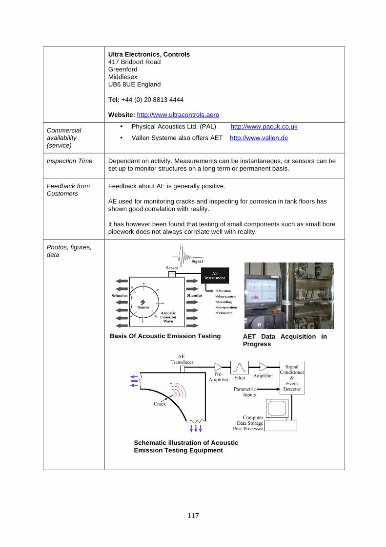
117
Ultra Electronics, Controls 417 Bridport Road Greenford Middlesex UB6 8UE England
Tel: +44 (0) 20 8813 4444
Website: http://www.ultracontrols.aero
Commercial availability (service)
• Physical Acoustics Ltd. (PAL) http://www.pacuk.co.uk
• Vallen Systeme also offers AET http://www.vallen.de
Inspection Time Dependant on activity. Measurements can be instantaneous, or sensors can be set up to monitor structures on a long term or permanent basis.
Feedback from Customers
Feedback about AE is generally positive.
AE used for monitoring cracks and inspecting for corrosion in tank floors has shown good correlation with reality.
It has however been found that testing of small components such as small bore pipework does not always correlate well with reality.
Photos, figures, data
Basis Of Acoustic Emission Testing
AET Data Acquisition in Progress
Schematic illustration of Acoustic Emission Testing Equipment

118
Links http://www.pacndt.com/
http://www.pacuk.co.uk/
119
Quantitative Acoustic Emission Technique - Datasheet
Basis of Technique
All acoustic emission techniques (AE) aim for the detection and conversion of high frequency elastic waves emanating from a source to electrical signals. The elastic waves are generated when there is a re-distribution of stress in a material such as deformation or crack growth. The elastic waves are sound and ultrasound waves and are referred to as (AE) signals.
There are two major types of AE signals: burst (impulse) and continuous signals. Continuous AE signals are associated with processes related to plastic deformation development around flaws. The greater the volume of material involved in the process the higher the energy of AE signals.
Burst AE is associated with flaw elongation such as slip and dislocation movement, growth of cracks, twinning and phase transformations in metals.
Once generated, the elastic waves will subsequently propagate to the surface where suitably mounted AE sensors will detect and record the waves. The resultant signals from the sensors are then amplified using a pre-amplifier before being analysed.
Conventional AE only analyses the burst signals whilst QAE analyses both continuous and burst signals. This is a great drawback for conventional AE, for example in the case of silent cracks, the energy surrounding the crack absorbs the sound and will not be detected. This means that the QAE method is able to provide much more information about the component.
The QAE approach involves determination of the J-Integral value (the path integral around a crack tip representing the energy released per unit area). Information such as flaw location, crack kinetics and stress concentration can be detected.
It should be noted that QAE does not measure defect size, but detects stress displacement such as growth of defects or incorrectly loaded areas of pipework.
Detecting stress concentrations and over stressed zones can also be useful for assessing the condition of hangers and supports. A remnant life estimate and strategy for future inspection frequencies can also be decided from the output from QAE.
Hence, as with conventional AE, QAE provides a means to more targeted NDT. There may also be commercial and health & safety savings in that there is a reduced requirement for scaffold and insulation removal/replacement.
General inspection capabilities
• Early detection of inner, outer and embedded flaws of the structure, including cracks and stress concentrations
• Inspection during plant operation, without shut down
• Ability to predict remnant life of the component
• The ability to detect and monitor stress corrosion cracking (SCC) and very early stages of creep.
• Full inspection coverage of component.
• Is also able to detect uneven stresses placed on the component such as problems with hanger and support designs.
120
Operating Temperature
The QAE equipment does not suffer from any upper temperature limitations as known to date. The cables used in the installation are capable of operating up to 120°C. Air temperatures outside the insulation very rarely reach those temperatures in a conventional power plant and it is therefore not viewed as a limitation.
Operator Dependency
Skilled operators are required for data capture. Data analysis and interpretation is done by the researchers.
Inspection limitations
• Will only detect “active” defects (stagnant defects do not induce stress concentrations).
• Conventional NDT or metallurgical investigations are necessary to establish defect sizes.
• The method is not a continuous on-line monitoring method. After equipment is installed, the frequency of screening/monitoring of the component will be agreed with the client.
Access requirements
• Full access is required during instalment of equipment. Installation is normally carried out whilst the plant is still online. Generally this is performed using rope-access to remove the need for scaffolding.
• No access to the component is required during inspection unless equipment is damaged.
Parameters affecting inspections capabilities
The flaws will need to be in a state where stress concentrations are present around them to be detected. A flaw that is not growing or inducing any increased stresses will not be found. Non-developing flaws are however generally not of concern so using QAE can prevent wasted inspection resource on non-critical defects.
Operator training and certification requirements
Independent training is not available. Margan own the IP and provide operator training. Data analysis is carried out by the researchers who originally developed the technique.
The personnel installing the equipment have prior experience in similar installation procedures and have in addition received informal training from Margan.
The equipment used is standard AE equipment and the equipment manufacturer is operating in accordance with quality system ISO 9001:2000 and holds a UKAS accreditation.
Qualifications/trials results/field evidence
VGB co-ordinated a project to verify QAE, mainly by correlation between QAE and conventional inspection methods such as surface replication and TOFD ultrasonics to assess its potential.
QAE produced results that indicated that it could be used as an integral monitoring system. Creep damage was found and proven in several places.
There was however no direct correlation between the QAE technology and the VGB creep classification. This was due to the fact that the techniques are based on different theoretical concepts (J-integral for QAE) and also serve different objectives.
TÜF NORD
The QAE technique was appraised by TÜV NORD in April 2005.
The TÜV recommendations were similar to those of VGB. It was found that Margan's
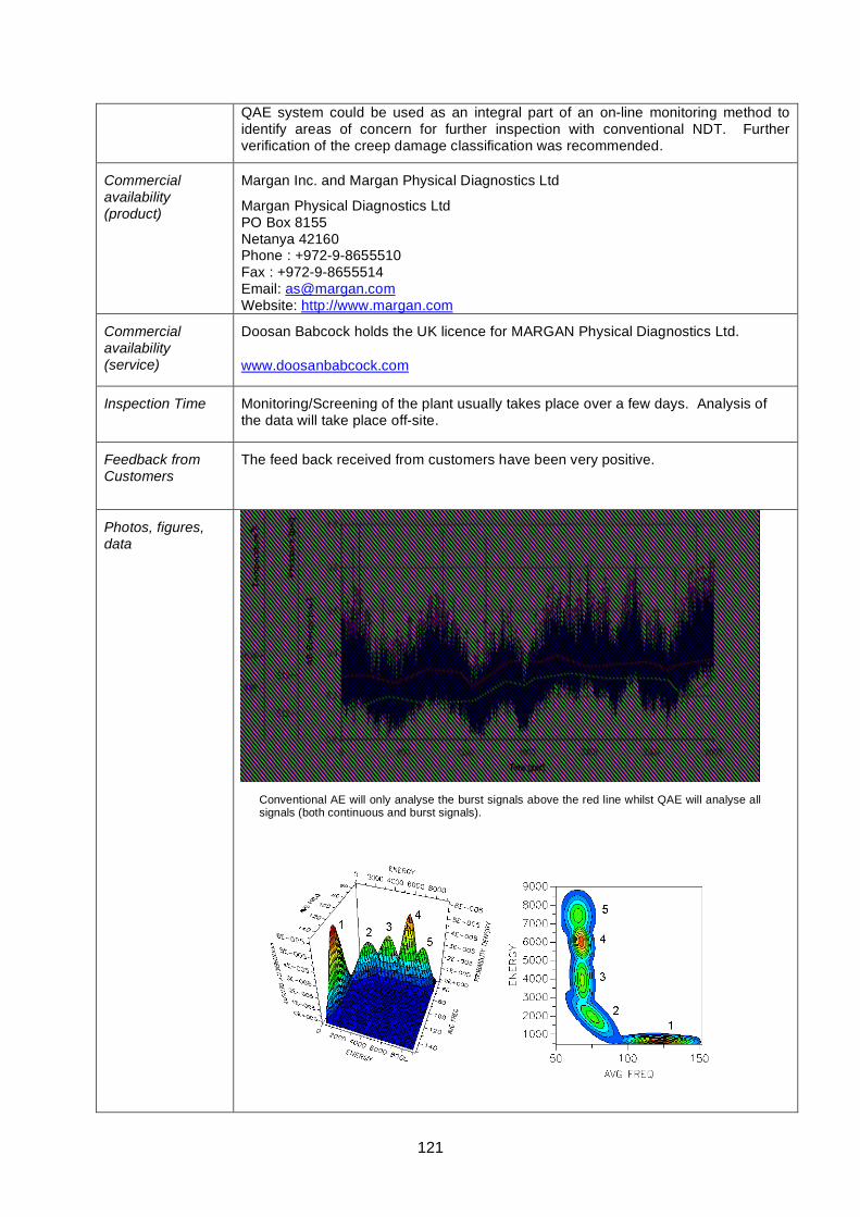
121
Conventional AE will only analyse the burst signals above the red line whilst QAE will analyse all signals (both continuous and burst signals).
QAE system could be used as an integral part of an on-line monitoring method to identify areas of concern for further inspection with conventional NDT. Further verification of the creep damage classification was recommended.
Commercial availability (product)
Margan Inc. and Margan Physical Diagnostics Ltd
Margan Physical Diagnostics Ltd PO Box 8155 Netanya 42160 Phone : +972-9-8655510 Fax : +972-9-8655514 Email: [email protected] Website: http://www.margan.com
Commercial availability (service)
Doosan Babcock holds the UK licence for MARGAN Physical Diagnostics Ltd.
www.doosanbabcock.com
Inspection Time Monitoring/Screening of the plant usually takes place over a few days. Analysis of the data will take place off-site.
Feedback from Customers
The feed back received from customers have been very positive.
Photos, figures, data
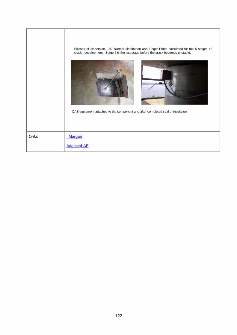
122
Links Margan
Adanced AE
Ellipses of dispersion. 3D Normal distribution and Finger Prints calculated for the 5 stages of crack development. Stage 5 is the last stage before the crack becomes unstable.
QAE equipment attached to the component and after completed seal of insulation
123
Lixi Technique - Datasheet
Basis of Method Real time radiographic equipment for screening for corrosion in pipes. Main applications are CUI and corrosion under coatings in addition to locating blockage in process piping. The technique involves a Gadolinium-153 isotope mounted on one side of a C-arm scanner and a detector on the opposite side.
Lixi, Inc. offers three products for this type of application: the Profiler, the Gadscope, and the Penetrator.
Lixi Profiler The radiation beam is directed through the centre of the pipe measuring the double wall thickness. Data is presented in the form of a graph. The graph is produced instantly (in real time) and presented electronically on a computer (rather than on film). The scanner is moved along the length of pipe and each line scan measures the double wall thickness for a discreet section. For horizontal pipe the normal procedure is to perform 3 line scans measuring sections at 12 o’clock (0º)/6o’clock (180º), 45º /225º, 135º /315º (although this will depend on the pipe process and where corrosion is expected).
Lixi Gadscope & The Lixi Penetrator The Lixi Gadscope uses a radioisotope of Gd-153 as the radiation source. The Lixi Penetrator uses an x-ray tube as the radiation source. In either system, the radiation beam is aimed tangentially so that it can real-time image the outer surface profile of the pipe at a given location (normally the 6 o’clock position on horizontal pipes) as well as features within the insulation. The Gadscope would be more appropriate than the Profiler for larger diameter pipework containing dense product. It provides a qualitative result but could be used to complement the more quantitative Profiler when it’s important to confirm whether corrosion is on the outer surface or not.
General inspection capabilities
The Profiler enables inspections on material thicknesses up to 50mm total thickness (25mm single-wall thickness) for steel.
Using a low radiation source restricts the penetration capability of the energy but allows the operator to work without cordoning off any areas and can be deployed by rope access. For the Profiler, the absolute maximum thickness of steel the energy can penetrate is 50mm and by 33mm it is may be hard to identify shallow defects and confidence is reduced. The double wall thickness measured when inspecting pipe thicknesses using the system therefore results in a maximum pipe wall thickness of 19mm.
The Lixi Profiler measures loss of wall thickness and can detect changes from 1-3mm depending on material thickness. The technique can also detect the location of weld caps or blockages within the pipe
Real time measurements meaning that it is relatively rapid.
The new version of the Lixi Profiler allows for inspection data to be “tagged” on the computer and a corresponding tag number may be inscribed on the pipe for matching defect location. Inspection data may be viewed on any spreadsheet program and even charted to view entire sessions at one time. The new Profiler incorporates software facilities to enhance the operator's ability to identify potential areas of concern and make it easier to analyze results in real-time.
124
Operating Temperature
Non-contact so temperature not normally a limiting factor.
Operator Dependency
High. Relatively easy to learn to deploy scanner and collect data but operator needs to be able to able distinguish between wall thickness variations and natural pipe features. Skilled deployment is required to ensure the beam is directed through the centre of the pipe when using the Profiler.
Inspection limitations
Lixi Profiler C-scanner comes in three standard sizes: 6”, 13” and 18”.
Lixi Gadscope standard arm opening is 24”.
The absolute absorption of radiation by an object depends upon the thickness, density (porosity) and the atomic number of the elements present in the material
No encoder is used to position the defects. This means that defect positions are not recorded by the system, but may be recorded by the operator on the insulation jacket at the time of inspection.
In common with conventional radiography, poor detection capability for narrow cracks and small isolated pits.
Access restrictions and component geometry limitations are restricted by the design of the equipment.
Isotopes are governed by the Ionising Radiations regulations.
Access from opposite sides of the component is fundamental as the inspection data generated is based on the amount of radiation that has passed through the component
Unable to distinguish between inner or outer surface corrosion. Possible to discern between upper or lower wall thinning with an additional “slice” scan made perpendicular to the defect location.
Measurement may be affected when corrosion product is present. The lower density of loose corrosion product makes associated wall loss detectable although over-measurement is possible. Well-adhering corrosion product may not be detectable.
Access requirements
Equipment needs to be in close proximity to the component. For Profiler using a low radiation source this can be done via rope access. Access to the component can be restricted by the C-arm as access is needed from two sides of a pipe to gain measurements.
Parameters affecting inspections capabilities
Care should be taken to ensure the Profiler is held at a right angle or too high a thickness might be reported due to chord length effects. This can also appear when the insulation jacket of an insulated pipe is not located concentrically over the pipe and care must be taken not to report too high a wall thickness
Operator training and certification requirements
No formal certification available. Lixi, Inc. provides training.
125
Qualifications/trials results/field evidence
It takes approximately two months for an operator to become confident and to accurately analyse data. Training can be provided by Gamma graphics or Lixi.
There are no field / trial evidence on CUI inspection using Lixi profiler to date.
CRIS PoD trials have demonstrated that the LIXI profiler penetrates at least 28 mm of steel (information from the HOIS Interactive Knowledge Base). As shown in the CRIS PoD trials, the Profiler was the only technique to approach the “ideal” NDT technique by delivering the highest PoD (96%) and lowest false call rate of any of the techniques tested.
Commercial availability (product)
Lixi, Inc 11980 Oak Creek Parkway Huntley ILLINOIS 60142 USA
Tel. USA 847 961 6666
Commercial availability (service)
Gamma Graphics is a wholly owned subsidiary of Lixi, Inc. which provides the Lixi service business.
N.B. Gamma Graphics UK no longer own the exclusive licence for the Lixi Profiler in the UK. It is understood that they do still offer the service but not on an exclusive basis.
Service is coordinated by Lixi, Inc. – contact details above.
Inspection Time On average 150m (pipe length) a day.
Feedback from Customers
Lixi has had mixed reviews in the UK. Negative feedback is mainly attributable to poor quality of deployment, rather than any weakness in the technology. Logically good feedback has been obtained where the technique is applied more reliably.
There is an apparent lack of qualified procedures and personnel in the UK.
The technology has been found to be very operator dependant. Results are presented without any refrence to defect location, this makes it very hard to benefit from the defects found if the results are presented off site. It also makes it impossible to go back and repeat inspections.
The technique could benefit from developing and following a procedure. This could include scan locations to ensure that scans can be repeated. Status of pipe such as if it is insulated or uninsulated, what type of pipe content is present. This will help the client to benefit from the results provided as they are all dependant .
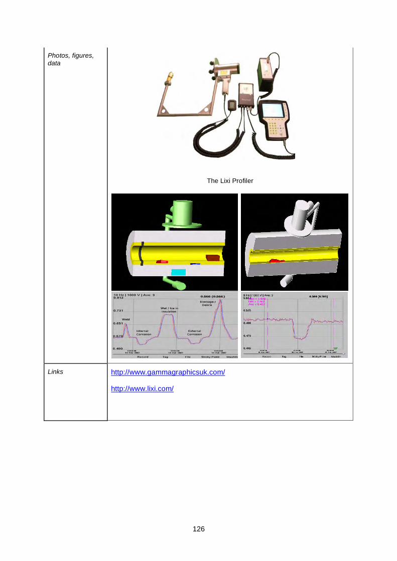
126
Photos, figures, data
The Lixi Profiler
Links http://www.gammagraphicsuk.com/
http://www.lixi.com/
127
SCAR Technique Datasheet
Basis of Technique
SCAR, Small Controlled Area Radiography, is a (conventional) radiographic tool utilising collimated either 500 Gbq, Iridium 192 or a Selenium 75 isotope.
The radiation beam is reduced to an area needed to still produce a useful radiograph. Depleted Uranium encased by a steel container holds the source and shields it from its environment; it also acts as a collimator when the source is in the exposed position. This is permitting the use of a very small exclusion zone of only 2-5 metres around the isotope and reduces dose rates for the inspection personel.
General inspection capabilities
The small exclusion zone is significantly less than for traditional radiography systems and considerably lowers the H&S risks that are associated with using radiography. When the source is in the exposed position will the radiation be collimated through a cylinder ending in a pyramidial porthole, allowing the nescessary amount of radiation egress. The escaping beam is therefore heavily directed with litle spread and is relatively easy to attenuate.
Conventional radiography can command exclusion zones of over 100m whilst the SCAR system can work in exclusion zones of as low as 3 meters.
The isotope never leaves the container and is hence designed to be completely fail-safe. The source is ejected from the stored position into the collimator using pneumatics pressing against a return spring. In the event of failure of the pneumatics the source will be reutrned automatically to the stored position by the retun spring. The system is also intrinsically safe.
Clamps and asscesories have been constructed for SCAR to fit pipe diameters between 10-2000mm
The method itself is not rapid but vast overall time savings can be achieved through the significantly reduced exclusion zone.
Operating Temperature
Operation at ambient temperature. Information not available for operation at elevated temperatures.
Operator Dependency
Yes.
Inspection limitations
Normally slower to deploy than conventional radiography
Clearance around pipe for mounting film / digital system.
Set up time.
Access requirements
Full access is needed to the component to set up the equipment. The method benefits from lending itself to rope access if needed.
Parameters affecting inspections
Limitations in terms of how thick materials that can be inspected are governed by the type of source utilised.
128
capabilities Radiography will not detect narrow cracks and small isolated pits.
Although a greatly reduced amount of ionising radiation will enter the enviorment, appropriate meassures still needs to be taken to ensure compliance with Health & Safety legislations.
Access from more than one side of the component is fundamental as the inspection data generated is based on the amount of radiation that has passed through the component.
Qualifications/trials results/field evidence
Information not available.
Commercial availability (product)
SCAR can be procured from Oceaneering Inspection
http://www.oceaneering.com
SafeRad, similar to SCAR, is available from:
SafeRad
6 Stockley Grove Brancepeth County Durham DH7 8DU Phone 00-44-191-3782130 Fax 00-44-191-3782130 E-mail: [email protected]
Website : http://www.saferad.com
Commercial availability (service)
Oceaneering : http://www.oceaneering.com/inspection.asp?id=962
SafeRad : http://www.saferad.com
http://www.mbinspection.co.uk/index/saferad
Inspection Time The SCAR system can be used on a continual 24 hour basis as no large areas need to be cleared for its use meaning other work can go on uninterrupted. If used in conjunction with digital or computerised films great timesavings can be made.
Feedback from Customers
Information not available.
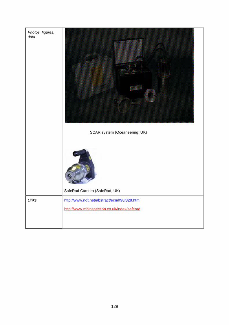
129
Photos, figures, data
SCAR system (Oceaneering, UK)
SafeRad Camera (SafeRad, UK)
Links http://www.ndt.net/abstract/ecndt98/328.htm
http://www.mbinspection.co.uk/index/saferad
130
ThruVu Technique Datasheet
Basis of Technique
Direct digital gamma radiography using collimated source and linear array of solid-state sensors. Special software gives on-line display of wall thickness.
General inspection capabilities
A two-dimensional image is displayed, whose intensity is proportional to the wall thickness, thus indicating corrosion and/or erosion on both outside and inside walls.
Can be used to inspect insulated and uninsulated pipework of 6” to 36” diameter.
Operating Temperature
Ambient temperature.
Operator Dependency
Yes.
Inspection limitations
Basic system designed for horizontal pipelines. A rail-mounted system has been developed which can be used on horizontal or vertical pipework and elbows.
The length of the delivery tube on the source container dictates the maximum length that can be covered in a single scan. This is normally of the order of 6m (20').
Although source is collimated, radiation exclusion zone is still required.
Dead zone at each pipe support; the pipe can be examined to within 50mm of the support on the leading edge but only to within 150mm on the trailing edge.
Access requirements
Low intensity Ir 192 isotope sits on one side of the pipe with an array of solid state detectors situated on the other.
Rail-mounted system requires minimum clearance of 300mm on the source side of the pipe, 100mm on the opposite (detector) side, and 25mm lateral clearance.
Access is required at some location on the pipe to mount the rails and attach the detector.
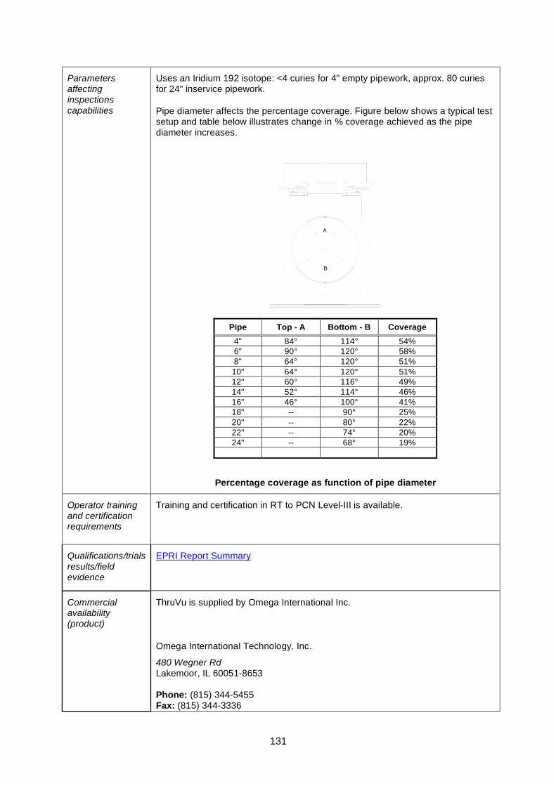
131
Parameters affecting inspections capabilities
Uses an Iridium 192 isotope: <4 curies for 4" empty pipework, approx. 80 curies for 24" inservice pipework.
Pipe diameter affects the percentage coverage. Figure below shows a typical test setup and table below illustrates change in % coverage achieved as the pipe diameter increases.
A
B
Percentage coverage as function of pipe diameter
Pipe Top - A Bottom - B Coverage 4" 84° 114° 54% 6" 90° 120° 58% 8" 64° 120° 51% 10" 64° 120° 51% 12" 60° 116° 49% 14" 52° 114° 46% 16" 46° 100° 41% 18" -- 90° 25% 20" -- 80° 22% 22" -- 74° 20% 24" -- 68° 19%
Operator training and certification requirements
Training and certification in RT to PCN Level-III is available.
Qualifications/trials results/field evidence
EPRI Report Summary
Commercial availability (product)
ThruVu is supplied by Omega International Inc.
Omega International Technology, Inc.
480 Wegner Rd Lakemoor, IL 60051-8653 Phone: (815) 344-5455 Fax: (815) 344-3336
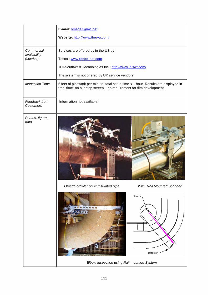
132
E-mail: [email protected]
Website: http://www.thruvu.com/
Commercial availability (service)
Services are offered by in the US by
Tesco : www.tesco-ndt.com
IHI-Southwest Technologies Inc.: http://www.ihiswt.com/
The system is not offered by UK service vendors.
Inspection Time 5 feet of pipework per minute; total setup time < 1 hour. Results are displayed in “real time” on a laptop screen – no requirement for film development.
Feedback from Customers
Information not available.
Photos, figures, data
Omega crawler on 4" insulated pipe ISwT Rail Mounted Scanner
Source
Detector
Elbow Inspection using Rail-mounted System
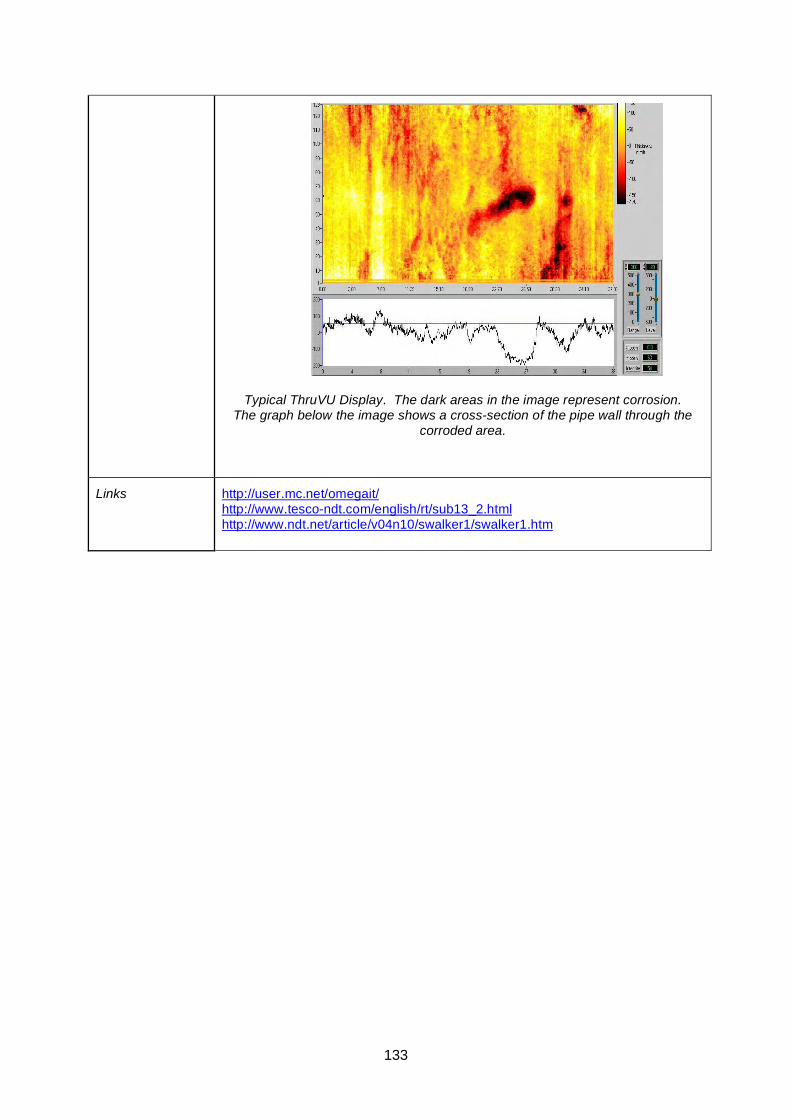
133
Typical ThruVU Display. The dark areas in the image represent corrosion. The graph below the image shows a cross-section of the pipe wall through the
corroded area.
Links http://user.mc.net/omegait/ http://www.tesco-ndt.com/english/rt/sub13_2.html http://www.ndt.net/article/v04n10/swalker1/swalker1.htm

134
Neutron Backscatter Technique - Datasheet
Basis of Technique
A survey method where water content (or more specifically hydrogen content) is established by neutron backscatter.
A radioactive source (Am 241/Be or Cf 252) emits high energy neutrons into the insulation. The neutrons are slowed down or "moderated" by collisions with light elements, in particular hydrogen. They then diffuse back to a thermal neutron detector where the slow neutrons are counted. Moisture in, for example, insulation increases the density of hydrogen nuclei so the number of slow neutrons detected will rise.
General inspection capabilities
Detects moisture under thermal insulation on pipework or vessels. Detection method also works on metal clad insulation. Effective moisture detection capability even where insulation is several centimetres thick.
Hand operated instrument giving on-line readout of results within a few seconds for each location. Detector is sensitive to presence of hydrogen so can be used to detect presence of oil and other liquids with a high hydrogen content.
Detector is very sensitive to water very close and almost completely insensitive to the presence of water farther away. This means that any water within the pipe or vessel will not effect the results. This claim is made by FORCE’s Moisture Probe only.
Operating Temperature
Ambient to 66 ºC. (95% humidity).
Operator Dependency
Specialist operators are required for equipment setup, data capture and interpretation.
Relevance to the components and materials of interest to GSP 236?
Generally suited for use on insulated metal pipework and vessels in petrochemical type environment.
Inspection limitations
• Specialist training is required to operate instrument.
• Not suited for outdoors use during rainfall.
• Needs section of “dry” insulation to calibrate instrument.
• Not suited for use on foam insulation and plastic cladding or any insulation with high hydrogen content.
• Sensitivity drops very steeply after approximately 50 mm. Therefore has reduced capability for very thick insulation.
• Radiological hazards associated with use of neutron source.
Access requirements
Need access to outer surface of insulation or cladding.
Equipment is hand portable so can be used where access is limited. Detector head can be mounted on extension arm if required.
135
Parameters affecting inspections capabilities
• Hydrogen content of insulation material.
• Insulation material thickness.
• Weather at outdoor installations.
Operator training and certification requirements
Basic radiation safety training.
Manufacturers training.
Technicians to be “Classified radiation worker”.
Qualifications/trials results/field evidence
CPN International lnc and FORCE Technology describe effectiveness of their own systems.
No known independent trials.
Other Information The neutron source used in the MCM-2 Hydrotector is 1.85 Giga Becquerel 50mCi Americium-241/Beryllium.
The neutron source used in the FORCE moisture probe is 2 Mega Becquerel 54µCi Californium – 252.
Commercial availability (product)
Two systems available commercially:
MCM-2 Hydrotector from CPN International lnc
CPN International lnc 4057 PORT CHICAGO HIGHWAY SUITE 100 CONCORD, CA 94520 Tel: 925-363-9770 Fax: 925-363-9385
Website: http://www.cpn-intl.com
“Moisture Probe” from FORCE Technology.
FORCE Technology Park Alle 345 2605 Brondby Denmark Tel: +45-43-26-70-00 Fax: +45-43-26-70-11 E-mail: [email protected] Web: www.force.dk
Commercial availability (service)
MCM-2 Hydrotector is available from:
CAN Offshore Ltd Unit 9, Forties Industrial Centre Hareness Circle Altens, Aberdeen, AB12 3LY Tel: (01224) 871 015 Fax: (01224) 876 015 / (01224) 877 015 Email: [email protected]
ELE International Ltd Chartmoor Road Chartwell Business Park Leighton Buzzard, Bedfordshire, LU7 4WG Tel: +44-1-525-249-200 Fax: +44-1-525-249-249 E-mail: [email protected]
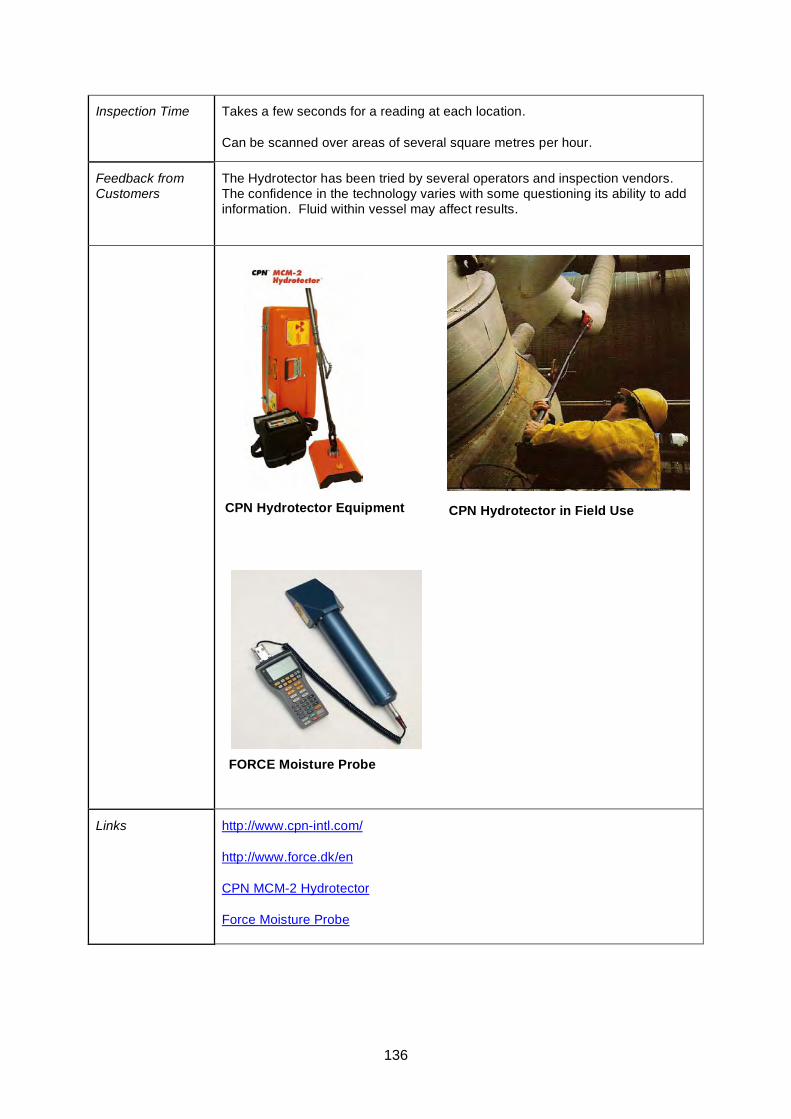
136
Inspection Time Takes a few seconds for a reading at each location.
Can be scanned over areas of several square metres per hour.
Feedback from Customers
The Hydrotector has been tried by several operators and inspection vendors. The confidence in the technology varies with some questioning its ability to add information. Fluid within vessel may affect results.
Links http://www.cpn-intl.com/
http://www.force.dk/en
CPN MCM-2 Hydrotector
Force Moisture Probe
CPN Hydrotector in Field Use CPN Hydrotector Equipment
FORCE Moisture Probe
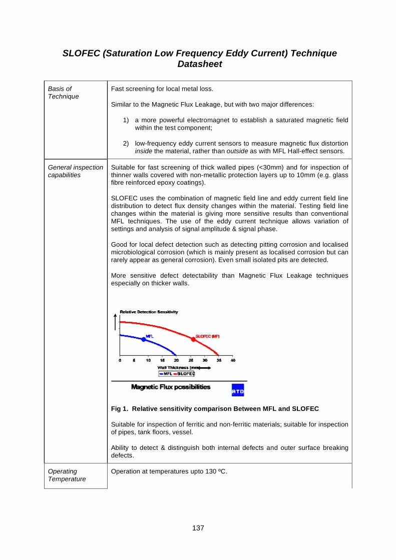
137
SLOFEC (Saturation Low Frequency Eddy Current) Technique Datasheet
Basis of Technique
Fast screening for local metal loss.
Similar to the Magnetic Flux Leakage, but with two major differences:
1) a more powerful electromagnet to establish a saturated magnetic field within the test component;
2) low-frequency eddy current sensors to measure magnetic flux distortion inside the material, rather than outside as with MFL Hall-effect sensors.
General inspection capabilities
Suitable for fast screening of thick walled pipes (<30mm) and for inspection of thinner walls covered with non-metallic protection layers up to 10mm (e.g. glass fibre reinforced epoxy coatings).
SLOFEC uses the combination of magnetic field line and eddy current field line distribution to detect flux density changes within the material. Testing field line changes within the material is giving more sensitive results than conventional MFL techniques. The use of the eddy current technique allows variation of settings and analysis of signal amplitude & signal phase.
Good for local defect detection such as detecting pitting corrosion and localised microbiological corrosion (which is mainly present as localised corrosion but can rarely appear as general corrosion). Even small isolated pits are detected.
More sensitive defect detectability than Magnetic Flux Leakage techniques especially on thicker walls.
Fig 1. Relative sensitivity comparison Between MFL and SLOFEC
Suitable for inspection of ferritic and non-ferritic materials; suitable for inspection of pipes, tank floors, vessel.
Ability to detect & distinguish both internal defects and outer surface breaking defects.
Operating Temperature
Operation at temperatures upto 130 ºC.
138
Operator Dependency
As with MFL, operator expertise is required for data acquisition and interpretation.
Inspection limitations
Tankfloors, vessels and drums: wall thickness up to 30 mm, coatings up to 10 mm.
Pipes and pipelines (1”+ diameter): wall thickness up to 25 mm, coatings up to 7 mm.
(Values taken from Innospection website.)
Sensitive for corrosion detection but not used for absolute wall thickness determination
“Gradual” defects (greater than 300-400mm in length) are not as easily detectable.
Findings should be complemented by conventional ultrasonic inspection.
Access requirements
Sensors attached to a scanner for pipe inspections. Dimensions OD from 1inch to flat, Wall thickness range from 0 to 26mm (max field experience 33mm)
PipeScanners are used for vessel inspection.
Floor scanners available for tank inspections.
Minimal surface preparation prior to scanning.
Parameters affecting inspections capabilities
Thickness of pipe coating – technique can be used on coatings of approximately 8-10mm thick.
Can operate in temperatures up to approximately 130°C and still provide good S:N.
Operator training and certification requirements
SLOFEC is provided by in UK exclusively as service by experts from Innospection Ltd.
Qualifications/trials results/field evidence
SLOFEC was tested as part of the CRIS trials (access restricted to HOIS2000 members).
Commercial availability (product)
Only available in the UK as a service from Innospection Ltd.
Commercial availability (service)
See above.
Inspection Time 20-30m / minute inspection speed possible – Innospection Ltd.
Example : onshore, external scanning (360° coverage) 24” line per shift = 50m –70m
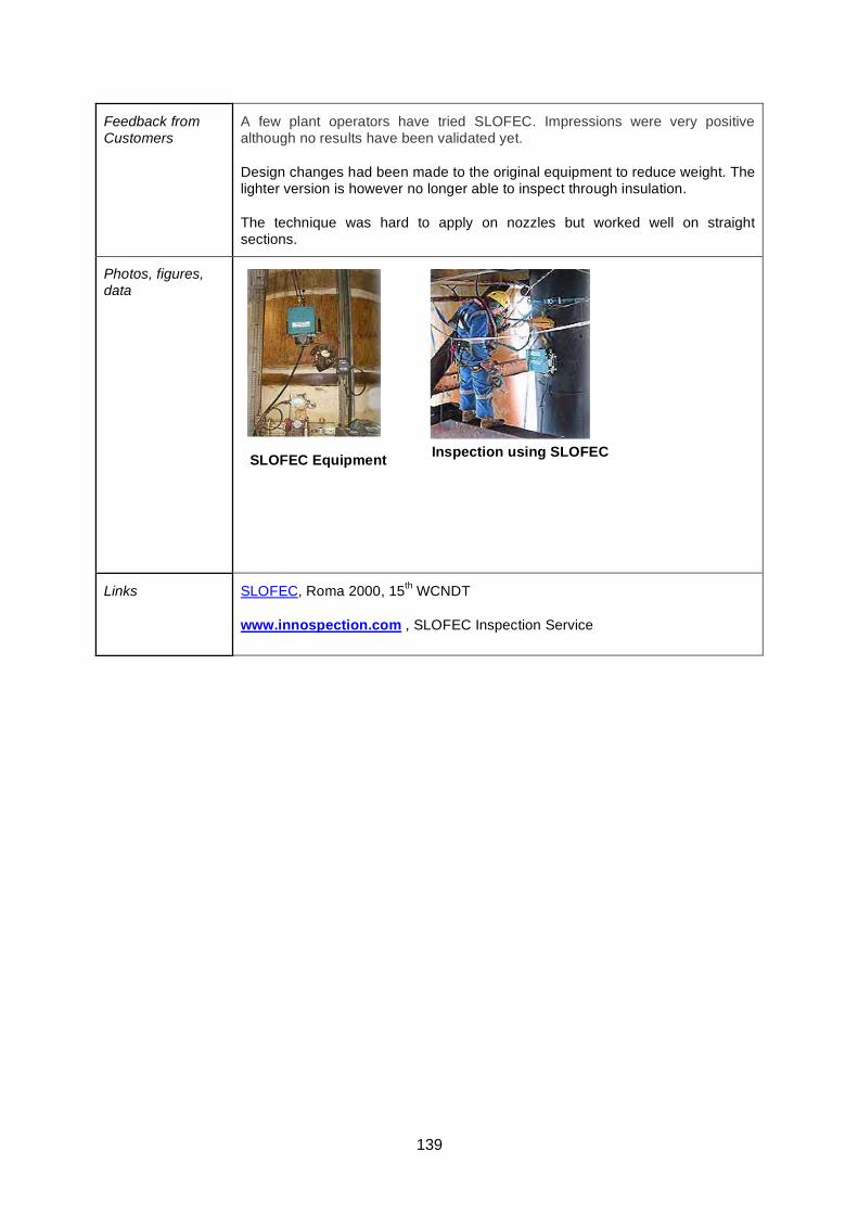
139
Feedback from Customers
A few plant operators have tried SLOFEC. Impressions were very positive although no results have been validated yet.
Design changes had been made to the original equipment to reduce weight. The lighter version is however no longer able to inspect through insulation.
The technique was hard to apply on nozzles but worked well on straight sections.
Photos, figures, data
Links SLOFEC, Roma 2000, 15th WCNDT
www.innospection.com , SLOFEC Inspection Service
Inspection using SLOFEC SLOFEC Equipment
140
Pulsed Eddy Current (PEC) Technique Datasheet
Basis of Technique
This sheet describes the Pulsed Eddy Current technology as developed and licensed by Shell Global Solutions.
A current pulse is sent through a coil. When the current is interrupted eddy currents are generated in the material, which will decay in time. Measuring the rate of decay of the eddy currents will determine the wall thickness. High wall thickness will result in a slower decay.
General inspection capabilities
• Carbon steel or low alloy ferromagnetic metals
• Wall Thickness between 2-35 mm
• Insulation thickness up to 200 mm
• Can detect erosion corrosion, flow accelerated corrosion and corrosion under insulation
• On stream
• Can measure through any kind of non magnetic insulation (e.g. rockwool, foamglas, concrete, marine growth, dirt, cladding and scaling)
• Can be applied in wet or underwater conditions
• Measures through aluminium, stainless steel or galvanised (up to 1 mm) sheeting
• No surface preparation necessary
• The accuracy is roughly 5% of the reference (100%).
• Repeatability on the same spot can be as good as 0.2% in corrosion monitoring applications.
• A rough rule of thumb is smallest detectable defect diameter is 50% of the lift-off, i.e. in 50mm of insulation the smallest detectable defect diameter is around 25mm.
• PEC is a screening tool for inspecting remaining wall thickness under coatings and insulations. Not considered rapid.
Operating Temperature
Temperature range -150 to 500 degrees Celsius
Operator Dependency
Trained and skilled operators are required.
Inspection limitations
• The PEC wall thickness is an average over its ‘footprint’, i.e. the area where eddy currents flow. The size of the footprint area depends on the distance between probe and metal surface. The footprint is approximately a circle with a diameter depending on the distance between probe and steel surface. The PEC wall thickness readings are an average value over this footprint area. As a result, PEC can only detect general wall loss. Localised corrosion such as pitting is not detected by PEC
• In principle no differentiation between internal and external defects.
• PEC readings depend not only on the thickness of the steel, but also on the
141
electromagnetic properties of the steel, in particular the electrical conductivity and magnetic permeability. These properties depend on steel grade and often vary from one batch of steel to the next. For absolute wall thickness measurements, the PEC instrument must therefore be calibrated on the same object that is inspected, or on the same batch of the steel as the test specimen.
Access requirements
• Rope access is possible
• A clearance of 1,5 x the insulation thickness if to measure between two pipes (e.g. in a pipe bridge).
Parameters affecting inspections capabilities
• Pulsed Eddy Current is aimed at the detection of larger area (not localised) corrosion.
• Data analysis displays average thickness over probe-footprint and will therefore not detect isolated or small clusters of pits. In areas with pitting corrosion the minimum thickness will therefore be lower than the data output thickness.
• PEC wall thickness readings are relative values, showing variations in wall thickness on the object being inspected. Absolute readings can be obtained by a wall thickness calibration at one point of the object.
Operator training and certification requirements
Shell Global Solutions provide level 1 and level 2 PEC training and certification. Operators that perform PEC measurements must be level 1 certified. Staff that analyse and report PEC data must be level 2 certified.
Inspection personnel taking a level 1 PEC course should be minimum qualified to level 2 UT or equivalent.
Qualifications/trials results/field evidence
Some successful PEC applications where the non-contact, high repeatability, play role at its strengths are:
• Support leg inspection where a thickness profile is obtained by measuring through the fire proofing (typically concrete).
• Offshore riser, caisson or well casing inspection. In these applications a typical degradation mechanism is general thinning in the splash zone. It can be applied from the topside or ROV.
• In-service corrosion/erosion monitoring. In dedicated corrosion monitoring applications repeatability of 0.2% can be achieved which enables early detection of a change in corrosion rate.
• In-service storage tank inspection where a flat PEC probe is inserted in the gap between annular ring and tank base.
Commercial availability (product)
Shell Global Solutions has developed over the past few years Pulsed Eddy Current (PEC) technology. The technique can be licensed to the asset owner for inspection of its equipment.
Commercial availability (service)
Shell Global Solutions can provide specialised PEC inspections services but the technology is also licensed to a number of inspection service companies.
Shell Global Solutions International B.V. P.O. Box 38000 1030 BN Amsterdam The Netherlands Website : http://www.shell.com/home/content/globalsolutions-en
• As of May 2008, the following inspection service companies have a PEC
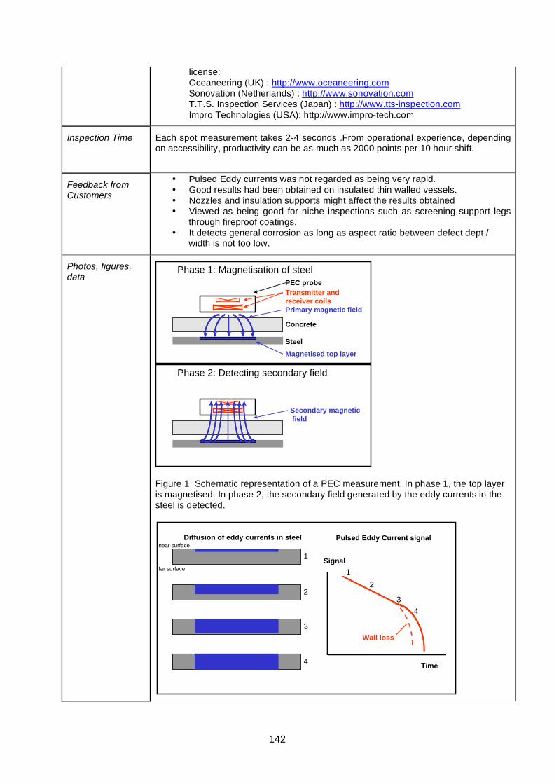
142
license: Oceaneering (UK) : http://www.oceaneering.com Sonovation (Netherlands) : http://www.sonovation.com T.T.S. Inspection Services (Japan) : http://www.tts-inspection.com Impro Technologies (USA): http://www.impro-tech.com
Inspection Time Each spot measurement takes 2-4 seconds .From operational experience, depending on accessibility, productivity can be as much as 2000 points per 10 hour shift.
Feedback from Customers
• Pulsed Eddy currents was not regarded as being very rapid. • Good results had been obtained on insulated thin walled vessels. • Nozzles and insulation supports might affect the results obtained • Viewed as being good for niche inspections such as screening support legs
through fireproof coatings. • It detects general corrosion as long as aspect ratio between defect dept /
width is not too low.
Photos, figures, data
PEC probeTransmitter and receiver coilsPrimary magnetic field
Concrete
SteelMagnetised top layer
Phase 1: Magnetisation of steel
Phase 2: Detecting secondary field
Secondary magnetic field
Figure 1 Schematic representation of a PEC measurement. In phase 1, the top layer is magnetised. In phase 2, the secondary field generated by the eddy currents in the steel is detected.
1
2
3
4
Diffusion of eddy currents in steel
Signal
Time
12
34
Wall loss
Pulsed Eddy Current signalnear surface
far surface
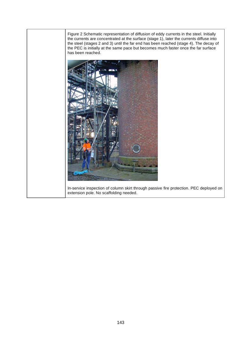
143
Figure 2 Schematic representation of diffusion of eddy currents in the steel. Initially the currents are concentrated at the surface (stage 1), later the currents diffuse into the steel (stages 2 and 3) until the far end has been reached (stage 4). The decay of the PEC is initially at the same pace but becomes much faster once the far surface has been reached.
In-service inspection of column skirt through passive fire protection. PEC deployed on extension pole. No scaffolding needed.
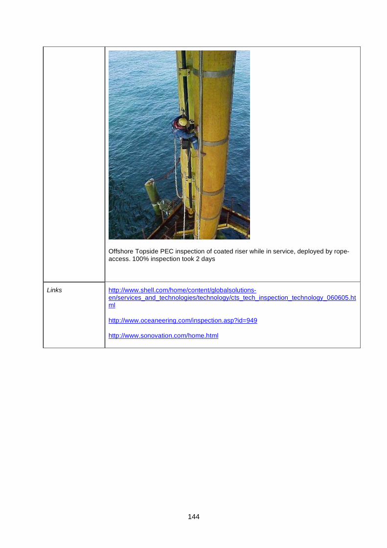
144
Offshore Topside PEC inspection of coated riser while in service, deployed by rope-access. 100% inspection took 2 days
Links http://www.shell.com/home/content/globalsolutions-en/services_and_technologies/technology/cts_tech_inspection_technology_060605.html
http://www.oceaneering.com/inspection.asp?id=949
http://www.sonovation.com/home.html
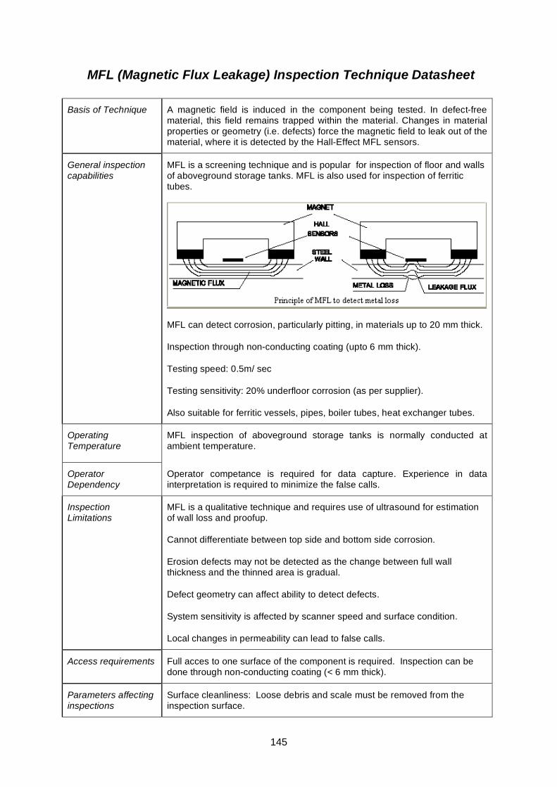
145
MFL (Magnetic Flux Leakage) Inspection Technique Datasheet
Basis of Technique A magnetic field is induced in the component being tested. In defect-free material, this field remains trapped within the material. Changes in material properties or geometry (i.e. defects) force the magnetic field to leak out of the material, where it is detected by the Hall-Effect MFL sensors.
General inspection capabilities
MFL is a screening technique and is popular for inspection of floor and walls of aboveground storage tanks. MFL is also used for inspection of ferritic tubes.
MFL can detect corrosion, particularly pitting, in materials up to 20 mm thick.
Inspection through non-conducting coating (upto 6 mm thick).
Testing speed: 0.5m/ sec
Testing sensitivity: 20% underfloor corrosion (as per supplier).
Also suitable for ferritic vessels, pipes, boiler tubes, heat exchanger tubes.
Operating Temperature
MFL inspection of aboveground storage tanks is normally conducted at ambient temperature.
Operator Dependency
Operator competance is required for data capture. Experience in data interpretation is required to minimize the false calls.
Inspection Limitations
MFL is a qualitative technique and requires use of ultrasound for estimation of wall loss and proofup.
Cannot differentiate between top side and bottom side corrosion.
Erosion defects may not be detected as the change between full wall thickness and the thinned area is gradual.
Defect geometry can affect ability to detect defects.
System sensitivity is affected by scanner speed and surface condition.
Local changes in permeability can lead to false calls.
Access requirements Full acces to one surface of the component is required. Inspection can be done through non-conducting coating (< 6 mm thick).
Parameters affecting inspections
Surface cleanliness: Loose debris and scale must be removed from the inspection surface.
146
capabilities Surface Irregularities: Irregularies in tankfloor surface affect the defect detection capability of MFL
Operator training and certification requirements
Silverwing (UK) Ltd and MFE Enterprise Inc. offer equipment specific training and certification.
Qualifications/trials results/field evidence
RACH trials [1] provide: probability of detection (PoD) tables; reliability operating characteristics (ROC) plots, which are PoD vs PFI (probability of false indication); and plots of measured vs. actual defect size and/or depth.
CRIS trials [2] extended the RACH trials.
Commercial availability (product)
MFL products for aboveground storage tank inspection are available from following suppliers:
MFE Enterprises Inc Silverwing (UK) Ltd 14101 Hwy 290 West Building 700 Austin, Texas 78737 U.S.A. Phone: 1 281 441 8284 Fax: 1 281 441 8361 Email:[email protected] Website: http://www.mfescan.com
Unit 31 Cwmdu Industrial Estate Carmarthen Road Swansea SA5 8JF, Wales UK. Phone: 01792585533 Fax: 01792 586044 Email: [email protected] Website: www.silverwinguk.com
Commercial availability (service)
Contact Silverwing (UK) Ltd and MFE Inc. for further information on service providers.
Inspection Time Pipes: forward speed of 450 mm/sec, scanning width depends on scanning head used.
Floor scanners: up to 7 m2 per minute
Feedback from Customers
MFL is the widely used technique for inspection of ferritic materials. Customer experience to MFL is mixed. False call rates and missed defects can be particularly high in certain conditions. SLOFEC has certain advantages over MFL regardi
ng depth of penetration and defect detection.
Photos, figures, data Probability of detection (PoD) values for bare pipe in the RACH trials [1, p. 15]:
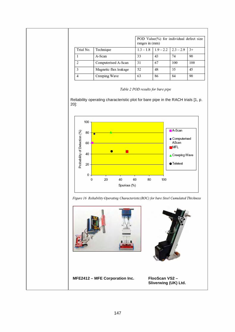
147
Reliability operating characteristic plot for bare pipe in the RACH trials [1, p. 20]:
MFE2412 – MFE Corporation Inc. FlooScan VS2 – Sliverwing (UK) Ltd.
148
Links RACH report [1] on HSE website (PDF, 494 KB).
MFL for tank floor scanning
MFE 2412 Brochure MFE Corporation Inc.
Floormap VS2 Silverwing (UK) Ltd
References [1] Reliability assessment for containers of hazardous material RACH, Technical Software Consultants Limited for the HSE, Offshore Technology Report 2000/095, 2001.
[2] Corrosion Reliability Inspection Scheduling (access restricted to HOIS2000 members)
[3] Document for magnetic flux leakage inspection of atmospheric storage tank floor– HSE Research Report No. 481, 2006

149
MFL Pipescan Technique Datasheet
Basis of Technique
Pipescan:
One of a range of fixed or adjustable MFL scaning heads to suit a variety of pipe diameters is moved across the external surface of the pipe and will detect internal and external corrosion pitting. The system includes a separate electronics module with an operator adjustable alarm threshold control. The defect alarm consists of an audible alarm and L.E.D.s.
General inspection capabilities
Used as a screening tool, Pipescan is capable of detecting corrosion pitting originating from the internal and/or external surface of the pipe. The system has no sizing capabilities.
Operating Temperature
Pipe surface temperature range must be between -20OC and 100OC.
Operator Dependency
System sensitivity is affected by scanner speed. Operator must maintain a fairly uniform scanner speed.
Inspection limitations
The longitudinal scanning heads cannot inspect a limited area each side of a circumferential weld or flange. Circumferential scanning heads are available to inspect these areas.
A limited area adjacent to longitudinal welds is not covered by Pipescan inspections.
Pipescan scanning heads cannot pass bends / elbows and severely distorted areas of pipe.
Wall thickness up to 19 mm; coatings up to 6 mm.
Minimum clearance around pipes: 120 mm.
Access requirements
Full acces to the external surface of the pipe is required.
Parameters affecting inspections capabilities
Varying paint thicknesses (particularly at the underside of the pipe), severe external corrosion and out of roundness can cause false indications or cause scanning head obstructions.
The scanner is able to move in a straight line only, elbows and bends cannot be inspected.
Erosion defects may not be detected as the change between full wall thickness and the thinned area is gradual.
Defect geometry can affect ability to detect defects.
System sensitivity is affected by scanner speed. Operator must maintain a scanner speed of between 300mm and 500mm per second.
The Pipescan is a screening tool only. A secondary inspection is required to quantify loss.
The Pipescan can be used on pipe wall thicknesses of between 6mm and

150
19mm. Max sensitivity depends on wall thickness.
Operator training and certification requirements
Contact Silverwing (UK) Ltd for training requirements.
Qualifications/trials results/field evidence
RACH trials [1] provide: probability of detection (PoD) tables; reliability operating characteristics (ROC) plots, which are PoD vs PFI (probability of false indication); and plots of measured vs. actual defect size and/or depth.
CRIS trials [2] extended the RACH trials.
Commercial availability (product)
Available from Silverwing.
Silverwing (UK) Ltd Unit 31 Cwmdu Industrial Estate Carmarthen Road Swansea SA5 8JF, Wales UK. Tel: +44 (0) 1792 585533 Fax: +44 (0) 1792 586044 Email: [email protected]
Website: http://www.silverwinguk.com
Commercial availability (service)
Due to the ease of use and low initial capital cost of the system, any NDT service company can purchase the system and offer service.
Silverwing also provide inspection service. http://www.silverwingme.com
Inspection Time Forward speed of 450mm per second.
Scanning width depends on scanning head used.
Feedback from Customers
Feedback from several companies using the system in Countries with relatively low labour costs suggest they consider the Pipescan system to be the most cost effective commercially available system for inspecting above gound pipelines.
Photos, figures, data
Inspection using Pipescan
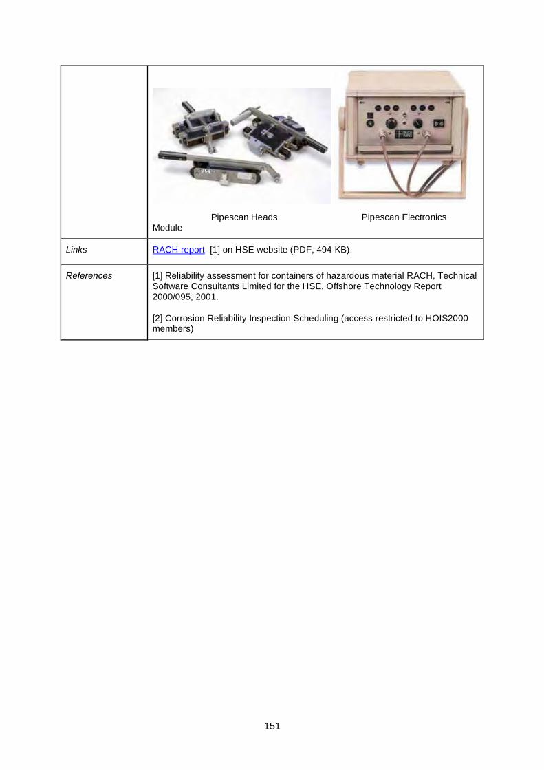
151
Pipescan Heads Pipescan Electronics Module
Links RACH report [1] on HSE website (PDF, 494 KB).
References [1] Reliability assessment for containers of hazardous material RACH, Technical Software Consultants Limited for the HSE, Offshore Technology Report 2000/095, 2001.
[2] Corrosion Reliability Inspection Scheduling (access restricted to HOIS2000 members)
152
Microwave Technique - Datasheet
Basis of Technique Microwave signals readily penetrate inside non-conducting materials and may therefore be employed for defect detection within these materials, but have no penetrating ability for conducting materials such as metals. Microwaves normally measure the dielectric properties of a non-conducting material.
Microwaves are radiated from the transducer to the specimen being tested. A detectable signal is returned at each interface where the dielectric constant changes (e.g. - where there are delaminations, cracks, holes, impurities or other defects). The transducer may be moved relative to the specimen at any desired speed and the scanning speed need not be uniform.
Once the data is collected, the software allows the image to be manipulated to enhance features. Also, since it is in digital form, the scan results can be stored and retrieved later to provide information on how a part or a defect has changed over time. This allows determination of the growth rate of a defect, which is critical to determining ultimate service life.
General inspection capabilities
Detection of defects such as delaminations, disbands and impact damage in dielectric materials such as fibre reinforced polymeric (FRP) materials.
Can operate in contact or non-contact mode, and from one side only or from both sides (reflection or through-transmission).
Full volumetric coverage can be obtained.
Operating Temperature
Not specified, but since it can operate in a non-contact mode, then it should have a very wide operating temperature window.
Operator Dependency
High; specialist method.
Inspection limitations
• Does not inspect sub surface defects in metal
• The microwaves do not penetrate fully through all pipe-repairs. Reasons for this might be further understood through trials but could be due to conductivity of carbon fibre in CFRP.
• Applicable to non-conductive materials only
• Moisture or liquid may affect results.
Access requirements
Access required to manually attach scanner and probes.
Parameters affecting inspection capabilities
Predominant factor is conductivity of test object; any conductivity stops transmission of microwaves.
Operator training and certification requirements
Specialist method supplied by expert service providers. No formal certification available.
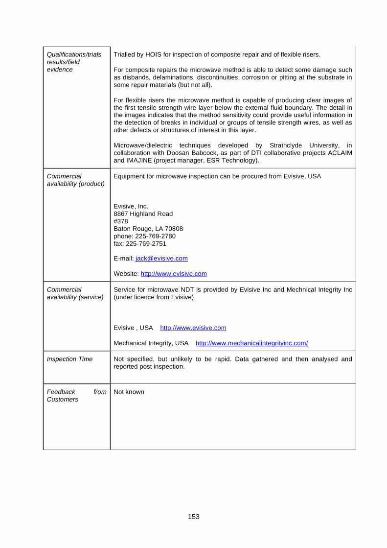
153
Qualifications/trials results/field evidence
Trialled by HOIS for inspection of composite repair and of flexible risers.
For composite repairs the microwave method is able to detect some damage such as disbands, delaminations, discontinuities, corrosion or pitting at the substrate in some repair materials (but not all).
For flexible risers the microwave method is capable of producing clear images of the first tensile strength wire layer below the external fluid boundary. The detail in the images indicates that the method sensitivity could provide useful information in the detection of breaks in individual or groups of tensile strength wires, as well as other defects or structures of interest in this layer.
Microwave/dielectric techniques developed by Strathclyde University, in collaboration with Doosan Babcock, as part of DTI collaborative projects ACLAIM and IMAJINE (project manager, ESR Technology).
Commercial availability (product)
Equipment for microwave inspection can be procured from Evisive, USA
Evisive, Inc. 8867 Highland Road #378 Baton Rouge, LA 70808 phone: 225-769-2780 fax: 225-769-2751
E-mail: [email protected]
Website: http://www.evisive.com
Commercial availability (service)
Service for microwave NDT is provided by Evisive Inc and Mechnical Integrity Inc (under licence from Evisive).
Evisive , USA http://www.evisive.com
Mechanical Integrity, USA http://www.mechanicalintegrityinc.com/
Inspection Time Not specified, but unlikely to be rapid. Data gathered and then analysed and reported post inspection.
Feedback from Customers
Not known
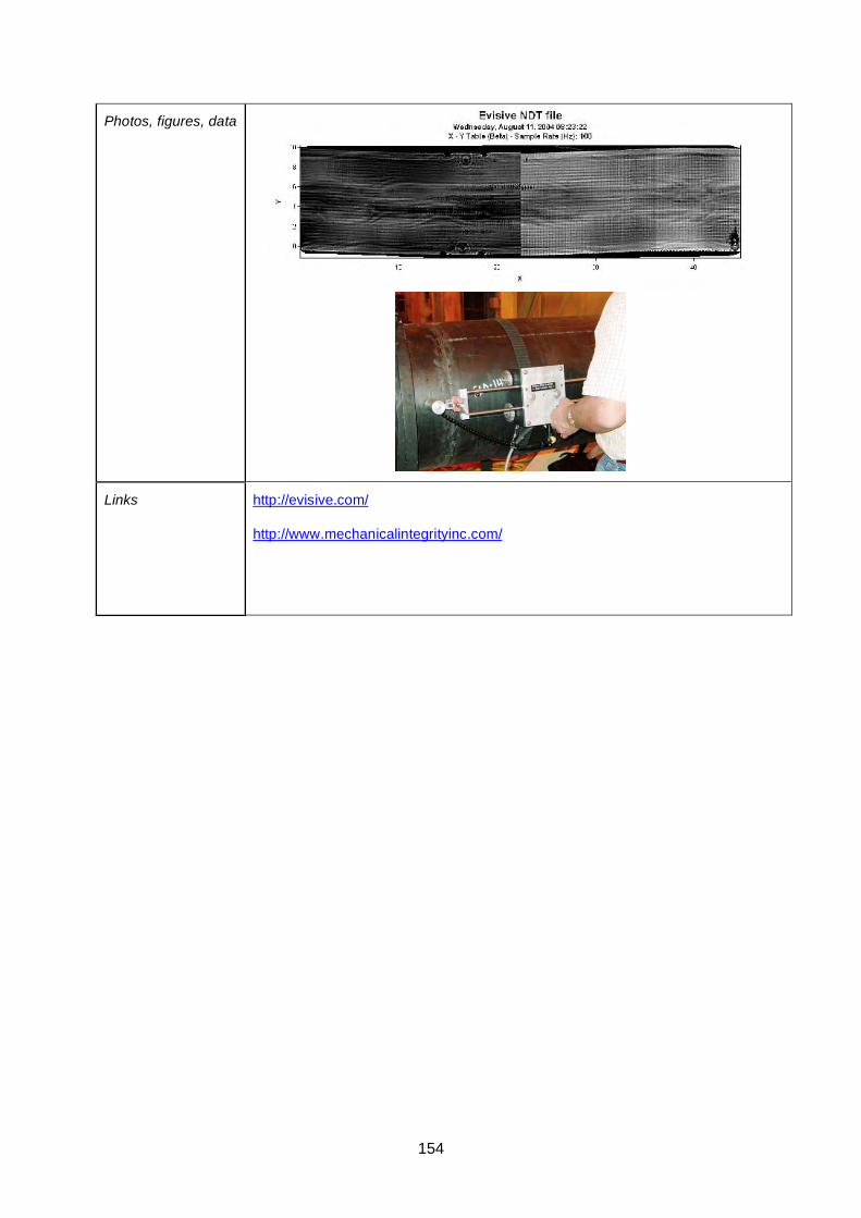
154
Photos, figures, data
Links http://evisive.com/
http://www.mechanicalintegrityinc.com/
155
Thermography Technique Datasheet
Basis of Technique
Thermography measures surface temperature. It can amongst others be used to measures water presence in insulation or damage of insulation through variations in surface temperature or to detect sand levels and build ups in pipe and vessels. Other applications include integrity of electrical components and as an aid in vibration analysis.
Thermography is a remote condition monitoring technique which identifies the surface temperatures by the measurement of the intensity of infra-red radiation emitted from a surface. Infrared energy is generated by the vibration and rotation of atoms and molecules. The higher the temperature of an object, the higher the emitted infrared energy due to more motion in the atoms and molecules. This is the energy detected by infrared cameras.
The cameras do not see temperatures but detect the thermal radiation emitted from the component.
The presence of water will be measured in terms of temperature variations (e.g. variations of emitted infra red radiation) of the insulation weather proofing along the pipe, arising from a loss in thermal efficiency of the insulation system.
General inspection capabilities
Resolution up to 0.1°C can be detected depending on camera and extra options utilised.
Thermal camera pixels (governs the smallest detectable "hot spot") ranging from: 320 x 240 for the expensive cameras to 16 x 16 for the budget options.
If a standard 20 degree IRISYS imager is used to look at scene 5 metres away, it will accurately be able to measure ‘hot spots’, which are larger than 11cm that cover a pixel.
A low resolution Flir camera will measure hotspots from 10mm at 5 metres (and hotspots from the size of 6mm for the higher resolution option).
Cameras with 0.02°C thermal sensitivity are used for dynamic images.
Operating Temperature
Temperature ranges that can be measured: -40°C up to +2000°C
Operator Dependency
Yes.
Inspection limitations
* Results can be distorted if hot pipes and shiny cladding are present close to inspection area - something that is likely to happen in reality. Preferable to carry out inspection after heavy rain to obtain "worst condition" data. A large enough temperature gradient required at the surface where the insulation is damaged for detection.
* For CUI inspections a 30°C temperature gradient across the insulation (between pipe and environment) is desired to ensure detection.
* The method is only detecting presence of water. On hot components the insulation might be drying rapidly and therefore only be wet for a very limited time. The defective/moist zone might then not be visible to the infrared camera.
156
Access requirements
Distance does not effect the measurement. However, infrared instruments measure the energy from a circular spot on the target, the farther away from the target the sensor is, the larger the spot. Consequently, distance is limited by the size of the object and the distance to the object you want to measure. Flir recommendations 10-12 meters. The camera could be mounted on carrier if needed.
Parameters affecting inspections capabilities
* Resolution of camera - number of pixels and Field of View (FOV). Some thermal imagers utilise a fixed focus lens, therefore the imager’s field of view (FOV) increases as the distance from the scene increases. For the imager to make an accurate temperature measurement, the ‘hot spot’ being displayed must cover at least one whole pixel. The pixel size is directly related to the FOV size. * Temperature range: Detectable Temperatures * Maximum working distance * Solar reflection and solar gain on targets and surrounding components can affect the result
Operator training and certification requirements
ASNT and EPRI qualified training courses available up to Level III
Qualifications/trials results/field evidence
* Good correlation in field with detecting levels of build up in separators and risers.
* Data information regarding moist insulation is not conclusive due to the many factors that can affect the results.
Commercial availability (product)
There are several thermal camera systems available with “Flir System” being regarded as the world leader.
Flir Thermography 2 Kings Hill Avenue Kings Hill, West Malling, Kent ME19 4AQ, United Kingdom
Tel: +44 1732 221 245
Fax: +44 1732 843707
E-mail: [email protected]
Website: http://www.flirthermography.co.uk
Commercial availability (service)
CET Medway Limited : http://www.cetmedway.co.uk/
IRISYS : http://www.irisys.co.uk/
Ti Thermal Imaging Ltd : http://www.thermalimaging.co.uk/
Contact TWI for expert consultancy. www.twi.co.uk
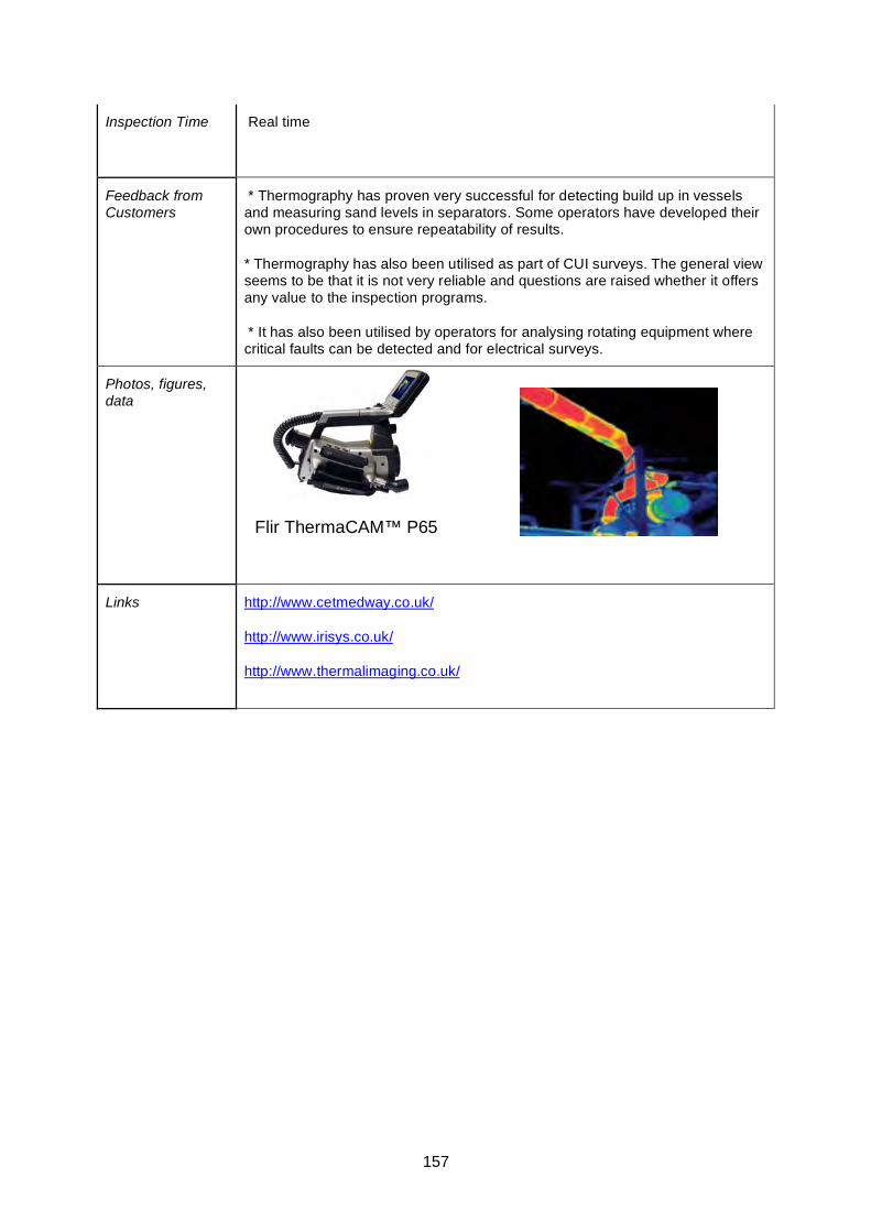
157
Inspection Time Real time
Feedback from Customers
* Thermography has proven very successful for detecting build up in vessels and measuring sand levels in separators. Some operators have developed their own procedures to ensure repeatability of results.
* Thermography has also been utilised as part of CUI surveys. The general view seems to be that it is not very reliable and questions are raised whether it offers any value to the inspection programs.
* It has also been utilised by operators for analysing rotating equipment where critical faults can be detected and for electrical surveys.
Photos, figures, data
Links http://www.cetmedway.co.uk/
http://www.irisys.co.uk/
http://www.thermalimaging.co.uk/
Flir ThermaCAM™ P65
158
Shearography Technique Datasheet
Basis of Technique
An optical method to detect surface strain variation induced by the presence of sub-surface defects.
General inspection capabilities
Shearography is a non-contact method for fast, large-area defect detection and structural analysis.
• Holographic and Speckle interferometry can produce surface maps of relative displacement
• Speckle techniques detect surface strain variation induced by the presence of the subsurface defect
The instrument can identify composite structural defects such as delaminations, disbonds, impact damage, voids, inclusions and cracks. Detection is possible to depths up to 100mm in the material depending on structural rigidity and loading mechanisms.
Using the results gained from the instrument, engineers and designers can assess how an object is responding to an induced force. From this assessment they can then determine whether the component design needs changing or whether there are problems in the item as manufactured.
Basic Principle of Sheorography
Laser beams are monochromatic (single wavelength), highly directional and are spatially and temporally coherent. This coherent property of a laser beam, where all emitted waves are in phase with each other, enables its use for strain measurement. The beam incident on the target is reflected by its surface. Most surfaces are not optically flat. The surface roughness causes the reflected waves of light to interfere with each other creating a grainy effect that is known as speckle.
The detection system comprises of an image shearing head, a phase stepper, an imaging lens and a camera. The strain field is produced by saving an image of the unstressed target, and subtracting all subsequent images from this reference image. As a mechanical or thermal stress is applied to the target surface, the phase of the speckle changes corresponding to the stress. This is visible as fringes in the subtracted video.
Indications about defect location and appearance can be found by studying the resulting fringes.
Rigid movement produces displacement but no strain thus the technique is insensitive to environmental disturbances and is well suited for industrial applications.
Able to detect defects at depth within a variety of materials including composites, honeycomb structures and thin plate.
Extensively used in aerospace / automotive industry. Other applications include: Commercial applications that successfully utilise this technology include: • Marine – currently used for new build, bi-annual and accident
159
investigations by the RNLI • Construction – validate design parameters and assess reinforcement bonding integrity • Transport – within the rail industry to inspect bonding integrity and environmental effects • Aerospace – determination of bonding strength in composite structures. • Medical - prosthetic implant design evaluation and surgery investigations. • Power Generation – gas turbine and wind turbine blade inspection
System effective at
• Manufacture – defect free • Repairs - verification • In the field – transport/assembly damage • Annual audits – defect propagation/RLP • in situ testing
Operating Temperature
5 ºC – 35 ºC
Operator Dependency
Yes.
Inspection limitations
Vibration of surrounding structure? Can be viable if the system is mounted rigid to the structure under test such that both instrument and structure are vibrating in phase.
50mm deep defect canbe detected. Larger defects may be detected deeper into the structure.
Access requirements
Access to restricted areas can be achieved using mirrors.
Parameters affecting inspections capabilities
Successful application of the technique depends on depth and type of defect, type of material, shearing amount and direction, the manner of load and laser illumination.
Operator training and certification requirements
This is a specialist technique.
Qualifications/trials results/field evidence
Limited trials administered by Doosan Babcock covering corrosion in pipe underneath composite wrap. Results indicated promise.
Commercial availability (product)
Laser Strain Mapper from Laser Optical Engineering.
Laser Optical Engineering Ltd, PO Box 6321 Loughborough Leicestershire LE11 3XZ
T. +44(0)1509 228733 F. +44(0)1509 223948
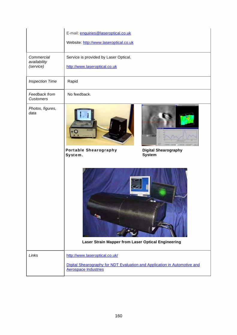
160
E-mail: [email protected]
Website: http://www.laseroptical.co.uk
Commercial availability (service)
Service is provided by Laser Optical.
http://www.laseroptical.co.uk
Inspection Time Rapid
Feedback from Customers
No feedback.
Photos, figures, data
Links http://www.laseroptical.co.uk/
Digital Shearography for NDT Evaluation and Application in Automotive and Aerospace Industries
Portable Shearography System.
Digital Shearography System
Laser Strain Mapper from Laser Optical Engineering

161
APPENDIX 6
STATISTICAL METHODS

162
163
Example Statistical Methods for Sample Inspections
Two examples of statistical methods which can be useful tools for non-invasive inspection
are provided.
The first method is extreme value statistical analysis. This can be useful for predicting what
the maximum corrosion pit depth in a vessel zone is, based on a sample inspection for
pitting within that zone. It can also be used to help determine what the sample size should
be in order to achieve a particular level of confidence in the conclusions.
The second example covers the use of statistical methods to determine what the probability
of detecting at least one defect (and therefore revealing that a particular degradation
mechanism is active) as a function of sample size and how widespread the degradation is.
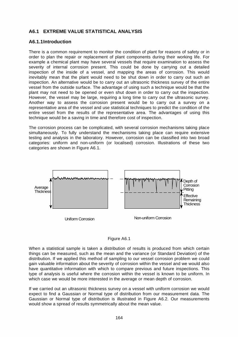
164
A6.1 EXTREME VALUE STATISTICAL ANALYSIS
A6.1.1 Introduction
There is a common requirement to monitor the condition of plant for reasons of safety or in order to plan the repair or replacement of plant components during their working life. For example a chemical plant may have several vessels that require examination to assess the severity of internal corrosion present. This could be done by carrying out a detailed inspection of the inside of a vessel, and mapping the areas of corrosion. This would inevitably mean that the plant would need to be shut down in order to carry out such an inspection. An alternative would be to carry out an ultrasonic thickness survey of the entire vessel from the outside surface. The advantage of using such a technique would be that the plant may not need to be opened or even shut down in order to carry out the inspection. However, the vessel may be large, requiring a long time to carry out the ultrasonic survey. Another way to assess the corrosion present would be to carry out a survey on a representative area of the vessel and use statistical techniques to predict the condition of the entire vessel from the results of the representative area. The advantages of using this technique would be a saving in time and therefore cost of inspection.
The corrosion process can be complicated, with several corrosion mechanisms taking place simultaneously. To fully understand the mechanisms taking place can require extensive testing and analysis in the laboratory. However, corrosion can be classified into two broad categories: uniform and non-uniform (or localised) corrosion. Illustrations of these two categories are shown in Figure A6.1.
Uniform Corrosion Non-uniform Corrosion
Depth ofCorrosionPittingEffectiveRemainingThickness
AverageThickness
Figure A6.1
When a statistical sample is taken a distribution of results is produced from which certain things can be measured, such as the mean and the variance (or Standard Deviation) of the distribution. If we applied this method of sampling to our vessel corrosion problem we could gain valuable information about the severity of corrosion within the vessel and we would also have quantitative information with which to compare previous and future inspections. This type of analysis is useful where the corrosion within the vessel is known to be uniform. In which case we would be more interested in the average or mean depth of corrosion.
If we carried out an ultrasonic thickness survey on a vessel with uniform corrosion we would expect to find a Gaussian or Normal type of distribution from our measurement data. The Gaussian or Normal type of distribution is illustrated in Figure A6.2. Our measurements would show a spread of results symmetrically about the mean value.
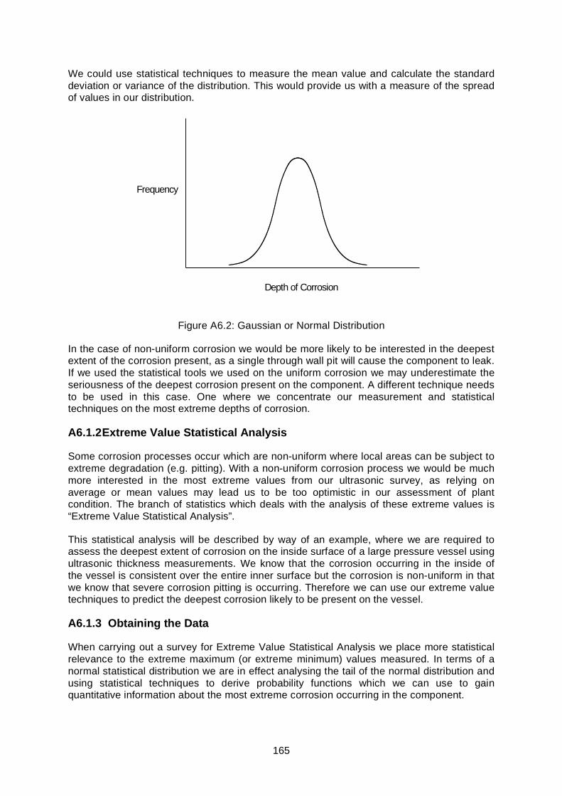
165
We could use statistical techniques to measure the mean value and calculate the standard deviation or variance of the distribution. This would provide us with a measure of the spread of values in our distribution.
Depth of Corrosion
Frequency
Figure A6.2: Gaussian or Normal Distribution
In the case of non-uniform corrosion we would be more likely to be interested in the deepest extent of the corrosion present, as a single through wall pit will cause the component to leak. If we used the statistical tools we used on the uniform corrosion we may underestimate the seriousness of the deepest corrosion present on the component. A different technique needs to be used in this case. One where we concentrate our measurement and statistical techniques on the most extreme depths of corrosion.
A6.1.2 Extreme Value Statistical Analysis
Some corrosion processes occur which are non-uniform where local areas can be subject to extreme degradation (e.g. pitting). With a non-uniform corrosion process we would be much more interested in the most extreme values from our ultrasonic survey, as relying on average or mean values may lead us to be too optimistic in our assessment of plant condition. The branch of statistics which deals with the analysis of these extreme values is “Extreme Value Statistical Analysis”.
This statistical analysis will be described by way of an example, where we are required to assess the deepest extent of corrosion on the inside surface of a large pressure vessel using ultrasonic thickness measurements. We know that the corrosion occurring in the inside of the vessel is consistent over the entire inner surface but the corrosion is non-uniform in that we know that severe corrosion pitting is occurring. Therefore we can use our extreme value techniques to predict the deepest corrosion likely to be present on the vessel.
A6.1.3 Obtaining the Data
When carrying out a survey for Extreme Value Statistical Analysis we place more statistical relevance to the extreme maximum (or extreme minimum) values measured. In terms of a normal statistical distribution we are in effect analysing the tail of the normal distribution and using statistical techniques to derive probability functions which we can use to gain quantitative information about the most extreme corrosion occurring in the component.
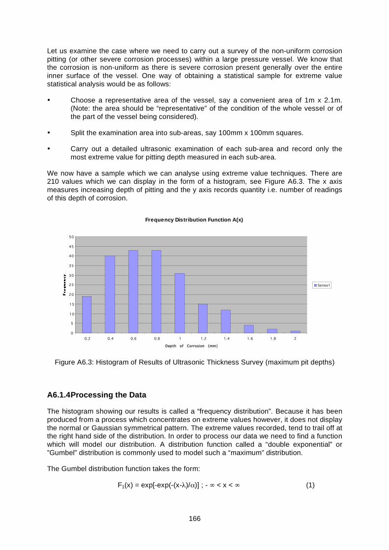
166
Let us examine the case where we need to carry out a survey of the non-uniform corrosion pitting (or other severe corrosion processes) within a large pressure vessel. We know that the corrosion is non-uniform as there is severe corrosion present generally over the entire inner surface of the vessel. One way of obtaining a statistical sample for extreme value statistical analysis would be as follows:
• Choose a representative area of the vessel, say a convenient area of 1m x 2.1m. (Note: the area should be “representative” of the condition of the whole vessel or of the part of the vessel being considered).
• Split the examination area into sub-areas, say 100mm x 100mm squares.
• Carry out a detailed ultrasonic examination of each sub-area and record only the most extreme value for pitting depth measured in each sub-area.
We now have a sample which we can analyse using extreme value techniques. There are 210 values which we can display in the form of a histogram, see Figure A6.3. The x axis measures increasing depth of pitting and the y axis records quantity i.e. number of readings of this depth of corrosion.
Frequency Distribution Function A(x)
0
5
10
15
20
25
30
35
40
45
50
0.2 0.4 0.6 0.8 1 1.2 1.4 1.6 1.8 2
Depth of Corrosion (mm)
Series1
Figure A6.3: Histogram of Results of Ultrasonic Thickness Survey (maximum pit depths)
A6.1.4 Processing the Data
The histogram showing our results is called a “frequency distribution”. Because it has been produced from a process which concentrates on extreme values however, it does not display the normal or Gaussian symmetrical pattern. The extreme values recorded, tend to trail off at the right hand side of the distribution. In order to process our data we need to find a function which will model our distribution. A distribution function called a “double exponential” or ”Gumbel” distribution is commonly used to model such a “maximum” distribution.
The Gumbel distribution function takes the form:
F1(x) = exp[-exp(-(x-λ)/α)] ; - ∞ < x < ∞ (1)
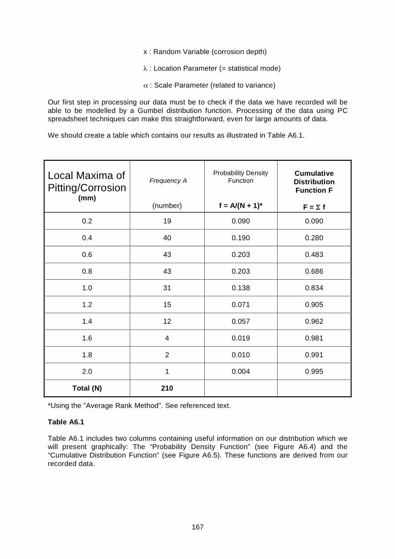
167
x : Random Variable (corrosion depth)
λ : Location Parameter (= statistical mode)
α : Scale Parameter (related to variance)
Our first step in processing our data must be to check if the data we have recorded will be able to be modelled by a Gumbel distribution function. Processing of the data using PC spreadsheet techniques can make this straightforward, even for large amounts of data.
We should create a table which contains our results as illustrated in Table A6.1.
Local Maxima of Pitting/Corrosion
(mm)
Frequency A
(number)
Probability Density
Function
f = A/(N + 1)*
Cumulative Distribution Function F
F = Σ f
0.2 19 0.090 0.090
0.4 40 0.190 0.280
0.6 43 0.203 0.483
0.8 43 0.203 0.686
1.0 31 0.138 0.834
1.2 15 0.071 0.905
1.4 12 0.057 0.962
1.6 4 0.019 0.981
1.8 2 0.010 0.991
2.0 1 0.004 0.995
Total (N) 210
*Using the ”Average Rank Method”. See referenced text.
Table A6.1
Table A6.1 includes two columns containing useful information on our distribution which we will present graphically: The “Probability Density Function” (see Figure A6.4) and the “Cumulative Distribution Function” (see Figure A6.5). These functions are derived from our recorded data.
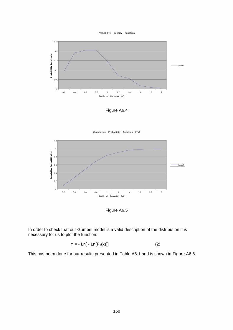
168
Probabil ity Density Function
0
0.05
0.1
0.15
0.2
0.25
0.2 0.4 0.6 0.8 1 1.2 1.4 1.6 1.8 2
Depth of Corrosion (x) mm
Series1
Figure A6.4
Cumulative Probability Function F(x)
0
0.2
0.4
0.6
0.8
1
1.2
0.2 0.4 0.6 0.8 1 1.2 1.4 1.6 1.8 2
Depth of Corrosion (x) mm
Series1
Figure A6.5
In order to check that our Gumbel model is a valid description of the distribution it is necessary for us to plot the function:
Y = - Ln[ - Ln(F1(x))] (2)
This has been done for our results presented in Table A6.1 and is shown in Figure A6.6.
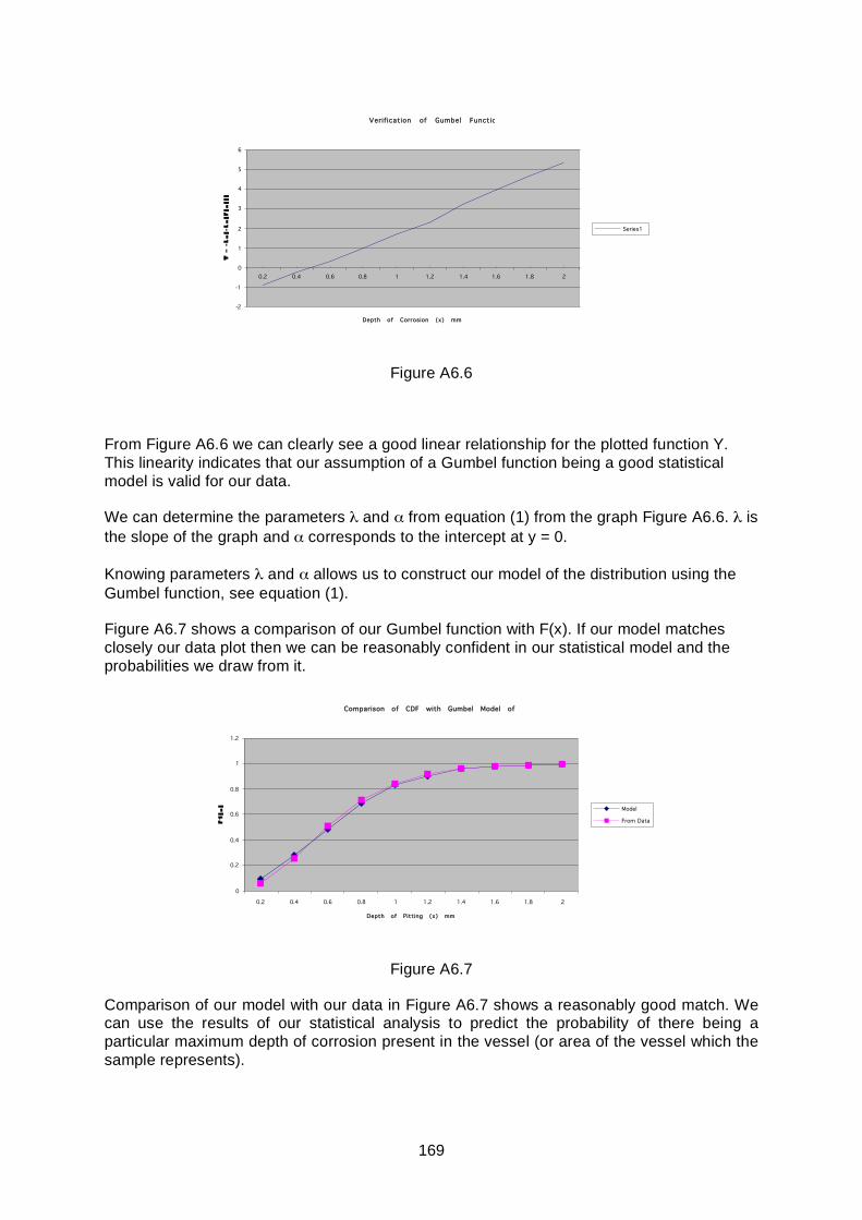
169
Verification of Gumbel Function
-2
-1
0
1
2
3
4
5
6
0.2 0.4 0.6 0.8 1 1.2 1.4 1.6 1.8 2
Depth of Corrosion (x) mm
Series1
Figure A6.6
From Figure A6.6 we can clearly see a good linear relationship for the plotted function Y. This linearity indicates that our assumption of a Gumbel function being a good statistical model is valid for our data.
We can determine the parameters λ and α from equation (1) from the graph Figure A6.6. λ is the slope of the graph and α corresponds to the intercept at y = 0.
Knowing parameters λ and α allows us to construct our model of the distribution using the Gumbel function, see equation (1).
Figure A6.7 shows a comparison of our Gumbel function with F(x). If our model matches closely our data plot then we can be reasonably confident in our statistical model and the probabilities we draw from it.
Comparison of CDF with Gumbel Model of F(x)
0
0.2
0.4
0.6
0.8
1
1.2
0.2 0.4 0.6 0.8 1 1.2 1.4 1.6 1.8 2
Depth of Pitting (x) mm
Model
From Data
Figure A6.7
Comparison of our model with our data in Figure A6.7 shows a reasonably good match. We can use the results of our statistical analysis to predict the probability of there being a particular maximum depth of corrosion present in the vessel (or area of the vessel which the sample represents).
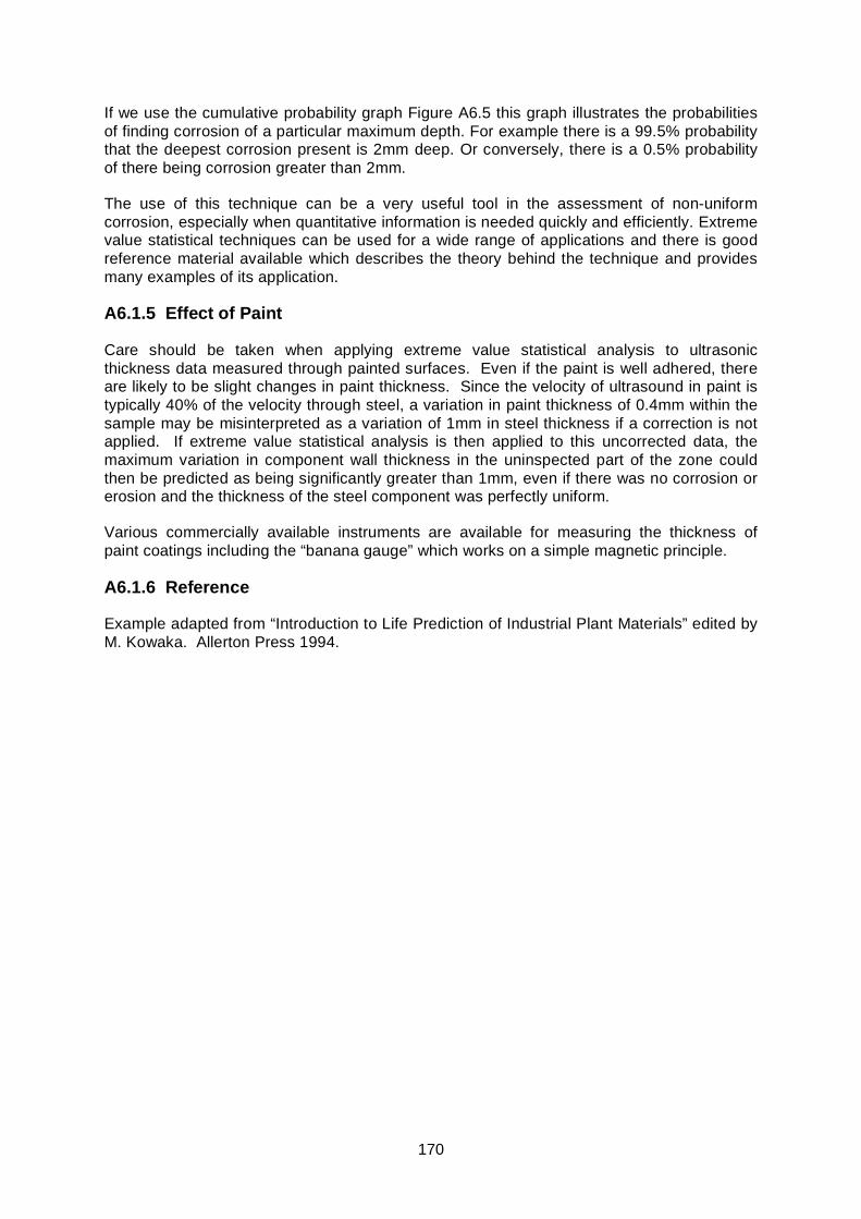
170
If we use the cumulative probability graph Figure A6.5 this graph illustrates the probabilities of finding corrosion of a particular maximum depth. For example there is a 99.5% probability that the deepest corrosion present is 2mm deep. Or conversely, there is a 0.5% probability of there being corrosion greater than 2mm.
The use of this technique can be a very useful tool in the assessment of non-uniform corrosion, especially when quantitative information is needed quickly and efficiently. Extreme value statistical techniques can be used for a wide range of applications and there is good reference material available which describes the theory behind the technique and provides many examples of its application.
A6.1.5 Effect of Paint
Care should be taken when applying extreme value statistical analysis to ultrasonic thickness data measured through painted surfaces. Even if the paint is well adhered, there are likely to be slight changes in paint thickness. Since the velocity of ultrasound in paint is typically 40% of the velocity through steel, a variation in paint thickness of 0.4mm within the sample may be misinterpreted as a variation of 1mm in steel thickness if a correction is not applied. If extreme value statistical analysis is then applied to this uncorrected data, the maximum variation in component wall thickness in the uninspected part of the zone could then be predicted as being significantly greater than 1mm, even if there was no corrosion or erosion and the thickness of the steel component was perfectly uniform.
Various commercially available instruments are available for measuring the thickness of paint coatings including the “banana gauge” which works on a simple magnetic principle.
A6.1.6 Reference
Example adapted from “Introduction to Life Prediction of Industrial Plant Materials” edited by M. Kowaka. Allerton Press 1994.
171
A6.2 PROBABILITY OF DETECTING AT LEAST ONE DEFECT AS A FUNCTION OF WELD DEFECTIVENESS AND SAMPLE SIZE.
Description Of Problem:
Assume a weld has a uniform random distribution of defects within its length. This random distribution can be represented as a percentage of defective weld structure. If a defect will be detected when the region it is in is inspected, the problem is to determine the probability of detecting at least 1 defect when only inspecting a percentage of the weld volume (and therefore e.g. being alerted to the fact that a particular degradation mechanism is active). This example assumes 100% detection capability. However in practice the Probability of Detection (PoD) of the technique used for the minimum size of defect to be detected is required, in order to assess both the inclusion and detection of a defect within the region inspected.
POI : Probability of Inclusion of a Defect
Cov : Percentage Coverage of the Weld Volume.
Dd : Defect Distribution as a Percentage
Assumptions:
To assist in calculating the POI the following assumptions are made:
The weld volume can be divided into 100 discrete units.
Probability that a unit contains a defect:
Pd = Dd / 100%.
Probability that a unit contains no defect:
P0 = 1 - Pd
Probability of Inclusion:
POI = 1-PON
Where
PON : Probability of Detecting No Defects
METHODS:
Using the above definitions and assumptions a number of models could be used to determine the POI:

172
Simple Evaluation:
Using the following data evaluation, a formula can be determined and extrapolated to 100% coverage.
Pd % 1 2 3 4
P0 % 99 98 97 96
Cov %
PON PON PON PON
0 1 1 1 1
1
10099
10098
10097
10096
2
9998
10099
! 9997
10098
! 9996
10097
! 9995
10096
!
3
9897
9998
10099
!! 9896
9997
10098
!! 9895
9996
10097
!! 9894
9995
10096
!!
4
9796
9897
9998
10099
!!! 9795
9896
9997
10098
!!! 9794
9895
9996
10097
!!! 9793
9894
9995
10096
!!!
General Formula
)!Cov100(!100
)!CovP100()!P100(
PON d
d
!
!!
!
=
Binomial Distribution:
rd
rn0 PP
!r)!rn(!n1PON1POI !!""
#
$%%&
'
((=(=
(
Where:
n = Cov
r = 0 defects to detect
By altering n from 0 to 100 % coverage the POI rises from 0 to 1 in a curve.
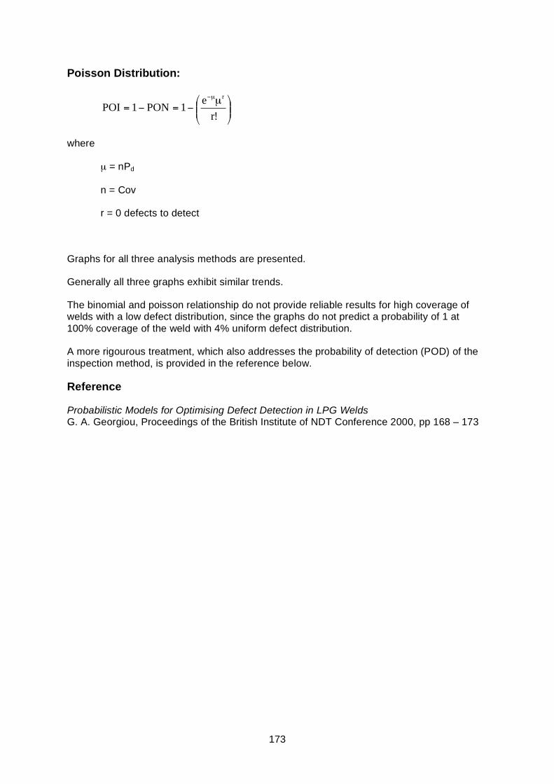
173
Poisson Distribution:
!!"
#$$%
& µ'='=
µ'
!re1PON1POI
r
where
µ = nPd
n = Cov
r = 0 defects to detect
Graphs for all three analysis methods are presented.
Generally all three graphs exhibit similar trends.
The binomial and poisson relationship do not provide reliable results for high coverage of welds with a low defect distribution, since the graphs do not predict a probability of 1 at 100% coverage of the weld with 4% uniform defect distribution.
A more rigourous treatment, which also addresses the probability of detection (POD) of the inspection method, is provided in the reference below.
Reference
Probabilistic Models for Optimising Defect Detection in LPG Welds G. A. Georgiou, Proceedings of the British Institute of NDT Conference 2000, pp 168 – 173
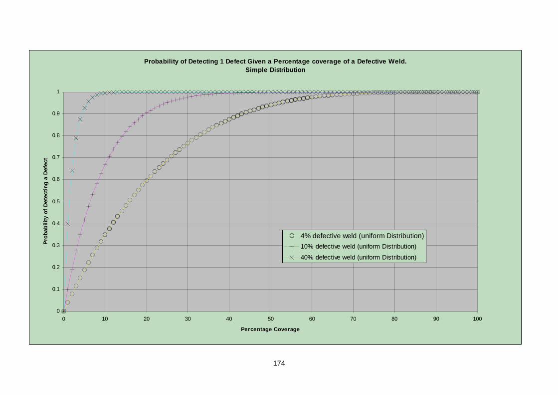
174
Probability of Detecting 1 Defect Given a Percentage coverage of a Defective Weld.Simple Distribution
0
0.1
0.2
0.3
0.4
0.5
0.6
0.7
0.8
0.9
1
0 10 20 30 40 50 60 70 80 90 100
Percentage Coverage
Prob
abili
ty o
f Det
ectin
g a
Def
ect
4% defective weld (uniform Distribution)10% defective weld (uniform Distribution)
40% defective weld (uniform Distribution)
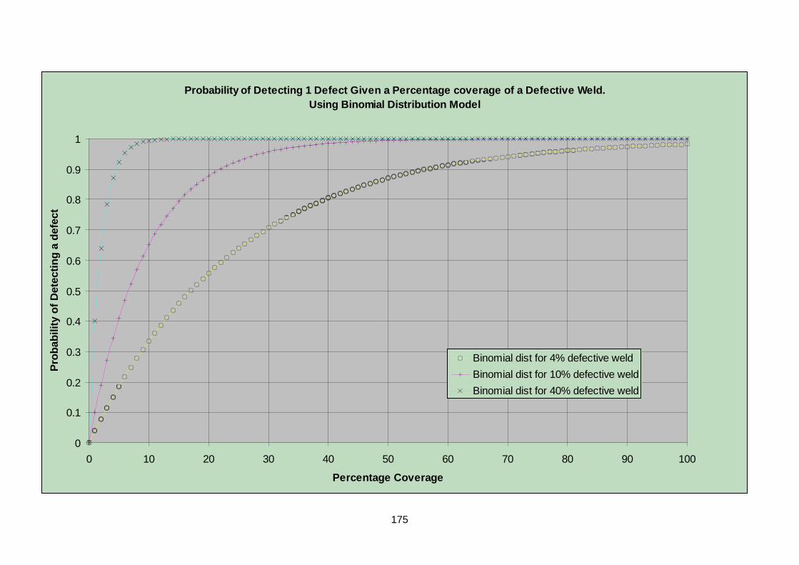
175
Probability of Detecting 1 Defect Given a Percentage coverage of a Defective Weld.Using Binomial Distribution Model
0
0.1
0.2
0.3
0.4
0.5
0.6
0.7
0.8
0.9
1
0 10 20 30 40 50 60 70 80 90 100
Percentage Coverage
Prob
abili
ty o
f Det
ectin
g a
defe
ct
Binomial dist for 4% defective weldBinomial dist for 10% defective weldBinomial dist for 40% defective weld
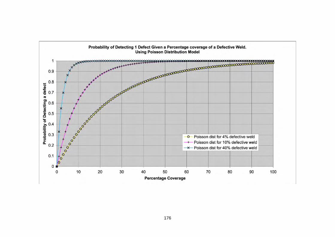
176

177

Published by the Health and Safety Executive 01/09

Evaluation of the effectiveness of non-destructive testing screening methods for in-service inspection
Health and Safety Executive
RR659
www.hse.gov.uk
A wide range of engineering plant is subject to periodic in-service inspection in order to ensure continued safe and economic operation. The inspections are often performed by traditional NDT methods such as routine ultrasonics, magnetic particle inspection, dye penetrant inspection, visual inspection and radiography. These can be highly sensitive but the rate of coverage is often slow, so that full coverage can be prohibitively expensive, and extensive preparation for inspection may be required (eg access for internal visual inspection, removal of insulation for external inspection etc.) There are also many situations where geometry or access prevents the use of conventional inspection methods.
Over recent years a wide range of advanced NDT techniques has evolved. These techniques provide large area screening of a component for significant degradation. Some of the techniques can be rapidly applied, much quicker than a more detailed, conventional inspection. Generally, the screening techniques are less sensitive than the more traditional methods. They also provide a means of inspecting areas which would otherwise be ‘uninspectable’. Examples include long range ultrasonics, pulsed eddy current techniques and saturated low frequency eddy current techniques.
There is a lack of objective information on the capability and limitations of screening techniques which is needed in order to allow judgement on their suitability for a particular application. Guidance is required on how to select a particular technique, what it can detect (as well as what it can miss), and what the level of confidence is in no degradation being present if none is detected.
The aim of this document is to provide an objective source of information on the capability and limitations of screening techniques and to provide information on their use to those involved in plant operation and maintenance.
This report and the work it describes were funded by the Health and Safety Executive (HSE). Its contents, including any opinions and/or conclusions expressed, are those of the author alone and do not necessarily reflect HSE policy.