Embed Size (px)
Citation preview

RS-485: The Industrial Workhorse’s Design Guide
RS-485 crash course
Principles, Design-hints, Transceivers
1
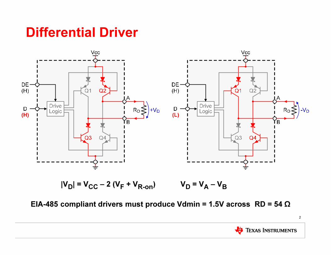
Differential Driver
2
|VD| = VCC – 2 (VF + VR-on) VD = VA – VB
EIA-485 compliant drivers must produce Vdmin = 1.5V across RD = 54 Ω

Output Characteristics
3
5.0
4.5
4.0
3.5
3.0
2.5
2.0
1.5
1.0
0.5
00 20 40 60 80
IO – Driver Output Current – mA
VOH
,VOL
–D
riv
er
Ou
tpu
t V
olt
ag
e –
V
10 30 50 70 90
5V Driver
3.3V Driver
VOH
VOL
VOL
VOH
5.0
4.5
4.0
3.5
3.0
2.5
2.0
1.5
1.0
0.5
00 20 40 60 80
IO – Driver Output Current – mA
VOD
–D
iffe
ren
tia
l D
rive
r O
utp
ut
Vo
lta
ge
–V
10 30 50 70 90
5V Driver
3.3V Driver
RS-485 compliant drivers must produce VD-min ≥ 1.5V across RD = 54 Ω
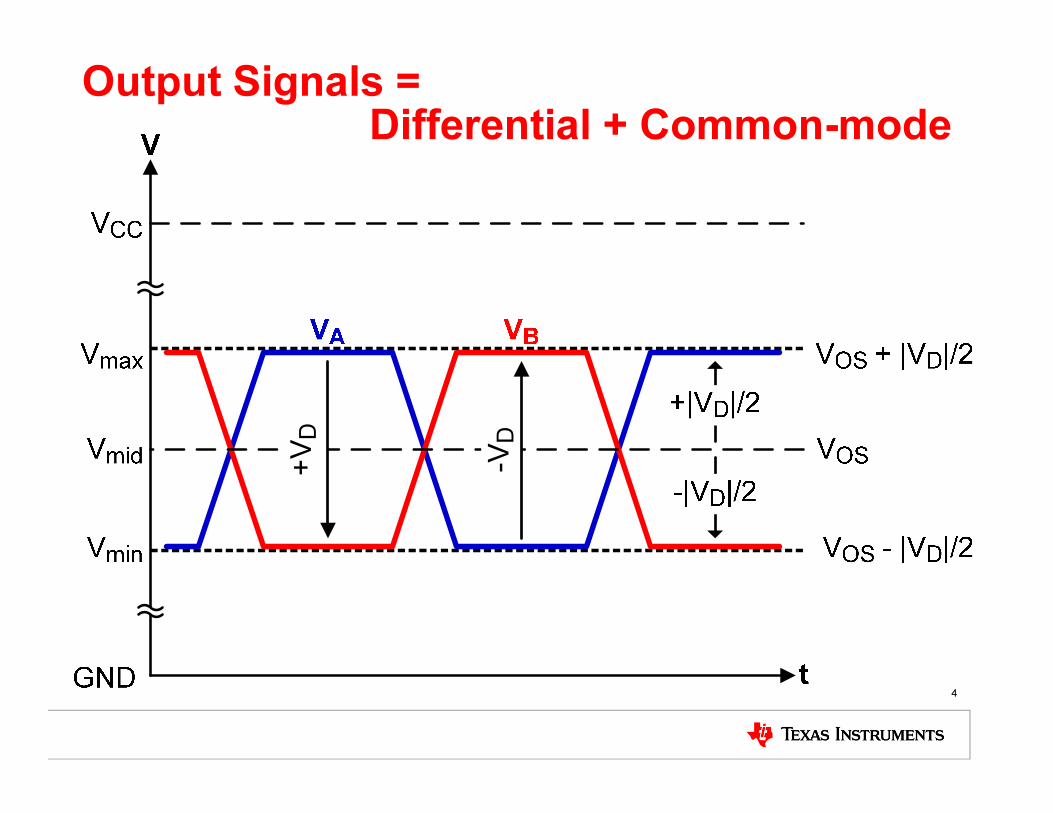
Output Signals = Differential + Common-mode
4
+VD
-VD

Driver Model with VOS and VD/2
5
The driver can be modelled with a bias voltage of VOSsuperimposed by two differential voltages of VD/2
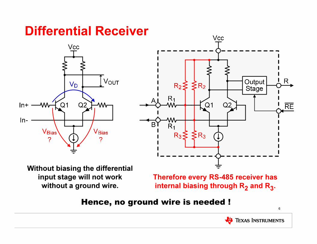
Differential Receiver
6
Without biasing the differential
input stage will not work
without a ground wire.Therefore every RS-485 receiver has
internal biasing through R2 and R3.
Hence, no ground wire is needed !

Bus Terminals Equivalent Circuit Diagram
7
The protection diodes,
shown separately in data
sheets, are in fact one
and the same SCRs.
Vcc
R2
R1
B
RCV
Vcc
A
R3
R
R2
R3
R1
Drive
Logic
DE
D
DRV
GND
1
2
3
4
5
8
7
6
RE
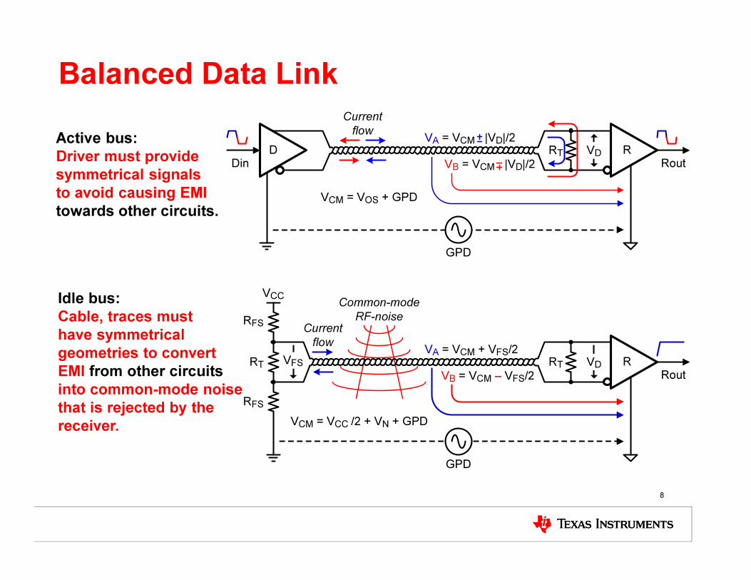
Balanced Data Link
8
Rout
GPD
VCM = VOS + GPD
VD RDin
D RT
Current
flowVA = VCM |VD|/2
VB = VCM |VD|/2
GPD
VCM = VCC /2 + VN + GPD
VD RRT
Current
flowVA = VCM + VFS/2
RT
RFS
RFS
VCC
VFS
VB = VCM – VFS/2
Common-mode
RF-noise
Rout
Active bus:
Driver must provide
symmetrical signals
to avoid causing EMI
towards other circuits.
Idle bus:
Cable, traces must
have symmetrical
geometries to convert
EMI from other circuits
into common-mode noise
that is rejected by the
receiver.
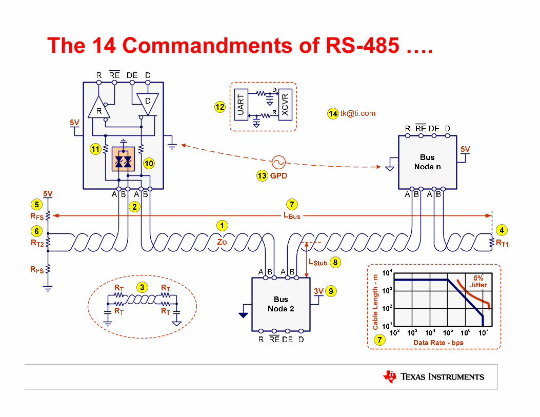
The 14 Commandments of RS-485 +.
UART
XCVR
Ca
ble
Le
ng
th -
m
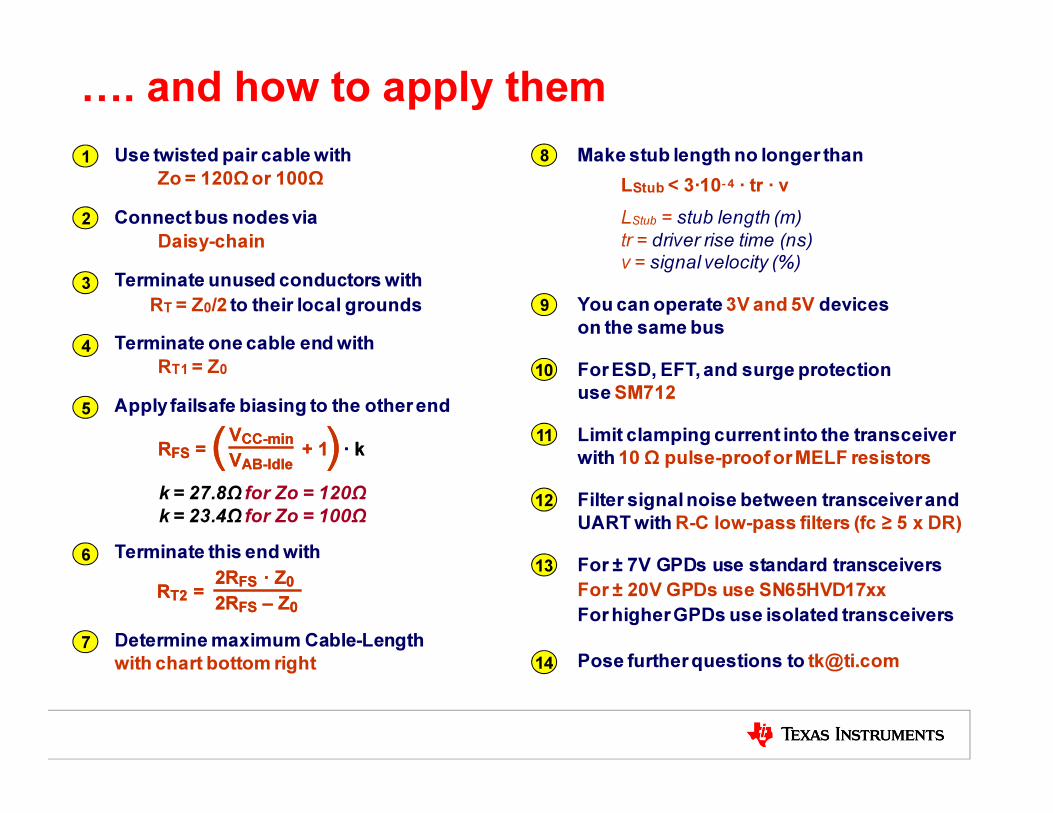
+. and how to apply them
7 Determine maximum Cable-Length
with chart bottom right
1 Use twisted pair cable with
Zo = 120Ω or 100Ω
4 Terminate one cable end with
RT1 = Z0
3 Terminate unused conductors with
to their local groundsRT = Z0/2
5 Apply failsafe biasing to the other end
k = 27.8Ω for Zo = 120Ω
k = 23.4Ω for Zo = 100Ω
RFS = + 1 · k)(VCC-min
VAB-Idle
RFS = + 1 · k)(VCC-min
VAB-Idle
6 Terminate this end with
RT2 =2RFS · Z0
2RFS – Z0RT2 =
2RFS · Z0
2RFS – Z0
2 Connect bus nodes via
Daisy-chain
9 You can operate 3V and 5V devices
on the same bus
13 For ± 7V GPDs use standard transceivers
For ± 20V GPDs use SN65HVD17xx
For higher GPDs use isolated transceivers
8
LStub < 3·10- 4 · tr · v
LStub = stub length (m)
tr = driver rise time (ns)v = signal velocity (%)
Make stub length no longer than
14 Pose further questions to [email protected]
10 For ESD, EFT, and surge protection
use SM712
11 Limit clamping current into the transceiver
with 10 Ω pulse-proof or MELF resistors
12 Filter signal noise between transceiver and
UART with R-C low-pass filters (fc ≥ 5 x DR)

1) Use twisted pair cable
11
Belden Wire and Cable Company, www.belden.com
CommScope, www.commscope.com
General Cable Corporation, www.generalcable.com
Madison Cable Corporation, www.madisoncable.com
Handbook of Wiring, Cabling, and Interconnecting for Electronics,
Charles A. Harper, ed., McGraw-Hill, New York, 1972.
Introduction to Copper Cabling,
John Crisp, Newnes (Elsevier Science), Oxford, 2002.
Cable:
Type:
Impedance:
Capacitance:
DC-Resistance:
Velocity:
Belden 3105A
1-pairy, 22 AWG, PLCT/CM
120 Ω
11 pF/ft
14.7 mΩ/ft
78% (1.3 ns/ft)
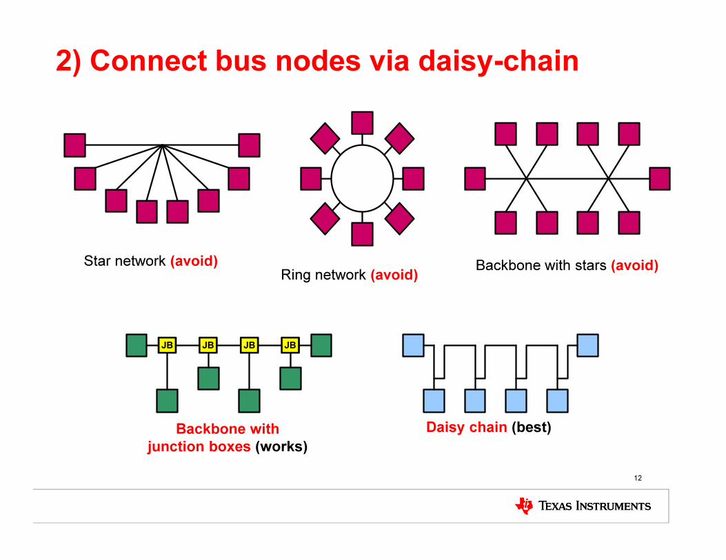
2) Connect bus nodes via daisy-chain
12
Backbone with
junction boxes (works)
Backbone with stars (avoid)Star network (avoid)Ring network (avoid)
Daisy chain (best)
JB JB JB JB
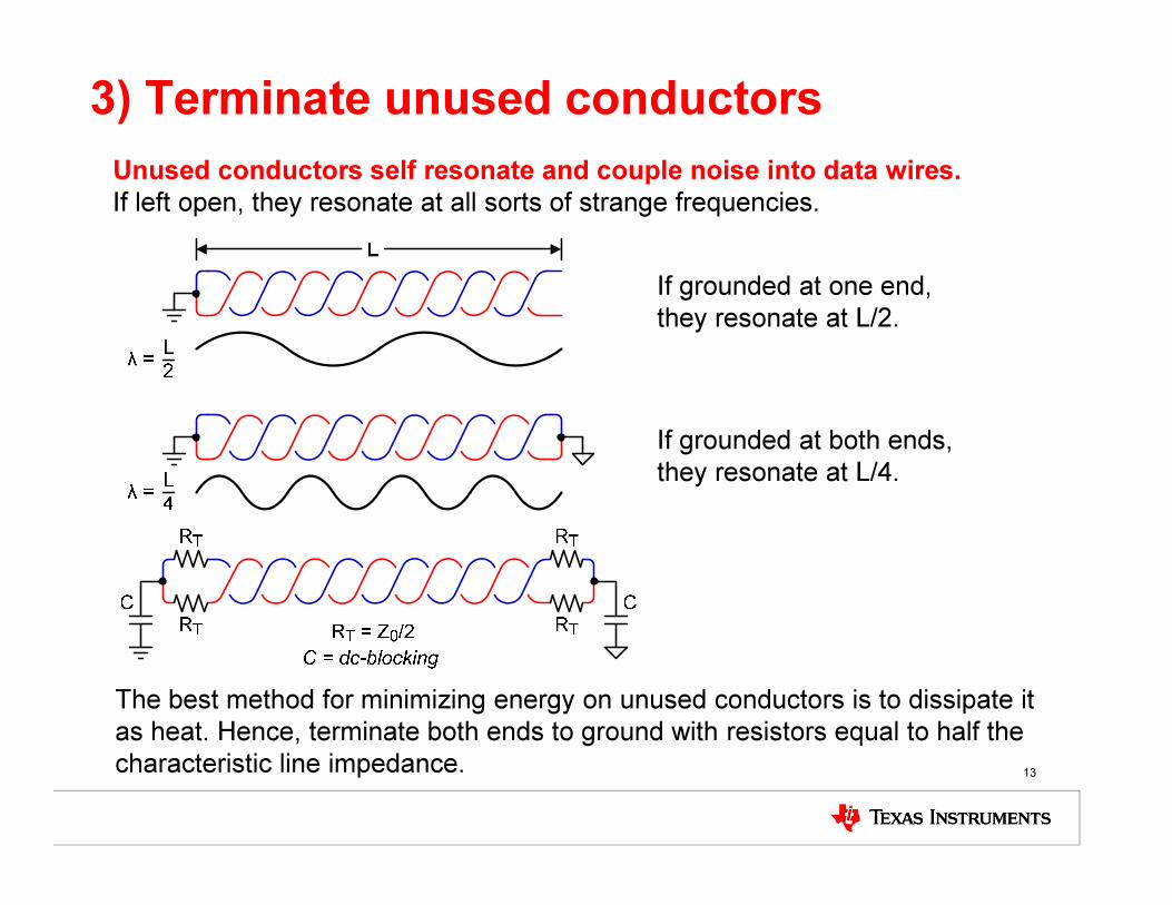
3) Terminate unused conductors
13
If grounded at one end,
they resonate at L/2.
Unused conductors self resonate and couple noise into data wires.
If left open, they resonate at all sorts of strange frequencies.
The best method for minimizing energy on unused conductors is to dissipate it
as heat. Hence, terminate both ends to ground with resistors equal to half the
characteristic line impedance.
If grounded at both ends,
they resonate at L/4.

4,5,6) Apply termination and failsafe biasing
14
VBus-min = minimum bus supply voltage
VAB = 200mV + VNoise
Z0 = 120Ω
RFS
549 Ω
RFS
549 Ω
RT2
133 ΩRT1
120 Ω
RT2
=2 R
FS· Z
0
2 RFS
– Z0)
RFS
=Vbus-min
VAB
1
(1/375 + 4/Z0)
+1( ) ·
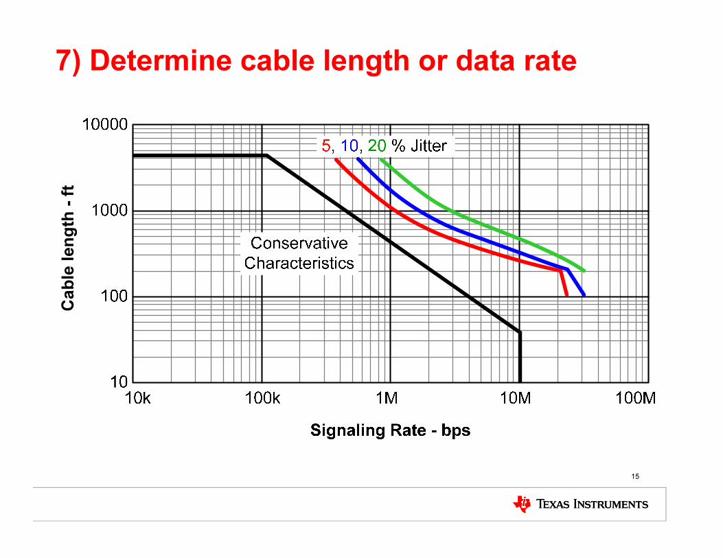
7) Determine cable length or data rate
15
Ca
ble
len
gth
-ft

8) Minimize stub length
16
c10
tL
r
Stub⋅ν⋅≤
LStub
= maximum stub length (ft)
tr= driver (10/90) rise time (ns)
v = signal velocity of the cable as factor of c
c = speed of light (9.8 ·108 ft/s)
DeviceSignal rate
[Mbps]
Rise time
tr [ns]
Max. Stub
length [ft]
SN65HVD1176 40 2 0.15
SN65HVD21 5 20 1.5
SN65HVD12 1 100 7.6
SN65LBC184 0.25 250 19
SN65HVD3082E 0.2 500 38
A stub is a piece of unterminated transmission line, whose electrical
length (signal propagation time) should be less then 1/10 the fastest
signal transition on the bus (the driver rise/fall time).

8b) Distinguish between stub types
17
Daisy Chain
Junction
Boxes
LStub
LStub
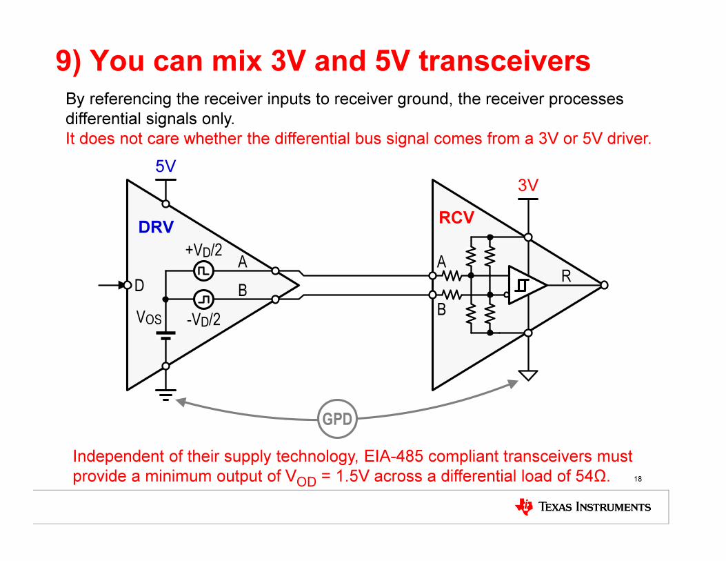
9) You can mix 3V and 5V transceivers
18
By referencing the receiver inputs to receiver ground, the receiver processes
differential signals only.
It does not care whether the differential bus signal comes from a 3V or 5V driver.
VOS
+VD/2
B
RCV
3V
AR
5V
D
-VD/2
A
B
DRV
GPD
Independent of their supply technology, EIA-485 compliant transceivers must
provide a minimum output of VOD
= 1.5V across a differential load of 54Ω.

10,11) Apply transient protection
19
Internal
SCR
External
TVS
Without Rs the
SCR can shunt the
TVS and turn it off!
The preferred TVS is SM712 with breakdown
voltages from -7V to +12V (EIA-485 compliant).
Rs should be 5Ω to 10Ω MELF or
pulse-proof thickfilm resistors.
(available from Vishay)
(available from Semtech, Bourns, Protek Devices)
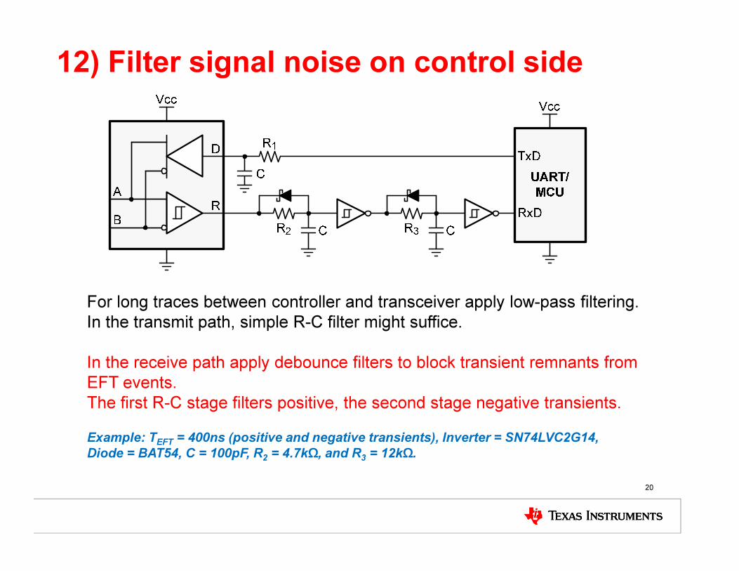
12) Filter signal noise on control side
20
For long traces between controller and transceiver apply low-pass filtering.
In the transmit path, simple R-C filter might suffice.
In the receive path apply debounce filters to block transient remnants from
EFT events.
The first R-C stage filters positive, the second stage negative transients.
Example: TEFT = 400ns (positive and negative transients), Inverter = SN74LVC2G14,
Diode = BAT54, C = 100pF, R2 = 4.7kΩ, and R3 = 12kΩ.

13) Handle ground potential differences
21
ISO
ISO
Common-mode voltage range - V
HVD2x, HVD17xx
transceivers
LBC184, HVD308x,
HVD7x, HVD8x
transceivers
ISO3080/82, ISO35/15, ISO3086/88, ISO1176
ISO35T, ISO3086T, ISO1176T
transceivers
T = integrated transformer driver

Applications and suggested transceivers
22
Tolerating cross-wire faults :(E-metering and longhaul networks)
High-speed data over long distance:(Encoders, seismic, traffic monitoring)
High-speed data, high ESD/EFT:(Backplanes)
High ESD/EFT, long distance:(Factory and building automation)
Lightning protection:(Industrial networks)
Running data adjacent to power cable:(Factory and building automation)
Selecting low/high data rates at 1.8 Vcc:(Telecom linecards)
Isolated bus nodes:(Profibus networks)
SN65HVD888
SN65HVD23 / 24
SN65HVD75 / 78
SN65HVD72 / 82
SN65LBC184
SN65HVD17xx
SN65HVD01
ISO1176T

• Automatic polarity correction
• IEC ESD protection
• ±16kV HBM protection
• ±12kV IEC61000-4-2 Contact Discharge
• +4kV IEC61000-4-4 Fast Transient Burst
• Low quiescent supply current (<1 mA) &
Low Standby Supply Current: (< 1 uA typ)
• Large Receiver Hysteresis (60 mV)
• Up to 256 Nodes on a Bus
• Standard SOIC-8 package
• Prevents system failure in case of mis-wiring
• Reliable in high noise environments
• Enables system power savings → suitable for
low power applications.
• Immunity to noise signals on the bus lines
• Allows many nodes on a single network
• Drop-in replacement for industry standard
parts
Applications
• E-Metering Networks
• Industrial Automation
• HVAC Systems
• DMX512-Networks
• Process Control
• Battery-Powered Applications
Features Benefits
SN65HVD8885V, 250kbps, RS485 w/ automatic polarity correction
TI Confidential – NDA Restrictions
Part # Data Rate Duplex Package
SN65HVD888 250kbps Half SOIC-8
POLCOR

• Low EMI Receiver Equalization
• Common-mode voltage range
(-20V to +25V)
• Bus I/O protection to over 16kV HBM
• Failsafe receiver (open / short / idle)
• More than 100mV receiver hysteresis
• Standby current ≤ 1 µA
Applications
• Long-cable solutions
Building automation
Security networks
Features
Benefits
SN65HVD23/24Wide Common-mode transceivers with receiver Equalization
• Improves jitter performance
on longhaul bus
• Low-cost Network extension
• Low-cost Bandwidth
increase
TI Confidential – NDA Restrictions
Part # Data Rate Cable
Length
Nodes Package
SN65HVD23 25Mbps 160m Up to 64 SOIC-8/PDIP-8
SN65HVD24 3Mbps 500m Up to 256 SOIC-8/PDIP-8
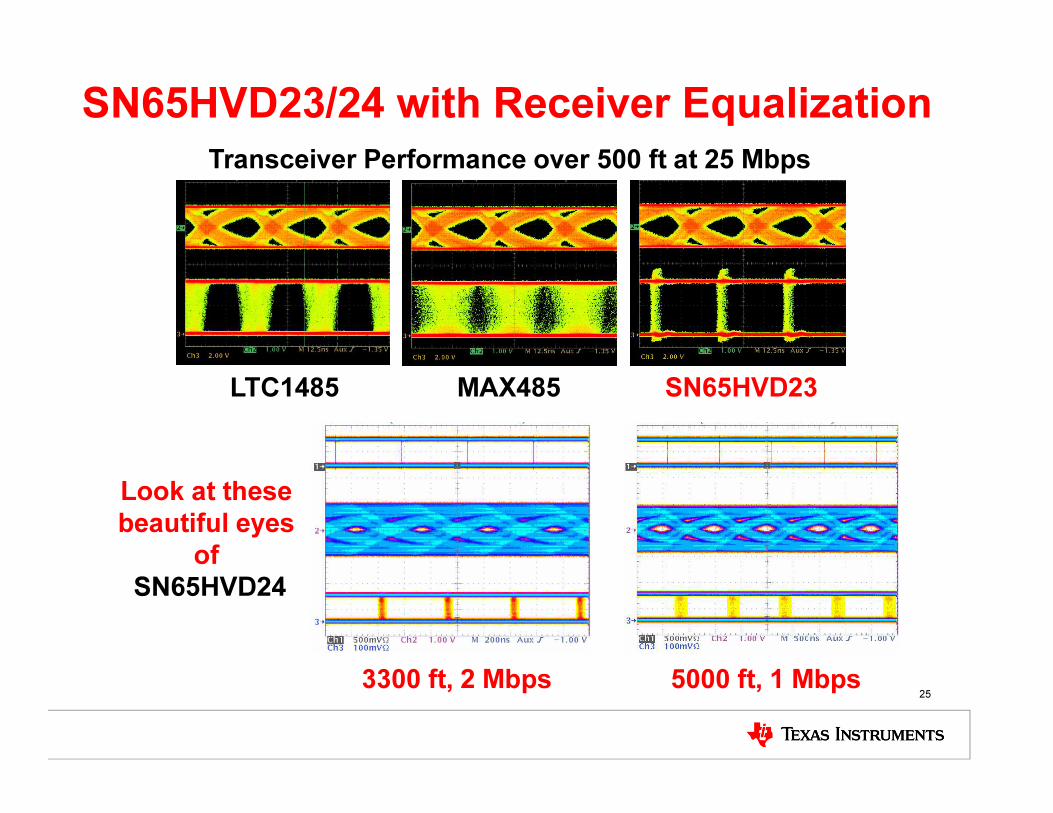
SN65HVD23/24 with Receiver Equalization
25
Transceiver Performance over 500 ft at 25 Mbps
SN65HVD23MAX485LTC1485
3300 ft, 2 Mbps 5000 ft, 1 Mbps
Look at these
beautiful eyes
of
SN65HVD24
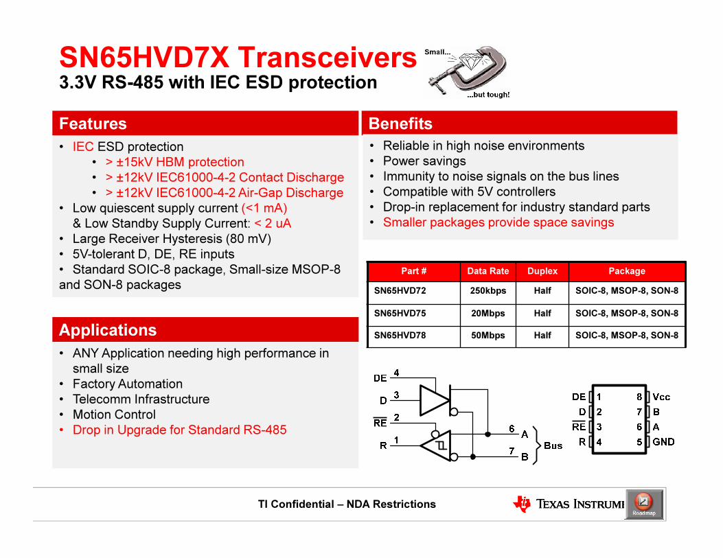
• IEC ESD protection
• > ±15kV HBM protection
• > ±12kV IEC61000-4-2 Contact Discharge
• > ±12kV IEC61000-4-2 Air-Gap Discharge
• Low quiescent supply current (<1 mA)
& Low Standby Supply Current: < 2 uA
• Large Receiver Hysteresis (80 mV)
• 5V-tolerant D, DE, RE inputs
• Standard SOIC-8 package, Small-size MSOP-8
and SON-8 packages
Applications
• ANY Application needing high performance in
small size
• Factory Automation
• Telecomm Infrastructure
• Motion Control
• Drop in Upgrade for Standard RS-485
Features Benefits
SN65HVD7X Transceivers3.3V RS-485 with IEC ESD protection
• Reliable in high noise environments
• Power savings
• Immunity to noise signals on the bus lines
• Compatible with 5V controllers
• Drop-in replacement for industry standard parts
• Smaller packages provide space savings
TI Confidential – NDA Restrictions
Part # Data Rate Duplex Package
SN65HVD72 250kbps Half SOIC-8, MSOP-8, SON-8
SN65HVD75 20Mbps Half SOIC-8, MSOP-8, SON-8
SN65HVD78 50Mbps Half SOIC-8, MSOP-8, SON-8
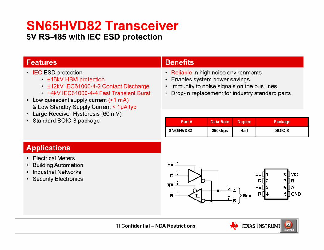
• IEC ESD protection
• ±16kV HBM protection
• ±12kV IEC61000-4-2 Contact Discharge
• +4kV IEC61000-4-4 Fast Transient Burst
• Low quiescent supply current (<1 mA)
& Low Standby Supply Current < 1µA typ
• Large Receiver Hysteresis (60 mV)
• Standard SOIC-8 package
Applications
• Electrical Meters
• Building Automation
• Industrial Networks
• Security Electronics
Features Benefits
SN65HVD82 Transceiver5V RS-485 with IEC ESD protection
• Reliable in high noise environments
• Enables system power savings
• Immunity to noise signals on the bus lines
• Drop-in replacement for industry standard parts
TI Confidential – NDA Restrictions
Part # Data Rate Duplex Package
SN65HVD82 250kbps Half SOIC-8
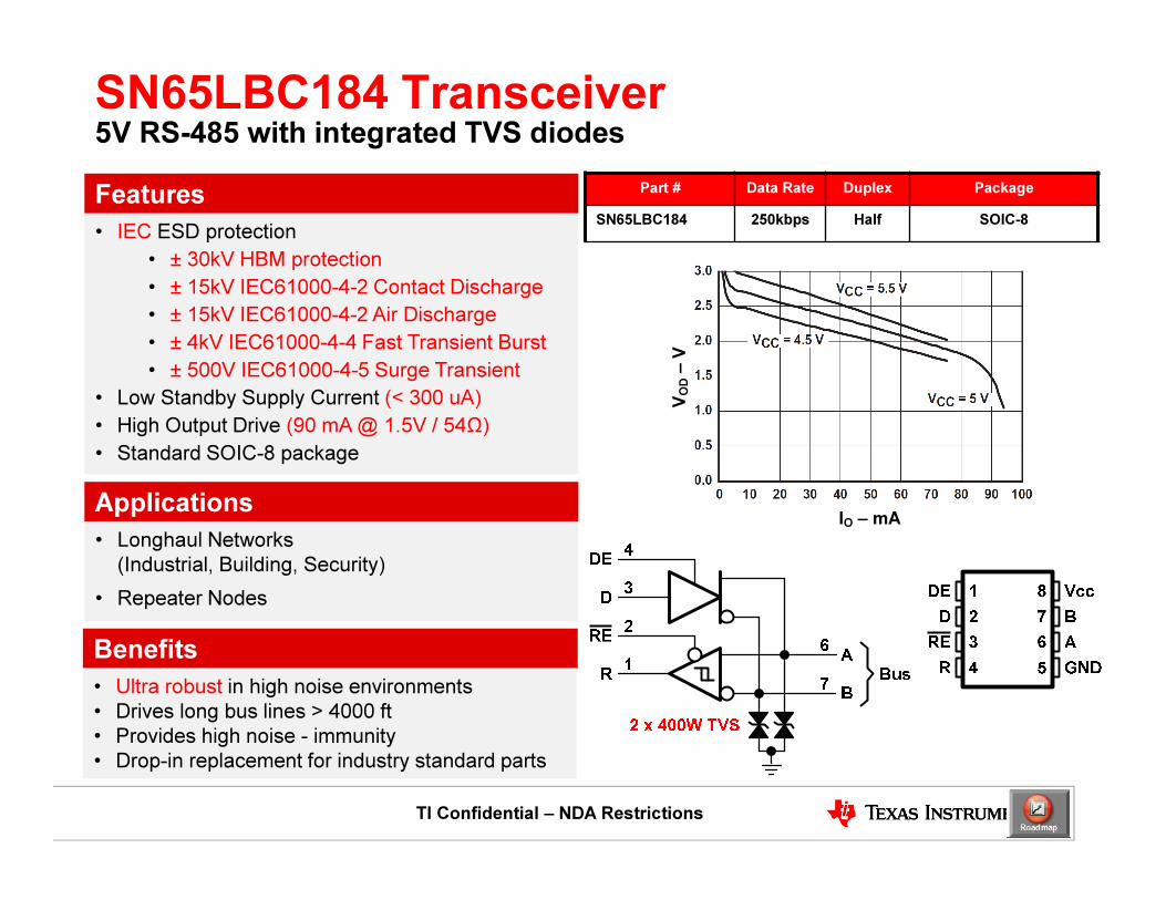
• IEC ESD protection
• ± 30kV HBM protection
• ± 15kV IEC61000-4-2 Contact Discharge
• ± 15kV IEC61000-4-2 Air Discharge
• ± 4kV IEC61000-4-4 Fast Transient Burst
• ± 500V IEC61000-4-5 Surge Transient
• Low Standby Supply Current (< 300 uA)
• High Output Drive (90 mA @ 1.5V / 54Ω)
• Standard SOIC-8 package
Applications
• Longhaul Networks
(Industrial, Building, Security)
• Repeater Nodes
Features
Benefits
SN65LBC184 Transceiver5V RS-485 with integrated TVS diodes
• Ultra robust in high noise environments
• Drives long bus lines > 4000 ft
• Provides high noise - immunity
• Drop-in replacement for industry standard parts
TI Confidential – NDA Restrictions
Part # Data Rate Duplex Package
SN65LBC184 250kbps Half SOIC-8
VOD
–V
IO – mA

• Bus-pin fault protection up to ±70V
• -20V to +25V Common mode operation
• 3V to 5V VCC operation
• Bus ESD Protection +16kV JEDEC HBM
• Up to 256 or 320 Nodes
• Failsafe Receiver (Open, Shorted, Idle)
• Low Power - 6 mA Active / 5 µA Shutdown
• Glitch−Free Power−Up/Down
Applications
• ANY Application with potential to shorten
up to ±70 V to bus lines!
Drop in Upgrade for Standard RS485
Features Benefits
SN65HVD17xxWide Common-mode transceivers with ±70V Stand-off
• Ultra High reliability Harshest conditions
• Over voltage protection to ±70V
• No termination needed for protection!!
• Wide Common for large ground differences
• Wide VCC Range of operation
• High ESD Protection added survivability
• Hot pluggable without data Corruption
• Versions for all Applications
TI Confidential – NDA Restrictions
Part # Data Rate Duplex Features Package
SN65HVD1780 115kbps Half 3V to 5V VCC SOIC-8/PDIP-8
SN65HVD1781 1Mbps Half 3V to 5V VCC SOIC-8/PDIP-8
SN65HVD1782* 10Mbps Half 3V to 5V VCC SOIC-8/PDIP-8
SN65HVD1785 115kbps Half 5V VCC, -20V to 25V CM SOIC-8/PDIP-8
SN65HVD1786 1Mbps Half 5V VCC, -20V to 25V CM SOIC-8/PDIP-8
SN65HVD1787* 10Mbps Half 5V VCC, -20V to 25V CM SOIC-8/PDIP-8
SN65HVD1791 115kbps Full 5V VCC, -20V to 25V CM SOIC-14
SN65HVD1792 1Mbps Full 5V VCC, -20V to 25V CM SOIC-14
SN65HVD1793* 10Mbps Full 5V VCC, -20V to 25V CM SOIC-14
SN65HVD1794 115kbps Half 5V VCC, -20V to 25V CM,
Cable Invert
SOIC-8

• Low-voltage Input/Output supply
• Small package (3mm x 3mm SON)
• Switchable signaling rate (250 kbps or 20 Mbps)
• High receiver hysteresis (50 mV minimum)
• Low-power standby mode (100 nA typical)
• VL = 1.65V – 3.6V, VCC = 3.0V – 3.6V
Applications
• Telecommunications equipment
• Point-of-sales terminals
• Portable industrial equipment
Features Benefits
SN65HVD01: 3.3V RS-485 with Low-Voltage I/O and Switchable Signaling Rate
• Interface with low-voltage micro-controllers
• Saves board space
• Optimize for slow & long network, or fast network
• Immune to differential-mode noise
• Use in battery-powered systems, or wherever
power consumption is critical
30

• Integrated Design• SiO2Dielectric Capacitor and Transformer Driver
• IBus-Pin ESD Protection:
• >10kV GND2
• 6kV GND1
• 1Mbps / 20Mbps / 40Mbps
• 1/8 Unit load – 256 nodes on a bus
• Glitch-Free & Failsafe (Open, Shorted, Idle)
• Immunity and Certifications• Meets or Exceeds TIA/EIA RS-485
• 2500Vrms Withstand, 560Vpk Working Voltages
- UL1577, IEC 60747-5-2 (VDE 0884, rev. 2),
IEC 61010-1 & CSA pending
Applications
• Energy Meter Networks
• Power Inverters
• Industrial Automation
• Building Automation Networks
• Motor Control
• HVAC
Features Benefits
ISO RS-485 with Transformer Driver
• Ease of isolated power design
• Fully compliant to RS-485 Standard
• High Reliability in Harsh Environments
• Optimized for Long Cables Or High Speed
• Large buses
• Hot pluggable & Protected in all situations
• Proven Reliability of SiO2 Insulation, Stable over
Time, Temperature & Moisture
- Life Span > 25 years @ 125oC
TI Confidential – NDA Restrictions
Part # Duplex Function Speed Package
ISO1176T Half Profibus 40Mbps SOIC-16 (DW)
ISO35T Full 3.3V RS485 1Mbps SOIC-16 (DW)
ISO3086T Full 5V RS485 20Mbps SOIC-16 (DW)
EVM – ISO1176TEVM / ISO35TEVM / ISO3086TEVM