Embed Size (px)
Citation preview
R&S®TSMA6-BPR&S®TSMA6B-BPBattery Pack UnitGetting Started
Gettin
g Star
ted
Versi
on 05
4900903002(a0èN2)
This manual describes the following R&S®TSMA6 accessory:● R&S®TSMA6-BP Battery Pack Unit (4900.9001.02)● R&S®TSMA6B-BP Battery Pack Unit (4900.9001.20)● R&S MNT®BP89WH Batteries (1321.3772.00) for R&S®TSMA6-BP● R&S®MNT-BP99WH Batteries (3660.9109.02) for R&S®TSMA6B-BP
© 2020 Rohde & Schwarz GmbH & Co. KGMühldorfstr. 15, 81671 München, GermanyPhone: +49 89 41 29 - 0Email: [email protected]: www.rohde-schwarz.comSubject to change – Data without tolerance limits is not binding.
R&S® is a registered trademark of Rohde & Schwarz GmbH & Co. KG.Trade names are trademarks of the owners.
4900.9030.02 | Version 05 | R&S®TSMA6-BP R&S®TSMA6B-BP
Throughout this manual, products from Rohde & Schwarz are indicated without the ® symbol , e.g.R&S®TSMA6 is indicated as R&S TSMA6.
ContentsR&S®TSMA6-BP R&S®TSMA6B-BP
3Getting Started 4900.9030.02 ─ 05
Contents1 Safety Information................................................................. 5
2 Documentation Overview......................................................62.1 Getting Started Manual.........................................................................6
2.2 Basic Safety Instructions..................................................................... 6
2.3 Li-Ion Batteries Safety Instruction...................................................... 6
2.4 Data Sheets and Brochures................................................................. 6
3 Key Features.......................................................................... 8
4 Preparing for Use...................................................................94.1 Unpacking the Instrument..................................................................10
4.1.1 Hardware.............................................................................................. 10
4.1.2 Standard Accessory.............................................................................. 11
4.1.3 Optional Accessory............................................................................... 12
4.2 Connecting with External Power Supply and Charging the Batter-ies......................................................................................................... 12
4.3 Connecting the R&S TSMA6/6B-BP with R&S TSMA6.................... 14
4.4 Connecting the R&S TSMA6/6B-BP with R&S TSME6 and Down-converter R&S TSMExxDC.................................................................17
4.5 Connecting the R&S TSMA6/6B-BP with Multiple Devices.............19
4.6 Disconnecting the R&S TSMA6/6B-BP from R&S TSMx Devices.............................................................................................................. 25
5 Operation..............................................................................275.1 Operation Modes.................................................................................27
5.2 Power On/Off....................................................................................... 27
5.2.1 Auto Power On......................................................................................27
5.2.2 Standby.................................................................................................28
ContentsR&S®TSMA6-BP R&S®TSMA6B-BP
4Getting Started 4900.9030.02 ─ 05
5.3 Battery Charging.................................................................................28
5.4 Power Path Switching........................................................................ 28
5.5 Monitoring Battery Charge State.......................................................28
5.5.1 Battery Charge Display......................................................................... 29
5.5.2 Rear Panel LEDs.................................................................................. 30
5.5.3 R&S TSMA6 web-GUI / Tray Icon (Only Host-Controlled Mode)..........32
5.6 Battery Exchange - Hot Swapping.................................................... 32
6 Contacting Customer Support........................................... 35
Index..................................................................................... 36
Safety InformationR&S®TSMA6-BP R&S®TSMA6B-BP
5Getting Started 4900.9030.02 ─ 05
1 Safety InformationThe product documentation helps you use the R&S TSMA6/6B-BP safely and effi-ciently. Follow the instructions provided here and in the printed "Basic SafetyInstructions". Keep the product documentation nearby and offer it to other users.
Intended use
The R&S TSMA6/6B-BP is intended for the development, production and verifica-tion of electronic components and devices in industrial, administrative, and labo-ratory environments. Use the R&S TSMA6/6B-BP only for its designated purpose.Observe the operating conditions and performance limits stated in the data sheet.
Where do I find safety information?
Safety information is part of the product documentation. It warns you about thepotential dangers and gives instructions how to prevent personal injuries or dam-age caused by dangerous situations. Safety information is provided as follows:● The printed "Basic Safety Instructions" provide safety information in many lan-
guages and are delivered with the R&S TSMA6/6B-BP.● Throughout the documentation, safety instructions are provided when you
need to take care during setup or operation.
Documentation OverviewR&S®TSMA6-BP R&S®TSMA6B-BP
6Getting Started 4900.9030.02 ─ 05
2 Documentation OverviewThis section provides an overview of the R&S TSMA6/6B-BP user documenta-tion. Unless specified otherwise, you find the documents on the R&S TSMA6/6B-BP product page at:
www.rohde-schwarz.com/manual/tsmx
2.1 Getting Started Manual
Introduces the R&S TSMA6/6B-BP and describes how to set up and start workingwith the product. Includes basic operations, typical measurement examples, andgeneral information, e.g. safety instructions, etc. A printed version is deliveredwith the instrument.
2.2 Basic Safety Instructions
Contains safety instructions, operating conditions and further important informa-tion. The printed document is delivered with the instrument.
2.3 Li-Ion Batteries Safety Instruction
Contains safety instructions, operating conditions and further important informa-tion. The printed document is delivered with the instrument.
2.4 Data Sheets and Brochures
The data sheet contains the technical specifications of the R&S TSMA6/6B-BP. Italso lists optional accessories.
The brochure provides an overview of the instrument and deals with the specificcharacteristics.
Data Sheets and Brochures
Documentation OverviewR&S®TSMA6-BP R&S®TSMA6B-BP
7Getting Started 4900.9030.02 ─ 05
See www.rohde-schwarz.com/brochure-datasheet/tsmx
Data Sheets and Brochures
Key FeaturesR&S®TSMA6-BP R&S®TSMA6B-BP
8Getting Started 4900.9030.02 ─ 05
3 Key FeaturesThis manual describes two models of the battery pack.● R&S TSMA6-BP● R&S TSMA6B-BP
If descriptions in this manual are valid for both models, the termR&S TSMA6/6B-BP is used.
The R&S TSMA6/6B-BP enhances the R&S TSMA6 device to a portable mea-surement solution based on a battery powered system.
Key Features
● Power supply for R&S TSMA6 in portable applications● Power supply for up to 4 additional devices (mobile network scanner R&S
TSME6 resp. downconverter R&S TSMExxDC*)● Usage as a power buffer for connected devices in scenarios with cracking or
shortly interrupted external DC power supplies / (e.g. in vehicles)● Dual battery bay for hot-swap support and endless portable mode● In-bay charging via smart battery controller● Charge indicator LED for each individual battery bay● SMBus interface with connected R&S TSMA6
* R&S TSMExxDC includes the device types R&S TSME30DC and R&STSME44DC.
Preparing for UseR&S®TSMA6-BP R&S®TSMA6B-BP
9Getting Started 4900.9030.02 ─ 05
4 Preparing for Use
Risk of injury and instrument damageThe instrument must be used in an appropriate manner to prevent electricshock, fire, personal injury, or damage.● Do not open the instrument casing.● Read and observe the "Basic Safety Instructions" delivered as a printed
brochure with the instrument.In addition, read and observe the safety instructions in the following sec-tions. Notice that the data sheet may specify additional operating condi-tions.
Risk of instrument damage during operationAn unsuitable operating site or test setup can cause damage to the instru-ment and to connected devices. Ensure the following operating conditionsbefore you switch on the instrument:● The instrument is dry and shows no sign of condensation.● The instrument is positioned as described in the following sections.● Signal levels at the input connectors are all within the specified ranges.
Preparing for UseR&S®TSMA6-BP R&S®TSMA6B-BP
10Getting Started 4900.9030.02 ─ 05
4.1 Unpacking the Instrument
Risk of instrument damage due to inappropriate operating conditionsSpecific operating conditions are required to ensure accurate measure-ments and to avoid damage to the instrument. Observe the information onappropriate operating conditions provided in the basic safety instructionsand the instrument's data sheet.
Check the equipment for completeness using the delivery note and the accessorylists for the various items. Check the instrument for any damage. If there is dam-age, immediately contact the carrier who delivered the instrument. Make sure notto discard the box and packing material.
Packing materialRetain the original packing material. If the instrument needs to be transpor-ted or shipped later, you can use the material to protect the control ele-ments and connectors.
Accessory list
4.1.1 Hardware
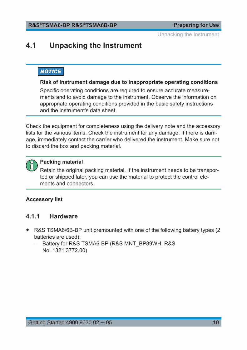
● R&S TSMA6/6B-BP unit premounted with one of the following battery types (2batteries are used):– Battery for R&S TSMA6-BP (R&S MNT_BP89WH, R&S
No. 1321.3772.00)
Unpacking the Instrument
Preparing for UseR&S®TSMA6-BP R&S®TSMA6B-BP
11Getting Started 4900.9030.02 ─ 05
Figure 4-1: R&S MNT-BP89WH
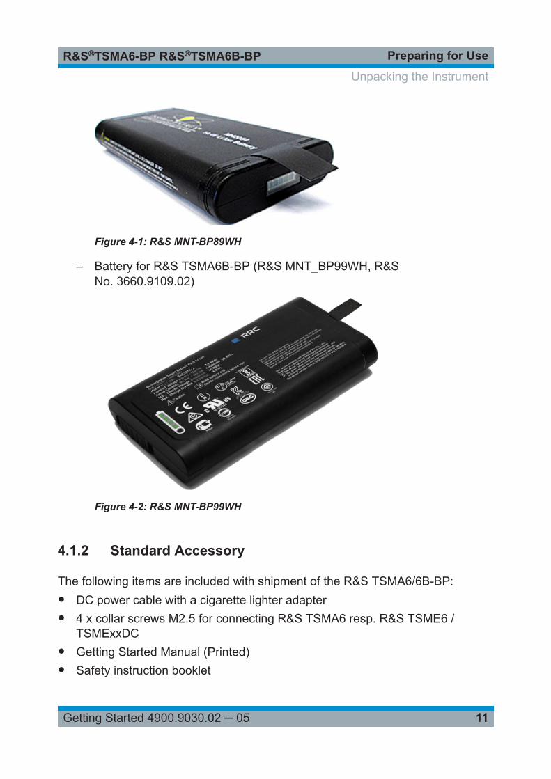
– Battery for R&S TSMA6B-BP (R&S MNT_BP99WH, R&SNo. 3660.9109.02)
Figure 4-2: R&S MNT-BP99WH
4.1.2 Standard Accessory
The following items are included with shipment of the R&S TSMA6/6B-BP:● DC power cable with a cigarette lighter adapter● 4 x collar screws M2.5 for connecting R&S TSMA6 resp. R&S TSME6 /
TSMExxDC● Getting Started Manual (Printed)● Safety instruction booklet
Unpacking the Instrument
Preparing for UseR&S®TSMA6-BP R&S®TSMA6B-BP
12Getting Started 4900.9030.02 ─ 05
● Safety instruction Li-Ion batteries
4.1.3 Optional Accessory
The following items are optional and must be ordered separately:
● R&S TSMA6-Z1 R&S No. 4901.0550.02AC power supply
● Only for model R&S TSMA6-BP: Additional Li-Ion battery pack R&SMNT_BP89WH, R&S No. 1321.3772.00 (see Figure 4-1)
● Only for model R&S TSMA6B-BP: Additional Li-Ion battery pack (R&SMNT_BP99WH, R&S No. 3660.9109.02 (see Figure 4-2)
● External charger for batteries– R&S TSMA-BC2,
Dual charger for R&S TSMA6/6B-BP batteries including country-specificpower cord
– R&S TSMA6-BC4, R&S No. 3630.7708.024-bay charger for R&S TSMA6/6B-BP batteries including country-specificpower cord
● Collar screws (as a spare part) (R&S No. 4900.0804.00)
To power TSMEx devices (scanner, downconverter), the following accessorycables are necessary.● R&S TSMA6-BPPT (single TSMEx power cable, R&S No. 4900.1730.02)● R&S TSMA6-BP2T (dual TSMEx power cable, R&S No. 4901.0566.02)
4.2 Connecting with External Power Supply andCharging the Batteries
Risk of instrument damage during operationRead and observe the "Safety Instruction for rechargeable Li-Ion batteries"delivered as a printed brochure with the instrument.
Connecting with External Power Supply and Charging the Batteries
Preparing for UseR&S®TSMA6-BP R&S®TSMA6B-BP
13Getting Started 4900.9030.02 ─ 05
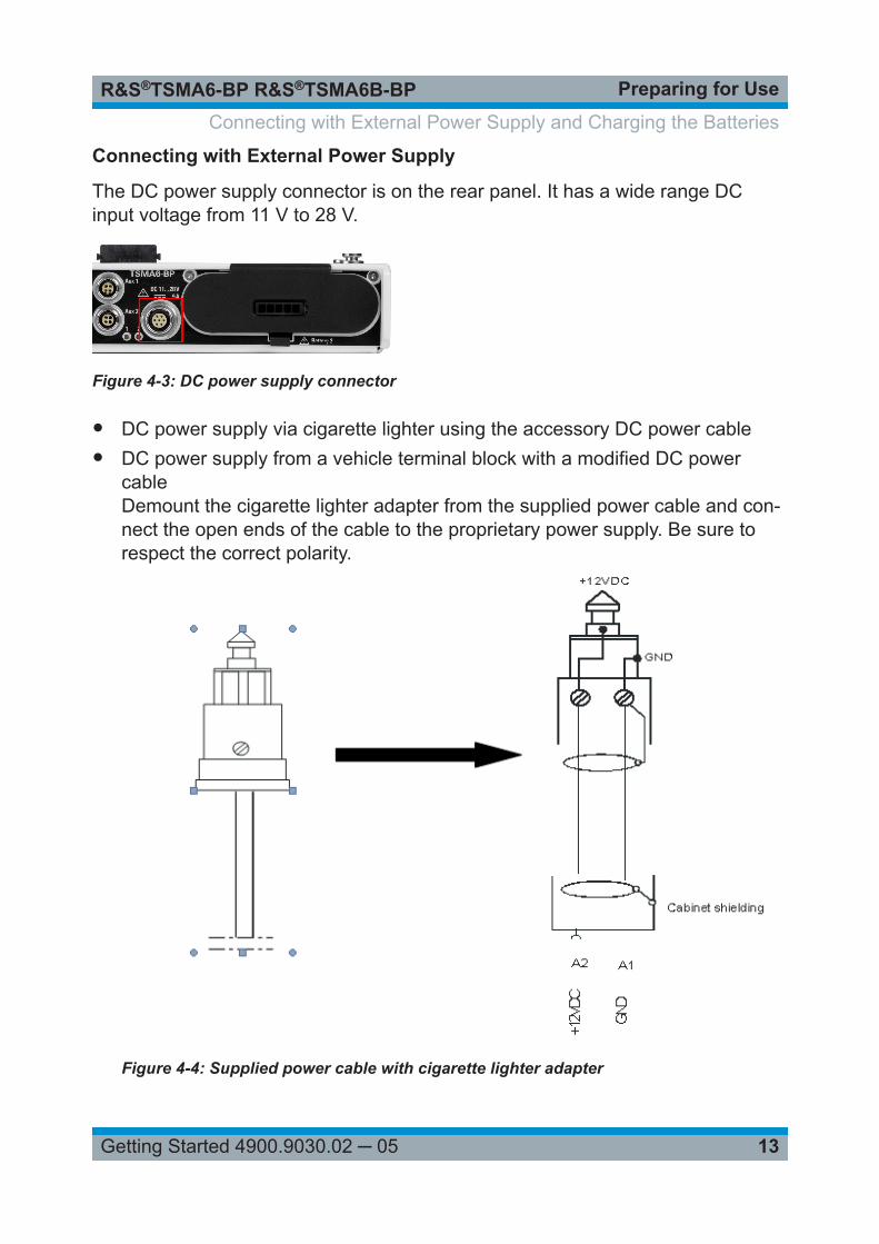
Connecting with External Power Supply
The DC power supply connector is on the rear panel. It has a wide range DCinput voltage from 11 V to 28 V.
Figure 4-3: DC power supply connector
● DC power supply via cigarette lighter using the accessory DC power cable● DC power supply from a vehicle terminal block with a modified DC power
cableDemount the cigarette lighter adapter from the supplied power cable and con-nect the open ends of the cable to the proprietary power supply. Be sure torespect the correct polarity.
Figure 4-4: Supplied power cable with cigarette lighter adapter
Connecting with External Power Supply and Charging the Batteries
Preparing for UseR&S®TSMA6-BP R&S®TSMA6B-BP
14Getting Started 4900.9030.02 ─ 05
● AC supply via R&S TSMA6-Z1 (optional accessory)
Charging the Batteries
The batteries are not charged on delivery. Before initial operation, the bat-teries must be fully charged without connected load (R&S TSMA6, R&STSME6 reps. R&S TSMExxDC).
For charging the batteries, the following possibilities are available:
● Charging starts automatically when DC power is connected.● Usage of external battery charger (optional accessory)
The external recharging of the batteries is only allowed via the followingcharger types:● R&S TSMA6-BC4, 4-bay charger● R&S TSMA-BC2, 2-bay charger
To check, if the batteries are fully charged, refer to Chapter 5.5, "Monitoring Bat-tery Charge State", on page 28.
4.3 Connecting the R&S TSMA6/6B-BP with R&STSMA6
Before initial operation, the batteries must be fully charged without an R&STSMA6 connected (see Chapter 4.2, "Connecting with External Power Sup-ply and Charging the Batteries", on page 12).
To connect the R&S TSMA6 with the R&S TSMA6/6B-BP, the following stepsmust be performed.
1. Remove the cover cap from the docking connector of the R&S TSMA6.
Connecting the R&S TSMA6/6B-BP with R&S TSMA6
Preparing for UseR&S®TSMA6-BP R&S®TSMA6B-BP
15Getting Started 4900.9030.02 ─ 05
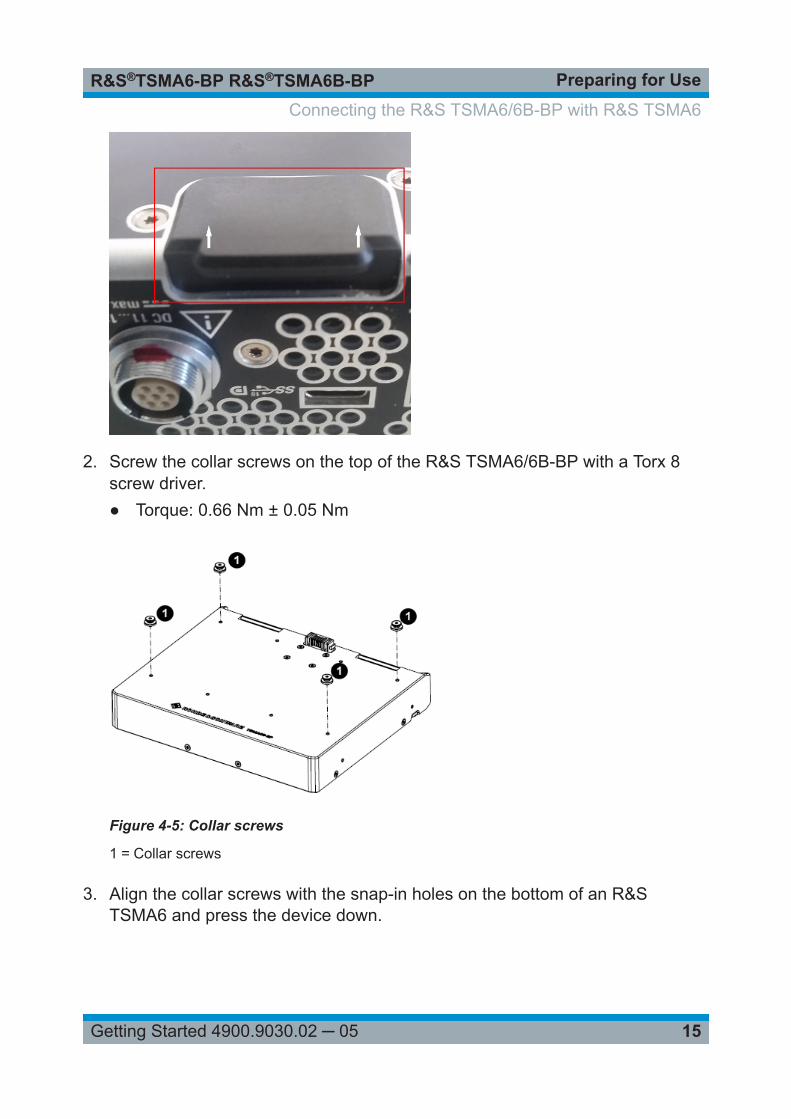
2. Screw the collar screws on the top of the R&S TSMA6/6B-BP with a Torx 8screw driver.● Torque: 0.66 Nm ± 0.05 Nm
Figure 4-5: Collar screws
1 = Collar screws
3. Align the collar screws with the snap-in holes on the bottom of an R&STSMA6 and press the device down.
Connecting the R&S TSMA6/6B-BP with R&S TSMA6
Preparing for UseR&S®TSMA6-BP R&S®TSMA6B-BP
16Getting Started 4900.9030.02 ─ 05
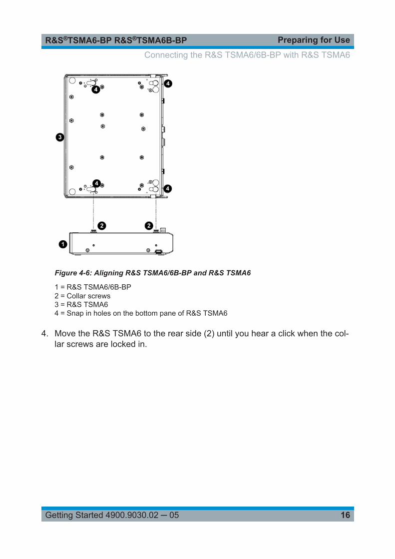
Figure 4-6: Aligning R&S TSMA6/6B-BP and R&S TSMA6
1 = R&S TSMA6/6B-BP2 = Collar screws3 = R&S TSMA64 = Snap in holes on the bottom pane of R&S TSMA6
4. Move the R&S TSMA6 to the rear side (2) until you hear a click when the col-lar screws are locked in.
Connecting the R&S TSMA6/6B-BP with R&S TSMA6
Preparing for UseR&S®TSMA6-BP R&S®TSMA6B-BP
17Getting Started 4900.9030.02 ─ 05
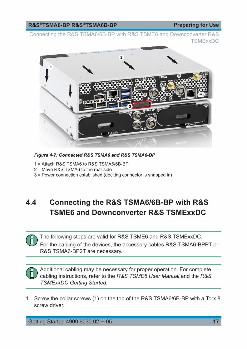
Figure 4-7: Connected R&S TSMA6 and R&S TSMA6-BP
1 = Attach R&S TSMA6 to R&S TSMA6/6B-BP2 = Move R&S TSMA6 to the rear side3 = Power connection established (docking connector is snapped in)
4.4 Connecting the R&S TSMA6/6B-BP with R&STSME6 and Downconverter R&S TSMExxDC
The following steps are valid for R&S TSME6 and R&S TSMExxDC.For the cabling of the devices, the accessory cables R&S TSMA6-BPPT orR&S TSMA6-BP2T are necessary.
Additional cabling may be necessary for proper operation. For completecabling instructions, refer to the R&S TSME6 User Manual and the R&STSMExxDC Getting Started.
1. Screw the collar screws (1) on the top of the R&S TSMA6/6B-BP with a Torx 8screw driver.
Connecting the R&S TSMA6/6B-BP with R&S TSME6 and Downconverter R&STSMExxDC
Preparing for UseR&S®TSMA6-BP R&S®TSMA6B-BP
18Getting Started 4900.9030.02 ─ 05
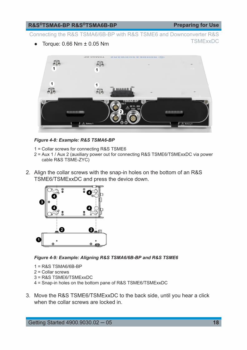
● Torque: 0.66 Nm ± 0.05 Nm
Figure 4-8: Example: R&S TSMA6-BP
1 = Collar screws for connecting R&S TSME62 = Aux 1 / Aux 2 (auxiliary power out for connecting R&S TSME6/TSMExxDC via power
cable R&S TSME-ZYC)
2. Align the collar screws with the snap-in holes on the bottom of an R&STSME6/TSMExxDC and press the device down.
Figure 4-9: Example: Aligning R&S TSMA6/6B-BP and R&S TSME6
1 = R&S TSMA6/6B-BP2 = Collar screws3 = R&S TSME6/TSMExxDC4 = Snap-in holes on the bottom pane of R&S TSME6/TSMExxDC
3. Move the R&S TSME6/TSMExxDC to the back side, until you hear a clickwhen the collar screws are locked in.
Connecting the R&S TSMA6/6B-BP with R&S TSME6 and Downconverter R&STSMExxDC
Preparing for UseR&S®TSMA6-BP R&S®TSMA6B-BP
19Getting Started 4900.9030.02 ─ 05
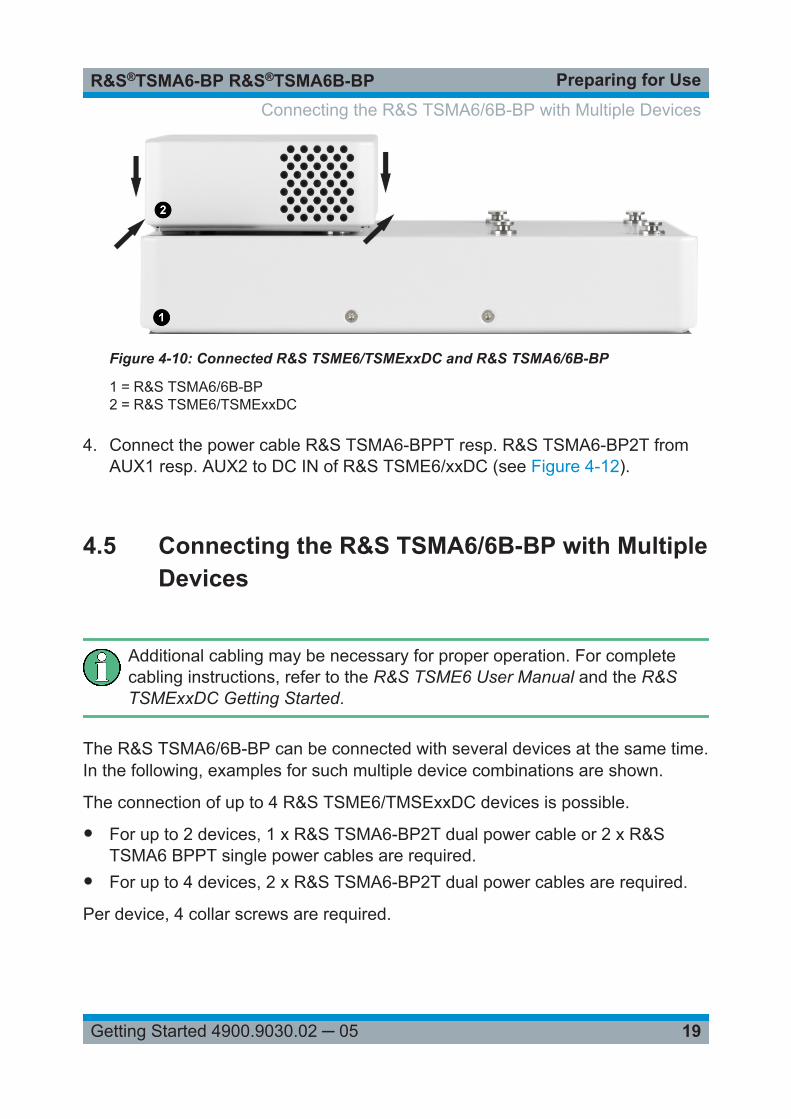
Figure 4-10: Connected R&S TSME6/TSMExxDC and R&S TSMA6/6B-BP
1 = R&S TSMA6/6B-BP2 = R&S TSME6/TSMExxDC
4. Connect the power cable R&S TSMA6-BPPT resp. R&S TSMA6-BP2T fromAUX1 resp. AUX2 to DC IN of R&S TSME6/xxDC (see Figure 4-12).
4.5 Connecting the R&S TSMA6/6B-BP with MultipleDevices
Additional cabling may be necessary for proper operation. For completecabling instructions, refer to the R&S TSME6 User Manual and the R&STSMExxDC Getting Started.
The R&S TSMA6/6B-BP can be connected with several devices at the same time.In the following, examples for such multiple device combinations are shown.
The connection of up to 4 R&S TSME6/TMSExxDC devices is possible.
● For up to 2 devices, 1 x R&S TSMA6-BP2T dual power cable or 2 x R&STSMA6 BPPT single power cables are required.
● For up to 4 devices, 2 x R&S TSMA6-BP2T dual power cables are required.
Per device, 4 collar screws are required.
Connecting the R&S TSMA6/6B-BP with Multiple Devices
Preparing for UseR&S®TSMA6-BP R&S®TSMA6B-BP
20Getting Started 4900.9030.02 ─ 05
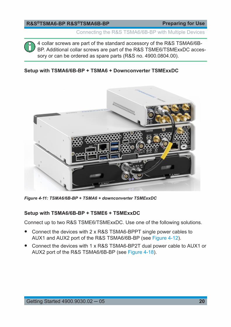
4 collar screws are part of the standard accessory of the R&S TSMA6/6B-BP. Additional collar screws are part of the R&S TSME6/TSMExxDC acces-sory or can be ordered as spare parts (R&S no. 4900.0804.00).
Setup with TSMA6/6B-BP + TSMA6 + Downconverter TSMExxDC
Figure 4-11: TSMA6/6B-BP + TSMA6 + downconverter TSMExxDC
Setup with TSMA6/6B-BP + TSME6 + TSMExxDC
Connect up to two R&S TSME6/TSMExxDC. Use one of the following solutions.
● Connect the devices with 2 x R&S TSMA6-BPPT single power cables toAUX1 and AUX2 port of the R&S TSMA6/6B-BP (see Figure 4-12).
● Connect the devices with 1 x R&S TSMA6-BP2T dual power cable to AUX1 orAUX2 port of the R&S TSMA6/6B-BP (see Figure 4-18).
Connecting the R&S TSMA6/6B-BP with Multiple Devices
Preparing for UseR&S®TSMA6-BP R&S®TSMA6B-BP
21Getting Started 4900.9030.02 ─ 05
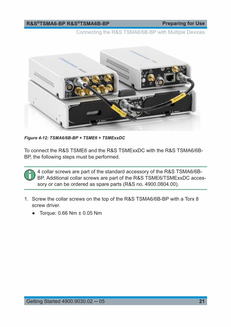
Figure 4-12: TSMA6/6B-BP + TSME6 + TSMExxDC
To connect the R&S TSME6 and the R&S TSMExxDC with the R&S TSMA6/6B-BP, the following steps must be performed.
4 collar screws are part of the standard accessory of the R&S TSMA6/6B-BP. Additional collar screws are part of the R&S TSME6/TSMExxDC acces-sory or can be ordered as spare parts (R&S no. 4900.0804.00).
1. Screw the collar screws on the top of the R&S TSMA6/6B-BP with a Torx 8screw driver.● Torque: 0.66 Nm ± 0.05 Nm
Connecting the R&S TSMA6/6B-BP with Multiple Devices
Preparing for UseR&S®TSMA6-BP R&S®TSMA6B-BP
22Getting Started 4900.9030.02 ─ 05
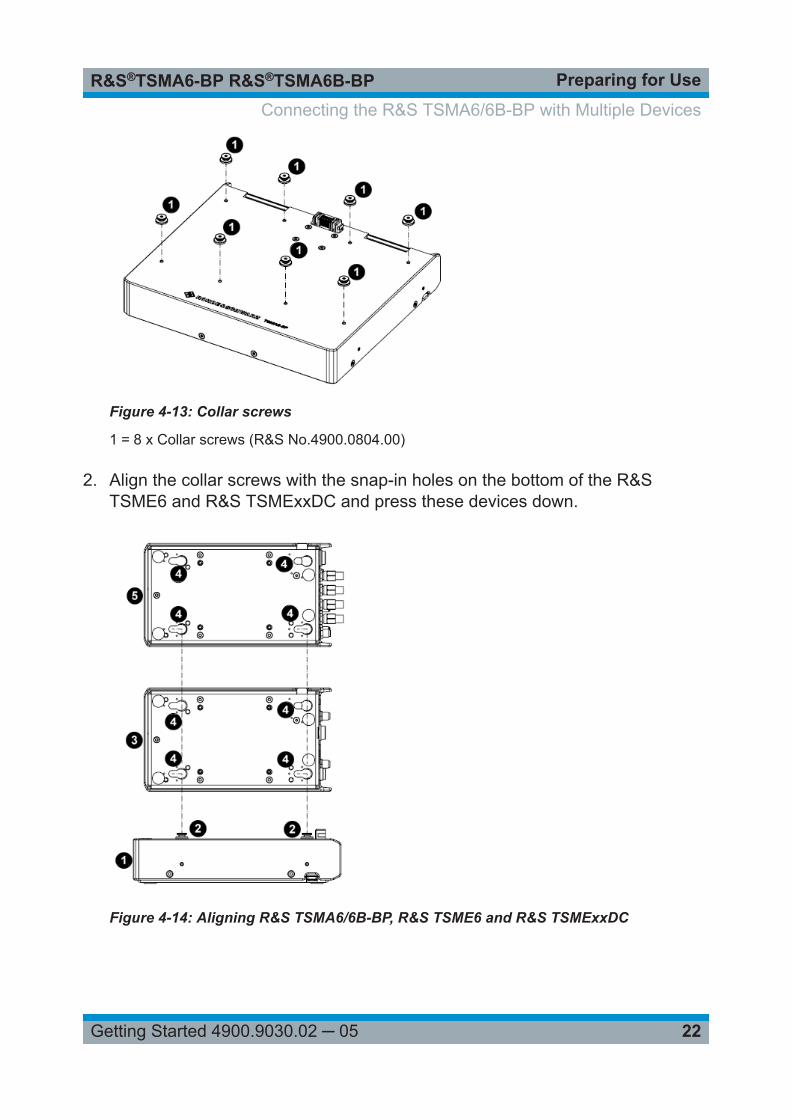
Figure 4-13: Collar screws
1 = 8 x Collar screws (R&S No.4900.0804.00)
2. Align the collar screws with the snap-in holes on the bottom of the R&STSME6 and R&S TSMExxDC and press these devices down.
Figure 4-14: Aligning R&S TSMA6/6B-BP, R&S TSME6 and R&S TSMExxDC
Connecting the R&S TSMA6/6B-BP with Multiple Devices
Preparing for UseR&S®TSMA6-BP R&S®TSMA6B-BP
23Getting Started 4900.9030.02 ─ 05
1 = R&S TSMA6/6B-BP2 = Collar screws3 = R&S TSME64 = Snap-in holes on the bottom pane of R&S TSME6 and R&S TSMExxDC5 = R&S TSMExxDC
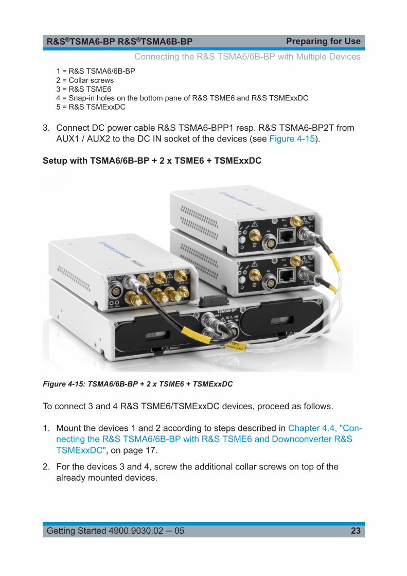
3. Connect DC power cable R&S TSMA6-BPP1 resp. R&S TSMA6-BP2T fromAUX1 / AUX2 to the DC IN socket of the devices (see Figure 4-15).
Setup with TSMA6/6B-BP + 2 x TSME6 + TSMExxDC
Figure 4-15: TSMA6/6B-BP + 2 x TSME6 + TSMExxDC
To connect 3 and 4 R&S TSME6/TSMExxDC devices, proceed as follows.
1. Mount the devices 1 and 2 according to steps described in Chapter 4.4, "Con-necting the R&S TSMA6/6B-BP with R&S TSME6 and Downconverter R&STSMExxDC", on page 17.
2. For the devices 3 and 4, screw the additional collar screws on top of thealready mounted devices.
Connecting the R&S TSMA6/6B-BP with Multiple Devices
Preparing for UseR&S®TSMA6-BP R&S®TSMA6B-BP
24Getting Started 4900.9030.02 ─ 05
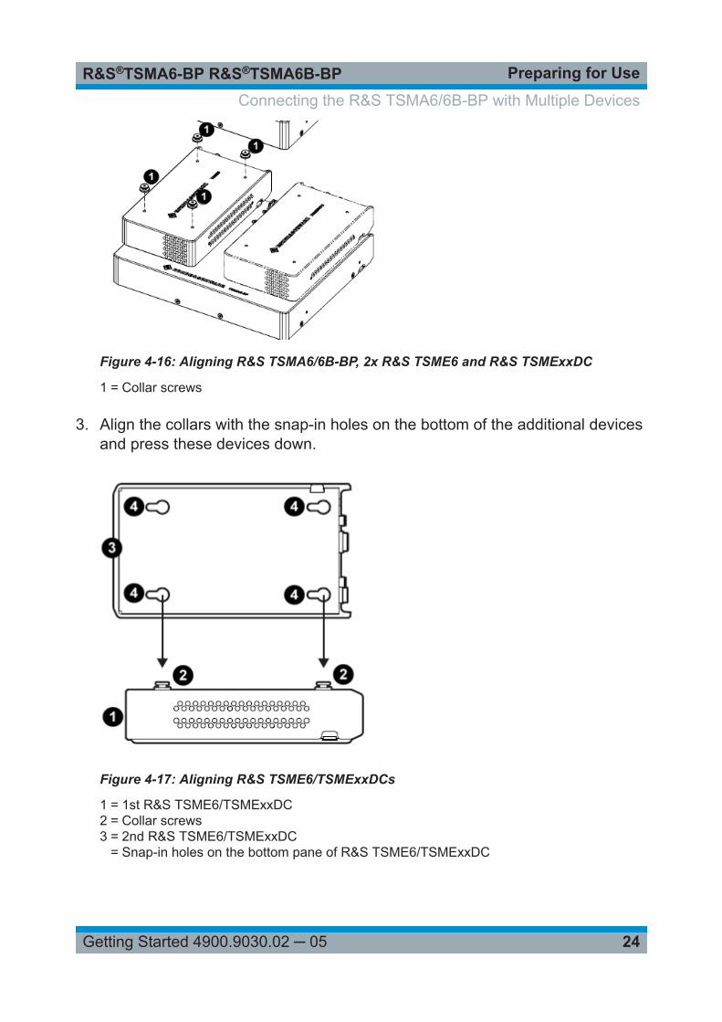
Figure 4-16: Aligning R&S TSMA6/6B-BP, 2x R&S TSME6 and R&S TSMExxDC
1 = Collar screws
3. Align the collars with the snap-in holes on the bottom of the additional devicesand press these devices down.
Figure 4-17: Aligning R&S TSME6/TSMExxDCs
1 = 1st R&S TSME6/TSMExxDC2 = Collar screws3 = 2nd R&S TSME6/TSMExxDC
= Snap-in holes on the bottom pane of R&S TSME6/TSMExxDC
Connecting the R&S TSMA6/6B-BP with Multiple Devices
Preparing for UseR&S®TSMA6-BP R&S®TSMA6B-BP
25Getting Started 4900.9030.02 ─ 05
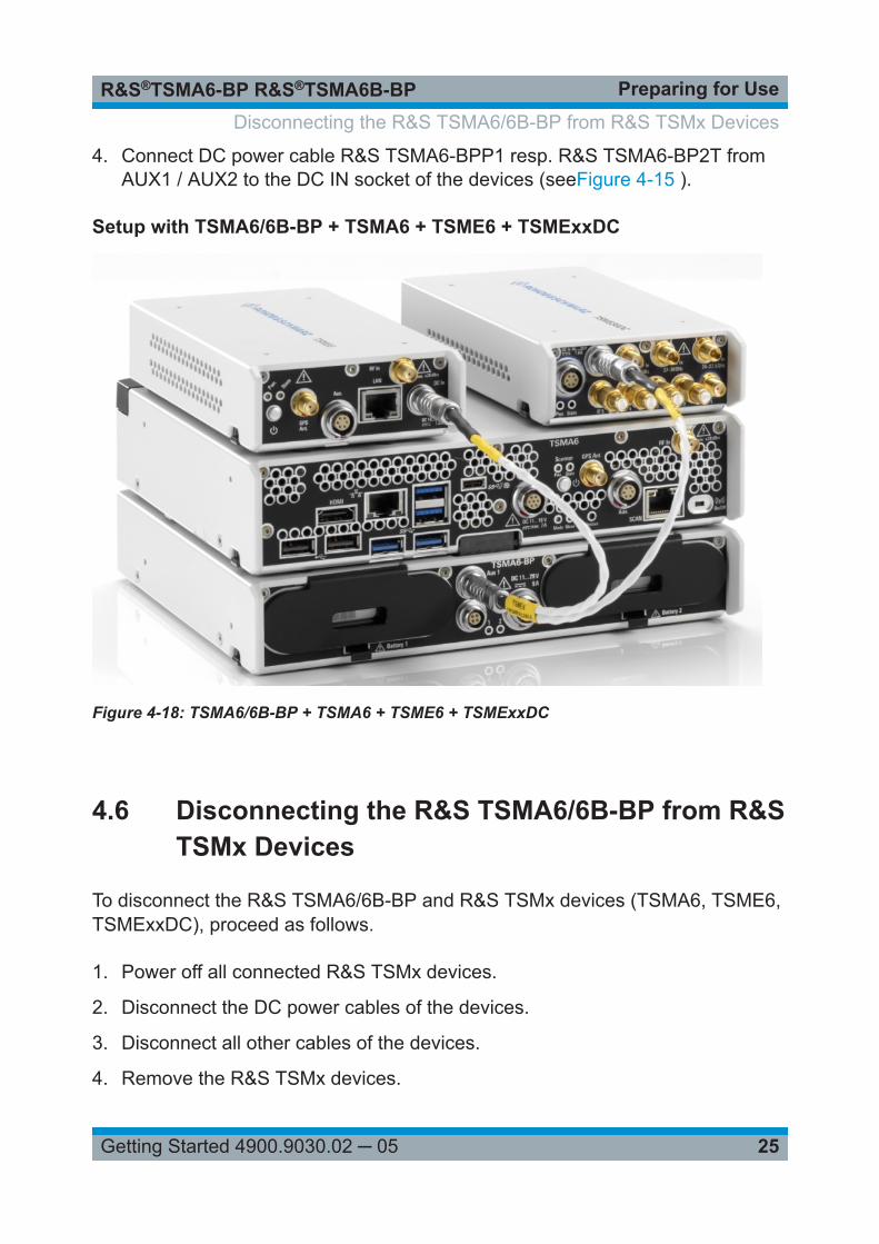
4. Connect DC power cable R&S TSMA6-BPP1 resp. R&S TSMA6-BP2T fromAUX1 / AUX2 to the DC IN socket of the devices (seeFigure 4-15 ).
Setup with TSMA6/6B-BP + TSMA6 + TSME6 + TSMExxDC
Figure 4-18: TSMA6/6B-BP + TSMA6 + TSME6 + TSMExxDC
4.6 Disconnecting the R&S TSMA6/6B-BP from R&STSMx Devices
To disconnect the R&S TSMA6/6B-BP and R&S TSMx devices (TSMA6, TSME6,TSMExxDC), proceed as follows.
1. Power off all connected R&S TSMx devices.
2. Disconnect the DC power cables of the devices.
3. Disconnect all other cables of the devices.
4. Remove the R&S TSMx devices.
Disconnecting the R&S TSMA6/6B-BP from R&S TSMx Devices
Preparing for UseR&S®TSMA6-BP R&S®TSMA6B-BP
26Getting Started 4900.9030.02 ─ 05
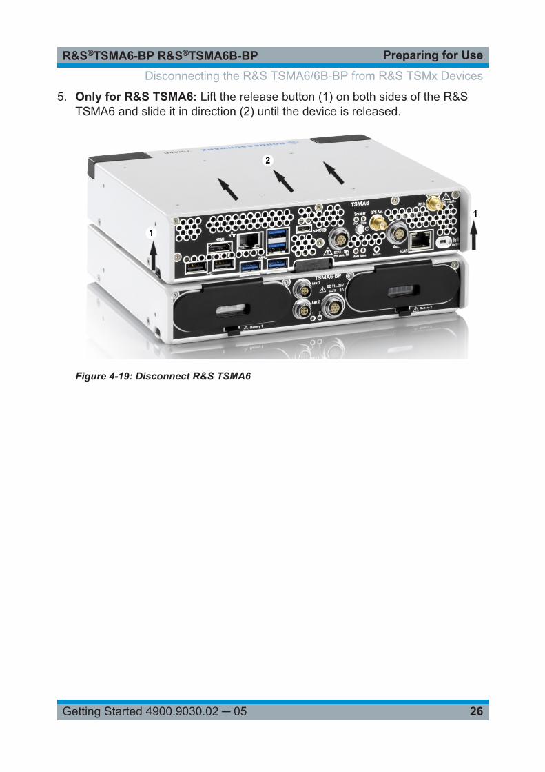
5. Only for R&S TSMA6: Lift the release button (1) on both sides of the R&STSMA6 and slide it in direction (2) until the device is released.
Figure 4-19: Disconnect R&S TSMA6
Disconnecting the R&S TSMA6/6B-BP from R&S TSMx Devices
OperationR&S®TSMA6-BP R&S®TSMA6B-BP
27Getting Started 4900.9030.02 ─ 05
5 OperationFor portable operation powered from the batteries, it is recommended touse the R&S TSMA6/6B-BP always with 2 batteries in the bay. The batter-ies should have a comparable charging state as they are discharged simul-taneously.
● Operation Modes.............................................................................................27● Power On/Off...................................................................................................27● Battery Charging............................................................................................. 28● Power Path Switching..................................................................................... 28● Monitoring Battery Charge State.....................................................................28● Battery Exchange - Hot Swapping.................................................................. 32
5.1 Operation Modes
● Standalone modeIn the standalone mode, the battery pack unit is used without an R&STSMA6.The charging state indicator LEDs are controlled autonomously.
● Host-Controlled modeThe R&S TSMA6 controls the charge indicator LEDs via the SMBus interface.
5.2 Power On/Off
5.2.1 Auto Power On
In standalone mode, the output voltage at the docking connector TSMA6 andAUX1 / AUX2 is automatically switched on under the following conditions:
● sufficiently charged batteries and / or● external DC power supply connected
Power On/Off
OperationR&S®TSMA6-BP R&S®TSMA6B-BP
28Getting Started 4900.9030.02 ─ 05
5.2.2 Standby
In host-controlled mode (R&S TSMA6 connected), the battery pack can beswitched to standby mode by switching off the R&S TSMA6. In this case, the out-puts AUX1 / AUX2 are also switched off.
If there is a shutdown by the R&S TSMA6, the voltage at AUX1 / AUX 2 can bereactivated by switching on the R&S TSMA6.
A R&S TSMA6/6B-BP in standby mode can be switched on again without R&STSMA6 only by shortly removing the DC supply and both batteries.
5.3 Battery Charging
During operation with external power supply, the batteries are automaticallycharged.
Depending on the number of connected devices and the measuring mode, charg-ing may take longer because only part of the power consumption can be used forbattery charging.
5.4 Power Path Switching
Switching between battery and external power supply is done automatically.When an appropriate power supply is connected to the DC IN socket, the connec-ted devices are supplied from the external power supply and the batteries arecharged.
If the external input power is interrupted or cracking, connected devices are pow-ered seamless from the batteries.
5.5 Monitoring Battery Charge State
The battery charging state can be monitored via the following possibilities:
Monitoring Battery Charge State
OperationR&S®TSMA6-BP R&S®TSMA6B-BP
29Getting Started 4900.9030.02 ─ 05
● Battery Charge Display................................................................................... 29● Rear Panel LEDs............................................................................................ 30● R&S TSMA6 web-GUI / Tray Icon (Only Host-Controlled Mode).................... 32
5.5.1 Battery Charge Display
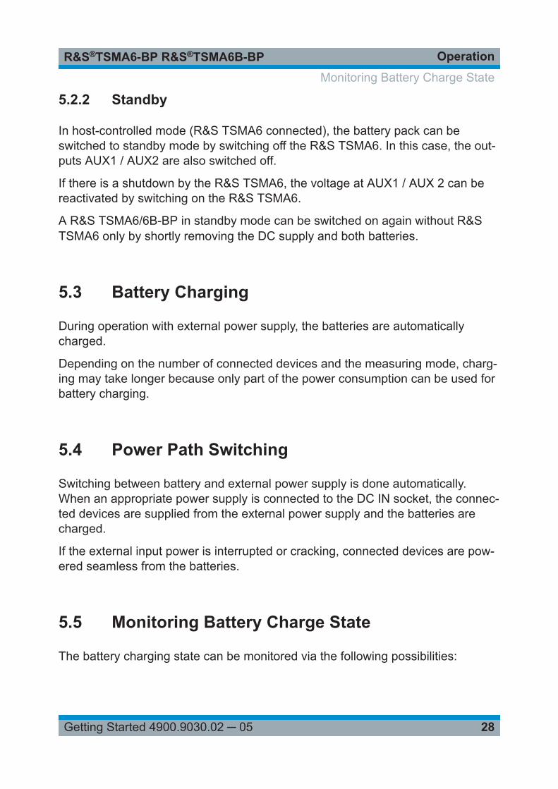
Figure 5-1: R&S TSMA6-BP with R&S BP89WH batteries (R&S No.1321.3772.00)
1 = Charging state display (only for R&S TSMA6-BP and R&S BP89WH batteries)
● R&S TSMA6-BP / MNT-BP89WH: The discharge status is visible via the bat-tery internal display without removing the batteries (see Figure 5-1).When the batteries are being charged the upper segement of the LCD displayis blinking.
● R&S TSMA6B-BP / MNT-BP99WH: During an active measurement when noDC IN power is connected, proceed as follows.Remove the batteries alternately, check the discharge state from the internaldisplay and insert it again. Ensure that always one battery remains in the bayto ensure uninterrupted output power.When external DC power is connected or when the batteries are beingcharged without connected devices, both batteries can be removed andchecked.
Monitoring Battery Charge State
OperationR&S®TSMA6-BP R&S®TSMA6B-BP
30Getting Started 4900.9030.02 ─ 05
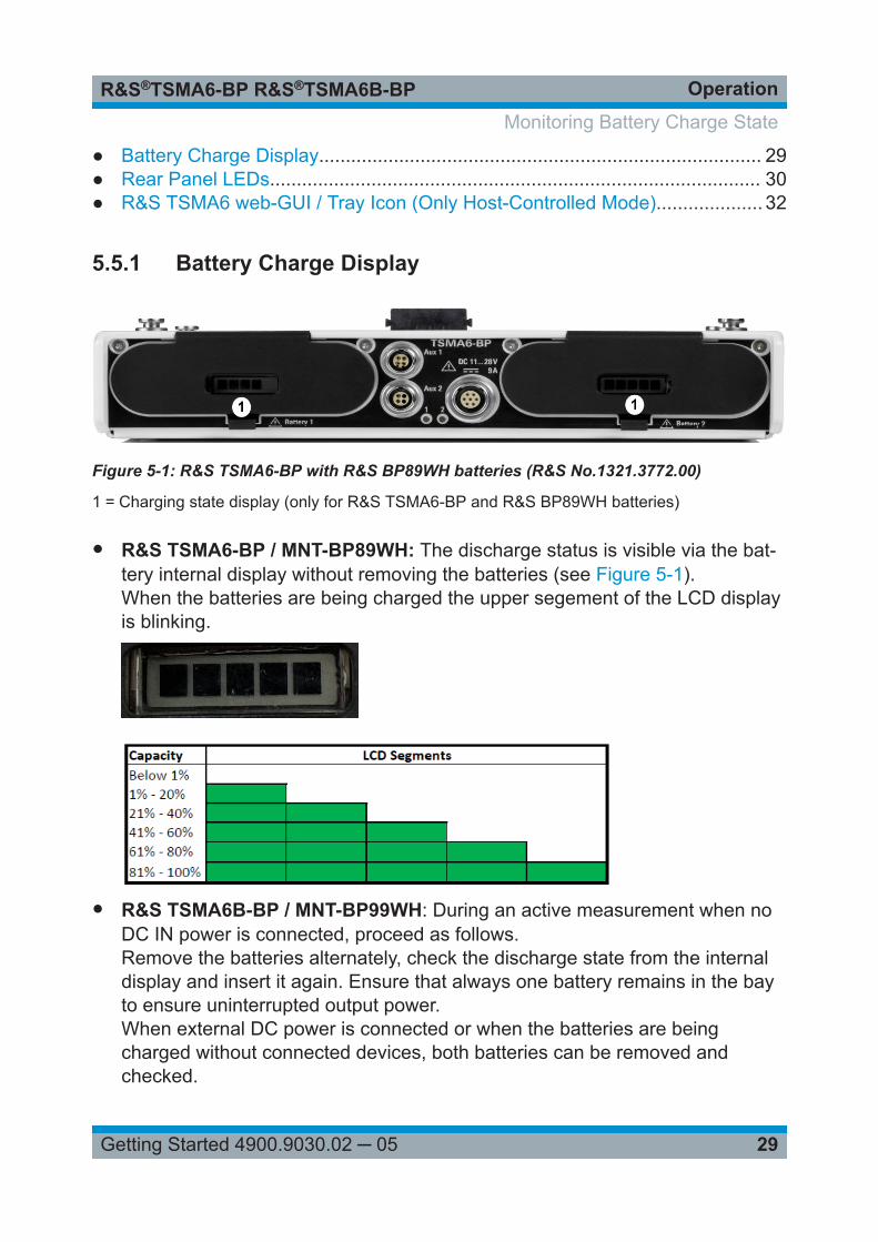
To display the charging state, press the button below the LCD segments for afew seconds.When the batteries are being charged the upper segement of the LCD displayis blinking.
5.5.2 Rear Panel LEDs
Figure 5-2: R&S TSMA6/6B-BP - status LEDs
1 = Status LED for battery 12 = Status LED for battery 2
Monitoring Battery Charge State
OperationR&S®TSMA6-BP R&S®TSMA6B-BP
31Getting Started 4900.9030.02 ─ 05
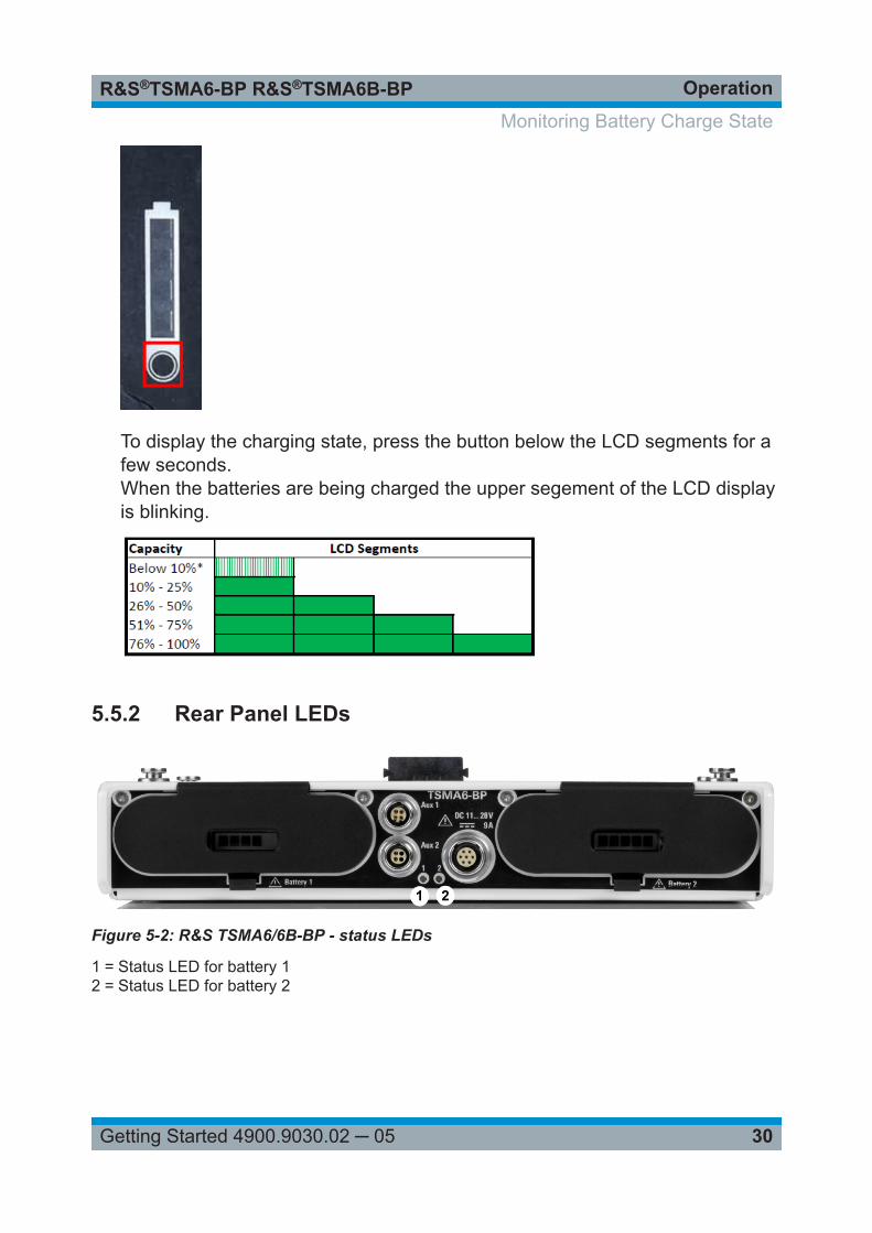
Table 5-1: LED states and their meaning (LED 1 and LED 2) in standalone mode (no R&STSMA6 connected resp. R&S TSMA6 switched off)
Color LED state Comment
--- OFF Battery 1/2 not present orexternal DC power not availa-ble*
green BLINKING (2 Hz) Battery fully charged (100 %)
green ON Battery charging in progress /external DC power connected
*In standalone mode the battery charge is only displayed when an external DCpower supply is connected. The battery charge in mobile operation can only beread directly from the battery (see Chapter 5.5.1, "Battery Charge Display",on page 29).
Table 5-2: LED states and their meaning (LED 1 and LED 2) in host-controlled mode (R&STSMA6 connected and switched on)
Mode Color State Comment
No battery --- OFF Battery 1/2 notpresent
Battery pow-ered /Fullcharge
blue ON Charging state >21%
Battery pow-ered / Lowcharge
blue BLINKING (0.5 Hz) 20 % > Chargingstate > 10%
Battery pow-ered / Criticalcharge
blue BLINKING (2 Hz) Charging state <10%
ExternalPower /Charging
green ON Battery 1/2 charg-ing in progress
ExternalPower /Charging fin-ished
green BLINKING (2 Hz) Battery 1/2 charg-ing completed
Misc cyan BLINKING (5 Hz) any other repor-ted state, e.g. bat-tery error
Monitoring Battery Charge State
OperationR&S®TSMA6-BP R&S®TSMA6B-BP
32Getting Started 4900.9030.02 ─ 05
5.5.3 R&S TSMA6 web-GUI / Tray Icon (Only Host-ControlledMode)
In host-controlled mode, the battery charging state can be monitored from theweb-GUI or from the tray icon in the Windows OS.
For details, refer to "R&S TSMA6 Autonomous Mobile Network Scanner - UserManual" (R&S No. 4900.8057.02).
5.6 Battery Exchange - Hot Swapping
When the battey charge reaches a low level, the batteries need to be replaced.This can be done through hot swapping without interrupting the measurement onthe connected devices.
The batteries are both discharged evenly. Therefore it is recommended toreplace always both batteries.In case of a hot-swap, do not exchange the batteries simultaneously butone after the other.
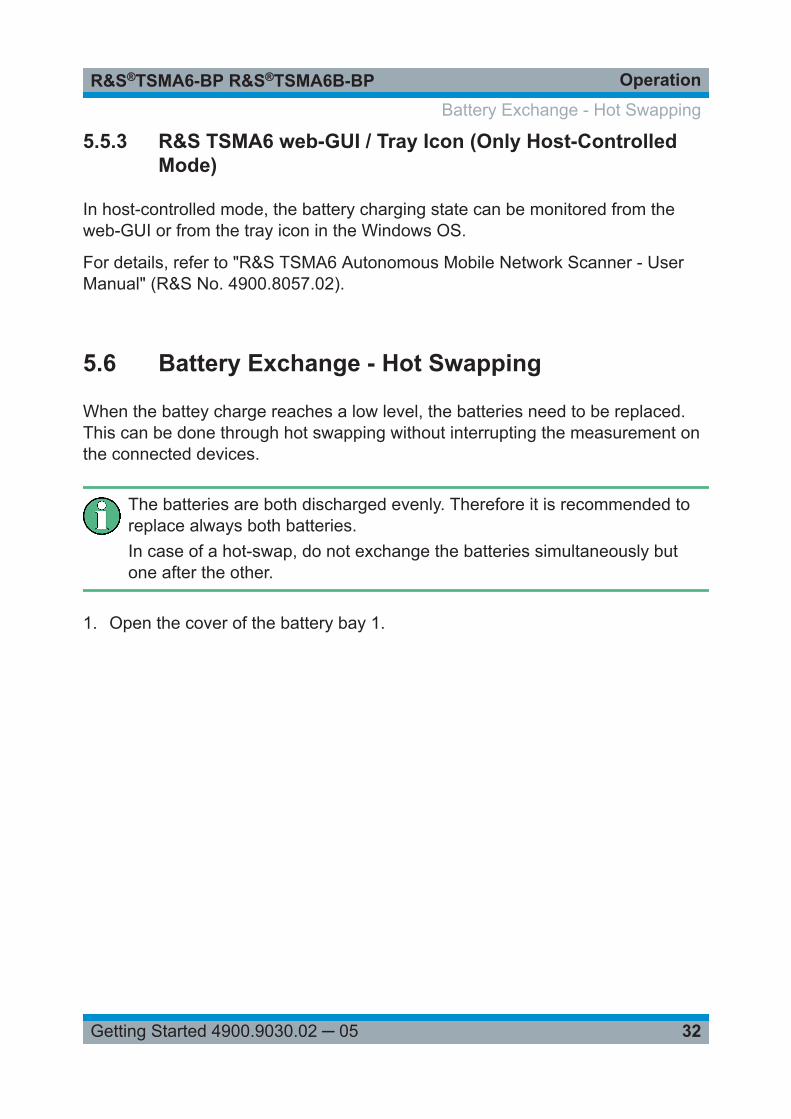
1. Open the cover of the battery bay 1.
Battery Exchange - Hot Swapping
OperationR&S®TSMA6-BP R&S®TSMA6B-BP
33Getting Started 4900.9030.02 ─ 05
Figure 5-3: Open battery cover
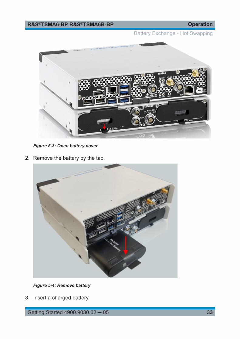
2. Remove the battery by the tab.
Figure 5-4: Remove battery
3. Insert a charged battery.
Battery Exchange - Hot Swapping
OperationR&S®TSMA6-BP R&S®TSMA6B-BP
34Getting Started 4900.9030.02 ─ 05
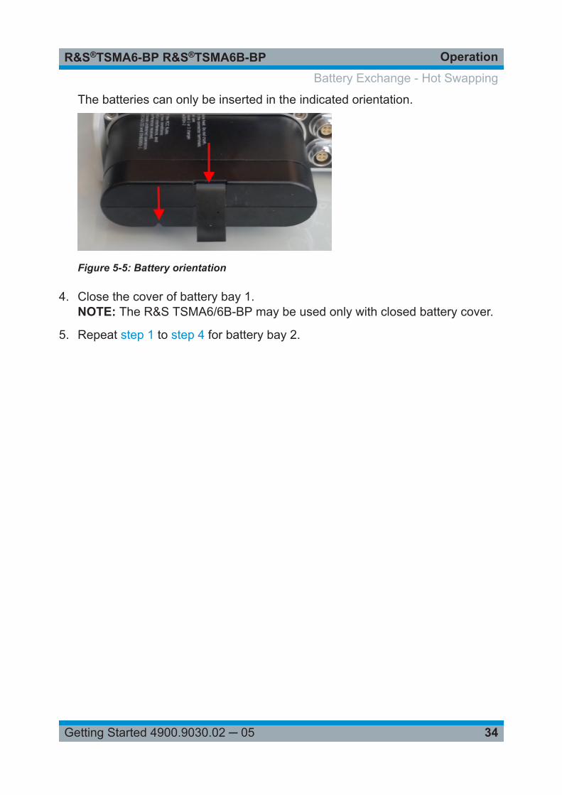
The batteries can only be inserted in the indicated orientation.
Figure 5-5: Battery orientation
4. Close the cover of battery bay 1.NOTE: The R&S TSMA6/6B-BP may be used only with closed battery cover.
5. Repeat step 1 to step 4 for battery bay 2.
Battery Exchange - Hot Swapping
Contacting Customer SupportR&S®TSMA6-BP R&S®TSMA6B-BP
35Getting Started 4900.9030.02 ─ 05
6 Contacting Customer SupportTechnical support – where and when you need it
For quick, expert help with any Rohde & Schwarz product, contact our customersupport center. A team of highly qualified engineers provides support and workswith you to find a solution to your query on any aspect of the operation, program-ming or applications of Rohde & Schwarz products.
Contact information
Contact our customer support center at www.rohde-schwarz.com/support, or fol-low this QR code:
Figure 6-1: QR code to the Rohde & Schwarz support page
IndexR&S®TSMA6-BP R&S®TSMA6B-BP
36Getting Started 4900.9030.02 ─ 05
Index
B
Brochures .................................................. 6
C
Customer support .................................... 35
D
Data sheets ............................................... 6
G
Getting started ........................................... 6
H
Hot swap ................................................. 32
L
LED display ............................................. 28LED states
host-controlled mode .......................... 31standalone mode ................................ 31
O
Operation modeStandalone ..........................................27TSMA6-controlled ............................... 27
S
Safety instructions ..................................... 6


![]B8}Z˝s˝$Bt BP Gs——st˝k i‡R‡—%‡R b$˝Y p‡t‡—sj …vkulkarn/papers/wargensp.pdfqY‡R‡PZtIRs—‡R‡˝sR$I‡s˝˝Y‡A‡˙$tt$t˙BP˝Y‡Rsj‡R}‡—$BIPB—˝Y‡bs——st˝k{BR˝RBP](https://img.pdfslide.net/doc/110x75/5aaa7b827f8b9a9a188e495c/b8zsbt-bp-gsstk-irr-by-ptsj-vkulkarnpapers.jpg)
![85W and 90W Photovoltaic modules BP 485J - BP 490J485J+-+BP+490J.pdfbp sola r 1234567 X XXXX X Without Screw Heads 1204 [47.4] Certification Certified according to the extended version](https://img.pdfslide.net/doc/110x75/5af510c97f8b9ae9488cf2aa/85w-and-90w-photovoltaic-modules-bp-485j-bp-490j-485j-bp490jpdfbp-sola-r-1234567.jpg)