Embed Size (px)
Citation preview
RS232A synchronous communicationsadapter supporting speedsup to 64,000 bps.
Documentation Edition 5Adapter Revision 1
EditorsCraig R. LeeKathy Sutton
HardwareAl Hodges
SoftwareKen Clark
Copyright © 1988-1995 by Barr Systems, Inc.All Rights Reserved.
Barr Systems, Inc.P.O. Box 147015Gainesville, FL 32614-7015
Phone: 800-BARR-SYS800-227-7797352-491-3100
Fax: 352-491-3141
Internet: [email protected] site: www.BarrSys.comFTP site: ftp.BarrSys.com
® and BARR/RJE are trademarks of Barr Systems, Inc. IBM®, IBMPersonal Computer , and Personal Computer AT®, are trademarks ofInternational Business Machines Corp.
August 1995

. Preface
Welcome to a product that offers synchronous communicationsat speeds of 64 Kbps using an RS232 communications lineinterface. Follow the step-by-step instructions in this manual toinstall the RS232 adapter.
Chapter 1 describes the package contents and systemrequirements. Review this chapter to be sure you haveeverything needed before beginning installation.
Chapter 2 provides detailed instructions for installing theRS232 adapter and SCC1 cable. The adapter is installed ina PC with an ISA or EISA bus.
Chapter 3 tells you how to enter adapter information in theBarr software.
Chapter 4 explains how to run the Barr loopback test toverify that the adapter is functioning properly.
Barr Technical Support
Contact Barr Technical Support if you have any questions orproblems. When calling Technical Support, please have youradapter serial number and the software version number onhand. When contacting Technical Support via Fax or E-mail,please include the serial number in your correspondence.
You can obtain the adapter serial number from the:
Adapter box
Sticker on the adapter edge that is visible from the rear ofthe PC
Handwritten label on the back of the adapter
RS232 iii

Notes:
iv Preface
Contents
Preface . . . . . . . . . . . . . . . . . . . . . . . . . . . . . . . . . . . . . . iii
Chapter 1 Introduction . . . . . . . . . . . . . . . . . . . . . . . . . 1
1.1 Features . . . . . . . . . . . . . . . . . . . . . . . . . . . . . . . . . 2Speeds up to 64 Kbps . . . . . . . . . . . . . . . . . . . . . . 2Full-Duplex Communications . . . . . . . . . . . . . . . 2Direct Memory Access . . . . . . . . . . . . . . . . . . . . . 2Modem or SME Connection. . . . . . . . . . . . . . . . . 3Loopback Diagnostics . . . . . . . . . . . . . . . . . . . . . 3
1.2 PC Requirements . . . . . . . . . . . . . . . . . . . . . . . . . 3
1.3 Package Contents . . . . . . . . . . . . . . . . . . . . . . . . . 4
Chapter 2 Install the RS232 Adapter. . . . . . . . . . . . . . 5
2.1 Adapter Settings . . . . . . . . . . . . . . . . . . . . . . . . . . 5Address Jumper. . . . . . . . . . . . . . . . . . . . . . . . . . . 6
2.2 Connection to a Host . . . . . . . . . . . . . . . . . . . . . . 6
Chapter 3 Adjust Software Settings . . . . . . . . . . . . . . 7
3.1 Interrupt Request, Address, and Loopback Test Screen. . . . . . . . . . . . . . . . . . . . 8
3.2 Additional Adapter Information . . . . . . . . . . . . 10
Chapter 4 Perform the Loopback Test . . . . . . . . . . . 11
4.1 Loopback Test Steps . . . . . . . . . . . . . . . . . . . . . 12
4.2 Loopback Test Results. . . . . . . . . . . . . . . . . . . . 15
RS232 v
Appendix A Barr SCC1 Cable Specifications . . . . . . . 17
A.1 Barr SCC1 Modem Cable . . . . . . . . . . . . . . . . . 17
A.2 Synchronous Modem Eliminator Cable . . . . . . 18Barr SME Connector . . . . . . . . . . . . . . . . . . . . . 18Connect the PC to the Front-End Processor. . . . 20
Appendix B Modems . . . . . . . . . . . . . . . . . . . . . . . . . . . 23
Federal Communications Commission (FCC) Statement. . . . . . . . . . . . . . . . . . . . . . . . . . . . . . . . . . . . 25
Warranty Information. . . . . . . . . . . . . . . . . . . . . . . . . . . . 27
vi Contents
Chapter
1 Introduction
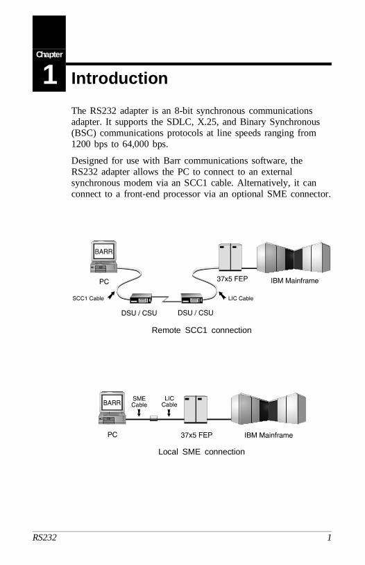
The RS232 adapter is an 8-bit synchronous communicationsadapter. It supports the SDLC, X.25, and Binary Synchronous(BSC) communications protocols at line speeds ranging from1200 bps to 64,000 bps.
Designed for use with Barr communications software, theRS232 adapter allows the PC to connect to an externalsynchronous modem via an SCC1 cable. Alternatively, it canconnect to a front-end processor via an optional SME connector.
Remote SCC1 connection
Local SME connection
RS232 1
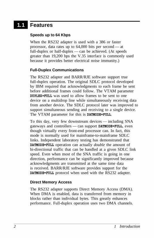
1.1 Features
Speeds up to 64 Kbps
When the RS232 adapter is used with a 386 or fasterprocessor, data rates up to 64,000 bits per second — atfull-duplex or half-duplex — can be achieved. (At speedsgreater than 19,200 bps the V.35 interface is commonly usedbecause it provides better electrical noise immunity.)
Full-Duplex Communications
The RS232 adapter and BARR/RJE software support truefull-duplex operation. The original SDLC protocol developedby IBM required that acknowledgments to each frame be sentbefore additional frames could follow. The VTAM parameterDUPLEX=FULL was used to allow frames to be sent to onedevice on a multidrop line while simultaneously receiving datafrom another device. The SDLC protocol later was improved tosupport simultaneous sending and receiving to a single device.The VTAM parameter for this is DATMODE=FULL.
To this day, very few downstream devices — including SNAgateways and controllers — can support DATMODE=FULL, eventhough virtually every front-end processor can. In fact, thismode is normally used for mainframe-to-mainframe SDLClinks. Independent laboratory testing has demonstrated thatDATMODE=FULL operation can actually double the amount ofbi-directional traffic that can be handled at a given SDLC linkspeed. Even when most of the SNA traffic is going in onedirection, performance can be significantly improved becauseacknowledgments are transmitted at the same time datais received. BARR/RJE software provides support for theDATMODE=FULL protocol when used with the RS232 adapter.
Direct Memory Access
The RS232 adapter supports Direct Memory Access (DMA).When DMA is enabled, data is transferred from memory inblocks rather than individual bytes. This greatly enhancesperformance. Full-duplex operation uses two DMA channels.
2 1 Introduction
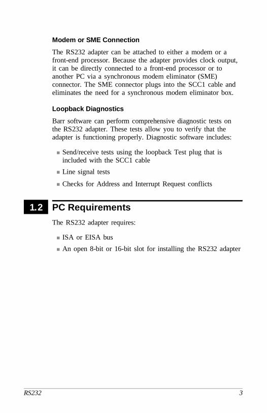
Modem or SME Connection
The RS232 adapter can be attached to either a modem or afront-end processor. Because the adapter provides clock output,it can be directly connected to a front-end processor or toanother PC via a synchronous modem eliminator (SME)connector. The SME connector plugs into the SCC1 cable andeliminates the need for a synchronous modem eliminator box.
Loopback Diagnostics
Barr software can perform comprehensive diagnostic tests onthe RS232 adapter. These tests allow you to verify that theadapter is functioning properly. Diagnostic software includes:
Send/receive tests using the loopback Test plug that isincluded with the SCC1 cable
Line signal tests
Checks for Address and Interrupt Request conflicts
1.2 PC Requirements
The RS232 adapter requires:
ISA or EISA bus
An open 8-bit or 16-bit slot for installing the RS232 adapter
RS232 3

1.3 Package Contents
The RS232 adapter box includes:
RS232 synchronous communications adapter
2.5-meter (8-foot) Barr SCC1 cable with Test plug
4 1 Introduction
Chapter
2 Install the RS232 Adapter
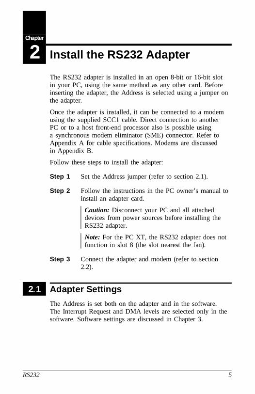
The RS232 adapter is installed in an open 8-bit or 16-bit slotin your PC, using the same method as any other card. Beforeinserting the adapter, the Address is selected using a jumper onthe adapter.
Once the adapter is installed, it can be connected to a modemusing the supplied SCC1 cable. Direct connection to anotherPC or to a host front-end processor also is possible usinga synchronous modem eliminator (SME) connector. Refer toAppendix A for cable specifications. Modems are discussedin Appendix B.
Follow these steps to install the adapter:
Step 1 Set the Address jumper (refer to section 2.1).
Step 2 Follow the instructions in the PC owner’s manual toinstall an adapter card.
Caution: Disconnect your PC and all attacheddevices from power sources before installing theRS232 adapter.
Note: For the PC XT, the RS232 adapter does notfunction in slot 8 (the slot nearest the fan).
Step 3 Connect the adapter and modem (refer to section2.2).
2.1 Adapter Settings
The Address is set both on the adapter and in the software.The Interrupt Request and DMA levels are selected only in thesoftware. Software settings are discussed in Chapter 3.
RS232 5

Address Jumper
Before installing the adapter, identify which addresses arein use by adapters already installed in your PC. If you do notknow which device addresses are available, do not change thesetting of the RS232 adapter. You will find out with certaintywhether there is a conflict after initially installing the adapterand booting up your PC.
The Address on the RS232 adapter is selected using a jumperon the top edge of the adapter. The adapter is preset tohexadecimal Address 280 (includes 281-287). Other Addresschoices are 290, 2A0, and 2B0.
Note: Change this setting only if you verify a conflict withother equipment in the PC.
The RS232 adapter only decodes the low 10 address lines.This means that the RS232 will conflict with any other adapterwhose low 10 address lines match the RS232 address. The low10 address lines specify hexadecimal addresses from 0000 to03FF.
If you have verified an Address conflict with another adapter,move the jumper to one of the other settings. The settings areclearly marked on the adapter.
After you have completed the RS232 adapter installation, youneed to check the Address setting in the Barr software to makesure it matches the adapter setting.
2.2 Connection to a Host
Once the adapter is installed in the PC, it can be connected toa modem using the SCC1 cable. Direct connection to anotherPC or to a host front-end processor also is possible using asynchronous modem eliminator (SME) connector.
Refer to Appendix A for cable specifications and SMEinstallation instructions. Modems are discussed in Appendix B.
6 2 Installation of RS232 Adapter
Chapter
3 Adjust Software Settings
The Installation chapters of your Barr software manualcompletely describe software installation. This chapter coversthe additional RS232 adapter parameters you need to specify.
In the Barr software, you need to enter the Interrupt Requestlevel (IRQ), Address, and DMA settings for the adapter.
To run the Barr software, at the DOS prompt enter the Barrsoftware startup command followed by the letter i. Forexample, for BARR/RJE enter:
BARRSNAR i
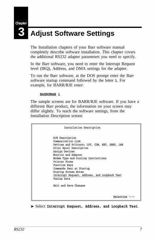
The sample screens are for BARR/RJE software. If you have adifferent Barr product, the information on your screen maydiffer slightly. To reach the software settings, from theInstallation Description screen:
Installation Description
RJE Description Communication Link Devices and Printers: LPT, COM, NET, SEND, LAN Print Spool Description Assign Devices Monitor and Adapter Modem Type and Dialing Instructions Printer Forms Function Keys Commands Sent at Startup Startup Screen Notes Interrupt Request, Address, and Loopback Test Tuning Data
Exit and Save Changes
Selection xyz1
➤ Select Interrupt Request, Address, and Loopback Test.
RS232 7
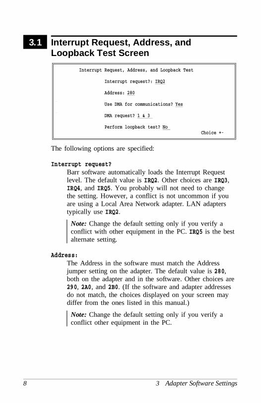
3.1 Interrupt Request, Address, andLoopback Test Screen
Interrupt Request, Address, and Loopback Test
Interrupt request?: IRQ2
Address: 280
Use DMA for communications? Yes
DMA request? 1 & 3
Perform loopback test? No Choice +-
The following options are specified:
Interrupt request?Barr software automatically loads the Interrupt Requestlevel. The default value is IRQ2. Other choices are IRQ3,IRQ4, and IRQ5. You probably will not need to changethe setting. However, a conflict is not uncommon if youare using a Local Area Network adapter. LAN adapterstypically use IRQ2.
Note: Change the default setting only if you verify aconflict with other equipment in the PC. IRQ5 is the bestalternate setting.
Address:The Address in the software must match the Addressjumper setting on the adapter. The default value is 280,both on the adapter and in the software. Other choices are290, 2A0, and 2B0. (If the software and adapter addressesdo not match, the choices displayed on your screen maydiffer from the ones listed in this manual.)
Note: Change the default setting only if you verify aconflict other equipment in the PC.
8 3 Adapter Software Settings

Use DMA for communications?Direct Memory Access (DMA) is a time-honored wayto achieve high transfer rates between memory and aperipheral device. Special hardware implements DirectMemory Access so that the software only has to initiatethe transfer of a block of memory. Without DMA,software has to process each byte of memory.
Yes Default. Use DMA. At speeds of 19,200 bps orgreater, DMA is recommended.
No DMA is not used. At speeds less than 19,200 bpsyou may want to disable DMA to avoid possibleconflicts with other equipment in the PC.
DMA request?Use of DMA increases performance. The default value of1 & 3 uses two DMA levels. Other possible settings areDMA level 1 or level 3. Which value you choosedepends on your PC type and whether you are usingfull-duplex or half-duplex communications.
On most PCs, both DMA levels 1 and 3 are available.(On the PC XT, only DMA request 1 is available.) Forfull-duplex (when DATMODE=FULL is specified in theCommunication Link) use DMA request 1 & 3. Forhalf-duplex, use either DMA 1 or 3.
Perform loopback test?The loopback test verifies that the adapter and cable areinstalled correctly and that the adapter and softwaresettings are correct. This test requires the loopback Testplug that is provided with the SCC1 cable.
No Default. Do not perform the test.
RS232 9
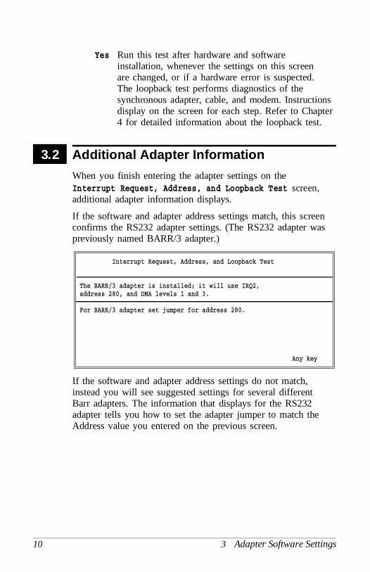
Yes Run this test after hardware and softwareinstallation, whenever the settings on this screenare changed, or if a hardware error is suspected.The loopback test performs diagnostics of thesynchronous adapter, cable, and modem. Instructionsdisplay on the screen for each step. Refer to Chapter4 for detailed information about the loopback test.
3.2 Additional Adapter Information
When you finish entering the adapter settings on theInterrupt Request, Address, and Loopback Test screen,additional adapter information displays.
If the software and adapter address settings match, this screenconfirms the RS232 adapter settings. (The RS232 adapter waspreviously named BARR/3 adapter.)
Interrupt Request, Address, and Loopback Test
The BARR/3 adapter is installed; it will use IRQ2,address 280, and DMA levels 1 and 3.
For BARR/3 adapter set jumper for address 280.
Any key
If the software and adapter address settings do not match,instead you will see suggested settings for several differentBarr adapters. The information that displays for the RS232adapter tells you how to set the adapter jumper to match theAddress value you entered on the previous screen.
10 3 Adapter Software Settings
Chapter
4 Perform the Loopback Test
Barr software features the loopback test. This test verifies thatthe adapter is functioning properly by performing diagnostics ofthe RS232 synchronous adapter, SCC1 cable, and your modem.The loopback test consists of three phases: Adapter Installationand Settings, All Adapter Functions, and Cable and ExternalModem.
Phase 1 — Adapter Installation and Settings
The first phase can be run as is — you do not need the Testplug or a modem connection. This phase verifies that theadapter is installed correctly and that all settings are correct.
Phase 2 — All Adapter Functions
The second phase requires the Test plug that comes strapped tothe modem cable. To run this phase, insert the Test plug intothe adapter. Any problem reported in this phase is with theadapter or Test plug.
Phase 3 — Cable and External Modem
The third phase requires you to set your modem to analogloopback (AL) mode, or local loopback (LL) mode on somemodems. Data does not enter the telephone line in this mode.Instead, data loops back into the receive side of the modem.
In this phase the PC sends data:
through the send side of the Barr adapter,
into the cable,
from the cable to the modem, and
through the send side of the modem.
The data returns:
through the receive side of the modem,
RS232 11
from the modem to the cable,
from the cable into the Barr adapter,
through the receive side of the Barr adapter, and
into the PC.
4.1 Loopback Test Steps
Steps for running the loopback test are listed below. Detailedinstructions for performing each step follow the list.
Step 1 At the DOS prompt, run the Barr installationsoftware. For example:
BARRSNAR i
Step 2 From the Installation Description screen:
➤ Select Interrupt Request, Address, andLoopback Test.
Step 3 From the Interrupt Request, Address, and LoopbackTest screen:
➤ Select Perform loopback test? Yes and presse.
➤ Press e to exit the Additional AdapterInformation screen.
Step 4 Follow the instructions that display on the screen foreach step of the loopback test.
12 4 Loopback Test
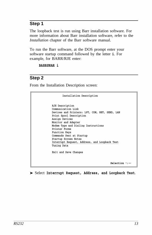
Step 1
The loopback test is run using Barr installation software. Formore information about Barr installation software, refer to theInstallation chapter of the Barr software manual.
To run the Barr software, at the DOS prompt enter yoursoftware startup command followed by the letter i. Forexample, for BARR/RJE enter:
BARRSNAR i
Step 2
From the Installation Description screen:
Installation Description
RJE Description Communication Link Devices and Printers: LPT, COM, NET, SEND, LAN Print Spool Description Assign Devices Monitor and Adapter Modem Type and Dialing Instructions Printer Forms Function Keys Commands Sent at Startup Startup Screen Notes Interrupt Request, Address, and Loopback Test Tuning Data
Exit and Save Changes
Selection xyz1
➤ Select Interrupt Request, Address, and Loopback Test.
RS232 13
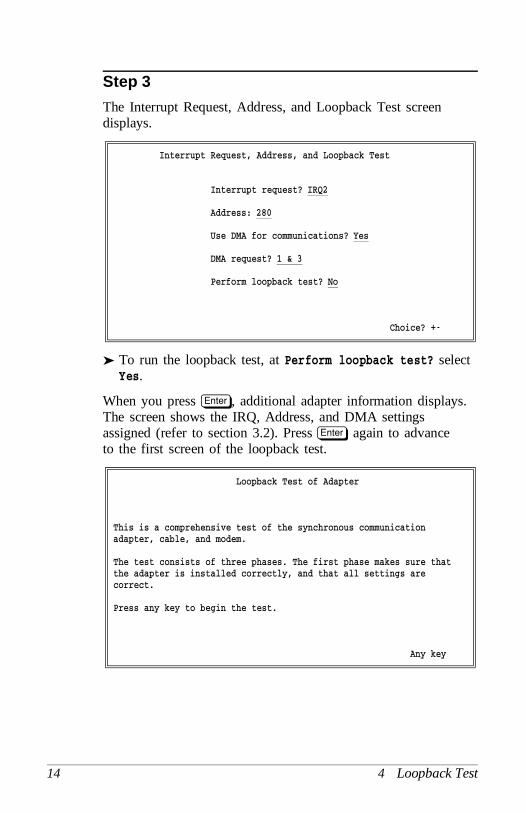
Step 3
The Interrupt Request, Address, and Loopback Test screendisplays.
Interrupt Request, Address, and Loopback Test
Interrupt request? IRQ2
Address: 280
Use DMA for communications? Yes
DMA request? 1 & 3
Perform loopback test? No
Choice? +-
➤ To run the loopback test, at Perform loopback test? select Yes.
When you press e, additional adapter information displays.The screen shows the IRQ, Address, and DMA settingsassigned (refer to section 3.2). Press e again to advanceto the first screen of the loopback test.
Loopback Test of Adapter
This is a comprehensive test of the synchronous communicationadapter, cable, and modem.
The test consists of three phases. The first phase makes sure thatthe adapter is installed correctly, and that all settings arecorrect.
Press any key to begin the test.
Any key
14 4 Loopback Test
Step 4
A different screen displays for each phase of the loopback test.Follow the instructions that display on the screen.
4.2 Loopback Test Results
If the loopback test fails, you need to know which phase failed.Watch the messages on the screen. TEST PASSED or TESTFAILED displays for each phase. Then at the end of theloopback test, a summary message displays. The summarymessage of TEST PASSED indicates all phases passed. Thesummary message of TEST FAILED indicates one or morephases failed.
A failure in Phase 1 or Phase 2 most likely indicates a problemwith the adapter. Check the following:
Is the adapter installed correctly? Make sure the adapter isfirmly in the slot.
Is the adapter making a clean connection? Try cleaning theadapter slot connectors with a pencil eraser.
Is there an Interrupt Request conflict with another adapter?If so, follow the instructions in Chapter 3 to reset the IRQ.
Is the Address specified in the program the same as thejumper settings on the Barr adapter? If not, follow theinstructions in Chapter 3 to change the Address in thesoftware.
A failure in Phase 3 most likely indicates a problem in thecable and/or modem, not in the adapter. Check the following:
Is the modem set to analog loopback (AL) mode?
Is the modem cable connected correctly?
If you are not using the supplied Barr cable, does the cablemeet the specifications in Appendix A? In particular,standard async modem cables do not work with the RS232adapter because pins 15 and 17 are not connected.
RS232 15

Notes:
16 4 Loopback Test
Appendix
A Barr SCC1 Cable Specifications
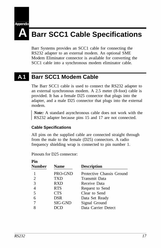
Barr Systems provides an SCC1 cable for connecting theRS232 adapter to an external modem. An optional SMEModem Eliminator connector is available for converting theSCC1 cable into a synchronous modem eliminator cable.
A.1 Barr SCC1 Modem Cable
The Barr SCC1 cable is used to connect the RS232 adapter toan external synchronous modem. A 2.5 meter (8-foot) cable isprovided. It has a female D25 connector that plugs into theadapter, and a male D25 connector that plugs into the externalmodem.
Note: A standard asynchronous cable does not work with theRS232 adapter because pins 15 and 17 are not connected.
Cable Specifications
All pins on the supplied cable are connected straight throughfrom the male to the female (D25) connectors. A radiofrequency shielding wrap is connected to pin number 1.
Pinouts for D25 connector:
PinNumber Name Description
1 PRO-GND Protective Chassis Ground 2 TXD Transmit Data 3 RXD Receive Data 4 RTS Request to Send 5 CTS Clear to Send 6 DSR Data Set Ready 7 SIG-GND Signal Ground 8 DCD Data Carrier Detect
RS232 17

PinNumber Name Description
15 TXC Transmission Signal Element Timing (DCE Source)
17 RXC Receiver Signal Element Timing (DCE Source)
20 DTR Data Terminal Ready22 RI Ring Indicator
A.2 Synchronous Modem Eliminator Cable
If your PC is located within 30 meters (100 feet) of themainframe, you can use a synchronous modem eliminator(SME) cable to directly connect the PC to the front-endprocessor or mainframe communications controller. An SMEcable eliminates the need for modems or a modem eliminatorbox, because the RS232 adapter produces the modem clocksignal, and the SME cable is wired to accept the clock signalfrom the RS232 adapter. However, the front-end processor isstill configured for a modem connection.
The RS232 adapter produces a clock signal on pin 24 fortransmit and receive timing. This clock is connected to thesend and receive clocks (pins 15 and 17) on both the RS232adapter and the front-end processor.
Barr SME Connector
An optional Barr Synchronous Modem Eliminator (SME)connector converts your Barr SCC1 cable to an SME cable.
Barr SME connector
18 A Barr Cable Specifications
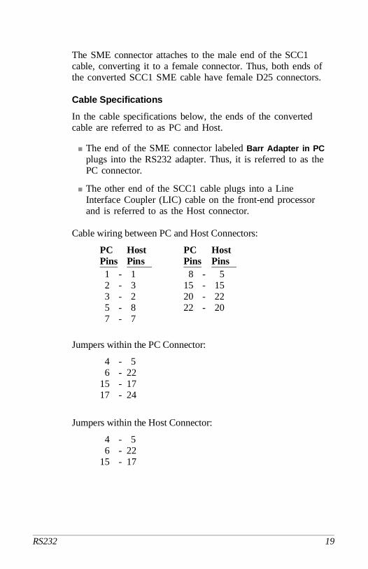
The SME connector attaches to the male end of the SCC1cable, converting it to a female connector. Thus, both ends ofthe converted SCC1 SME cable have female D25 connectors.
Cable Specifications
In the cable specifications below, the ends of the convertedcable are referred to as PC and Host.
The end of the SME connector labeled Barr Adapter in PCplugs into the RS232 adapter. Thus, it is referred to as thePC connector.
The other end of the SCC1 cable plugs into a LineInterface Coupler (LIC) cable on the front-end processorand is referred to as the Host connector.
Cable wiring between PC and Host Connectors:
PC Host PC HostPins Pins Pins Pins 1 - 1 8 - 5 2 - 3 15 - 15 3 - 2 20 - 22 5 - 8 22 - 20 7 - 7
Jumpers within the PC Connector:
4 - 5 6 - 2215 - 1717 - 24
Jumpers within the Host Connector:
4 - 5 6 - 2215 - 17
RS232 19
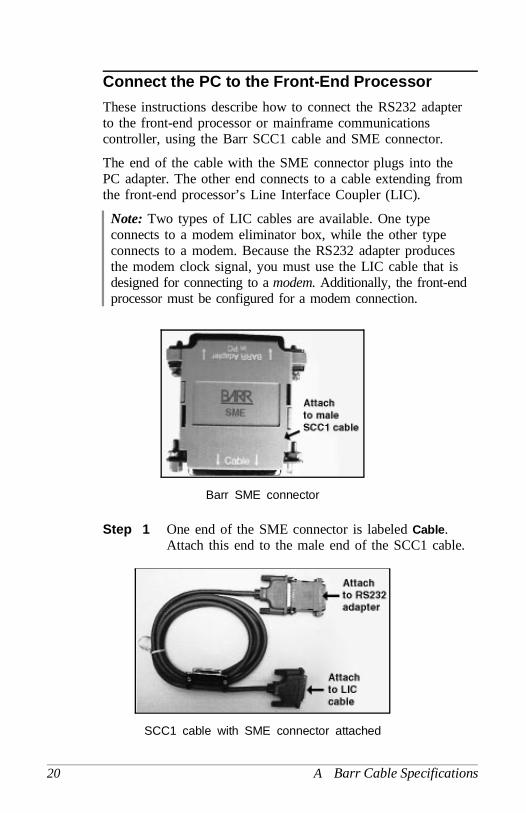
Connect the PC to the Front-End Processor
These instructions describe how to connect the RS232 adapterto the front-end processor or mainframe communicationscontroller, using the Barr SCC1 cable and SME connector.
The end of the cable with the SME connector plugs into thePC adapter. The other end connects to a cable extending fromthe front-end processor’s Line Interface Coupler (LIC).
Note: Two types of LIC cables are available. One typeconnects to a modem eliminator box, while the other typeconnects to a modem. Because the RS232 adapter producesthe modem clock signal, you must use the LIC cable that isdesigned for connecting to a modem. Additionally, the front-endprocessor must be configured for a modem connection.
Barr SME connector
Step 1 One end of the SME connector is labeled Cable .Attach this end to the male end of the SCC1 cable.
SCC1 cable with SME connector attached
20 A Barr Cable Specifications
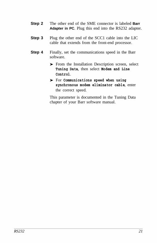
Step 2 The other end of the SME connector is labeled BarrAdapter in PC . Plug this end into the RS232 adapter.
Step 3 Plug the other end of the SCC1 cable into the LICcable that extends from the front-end processor.
Step 4 Finally, set the communications speed in the Barrsoftware.
➤ From the Installation Description screen, selectTuning Data, then select Modem and LineControl.
➤ For Communications speed when usingsynchronous modem eliminator cable, enterthe correct speed.
This parameter is documented in the Tuning Datachapter of your Barr software manual.
RS232 21

Notes:
22 A Barr Cable Specifications

Appendix
B Modems
Data transmission between the PC and the central computer iscompleted through telephone lines. The PC sends signals indigital form to a modem. The modem translates these digitalsignals to the analog signals transmitted by the telephone lines.
When the PC is transmitting, the modem converts (modulates)the digital signals to the analog signals used by the telephonesystem. When the PC is receiving, the modem restores(demodulates) the signal to digital form. The word modemis derived from modulate-demodulate.
The modems at each end of the transmission line — the host’smodem and the remote PC’s modem — operate at the samespeed [bits per second (bps)], but must also keep in step withone another. Asynchronous and synchronous are the twomethods of timing communications. Barr products supportsynchronous communications and require synchronous modems.
Asynchronous transmission communicates with a singlecharacter preceded by a start bit and followed by one or twostop bits. Essentially, the transmission message contains onecharacter with no restriction on the length of time betweenmessages. Low-speed terminals use asynchronous transmission(referred to as start-stop transmission) to communicate withinteractive systems.
Synchronous transmission incorporates a clocking mechanismcoded in the signal carrier that does not need start bits.Successive characters are sent without any intervening startand stop bits. The receiver stays in sync with the sender byconstantly evaluating the clock periods in the received signal.The transmission message consists of many characters;therefore, the inefficiency of stopping and starting betweencharacters is eliminated.
RS232 23
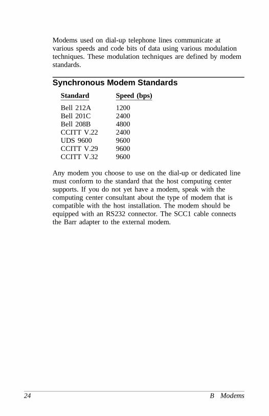
Modems used on dial-up telephone lines communicate atvarious speeds and code bits of data using various modulationtechniques. These modulation techniques are defined by modemstandards.
Synchronous Modem Standards
Standard Speed (bps)
Bell 212A 1200Bell 201C 2400Bell 208B 4800CCITT V.22 2400UDS 9600 9600CCITT V.29 9600CCITT V.32 9600
Any modem you choose to use on the dial-up or dedicated linemust conform to the standard that the host computing centersupports. If you do not yet have a modem, speak with thecomputing center consultant about the type of modem that iscompatible with the host installation. The modem should beequipped with an RS232 connector. The SCC1 cable connectsthe Barr adapter to the external modem.
24 B Modems
Federal CommunicationsCommission (FCC) Statement
Note: This equipment has been tested and found to complywith the limits for a Class B digital device pursuant to Part15 of the FCC Rules. These limits are designed to providereasonable protection against harmful interference in aresidential installation. This equipment generates, uses, andcan radiate radio frequency energy and if not installed andused in accordance with the instructions, may cause harmfulinterference to radio communications. However, there is noguarantee that interference will not occur in a particularinstallation. If this equipment does cause harmful interferenceto radio or television reception, which can be determined byturning the equipment off and on, the user is encouraged totry to correct the interference by one or more of thefollowing measures:
Reorient or relocate the receiving antenna.
Increase the separation between the equipment and receiver.
Connect the equipment into an outlet on a circuit differentfrom that to which the receiver is connected.
Consult the dealer or an experienced radio/TV technicianfor help.
You also are warned that any changes to this certified devicewill void your legal right to operate it.
Note: A shielded and grounded cable is required.
RS232 25

Notes:
26 FCC Statement

Warranty Information
Software License Agreement:Single-UserBarr Systems, Inc. (‘‘Barr Systems’’) grants and Licenseeaccepts the terms and conditions of this agreement whichprovide a non-transferable and non-exclusive license to use thesoftware program (‘‘Licensed Software’’) enclosed herewith onone single-user workstation, so long as Licensee complies withthe terms of this agreement. Licensee’s rights hereunder arethose of a licensed user only and the Licensed Software shallat all times remain the property of Barr Systems.
Licensee agrees to pay for licenses for additional user copies ofthe Licensed Software if Licensee intends to, or does, use it onmore than one single-user workstation at a time.
Acceptance
Licensee understands that the use of the Licensed Software, orthe use of any of the computer hardware (the ‘‘ProductHardware’’) purchased from Barr Systems, constitutesacceptance of the terms and conditions of this Software LicenseAgreement and this Limited Warranty with respect to theProduct Hardware and the Licensed Software.
RS232 27

Maintenance and Limited Warranty
The Licensed Software and the Product Hardware are underwarranty for a period of one year following the date theLicensed Software and the Product Hardware were mailed orotherwise made available to Licensee. Support for the LicensedSoftware and the Product Hardware beyond the initial one-yearwarranty period may be obtained by Licensee through thepurchase of an annual Licensed Software and ProductHardware Maintenance Agreement from Barr Systems.
Barr Systems warrants that the Licensed Software and theProduct Hardware will perform substantially in accordancewith the published specification statement, documentation, andauthorized advertising. Provided Barr Systems is notified ofsignificant errors during the warranty period, Barr Systemsshall, at its option:
(1) Provide telephone support (Phone 800-BARR-SYS or352-491-3100) to correct significant and demonstrableLicensed Software program or documentation errorswithin a reasonable period of time, or
(2) Repair or replace the Product Hardware within areasonable period of time if it should prove defective, or
(3) Provide or authorize a refund of the purchase price ofthe Licensed Software or the Product Hardware.
Transfer or Reproduction
The Licensee shall not sell, assign, sublicense, copy, orotherwise reproduce in whole or in part, or transfer any copiesof the Licensed Software to another person, subsidiary, parentcompany, or other company without the express writtenpermission of Barr Systems. Barr Systems has the legal right totrace serial numbers and to take legal action if these conditionsare violated.
28 Warranty

Limited Warranty
THE LICENSED SOFTWARE AND THE PRODUCTHARDWARE ARE PROVIDED ‘‘AS IS’’. ALLWARRANTIES AND REPRESENTATIONS OF ANYKIND WITH REGARD TO THE LICENSED SOFTWAREAND THE PRODUCT HARDWARE ARE HEREBYDISCLAIMED, INCLUDING IMPLIED WARRANTIESOF MERCHANTABILITY AND FITNESS FOR APARTICULAR PURPOSE, EXCEPT THAT BARRSYSTEMS WARRANTS THAT THE LICENSEDSOFTWARE AND THE PRODUCT HARDWARE, WHENDELIVERED, WILL OPERATE SUBSTANTIALLY ASDESCRIBED IN THE USER DOCUMENTATION ORGUIDE. UNDER NO CIRCUMSTANCES WILL BARRSYSTEMS BE LIABLE FOR ANY CONSEQUENTIAL,INCIDENTAL, SPECIAL OR EXEMPLARY DAMAGES,EVEN IF APPRISED OF THE LIKELIHOOD OF SUCHDAMAGES OCCURRING. LICENSEE’S SOLE ANDEXCLUSIVE REMEDY FOR THE BREACH OF ANYPROVISIONS OF THIS AGREEMENT OR FORBREACH OF WARRANTY SHALL BE LIMITED TOTHE REPAIR OR REPLACEMENT OF THE LICENSEDSOFTWARE OR THE PRODUCT HARDWARE BYBARR SYSTEMS, OR THE REFUND OF THEPURCHASE PRICE. THE CHOICE OF REMEDIESSHALL BE MADE AT THE OPTION OF BARRSYSTEMS.
Licensee and Barr Systems agree that the Licensed Softwareand the Product Hardware are not intended for use by Licenseeas ‘‘consumer goods’’ under state or federal law.
This warranty gives you specific legal rights, and you may alsohave other rights which vary from state to state. Some statesdo not allow limitations on how long an implied warranty lastsor exclusion or limitation of incidental or consequentialdamages; therefore, the limitations set forth in this agreementmay not apply to you.
RS232 29
Copyright
The Licensed Software is the sole and exclusive property ofBarr Systems, which is licensed and distributed by BarrSystems pursuant to a nonexclusive software license agreement;it is an unpublished work, with all rights reserved, and containsconfidential information and trade secrets proprietary to BarrSystems. Disassembly or decompilation is prohibited; patentspending.
Licensee acknowledges and agrees that the Licensed Softwareis copyrighted and that Licensee is not authorized to reproduceany copies of the Licensed Software, nor allow others toreproduce any copies except in accordance with instructions inthis manual. Licensee further agrees that Licensee does nothave, and shall not gain, any exclusive copyright rights withregard to the Licensed Software.
Miscellaneous
These definitions shall govern the use of terms in thisagreement: ‘‘Barr Systems, Inc.,’’ a Florida corporation, whoseaddress is P.O. Box 147015, Gainesville, Florida 32614-7015,is the author and owner of the Licensed Software; ‘‘Single-userworkstation’’ is defined to include any device from which theenclosed Licensed Software may be used or accessed;‘‘Multiple user’’ is defined as more than one single-userworkstation. Where networks of terminals are used, each suchterminal shall be counted as a separate single-user workstationand must be licensed individually; ‘‘Licensed Software’’ is thecomputer program licensed to Licensee, regardless of the formin which Licensee may subsequently use it, and regardless ofany modification which Licensee may make to it. The LicensedSoftware is distributed in machine-readable form only and nosource code is provided; ‘‘License’’ means this agreement andthe rights and obligations which it creates under the UnitedStates Copyright law and the laws of the several states andterritories of the United States; ‘‘Licensee’’ refers to the enduser (individual or company); ‘‘Product Hardware’’ refers to anycomputer hardware manufactured, sold or distributed by BarrSystems.
30 Warranty

This is the entire agreement between Barr Systems andLicensee, and it cannot and shall not be modified by purchaseorders, advertising, or other representations of anyone.
All notices or other communications given under thisagreement shall be in writing, sent to the address presentedabove as the principal place of business of Barr Systems, orsuch other addresses as Barr Systems may designate in writing.
Both parties acknowledge that they have read all the terms ofthis agreement, understand it and are authorized to enter into itand agree to be bound by its terms and that it is the completeand exclusive statement of the agreement between the parties,which supersedes all proposals, oral or written.
If any provision, or portion thereof, of this agreement shall bedeemed invalid and/or inoperative, under any applicable statuteor rule of law, it is to that extent to be deemed omitted andshall have no effect on any other provisions of the agreement.
This agreement shall be construed and enforced in accordancewith the laws of the State of Florida and is deemed enteredinto at Alachua County, Florida, by both parties.
RS232 31

Notes:
32 Warranty