Embed Size (px)
Citation preview

CURSHL: A HIGH-PRECISION FINITE ELEMENT FOR
r)SHELLS OF ARBITRARY SHAPE
by
G.R. Cowper
A.H. Hall, Head, F.R. ThurstonStructures and Materinls Section Director

SUMMARY
CURSHL is a high-precision.finite element,for the -linear static stress analysis of thin elasticshells of quite general shape. The element is-a fully-conforming displacement element of curvilinear tri-angular form. The theoretical basis of the element ispresented in fairly complete detail, and some aspectsof the organization of the computer program arediscussed. The performance of CURSHL is examinedwith regard to accuracy of numerical integration,computation time, and representation of rigid-bodymodes.
(iii)

TABLE OF CONTENTS
SUM liARY' .......................... .................... (ii)
ILLUSTRATIONS .................................................... (v)
1.0 Introduction ...................................................... 1
2.0 Rdsumd of Formalirs from Shell Thenry ............................. 2
2.1 Geometric Parameters ......................................... 22.2 Membrane and Bending Strains ................................ 512.3 Stress-Strain Relations and Strain Energy ...................... 112.4 Physical Components ............................... ........ o 9
3.0 Interpolati(il Functions for Displacements .......................... 11
3.1 Local Coordinates ... ; ...... ............................... 123.2 Tangential Displacements ........ ............................. 143.3 Normal Displacement ...................... , .................. 16
4.,0 Stiffniess Matrix ............................................ ... 22
4.1 Outline of Calculation ......................................... 224.2 Evaluation of f ei ........................................... 24
4.3 Input Data for Matrices [-B] and [E ......................... 25
4.4 Efficient Calculation of Strain Energy Density ............. 27
5.0 Load Vector ...................................................... 28
6.0 Performance of CURSHL ........................................... 29
6. 1 Accuracy of Numerical Integration ............................. 29
6.2 Computation rime ............................................. 30
6.3 Rigid Body Modes ............................................ 30
7.0 References ....................................................... 32
TABLES
Table Page
I Strain-Displacement Matric [ B] ............................... 34
I1 Elasticity Matrix [E] ....................................... 35
III Transformation Matrices for Tangential Displacements .......... 36
IV Trans3formation Matrices for Normal Displacement .............. 37
V Numerical Integration Formula Used in CURSHL ................ 38
(iv)

TABLES (Cont'd)
Table Page
VI Transformation Matrix for Generalized Displacements .......... 39
-' VII Comparison of Solutions for Pressurized Spherical Cap .......... 40
VJHI Computing Times for CURSHL ................................. 41
IX Eigcnvalues of IX = XIMIX, where K is the CURSHL StiffnessMatrik ......... ......................................... 42
ILLUSTRATIONS
Figure Page
1 Local-Coordinates ........................................... 44
2 Positive Direction of Physical Components of Displacement andRotation ................................................. 45
3 Positive Directions of Physical Components of Stress Resultantsand Bending Moments ..................................... 46
4 Diagram of Spherical Cap. Uniform Applied Pressure ........... 47
(
(v)

1.0 Introduction
CURSHL is the acronym both of a high-precision finite
element for the static analysis of thin shells and of the
associated computer program. The element is a fully conforming
displacement element of curvilinear triangular shape which
utilizes the same inteirpolation functions and generalized
displacements as previous high-precision elements for plate
bending, plane stress, shallow shells and cylindrical shells.
Continuous Kirchoff constraints are used. The computer program
generates the stiffness matrix and consistent load vector for a
single element. Variable thickness and elastic modulus, as well
as therhial loadb, can be accommodated by the program but at
present the program is limited to linear elastic isotropic material.
The program provides the option of generating a stiffness matrix
based on either Koiter-Sanders shell theory, Donnell-Vlasov shell
theory, or shallow shell theaoy. Except for a requirement of
smoothness the shape of the shell is virlually unrestricted.
A general description of CURSHL was first given at CANCAM'71 [lO]*. An amplified description and an outline of the
considerations which guided the development of CURSHL were given
in Reference [1], which also included several examples of CURSHL's
performance. Because the emphasis in these references was on the
performance and accuracy of the element, many details of the
theoretical and computational aspects were omitted. The purpose
of the present report is to describe in fairly complete detail
the underlying theory and to oatline the organization of the
computer program. In the pages which follow the relevant items
from shell theory are presented, formulas for the interpolation of
displacement within an element are derived, and the method of
calculation of the stiffness matrix is described. In addition,
certain computational details of the program are discussed.
Finally, the element is tested in a small number of example problems
Numbers in square brackets denote references at the end of the
text.

-2
in order to iilust~'te its accuracy.
2.0 Rdsum6 3f Formulas from Shell Theory
The required formulas from shell theory are assembled
here for ease of reference. General tensor notation is used in
order to avoid unnecessary restrictions on the shape of t,.e shell
or on coordinate systems. Of the multitude of existing first-
order shell theories, the theory of Koiter-Sanders can claim,
with reasonable justification, to be the best [4]. It is
therefore used as the main theoretical basis of the element. It
happens that the equations of the simplified theories of Donnell-
Vlasov and of shallow shells are obtainable from the Koiter-Sanders
equations by a few simple modifications. Since the latter "•neories
are widely used, they are made optionally available in the computer
program.
The treatise of Green aoJ Zerna [2] is the source of the
formulas for the geometric parameters, including the approximate
formulas which may be used when the shell is shallow. The
equatio:,s of Koiter-Sanders shell theory are taken from the papers
of Koiter [3], and of Budiansky and Sanders[k]. Tensor notation
following the conventions of Reference [2] is used throughout this
section.
2.1 Geometric Parameters
(i) General Shell
Let 01, 02 be curvilinear coordinates on the shell's
middle surface. Let the middle surface be defined by the position
vector r = 8,, 2 ) whose Cartesian components are x, :,, z. The
covariant metric tensor is
aX = r,' r,l = x,x ,P + Y)XYP + zXz,I (2.1)
while the contravariant metric tensor is given by
1a 12 = a22 a 2aI =a 2 2 /a, a =a = -a 1 2 /a, a = a11/a (2.2)

where a = a11 a2 2 - a.2a;2, (2-3)
The unit normal vector is+
(r,= X ,.2)/1r,l X r,•2 (2.4)
and we note
ir., x r.21 = /a (2.5)
The covariant and mixed curvature tensors are
b = nr.r,, = nxxXII + ny yVX + n (A .6)
A pb =a b
The contravariant base vectors are given by
a = a • (2.7)
and the Christoffel symbols are
P = arP (2.8)
= aXP(x,1 P V + Y'pY YPV + zpzpv)
The formulas for covariant differentiation of first and second
rank covariant tensors are
AXli = AXi - rP A (2.9)XP' P
XAPl = A -rvA - rA (2.10)
Xp~v XV P1l i' 1VpX
In addi'Pion to the foregoing standard formulas, expressions
for the covariant derivatives of the mixed curvature tensor are
needed. To obtain these we first differentiate (2.6) to get
b XV n.r,XV + nV. (2.11)
---
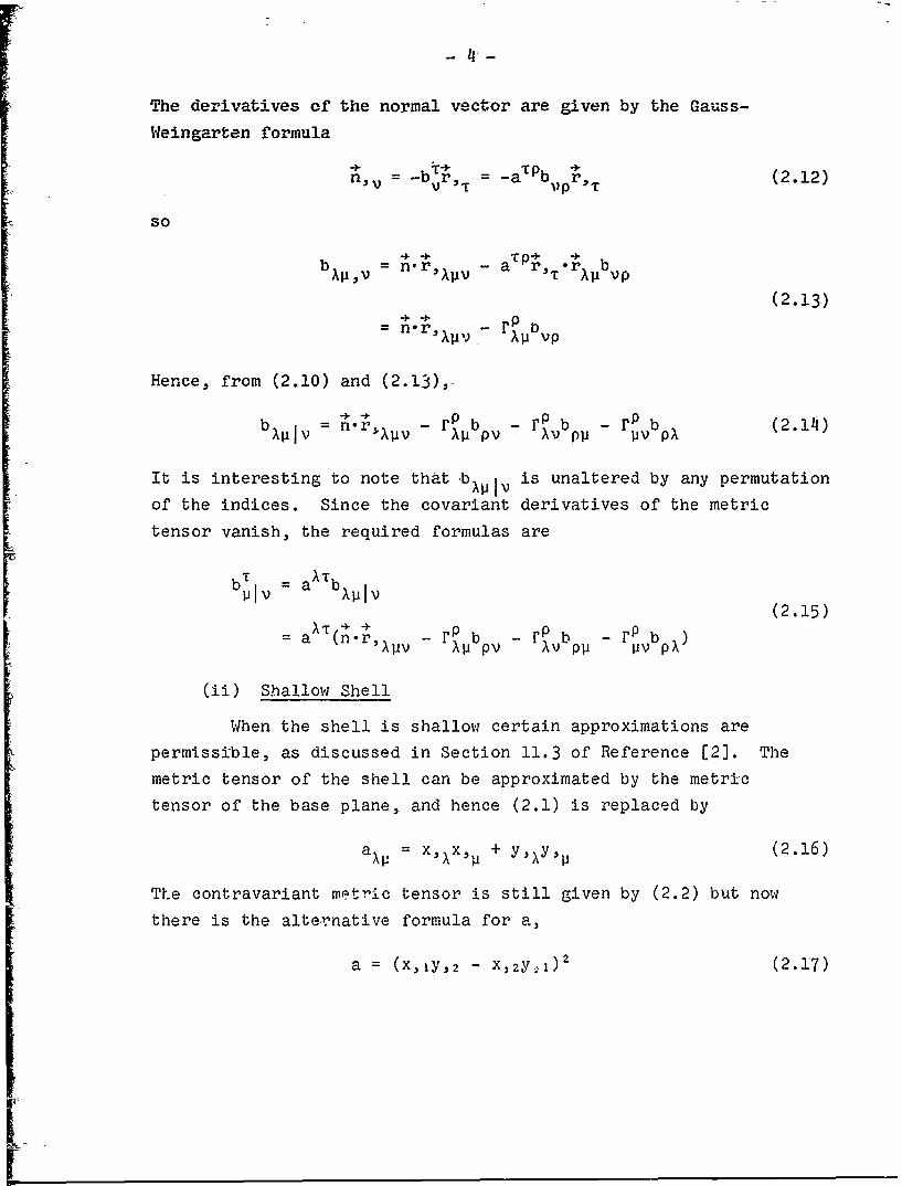
The derivatives of the normal vector are given by the Gauss-
Weingarten formula
n~v= -bVr (2.12)
so
b XP3V= n - a P.,T rXPbVP
(2.13)
AP )AP VP
Hence, from (2.10) and (2.13),-
b = - rp b - P b - b (2.14)bPIV n'iPV pv Pv P11 V pX
It is interesting to note that +b~iiv is unaltered by any permutation
of the indices. Since the covariant derivatives of the metric
tensor vanish, the required formulas are
b T aXT blplb = Iv(2.15)
a n r(.~,~j - rp1 b - rP b -F b p b
(ii) Shallow Shell
When the shell is shallow certain approximations are
permissible, as discussed in Section 11.3 of Reference [2]. The
metric tensor of the shell can be approximated by the metric
tensor of the base plane, and hence (2.1) is replaced by
a = xxx,.' + y,)y, ' (2.16)
The contravariant metric tensor is still given by (2.2) but now
there is the alternative formula for a,
a= (x,Iy, 2 - x, 2 y;l) 2 (2.17)

5
Hence%, within the shallow shell approximation,
T , = r = (X, 1 Y, 2 - x, 2 y,l) (2.13)
where the correct sign of the expression for /a was
determined from the particular case 01 = x,6 2 = y.
The unit normal can still be calculated from (2.4),
and in view of (2.18-), the result agrees with the usual shallow
shell approximation for the normal. That Is, the z-component
of n is 1 while the other two components are equal to the
negative gradient of z. If, in turn, this result is used in
(2.6) to calcuilate the curvature tensor the expressions
obtained agree with the Usual shallow shell approximation,
= (2.19)
where the double stroke denotes covarlant differentiation in
the base plane.
The Christoffel symbols for the base plane are obtained
by replacing r in (2.8) by R, where ý is the component of +r
lying in the base plane, at the same time using (2.16) to
calculate the metric tensor. Thus
r = a = axP(x,X1 + y, y ) (2.20)_1 J 'p
In summary, for shallow shells formula (2.1) is
replaced by (2.16) and formula (2.8) by (2.20), but the formulas
for a , n, and bX1 remain valid.
2.2 Membrane and Bending Strains
The membrane strain tensor is related to th3
displacements by
XP+ u2) - b,•(uXX1 (2,21)
- U + +u )-r, u - b',(u 11.,, X• X1 P XP

and this relation applies to all three of Koiter-Sanders,
Donnell-Vla5ov, and shallow shell theories.
In Koiter-Sanders theory the rotations of the normal
ýX and the surface rotation X-"p are given by
= - w, - bU (2.22)
(U - uVX P - u11U ) (2.23)
and the bending strain tensor is
K + + 1(b P + b1w)11 2 11 1 X 2X lip 11iXp
= - w,• +1, W,
(2. 24)
.(bPu + bPu ) + 2(bpu + bP u
"+ - bP + r~Pb.+ rbPb+)u
In Donnell.-Vlasov theory and in shallow shell theory the
rotations of the normal are approximated by
X= - w,X (2.25)
and the bending strain tensor is given by the relatively
simple formulas
K =+4 )+= -w
(2.26)
= - W,l + rP w
These strain-displacement relations may be summarized by the
matrix relation
je) = [B]{d} (2.27)

where (e) is a column vector of strains,
10T. = 1E1E2E2K12C212- (2.28)
and fill is a column vector of displacements ýftd their
derivatives,
{d]T = (u 1 ,u 1 , ,)1,z,'z.UzlUZzNW,1,W,22,I ,wlZW, 2 2 1 (2.29)
The matrix [B] is displayed in Table I,
2.3 Stress-Strain Relations and Strzin Energy
The stress resultants and. bending ronent-s are related
to the membrane and bending strains 1'.,v
n -P = CHXVP E (2.30)
m = DHAXPT .2.31)
where C is the stretching rigidity, D the flexural rigidity,
and
HPT {(l-v)(aa + a PaPT) + 2va "apT} (2.32)
For homogeneous shells of thickness t,
C = Et/(l-vZ), D = Et /12(l-v 2 ) (2.33)
For laminated or sandwich shells other expressions for C and D
may be appropriate and their use is not ruled out. However
(2.30), (2.31), and (2.32) apply only to isotropic shells in
which there is no coupling in the stress-strain relations
between bending and stretching.
The strain energy density is
dU/dA = A(nA'E C + mKAPK)
(2.34)
= '(CH X1 C PT + DHX KAPTKlK PT

-8-
and this may be written in matrix shorthand as
dU/dA = R{e) [E]{e} (2.35)
The matrix CE] is displayed in Table II.
When thermal expansion is considered the s/ ,ess-strain
relations are modified to
n = CH-:PPTCpT (Ea/(I-v))TR aA (2.36)
ml' = DHXIPPTK - (Ea/(X-1))T1aAlJ (2.37)PT M
where ' is the coefficient of thermal expansion and TR and
[TM are the resultant and the moment of the temperature T across
the thickness. That is
t,/2T TR f 'V()dý (2-38)
-t/2
S~t/2
TM = t ýT(ý)dý '(2.39)-t/2
where • is the coordinate in the thickness direction of the shell.
Formulas (2.36) and (2.37) apply to homogeneous shells and would
have to be modified for laminated and sandwich shells. The
thermal strains do not affect the expression for strain energy, but
instead influence the expression for the virtual work of the
external loads.
We suppose that the shell is acted upon by a distributedSload per unit area p The contravariant components of arepcn a p are p
in the tangent plane and pn normal to the shell. The virtual
work per unit area of the applied loads, including the contribution
of thermal effects, is
dV/dA = pX u + pnw + (Ea/(l-v))(TRa XPep + rMaxpe ) ( 2 . 4 0 )

-~9-
I or, in matrix notation
dV/aA = {IT {d' + {Q}T {e} ( 2 .41)
where
{p}T = {pfl,0,p2 0,0,n 0,0,0,0,0} (2.412)
(PT = p1,1,O22 1O1O12
{Q}T = (Ea/(.Lv)){TRa 1 .2T aR R TRa 2 ,TMa' ,2TMa a TMa221 (2.43)
2.4 Physical Components
The tensor components of stress or displacemnent are notthe same as the physical components of these quancities. It is,
of course, the physical components which ar.ý Ultimately sought,
although tensor components are used in setting up the stiffness
matrix.
The physical components of displacement u, v, w, resolved
along, bhe covariant base vectors, are related to the tensorcomponents by
Ti = (a'1"ui + a22Yý1
1= (a 1 2 u1 + a2 %u,)/ a22 (2,44)
w=w
The contravdriant tensor components of load are related
to the physical components P1, P2, Pn3 by
p 1 14/aV-11 p2 = P2//', P n (2.45)
The physical stress resultants N and the physical
bending moments M are related to their tensor counterparts
by

- 10
Nil = n1 1 /(a 1 l/a 1 l), N12 = n 2 /a, N2 2 = n 2 2 V(a 2 2/a 22 ) (2.46)
All = mll/(aall/all), M1 2 =.-m 1 2 /a, 1 22 = m 2 2 /(a2 2 /. 2 2 ) (2.47)
Tie physical components of the rotation of the normal
),4)2, are related to the tensor components by the f6rmulas'
d=',A4)+ a12 ra) Ii
(2.48)
T2 (a 2 1ci+ a 2 24W2 ) /a2
which are the same as the corresponding formrlas for the
displacements. According to Glockner [12] the physical component
of the surface rotation • Js given by
Q= e W a/2
(2.49)(Uz2,1 - ul, 2 )/vr(.0
where E: is the alternating tensor.
We note in passing that the rotation vector Q is given by
S =ea rB + Qn (2.50)
The conventions for the positive directions of the
physical components of displacement, rotation, stress resultants,
and bending moments are illustrated in Figures 2 and 3. In the
figures, the surface coordinates have been denoted as a, 6,
rather than el, 02. The positive direction of the normal is such
that the normal vector forms a right-handed triad with the
tangent vectors along the a-curves and the s-curves. Figures
2 and 3 are intended to show non-orthogonal ccordinates. The
directions of the stress resultants are parallel to the
coordinate curves. The vectors which represent che bending
moments are orthogonal to the coordinate curves, and, consistent
with this, the components of bending stress are parallel to the
coordinate curves.

-41
3.0 latErpolation Functions for Displacements
At this ,point we drop the tensor notation of the preceding
section and introduce a,3 to denote the general curvilinear
coordinates on the. shell surface, and u, v, w to denote the
covariant tens6r components of displacement. The coordinates
a,$ need, not be principal nor orthogonal.
The curvilinear triangular element on the shell surface
can. be imagined mapped on to the a-$ plane. The edges of' the
element are defined by specifying that they are straight lines
in the a-$ plane.
The displacements in CURSHL are interpolated by the same
functions which have been used in previous high-precision
elements [5,6,7,8]. The in-plane displacements u,v are taken
as complete cubic polynomials in a.ý, while w is taken as a
restricted quintic polynomial in a,O. In keeping with this choice
of di'splacement functions the generalized displacements are the
values of u, au/a', au/a3, v, 3-,r/Da, 3v/30, w, 3w/ce, 3wlý,
a2 w/3a2 a2 w/qaa, 3 2 w/@ý 2 at the three vertices of the element,
for a total of 36 degrees of freedom. Centroidal displacements
u.c,vc, are used temporarily as degrees of freedom during the
development of the stiffness matrix but are later eliminated by
static condensation.
The choice of interpolation functions and generalized
displacements assures that the element is fully conforming
provided the shell surface satisfies certain smoothness conditions.
For Koiter-Sanders theory these conditions are that the shell must
be smooth and have continuous curvatures. For Donnell-Vlasov
theory and for shallow shell theory it is sufficient that the shell.
is smooth. These conditions are discussed in more detail in
References [1] and [71.
The order of the discretization error of a conforming
finite element depends on the choice of interpolation functions,
and can be predicted by the Taylor's series test introduced by

- 12 -
McLay [11. The application of the test to the present, element
is essentially the same as in tests of previous high-precision
elements for flat plates [5] and shallow shells [7]. The result
is that the discretization error-is of order h6 where h is a
typical linear dimension of an element. The Taylor"'s series test
also shows that the interpolation functions for w on the one hand
and for u,v on the other are matched, in the sense that they
provide equal orders of accuracy in the strains.
Further discussion of the choice of interpolation
functions is contained in Reference [1].
3.1 Local Coordinates
Let the vertices of the element be numbered 1,2,3 in
counterclockwise order when viewed from the positive side of the
element. Let the shell coordinates of the vertices be
(ali,1), (a 2 ,0 2 ), (a 3 ,-g 3 ), respectively as shown in Figure 1.
In order to develop formulas relating the displacements
within an element to the generalized displacements it is helpful
to introduce a system of local oblique coordinates •,r. The
ý-axis is taken to coincide with the 1-2 edge of the element and
the n-axis with the 1-3 edge, as shown in Figure 1. Further, the
local coordinates are scaled so that g runs from 0 to 1 along
edge 1-2 while ri runs from 0 to 1 along edge 1-3. The relation
between a,3 and •,n is easily established as
a i+ (a-1~+ (a3-al)fl
(3.1)
= 8 + (82-81)• + (R3-01)fl
Derivatives with respect to local and global coordinates
are related by

[ 1 13
Vn= f12 3/aa + f2za/30
3232= f23/O+ 2f'11£2 j32 /3ca3 + f 2 12a2 /302 (3.,2)
a/En= filfiaaa/3acz + (f11f22 + f21f1 2 )a2/aa3O +~ f~£2 a2
32/ = 12 22/act2 + 2f12 f2 2 32/act;3 + f2223/302
3/a= dj33 + d2 1 3/ý3n
= dj~z3/3E + d223J/3n
32;2= d 2/a + 2diidajD2/a~an + d2 l2 aO2/an? (3.3)
= dild 1 2a2/aE2 + (d11d22 + dzidjj)3ý/aý3n +d2d2 2/n
2/2=d 1 2 22 /aE2 + 2d,2d22 3 2/ýETh + d2 2a% 2 /an2
where
f'ii - alf12 a3 - a
f~l 02 ý1f22 ý3 - 1
di 03 - ýi)/f d12 =-(at 3 - ca1)/f (3.14)
Vd 2 1 (0 - ý1 - V)/ d22 =(Ac 2 -Ctl/f
f = (a2 - al)(03 - ý1 - (a3 - al)(02 - 1
[ The Jacobian of the transformation is equal to f,

- 14 -
3.2 Tangential Displacements
The tangential displacement u is taken as a complete
cubic polynomial in the shell coordinates a,O, or equivalently
as a complete cubic polynomial in the lodal coordinates, thus
u = a, + a2E + a3n + a4 2 + asgn + a6nz + a7g3
(3.6)+ a8 g2n + ag n 2 + a1on3
The corresponding generalized displacements are the values of
u and its first derivatives with respect to a,O at the three
vertices of the element. In order to match the number of
generalized displacements the number of coefficients in
(3.6) the displacement u c at the centroid is introduced as an
additional generalized displacement. Later uc will be eliminated
by static condensation.
Denote the values of u, Du/Dg etc. at vertex number 1 byui, uV, etc. Since the lQcal coordinates of vertices 1,2,3, and
of the centroid are (0.0), (1,0), (0,1), (1/3,1/3), respectively,
the following relations are obtained from (3.6)
ul = a,
Ugl = a 2
U = a 3
u= ai + a 2 + a4 + a 7
U ý2 a2 + 2a 4 + 3a7
unT = a3 + a5 + a8
U3= al + a 3 + a6 + alo
U 3 a 2 + as + a9
u = a3 + 2a6 + 3ajo
u = a, + (a 2 +a 3 )/3 + (a4+as+a6)/9 + (a7+aa+a0+ao)/27
VC

-15"-
These relations may be explicitly inverted to give
{Au) = [Tu]{Wtl' (3.8)where {Au}, {Wu1 are the column vector.
{Au}T = {al,,a2,a 3, ... a(o9
S uuu3,,u u} (3.10)
u T1T
and' the matrix [Tu] is displayed in Table III.
Let {Wu} be the column vector Of generalized displacements
{Wu}T = {u,,u1a8u1,u'2,u2,u2 02,u3 ,u:ý,u38,uc} (3.10a)
where ula, etc. denotes the value of 'u/•a at vertex number 1,etc. The relation between {Wul and {W1} is evident from equations
(3.2) and may be written in matrix form as
{W1} = [Ru]{Wul (3.11)
where [Ru] is given in Table III. Hence the polynomial
coefficients of (3.6) are related to the generalized displacementsby
{Au} = [Tu][Ru](Wu} (3.12)
Given the generalized displacements, the polynomial coefficients
can be ca-Ijulated from (3.12) and, in turn, the values of u andits derivatives can be found from (3.6). A similar relation
applies to the displacement v.
An advantage of using local coordinates is that [Tu] can
be found explicitly and is simple in form.
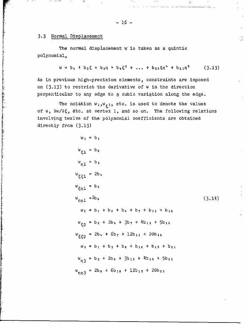
3.3 Normal Di-splacement
The normal displacement w is taken as a quintic
polynomial,
w =b, 4- b 2 ý + b 3 n I b 42 + ... + bzo~nj + b 2 1 n 5 (3.13)
As in previous high-precision elements, constraints are imposed
on (3.13) to restrict the derivative of w in the direction
perpendicular to any edge to a cubic variation along the edge.
The no tatioh w1 ,w•,, etc. is used to denote the values
of w, 3w/ag., etc. at vertex 1, and so on. The following relations
involving twelve of the polynomial coefficients are obtained
directly from (3.13)
w b2
w ~b2W b b3nll
W = 2b4
wnn = 2b6 (3.14)
w2 = b, + b 2 + b4 + b7 + bil + b 1 6
w = b2 + 2b4 + 3b 7 + 4b1 1 + 5b1 6
w g2= 2b4 + 6b7 + 12bii + 20b16
w3 bj + b 3 + b6 + blo + b15 + b21
w Ti3: b3 + 2b6 + 3blo + 4bjs + 5b21
w p13 =2b6 + 6b 1 o + 12bis + 20b 2 l

17
These relations can be explicitly inverted to give
bi = w,
b2 = W
b3 = W
b 4 W /2
bs = w•1i
b6 = Whn 12 '(3.15)
b 7 :-low, - 6w~l - (3/2)w• 1 + lOw2 4w 2 + w•2/2
bl 0 = -low, - 6w - (3/2)w + 1Ow 3 - 4wn3 + w /2
bil = !5wi + 8w + (3/2)w - 15w. + 7wý2 -
b1 s = 15w, + 8w.1 + (3/2)w nnl 15W3 + 7wn3 - 3
b16 = -6w - 3 - w /2 + 6wv - 3w 2 + /2
b2l = - 6w, - 3w., - Wrlr /2 + 6w3 - 3wrI3 + w nr /2
To obtain formulas for the other coefficients, the
constraints on the derivatives of w must be considered. Since
terms of quartic and lower degree give first derivatives which
vary at most cubically, the constraints affect only the six
quintic terms in (3.13).
With reference to Figure 1, the derivative in the
direction perpendicular to the edge 1-2 in the a-$ plane is
given by
Dw/3n = sin 0 3w/Da - cos 0 aw/U (3.16)

-18-
where
sin 0 = (02-01)/V'33, COS 0 =(a2--CI."r-33
(3.17)
S 3 3 = (CQ-al) + (02-01)2
Transforming (3.16) to derivatives with respect to ý,n ,gives,
after some manipulation
aw/an = {S32Dw/3-s3w/3q}/(f/33) (3.18)
where
S32 = (a2-al)(a 3-Ul) + (02-31)(33-01) (3.19)
On edge 1-2, on which q=0, the contribution to the term in
parentheses in (3.18) from the quintic terms in (3.13) is simply
(5s3 b16-s3 3bl 1)g4 (3.20)
and hence the condition for cubic variation of the derivative
perpendicular to the edge 1-2 is
b17 = (5s 3 2 /s 3 3 )b 1 6 (3.21)
The above equation determines b 17 since b1 6 is already known
from (3.15).
Similarly, the constraint along the edge 1-3 leads to
the result
b 2 o = (5s 3 2 /s2 2 )b2 1 (3.22)
where
S 2 2 = (a3-al) 2 + (03-0 1)2 (3.23)
The constraint along the edge 2-3 leads to the equation
s 2 1 (5b 1 6 -4b17+3b 18 -2b 1 9+b2o) = S3)(b 1 7 -2U 1 a+3blg-4b 2 o+5b 2 1 ) (3.24)

I where
S21 = (c3-ct)(c3-a2) + (3-01)(3-a2)(3.25)
S31 = (a2-al)(a 3-q2 ) + (2-01)(03-ý2)
[The following four relations are obtained directly from
(3.13)
= b3 + bs + be + b12 + b1 7
w = b5 + 2ba + 3b12- + 4b17 (3.26),
w = b2 + bs + b9 + b14 + bz0
w~q 3 = bs + 2b9 + 3bi,• + 4b 2 O
and these can be solved to give be, b12 , bg, b14 in terms of
quantities already known,
be = - 3wql - 2w,,I + 3wn2 - w q2 + b17
b1 2 = 2w + w 1 - 2w 2 + w g - 2b 1 7 (3.•27)
be = - 3w,1 - 2 w lI + 3w. 3 - w,3 + b2 0
b 1 4 = 2w +w -2w +w -2baC
To determine the remaining coefficients b 1 3 , ble, b9,g
there are the relations obtained from (3.13)
w9 3 - 2(b 4 +be+bl 3 +b1 3) (3.28)
Wnn2 = 2(b 6+bs+bl 3+ble)
and the constraint equation (3.24). Solution of these equations,
making use of (3.21) and (3.22) gives the results

-20-
b13 -- (2s21+3s31)w 3 /2s51 + (3s2i+ 2 s31)w TM2 / 2 s11
+ (2s 2 i±3s 31)(b 4 +b6)/sli + (3s2l+2s 3 1 )(bs+bg)/s 1 1
- (Ai/sl)bl 6 - (A 2 /sl,)bl 7 (3.29)
ble = w 12/2 - b 6 - b 9 - b 1 3
big = w, 3/2 - b4 - be -bi
where
S11 = (a 3 -a2)' + (03-02)-2
S21 = (a 3-al)(a 3 -a2) + (3-01)(03-02)
S31 = (a2-al)(a3-a2) + -(02-0 1)(03-02 ) (3.30)
Al = - 5s21 + 5(4s 2 1+s31)s3 2 /s 3 3
Az = - 5(s2,+4s31)s 3 2 /s2 2 + 5S31
In obtaining the above results, the fact si = s2 1-s3 1 was used.
The connection between the polynomial coefficients bi
and the nodal values of w and its derivatives can be expressed
in matrix form
{Aw} = ]T ]{W'} (3.31)
w w' w
where
{AwIT = {bl,,ba,...,bzi} (3.32)
{W1} T = {wl,wýlW.l,W&l,W.l.,Wl,1W2,. W3,... 1 (3.33)
In the computer program the matrix T w] is set up in the following
way. First, the terms in twelve of the rows of [T w are implied
by the relations (3.15) and these terms are inserted into the
matrix. In view of the relations b17 = (5s 3 2 /s 3 3 )b1 6 and
b20 = (5s 3 2 /s2 2 )b 2 l the rows 17 and 21 of [Tw I are respectively
equal to row 16 multipliEd by (5s32/sý9) and to row 21

-21-
multiplied by (5s 3 2 /Sz2). The coef£-cient b is Wven by the
first of formulas (3.27), that is by
bs= N3M - 2w +n I 3WO - W~q
Hence to *et up row 8 of [TwI, numbers are first inserted intothis row corresponding to the relation
b=- 3w -2W + 3w wri gill P12 g
and then row 17 is added to row 8. The re-mining rows 9,12,13,14,18,19, are set up in a similar way using relations (3.27)
and (3.29).
Let {Ww} be the column vector of generalized displacementz
T{w}T = {t,,wiaiwi 0 ,W1 aa,W1 aalwlnW2,t.. .,w.. (3.34)
where w, Q etc. denotes the value of aw/3a at vertex number 1.The relation between {Ww} and {W1!;} is evident from equations(3.2) and may be written in matrix form as
{W,1!} = [R.]{Ww} (3.35)
where [Rw] is displayed in Table !V. Hence the polynomialcoefficients of t i.13) are related to the generalized displacements
by
{Aw.lI = [Tw][R.,]["w} (3.36)
Although [Tw] has not been written down explicitly, itscalculation is simple and requires no matrix inversion.

-22-
4.0 Stiffness Matrix
4.1. Outline of Calculation
The expression for strain energy density in a shell was
presented in section 2.3. The strain energy of the finite
element therefore is
Ue = Is{elT [E]{e}ra dad8 (4.1)
where ra dad$ is the differential of area on the shell surface.
The terms of the stiffness matrix [K]. can be obtained from (4.1)
by noting that the i-jth term of [K] is given by
kj • 2 ue/XiX (4.2)
where -Xi denotes the i-th generalized displacement. With the
notation
le} = De}/3X 1 (4.3)
differentiation of (4.1) gives, in view of the symmetry of [E],
kij = ff{ei}T [E]{e} 1V dad8 (4.4)
Since the strains depend linearly on the displacements u,v,w,
which in turn are linearly proportional to the generalized
displacements Xi, the quantity {ei) may be interpreted as the
strains which occur when the i-th generalized displacement
has unit value and all other generalized displacements are zero.
The evaluation of {ej} will be discussed later.
When the integration is transformed to local coordinates
formula (4.4) becom6s
kij = ff{ei1T[E]{ej}fra dad$ (4.5)

-23-
where f is the Jacobian of the transformation. The strains which
appear in the integrand of (4.5) depend in a complex way on the
shell's curvature, its metric tensor, and the Christoffel symbols,.
The latter quantities can be complicated functions of the shell
coordinates. Rather.than attempt to approximate them by
polynomials, thus making closed-form evaluation of (I4.5) possible,
it seems more. convenient to evaluate (4.5) by numerical inte~gration.
The use of numerical integration introduces a certain error.
In order not to degrade the accuracy of the high-precision element,
the error in the numerical integration formula should not be
worse than h6, which is the order of the discretization error.
-. In fact, a formula with an error of order h 8 is used, in an
attempt to make the error of numerical integration negligible.
Details of the formula, which is a 13-point quadrature formula of
[ Gaussian type, are given in Table V and Reference [9]. The
formula is fully symmetric with respect to the three vertices.
Application of the formula is facilitated by the fact that the
local coordinates ý,n arc two of the three area coordinates of
points within the triangle while the third area coordinate is
When numerical integration is applied to (4.5) the
formula becomes
ki = cn ({ei}T [E{e}f)4.6)
where the subscript n on the bracketted quantity indicates
that the quantity is to be evaluated at the n-th pivotal point
of the numerical integration. It is this formula which is the
basis of the calculation of the stiffness matrix. The sequence
of calculation is as follows. At the first pivotal point of the
numerical integration the geometric parameters of the shell are
computed and the column vector (ei} is evaluated for each i and
stored. Then the expression 1{e }T[E](ej }f/ is computed for all
i and J, is multiplied by the weighting factor cn of the numerical

- 24 -
Tn;r-t-gration, and the results are stored in the array which the
completed stiffness matrix will eventually occupy. The procedure
is then repeated at the s. cond pivotal point of the numerical
integration and the results are added term-by-term to the
quantities which already occupy the stiffness matrix array. The
procedure is theni repeated at the third pivotal ,point ;nd continues
until all pivotal points nave been covered. In this way the uncon-
densed stiffness matrix is built up. The final step is to
statically condense the stiffness matrix so as to eliminate the
centroidal displacements.
The foregoing sequence of calculations seems to be as
economical as any, bdth in regard to storage space and number of
operations.
4.2 Evaluation of{e1}
It was shown in section 2.2 that {e} is related to the
vector of displacements and their derivatives [d} by
(e) = [B]{d} (4.7)
where, in the notation of the present section
IdIT = {uu VuS Vvv w'w w (4.8)
the subscripts denoting derivatives with respect to a and 3.
We define the corresponding vector {d' } involving derivatives
with respect to • and n•,
{d'}T ={uuuVnv•,Vwjww ,w9,w~n-wn} (4.9)
From equations (3.3) th: relation between (d} and (d'} is
(d} = [Rd]{dJ} (4.10)
where [Rd] is given in Table VI. Hence
1 -- 25
{eJ = [B]tRd]{d'} (4.11)and therefore
{ei} = [B][Rd]{di} (4.12)
where (d'} is defined as
{d!} = a{d}/aXi (4.13)
Since the displacements are linearly proportional to thegeneralized displacements, {d{1 can be interpreted as the value
of {d'} When the i-th generalized displacement has unit value and
the other generalized displacements are zero.
The procedure for finding {ei} then is the following.
The i-th generalized displacement is given unit value and allother generalized displacements are set equal to zero. Thecorresponding polynomial coefficients are calculated, from (3 12)
and (3.36). The values of displacement and their derivatives.,other words the value of {dil, are then calculated from 'he
polynomial interpolation functions. Finally {eiI is obtained
from (4.12).
4.3 Input Data for Matrices [B] and [E]
The matrices [B] and [E] depend in a very complex way on
the geometric parameters of the shell. In general these
parameters vary over the shell surface, and hence [B] and [E] must
be evaluated at each pivotal point of the numerical integration.
As assumed in section 2.1, the shape of the shell is
specified by giving the position vector • as a function of the
shell coordinates
r = r (aa)
L

- 26 -
or, in component form, by specifying
x = X(ao), y = y(aa), z =Z(a,)
where x,y,z, are the Cartesian components of r. By using the
formulas of section 2.1 all terms of [B] can be computed if the
values of x,yz and their derivatives are known. Derivatives up
to third order are required in Koiter-Saziders theory while
second order derivatives s•uffice for Donnell-Vlasov and shallow
shell theory. This data is fed into the computer program from a
user-supplied subroutine which must return the values of x,y,z,
and their derivatives at an arbitrarily given point ac. If, as
is generally the case, the shell surface is of simple form then
the exact equations of the surface can be used in setting up the
subroutine,, On the other hand the representation of the shell by
a fitted polynomial surface is not precluded.
The computer program incorporates switches to evaluate
[B] according to either of the three shell theories.
The matrix [E] depends not only on the geometric
parameters but also on the elastic parameters C, D, and v. Since
numerical integration is used, variable thickness and elastic
moduli can be handled easily. It is only necessary to use the
appropriate values of C,D, and v at each pivotal point of the
numerical integration. This data is fed into the computer program
from a second user-supplied subroutine which must return the
values of C,D, and v at any arbitrarily given point a,$. This
method of hannbig the input data accommodates variable elastic
properties but still is fairly simple in the case of constant
properties.

-27-
14.4 Efficient Calculation of Strain Energy Density
In the computer program the calculation of the expressionTE]{ejlf/)n1cn({eJ [E r in (4.6) occurs wit-hin a triple do-loop,
the loops spanning the rows of the stiffness matrix, the columns
of the stiffness matrix, and the pivotal points of the numerical
integration. Consequently each operation performed in evaluating
the expression is repeated some 9600 times. It is therefore good
-to reduce the number of operations to a minimum.
If the expression is multiplied out it is found that it
can be reduced to
ScCn{ei }TE ]{ej}fe I
-2 fcnC(si5jv•~ +i(lj) i(222 J ))e2 ~ 1 (1.114)
l i J
+ Ifc 0_Ki Jr + ((l-v)/ra)(2Ki2 K j2 -K i1 K j2 K 2 2 K 1 1 ))
where
i 1 a 1 + 2a12ei + a 2 2 •1E: a e,, 2 22(4.15)
Ki a KK + 2a12Ki 2 + a22K. 2
and where the superscript i denotes the components of {ei}. That
is
T i i i i i i{e = {e1 ,,S 12 ,S 2 2 ,K1 1 ,K1 2,K 2 21 (4.16)
If we define
i 11
~ii
F'22 = v((1-V)cnCf/2/r)i2z
zi 1 (4.17)
V= /((1-V)cnCf/ra)S(2
= /(cnCf/-/2)ei

- 28 -
R1= V(l-v)c nDf/2/la)Ki
2 Z = /((l-v)cnDf/2/2)K2( (4.18)-i i_)c~f••R2 2 = /((1-V)C Df/ra)K1 2
i = (c nDf/a/2)Ki
then expression (4.14) is reduced to
ic nfe i}•1E]{e jfV• = I+ 7E42 - ii - •(,4.19)
+ KI I2K~IZR4 - RIIKRkz -4 2K 4 1
The right-hand side of (4.19) requires only eight multiplications
and is the formula actually used in the program. The
multiplications involved in forming the barred quantities in
(4.17) and (4.18) can be taken outside two of the do-loops and
do not add significantly to the computation time.
Computing time is also saved by exploiting the fact that
the bending strains do not depend on u or v in Donnell-Vlasov
and shallow shell theories. Hence in these cases the bending
strains can be omitted from (4.19) whenever the i-th or j-th
generalized displacement relates to u or v.
5.0 Load Vector
The calculati1n of the load vector is quite similar to
the calculation of the stiffness matrix. The formula for the
virtual work per unit area of the applied loads, including thermal
effects, has been given in section 2.3. The total virtual work of
the loads acting on a finite element then is
Ve = f!({PT {d} + {Q) T{e})irdcado
= ff({pT [Rd]{d'} + {Q}T{e})/rdadO (5.1)
r

-29-
-Hence the i-th term of the load vector (L) is given by
± ~(5.2)
= ff(,?, [Rd]{di} + (QJT~ei-)/-adadO
After transformation to local coordinates and evaluation by
numerical integration, (5.2) becomes
Zi = • cnC((RP}TRd]{dil + {QITIei})fra) (5.3)I
To compute the above expression, values of the applied
loads and temperatures must be .known at each pivotal point of
the numerical integration. This data is fed into the program from
a user-supplied subroutine which must return the values of the
three physical components of load, together with the temperature
resultant and moment, at an arbitrarily given point a,ý. For
convenience, this subroutine and the subroutine which furnishes
the values of the elastic constants are combined into one.
The technique which was used to make the calculation of
the stilrness matrix more efficient is also used to simplify (5.3).
6.0 Performance of CURSHL
In this section some results which illustrate the
performance and accuracy of CURSHL are presented. It goes without
saying that numerous unreported tests were also run with CURSHL to
check that the program functions correctly, and to discover and
eliminate bugs.
6.1 Accuracy of Numerical Integration
In order to obtain some appreciation of the errors due to
numerical integration the problem of a pressurized spherical cap
was solved and compared with a previous solution based on the
high-precision shallow shell element of Reference [7]. Both

30-
elements use the same interpolation functions but the latter
element uses exact closed-form integration-, so the discrepancies
between the two solutions are due entirely to errors of numerical
integration in CURSHL. These discrepancies are tabulated in
column B of Table VII.. For comparison, the error in the finite
element solution of Reference [7] is tabulated in columns A of
the table. Thus columns A represent the discretization error
of the high-precision' elements and columns B the additional error
in CURSHL due to numerical integration. In general, the latter
error is small compared to the former, as expected.
The geometry of the problem is illustrated in Figure 4.
{ I 6.2 Computation Time
The time required by CURSHL to compute one stiffness
matrix and load vector lies between 1.1 and 1.7 seconds depending
on the nature of the shell and the choice of shell theory. More
details are given in Table VIII. The times quoted were obtained
on an IBM 360/67 machine under TSS (Time Sharing System). The
programs had been compiled by an optimizing compiler using H
level Fortran.
6.3 Rigid Body Modes
Ideally the stiffness matrix should have six zero
eigenvalues, corresponding to the six rigid-body modes of the
element. The smallness of the first six eigenvalues is often
used as a measure of the quality of the stiffness matrix. The
eigenvalues of CURSHL for a number of cases are presented in
Table IX.
The first case is a flat plate, and the effect of changes
in the thickness is examined. It is seen that the first six
eigenvalues are satisfactorily small. Next are considered three
cases where the strain-free modes can be represented by polynomial
interpolation functions and hence should be exactly represented
by 'URSHL. The cases include a flat plate, a shallow spherical

- 31 -
shell, and a deep cylindrical shell using Donnell-Vlasov theory.The first :six eigenvalues are again• satisfactorily small in these
cases. Finally cylindrical and spherical elements are considered
using Koiter-Sanders deep shell theory, and the effect of changes
in curvature is examined. In these cases the rigid body modes
can only be approximated by polynomial interpolation functions.
Here the first six eigenvalues are reasonably small if the
curvature of the element is shallow but become larger as the
curvature increases.
The eigenvalues quoted here differ drastically from the
eigenvalues quoted in Reference [1]. The reason is that
Reference [1] gives the eigenvalues of KX = XX, K being the
stiffness matrix, while Table IX gives the eigenvalues of
KX = XMX, where M is the consistent mass matrix. The computation
of M' follows the same general lines as the computation of K except
that a 36-point numerical integration formula was used in this
instance., The equation KX = XMX is preferred to KX = )X for two
reasons. With the former equation the ratios of successive
eigenvalues are independent of scale, and the eigenvalues have a
physical interpretation in terms of natural frequencies.
For all calculations the stretching rigidity Et/(l-v2 )
and the surface mass density pt were taken as unity, while the
form of the element was a right-angled isosceles triangle with
unit sides.
It may be noted from Table IX that the first eigenvalue,
although always small, is sometimes negative. Therefore the
stiffness matrix does not quite have the expected property of
positive semi-definiteness. The negative eigenvalue is felt to
be due to errors of numerical integration and possibly to
round-off.
A

- 32 -
7.0 References
1. G.R. Cowper, G. M. LUndberg, M.D. O1on, "Comparison of Two-
High-Precision Triangular Finite Elements for Arbitrary Deep
Shells", Proceedings, Third Conference on Matrix Methods in
Structural Mechanics, Wright-Patterson AFB, Ohio, October
19-21, 1J71.
2. A.E. Green, W. Zerna, "Theoretical Elasticity". Oxford,
Clarendon Press, 1954.
3. W.T. Koiter, "A Consistent First Approximation in the General
Theory of Elastic Shells." Proc. IUTAM Symposium on Theory
of Thin Elastic Shells, Delft, 1959.
4. B. Budiansky, J.L. Sanders, "On the 'Best' First Order Linear
Shell Theory." Progress in Applied Mechanics (The Prager
Anniversary Volume), Macmillan, 1963.
5. G.R. Cowper, E. Kosko, G.M. Lindberg, M.D. Olson, "A High-
Precision Triangular Plate Bending Element." National
Research Council of Canada Aeronautical Report LR-514, 1968.
6. G.R. Cowper, E. Kosko, G.M. Lindberg, M.D. Olson, "Static
and Dynamic Applications of a High-Precision Plate Bending
Element." AIAA Journal vol. 7, pp 1957-1965, 1969.
7. G.R. Cowper, G.M. Lindberg, MýD. Olson, "A Shallow Shell
Finite Element of Triangular Shape." Int'l J. Solids and
Structures, vol. 6, pp 1133-1156, 1970.
8. G.M. Lindberg, M.D. Olson, "A High-Precision Triangular
Cylindrical Shell Finite Element." AIAA Journal, vol.9,pp 530-532, 1971.
9. G.R. Cowper, "Gaussian Integration Formulas for Triangular
Areas." In preparation.
10. G.R. Cowper, G.M. Lindberg, "A High-Precision Triangular
Finite Element for Arbi+rar, bne~lls." Proceedings, Third
Canadian Congress of Applied Mechanics. P.G. Glockner ed.,
Calgary, May 1971.

-33-
11. R.W. MeLay, "Completeness and Convergence Properties of
Finite Element Displacement Functions: A General Treatment,"
AIAA Paper Ho. 67-143, AIAA 5thAerospace Sciences Meeting,
flew York, Jan. 1967,.
12. P.G. Glockner, "Some Results on the ZMidsurface Deformation
of" Thin Shells," Proceed'ings, Third Canadian Congress of
Applied Mechanics, Calgary, May 1971ý p. 257.
II-[

cmJ
+ cu
C4 .
C> C) CC -- N.0 co - E
+4 +
o C) -
C) C>~ +
I (4 WN N N .0
N- . NH N V-
+d a
N4 N + (4I
44.
0o 0
-4 NN
H l CI H

lable 11
[7Elasticity Yatrix E
IELCE1] (aI1 - 2a'lalz (1-v) (a12)2+val110
2alla 122(1v)1la122+2(1v)a2) 2;;2 a12[(1-v)(a'12)2 +val1a 22 2a 22 a12 (a 22)2
ut
i

- 36 -
Table III
'Transformation Mat-rices for Tangential Displacements
[Tu] . 1 0 0 0 0 0 0 0 0 0
0 1 0 0 0 0 0 0 :0 0
0 0 1 0 0, 0 0 0 0 0
-3 -2 0 3 -1 0 0 0 0 0
-13 -3 -3 --7 2 -1. -7 -1 2 27
-3 0 -2 0 0 0 3 ,0 -1 0
2 1 0 -2 1 0 0 0 0 0
13 3 2 7 -2 2 7 1 -2 -27
13 2 3 7 -2 1 7 2 -2 -27
"2 0 1 0 0 0 2 0 1 0
LRu] R, 0 0 0 where [R 1 ]= 1 0 01
0 R 0 0 0 fil if 2 1
0 0 R1 0 0 f12 f 22J
0 0 0 1

I - 37 -
Table IV
Transformation Matrices for' Normal Displacement
[Rw ] R2 0 0
0 R2 0
0 0 R2
[R 2 ]= 1 1 0 0 0 0 0
0 f 11 f 2 1 0 0 0
0 f12 f 2 2 0 0 0
0 0 0 2filif21 f211 21
0 0 0 fllf12 1filf22 +f12 fzl f 21f22
0 0 0 f2 2f£ f212 12 222

r ., 38-
%Y OC O'0 - w. %OD U-N %.0 In m' m'NY Y OA H %.0 H t--. E-I - C) 0
mY 0 0 m~ IN (m In CO CO co CO colm~ m' H N Nl In In -- mA m ~
E- t,- . )0 O' m 0 cm 0 %.0 %n1
C) CO 0 c c'h G\ r- - 0 -J 0> In ul
,I mY \.0. %D0 \.0. 0 0 C\ H O'% H m' 0O COLP CO m' m' 0 H H El- CO cn CO I
mY L% U,\ co 0 0 0\ 0 u . 0 LA% -x --x
O mO rn mO H- H- 1- to- co %,o CO =r --xmO 0 0 m' LA in ov a) N CO N CO CO
CO %D) '. I-- %D0 \0 %. HDH OCCO N N _- o 0 CO o) mO o CO %D '
CO COCO CO co k CO 1.0 In %D0 a\ C\ %D InmO mY N CO H %D0 Hi E- H 0 0, H '--cn o G\ 0 cm LA\ c CO, CO CO) CO CO CO
m t-- .-x t-- 0 m- 0 0 CM '.0 '0 c 0
O C) co C7%o' H m' 0 -- LA\ uLA - 0U) CO D. Ll- %0 cm ZT %D0 LA COD CO LA %DH r cc) CO \0 %D0 o. 0 \ o C), m' Hq CO CO H G\.bO a\O ' 0 0m H t- H = CO H- H- CO -
CO ULA CO ULA o m 0 LA 0) ZT -x C) LA
O CO CO m H t-- H CO o ' :0 --x \-D '0043 CO G\0 0 LA 0a\ LA N~ CO CO Cor CO cm
~CO '.0 C'- \.0 \D0 '0 '.0 H ~-T CO CO z HCO 00 .0C N O C)C 0 .0 '.0 0 CO
*j- a: *ý . . . . . . . . .
.[ CO) CO) CO 00 CO %.0 '\D ON (J. LA 1,0 LAN \D.CO Nm CO () 0 H Hq ) C) t- H Cl- H-CO m ' m ) o LAI N N CO CO CO CO CO M
-C,) CU C H m' m' LA N N M' 0M -:r LA _~- L-AC) m ~ 4 CO _-x L- t~- m0' ) \D %D0 '0 C) N C)N
0' CO C'- w. '. 1 O O 0 LA '0 LAK 0 ~I O'0 '.0 '0 ON. ) C) CO CO' H 0' H
f7 m CO _r -Z . m CO CO CO r -zr %.0 0'. 1.0 CT\'0% m mI COCtOC -- H- H- =r .-Jr 0O'0 CO 0 .0\
D rj o) CO0. ) 0'. LA LA\ CO CO N~ COD N CO
CH CO C- '0 '. '. '. . CO CO .- .r . .-
CO Sý N NT CONC )'0 '0 O O
~ r-i _ _ __0_ __t-_ _ _ _ _ _ __m
$ý C) 0
4q a)X _-x \0' 0'
0 H -0c'- U"\ COL
rti 4 )31 t11 0 '0 NC
4 .) C'u - riCOC
or k
U)U,%
H -. H H C) 0)

I 39-
Table VI
Transformation Matrix for Generalized Displacements
[Rd]= I R 3 0 0 0
O R3 0 0
0 0 R3 0
0 0 0 R4
2[RA] = 1 0 0 [R4] 'dl 1 2.311d21 d2
o d1l d21 dlid12 d11d 2 2+dald12 d 2 1 d 2 2
2 20 '2d 2 d12 2d12d22 2

- 4o -
E-i x
Lz 00m "D ro =
0 .H o 04
* 0
o Himc\ 0CNH * * . . .r M m I
z N 0
.04 0-
CA ___ -)% o0 --4 C,)0
H~C~~ SL,
C)- C-I 0X *- * 0.* * . ~~Y O
Q) 00 E- M4 r4 C04ý HP 0
to Z 04 C)a0 04 ::sE-1 H Hc~C C-0-) H r-I
01 E- m z .* .li 0 0
CM m- C0\~. H- E-1 -Z EH H0
C; -ý -.-. 4---j!
U))
(nO HO 0.00 a)
N~ U) 0_0x 0 0 4\ x
0: E-i 44 CH 00
*E-A ON 00 0z - ' " nE 0 o 4H
. . . * .. Pl< . . H ýj 4-
I- r Cf 0- -4\ Cý tc c. i H .,) m- F- H0- 44 (0 H H~' O~'JH (1\H) 0o
COF- to I II U)
E- I- &I -I H
04 03 0i
U) NcC-) 0)

i
Table VIII
Computing Times for CURSHL
Shape Theory VMR time, sec.
flat plate shallow 1.1
flat plate K-S 1.2
circular cylinder D-V 1.1
circular cylinder K-S 1.4
sphere D-V 1.3
sphere K-S 1.6
elliptic cylinder K-S 1.4
cone K-S 1.5

4 12 -
Table IX
Eigenvalues of' KX =XMX, where K is--the CURSHL stiffness matrix
-(a) Flýat plate element; effect of' thickness
EIGENVALUE t = 0.2 t = 0.02 t = 0.002
Xr6 0.70X10⁻¹ 0.71X10⁻¹⁴ 0.71X10⁻¹ 4
A7 0.13x10 IO.13x10 1I 0.13xl10 3
A36 0.15x 04 0.32xl03 0.32x10'X 6/X 7 0.56x10¹⁴ 0.56xlo 1 2 0.56xl0-l0
(b) Jases where exact zero eigenvalues are expected, t=0.02; R=1
EIGEN VALUE FLAT PLATE SHALLOW CYLINDER,
I SPHERE D-V THEORYX1 -0.70X10O 14 -0.11X10⁻¹ 3 -O.76x10-1 4
X6 O.71xl 14 0.80x10' 4 0.77X10⁻¹ 4
X7A 0.13xl10 1 0.1L4x101 .4xoO3 .32 X103 o.4 1X10³ 0.32 X103
X 6/X 7 0.56xi0 12 O.59xl10 1 2 O.55x101 2
... (cont 'd)

-43-
(c) Circuilar cylinder, Koiter-Sanders Theory; t =0.02
EIGENVALUE R= 10 R =3 R 1
_ -0.98xJlf 14 0.22xl0- is -6.6fxio0l5
X,0.42xl0-' 0.31xl0' O.,42x10-
70,.13x10- 0.l3xl0- 0.lA-x101
360.32 X10³ 0.32 X10 3 0.32 X10³
Q6X .33xl10 0.24xlo"' 0.30x10-
(d) Spherical shell, Koiter-Sanders theory; t = 0.02
EIGENVALUE R R=10 R =5 R 2
0.2'5x1EF')6 0.60xlcF13 0.28xl09'
X6 0.71x10- 0.42x10⁻⁶ O.811xl0 4
X7Q.13xlff' 0.111x101 0.18xlcF1
XO .32x1 03 0.32 X10 3 0.30110'O6X .54x10- 0.29x10- 0.II6xilcF2

-44-
77
.,.
3
FIG. I LOCAL COORDINATES

- 45 -
I!
LJ
FIG. 2 POSITIVE DIRECTION OF PHYSICAL COMPONENTSOF DISPLACEMENT AND ROTATION

-46-
Ne
III
• N 12
M~22
FIG.3 POSITIVE DIRECTIONS OF PHYSICAL COMPONENTS OFSTRESS RESULTANTS AND BENDING MOMENTS

-47-
L
FIG. 4 DIAGRAM OF SPHERICAL CAP. UNIFORM APPLIEDPRESSURE. ALL EDGES SIMPLY SUPPORTED
Rt/L 2 '= 0.02


![Pose from Shape: Deep Pose Estimation for Arbitrary 3D Objects Supplementary Materialimagine.enpc.fr/~xiaoy/PoseFromShape/supp.pdf · 2019. 7. 19. · [6]Stefan Hinterstoisser, Vincent](https://img.pdfslide.net/doc/110x75/60fca83f777f2e29d24705d2/pose-from-shape-deep-pose-estimation-for-arbitrary-3d-objects-supplementary-xiaoyposefromshapesupppdf.jpg)