Embed Size (px)
Citation preview
Te
st &
Mea
sure
men
t
Data
She
et |
07.0
0
R&S®ZVH Cable and Antenna AnalyzerSpecifications
year
ZVH_dat-sw_en_5214-4588-22_v0700_cover.indd 1 02.06.2016 18:04:00
Version 07.00, June 2016
2 Rohde & Schwarz R&S®ZVH Cable and Antenna Analyzer
CONTENTS Definitions ....................................................................................................................................................................... 3
Specifications .................................................................................................................................................................. 4
Frequency ......................................................................................................................................................................................... 4
Measurements ................................................................................................................................................................................... 5
Maximum rated input levels ............................................................................................................................................................... 8
Inputs and outputs ............................................................................................................................................................................. 8
General data ...................................................................................................................................................................................... 9
Options .......................................................................................................................................................................... 11
Spectrum analysis R&S®ZVH-K1 option .......................................................................................................................................... 11
Frequency .................................................................................................................................................................................... 11
Sweep time .................................................................................................................................................................................. 11
Bandwidths .................................................................................................................................................................................. 11
Level ............................................................................................................................................................................................ 12
Trigger functions .......................................................................................................................................................................... 13
R&S®ZVH-K42 vector network analysis option/ R&S®ZVH-K45 vector voltmeter option ................................................................... 14
R&S®ZVH-K19 channel power meter ............................................................................................................................................... 16
R&S®ZVH-K29 pulse measurements with power sensor .................................................................................................................. 16
Equivalence of specifications for different R&S®ZVH part numbers .................................................................................................. 16
Accessories ................................................................................................................................................................... 17
R&S®FSH-Z1 and R&S®FSH-Z18 power sensors ............................................................................................................................ 17
R&S®FSH-Z14 directional power sensor .......................................................................................................................................... 17
R&S®FSH-Z44 directional power sensor .......................................................................................................................................... 19
R&S®HA-Z240 GPS receiver ........................................................................................................................................................... 20
Ordering information .................................................................................................................................................... 21
Options ............................................................................................................................................................................................ 21
Accessories ..................................................................................................................................................................................... 21
Power sensors supported by R&S®ZVH-K9 .................................................................................................................................... 22
Power sensors supported by R&S®ZVH-K29 .................................................................................................................................. 23
Version 07.00, June 2016
Rohde & Schwarz R&S®ZVH Cable and Antenna Analyzer 3
Definitions General
Product data applies under the following conditions:
Three hours storage at ambient temperature followed by 15 minutes warm-up operation
Specified environmental conditions met
Recommended calibration interval adhered to
All internal automatic adjustments performed, if applicable
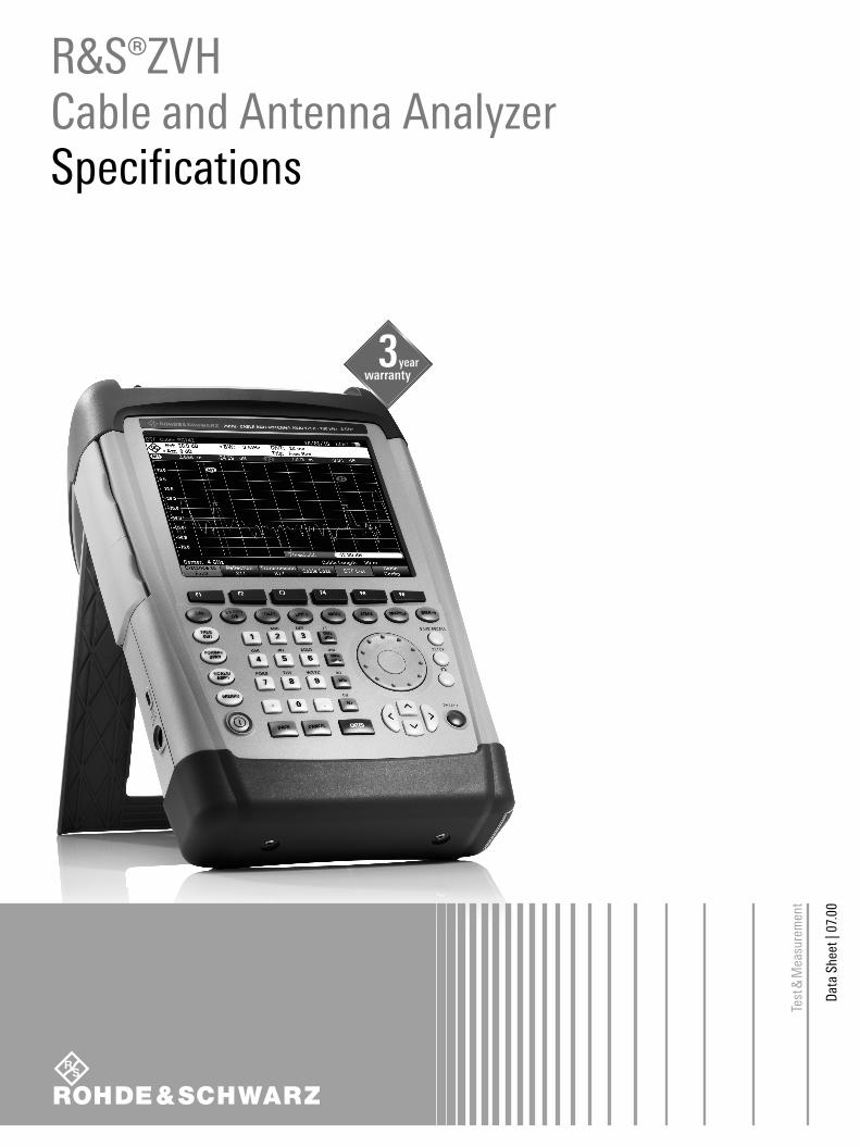
Specifications with limits
Represent warranted product performance by means of a range of values for the specified parameter. These specifications are
marked with limiting symbols such as <, ≤, >, ≥, ±, or descriptions such as maximum, limit of, minimum. Compliance is ensured by
testing or is derived from the design. Test limits are narrowed by guard bands to take into account measurement uncertainties, drift
and aging, if applicable.
Specifications without limits
Represent warranted product performance for the specified parameter. These specifications are not specially marked and represent
values with no or negligible deviations from the given value (e.g. dimensions or resolution of a setting parameter). Compliance is
ensured by design.
Typical data (typ.)
Characterizes product performance by means of representative information for the given parameter. When marked with <, > or as a
range, it represents the performance met by approximately 80 % of the instruments at production time. Otherwise, it represents the
mean value.
Nominal values (nom.)
Characterize product performance by means of a representative value for the given parameter (e.g. nominal impedance). In contrast to
typical data, a statistical evaluation does not take place and the parameter is not tested during production.
Measured values (meas.)
Characterize expected product performance by means of measurement results gained from individual samples.
Uncertainties
Represent limits of measurement uncertainty for a given measurand. Uncertainty is defined with a coverage factor of 2 and has been
calculated in line with the rules of the Guide to the Expression of Uncertainty in Measurement (GUM), taking into account
environmental conditions, aging, wear and tear.
Device settings and GUI parameters are indicated as follows: “parameter: value”.
Typical data as well as nominal and measured values are not warranted by Rohde & Schwarz.
Version 07.00, June 2016
4 Rohde & Schwarz R&S®ZVH Cable and Antenna Analyzer
Specifications
Frequency Frequency range R&S®ZVH4 100 kHz to 3.6 GHz
R&S®ZVH8 100 kHz to 8 GHz
Frequency resolution 1 Hz
Reference frequency, internal
Total reference accuracy ±(time since last adjustment × aging rate)
+ temperature drift + calibration accuracy
Aging per year ±1 × 10⁻⁶
Temperature drift 0 °C to +50 °C 1 ±1 × 10⁻⁶
Achievable initial calibration accuracy ±5 × 10⁻⁷
Reference frequency, with R&S®HA-Z240 GPS receiver option
Frequency accuracy GPS on, ≥ 1 min after satellite lock ±2.5 × 10⁻⁸
up to 30 min after losing satellite lock ±5 × 10⁻⁸
Reference frequency, with R&S®FSH-Z114 precision frequency reference option
Aging per year 3.6 × 10⁻⁹
Temperature drift 0 °C to +50 °C 4 × 10⁻¹⁰
Achievable initial calibration accuracy 1 × 10⁻⁹
Total reference uncertainty R&S®FSH-Z114 connected
≥ 30 s after oscillator lock (time since last adjustment × aging rate) +
temperature drift + 3 × calibration accuracy
(nominal)
≥ 2 min after oscillator lock (time since last adjustment × aging rate) +
temperature drift + calibration accuracy
Frequency readout
Marker resolution 0.1 Hz
Accuracy ±(marker frequency × reference accuracy
+ 10 % × measurement bandwidth +
½ ((fstop – fstart) / (data points – 1) + 1 Hz)
1 For serial number < 115000: +30 °C to +50 °C: 3 × 10⁻⁶.
Version 07.00, June 2016
Rohde & Schwarz R&S®ZVH Cable and Antenna Analyzer 5
Measurements Individual measurements reflection (S11, S22)
with R&S® ZVH-K39 option transmission (S21, S12)
1-port cable loss
distance-to-fault
Measurement wizard
Guides the user through a sequence of individual measurements. Uses the R&S®ZVHView PC software to configure the
measurement sequence including hints displayed on the screen. R&S®ZVHView is also used to combine the measurement results
into user-configurable reports.
Measurement setup
Port output power controlled via tracking generator
attenuation
0 dBm to –40 dBm (nom.), in 1 dB steps
Receive path RF attenuation 0 dB to 30 dB in 5 dB steps
Data points selectable 101, 201, 401, 601, 631, 801, 1001, 1201
Measurement bandwidth range 100 Hz to 100 kHz in 1/3 sequence
Trace modes clear/write, average, interference
suppression
DC bias
DC source selectable internal or external
Output port selectable port 1 or 2
Output voltage mode: internal +12 V to +32 V in 1 V steps
Maximum output power mode: internal
operated with battery 4 W
operated with AC mains 10 W
Maximum continuous output current mode: internal 500 mA
Trigger
Trigger source free run, external rise, external fall
External trigger level TTL level
Reflection measurement S11, S22
Result formats magnitude, VSWR
Magnitude
Range 1/2/5/10/20/50/100/120/150 dB,
linear 100 %
Resolution 0.01 dB
VSWR
Range selectable 1 to 1.5, 2, 6, 11, 21 or 71
Corrected directivity 100 kHz ≤ f ≤ 3 GHz > 43 dB (nom.)
3 GHz < f ≤ 6 GHz > 37 dB (nom.)
6 GHz < f ≤ 8 GHz > 31 dB (nom.)
Corrected test port match 100 kHz ≤ f ≤ 3 GHz > 40 dB (nom.)
3 GHz < f ≤ 6 GHz > 37 dB (nom.)
6 GHz < f ≤ 8 GHz > 30 dB (nom.)
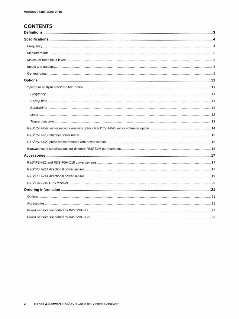
Measurement uncertainty see figure “Uncertainty of reflection
measurement” on page 7
Transmission measurement S21, S12 (with R&S®ZVH-K39 option)
Result format magnitude
Measurement range –120 dB to +80 dB
Display range selectable 1/2/5/10/20/50/100/120/150 dB,
linear 100 %
Resolution 0.01 dB
Dynamic range RF attenuation = 5 dB, tracking generator level = –10 dBm, RBW = 1 kHz
100 kHz ≤ f < 300 kHz > 50 dB (nom.)
300 kHz ≤ f < 2.5 GHz > 80 dB, 100 dB (typ.)
2.5 GHz ≤ f < 6 GHz > 70 dB , 90 dB (typ.)
6 GHz ≤ f < 8 GHz > 50 dB (nom.)
Test port match as specified for test port input/output
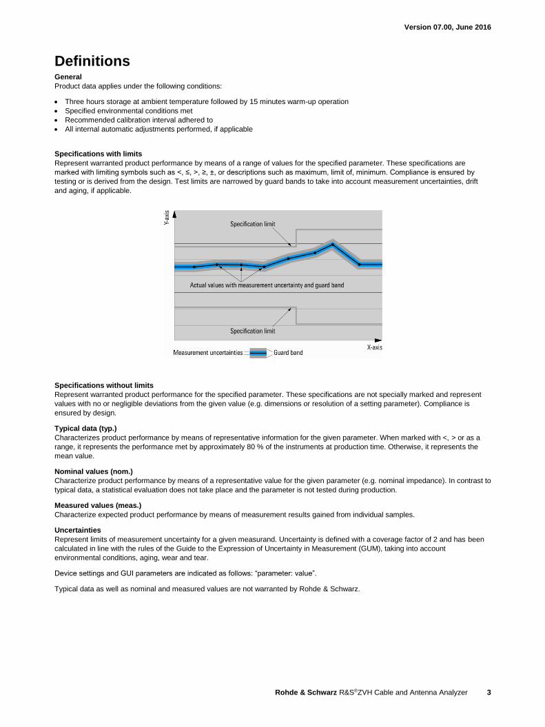
Measurement uncertainty calibration method = full two port high
accuracy
see figure “Transmission magnitude
uncertainty” on page 7
Version 07.00, June 2016
6 Rohde & Schwarz R&S®ZVH Cable and Antenna Analyzer
1-port cable loss measurement
Result format magnitude
Range selectable 1/2/5/10/20/50/100/120/150 dB
Resolution 0.01 dB
Distance-to-fault analysis
Result formats return loss,
VSWR (average and maximum indication)
Return loss
Range 1/2/5/10/20/50/100/120/150 dB,
linear 100 %
Resolution 0.01 dB
VSWR
Range selectable 1 to 1.5, 2, 6, 11, 21 or 71
Fault resolution in meters (1.5 × 10⁸ × velocity factor/span)
Maximum cable length depending on cable loss 1500 m (nom.)
Immunity to interference
Maximum permissible spurious signal measurement = reflection (S11)/1-port cable loss/distance-to-fault analysis
RF attenuation = 5 dB +10 dBm (nom.)
RF attenuation = 30 dB +17 dBm (nom.)
Version 07.00, June 2016
Rohde & Schwarz R&S®ZVH Cable and Antenna Analyzer 7
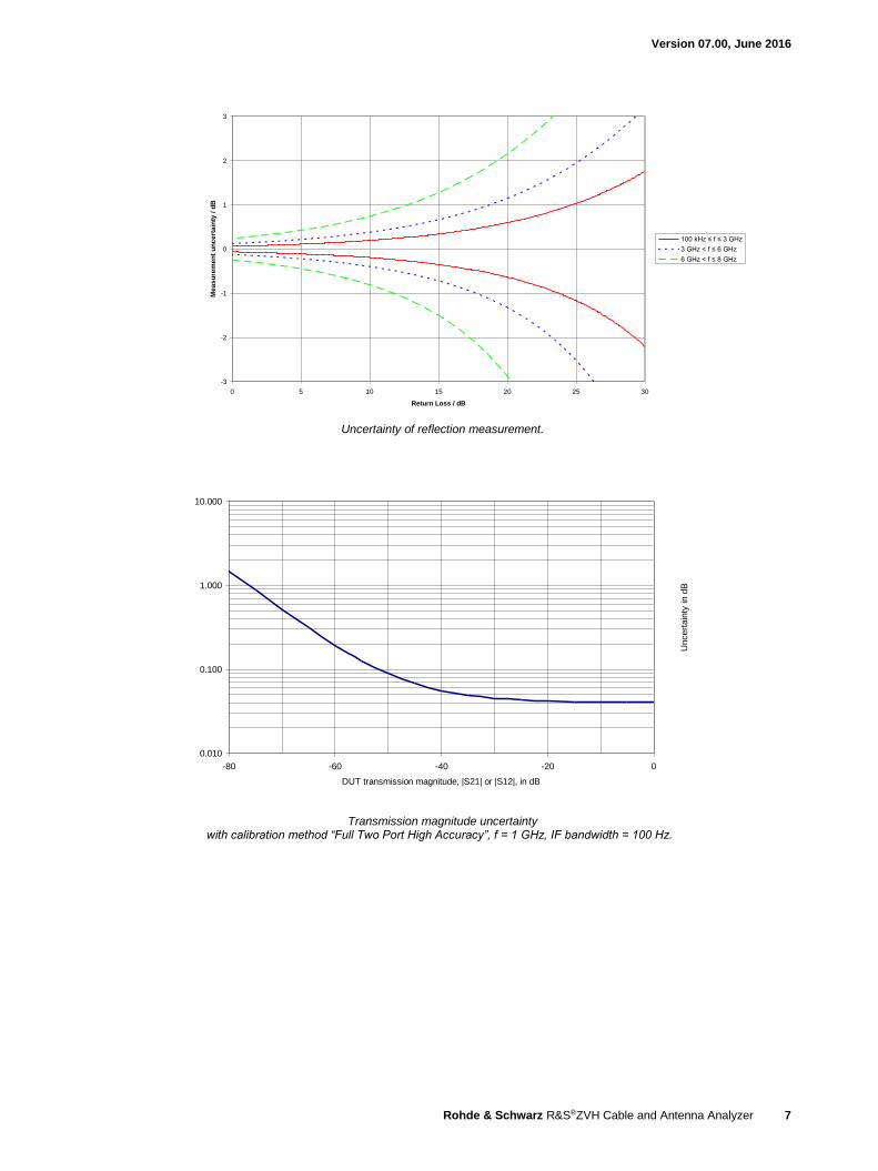
Uncertainty of reflection measurement
-3
-2
-1
0
1
2
3
0 5 10 15 20 25 30
Return Loss / dB
Me
as
ure
me
nt
un
ce
rta
inty
/ d
B
100 kHz ≤ f ≤ 3 GHz
3 GHz < f ≤ 6 GHz
6 GHz < f ≤ 8 GHz
1Uncertainty of reflection measurement.
Transmission magnitude uncertaintywith calibration method "Full Two Port High Accuracy", f=1GHz, IF bandwidth=100Hz
0.010
0.100
1.000
10.000
-80 -60 -40 -20 0
DUT transmission magnitude, |S21| or |S12|, in dB
Uncert
ain
ty in d
B
2Transmission magnitude uncertainty with calibration method “Full Two Port High Accuracy”, f = 1 GHz, IF bandwidth = 100 Hz.
Version 07.00, June 2016
8 Rohde & Schwarz R&S®ZVH Cable and Antenna Analyzer
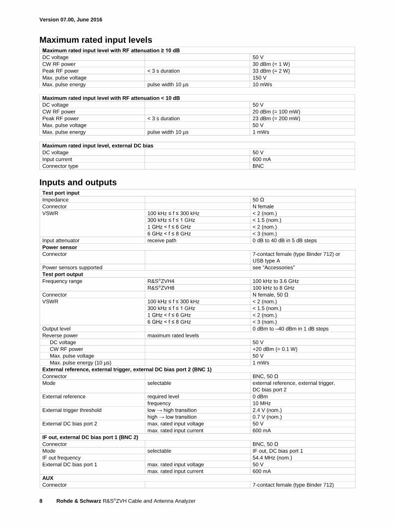
Maximum rated input levels Maximum rated input level with RF attenuation ≥ 10 dB
DC voltage 50 V
CW RF power 30 dBm (= 1 W)
Peak RF power < 3 s duration 33 dBm (= 2 W)
Max. pulse voltage 150 V
Max. pulse energy pulse width 10 µs 10 mWs
Maximum rated input level with RF attenuation < 10 dB
DC voltage 50 V
CW RF power 20 dBm (= 100 mW)
Peak RF power < 3 s duration 23 dBm (= 200 mW)
Max. pulse voltage 50 V
Max. pulse energy pulse width 10 µs 1 mWs
Maximum rated input level, external DC bias
DC voltage 50 V
Input current 600 mA
Connector type BNC
Inputs and outputs Test port input
Impedance 50 Ω
Connector N female
VSWR 100 kHz ≤ f ≤ 300 kHz < 2 (nom.)
300 kHz ≤ f ≤ 1 GHz < 1.5 (nom.)
1 GHz < f ≤ 6 GHz < 2 (nom.)
6 GHz < f ≤ 8 GHz < 3 (nom.)
Input attenuator receive path 0 dB to 40 dB in 5 dB steps
Power sensor
Connector 7-contact female (type Binder 712) or
USB type A
Power sensors supported see “Accessories”
Test port output
Frequency range R&S®ZVH4 100 kHz to 3.6 GHz
R&S®ZVH8 100 kHz to 8 GHz
Connector N female, 50 Ω
VSWR 100 kHz ≤ f ≤ 300 kHz < 2 (nom.)
300 kHz ≤ f ≤ 1 GHz < 1.5 (nom.)
1 GHz < f ≤ 6 GHz < 2 (nom.)
6 GHz < f ≤ 8 GHz < 3 (nom.)
Output level 0 dBm to –40 dBm in 1 dB steps
Reverse power maximum rated levels
DC voltage 50 V
CW RF power +20 dBm (= 0.1 W)
Max. pulse voltage 50 V
Max. pulse energy (10 µs) 1 mWs
External reference, external trigger, external DC bias port 2 (BNC 1)
Connector BNC, 50 Ω
Mode selectable external reference, external trigger,
DC bias port 2
External reference required level 0 dBm
frequency 10 MHz
External trigger threshold low → high transition 2.4 V (nom.)
high → low transition 0.7 V (nom.)
External DC bias port 2 max. rated input voltage 50 V
max. rated input current 600 mA
IF out, external DC bias port 1 (BNC 2)
Connector BNC, 50 Ω
Mode selectable IF out, DC bias port 1
IF out frequency 54.4 MHz (nom.)
External DC bias port 1 max. rated input voltage 50 V
max. rated input current 600 mA
AUX
Connector 7-contact female (type Binder 712)
Version 07.00, June 2016
Rohde & Schwarz R&S®ZVH Cable and Antenna Analyzer 9
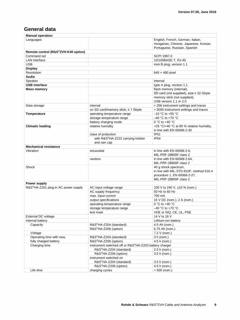
General data Manual operation
Languages English, French, German, Italian,
Hungarian, Chinese, Japanese, Korean,
Portuguese, Russian, Spanish
Remote control (R&S®ZVH-K40 option)
Command set SCPI 1997.0
LAN interface 10/100BASE-T, RJ-45
USB mini B plug, version 1.1
Display
Resolution 640 × 480 pixel
Audio
Speaker internal
USB interface type A plug, version 1.1
Mass memory flash memory (internal),
SD card (not supplied), size ≤ 32 Gbyte
memory stick (not supplied),
USB version 1.1 or 2.0
Data storage internal > 256 instrument settings and traces
on SD card/memory stick, ≥ 1 Gbyte > 5000 instrument settings and traces
Temperature operating temperature range –10 °C to +55 °C
storage temperature range –40 °C to +70 °C
battery charging mode 0 °C to +40 °C
Climatic loading relative humidity +25 °C/+40 °C at 85 % relative humidity,
in line with EN 60068-2-30
class of protection IP51
with R&S®HA-Z222 carrying holster
and rain cap
IP54
Mechanical resistance
Vibration sinusoidal in line with EN 60068-2-6,
MIL-PRF-28800F class 2
random in line with EN 60068-2-64,
MIL-PRF-28800F class 2
Shock 40 g shock spectrum,
in line with MIL-STD-810F, method 516.4
procedure 1, EN 60068-2-27,
MIL-PRF-28800F class 2
Power supply
R&S®HA-Z201 plug-in AC power supply AC input voltage range 100 V to 240 V, ±10 % (nom.)
AC supply frequency 50 Hz to 60 Hz
max. input current 700 mA
output specifications 15 V DC (nom.), 2 A (nom.)
operating temperature range 0 °C to +40 °C
storage temperature range –40 °C to +70 °C
test mark VDE or SIQ, CE, UL, PSE
External DC voltage 14 V to 16 V
Internal battery Lithium-ion battery
Capacity R&S®HA-Z204 (standard) 4.5 Ah (nom.)
R&S®HA-Z206 (option) 6.75 Ah (nom.)
Voltage 7.2 V (nom.)
Operating time with new,
fully charged battery
R&S®HA-Z204 (standard) 3 h (nom.)
R&S®HA-Z206 (option) 4.5 h (nom.)
Charging time instrument switched off or R&S®HA-Z203 battery charger
R&S®HA-Z204 (standard) 2.5 h (nom.)
R&S®HA-Z206 (option) 3.5 h (nom.)
instrument switched on
R&S®HA-Z204 (standard) 3.5 h (nom.)
R&S®HA-Z206 (option) 4.5 h (nom.)
Life time charging cycles > 500 (nom.)
Version 07.00, June 2016
10 Rohde & Schwarz R&S®ZVH Cable and Antenna Analyzer
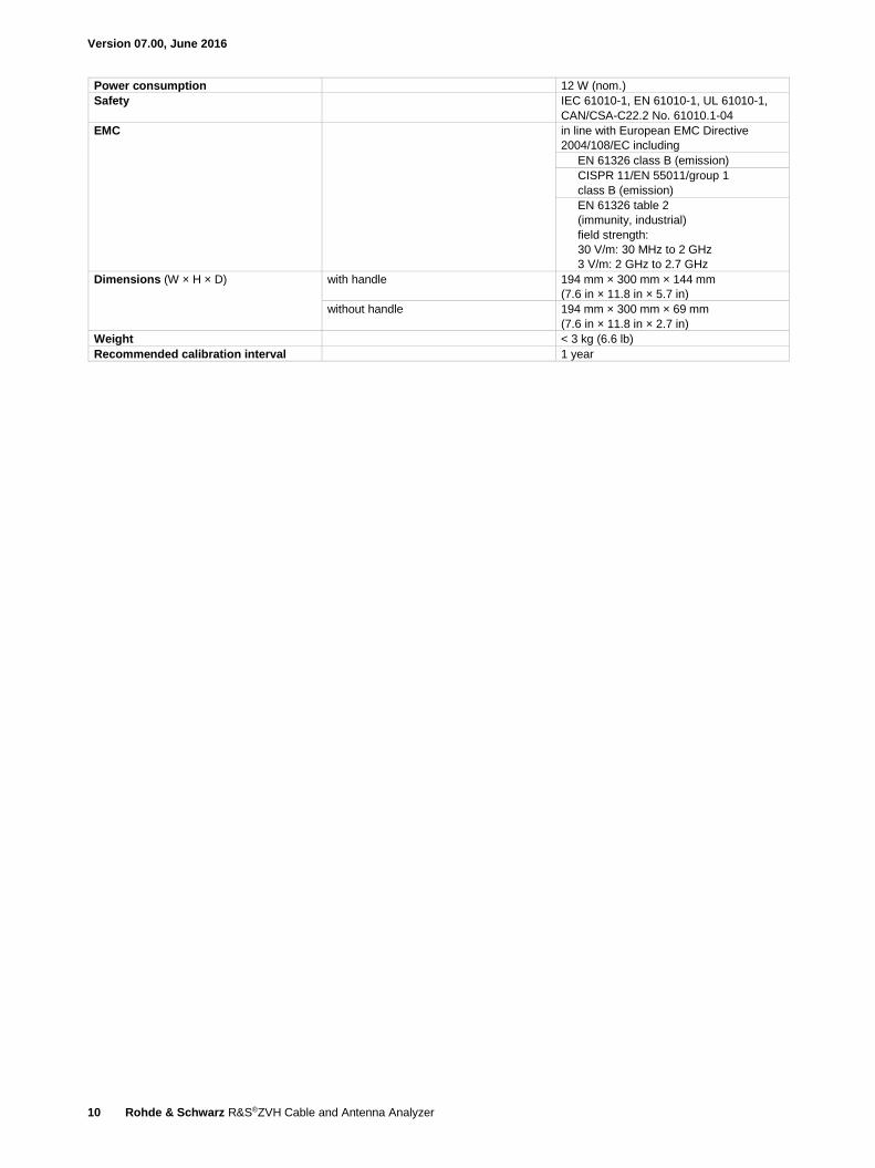
Power consumption 12 W (nom.)
Safety IEC 61010-1, EN 61010-1, UL 61010-1,
CAN/CSA-C22.2 No. 61010.1-04
EMC in line with European EMC Directive
2004/108/EC including
EN 61326 class B (emission)
CISPR 11/EN 55011/group 1
class B (emission)
EN 61326 table 2
(immunity, industrial)
field strength:
30 V/m: 30 MHz to 2 GHz
3 V/m: 2 GHz to 2.7 GHz
Dimensions (W × H × D) with handle 194 mm × 300 mm × 144 mm
(7.6 in × 11.8 in × 5.7 in)
without handle 194 mm × 300 mm × 69 mm
(7.6 in × 11.8 in × 2.7 in)
Weight < 3 kg (6.6 lb)
Recommended calibration interval 1 year
Version 07.00, June 2016
Rohde & Schwarz R&S®ZVH Cable and Antenna Analyzer 11
Options
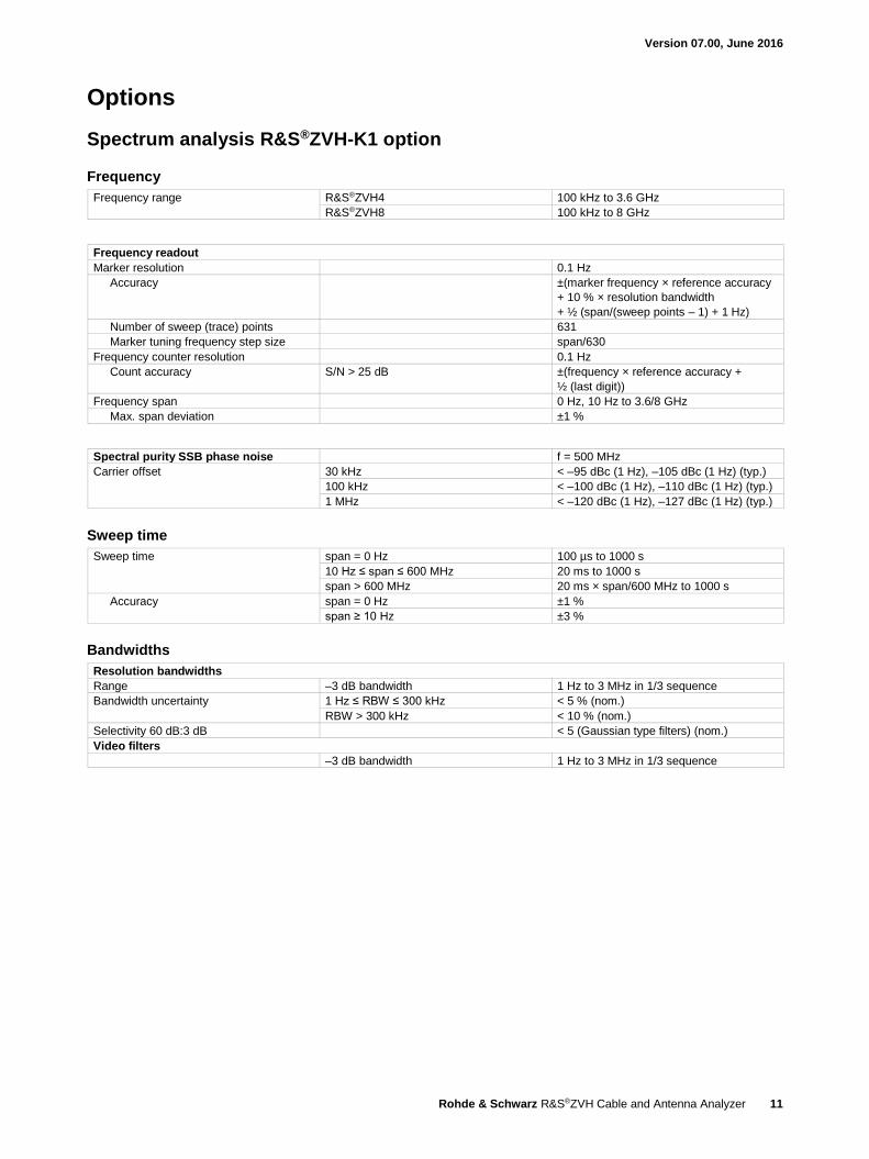
Spectrum analysis R&S®ZVH-K1 option
Frequency
Frequency range R&S®ZVH4 100 kHz to 3.6 GHz
R&S®ZVH8 100 kHz to 8 GHz
Frequency readout
Marker resolution 0.1 Hz
Accuracy ±(marker frequency × reference accuracy
+ 10 % × resolution bandwidth
+ ½ (span/(sweep points – 1) + 1 Hz)
Number of sweep (trace) points 631
Marker tuning frequency step size span/630
Frequency counter resolution 0.1 Hz
Count accuracy S/N > 25 dB ±(frequency × reference accuracy +
½ (last digit))
Frequency span 0 Hz, 10 Hz to 3.6/8 GHz
Max. span deviation ±1 %
Spectral purity SSB phase noise f = 500 MHz
Carrier offset 30 kHz < –95 dBc (1 Hz), –105 dBc (1 Hz) (typ.)
100 kHz < –100 dBc (1 Hz), –110 dBc (1 Hz) (typ.)
1 MHz < –120 dBc (1 Hz), –127 dBc (1 Hz) (typ.)
Sweep time
Sweep time span = 0 Hz 100 µs to 1000 s
10 Hz ≤ span ≤ 600 MHz 20 ms to 1000 s
span > 600 MHz 20 ms × span/600 MHz to 1000 s
Accuracy span = 0 Hz ±1 %
span ≥ 10 Hz ±3 %
Bandwidths
Resolution bandwidths
Range –3 dB bandwidth 1 Hz to 3 MHz in 1/3 sequence
Bandwidth uncertainty 1 Hz ≤ RBW ≤ 300 kHz < 5 % (nom.)
RBW > 300 kHz < 10 % (nom.)
Selectivity 60 dB:3 dB < 5 (Gaussian type filters) (nom.)
Video filters
–3 dB bandwidth 1 Hz to 3 MHz in 1/3 sequence
Version 07.00, June 2016
12 Rohde & Schwarz R&S®ZVH Cable and Antenna Analyzer
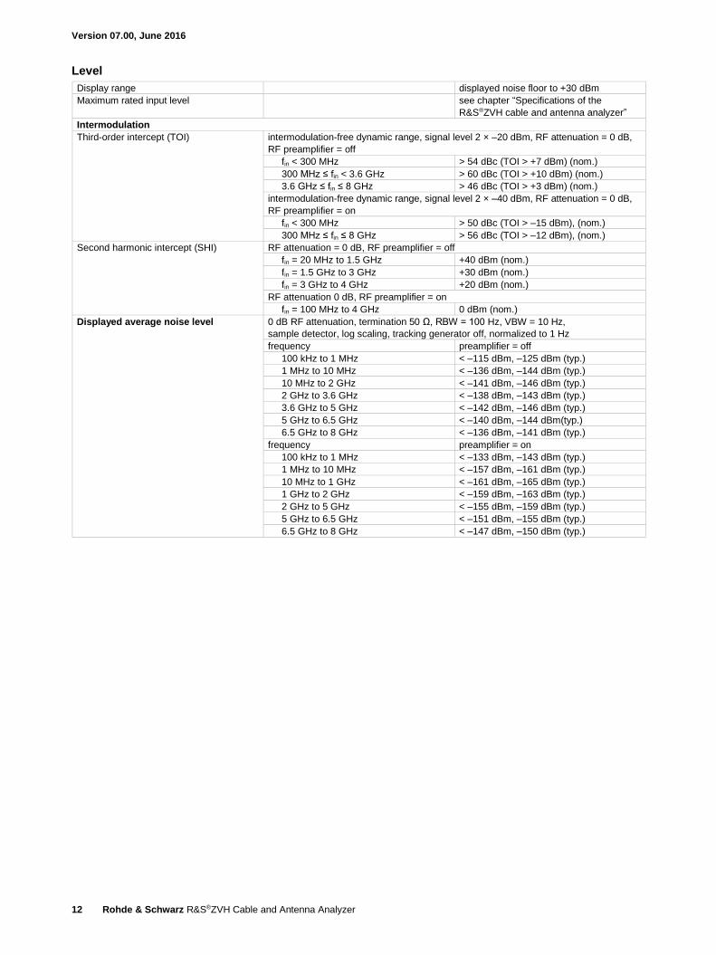
Level
Display range displayed noise floor to +30 dBm
Maximum rated input level see chapter “Specifications of the
R&S®ZVH cable and antenna analyzer”
Intermodulation
Third-order intercept (TOI) intermodulation-free dynamic range, signal level 2 × –20 dBm, RF attenuation = 0 dB,
RF preamplifier = off
fin < 300 MHz > 54 dBc (TOI > +7 dBm) (nom.)
300 MHz ≤ fin < 3.6 GHz > 60 dBc (TOI > +10 dBm) (nom.)
3.6 GHz ≤ fin ≤ 8 GHz > 46 dBc (TOI > +3 dBm) (nom.)
intermodulation-free dynamic range, signal level 2 × –40 dBm, RF attenuation = 0 dB,
RF preamplifier = on
fin < 300 MHz > 50 dBc (TOI > –15 dBm), (nom.)
300 MHz ≤ fin ≤ 8 GHz > 56 dBc (TOI > –12 dBm), (nom.)
Second harmonic intercept (SHI) RF attenuation = 0 dB, RF preamplifier = off
fin = 20 MHz to 1.5 GHz +40 dBm (nom.)
fin = 1.5 GHz to 3 GHz +30 dBm (nom.)
fin = 3 GHz to 4 GHz +20 dBm (nom.)
RF attenuation 0 dB, RF preamplifier = on
fin = 100 MHz to 4 GHz 0 dBm (nom.)
Displayed average noise level 0 dB RF attenuation, termination 50 Ω, RBW = 100 Hz, VBW = 10 Hz,
sample detector, log scaling, tracking generator off, normalized to 1 Hz
frequency preamplifier = off
100 kHz to 1 MHz < –115 dBm, –125 dBm (typ.)
1 MHz to 10 MHz < –136 dBm, –144 dBm (typ.)
10 MHz to 2 GHz < –141 dBm, –146 dBm (typ.)
2 GHz to 3.6 GHz < –138 dBm, –143 dBm (typ.)
3.6 GHz to 5 GHz < –142 dBm, –146 dBm (typ.)
5 GHz to 6.5 GHz < –140 dBm, –144 dBm(typ.)
6.5 GHz to 8 GHz < –136 dBm, –141 dBm (typ.)
frequency preamplifier = on
100 kHz to 1 MHz < –133 dBm, –143 dBm (typ.)
1 MHz to 10 MHz < –157 dBm, –161 dBm (typ.)
10 MHz to 1 GHz < –161 dBm, –165 dBm (typ.)
1 GHz to 2 GHz < –159 dBm, –163 dBm (typ.)
2 GHz to 5 GHz < –155 dBm, –159 dBm (typ.)
5 GHz to 6.5 GHz < –151 dBm, –155 dBm (typ.)
6.5 GHz to 8 GHz < –147 dBm, –150 dBm (typ.)
Version 07.00, June 2016
Rohde & Schwarz R&S®ZVH Cable and Antenna Analyzer 13
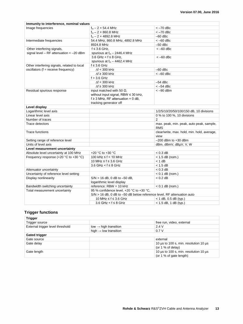
Immunity to interference, nominal values
Image frequencies fin – 2 × 54.4 MHz < –70 dBc
fin – 2 × 860.8 MHz < –70 dBc
fin – 2 × 4892.8 MHz –60 dBc
Intermediate frequencies 54.4 MHz, 860.8 MHz, 4892.8 MHz < –60 dBc
8924.8 MHz –50 dBc
Other interfering signals,
signal level – RF attenuation < –20 dBm
f ≤ 3.6 GHz,
spurious at fin – 2446.4 MHz
< –60 dBc
3.6 GHz < f ≤ 8 GHz,
spurious at fin – 4462.4 MHz
< –60 dBc
Other interfering signals, related to local
oscillators (f = receive frequency)
f ≤ 3.6 GHz
∆f < 300 kHz –60 dBc
∆f ≥ 300 kHz < –60 dBc
f > 3.6 GHz
∆f < 300 kHz –54 dBc
∆f ≥ 300 kHz < –54 dBc
Residual spurious response input matched with 50 Ω,
without input signal, RBW ≤ 30 kHz,
f ≥ 3 MHz, RF attenuation = 0 dB,
tracking generator off
< –90 dBm
Level display
Logarithmic level axis 1/2/5/10/20/50/100/150 dB, 10 divisions
Linear level axis 0 % to 100 %, 10 divisions
Number of traces 2
Trace detectors max. peak, min. peak, auto peak, sample,
RMS
Trace functions clear/write, max. hold, min. hold, average,
view
Setting range of reference level –200 dBm to +30 dBm
Units of level axis dBm, dBmV, dBµV, V, W
Level measurement uncertainty
Absolute level uncertainty at 100 MHz +20 °C to +30 °C < 0.3 dB
Frequency response (+20 °C to +30 °C) 100 kHz ≤ f < 10 MHz < 1.5 dB (nom.)
10 MHz ≤ f ≤ 3.6 GHz < 1 dB
3.6 GHz < f ≤ 8 GHz < 1.5 dB
Attenuator uncertainty < 0.3 dB
Uncertainty of reference level setting < 0.1 dB (nom.)
Display nonlinearity S/N > 16 dB, 0 dB to –50 dB,
logarithmic level display
< 0.2 dB
Bandwidth switching uncertainty reference: RBW = 10 kHz < 0.1 dB (nom.)
Total measurement uncertainty 95 % confidence level, +20 °C to +30 °C,
S/N > 16 dB, 0 dB to –50 dB below reference level, RF attenuation auto
10 MHz ≤ f ≤ 3.6 GHz < 1 dB, 0.5 dB (typ.)
3.6 GHz < f ≤ 8 GHz < 1.5 dB, 1 dB (typ.)
Trigger functions
Trigger
Trigger source free run, video, external
External trigger level threshold low → high transition 2.4 V
high → low transition 0.7 V
Gated trigger
Gate source external
Gate delay 10 µs to 100 s, min. resolution 10 µs
(or 1 % of delay)
Gate length 10 µs to 100 s, min. resolution 10 µs
(or 1 % of gate length)
Version 07.00, June 2016
14 Rohde & Schwarz R&S®ZVH Cable and Antenna Analyzer
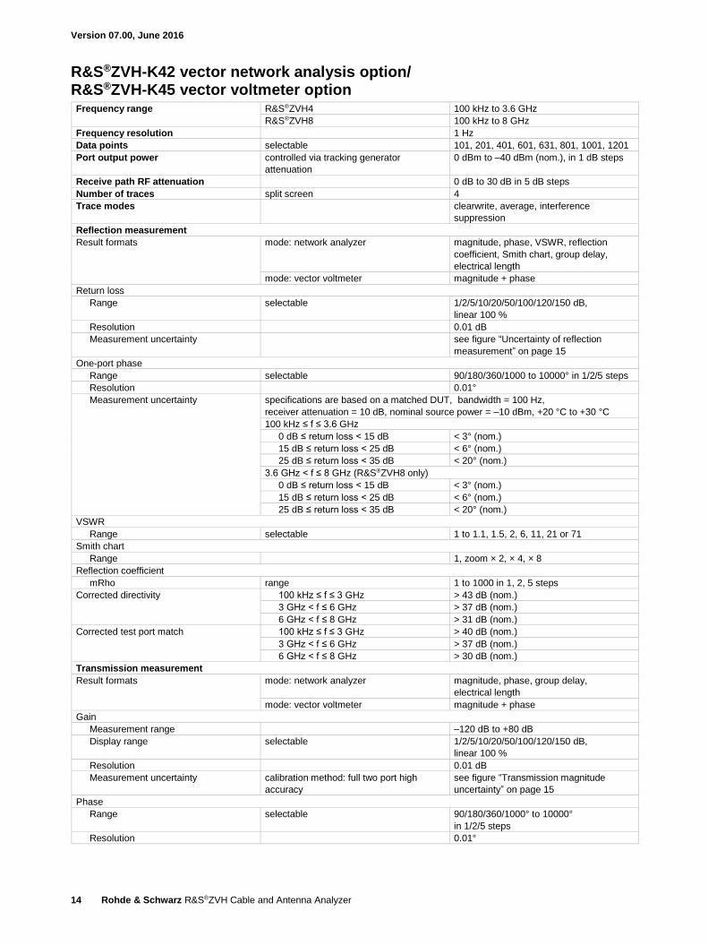
R&S®ZVH-K42 vector network analysis option/ R&S®ZVH-K45 vector voltmeter option Frequency range R&S®ZVH4 100 kHz to 3.6 GHz
R&S®ZVH8 100 kHz to 8 GHz
Frequency resolution 1 Hz
Data points selectable 101, 201, 401, 601, 631, 801, 1001, 1201
Port output power controlled via tracking generator
attenuation
0 dBm to –40 dBm (nom.), in 1 dB steps
Receive path RF attenuation 0 dB to 30 dB in 5 dB steps
Number of traces split screen 4
Trace modes clearwrite, average, interference
suppression
Reflection measurement
Result formats mode: network analyzer magnitude, phase, VSWR, reflection
coefficient, Smith chart, group delay,
electrical length
mode: vector voltmeter magnitude + phase
Return loss
Range selectable 1/2/5/10/20/50/100/120/150 dB,
linear 100 %
Resolution 0.01 dB
Measurement uncertainty see figure “Uncertainty of reflection
measurement” on page 15
One-port phase
Range selectable 90/180/360/1000 to 10000° in 1/2/5 steps
Resolution 0.01°
Measurement uncertainty specifications are based on a matched DUT, bandwidth = 100 Hz,
receiver attenuation = 10 dB, nominal source power = –10 dBm, +20 °C to +30 °C
100 kHz ≤ f ≤ 3.6 GHz
0 dB ≤ return loss < 15 dB < 3° (nom.)
15 dB ≤ return loss < 25 dB < 6° (nom.)
25 dB ≤ return loss < 35 dB < 20° (nom.)
3.6 GHz < f ≤ 8 GHz (R&S®ZVH8 only)
0 dB ≤ return loss < 15 dB < 3° (nom.)
15 dB ≤ return loss < 25 dB < 6° (nom.)
25 dB ≤ return loss < 35 dB < 20° (nom.)
VSWR
Range selectable 1 to 1.1, 1.5, 2, 6, 11, 21 or 71
Smith chart
Range 1, zoom × 2, × 4, × 8
Reflection coefficient
mRho range 1 to 1000 in 1, 2, 5 steps
Corrected directivity 100 kHz ≤ f ≤ 3 GHz > 43 dB (nom.)
3 GHz < f ≤ 6 GHz > 37 dB (nom.)
6 GHz < f ≤ 8 GHz > 31 dB (nom.)
Corrected test port match 100 kHz ≤ f ≤ 3 GHz > 40 dB (nom.)
3 GHz < f ≤ 6 GHz > 37 dB (nom.)
6 GHz < f ≤ 8 GHz > 30 dB (nom.)
Transmission measurement
Result formats mode: network analyzer magnitude, phase, group delay,
electrical length
mode: vector voltmeter magnitude + phase
Gain
Measurement range –120 dB to +80 dB
Display range selectable 1/2/5/10/20/50/100/120/150 dB,
linear 100 %
Resolution 0.01 dB
Measurement uncertainty calibration method: full two port high
accuracy
see figure “Transmission magnitude
uncertainty” on page 15
Phase
Range selectable 90/180/360/1000° to 10000°
in 1/2/5 steps
Resolution 0.01°
Version 07.00, June 2016
Rohde & Schwarz R&S®ZVH Cable and Antenna Analyzer 15
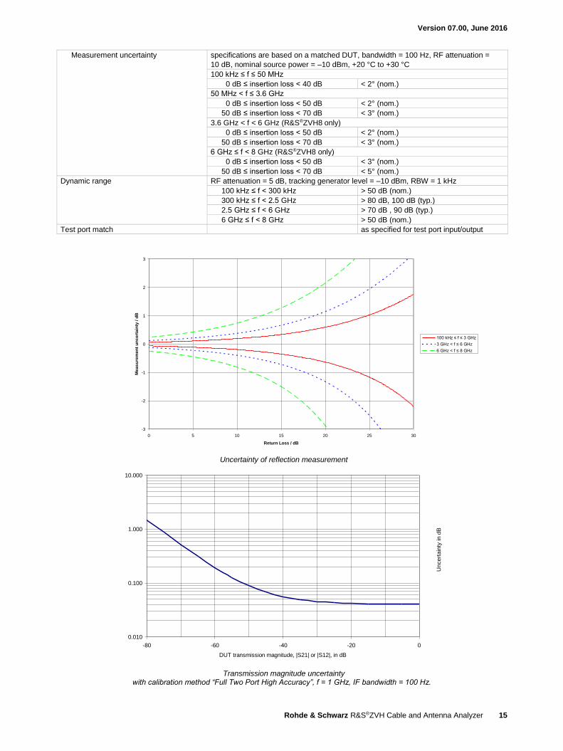
Measurement uncertainty specifications are based on a matched DUT, bandwidth = 100 Hz, RF attenuation =
10 dB, nominal source power = –10 dBm, +20 °C to +30 °C
100 kHz ≤ f ≤ 50 MHz
0 dB ≤ insertion loss < 40 dB < 2° (nom.)
50 MHz < f ≤ 3.6 GHz
0 dB ≤ insertion loss < 50 dB < 2° (nom.)
50 dB ≤ insertion loss < 70 dB < 3° (nom.)
3.6 GHz < f < 6 GHz (R&S®ZVH8 only)
0 dB ≤ insertion loss < 50 dB < 2° (nom.)
50 dB ≤ insertion loss < 70 dB < 3° (nom.)
6 GHz ≤ f < 8 GHz (R&S®ZVH8 only)
0 dB ≤ insertion loss < 50 dB < 3° (nom.)
50 dB ≤ insertion loss < 70 dB < 5° (nom.)
Dynamic range RF attenuation = 5 dB, tracking generator level = –10 dBm, RBW = 1 kHz
100 kHz ≤ f < 300 kHz > 50 dB (nom.)
300 kHz ≤ f < 2.5 GHz > 80 dB, 100 dB (typ.)
2.5 GHz ≤ f < 6 GHz > 70 dB , 90 dB (typ.)
6 GHz ≤ f < 8 GHz > 50 dB (nom.)
Test port match as specified for test port input/output
Uncertainty of reflection measurement
-3
-2
-1
0
1
2
3
0 5 10 15 20 25 30
Return Loss / dB
Me
as
ure
me
nt
un
ce
rta
inty
/ d
B
100 kHz ≤ f ≤ 3 GHz
3 GHz < f ≤ 6 GHz
6 GHz < f ≤ 8 GHz
3Uncertainty of reflection measurement Transmission magnitude uncertaintywith calibration method "Full Two Port High Accuracy", f=1GHz, IF bandwidth=100Hz
0.010
0.100
1.000
10.000
-80 -60 -40 -20 0
DUT transmission magnitude, |S21| or |S12|, in dB
Uncert
ain
ty in d
B
4Transmission magnitude uncertainty with calibration method “Full Two Port High Accuracy”, f = 1 GHz, IF bandwidth = 100 Hz.
Version 07.00, June 2016
16 Rohde & Schwarz R&S®ZVH Cable and Antenna Analyzer
R&S®ZVH-K19 channel power meter Frequency range R&S®ZVH4 100 kHz to 3.6 GHz
R&S®ZVH8 100 kHz to 8 GHz
Channel bandwidth 100 kHz to 1 GHz
Amplitude offset, dB relative, zeroing
Unit dBm, W
Limits on/off, upper limit, lower limit, beep on fail
Measurement range –120 dBm to +30 dBm
Level measurement uncertainty
Absolute level uncertainty at 100 MHz +20 °C to +30 °C < 0.3 dB
Frequency response (+20 °C to +30 °C) 100 kHz ≤ f < 10 MHz < 1.5 dB (nom.)
10 MHz ≤ f ≤ 3.6 GHz < 1 dB
3.6 GHz < f ≤ 8 GHz < 1.5 dB
Measurement port port 1
R&S®ZVH-K29 pulse measurements with power sensor In combination with one of the power sensors R&S®NRP-Z81/-Z85/-Z86, the R&S®ZVH4/8 supports measurements on pulsed
signals 2. The achievable RF performance is documented in the data sheet specifications of the R&S®NRP-Z81/-Z85/-Z86 power
sensors. The list below shows which measurements are supported by the R&S®ZVH-K29.
Measurements R&S®FSH-K29
Pulse power parameters
Peak power
Pulse top power
Average power
Base power
Minimum power
Positive overshoot
Negative overshoot
Pulse timing parameters
Pulse duration
Pulse period
Pulse start/stop time
Rise/fall time
Duty cycle
Equivalence of specifications for different R&S®ZVH part numbers The specifications for part number 1309.6800.74 are equivalent to part number 1309.6000.24
The specifications for part number 1309.6800.78 are equivalent to part number 1309.6000.28
2 The R&S®NRP-Z8x power sensors are supported by instruments with serial number ≥ 105000. The R&S®FSH-Z129 adapter cable is needed in
addition for R&S®ZVH4 with serial number < 115340 and for R&S®ZVH8 with serial number <115240.
Version 07.00, June 2016
Rohde & Schwarz R&S®ZVH Cable and Antenna Analyzer 17
Accessories
R&S®FSH-Z1 and R&S®FSH-Z18 power sensors Frequency range R&S®FSH-Z1 10 MHz to 8 GHz
R&S®FSH-Z18 10 MHz to 18 GHz
VSWR 10 MHz to 30 MHz < 1.15
30 MHz to 2.4 GHz < 1.13
2.4 GHz to 8 GHz < 1.20
8 GHz to 18 GHz < 1.25
Maximum input power average power 400 mW (+26 dBm)
peak power (< 10 µs, 1 % duty cycle) 1 W (+30 dBm)
Measurement range 200 pW to 200 mW
(–67 dBm to +23 dBm)
Signal weighting average power
Effect of harmonics < 0.5 % (0.02 dB)
at harmonic ratio of 20 dB
Effect of modulation < 1.5 % (0.07 dB)
for continuous digital modulation
Absolute measurement uncertainty sine signals, no zero offset
10 MHz to 8 GHz +15 °C to +35 °C < 2.3 % (0.10 dB)
0 °C to +50 °C < 4.2 % (0.18 dB)
8 GHz to 18 GHz +15 °C to +35 °C < 3.5 % (0.15 dB)
0 °C to +50 °C < 5.0 % (0.21 dB)
Zero offset after zeroing < 110 pW
Dimensions (W × H × D) 48 mm × 31 mm × 170 mm
(1.9 in × 1.2 in × 6.7 in)
connecting cable 1.5 m (59 in)
Weight < 0.3 kg (0.7 lb)
R&S®FSH-Z14 directional power sensor Frequency range 25 MHz to 1 GHz
Power measurement range 30 mW to 300 W
VSWR referenced to 50 Ω < 1.06
Power-handling capacity depending on temperature and matching
(see diagram on next page)
100 W to 1000 W
Insertion loss < 0.06 dB
Directivity > 30 dB
Average power
Power measurement range
CW, FM, PM, FSK, GMSK CF: ratio of peak envelope 30 mW to 300 W
Modulated signals power to average power 30 mW to 300 W/CF
Measurement uncertainty
25 MHz to 40 MHz sine signal 4.0 % of measured value (0.17 dB)
40 MHz to 1 GHz +18 °C to +28 °C, no zero offset 3.2 % of measured value (0.14 dB)
Zero offset after zeroing ±4 mW
Range of typical measurement error
with modulation
FM, PM, FSK, GMSK 0 % of measured value (0 dB)
AM (80 %) ±3 % of measured value (±0.13 dB)
two CW carriers with identical power ±2 % of measured value (±0.09 dB)
EDGE, TETRA ±0.5 % of measured value (±0.02 dB) 3
Temperature coefficient 25 MHz to 40 MHz 0.40 %/K (0.017 dB/K)
40 MHz to 1 GHz 0.25 %/K (0.011 dB/K)
3 If standard is selected on the R&S®ZVH.
Version 07.00, June 2016
18 Rohde & Schwarz R&S®ZVH Cable and Antenna Analyzer
Max. peak envelope power
Power measurement range
Video bandwidth 4 kHz 0.4 W to 300 W
200 kHz 1 W to 300 W
600 kHz 2 W to 300 W
Measurement uncertainty same as for average power plus effect of
peak hold circuit
+18 °C to +28 °C
Error limits of peak hold circuit for burst
signals
duty cycle ≥ 0.1 and repetition rate ≥ 100/s
video bandwidth 4 kHz ±(3 % of measured value + 0.05 W)
starting from a burst width of 200 µs
video bandwidth 200 kHz ±(3 % of measured value + 0.20 W)
starting from a burst width of 4 µs
video bandwidth 600 kHz ±(7 % of measured value + 0.40 W)
starting from a burst width of 2 µs
20/s ≤ repetition rate < 100/s plus ±(1.6 % of measured value + 0.15 W)
0.001 ≤ duty cycle < 0.1 plus ±0.10 W
Temperature coefficient 25 MHz to 40 MHz 0.50 %/K (0.022 dB/K)
40 MHz to 1 GHz 0.35 %/K (0.015 dB/K)
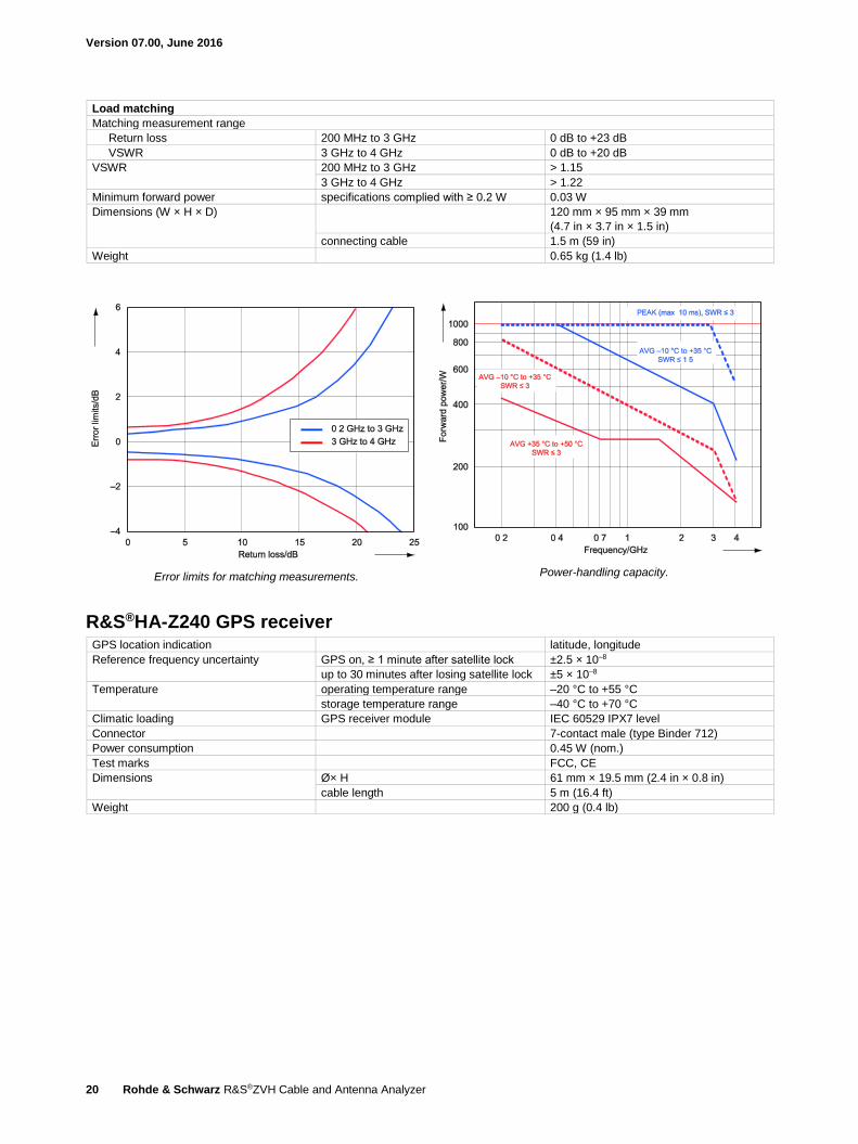
Load matching
Matching measurement range
Return loss 0 dB to 23 dB
VSWR > 1.15
Minimum forward power specifications complied with ≥ 0.4 W 0.06 W
Dimensions (W × H × D) 120 mm × 95 mm × 39 mm
(4.7 in × 3.7 in × 1.5 in)
connecting cable 1.5 m (59 in)
Weight 0.65 kg (1.4 lb)
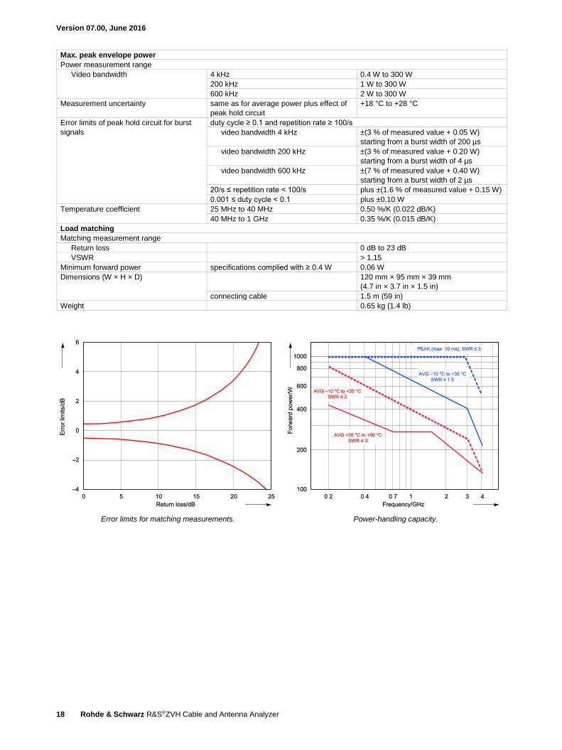
Error limits for matching measurements.
Power-handling capacity.
Version 07.00, June 2016
Rohde & Schwarz R&S®ZVH Cable and Antenna Analyzer 19
R&S®FSH-Z44 directional power sensor Frequency range 200 MHz to 4 GHz
Power measurement range 30 mW to 300 W
VSWR referenced to 50 Ω 200 MHz to 3 GHz < 1.07
3 GHz to 4 GHz < 1.12
Power-handling capacity depending on temperature and matching
(see diagram on next page)
120 W to 1000 W
Insertion loss 200 MHz to 1.5 GHz < 0.06 dB
1.5 GHz to 4 GHz < 0.09 dB
Directivity 200 MHz to 3 GHz > 30 dB
3 GHz to 4 GHz > 26 dB
Average power
Power measurement range CF: ratio of peak envelope power to average power
CW, FM, PM, FSK, GMSK 30 mW to 300 W
LTE, 3GPP WCDMA, cdmaOne,
CDMA2000®, DAB, DVB-T
30 mW to 120 W
other modulated signals 30 mW to 300 W/CF
Measurement uncertainty sine signal, +18 °C to +28 °C, no zero offset
200 MHz to 300 MHz 4.0 % of measured value (0.17 dB)
300 MHz to 4 GHz 3.2 % of measured value (0.14 dB)
Zero offset after zeroing ±4 mW
Range of typical measurement error
with modulation
FM, PM, FSK, GMSK 0 % of measured value (0 dB)
AM (80 %) ±3 % of measured value (±0.13 dB)
two CW carriers with identical power ±2 % of measured value (±0.09 dB)
π/4-DQPSK ±2 % of measured value (±0.09 dB)
EDGE ±0.5 % of measured value (±0.02 dB) 4
cdmaOne, DAB ±1 % of measured value (±0.04 dB) 4
3GPP WCDMA, CDMA2000® ±2 % of measured value (±0.09 dB) 4
DVB-T ±2 % of measured value (±0.09 dB) 4
Temperature coefficient 200 MHz to 300 MHz 0.40 %/K (0.017 dB/K)
300 MHz to 4 GHz 0.25 %/K (0.011 dB/K)
Max. peak envelope power
Power measurement range
DAB, DVB-T, cdmaOne, CDMA2000®,
3GPP WCDMA
4 W to 300 W
Other signals at video bandwidth 4 kHz 0.4 W to 300 W
200 kHz 1 W to 300 W
4 MHz 2 W to 300 W
Measurement uncertainty +18 °C to +28 °C same as for average power plus effect of
peak hold circuit
Error limits of peak hold circuit for burst
signals
duty cycle ≥ 0.1 and repetition rate ≥ 100/s
video bandwidth 4 kHz ±(3 % of measured value + 0.05 W)
starting from a burst width of 100 µs
video bandwidth 200 kHz ±(3 % of measured value + 0.20 W)
starting from a burst width of 4 µs
video bandwidth 4 MHz ±(7 % of measured value + 0.40 W)
starting from a burst width of 1 µs
20/s ≤ repetition rate < 100/s plus ±(1.6 % of measured value + 0.15 W)
0.001 ≤ duty cycle < 0.1 plus ±0.10 W
burst width ≥ 0.5 µs plus ±5 % of measured value
burst width ≥ 0.2 µs plus ±10 % of measured value
Range of typical measurement error of
peak hold circuit
video bandwidth 4 MHz and standard selected on the R&S®FSH
cdmaOne, DAB ±(5 % of measured value + 0.4 W)
DVB-T, CDMA2000®, 3GPP WCDMA ±(15 % of measured value + 0.4 W)
Temperature coefficient 200 MHz to 300 MHz 0.50 %/K (0.022 dB/K)
300 MHz to 4 GHz 0.35 %/K (0.015 dB/K)
4 If standard is selected on the R&S®ZVH.
Version 07.00, June 2016
20 Rohde & Schwarz R&S®ZVH Cable and Antenna Analyzer
Load matching
Matching measurement range
Return loss 200 MHz to 3 GHz 0 dB to +23 dB
VSWR 3 GHz to 4 GHz 0 dB to +20 dB
VSWR 200 MHz to 3 GHz > 1.15
3 GHz to 4 GHz > 1.22
Minimum forward power specifications complied with ≥ 0.2 W 0.03 W
Dimensions (W × H × D) 120 mm × 95 mm × 39 mm
(4.7 in × 3.7 in × 1.5 in)
connecting cable 1.5 m (59 in)
Weight 0.65 kg (1.4 lb)
Error limits for matching measurements.
Power-handling capacity.
R&S®HA-Z240 GPS receiver GPS location indication latitude, longitude
Reference frequency uncertainty GPS on, ≥ 1 minute after satellite lock ±2.5 × 10⁻⁸
up to 30 minutes after losing satellite lock ±5 × 10⁻⁸
Temperature operating temperature range –20 °C to +55 °C
storage temperature range –40 °C to +70 °C
Climatic loading GPS receiver module IEC 60529 IPX7 level
Connector 7-contact male (type Binder 712)
Power consumption 0.45 W (nom.)
Test marks FCC, CE
Dimensions Ø× H 61 mm × 19.5 mm (2.4 in × 0.8 in)
cable length 5 m (16.4 ft)
Weight 200 g (0.4 lb)
Version 07.00, June 2016
Rohde & Schwarz R&S®ZVH Cable and Antenna Analyzer 21
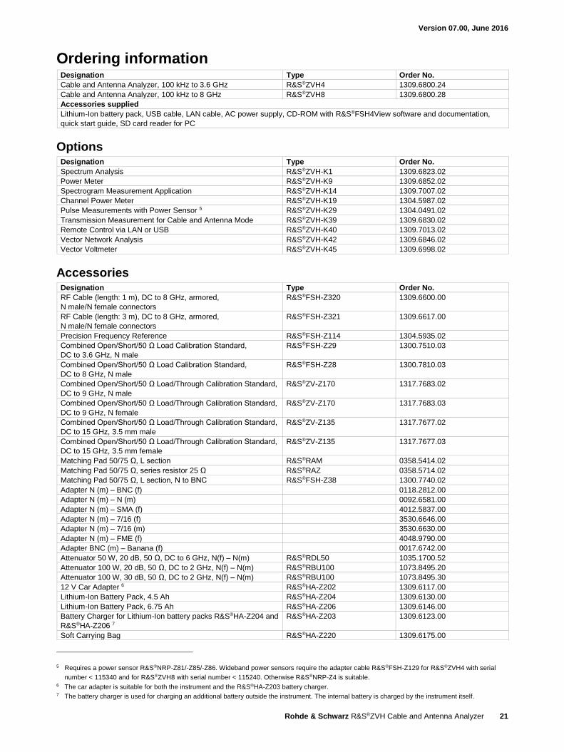
Ordering information Designation Type Order No.
Cable and Antenna Analyzer, 100 kHz to 3.6 GHz R&S®ZVH4 1309.6800.24
Cable and Antenna Analyzer, 100 kHz to 8 GHz R&S®ZVH8 1309.6800.28
Accessories supplied
Lithium-Ion battery pack, USB cable, LAN cable, AC power supply, CD-ROM with R&S®FSH4View software and documentation,
quick start guide, SD card reader for PC
Options Designation Type Order No.
Spectrum Analysis R&S®ZVH-K1 1309.6823.02
Power Meter R&S®ZVH-K9 1309.6852.02
Spectrogram Measurement Application R&S®ZVH-K14 1309.7007.02
Channel Power Meter R&S®ZVH-K19 1304.5987.02
Pulse Measurements with Power Sensor 5 R&S®ZVH-K29 1304.0491.02
Transmission Measurement for Cable and Antenna Mode R&S®ZVH-K39 1309.6830.02
Remote Control via LAN or USB R&S®ZVH-K40 1309.7013.02
Vector Network Analysis R&S®ZVH-K42 1309.6846.02
Vector Voltmeter R&S®ZVH-K45 1309.6998.02
Accessories Designation Type Order No.
RF Cable (length: 1 m), DC to 8 GHz, armored,
N male/N female connectors
R&S®FSH-Z320 1309.6600.00
RF Cable (length: 3 m), DC to 8 GHz, armored,
N male/N female connectors
R&S®FSH-Z321 1309.6617.00
Precision Frequency Reference R&S®FSH-Z114 1304.5935.02
Combined Open/Short/50 Ω Load Calibration Standard,
DC to 3.6 GHz, N male
R&S®FSH-Z29 1300.7510.03
Combined Open/Short/50 Ω Load Calibration Standard,
DC to 8 GHz, N male
R&S®FSH-Z28 1300.7810.03
Combined Open/Short/50 Ω Load/Through Calibration Standard,
DC to 9 GHz, N male
R&S®ZV-Z170 1317.7683.02
Combined Open/Short/50 Ω Load/Through Calibration Standard,
DC to 9 GHz, N female
R&S®ZV-Z170 1317.7683.03
Combined Open/Short/50 Ω Load/Through Calibration Standard,
DC to 15 GHz, 3.5 mm male
R&S®ZV-Z135 1317.7677.02
Combined Open/Short/50 Ω Load/Through Calibration Standard,
DC to 15 GHz, 3.5 mm female
R&S®ZV-Z135 1317.7677.03
Matching Pad 50/75 Ω, L section R&S®RAM 0358.5414.02
Matching Pad 50/75 Ω, series resistor 25 Ω R&S®RAZ 0358.5714.02
Matching Pad 50/75 Ω, L section, N to BNC R&S®FSH-Z38 1300.7740.02
Adapter N (m) – BNC (f) 0118.2812.00
Adapter N (m) – N (m) 0092.6581.00
Adapter N (m) – SMA (f) 4012.5837.00
Adapter N (m) – 7/16 (f) 3530.6646.00
Adapter N (m) – 7/16 (m) 3530.6630.00
Adapter N (m) – FME (f) 4048.9790.00
Adapter BNC (m) – Banana (f) 0017.6742.00
Attenuator 50 W, 20 dB, 50 Ω, DC to 6 GHz, N(f) – N(m) R&S®RDL50 1035.1700.52
Attenuator 100 W, 20 dB, 50 Ω, DC to 2 GHz, N(f) – N(m) R&S®RBU100 1073.8495.20
Attenuator 100 W, 30 dB, 50 Ω, DC to 2 GHz, N(f) – N(m) R&S®RBU100 1073.8495.30
12 V Car Adapter 6 R&S®HA-Z202 1309.6117.00
Lithium-Ion Battery Pack, 4.5 Ah R&S®HA-Z204 1309.6130.00
Lithium-Ion Battery Pack, 6.75 Ah R&S®HA-Z206 1309.6146.00
Battery Charger for Lithium-Ion battery packs R&S®HA-Z204 and
R&S®HA-Z206 7
R&S®HA-Z203 1309.6123.00
Soft Carrying Bag R&S®HA-Z220 1309.6175.00
5 Requires a power sensor R&S®NRP-Z81/-Z85/-Z86. Wideband power sensors require the adapter cable R&S®FSH-Z129 for R&S®ZVH4 with serial
number < 115340 and for R&S®ZVH8 with serial number < 115240. Otherwise R&S®NRP-Z4 is suitable. 6 The car adapter is suitable for both the instrument and the R&S®HA-Z203 battery charger. 7 The battery charger is used for charging an additional battery outside the instrument. The internal battery is charged by the instrument itself.
Version 07.00, June 2016
22 Rohde & Schwarz R&S®ZVH Cable and Antenna Analyzer
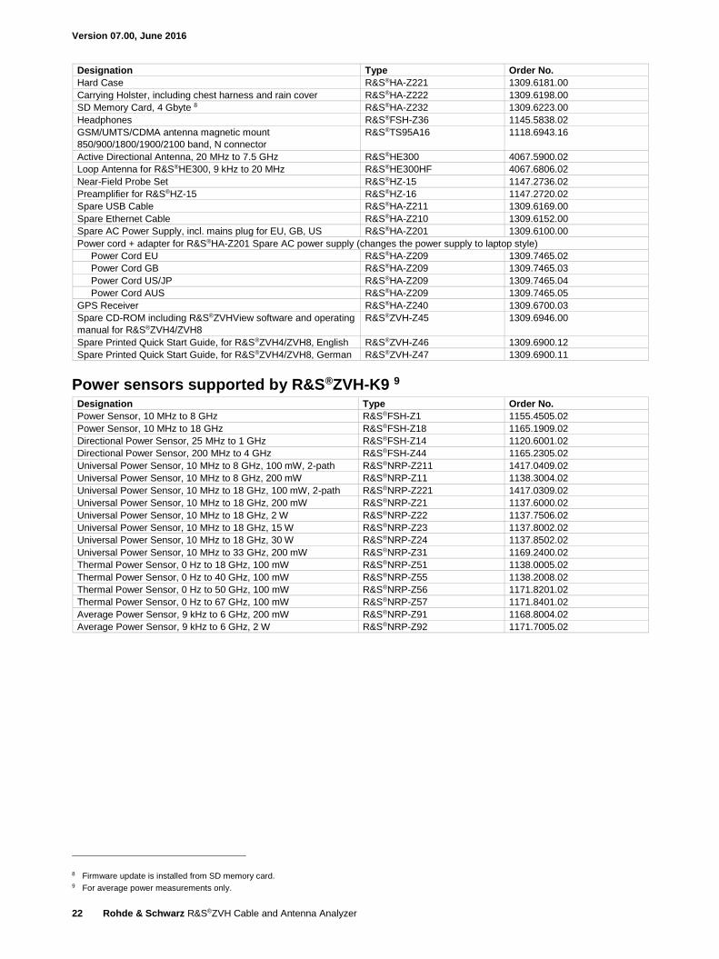
Designation Type Order No.
Hard Case R&S®HA-Z221 1309.6181.00
Carrying Holster, including chest harness and rain cover R&S®HA-Z222 1309.6198.00
SD Memory Card, 4 Gbyte 8 R&S®HA-Z232 1309.6223.00
Headphones R&S®FSH-Z36 1145.5838.02
GSM/UMTS/CDMA antenna magnetic mount
850/900/1800/1900/2100 band, N connector
R&S®TS95A16 1118.6943.16
Active Directional Antenna, 20 MHz to 7.5 GHz R&S®HE300 4067.5900.02
Loop Antenna for R&S®HE300, 9 kHz to 20 MHz R&S®HE300HF 4067.6806.02
Near-Field Probe Set R&S®HZ-15 1147.2736.02
Preamplifier for R&S®HZ-15 R&S®HZ-16 1147.2720.02
Spare USB Cable R&S®HA-Z211 1309.6169.00
Spare Ethernet Cable R&S®HA-Z210 1309.6152.00
Spare AC Power Supply, incl. mains plug for EU, GB, US R&S®HA-Z201 1309.6100.00
Power cord + adapter for R&S®HA-Z201 Spare AC power supply (changes the power supply to laptop style)
Power Cord EU R&S®HA-Z209 1309.7465.02
Power Cord GB R&S®HA-Z209 1309.7465.03
Power Cord US/JP R&S®HA-Z209 1309.7465.04
Power Cord AUS R&S®HA-Z209 1309.7465.05
GPS Receiver R&S®HA-Z240 1309.6700.03
Spare CD-ROM including R&S®ZVHView software and operating
manual for R&S®ZVH4/ZVH8
R&S®ZVH-Z45 1309.6946.00
Spare Printed Quick Start Guide, for R&S®ZVH4/ZVH8, English R&S®ZVH-Z46 1309.6900.12
Spare Printed Quick Start Guide, for R&S®ZVH4/ZVH8, German R&S®ZVH-Z47 1309.6900.11
Power sensors supported by R&S®ZVH-K9 9 Designation Type Order No.
Power Sensor, 10 MHz to 8 GHz R&S®FSH-Z1 1155.4505.02
Power Sensor, 10 MHz to 18 GHz R&S®FSH-Z18 1165.1909.02
Directional Power Sensor, 25 MHz to 1 GHz R&S®FSH-Z14 1120.6001.02
Directional Power Sensor, 200 MHz to 4 GHz R&S®FSH-Z44 1165.2305.02
Universal Power Sensor, 10 MHz to 8 GHz, 100 mW, 2-path R&S®NRP-Z211 1417.0409.02
Universal Power Sensor, 10 MHz to 8 GHz, 200 mW R&S®NRP-Z11 1138.3004.02
Universal Power Sensor, 10 MHz to 18 GHz, 100 mW, 2-path R&S®NRP-Z221 1417.0309.02
Universal Power Sensor, 10 MHz to 18 GHz, 200 mW R&S®NRP-Z21 1137.6000.02
Universal Power Sensor, 10 MHz to 18 GHz, 2 W R&S®NRP-Z22 1137.7506.02
Universal Power Sensor, 10 MHz to 18 GHz, 15 W R&S®NRP-Z23 1137.8002.02
Universal Power Sensor, 10 MHz to 18 GHz, 30 W R&S®NRP-Z24 1137.8502.02
Universal Power Sensor, 10 MHz to 33 GHz, 200 mW R&S®NRP-Z31 1169.2400.02
Thermal Power Sensor, 0 Hz to 18 GHz, 100 mW R&S®NRP-Z51 1138.0005.02
Thermal Power Sensor, 0 Hz to 40 GHz, 100 mW R&S®NRP-Z55 1138.2008.02
Thermal Power Sensor, 0 Hz to 50 GHz, 100 mW R&S®NRP-Z56 1171.8201.02
Thermal Power Sensor, 0 Hz to 67 GHz, 100 mW R&S®NRP-Z57 1171.8401.02
Average Power Sensor, 9 kHz to 6 GHz, 200 mW R&S®NRP-Z91 1168.8004.02
Average Power Sensor, 9 kHz to 6 GHz, 2 W R&S®NRP-Z92 1171.7005.02
8 Firmware update is installed from SD memory card. 9 For average power measurements only.
Version 07.00, June 2016
Rohde & Schwarz R&S®ZVH Cable and Antenna Analyzer 23
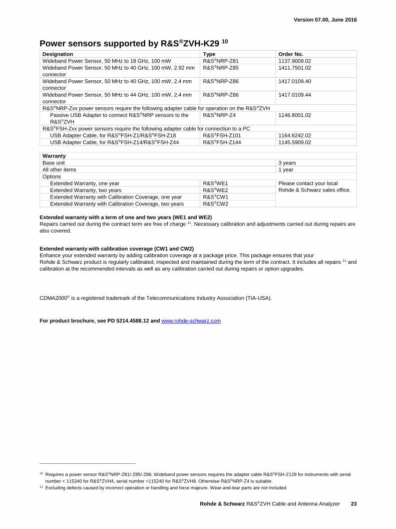
Power sensors supported by R&S®ZVH-K29 10 Designation Type Order No.
Wideband Power Sensor, 50 MHz to 18 GHz, 100 mW R&S®NRP-Z81 1137.9009.02
Wideband Power Sensor, 50 MHz to 40 GHz, 100 mW, 2.92 mm
connector
R&S®NRP-Z85 1411.7501.02
Wideband Power Sensor, 50 MHz to 40 GHz, 100 mW, 2.4 mm
connector
R&S®NRP-Z86 1417.0109.40
Wideband Power Sensor, 50 MHz to 44 GHz, 100 mW, 2.4 mm
connector
R&S®NRP-Z86 1417.0109.44
R&S®NRP-Zxx power sensors require the following adapter cable for operation on the R&S®ZVH
Passive USB Adapter to connect R&S®NRP sensors to the
R&S®ZVH
R&S®NRP-Z4 1146.8001.02
R&S®FSH-Zxx power sensors require the following adapter cable for connection to a PC
USB Adapter Cable, for R&S®FSH-Z1/R&S®FSH-Z18 R&S®FSH-Z101 1164.6242.02
USB Adapter Cable, for R&S®FSH-Z14/R&S®FSH-Z44 R&S®FSH-Z144 1145.5909.02
Warranty
Base unit 3 years
All other items 1 year
Options
Extended Warranty, one year R&S®WE1 Please contact your local
Rohde & Schwarz sales office. Extended Warranty, two years R&S®WE2
Extended Warranty with Calibration Coverage, one year R&S®CW1
Extended Warranty with Calibration Coverage, two years R&S®CW2
Extended warranty with a term of one and two years (WE1 and WE2)
Repairs carried out during the contract term are free of charge 11. Necessary calibration and adjustments carried out during repairs are
also covered.
Extended warranty with calibration coverage (CW1 and CW2)
Enhance your extended warranty by adding calibration coverage at a package price. This package ensures that your
Rohde & Schwarz product is regularly calibrated, inspected and maintained during the term of the contract. It includes all repairs 11 and
calibration at the recommended intervals as well as any calibration carried out during repairs or option upgrades.
CDMA2000® is a registered trademark of the Telecommunications Industry Association (TIA-USA).
For product brochure, see PD 5214.4588.12 and www.rohde-schwarz.com
10 Requires a power sensor R&S®NRP-Z81/-Z85/-Z86. Wideband power sensors requires the adapter cable R&S®FSH-Z129 for instruments with serial
number < 115340 for R&S®ZVH4, serial number <115240 for R&S®ZVH8. Otherwise R&S®NRP-Z4 is suitable. 11 Excluding defects caused by incorrect operation or handling and force majeure. Wear-and-tear parts are not included.
R&S® is a registered trademark of Rohde & Schwarz GmbH & Co. KG
Trade names are trademarks of the owners
PD 5214.4588.22 | Version 07.00 | June 2016 (as)
R&S®ZVH Cable and Antenna Analyzer
Data without tolerance limits is not binding | Subject to change
© 2010 - 2016 Rohde & Schwarz GmbH & Co. KG | 81671 Munich, Germany
Service that adds value Worldwide Local and personalized Customized and flexible Uncompromising quality Long-term dependability
5214
.458
8.22
07.
00 P
DP
1 e
n
About Rohde & SchwarzThe Rohde & Schwarz electronics group offers innovative solutions in the following business fields: test and mea-surement, broadcast and media, secure communications, cybersecurity, radiomonitoring and radiolocation. Founded more than 80 years ago, this independent company has an extensive sales and service network and is present in more than 70 countries. The electronics group is among the world market leaders in its established business fields. The company is headquartered in Munich, Germany. It also has regional headquarters in Singapore and Columbia, Maryland, USA, to manage its operations in these regions.
Sustainable product design Environmental compatibility and eco-footprint Energy efficiency and low emissions Longevity and optimized total cost of ownership
Certified Environmental Management
ISO 14001Certified Quality Management
ISO 9001
Regional contact Europe, Africa, Middle East | +49 89 4129 12345 [email protected]
North America | 1 888 TEST RSA (1 888 837 87 72) [email protected]
Latin America | +1 410 910 79 88 [email protected]
Asia Pacific | +65 65 13 04 88 [email protected]
China | +86 800 810 82 28 | +86 400 650 58 96 [email protected]
Rohde & Schwarz GmbH & Co. KGwww.rohde-schwarz.com
Rohde & Schwarz trainingwww.training.rohde-schwarz.com
5214458822
ZVH_dat-sw_en_5214-4588-22_v0700_cover.indd 2 02.06.2016 18:04:00