Embed Size (px)
Citation preview

RTL.SDR DIY KITs
Installation instructions
V2.01
Note the installation instructions apply only provided by the shop KITs.
The note is not applicable to pirated KITs.
BA5SBA [email protected]

1; check the kits plastic bag all parts contrast images, attention to keep
good in a small ferrite bead, don't lose it.
2; SMD components all 0805 package have welding is PCB, please
check whether there is leakage solder and cold solder joint.

3; welding of SMA interface and miniUSB interface.
Note that, on the back of the SMA interface also to welding, fixed pin
USB interface to welding firm

4; welding jumper and LED. Note, the long foot is LED positive.
A P jumper circuit board inside is arranged to the active antenna for
the power supply, connected to the A position, the red LED light,
through the power output of the 5V to the antenna interface, power supply
in active antenna amplifier. The default connection to P .
Pin bending direction of LED refer to the above picture, careful not to
mistake or LED not bright.

5; welding electrolytic capacitor, note capacitor polarity, long legs is
capacitor the positive electrode. Do not reverse the welding.
Note that the polarity of the capacitor refer to the above picture check.
After welding, cut off the excess part, take good care of cut pins, later
need to use.

Note that the polarity of the capacitor refer to the above picture check.
6; inductance coil winding and installation. Pictured above is provided
KITs enameled wire, please open it tidy.

Finishing a good。
Please find a diameter of 3 mm of objects, such as the drill, screwdriver,
here are using a 3mm drill bit.。
Installation position of the coil, provides the enameled wire can be
directly welded enameled wire.
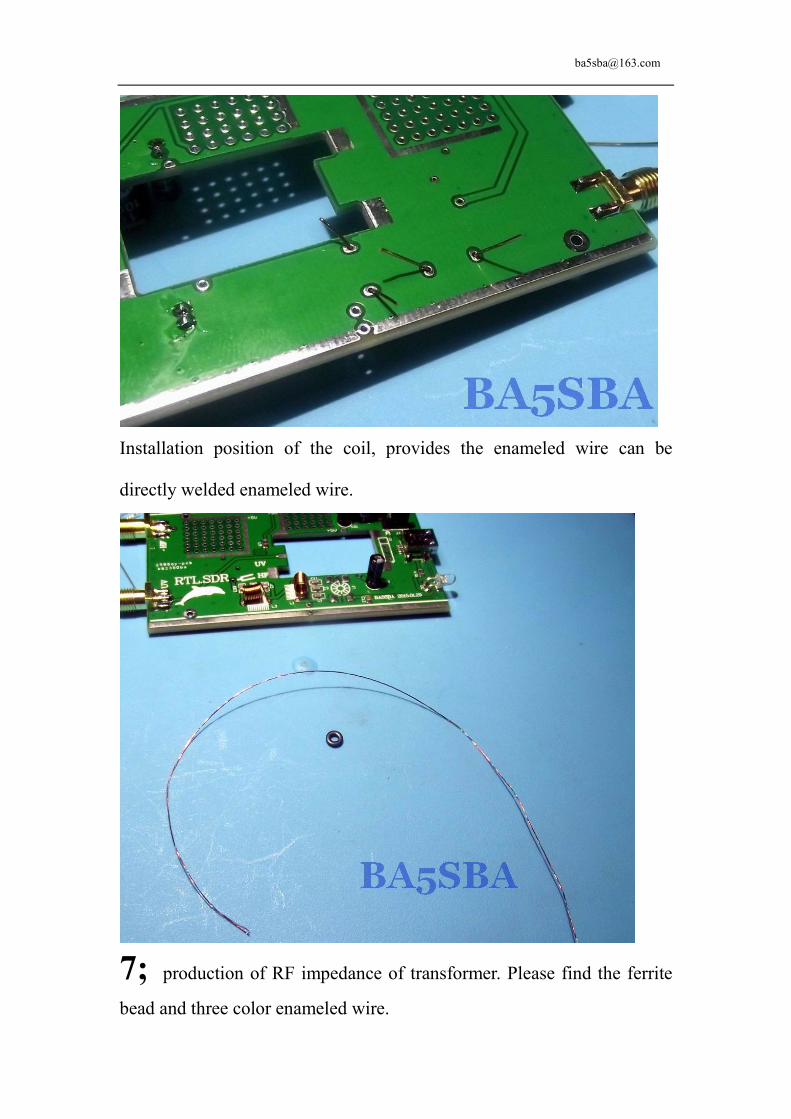
7; production of RF impedance of transformer. Please find the ferrite
bead and three color enameled wire.

On the magnetic ring to wear around 9 turns with tricolor enameled wire.
Cut off the excess, take good care of the excess part, will also use.
The color of enameled wire to separate, pay attention to the head and tail
to be separated into different sides

In the PCB board welding position reference above.
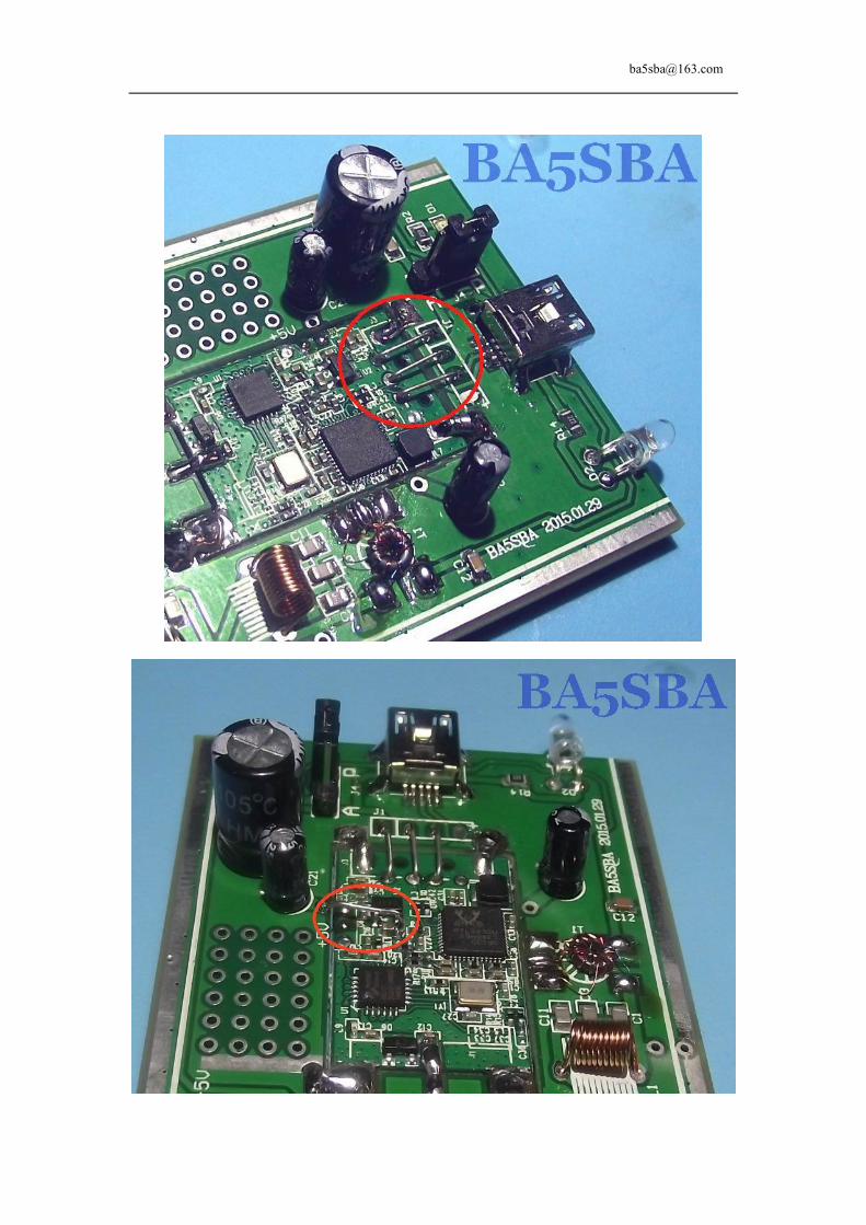
8; decomposition of DVB-T Dongle Stick。

The circuit board is removed to the circuit board is embedded into the kits
of the.
Reliable welding solder red circles part.

Reliable welding solder red circles part. Note do not leak welding red
arrow part
9; with capacitor pin retention of various welding wire jumper。

10; cut two 1 inch with the rest of the three color enameled wire, and
then in the end of tin.
Welded to the RTL2832 pins 4 and 5.

QUICK START GUIDE This page is a guide aimed at helping anyone set up a cheap radio scanner based on the
RTL-SDR
software defined radio as fast as possible on a Windows system.
http://www.rtl-sdr.com/rtl-sdr-quick-start-guide/
SDRSharp Guide
A good guide to learning how to use SDRSharp and what all the options do can be found here.
http://www.atouk.com/SDRSharpQuickStart.html
Another great illustrated guide can be found here.
http://tylerwatt12.com/tips-for-using-sdr/
RTL-SDR.COM THE BIG LIST OF RTL-SDR SUPPORTED SOFTWARE
http://www.rtl-sdr.com/big-list-rtl-sdr-supported-software/
Antenna Long Wire con Balun 9:1
http://www.radioamatoripeligni.it/i6ibe/balun9a1/balun9a1.htm
Alternative Installation Procedure for RTL.SDR and HDSDR
http://www.hamradioscience.com/alternative-installation-procedure-for-rtl-sticks-and-hdsdr/
Receiving LF/MF/HF (0 - 30 MHz)
The antenna must be connected to the HF input port
The program of SDR # with RTL configured to direct sampling of the signal Q, as
shown in the following figure:

signal receiving HF band needs to meet the HF Antennas such as Long Wire, Random Wire, Dipole etc.. To have
a good effect need matching antenna.
How to set the Gain
The gain can be adjusted in SDR# by clicking on the Configure button
which looks like a cog. When tuning the RF gain you are trying to get the
signal as strong as possible, whilst keeping the noise floor as low as
possible. Start with a low gain setting, and slowly increase the gain slider.
Watch in the frequency spectrum as the signal strength increases, but stop
just before the point at which the noise floor starts to rise.
The noise floor is the part of the frequency spectrum where there are no
signals.