Embed Size (px)
Citation preview
[Product#] SMP IO-2230-K and KRCatalog DataCA912008EN
Effective February 2020Supersedes October 2019
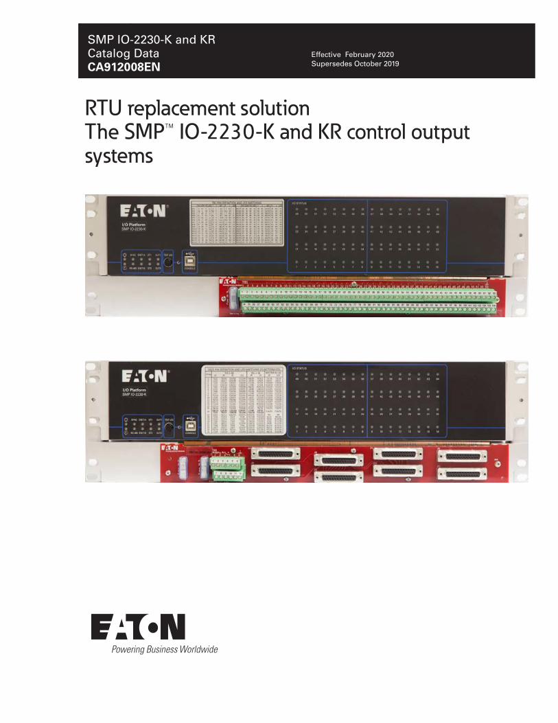
RTU replacement solution The SMP™ IO-2230-K and KR control output systems

SMP IO-2230-K (KR) Catalog Data....................................................................................................................1
Description.....................................................................................................................................................1
General features........................................................................................................................................... 2
Cybersecurity.................................................................................................................................................3
Benefits..........................................................................................................................................................3
System architecture and I/O features...........................................................................................................4
Front panel.............................................................................................................................................5
Rear panel............................................................................................................................................. 7
Specifications.............................................................................................................................................. 11
Certifications and compliancy notes........................................................................................................... 16
Temperature derating..................................................................................................................................16
Dimension drawings....................................................................................................................................17
Ordering information................................................................................................................................... 18
Accessories and cables.............................................................................................................................. 19

Catalog Data CA912008ENIssue date February 2020
Description
This document describes the hardware layout and functionality of the SMP IO-2230-K (KR) system, which isbased on the SMP IO-2230 distributed I/O platform.The RTU replacement solutionEaton’s new solution for RTU replacement solution provides utilities with a cost-effective answer to upgradinglegacy RTUs with cybersecurity at the uppermost in mind. Based on the utility hardened and proven Eaton’sSMP family of substation automation products, the SMP SG-42xx automation platform and the SMPIO-2230 distributed I/O unit, our basic hardware agnostic replacement solution, supports most legacy RTUconfigurations. Eaton's RTU replacement solution is easily adaptable to any specific RTU deployment scenario(e.g. GE D20) and allows for great cost savings on field installation man-hours and service interruptionsbecause it keeps the existing field wiring.
The SMP Gateway automation platformBoth Eaton’s SMP Gateway automation platform models are substation-grade gateways with a provenhistory in data acquisition and distribution automation applications, as protocol conversion device andintegration solution for secure IED remote access. They are recognized as one of the most efficient andreliable automation platforms on the market and are perfect for distributed automation.The SMP IO-2230 distributed I/O platformThe SMP IO-2230 is Eaton’s new generation of substation-grade distributed I/O platforms; it is speciallydesigned to meet modern industry and utility requirements and is fully integrated with the SMP Manager andTools application for device configuration and maintenance. It integrates seamlessly with the SMP Gatewayautomation platforms–simplifying both system setup and commissioning.The SMP IO-2230 distributed I/O platform uses a template-driven configuration tool, SMP Config, and includesnumerous cybersecurity features to help utilities meet their compliance requirements, including NERC CIP(certified under UL 2900-2-2).
Figure 1. The SMP IO-2230-K (KR)
www.eaton/smartgrid 1

RTU replacement system SMP IO-2230-K (KR) Catalog Data CA912008ENIssue date February 2020
General features
Hardware• Form factor: 3U rackmount
• SMP IO-2230 is servicable without removingthe chassis form the rack
• Individual LEDs for each I/O
• No moving part
• Two built-in Form C relays for system alarm(configurable)
• System status LEDs
• Multi-function button (Local/Remote selectorand Test LED)
• Local/Remote status LED
• Front USB 2.0 maintenance port (Type B)
• Custom length cables available
• Supported polarity reversal for power supplyand Inputs/Outputs
Protocols• DNP3, IEC 61850, GOOSE Serial or TCP/IP
links
• DNP3 event queue (up to 1000 events/slave)
• Up to 5 slave instances
Communication and Web interface• RS-485 serial interface
• 2 x 10/100 Mb/s Ethernet ports or 2 x 100 Mb/soptical Ethernet ports
• Daisy chain Ethernet capabilities
• Web interface for I/O commissioning
• Secured remote maintenance using transparentconnection (SMP Gateway and IMSpassthrough)
Software• Linux®-based operating system
• Seamless integration with the SMP Gateway
• Access to SMP Manager's Tools
• Remote management (firmware upgrade,setting changes, license update)
• Configuration with SMP Config (also forstandalone units), multi protocols/instances,configurable point mapping
• Offline and template-driven configuration
• Use of SMP Stats, SMP Log and SMP Trace
• Micro PLC for local programmable logic (fastand complete PLC functions)
• Ready for remote management via EnterpriseManagement Software (IMS)
• System alarms
Mapping• Predefined mappings
• Configurable mappings
• Serial number, version, internal status, currenttime, last reset time and more are available inthe protocol mapping
• Exportable DNP3 protocol device XML profile
System• Integrated self-diagnostics
• Integrated watchdog timer
• Real-time clock (with battery backup)
• Internal clock synchronization using IRIG-B,NTP or via protocols
• Local/Remote switching mechanism and state(logical points)
• Logs support (Security, System)
2 www.eaton/smartgrid

Catalog Data CA912008ENIssue date February 2020 RTU replacement system SMP IO-2230-K (KR)
Cybersecurity
• UL2900-2-2 compliant: Standard for SoftwareCybersecurity for Network-ConnectableDevices
• IEEE 1686-2013 compliant
• Integrated Ethernet firewall
• Ability to disable any unused port (reportenabled-disabled ports)
• Secure maintenance connection (TLS) viaSMP Gateway Passthrough or via direct SMPManager connection
• AES-128/256 encryption
• Secure USB maintenance port
• Secure command shell
• Access management (log, lockup, etc.)
• Account management: Strong passwords
Single Admin account
User accounts and user groups
Detailed group permissions
• All system components digitally signed
• Settings integrity validation
• Factory reset in case of Admin password loss
BenefitsWith its robust and scalable design Eaton's RTU replacement solution is flexible and adapts to evolvingautomation requirements.
Reliability• Designed to evolve through regular software
and firmware updates, ensuring a future-proofautomation system
• Helps meet NERC CIP requirements bysecuring IED remote access and enhancingSCADA communication links
Scalability• Universal power supply (wide input ac and dc
voltage range), for connection flexibility
• Use of open industry protocols (standard DNP3,GOOSE messaging or IEC 61850 over a TCP/IP or RS-485 link) with over 80 protocols tointegrate other IEDs in the substation via theautomation platform
Easy integration• Complete support for the SMP Tools
• Easy configuration using SMP Manager'sSMP Config
• Simplified pre-loading operation of existingconfiguration into the SMP Gateway prior toinstallation
Productivity• 70% labor cost reduction compared to a
traditional RTU replacement solution due to theuse of existing wiring
• Offline configuration tools
• Web interface for I/O commissioning
• Uses the same management applicationsas the SMP Gateway automation platform(SMP Manager)
• Seamless I/O integration between theSMP Gateway and distributed I/O unit
• Enhanced automation capabilities using theIEC 61131-3 Soft PLC of the SMP Gatewayautomation platform and/or the micro PLC ofthe SMP IO-2230 distributed I/O unit
www.eaton/smartgrid 3

RTU replacement system SMP IO-2230-K (KR) Catalog Data CA912008ENIssue date February 2020
System architecture and I/O featuresThe following I/O features are available for the RTU replacement systems, I/Os types availability depends onthe specific model.
Analog inputs• High/Low warning support
• Deadband, scaling and units
• User calibration at fixed ambient temperature
Binary outputs• Output protection against single component
failure
• Trip/close pair, latch, pulse, pulse pair support
• Persisted operation counter/operation time
• Binary points software polarity reversal
• Control queuing allows up to 10 parallelrequests, sequentially processed when thesame point is targeted
Binary inputs• AC and DC inputs
• Tolerance/Intolerance filtering
• Chatter protection
• Fail safe circuit (active level in normal state)
• Binary points software polarity reversal
• Timetag at the beginning or end of the filtering(setting)
• Persisted counters (total transitions, up/downdirection), with deadband, scaling and roll overdetection.
• Freeze, clear, freeze and clear counterssupport
Table 1. RTU replacement system, available models
Type Model Available I/Os
Rackmount (3U) SMP IO-2230-A 32 analog inputs: disconnect terminations
Rackmount (3U) SMP IO-2230-K 32 control outputs: disconnect terminations (K) or DB25 connectors (KR)
Rackmount (3U) SMP IO-2230-S 64 status and alarm inputs: disconnect terminations
The SMP IO-2230-K (KR) configuration is fixed at 32 control outputs, the following features apply to thisSMP IO-2230 system:
• Possible control output configurations: 32 Trip/Close pairs
24 Trip/Close pairs and 4 Raise/Lower pairs
16 Trip/Close pairs and 8 Raise/Lower pairs
8 Trip/Close pairs and 12 Raise/Lower pairs
16 Raise/Lower pairs
32 isolated Form C contact control outputs
• Relays can be configured separately instead ofin groups of 8 (K model only)
• Control output methods (hardware and softwareadjustable): Pulse duration
Latched-output (discrete timed/latch relayfunctionality supported)
• Matrix function supported on the KR model(DB25 connectors)
• Can be configured to be connected to a D20 KIinterposing relay or to an LPL
Important: Please note that the operating modes for Raise/Lower, matrix, D20KI and LPL are hardwareready, however the related software functions are coming soon. Please call Technical support if you want touse these configuration modes.
4 www.eaton/smartgrid

Catalog Data CA912008ENIssue date February 2020 RTU replacement system SMP IO-2230-K (KR)
Front panelThis section shows the SMP IO-2230 system front panel and identifies its main components.
Figure 2. The front panel of the SMP IO-2230-K unit
Figure 3. The front panel of the SMP IO-2230-KR unitThe following table describes the front panel components related to the previous figure:
Table 2. Front panel components of the SMP IO-2230-K (KR) unit
ID Name Description
1 Power LED. This LED indicates the status of the SMP IO-2230 system internal powersupply.
2 Watchdog timer status LED.
3 SYNC Clock synchronization LED.
This LED indicates the synchronization status of the SMP IO-2230 system connected toan IRIG-B synchronization source.
4 RS-485 Built-in RS-485 serial port activity LED.
www.eaton/smartgrid 5

RTU replacement system SMP IO-2230-K (KR) Catalog Data CA912008ENIssue date February 2020
ID Name Description
5 ENET1A, ENET1B Built-in ENET1A and ENET1B2 port activity LEDs.
The two Ethernet ports are used as Ethernet switches for daisy-chain connections.Each LED indicates the speed and activity level of the corresponding Ethernet port(switch).
Note: The statistics page (SMP Stats) located under /System/Internals/VitalSystem information displays information about the network adapters in theNetwork Settings section of the page.
6 ST1 Status LED 1.
This LED indicates the various steps the SMP IO-2230 system goes through during thestartup sequence.
8 OUT1, OUT2 On board relay 1 and relay 2
Each LED indicates the relay status.
Table 3. On board relays LED, color description
Color Meaning
Off The relay is not energized
Green The relay is energized
9 TEST LED Multi-function button used:
• To test the SMP IO-2230 system front panel LEDs. When pressed, all LEDs shouldlight.
• To toggle between local and remote mode for control operation. When the system isstarted, pressing the button for at least five (5) seconds will switch from the currentmode to the other mode (i.e. from local to remote or from remote to local). Thecurrent operation mode is persisted upon device restart.
• To force the system to boot into rescue mode. To do so, press and hold the buttonduring the first five (5) seconds of the boot-up sequence, until the LEDs light up.The SMP IO-2230-K (KR) will then boot in rescue mode.
10 Reset Button(pinhole)
This reset button requires the use of a pin to activate the reset of the SMP IO-2230system. This is necessary in order to prevent accidental use to the button.
11 CONSOLE Type-B USB 2.0 port.
This port is used for maintenance and configuration of the SMP IO-2230 system; itis always enabled. This port is also used to access the SMP IO-2230 system's webinterface to monitor and control I/Os for commissioning.
12 I/O Status LEDs I/O activity/state for control outputs 1 to 32. LEDs 9 to 16, 25 to 32, 41 to 48 and 57 to64 are used (the other LEDs on the device are not used).
Each LED indicates the status of the point.
13 Terminal blocks orDB25 connectors
Terminal blocks, compresssion type (K) or DB25 connectors (KR) for connecting up to32 control outputs. The connectors are used to connect the existing field wiring to theSMP IO-2230-K (KR). When configured in wetting mode (Trip/Close and Raise/Loweroutput configurations only), a 2A fuse is protecting the circuit for the K model and 2 x 2Afuses are protecting the circuit for the KR model.Important: The Raise/Lower control output configuration is hardware ready, howeverits corresponding control output configuration using the pulse train (sofware related) iscoming soon. Please call Technical support if you want to use this configuration mode.
6 www.eaton/smartgrid

Catalog Data CA912008ENIssue date February 2020 RTU replacement system SMP IO-2230-K (KR)
ID Name Description
14 Label forterminations versusLED identification
Label for Terminal Block 1 (TB1) pin matching according to the control outputconfiguration and LED IDs for SMP IO-2230-K (KR).
Rear panelThis section shows the SMP IO-2230 system rear panel and identifies its main components.
Figure 4. The rear panel of the SMP IO-2230-K unit
Figure 5. The rear panel of the SMP IO-2230-KR unitThe following table describes the rear panel components related to the previous figure.
www.eaton/smartgrid 7

RTU replacement system SMP IO-2230-K (KR) Catalog Data CA912008ENIssue date February 2020
Table 4. Rear panel components of the SMP IO-2230-K (KR) unit
ID Name Description
1 Power supply terminalblock
Wiring terminals for power supply. Eaton recommends the use of a shielded cablewith twisted 18 to 12 AWG wires for the SMP IO-2230 system power supply terminalblock.
Note: If the SMP IO-2230 system is intended for use at ambient temperatures greaterthan 140°F (60°C), use a cable with a suitable temperature rating.Recommended torque for this terminal block is 0.49 N*m (4.3 lbf*in).
2 ENET1A, ENET1B Built-in Ethernet connectors (switch).
The following connector types are available for these built-in ports (both connectorsare of the same type):
• Shielded metallic RJ45 (standard)
• Fiber-optic LC (option)
3 OUT1, OUT2 2 NO/NC (normally open / normally closed) Form C relays: The OUT1 relay's NCcontact is pre-configured for system health monitoring (application). Both relays areavailable for system applications and can be activated through a system data outputpoint, if configured. When configured for system health monitoring, the OUT1 relay'sNC contact operates as follows:
The relay's NC contact remains closed until the SMP IO-2230 system is started.Thereafter, the contact is opened if the SMP IO-2230 system is working properly.In case of failure, the watchdog timer resets the SMP IO-2230 system and the NCcontact closes during the restart.
Eaton recommends the use of a shielded cable with twisted 28-14 AWG wires for thisterminal block. Recommended torque for this terminal block is 0.25 N*m (2.2 lbf*in).
4 RS-485 serial port Terminal block reserved for the serial RS-485 communication (COM1)
• 2-wire RS-485 support (multidrop)
• Up to 1200 m (4000 ft.)
• Up to 32 devices (multidrop)
Baud rates supported on this port: 300, 600, 1200, 1800, 2400, 4800, 9600, 19200,38400, 57600, 115200 bps
5 IRIG-B IN Terminal block reserved for the reception of a demodulated IRIG-B signal.
Eaton recommends the use of a shielded cable with twisted 22-16 AWG wires for theIRIG-B terminal block.
Recommended torque for this terminal block is 0.25 N*m (2.2 lbf*in).
6 System configuration When Eaton delivers an SMP IO-2230 system, an I/O configuration sticker is placedon the rear panel.
7 Grounding screw Screw-in protective earth ground connection terminal.
Eaton recommends the use of 14-2 AWG wires for the protective earth ground screw.
8 www.eaton/smartgrid

Catalog Data CA912008ENIssue date February 2020 RTU replacement system SMP IO-2230-K (KR)
ID Name Description
8 Configuration moduleinstallation for versionwith terminal blocks (K)
OR
Jumpers configurationfor version with DB25connectors (KR)
For SMP IO-2230-K system (using terminal blocks):
The Identification for the configuration module installation into the Output x ports forthe SMP IO-2230-K (KR). The three possible binary outputs mode of operation, foreach output are :
• NO-COM-NC (Form C)
• Trip/Close
• Raise/Lower
Important: The Raise/Lower control output configuration is hardware ready, howeverits corresponding control output configuration using the pulse train (sofware related) iscoming soon. Please call Technical support if you want to use this configuration mode.
There is only one configuration module for all control types, it is however inserted indifferent positions and orientation for the control types (pay attention to the semi-circlelocated on the module's handle).
For the SMP IO-2230-KR system (using the DB25 connectors):
Important: Please note that the operating modes for Raise/Lower, matrix, D20KI andLPL are hardware ready, however the related software functions are coming soon.Please call Technical support if you want to use these configuration modes.
Jumpers 8 to 13 are used for configuring the SMP IO-2230-KR operating mode, whichare:
• D20KI
• LPL
Jumpers 4 to 7 are used to configure the binary output modes of operation or thematrix row selection, which are:
• Trip/Close
• Raise/Lower
• Matrix row selection (used with the D20KI interposing relay panel)
www.eaton/smartgrid 9
RTU replacement system SMP IO-2230-K (KR) Catalog Data CA912008ENIssue date February 2020
ID Name Description
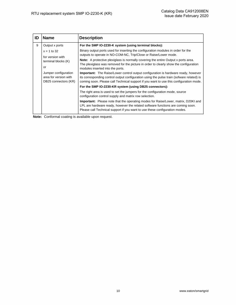
9 Output x ports
x = 1 to 32
for version withterminal blocks (K)
or
Jumper configurationarea for version withDB25 connectors (KR)
For the SMP IO-2230-K system (using terminal blocks):
Binary output ports used for inserting the configuration modules in order for theoutputs to operate in NO-COM-NC, Trip/Close or Raise/Lower mode.
Note: A protective plexiglass is normally covering the entire Output x ports area.The plexiglass was removed for the picture in order to clearly show the configurationmodules inserted into the ports.Important: The Raise/Lower control output configuration is hardware ready, howeverits corresponding control output configuration using the pulse train (sofware related) iscoming soon. Please call Technical support if you want to use this configuration mode.
For the SMP IO-2230-KR system (using DB25 connectors):
The right area is used to set the jumpers for the configuration mode, sourceconfiguration control supply and matrix row selection.
Important: Please note that the operating modes for Raise/Lower, matrix, D20KI andLPL are hardware ready, however the related software functions are coming soon.Please call Technical support if you want to use these configuration modes.
Note: Conformal coating is available upon request.
10 www.eaton/smartgrid

Catalog Data CA912008ENIssue date February 2020 RTU replacement system SMP IO-2230-K (KR)
Specifications
Table 5. General specifications
General specifications
Details Additional information
Dimensions Height: 5.52 in. (140 mm)
Width: 19 in. (482 mm)
Length: 9.75 in. (248 mm)
15 lb max (6.8 kg)
Warranty 10-year limited
Operatingtemperature
-40°F to +185°F* (-40°C to 85°C)
Typical use
* Safety marking is based ontemperature derating table
Storage temperature -40°F to +185°F (-40°C to 85°C)
Humidity 5 to 95%, non-condensing
Degrees of protectionprovided by enclosure
IP30 (applicable on the SMP IO-2230 device only) IEC60529: 2013
MTBF Real MTBF (practical): > 100 years The MTBF value is obtainedfrom the ratio of the numberof devices in operation overthe actual number of failuresobserved on devices of thesame SMP family.
Maximum altitude Up to 6561.7 feet (2000 meters)
Status LED display Power
Watchdog
Clock synchronization (SYNC)
Build-in serial port (RS-485)
Build-in Ethernet ports (ENET1A, ENET1B)
Status (ST1, ST2)
Relay state (OUT1, OUT2)
I/Os activity/state (1-64)
Internal Battery Lifetime: > 20 years (Rechargeable lithium battery) Not serviceable
Battery autonomy > 20 days
Battery charging time < 24 hrs
www.eaton/smartgrid 11

RTU replacement system SMP IO-2230-K (KR) Catalog Data CA912008ENIssue date February 2020
Table 6. Power supply specifications
Universal Power Supply
Note: The power cable is not shipped with the device. The cable must be ordered separately or supplied by thecustomer. Refer to section Accessories and Cable options for details about the cable.
Specifications
Rated supply voltage 100 – 240 VAC / 24 – 250 VDC
Input voltage range 88 – 264 VAC / 19.2 – 287.5 VDC
Frequency range 50 / 60 Hz
Inrush current 40A at 28 VDC (t<1 ms)
110A at 125 VDC (t<1 ms)
160A at 120 VAC (t<1 ms)
Power consumption 30W (max) 100 – 240 VAC, 0.6A
24 – 250 VDC, 1.25A
Dielectric 2000 Vrms
Terminal block power 4-pin
Wire size 12 – 30 AWG solid wire
12 – 30 AWG stranded wire
Jumper MOV are installed at the factoryon power supply's terminal blockconnectors (pin 1-2)
Wire screw max torque 4 lbf-in (0.44 N-m)
Internal fuses 2 x 3.15A TL fuses Not serviceable
External fuses 2 x 2A for the KR model
1 x 2A for the K model
Located on the front panel of thechassis, next to the terminal blocks.
Ground lug External ground lug on rear panel
Wire size 14 – 2 AWG
Protection 300 VAC/385 VDC, 60J Differential MOVProtection
300 VAC/385 VDC, 60J Common MOVProtection by external jumper placed onterminal block connectors (pin 1-2)
The SMP IO-2230 system requires theMOV protection to be installed to becompliant with product standards.
The SMP IO-2230 system is shippedwith the MOV already installed on thepower supply terminal block (pin 1-2).
Table 7. Communication ports
Communication ports
EthernetNote: Both connectors of the built-in Ethernet ports are of the same type.
2 ports Rear access
Metallic connectors(standard)
2 x 10/100/BASE-T/TX RJ-45 connectors
Fiber-optic (option) 2 x 100BASE-FX, up to 2 km LC connectors
Multimode 1300 nm
12 www.eaton/smartgrid

Catalog Data CA912008ENIssue date February 2020 RTU replacement system SMP IO-2230-K (KR)
Communication ports
Serial
2-wire RS-485 support(multidrop) Protection
Up to 1200m (4000 ft.)
32 devices and 115200 b/s
Protection Common mode TVS 40A 8.3 ms
Wire size 16 – 28 AWG
Wire screw max torque 2.2 lbf-in (0.25 N-m)
Table 8. Auxiliary port
Auxiliary port
USB
USB 2.0 client (CONSOLE) Type B connector (front panel)
Table 9. Time synchronization
Time Synchronization
Demodulated IRIG-B
Input Via terminal block (rear panel) Isolated
2V high-level detection Current sink at 5V IRIG-B 5 mA
Current sink at 10V IRIG-B; 11 mA
Vin max up to 12 VDC, Opto-isolated IEEE 1344,C37.118, B002, B003, B004, B006, B007
Input impedance = 1000Ω ± 10%
Accuracy: ± 100 µs
Protection Differential mode TVS
Terminal block IRIG-B
Wire size 16 - 28 AWG
Wire screw Max torque 2.2 lbf-in (0.25 N-m)
Real-time clock
(with battery backup)Drift: < 3 sec/day on all temperature ranges whenunit is running.
Drift: ± 10 sec/day on normal operatingtemperature range and ± 20 sec/day outsidethe operating temperature range, when unit ispowered off.
www.eaton/smartgrid 13
RTU replacement system SMP IO-2230-K (KR) Catalog Data CA912008ENIssue date February 2020
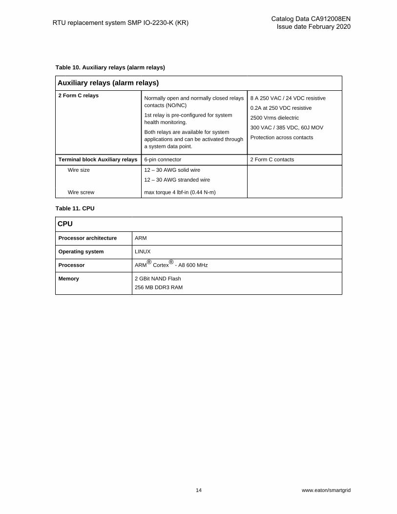
Table 10. Auxiliary relays (alarm relays)
Auxiliary relays (alarm relays)
2 Form C relays Normally open and normally closed relayscontacts (NO/NC)
1st relay is pre-configured for systemhealth monitoring.
Both relays are available for systemapplications and can be activated througha system data point.
8 A 250 VAC / 24 VDC resistive
0.2A at 250 VDC resistive
2500 Vrms dielectric
300 VAC / 385 VDC, 60J MOV
Protection across contacts
Terminal block Auxiliary relays 6-pin connector 2 Form C contacts
Wire size 12 – 30 AWG solid wire
12 – 30 AWG stranded wire
Wire screw max torque 4 lbf-in (0.44 N-m)
Table 11. CPU
CPU
Processor architecture ARM
Operating system LINUX
Processor ARM® Cortex® - A8 600 MHz
Memory 2 GBit NAND Flash
256 MB DDR3 RAM
14 www.eaton/smartgrid

Catalog Data CA912008ENIssue date February 2020 RTU replacement system SMP IO-2230-K (KR)
Table 12. Binary output (relays)
Binary outputs, relays (control outputs)
Output relays Form C relays (32) and Form A relays(depending on the control output mode)
Protection 1000 Vrms dielectric
300 VAC/ 385 VDC, 60J MOV protectionacross contact pairs
Operating time Pickup 10 ms maximum
Dropout 6 ms maximum
Rating
3A at 24 VDC resistive
3A at 250 VAC resistive
3A at 30 VDC resistive
0.4A at 125 VDC resistive
0.2A at 250 VDC resistive
3A at 250 VAC cos# 0.7
½ HP at 250 VAC, 1/3 HP at 125 VAC
All relay types
Rated insulation voltage 250 Vrms All relay types
Maximum voltage 400 VAC / 250 VDC All relay types
Minimum load 10 mA at 5 VDC All relay types
Cycling capacity (1 cycle/second) per IEC 60255-0-20:1974
24 VDC / 0.8A L/R= 40 ms
48 VDC / 0.5A L/R= 40 ms
125 VDC / 0.3A L/R= 40 ms
All relay types
Breaking capacity (10 000 operations) per IEC 60255-0-20:1974
24 VDC / 0.8A L/R= 40 ms
48 VDC / 0.5A L/R= 40 ms
125 VDC / 0.3A L/R= 40 ms
All relay types
Terminal Block Binary Output
Wire size 12 – 30 AWG solid wire
Wire screw maximum torque 4 lbf-in (0.44 N-m)
External fuse for wetting2 x 2A TL fuse for the KR model
1 x 2A TL fuse for the K model
Serviceable (accessible on the frontof the device)
www.eaton/smartgrid 15
RTU replacement system SMP IO-2230-K (KR) Catalog Data CA912008ENIssue date February 2020
Certifications and compliancy notesThe SMP IO-2230 platform, which is inserted into the chassis, is substation-grade and comply to severalstandards, refer to the SMP IO-2230 platform Catalog Data (CA912004EN) for details. The chassis itself didnot undergo tests for substation-grade compliancy.
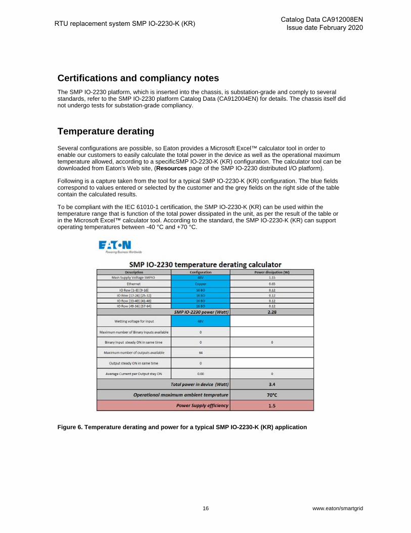
Temperature derating
Several configurations are possible, so Eaton provides a Microsoft Excel™ calculator tool in order toenable our customers to easily calculate the total power in the device as well as the operational maximumtemperature allowed, according to a specificSMP IO-2230-K (KR) configuration. The calculator tool can bedownloaded from Eaton's Web site, (Resources page of the SMP IO-2230 distributed I/O platform).
Following is a capture taken from the tool for a typical SMP IO-2230-K (KR) configuration. The blue fieldscorrespond to values entered or selected by the customer and the grey fields on the right side of the tablecontain the calculated results.
To be compliant with the IEC 61010-1 certification, the SMP IO-2230-K (KR) can be used within thetemperature range that is function of the total power dissipated in the unit, as per the result of the table orin the Microsoft Excel™ calculator tool. According to the standard, the SMP IO-2230-K (KR) can supportoperating temperatures between -40 °C and +70 °C.
Figure 6. Temperature derating and power for a typical SMP IO-2230-K (KR) application
16 www.eaton/smartgrid

Catalog Data CA912008ENIssue date February 2020 RTU replacement system SMP IO-2230-K (KR)
Dimension drawingsFollowing are the top and side views for the SMP IO-2230-K (KR).
Figure 7. Front view
Figure 8. Side view
www.eaton/smartgrid 17
RTU replacement system SMP IO-2230-K (KR) Catalog Data CA912008ENIssue date February 2020
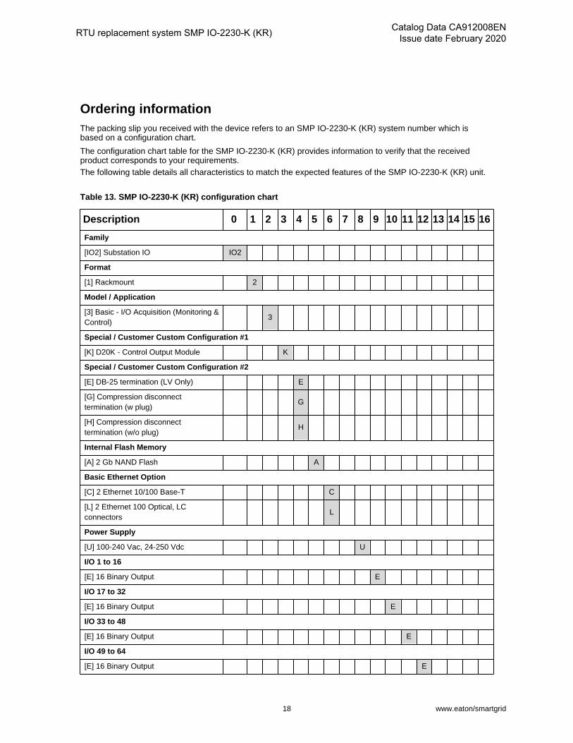
Ordering informationThe packing slip you received with the device refers to an SMP IO-2230-K (KR) system number which isbased on a configuration chart.
The configuration chart table for the SMP IO-2230-K (KR) provides information to verify that the receivedproduct corresponds to your requirements.The following table details all characteristics to match the expected features of the SMP IO-2230-K (KR) unit.
Table 13. SMP IO-2230-K (KR) configuration chart
Description 0 1 2 3 4 5 6 7 8 9 10 11 12 13 14 15 16
Family
[IO2] Substation IO IO2
Format
[1] Rackmount 2
Model / Application
[3] Basic - I/O Acquisition (Monitoring &Control)
3
Special / Customer Custom Configuration #1
[K] D20K - Control Output Module K
Special / Customer Custom Configuration #2
[E] DB-25 termination (LV Only) E
[G] Compression disconnecttermination (w plug)
G
[H] Compression disconnecttermination (w/o plug)
H
Internal Flash Memory
[A] 2 Gb NAND Flash A
Basic Ethernet Option
[C] 2 Ethernet 10/100 Base-T C
[L] 2 Ethernet 100 Optical, LCconnectors
L
Power Supply
[U] 100-240 Vac, 24-250 Vdc U
I/O 1 to 16
[E] 16 Binary Output E
I/O 17 to 32
[E] 16 Binary Output E
I/O 33 to 48
[E] 16 Binary Output E
I/O 49 to 64
[E] 16 Binary Output E
18 www.eaton/smartgrid

Catalog Data CA912008ENIssue date February 2020 RTU replacement system SMP IO-2230-K (KR)
Description 0 1 2 3 4 5 6 7 8 9 10 11 12 13 14 15 16
Internal - Analog Input Mode
[0] None 0
Internal - Wetting
[0] None / External Wetting Only 0
Internal - BI configuration
[0] None 0
Software package option
[0] SMP IO-2200 Basic profile / NONE 0
[A] SMP IO-2200 61850 profile A
Accessories and cables
Table 14. Accessories
Part number Description
SMP-BOM-0001 (Set of 32) Binary Output Module: Configuration Adaptor
SMP-BOM-0001 (Set of 16) Binary Output Module: Configuration Adaptor
SMP-PSU-2001 External Wetting Power supply: IN: 48VDC; OUT: 24 VDC
SMP-PSU-2002 External Wetting Power supply: IN: Univ. 125V; OUT: 24 VDC
Table 15. Cables
Part number Description
Shielded Power Cable
P-CABC-0303-00 AC Power Cable Shielded Nema 5-15-Wire
Important: Must be used for Demo or laboratory only
P-CABC-0306-00 Power Cable Shielded Wire-Wire 1.8m
P-CABC-0318-10 Power Cable Shielded Wire-Wire 10m
P-CABC-0318-03 Power Cable Shielded Wire-Wire 3m
P-CABC-0318-01 Power Cable Shielded Wire-Wire 1m
P-CABC-0318-xx Power Cable Shielded Wire-Wire xm
USB cable
600AB0008R Replacement USB Cable, Shielded
Note: For USB Console Port
www.eaton/smartgrid 19

RTU replacement system SMP IO-2230-K (KR) Catalog Data CA912008ENIssue date February 2020
Part number Description
Ethernet Multimode Fiber
-LC-LC
P-CABC-0315-0050 Multimode Fiber OM1 62.5/125um LC-LC 50m
P-CABC-0315-0025 Multimode Fiber OM1 62.5/125um LC-LC 25m
P-CABC-0315-0010 Multimode Fiber OM1 62.5/125um LC-LC 10m
P-CABC-0315-0003 Multimode Fiber OM1 62.5/125um LC-LC 3m
P-CABC-0315-0001 Multimode Fiber OM1 62.5/125um LC-LC 1m
P-CABC-0315-xxxx Multimode Fiber OM1 62.5/125um LC-LC xm
-ST-LC
P-CABC-0316-0050 Multimode Fiber OM1 62.5/125um LC-LC 50m
P-CABC-0316-0025 Multimode Fiber OM1 62.5/125um LC-LC 25m
P-CABC-0316-0010 Multimode Fiber OM1 62.5/125um LC-LC 10m
P-CABC-0316-0003 Multimode Fiber OM1 62.5/125um LC-LC 3m
P-CABC-0316-0001 Multimode Fiber OM1 62.5/125um LC-LC 1m
P-CABC-0316-xxxx Multimode Fiber OM1 62.5/125um LC-LC xm
Ethernet RJ45 Shielded cable
P-CABC-0310-025 Copper Ethernet Cable RJ45 CAT6 25m
P-CABC-0310-010 Copper Ethernet Cable RJ45 CAT6 10m
P-CABC-0310-03 Copper Ethernet Cable RJ45 CAT6 3m
P-CABC-0310-01 Copper Ethernet Cable RJ45 CAT6 1m
P-CABC-0310-xxx Copper Ethernet Cable RJ45 CAT6 xm
DB9 Serial Shielded Cable
RS-485 2-wires + IRIG-B, shielded cable, DB9 to Wires
P-CABC-0309-0010 RS485 2-wires Serial Cable DB9M to Wire 10m
P-CABC-0309-0003 RS485 2-wires Serial Cable DB9M to Wire 3m
P-CABC-0309-0001 RS485 2-wires Serial Cable DB9M to Wire 1m
P-CABC-0309-xxxx RS485 2-wires Serial Cable DB9M to Wire xm
Time Synchronization Shielded Cable
4 Twisted Pairs Shielded cable: Irig-B; RS-485 4-Wires/2-Wires Wire-Wire
P-CABC-0320-25 4 Twisted Pairs Cable Wire-Wire 25 m
P-CABC-0320-10 4 Twisted Pairs Cable Wire-Wire 10 m
P-CABC-0320-03 4 Twisted Pairs Cable Wire-Wire 3 m
P-CABC-0320-01 4 Twisted Pairs Cable Wire-Wire 1 m
P-CABC-0320-xx 4 Twisted Pairs Cable Wire-Wire xm
Some cables can be provided with custom lengths, according to customer request. For a custom length-cable,use the required length to create your own cable code.
20 www.eaton/smartgrid

Catalog Data CA912008ENIssue date February 2020 RTU replacement system SMP IO-2230-K (KR)
Contact your Eaton representative to validate the maximum length for your application. Example: a cable P-CABC-0310-xxx with 2 meters length will be P-CABC-0310-002 (always use length in meters). Contact Eatonfor other cable requirements.
www.eaton/smartgrid 21

Eaton1000 Eaton BoulevardCleveland, OH 44122United StatesEaton.com
Eaton’s Power Systems Division2300 Badger DriveWaukesha, WI 53188United StatesEaton.com/smartgrid
© 2020 EatonAll Rights ReservedPrinted in USAPublication No. CA912008EN
Eaton is a registered trademark.
All other trademarks are property of their respective owners.
To learn more, visit
Eaton.com/smartgrid
Follow us on social media to get the latest product and support information.