Embed Size (px)
Citation preview
Draft 10-12-12
i
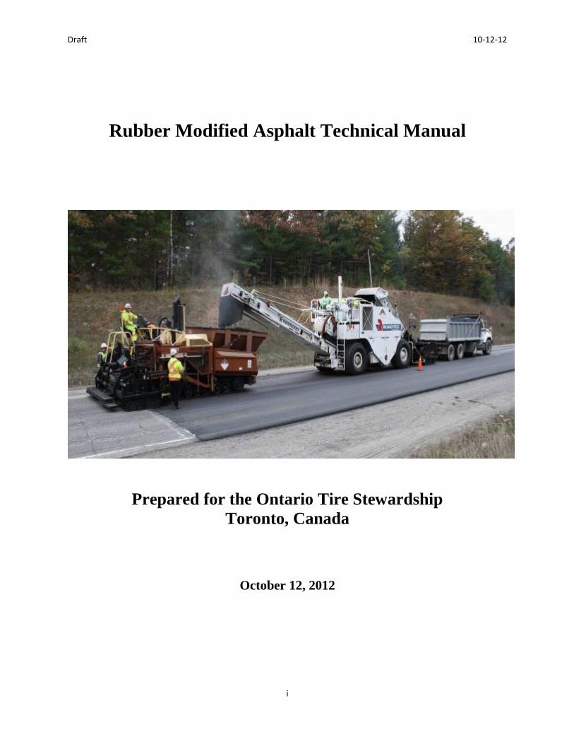
Rubber Modified Asphalt Technical Manual
Prepared for the Ontario Tire Stewardship
Toronto, Canada
October 12, 2012

Draft 10-12-12
ii
PROJECT SUMMARY PAGE Date: Oct 12, 2012
Title: Rubber Modified Asphalt Technical Manual
Authors: R. Gary Hicks, Susan Tighe, and DingXin Cheng
Prepared For:
Ontario Tire Stewardship Client Reference No.:
Abstract:
Rubber modified asphalt including asphalt rubber and terminal blend has been widely used in
many countries. In order to promote sustainability and utilize recycled waste tires, Ontario Tire
Stewardship would like to develop a comprehensive technical manual to support the technology
transfer of utilizing rubber modified asphalt in Ontario, Canada.
This manual contains the knowledge and practices of various experienced agencies around the
world, as well as Ontario’s local experiences of utilizing crumb rubber in pavement. An
international survey was conducted and its results were utilized in this manual. A specification
report combining the knowledge around the world was generated and recommendations were
provided for Ontario. The manual also includes the knowledge from recent field trials by the
Ministry of Transportation, Ontario, and laboratory testing on rubberized asphalt cement.
This manual was developed to provide guidance to agencies, contractors and consulting
engineers in Ontario who are using or plan to use crumb rubber modifier (CRM) in hot mix
asphalt, chip seals, or interlayers. The major contents of the manual include an introduction and
definitions of CRM and rubber modified asphalt, various applications and a guide for using
rubberized asphalt cement, design and specification guidelines, production and construction
considerations of rubber modified asphalt, inspections of rubber modified asphalt paving
projects, and a summary of key points for successfully implementing the rubber modified asphalt
concrete.
Keywords: Ground Tire Rubber, Asphalt Rubber, Terminal Blend, Rubber Modified Asphalt,
Chip Seals and Interlayers

Draft 10-12-12
iii
Foreword
The Ontario Ministry of Transportation (MTO) has experimented with rubber modified asphalt for several
years. The rubberized binders have been used in both gap- and dense-graded mixes. In gap-graded mixes,
the product known as asphalt rubber has been used. This product requires the use of specialized blending
equipment to react the binder. Terminal blend rubber modified binders have been used in dense-graded
mixes. The product is produced at a terminal where the fine crumb rubber is blended into the asphalt
forming a product similar to polymer modified asphalt. Specifications for both products are now available
from the MTO.
The Ontario Tire Stewardship (OTS) is working with industry and agencies to increase the use of recycled
tires in asphalt pavements. They have been working closely with the MTO to place pilot projects
throughout the Province and to increase the awareness of the benefits of using recycled tires in the
pavement. New tire processors have been installed in Ontario to help recycle Ontario’s tire population.
The Province is now positioned to use rubberized asphalt products in many of their roads.
This manual was developed for use by agencies, contractors and consulting engineers in Ontario who plan
on using crumb rubber modifier (CRM) in hot mix asphalt, chip seals, or interlayers. This manual has
been developed by Dr. Susan Tighe (Consultant), Dr. Gary Hicks (Consultant), and Dr. DingXin Cheng
for the Ontario Tire Stewardship in Toronto, Canada. The manual consists of the following chapters:
Chapter 1. Introduction to Rubber Modified Asphalt
Chapter 2. Application and Usage Guide for Asphalt Rubber Cement
Chapter 3. Design and Specification Guide
Chapter 4. Production and Construction Considerations
Chapter 5. Inspection Guide
Chapter 6. Summary of Key Points
In addition, it contains several appendices which include:
Appendix A. Glossary
Appendix B. Summary of survey
Appendix C. Specifications for asphalt rubber field blends and terminal blends
Appendix D. Mix design procedures for rubberized asphalt mixes
Appendix E. Project experiences with 2011 rubberized asphalt mixes
Appendix F. Crumb rubber sample examination performed by the MTO
Copies of the manual can be obtained from:
Andrew Horsman, Executive Director
Ontario Tire Stewardship
Toronto, Ontario
416-626-9185
www.ontariots.com
Draft 10-12-12
iv
Acknowledgements
We appreciate the financial support of Andrew Horsman, of the Ontario Tire Stewardship, for
providing the funding for this important and meaningful project. We also appreciate the technical
support from Seyed Tabib of the Ministry of Transportation Ontario (MTO) as well as that of
Simon Hesp, professor of chemistry at the Queen’s University of Kingston. In addition, we
appreciate the support of Bob Fujii and Nate Gauff of CalRecycle who allowed us to modify
their documents (RAC 101 to RAC 105) for use in this technical manual. The information has
been modified to reflect the practices in Canada.
Disclaimer
The contents of this report reflect the views of the authors who are responsible for the facts and
accuracy of the data presented herein. The contents do not necessarily reflect the official views
or policies of the Ontario Tire Stewardship or the Ontario Ministry of Transportation.

Draft 10-12-12
v
TABLE OF CONTENTS
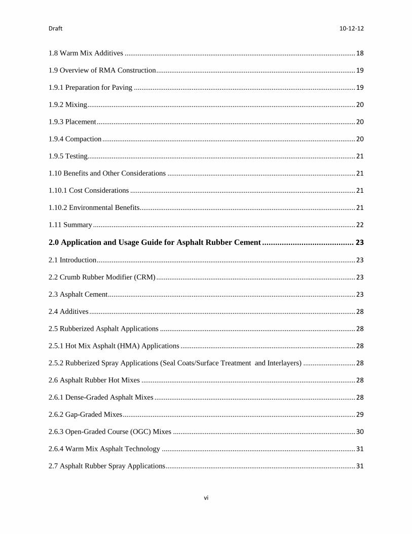
1.0 Introduction to Rubber Modified Asphalt ...................................................................... 1
1.1 Introduction ............................................................................................................................................. 1
1.2 Rubber Modified Cement Types ............................................................................................................. 1
1.2.1 Wet Process – High Viscosity (Asphalt rubber) .................................................................................. 2
1.2.2 Wet Process – No Agitation (Terminal Blends) .................................................................................. 3
1.2.3 Dry Process .......................................................................................................................................... 3
1.3 Asphalt Rubber Cement Components ..................................................................................................... 4
1.3.1 Crumb Rubber Modifier ...................................................................................................................... 4
1.3.2 Asphalt Cements .................................................................................................................................. 5
1.3.3 Additives .............................................................................................................................................. 7
1.4 History of Asphalt Rubber ...................................................................................................................... 8
1.4.1 International History and Experience .................................................................................................. 8
1.4.2 Canadian History ................................................................................................................................. 9
1.5 Types of Applications ........................................................................................................................... 12
1.5.1 Chip Seals .......................................................................................................................................... 13
1.5.2 Interlayers .......................................................................................................................................... 14
1.5.3 Hot Mix Asphalt ................................................................................................................................ 14
1.6 Overview of Asphalt Rubber Binder Production .................................................................................. 15
1.6.1 Holdover and Preheating Issues ......................................................................................................... 16
1.6.2 Required Documentation ................................................................................................................... 16
1.6.3 Sampling and Testing ........................................................................................................................ 17
1.7 Terminal Blends .................................................................................................................................... 18
1.7.1 Required Documentation ................................................................................................................... 18
Draft 10-12-12
vi
1.8 Warm Mix Additives ............................................................................................................................ 18
1.9 Overview of RMA Construction ........................................................................................................... 19
1.9.1 Preparation for Paving ....................................................................................................................... 19
1.9.2 Mixing ................................................................................................................................................ 20
1.9.3 Placement ........................................................................................................................................... 20
1.9.4 Compaction ........................................................................................................................................ 20
1.9.5 Testing................................................................................................................................................ 21
1.10 Benefits and Other Considerations ..................................................................................................... 21
1.10.1 Cost Considerations ......................................................................................................................... 21
1.10.2 Environmental Benefits.................................................................................................................... 21
1.11 Summary ............................................................................................................................................. 22
2.0 Application and Usage Guide for Asphalt Rubber Cement .......................................... 23
2.1 Introduction ........................................................................................................................................... 23
2.2 Crumb Rubber Modifier (CRM) ........................................................................................................... 23
2.3 Asphalt Cement ..................................................................................................................................... 23
2.4 Additives ............................................................................................................................................... 28
2.5 Rubberized Asphalt Applications ......................................................................................................... 28
2.5.1 Hot Mix Asphalt (HMA) Applications .............................................................................................. 28
2.5.2 Rubberized Spray Applications (Seal Coats/Surface Treatment and Interlayers) ............................ 28
2.6 Asphalt Rubber Hot Mixes ................................................................................................................... 28
2.6.1 Dense-Graded Asphalt Mixes ............................................................................................................ 28
2.6.2 Gap-Graded Mixes ............................................................................................................................. 29
2.6.3 Open-Graded Course (OGC) Mixes .................................................................................................. 30
2.6.4 Warm Mix Asphalt Technology ........................................................................................................ 31
2.7 Asphalt Rubber Spray Applications ...................................................................................................... 31

Draft 10-12-12
vii
2.7.1 Chip Seal Construction Process ......................................................................................................... 31
2.7.2 Chip Seal Equipment ......................................................................................................................... 32
2.7.3 Asphalt Rubber Spray Application .................................................................................................... 32
2.7.4 Aggregate Application ....................................................................................................................... 33
2.7.5 Rolling Asphalt Rubber Chip Seals ................................................................................................... 33
2.7.6 Sweeping ............................................................................................................................................ 34
2.7.7 Flush Coat or Fog Seal ....................................................................................................................... 34
2.7.8. Sand Cover ........................................................................................................................................ 34
2.7.9 Traffic Control ................................................................................................................................... 35
2.8 Summary ............................................................................................................................................... 35
3.0 Design and Specification Guide .................................................................................... 36
3.1 Design Guides ....................................................................................................................................... 36
3.1.1 Publication Guide Resources ............................................................................................................. 36
3.1.2 Where and Why Use Rubber Modified Asphalt? .............................................................................. 36
3.1.3 Tests for Asphalt Rubber ................................................................................................................... 36
3.1.4 Tests for Terminal Blends .................................................................................................................. 38
3.2 Behavior of Rubberized Asphalt Concrete (RAC) Hot Mixes .............................................................. 39
3.2.1 Mix Properties .................................................................................................................................... 40
Binder profile .............................................................................................................................................. 40
3.2.2 Factors Affecting Performance .......................................................................................................... 40
3.3 Structural Design .................................................................................................................................. 40
3.4 Selection of Mix Types ......................................................................................................................... 41
3.5 RMA Mix Design ................................................................................................................................. 42
3.5.1 Wet Process High Viscosity ............................................................................................................... 43
3.5.2 Wet Process No Agitation (Terminal Blends) ................................................................................... 43
Draft 10-12-12
viii
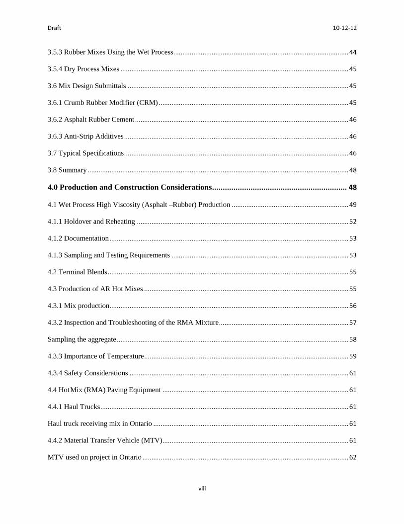
3.5.3 Rubber Mixes Using the Wet Process ................................................................................................ 44
3.5.4 Dry Process Mixes ............................................................................................................................. 45
3.6 Mix Design Submittals ......................................................................................................................... 45
3.6.1 Crumb Rubber Modifier (CRM) ........................................................................................................ 45
3.6.2 Asphalt Rubber Cement ..................................................................................................................... 46
3.6.3 Anti-Strip Additives ........................................................................................................................... 46
3.7 Typical Specifications ........................................................................................................................... 46
3.8 Summary ............................................................................................................................................... 48
4.0 Production and Construction Considerations ............................................................... 48
4.1 Wet Process High Viscosity (Asphalt –Rubber) Production ................................................................ 49
4.1.1 Holdover and Reheating .................................................................................................................... 52
4.1.2 Documentation ................................................................................................................................... 53
4.1.3 Sampling and Testing Requirements ................................................................................................. 53
4.2 Terminal Blends .................................................................................................................................... 55
4.3 Production of AR Hot Mixes ................................................................................................................ 55
4.3.1 Mix production ................................................................................................................................... 56
4.3.2 Inspection and Troubleshooting of the RMA Mixture ....................................................................... 57
Sampling the aggregate ............................................................................................................................... 58
4.3.3 Importance of Temperature ................................................................................................................ 59
4.3.4 Safety Considerations ........................................................................................................................ 61
4.4 Hot Mix (RMA) Paving Equipment ...................................................................................................... 61
4.4.1 Haul Trucks ........................................................................................................................................ 61
Haul truck receiving mix in Ontario ........................................................................................................... 61
4.4.2 Material Transfer Vehicle (MTV) ...................................................................................................... 61
MTV used on project in Ontario ................................................................................................................. 62
Draft 10-12-12
ix
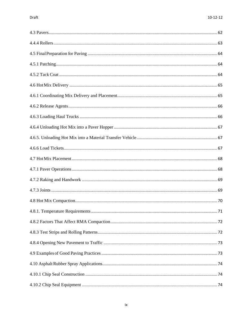
4.3 Pavers .................................................................................................................................................... 62
4.4.4 Rollers ................................................................................................................................................ 63
4.5 Final Preparation for Paving .................................................................................................................. 64
4.5.1 Patching.............................................................................................................................................. 64
4.5.2 Tack Coat ........................................................................................................................................... 64
4.6 Hot Mix Delivery .................................................................................................................................. 65
4.6.1 Coordinating Mix Delivery and Placement........................................................................................ 65
4.6.2 Release Agents ................................................................................................................................... 66
4.6.3 Loading Haul Trucks ......................................................................................................................... 66
4.6.4 Unloading Hot Mix into a Paver Hopper ........................................................................................... 67
4.6.5. Unloading Hot Mix into a Material Transfer Vehicle ....................................................................... 67
4.6.6 Load Tickets ....................................................................................................................................... 67
4.7 Hot Mix Placement ................................................................................................................................ 68
4.7.1 Paver Operations ................................................................................................................................ 68
4.7.2 Raking and Handwork ....................................................................................................................... 69
4.7.3 Joints .................................................................................................................................................. 69
4.8 Hot Mix Compaction............................................................................................................................. 70
4.8.1. Temperature Requirements ............................................................................................................... 71
4.8.2 Factors That Affect RMA Compaction .............................................................................................. 72
4.8.3 Test Strips and Rolling Patterns ......................................................................................................... 72
4.8.4 Opening New Pavement to Traffic .................................................................................................... 73
4.9 Examples of Good Paving Practices ...................................................................................................... 73
4.10 Asphalt Rubber Spray Applications ..................................................................................................... 74
4.10.1 Chip Seal Construction .................................................................................................................... 74
4.10.2 Chip Seal Equipment ....................................................................................................................... 74

Draft 10-12-12
x
4.10.3 Asphalt Rubber Spray Application .................................................................................................. 75
4.10.4 Aggregate Application ..................................................................................................................... 76
4.10.5 Rolling Asphalt Rubber Chip Seals ................................................................................................. 77
4.10.6 Sweeping .......................................................................................................................................... 77
4.10.7 Flush Coat or Fog Seal ..................................................................................................................... 78
4.10.8 Sand Cover ....................................................................................................................................... 78
4.10.9 Traffic Control ................................................................................................................................. 78
4.11 Emissions ............................................................................................................................................ 79
4.11.1 Air Quality ....................................................................................................................................... 79
4.11.2 FHWA/USEPA Studies ................................................................................................................... 79
4.11.3 AC Plant Emissions Tests ................................................................................................................ 79
4.11.4 Worker Health and Safety ................................................................................................................ 80
4.11.5 National Institute for Occupational Safety and Health (NIOSH) .................................................... 81
4.11.6 Industry Studies in California .......................................................................................................... 81
4.11.7 Worker Exposure ............................................................................................................................. 81
4.11.8 Water Quality ................................................................................................................................... 82
4.12 Summary ........................................................................................................................................... 82
5.0 Inspection Guide for Rubberized Asphalt Operations................................................... 83
5.1 Introduction ........................................................................................................................................... 83
5.1.1 Purpose ............................................................................................................................................... 83
5.1.2 Advantages of RMA .......................................................................................................................... 84
5.2 Inspection of RMA Production ............................................................................................................ 84
5.2.1 Wet Process High Viscosity (Asphalt Rubber) .................................................................................. 85
5.2.2 Wet Process no agitation (Terminal Blends) ..................................................................................... 85
5.2.3 Dry Process ........................................................................................................................................ 85
Draft 10-12-12
xi
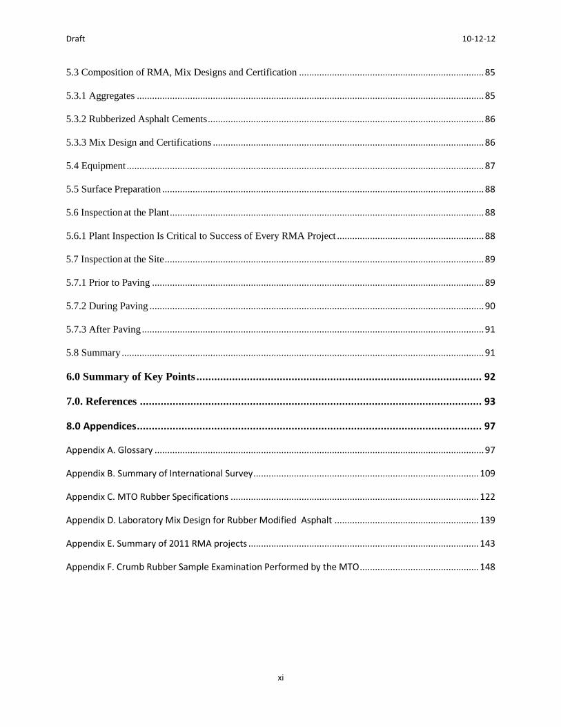
5.3 Composition of RMA, Mix Designs and Certification ......................................................................... 85
5.3.1 Aggregates ......................................................................................................................................... 85
5.3.2 Rubberized Asphalt Cements ............................................................................................................. 86
5.3.3 Mix Design and Certifications ........................................................................................................... 86
5.4 Equipment ............................................................................................................................................. 87
5.5 Surface Preparation ............................................................................................................................... 88
5.6 Inspection at the Plant ............................................................................................................................ 88
5.6.1 Plant Inspection Is Critical to Success of Every RMA Project .......................................................... 88
5.7 Inspection at the Site .............................................................................................................................. 89
5.7.1 Prior to Paving ................................................................................................................................... 89
5.7.2 During Paving .................................................................................................................................... 90
5.7.3 After Paving ....................................................................................................................................... 91
5.8 Summary ............................................................................................................................................... 91
6.0 Summary of Key Points ................................................................................................ 92
7.0. References ................................................................................................................... 93
8.0 Appendices .................................................................................................................... 97
Appendix A. Glossary .................................................................................................................................. 97
Appendix B. Summary of International Survey ......................................................................................... 109
Appendix C. MTO Rubber Specifications .................................................................................................. 122
Appendix D. Laboratory Mix Design for Rubber Modified Asphalt ......................................................... 139
Appendix E. Summary of 2011 RMA projects ........................................................................................... 143
Appendix F. Crumb Rubber Sample Examination Performed by the MTO ............................................... 148

Draft 10-12-12
1
1.0 Introduction to Rubber Modified Asphalt
1.1 Introduction
This guide is a comprehensive resource for the usage of rubber modified asphalt (RMA) in
Canada. Various material, design and construction aspects of RMA are presented herein with an
emphasis on Canadian specifications and best practices. RMA usage is of interest to many
Canadian transportation agencies based on the potential technical, economic and environmental
benefits. Furthermore, as resources, namely aggregate and asphalt cement, become scarcer and
more expensive, the opportunity to reuse rubber tires in asphalt pavements becomes even more
attractive. The ability to reuse the crumb rubber in an engineered manner not only provides
technical benefits but also potential environmental savings.
RMA can be incorporated into Hot Mix Asphalt (HMA) and placed using conventional asphalt
equipment and procedures. Some slight modifications may be required and these are further
discussed in this document. However, these modifications can be easily accommodated with
proper training and inspection. The RMA pavements can be designed in the same manner as
conventional HMA and would be expected to provide similar structural numbers. As long as
quality is achieved, there should be little change in the performance of the RMA in the field as
compared to conventional HMA. In fact, experiences in California, Texas and Arizona have
shown that performance of these mixes is superior. In Canada, performance has not been
historically as good; however, with proper material testing, RMA should show similar
performance to that observed in the United States. This manual provides design and construction
guidelines for the construction of quality RMA pavements with long lasting performance.
1.2 Rubber Modified Cement Types
The inclusion of crumb rubber in asphalt concrete mixes is done by either a wet or dry process.
The wet process develops a range of rubber modified binders from a high viscosity type to no
agitation types. There are three types of RMA and these are dependent on the process in which
they are mixed into the HMA. The first type is a wet process-high viscosity which involves
mixing, while the second type is also a wet process with no mixing. Finally the third type is a
dry process. All three types are described below.
The crumb rubber can be produced either through ambient grinding, cryogenic grinding, or a
combination of the two. Definitions for the types of processing are given in Appendix A. The
type of processing can have an effect on the performance of the paving mixture as will be
discussed later in the manual.

Draft 10-12-12
2
1.2.1 Wet Process – High Viscosity (Asphalt rubber)
The wet process or field-blended asphalt rubber incorporates the crumb rubber modifier (CRM)
directly into the asphalt cement (AC) before it is mixed into the RMA. When the CRM is mixed
into the hot asphalt cement, it must be maintained between 205 and 220oC. Once the mixing
process is complete, the CRM-AC blend should be maintained between 165 and 220oC for at
least 45 minutes to one hour. This is important to ensure the CRM-AC blend is completely
mixed. During this time, other extenders, asphalt modifiers and/or high natural CRM may be
added depending on the specific material requirements for the pavement. It is also important to
note that during the mixing of the CRM-AC, the CRM will swell and various chemical reactions
may occur. When the material is stable, it is then ready for addition to the HMA. Typically, the
high viscosity type of asphalt rubber contains approximately 18-22% crumb rubber, with particle
sizes of 2.00 mm (Sieve No. 10) to 2.36 mm (Sieve No. 8). The wet process or field-blended
asphalt rubber is typically used in gap- or open- graded mixes and chip seal applications.
Photo of Crumb rubber used in asphalt rubber in California
Photo of Crumb rubber used in Ontario
Draft 10-12-12
3
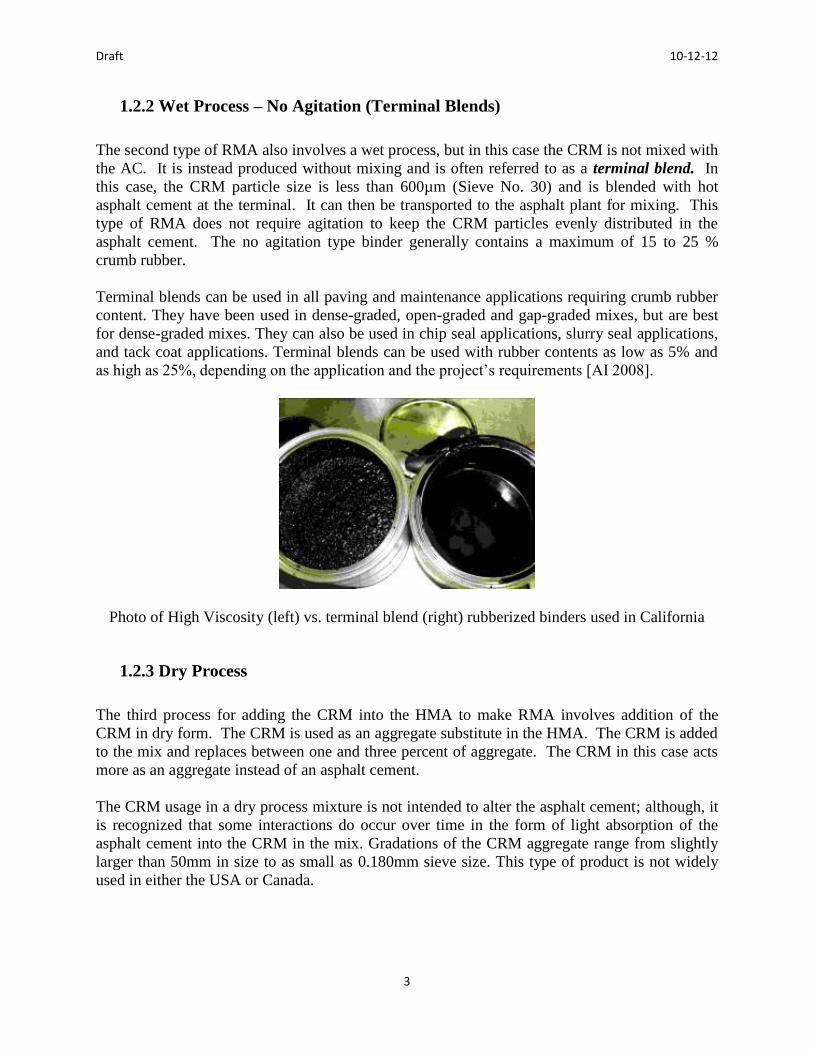
1.2.2 Wet Process – No Agitation (Terminal Blends)
The second type of RMA also involves a wet process, but in this case the CRM is not mixed with
the AC. It is instead produced without mixing and is often referred to as a terminal blend. In
this case, the CRM particle size is less than 600µm (Sieve No. 30) and is blended with hot
asphalt cement at the terminal. It can then be transported to the asphalt plant for mixing. This
type of RMA does not require agitation to keep the CRM particles evenly distributed in the
asphalt cement. The no agitation type binder generally contains a maximum of 15 to 25 %
crumb rubber.
Terminal blends can be used in all paving and maintenance applications requiring crumb rubber
content. They have been used in dense-graded, open-graded and gap-graded mixes, but are best
for dense-graded mixes. They can also be used in chip seal applications, slurry seal applications,
and tack coat applications. Terminal blends can be used with rubber contents as low as 5% and
as high as 25%, depending on the application and the project’s requirements [AI 2008].
Photo of High Viscosity (left) vs. terminal blend (right) rubberized binders used in California
1.2.3 Dry Process
The third process for adding the CRM into the HMA to make RMA involves addition of the
CRM in dry form. The CRM is used as an aggregate substitute in the HMA. The CRM is added
to the mix and replaces between one and three percent of aggregate. The CRM in this case acts
more as an aggregate instead of an asphalt cement.
The CRM usage in a dry process mixture is not intended to alter the asphalt cement; although, it
is recognized that some interactions do occur over time in the form of light absorption of the
asphalt cement into the CRM in the mix. Gradations of the CRM aggregate range from slightly
larger than 50mm in size to as small as 0.180mm sieve size. This type of product is not widely
used in either the USA or Canada.

Draft 10-12-12
4
1.3 Asphalt Rubber Cement Components
The materials and their respective proportions are determined in accordance with the local
specifications. The asphalt rubber binder must meet all of the asphalt specifications for the
intended pavement design.
1.3.1 Crumb Rubber Modifier
Crumb rubber modifier (CRM) is composed of ground scrap tires, tread buffing and other waste
or excess rubber products. Currently, there are a number of available processes and equipment
used to produce the required gradations of CRM material to be used in RMA. The list of current
CRM suppliers in Ontario is provided below:
Liberty Tire Recycling
Contact: Jeff Bateman
Phone: 1-519-752-7696 / 1-800-387-8473 (mobile: 1-519-590-7070)
E-mail: [email protected]
Website: www.libertytire.com
Location: 300 Henry Street, Brantford, Ontario
CRM Co ULC
Contact: Christie Newmeyer
Phone: 949.263.9100 (mobile: 949.529.6444)
E-mail: [email protected]
Website: www.crmrubber.com
Location: 150 Garden Ave, Brantford, Ontario
Draft 10-12-12
5
For additional information on crumb rubber suppliers, please contact:
Andrew Horsman, Executive Director
Ontario Tire Stewardship
(o) 416-626-9185
(m) 416-428-7702
1.3.2 Asphalt Cements
Asphalt cement specifications are well established in Canadian transportation agencies and
industry suppliers are very experienced with meeting the required quality parameters for use in
asphalt pavement. Conventional asphalt specifications were developed to define physical
properties such as penetration, viscosity and ductility. A criticism of these conventional physical
property tests was that they were performed at standard temperatures, regardless of the
environmental characteristics of the intended area of use. In an effort to address the shortcomings
of the traditional conventional asphalt grading subsystems, such as ASTM and AASHTO, the
Strategic Highway Research Program (SHRP) in the United States and the Canadian counterpart
(C-SHRP) undertook, as a primary objective, the development of performance based grading
specifications for asphalt cements [TAC 2012].
Testing protocols were developed to represent field performance. The resultant performance
grade asphalt cement (PGAC) specification classifies asphalt cements based on the temperature
environment for their intended use. Asphalt cements are performance graded and required to
comply with specified requirements at both the low and high pavement in-service temperatures
which must be determined on a project specific basis [AASHTO 2010, TAC 2012].
Draft 10-12-12
6
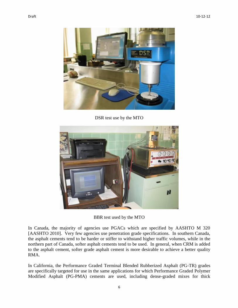
DSR test use by the MTO
BBR test used by the MTO
In Canada, the majority of agencies use PGACs which are specified by AASHTO M 320
[AASHTO 2010]. Very few agencies use penetration grade specifications. In southern Canada,
the asphalt cements tend to be harder or stiffer to withstand higher traffic volumes, while in the
northern part of Canada, softer asphalt cements tend to be used. In general, when CRM is added
to the asphalt cement, softer grade asphalt cement is more desirable to achieve a better quality
RMA.
In California, the Performance Graded Terminal Blended Rubberized Asphalt (PG-TR) grades
are specifically targeted for use in the same applications for which Performance Graded Polymer
Modified Asphalt (PG-PMA) cements are used, including dense-graded mixes for thick

Draft 10-12-12
7
structural sections [Caltrans 2008, AI 2008]. Typical terminal blended grades are PG64-28TR,
PG70-22TR, and PG76-22TR. These grades can have varying rubber contents from as low as 5%
to as high as 25% by weight. Caltrans, Nevada Department of Transportation (NDOT), and the
Pacific Coast Conference on Asphalt Specifications (PCCAS) have adopted the PG terminal
blends and have accepted them as an alternative to PMA materials. In 2008, Nevada DOT built a
six-mile project with PG64-28TR as a replacement for their PG64-28NV specification [AI
2008]. Several projects have been placed in California using this product for both chip seals and
in HMA.
In Canada, typical PG binders would include: PG 52-34 (northern, cold climate areas), PG 58-34
(moderate climate areas) and PG 58-28 (southern, warmer climate areas). It is important to note
that these grades are often bumped due to both higher traffic levels and static or slow moving
levels. This can result in PG 64-28 and/or possibly PG 70-28 for areas where there is extensive
truck traffic that is slow moving or stopped [OHMPA 1999]. When CRM is added to the asphalt
cement, it should meet the final PG grade specified for the pavement design. Thus, the base PG
asphalt cement prior to addition of rubber may be different from the final rubber asphalt PG.
One of the challenges with this is that the blended rubber materials, especially field blend, may
not be suitable for testing using the standard PG asphalt cement test such as the AASHTO M320
[AASHTO 2010].
1.3.3 Additives
Use of additives with the asphalt cement in HMA is often related to enhancing the mixture
workability and compatibility. Various modifiers have been developed, mainly to reduce the
temperature susceptibility of asphalt materials. This can be accomplished by improving the
critical stiffness properties of the asphalt cement at both the low and high service temperature
extremes. With the adoption of PGAC by most agencies in Canada, specific engineered asphalt
specifications are becoming obsolete as the PGAC specifications set the performance
requirements. Possible additives used with CRM can include: extender oils, high natural rubber
(HNR), polymers (mainly in no agitation binders) and/or mineral admixtures [Caltrans MTAG
2008].
Samples of high natural rubber and crumb tire rubber. The HNR is on the bottom

Draft 10-12-12
8
1.4 History of Asphalt Rubber
The earliest application of asphalt rubber was during the 1930s as a joint sealer, in patches and in
membranes. The effects of the application of rubber in asphaltic paving material were
investigated in the 1950s by the Bureau of Public Records of the State of California using a
number of different rubber powders and asphalt combinations. By the 1960s, the first symposium
on rubber in asphalt was held by the Asphalt Institute and included a number of paper
presentations and discussions on the innovative inclusion of rubber in asphalt paving material
[Sacramento 1999].
Photos of Caltrans projects placed in 1983 and taken in 1993. Pavement was placed in northeast
California in a cold dry climate where thermal cracking is prevalent.
1.4.1 International History and Experience
Since the 1960s, rubber material has been used by government jurisdictions mainly in chip seals,
interlayers and HMA. In the United States, it has been used in California, Arizona, Florida and
Texas. As noted, these states exhibit warmer climates. This usage has been documented and it
has been shown that RMA does provide noise reducing benefits [Sacramento 1999]. Since the
early days, its use has expanded to colder regions in the United States, China, and Scandinavia
[Cheng and Hicks, 2012]
Terminal blended asphalt rubber technology has been used since the mid-1980s in many states.
In the terminal blending of rubberized asphalt, tire rubber is blended into the asphalt cement at
the asphalt terminal or refinery and shipped to the hot mix production plant as a finished product
with no additional handling or processing. The tire rubber is completely digested into the asphalt
to provide styrene, butadiene, carbon black and aromatic oils yielding a homogeneous material
that exhibits excellent storage stability and compatibility with the finished binder formulation
[AI 2008]. This product is very similar to polymer modified asphalt cement.
Terminal blended rubberized asphalt (TR) was first used in Texas in the mid-1980s. It was
initially used in Texas and Louisiana in dense-graded hot mix. A modified, hot-applied chip seal
was adapted in Texas about the same time. Not long after, TR was used in open- and gap-graded

Draft 10-12-12
9
surface courses in Texas, Florida, Louisiana, New York, Arizona, California and Nevada [AI
2008]. The Wright process of terminal blending is used by many of these states.
In addition, in Belgium, research involving open-graded rubberized asphalt has also been shown
to reduce noise pollution at traffic speeds of 50km/h in the range of 2.1 to 3.2 dBA. Similar
studies have been conducted in the United States, France, Austria and Germany on the noise
reducing effect of rubberized asphalt concrete with similar results [Sacramento 1999].
1.4.2 Canadian History
Rubber modified asphalt has had limited application in Canada, though several agencies are in
the process of investigating the inclusion of RMA in current transportation infrastructure.
Ontario
The province of Ontario has over 30 years of experience with rubber asphalt projects. During
the first trials, between 1980 and 1995, the objectives included determining whether the addition
of scrap tires into asphalt was environmentally acceptable, identifying if rubber asphalt
pavements could be recycled, and determining rubberized asphalt’s economic feasibility. The
majority of these trials adopted a dry process mix, where the rubber is added as a portion of the
aggregate content. Performance of these test sections was generally moderate to poor [Tabib
2009]. One significant trial was built in two phases on Highway 2 in Thamesville, Ontario to
evaluate feasibility and performance of RMA [Lawrence 1991]. In Phase 1 of construction,
advances were made especially in the areas of worker safety, as the additional hazards of
working with rubber asphalt became understood [Lawrence 1991]. With the benefits of recycling
asphalt already known, and following the successful completion of Phase 1, the objective of
Phase 2 was to determine the recyclability of rubber asphalt pavements [Aurilio 1993]. The test
sections were successfully removed, recycled, and repaved. Results of the recycled pavement
were similar to the original results, with stone loss noted as the only major issue [Aurilio 1993].
A 1994 review of 11 Ontario rubber asphalt projects noted that roller pick up had been a serious
construction issue [Emery 1994].
A comparative study, conducted in 1995 examined the differences between moist-process
(similar to dry process, but using crumb rubber particles smaller than 600 m in size) and wet-
process asphalt mixes. A City of Brantford project was chosen as the representative moist
design. A 500 m test section was paved in Brantford in 1994. Initial testing determined that the
pavement performed acceptably in every area [Carrick 1995]. The Town of Kirkland project
was chosen as the wet-process representative. A 300 m test section was constructed in 1994.
No significant problems were noted and the project is considered a technical success [Carrick
1995]. However, the wet process mix was associated with an additional initial cost 40% greater
than the moist process mix [Carrick 1995].
Following these initial trials, the Ministry of the Environment (MOE) and the Ministry of
Transportation (MTO) sponsored a 1997 study to evaluate the performance of 15 test sections.
Visual inspections, distress surveys, deflection and frictional properties testing, and pavement

Draft 10-12-12
10
profile measurements were conducted [Tabib 2009]. The report from this project included
several key findings. First, sections constructed using the dry process generally performed worse
than sections constructed of conventional HMA, while sections constructed using the moist
process were somewhat comparable to conventional pavement sections. Wet-process test sites
exhibited superior performance to other rubber asphalt mixes, and were generally similar to
conventional pavements [Tabib 2009].
A continuum to the 1997 study was performed by the MTO in 2003, to evaluate the long-term
performance of rubber asphalt sections within the province. The 2003 survey collected
information on the current traffic volume, the date of resurfacing and the pavement condition
prior to resurfacing, as well as other general comments. The findings from this survey indicated
that many of the pavements had been resurfaced in 2003. However, due to limited information,
no firm conclusions could be drawn regarding performance [Tabib 2009].
The Regional Municipality of Waterloo (RMOW), Ontario, Canada, in partnership with the
University of Waterloo Centre for Pavement and Transportation Technology (CPATT),
investigated three types of noise reducing pavements: Rubberized Open Graded Friction Course
Asphalt Pavements (rOFC and rOGC) and Stone Mastic Asphalt Pavement (SMA). The two
types of open friction course asphalt pavements had a similar mix design, but were different in
the quality of the aggregate. Two types of field sound level measurements were conducted in
this study: Close-Proximity Method and Controlled Pass-By Method. Laboratory testing
including impedance tube testing was utilized to determine the pavement sound absorption
properties [Leung 2006]. The study found that vehicle noise increases when the vehicle speed or
size increases for both test methods. The SMA pavement type did not provide any noise
reductions for light sized vehicles and for vehicle speeds of 60 km/h and 70 km/h in both test
methods. rOFC and rOGC provide the highest amount of noise reduction in both testing
methods. The highest noise reduction amounts for rOFC and rOGC pavement were 3.3 dBA in
the CPX results. For the pass by method results, the highest noise reduction amounts were 2.5
dBA and 2.8 dBA for rOFC and rOGC pavement, respectively. Also, both rOFC and rOGC
could reduce a larger amount of noise in a medium vehicle category. Although rOGC contained
local aggregate, it performed slightly better than rOFC which contained premium aggregate at all
testing vehicle speeds.
Most recently in Ontario, the MTO constructed two 500 m test sections on Highway 15 north of
Smiths Falls. The sites, constructed in 2008, used a moist process and two types of CRM:
ambient and cryogenic. These two sections are the first rubber modified Superpave mixes in
Ontario. Several construction issues were noted, including slight segregation, visible fumes,
increased coring difficulty, and air void inconsistencies. A longer evaluation period is needed to
provide any conclusive results [Tabib 2009]. Results from projects constructed in 2011 are
summarized in Appendix E
Saskatchewan
Saskatchewan’s early experience with rubber asphalt was in the form of seal coats. In the
summer of 1978, eight test sections were constructed using rubber binder seal coats [Scott 1979].
Despite several construction difficulties associated with rubber asphalt’s first time use, the

Draft 10-12-12
11
project was implemented successfully [Scott 1979]. A five-year review of the 1978 project
determined that the only issue present in the test sections was stone loss in the seal coat [Scott
1984]. However, the quality of the product and the success rate had improved each year since
the implementation [Scott 1984].
In July 2005, Saskatchewan’s Ministry of Highways and Infrastructure (MHI) constructed three
rubberized asphalt test sections along Highway 11 between Regina and Saskatoon. The purpose
of the project was to evaluate the effectiveness of rubberized asphalt as an overlay treatment in
the rehabilitation of conventional asphalt concrete pavements [Anthony 2008]. Prior to the 2005
trials, the province’s experience with asphalt rubber was limited to its use in graded aggregate
seals and crack filling [Anthony 2008]. While conventional asphalt mixes in Saskatchewan
typically incorporate 26% natural aggregate materials, the rubber test sections contained only
manufactured aggregates. Following the recommendations of Caltrans, the MHI adopted a
reduced layer thickness of 40%, from the conventional required thickness of 120 mm to a total
constructed thickness of 70 mm in the constructed asphalt rubber [Anthony 2008].
The contractor noted several challenges associated with constructing asphalt rubber. Required
temperatures of both the asphalt cement and asphalt concrete required onsite storage and heating
and resulted in increased fume levels, resulting in crew discomfort. Additionally, consistency of
the asphalt rubber binder was more difficult to achieve, and proper mixing and viscosity were
essential to proper construction [Anthony 2008].
Through both field observations and laboratory tests, several conclusions were drawn from the
trials. After three years in service, the asphalt rubber performed comparably to conventional
sections. The surface texture of the rubberized asphalt was observed to be rougher than the
conventional mix. It was also observed that reflective cracking was slowed in the asphalt rubber
sections. Laboratory testing indicated there were no major differences in material behaviour
between conventional and rubber asphalt at 20ºC [Anthony 2008].
Alberta
Alberta Infrastructure and Transportation (AIT) has conducted trials with rubberized asphalt
since the late 1970s. Poor performance of initial tests halted rubber trials for several decades.
Beginning in 2002, trial projects were launched to further investigate the use of rubber asphalt
within the province. A total of 7 asphalt rubber projects were constructed between 2002 and
2006 [Juhasz 2007], including one chip seal project and one employing a high binder friction
course. Initially, lower volume roads were chosen so the impact of any potential failures would
be minimized [Juhasz 2007]. Initial lab testing was used to aid in the construction of projects
located in Lethbridge. Testing determined the optimal proportion of rubber in the mix design,
along with several other expected physical properties [MacLeod 2007]. Over the course of these
5 years, Alberta was able to adapt early requirements to best suit the needs of the province and of
contractors. For instance, after initially adopting the Arizona Department of Transportation’s
method specifications for all rubberized projects, AIT was able to develop its own specifications
for rubber asphalt, using the preferred product specifications [Juhasz 2007]. The construction
specifications have been revised several times during the trial period. Additionally, advances to

Draft 10-12-12
12
mix design and requirements, tendering and costs, and quality assurance have been achieved
within the province.
Many performance metrics have been observed and collected from the field. First, it has been
observed that rubber asphalt has not reduced low temperature transverse cracking on Alberta
roads. According to AIT, literature indicates that rubber asphalt will not prevent thermal
reflective cracking, the main source of the province [Juhasz 2007]. Secondly, moderate noise
reduction was observed in the sections paved with rubber modified asphalt, although the
improvement was shown to decrease after several years [Juhasz 2007]. Skid resistance was
slightly higher in the rubberized sections compared to conventional asphalt. Additionally,
laboratory testing has yielded favourable results for rubber asphalt samples [Juhasz 2007]. In
general, AIT concluded that rubber asphalt did not outperform comparative conventional asphalt,
and actually performed worse in some cases. Under the current process, AIT predicts very
limited continued use of rubberized asphalt within the province [Juhasz 2007].
British Columbia
The province of British Columbia (BC) began rubber asphalt trials in 1992, with three trials. The
success of these early trials prompted 4 additional full-scale projects in 1994 and 1995 in the
Vancouver area. These projects were implemented primarily to aid with rutting and reflective
cracking and employed reduced thicknesses of rubber asphalt. One construction issue noted by
all 4 projects was pick-up of the sticky rubberized hot mix [Johnson 1995]. Contractors used
soapy water, diesel fuel-water mixture, or an environmentally friendly solvent on the rollers to
manage the issue, with varying degrees of success. Conclusions from this study included the
potential to manufacture rubber binder for a wide range of climates or customer requirements.
Additionally, the rubberized asphalt was shown to be more flexible than conventional asphalt,
even at sub-zero temperatures [Johnson 1995].
The previous trials within the province culminated in a full-scale demonstration project that
began in 2004. The project was constructed on Highway 6 in southeastern BC. The selection of
location allowed the Ministry of Transportation (MoT) to compare rubber asphalt to
conventional surface mix, two thicknesses of rubber asphalt, and rubber asphalt subjected to high
and low traffic volumes [Johnston 2005]. The project experienced similar construction issues to
those that were experienced during the 1990s. Roller pick-up was alleviated with a detergent-
based agent. To assist in the evaluation of the project, an extensive performance monitoring
program was developed. The program included reflective cracking assessment, structural
performance, and surface characteristics such as ride quality, skid resistance, and noise
assessments [Johnston 2005]. Based on initial results, the greatest benefits of asphalt rubber
were in the areas of noise reduction (rubber asphalt initially reduced noise by 5 dB or more
compared to conventional sections) and rutting resistance [Johnston 2005].
1.5 Types of Applications
Rubberized asphalt has a number of uses, including spray and hot mix applications. Each of
these is briefly discussed in the following sections.
Draft 10-12-12
13
1.5.1 Chip Seals
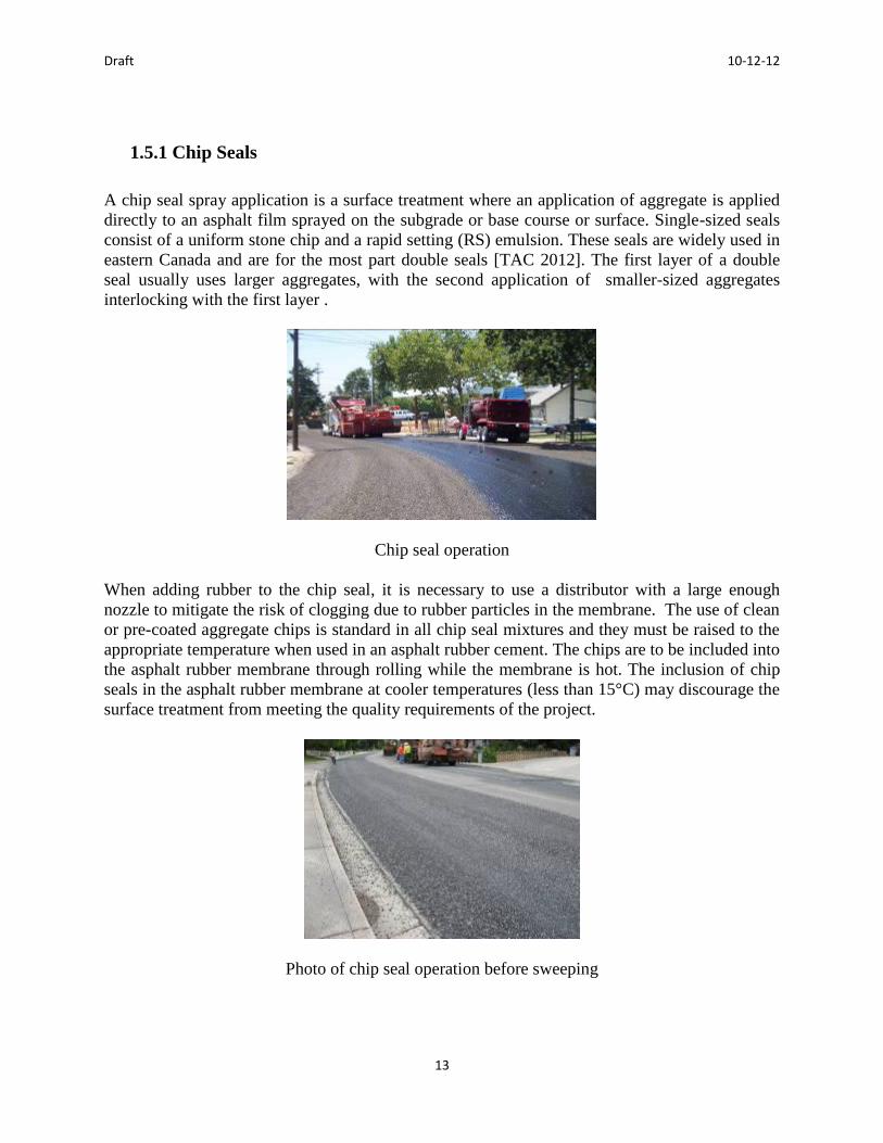
A chip seal spray application is a surface treatment where an application of aggregate is applied
directly to an asphalt film sprayed on the subgrade or base course or surface. Single-sized seals
consist of a uniform stone chip and a rapid setting (RS) emulsion. These seals are widely used in
eastern Canada and are for the most part double seals [TAC 2012]. The first layer of a double
seal usually uses larger aggregates, with the second application of smaller-sized aggregates
interlocking with the first layer .
Chip seal operation
When adding rubber to the chip seal, it is necessary to use a distributor with a large enough
nozzle to mitigate the risk of clogging due to rubber particles in the membrane. The use of clean
or pre-coated aggregate chips is standard in all chip seal mixtures and they must be raised to the
appropriate temperature when used in an asphalt rubber cement. The chips are to be included into
the asphalt rubber membrane through rolling while the membrane is hot. The inclusion of chip
seals in the asphalt rubber membrane at cooler temperatures (less than 15°C) may discourage the
surface treatment from meeting the quality requirements of the project.
Photo of chip seal operation before sweeping

Draft 10-12-12
14
1.5.2 Interlayers
Interlayers are required for the maintenance and rehabilitation of existing pavement
infrastructure. Both chip seals and interlayers use the same equipment and application
procedures. Structurally sound pavements are usually repaired using high viscosity rubberized
binders over severe cracks. The application of rubberized binders in interlayers and chip seals
provides a longer service life than conventional asphalt binders and longer performance in
resisting reflective cracking.
Photo of an interlayer
Schematic of an interlayer
1.5.3 Hot Mix Asphalt
HMA includes a wide range of aggregate mix types including gap-graded, open-graded, open-
graded high binder and dense-graded. The gap- and open- graded mixes can be successfully
placed using the wet process high viscosity rubber binder in surface courses while dense-graded
mixes tend to use the wet process terminal blends or no agitation binders. These are the
applications which have been used normally by agencies in the USA and Canada. However, the
rubber used in the United States for the field blended products tends to be coarser than that used
in Ontario.
Draft 10-12-12
15
1.6 Overview of Asphalt Rubber Binder Production
Both HMA and spray applications can use the wet process high viscosity asphalt rubber binders.
They are produced using the same method. However, the primary difference is related to the
interaction between the CRM and the asphalt cement to successfully produce enough asphalt
rubber cement to create RMA at the specified rate. For spray applications, asphalt cement is
usually produced near the job site and must be coordinated with application operations. For
HMA applications, the asphalt cement is produced at the plant site.
The quality of an asphalt rubber cement is dependent on the proportion of the ingredients, the
temperature at production, the degree of agitation and the time it takes to complete the
production. Temperature is an especially critical component of binder production and
temperature gauges and/or thermometers must be visible and monitored frequently. The tanks
that store the asphalt rubber binder between the initial blending and the application of the
material must be heated and insulated to maintain the appropriate temperature for application.
Transfer lines should also be insulated to maintain heat. The equipment used to produce and
store the asphalt-rubber should be equipped with a heater or heat exchangers to heat the asphalt
cement and/or asphalt-rubber cement. This is especially important in Canada due to the large
change in temperatures that can occur during the day and over the course of a number of weeks.
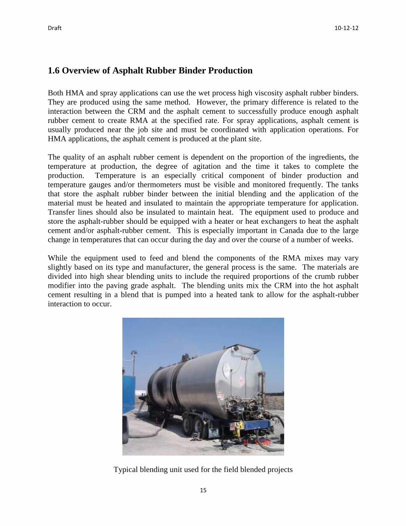
While the equipment used to feed and blend the components of the RMA mixes may vary
slightly based on its type and manufacturer, the general process is the same. The materials are
divided into high shear blending units to include the required proportions of the crumb rubber
modifier into the paving grade asphalt. The blending units mix the CRM into the hot asphalt
cement resulting in a blend that is pumped into a heated tank to allow for the asphalt-rubber
interaction to occur.
Typical blending unit used for the field blended projects

Draft 10-12-12
16
To thoroughly agitate the high viscosity asphalt rubber, augers are used to keep the CRM
particles from settling or floating to the surface. Agitation should be monitored periodically to
maintain sufficient dispersion of CRM particles. To monitor the viscosity of the asphalt rubber
interaction, a hand held rotational viscometer is used. The asphalt rubber binder must meet the
minimum viscosity specification and the interaction time should be at least 45 minutes before it
can be included in a hot mix or spray application [ASTM 2006a].
Photo of a Haake Viscometer measuring the viscosity of the binder
1.6.1 Holdover and Preheating Issues
There are four main areas of concern when working with asphalt rubber binders since the
temperature of the cement has a strong influence on the quality of the product. First, the heating
period for the asphalt rubber should be discontinued 4 hours after the 45 minute reaction period.
Second, the rubber asphalt cement can only be reheated twice before the quality is compromised.
Third, the asphalt rubber cement must meet all specified quality requirements. Finally, if the
viscosity of the rubber asphalt has to be restored, additional CRM can be added up to a
maximum of 10% of the binder mass. In short, if holdover is required, it is important that the
aforementioned procedures are implemented to ensure the quality is maintained.
1.6.2 Required Documentation
When using RMA pavement, quality control and assurance procedures must be followed to
ensure the material and application are in accordance with the local agency specifications. The
asphalt rubber cement production log should be submitted as required documentation during the
project. In addition, laboratory test results related to the specification including the chemical
composition of the scrap tire and natural rubber used as CRM and the asphalt modifier, if
included in the cement, should be documented. All documentation should be provided to the
contract administrator when the materials are delivered. Samples of the components and the
cement are typically tested by the owner to ensure specification compliance. These are in
accordance with the agency specification requirements.

Draft 10-12-12
17
The approved asphalt rubber cement design profile should be available at the blending site and
should contain the laboratory test results and the proportions of the components of the cement.
The binder design profile that accompanies the binder material from the supplier is a guide that
indicates the tested properties of the asphalt cement. The test data can provide potential warning
of specification non-compliance and provide the opportunity for corrective measures to be taken.
Typical binder profile for field blended cements
A log of the production of the asphalt rubber cement should also be produced for each project,
documenting the weight of each component, the reaction start time, the results of each viscosity
test, which includes the time and the asphalt temperature, and the time when the batch of asphalt
rubber cement was metered into the asphalt concrete plant. The log should also include any
holdover information and/or reheat cycle information on the batch including the time heating
was discontinued, the time reheating began, the corresponding asphalt rubber cement
temperature, crumb rubber addition weight and time of addition, if applicable, and the results of
any subsequent viscosity test results.
1.6.3 Sampling and Testing
Sampling and testing should be done for the asphalt cement periodically depending on the nature
of the materials, the project size and the available resources. In addition, testing the asphalt
rubber cement requirements and sampling should be conducted whenever there are changes to
any material or in the material behaviour. Sampling can also be conducted during production
and construction with limited interference to either process and with limited expense.
At least one set of viscosity tests is required to comply with the specifications for an asphalt
rubber batch and holdover load. The results of every viscosity test, including the time of the test
and the asphalt rubber cement temperature should be submitted to the contract administrator.

Draft 10-12-12
18
1.7 Terminal Blends
This wet process involves the CRM blending into the asphalt cement at the asphalt refinery. It
can be ordered directly from the supplier and does not require any equipment modifications. It
can also be tested according to the PGAC specifications as described earlier. This method does
not require any additional agitation as the CRM is distributed evenly in the mix. This is possible
due to the fact the CRM particles are finer in comparison to the wet high viscosity process. The
particles break down through the normal circulation within the asphalt storage tank as opposed to
requiring special mixing. These asphalt rubber cements may undergo significant modification
changes. In any case, the minimum viscosity should be monitored to ensure the specifications
are met [AI 2008].
The storage of terminal blended rubberized asphalts is similar to other blended asphalts. They are
storage-stable binders, as long as the tire rubber is fully digested into the binder. No special
equipment is required for shipment or paving with terminal blended asphalt. The material is
delivered to the hot mix plant by truck, mixed and shipped to the job and no special equipment is
required for paving or odour/fume control. The terminal blend mix is produced and compacted
like regular hot mix asphalt. In some cases, the contractor will need a dedicated storage tank for
the terminal blend asphalt cement.
1.7.1 Required Documentation
When using the wet process terminal blended RMA, quality control and assurance procedures
must be followed to ensure the material and application is in accordance with the agency
specifications. The terminal blend production log should be submitted as required
documentation during the project. In addition, laboratory test results related to the specification
including the chemical composition of the scrap tire rubber used as CRM should be documented.
All documentation should be provided to the contract administrator when the materials are
delivered. Samples of the components and the asphalt cement are typically tested by the owner
to ensure specification compliance.
A log of the production of the terminal blend rubber cement should also be produced for each
project, documenting the weight of each component, the reaction start time, the results of each
viscosity test, including the time and the asphalt temperature, and the time when the batch of
asphalt rubber cement was metered into the asphalt concrete plant.
1.8 Warm Mix Additives
Warm mix asphalt technologies were developed in Europe [FHWA 2008] in an effort to reduce
both greenhouse gas emissions and energy requirements (and hence costs) by reducing the
temperatures at which asphalt mixes are produced and placed. The direct benefit of WMA is
largely the reduction in production temperatures, from 150 to 165°C for conventional HMA
mixes to less than 120°C for WMA. This has the effect of reducing plant emissions and costs

Draft 10-12-12
19
associated with emission control. In addition, there is a direct savings in energy costs to heat the
asphalt mix [TAC 2012].
The three main WMA categories are: organic additives, chemical additives, and asphalt foaming
systems. Organic additives are typically paraffin based organic compounds. Chemical additives
are predominantly crystalline hydrated aluminum silicates, the most popular of which is
synthetic zeolite. The asphalt foaming systems involve first pre-coating the aggregate with a
softer binder, which allows for a lower mixing and compaction temperature, and then using a
harder binder that is foamed to improve workability. Although the technology is relatively new,
WMA asphalt mixes are considered to be acceptable for use provided they meet similar
requirements to those of HMA. For more information on the warm mix additives and
technologies used, please refer to the website of the Warm Mix Asphalt Technical Working
Group (WMA TWG) at www.warmmixasphalt.com.
Warm mix technologies can be used with asphalt rubber mixes allowing for the mixes to be
placed at night and in cooler climates. They also provide potential benefits through increased
workability of asphalt rubber mixes, extending the paving season and allowing their use where
asphalt rubber could not be used before. In addition, warm mix technologies can improve
working conditions, reducing undesired asphalt rubber odour and blue smoke associated with
conventional asphalt rubber placements and reducing fuel usage by reducing production
temperatures by 20 to 45oC [Hicks et. al 2011, Cheng et. al 2011].
1.9 Overview of RMA Construction
RMA should be carefully mixed, transported and placed. The appropriate sampling and testing
procedures should be done to ensure the correct degree of quality is met. Further details on the
RAC construction procedures are provided in subsequent chapters.
1.9.1 Preparation for Paving
The paving surface must be prepared prior to the production of the RMA or spray application.
Surface preparation includes removal and replacement of deteriorated pavement through cold
milling or grinding for smoothness and/or to restore or adjust profile, crack filling and/or sealing.
Patching is conducted using industry best practice and dense graded asphalt concrete. Cracks
should not be overfilled since any excessive sealer/filler will cause bumps in the overlay that will
be transferred to the RMA mat during compaction. Any pavement ruts should be filled as
necessary. If a leveling course is required, a fine dense-graded asphalt concrete mix should be
used. Immediately before the mixtures are delivered, the surface should be swept and the tack
coat applied.
Draft 10-12-12
20
1.9.2 Mixing
Hot mix delivery is the same as conventional HMA delivery with additional care to
temperatures. While any type of haul truck can be used to deliver conventional asphalt concrete
materials, bottom dumps and windrows are not recommended for use when the ambient and
pavement surface temperatures are cool. RMA should not cool below its minimum laydown
temperature during transport to the job site and tarps can be used to reduce the cooling of the
material.
1.9.3 Placement
The RMA temperatures in both the paver hopper and mat should be monitored throughout the
paving operation. To achieve a high quality pavement, the paver should minimize starting and
stopping and a high level of coordination of the mix delivery and placement should be met. A
consistent paver speed is required to maintain a uniform head of material and to control the
thickness of the pavement. The paver wings should be carefully dumped before the mix
collected in the corners cools, though the wings should never be dumped in an empty hopper.
Slat conveyors should not be allowed to run empty or close to empty.
1.9.4 Compaction
Adequate compaction is necessary to achieve the specified level of performance and durability of
an asphalt pavement. Gap-graded RMA mixes require more compaction than conventional
dense-graded asphalt concretes due to coarse aggregate structure and stiff asphalt rubber
cements. Compaction is dependent on temperature and requires compactive effort. For gap-
graded mixes, breakdown compaction is necessary and performed in vibratory mode, unlike
open-graded mixes that do not have compaction requirements since they are usually used as
surface courses with thin lifts. Open-graded mixes achieve compaction with only a few passes of
a roller operating in the static mode.
Breakdown compaction of gap-graded rubberized asphalt should be conducted before the
temperature of the mat is below 138°C. The mat temperature should be monitored during the
placement and compaction processes so that adjustments to the rate of compaction can be made.
An adequate number of breakdown rollers should also be used since breakdown rolling
performed outside of the specified temperature range will result in poor quality pavement.
Vibratory rolling should not be conducted below the minimum breakdown rolling temperature or
after static rolling. Pneumatic rollers are not recommended because they stick to the rubberized
asphalt mat.
Draft 10-12-12
21
1.9.5 Testing
To determine the degree of compaction needed to develop adequate in-place density of gap-
graded RMA materials, test strips should be created. During test strip compaction, nuclear
gauges should be testing the mat and the data should be later correlated with the core results in
order for the nuclear density to provide accurate data for quality control.
1.10 Benefits and Other Considerations
The application of RMA has many reported benefits [Caltrans MTAG (2006), Caltrans AR guide
(2003)]. The durability of the surface layer of the material should result in a longer service life.
This durability is mainly due to its improved resistance to fatigue, reflection cracking, and aging
resulting in a lower life cycle cost of the material. Inclusion of the rubberized asphalt may
decrease the thickness of the RMA layer and reduce noise due to the inclusion of rubber in the
material. There are also other environmental benefits to using RMA as rubber waste is being
diverted from landfills to once again become a viable product.
1.10.1 Cost Considerations
When considering the cost of RMA over the pavement life, a standard life cycle cost analysis
should be carried out. Most Canadian transportation agencies incorporate some form of
economic analysis into their pavement design, preservation and rehabilitation design process
based on a recent Canadian transportation agency survey [TAC 2012]. Life cycle cost analysis
(LCCA) only refers to the financial cost associated with a project. LCCA evaluates competing
alternatives by including not just initial construction costs, but also the expected cost to maintain
the asset in a functional condition for its service life. This process is widely applied because it
can evaluate differences between design options, such as pavement type and various feasible
design cross sections [TAC 2012]. Local practices should be applied when conducting the
LCCA on a specific RMA project. At this time, the performance information for RMA projects
is not sufficient to perform cost analysis.
1.10.2 Environmental Benefits
The inclusion of rubber waste material reduces the number of rubber products in landfills and
tire stockpiles. Consequently, the effective and engineered usage of RMA can provide many
environmental benefits as the rubber waste material can be recycled into the HMA in either the
wet or dry process as described earlier. RMA has also been shown to reduce tire/pavement noise
levels which provide an ideal application to areas where excess noise pollution is a hazard, such
as in residential neighbourhoods and near hospitals. The inclusion of rubber materials in HMA
also has been shown to pose limited or no increased health or air quality risks [Sacramento 1999,
Hicks 2011].

Draft 10-12-12
22
1.11 Summary
RMA can provide technical, economic and environmental benefits in Canada. When properly
engineered, it can provide a long lasting pavement while also mitigating the number of tires that
end up in landfills. RMA production and construction procedures have been successfully applied
both nationally and internationally and this manual is directed at highlighting best practices.

Draft 10-12-12
23
2.0 Application and Usage Guide for Asphalt Rubber Cement
2.1 Introduction
The materials and their proportions that are included in the asphalt rubber cement are determined
in accordance with the specifications of the specific project. The pavement structural design will
dictate the total thickness required and the type of HMA or RMA that is used will be dictated by
the traffic loading and environment. The materials including the asphalt cement PGAC and
associated aggregate properties for the RMA will all meet the conventional HMA requirements.
Some of the descriptions of materials in this chapter are repeated for ease of understanding.
2.2 Crumb Rubber Modifier (CRM)
CRM is composed of ground scrap tires, tread buffings, and other wastes or excess rubber
products. There exist a number of processes and equipment used to produce the required range
of CRM material to be used in asphalt paving materials. These products are produced in Ontario
and can be obtained from the vendors shown in Chapter 1 of this manual.
2.3 Asphalt Cement
Design of paving mixtures and selection of the optimum proportions of their constituents require
engineering and experience. For example, for low volume roads, a relatively higher percentage
of asphalt cement is appropriate to ensure that pavement durability is provided. On a high
volume road, with heavy truck traffic, permanent deformation distress would likely become a
problem if relatively high asphalt cement contents were used. Thus, some compromise is
necessary. Design criteria and the selection of appropriate asphalt cement are normally specified
in consideration of traffic, climate and requirements necessary to mitigate the distress.
In Canada, asphalt cement and HMA design requires consideration of a number of distress types
to which the pavement may be subjected in-service, including: low temperature cracking,
permanent deformation (rutting, shoving, etc.), fatigue cracking, moisture sensitivity and
stripping, aging of the asphalt/aggregate system and durability. Again, the usage of PGAC
assists in ensuring long term performance in the field.
When using asphalt rubber cements, it is important that the binder be tested to ensure it meets all
of the Superpave test procedures [TAC 2012]. The physical asphalt cement properties are
measured on original (unaged) binder, on short term aged sample with the Rolling Thin Film
Oven (AASHTO T240-10) and on long term aged samples in the Pressurized Aging Vessel
(AASHTO R28-10). The Rolling Thin Film Oven simulates plant aging of binders during
asphalt mix production, while the Pressurized Aging Vessel simulates in-situ aging of in-service
Draft 10-12-12
24
asphalt mixes [TAC 2012]. In addition, the following tests listed below are also performed on
the PGAC.
Flash point tests (AASHTO T79-10) are used to determine the temperature at which
asphalt binder fumes first may flash or spark.
Rotational viscosity (AASHTO T316-10) measures the viscosity at high temperatures
and is a measure that ensures the asphalt is fluid enough for pumping at the asphalt
mix plant, as well as to provide design temperatures for mixing and compaction of
asphalt mixes.
Dynamic shear (AASHTO T315-10) is used to measure the flow properties of liquid
asphalt binders at intermediate to high temperatures. The test is performed on original
binder specimens and after conditioning in a Rolling Thin Film Oven and Pressurized
Aging Vessel to ensure compliance with requirements that have been established to
mitigate pavement rutting distress.
Creep stiffness test (AASHTO T313-10) is performed on Pressurized Aging Vessel
residue, and measures the flexural creep stiffness of binder specimens using a
bending beam rheometer. The test is used to provide an indication of the low
temperature stiffness and cracking potential of an asphalt binder.
Direct tension test (AASHTO T314-10) is used to measure the failure properties
(stress and strain) of an asphalt binder at low temperatures.
Improved Asphalt Cement and Rubberized Asphalt Cement Grading
Over the past 15 years, asphalt binders have been specified and accepted in Ontario paving
contracts based on their Superpave™ grades. Superpave was a product of the U.S. Strategic
Highway Research Program (SHRP) that concluded in the early 1990s. It was completed in
record time and hence contains certain assumptions and compromises that have produced a
number of shortcomings. Research to address some of the main issues in Ontario has been
completed and this has resulted in the recent publication, validation and implementation by the
Ministry of Transportation of three standard laboratory test methods: LS-228, LS-299, and LS-
308.
The LS-228 Accelerated Aging of Asphalt Cement Using Modified Pressure Aging Vessel
Protocols standard assesses durability of a binder in terms of its resistance to oxidative aging in
the Rolling Thin Film Oven (RTFO) followed by the Pressure Aging Vessel (PAV). Binders are
aged according to standard Superpave protocols for 20 hours with 50 grams of asphalt binder in
each PAV pan (film thickness of 3.2 mm). The low temperature grades are compared with those
obtained after 20 hours of aging with 12.5 grams in each pan (film thickness of 0.8 mm), after 40
hours of aging with 50 grams in each pan, and in the presence of moisture. It has been shown
that such simple changes allow for a more accurate determination of low temperature grades.
While the regular 20 hours of aging in the PAV provides a single point measurement, doubling
the time to 40 hours, reducing the film thickness, and/or adding moisture, can reveal if the

Draft 10-12-12
25
grading properties are expected to persist in long-term service. Superior binders are found to
deteriorate by less than half a grade (< 3°C) while inferior ones have been found to lose as much
as one or two full grades (6-12°C). Figure 1 shows an image of a commercially available Prentex
PAV. Figure 2 shows grade losses for a poor performing field-blended, rubberized asphalt
cement sample from an Ontario paving trial (Xu et al., 2013).
Prentex Model 9300 Pressure Aging Vessel for Accelerated Laboratory Aging.
Deterioration of Low Temperature BBR Grades for Field Blended Rubberized Asphalt
Cement Sample due to Modified PAV Aging According to LS-228 (Xu et al., 2013). Note: A 10°C grade deficit at low temperatures usually has major negative implications for thermal
cracking performance reducing the confidence that a road is not damaged in any given winter from the
intended 98% to around 10%.
The LS-299 Determining Asphalt Cement’s Resistance to Ductile Failure Using Double-Edge-
Notched Tension Test (DENT) standard determines the strain tolerance of a binder in the ductile
state. While Superpave only specifies low strain rheological properties, LS-299 sets a lower limit
on the high strain tolerance in the ductile state, as determined by an approximate Critical Crack
Tip Opening Displacement (CTOD). The CTOD indicates by how much a very thin fiber (fibril)
of asphalt binder can stretch before it fails. This property has provided an improved correlation
with fatigue cracking in mixtures and trial sections. The specification limits that were set for the
CTOD are based on those obtained for good quality western Canadian asphalt cements, with the
intention to prevent a deterioration of the ductile strain tolerance due to modification. Figure 3
provides images of the specimens with three different ligament lengths prior to testing and the
fibrils between two aggregate particles that are modeled by the CTOD measurement. Figure 4
provides typical DENT test results for unmodified asphalt cement, a field-blended rubberized
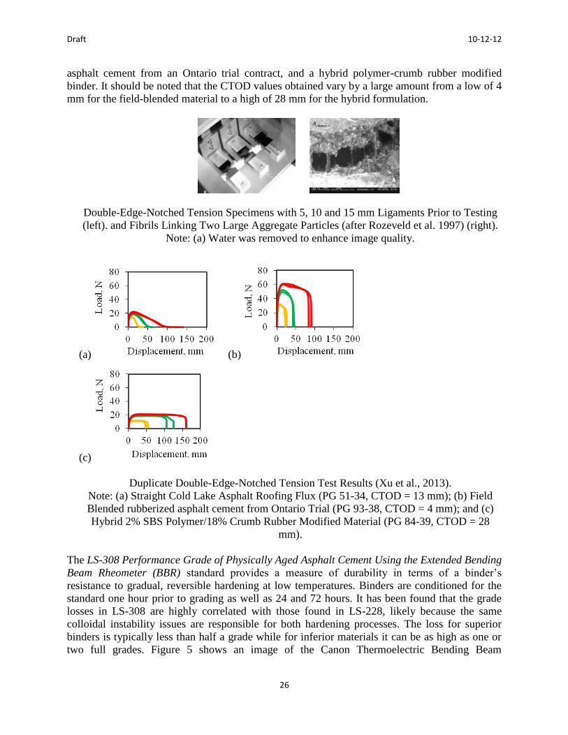
Draft 10-12-12
26
asphalt cement from an Ontario trial contract, and a hybrid polymer-crumb rubber modified
binder. It should be noted that the CTOD values obtained vary by a large amount from a low of 4
mm for the field-blended material to a high of 28 mm for the hybrid formulation.
Double-Edge-Notched Tension Specimens with 5, 10 and 15 mm Ligaments Prior to Testing
(left). and Fibrils Linking Two Large Aggregate Particles (after Rozeveld et al. 1997) (right).
Note: (a) Water was removed to enhance image quality.
(a) (b)
(c)
Duplicate Double-Edge-Notched Tension Test Results (Xu et al., 2013).
Note: (a) Straight Cold Lake Asphalt Roofing Flux (PG 51-34, CTOD = 13 mm); (b) Field
Blended rubberized asphalt cement from Ontario Trial (PG 93-38, CTOD = 4 mm); and (c)
Hybrid 2% SBS Polymer/18% Crumb Rubber Modified Material (PG 84-39, CTOD = 28
mm).
The LS-308 Performance Grade of Physically Aged Asphalt Cement Using the Extended Bending
Beam Rheometer (BBR) standard provides a measure of durability in terms of a binder’s
resistance to gradual, reversible hardening at low temperatures. Binders are conditioned for the
standard one hour prior to grading as well as 24 and 72 hours. It has been found that the grade
losses in LS-308 are highly correlated with those found in LS-228, likely because the same
colloidal instability issues are responsible for both hardening processes. The loss for superior
binders is typically less than half a grade while for inferior materials it can be as high as one or
two full grades. Figure 5 shows an image of the Canon Thermoelectric Bending Beam

Draft 10-12-12
27
Rheometer that is used for LS-308 grading. Figure 6 shows the losses in low temperature grade
as a function of cold conditioning time for a superior binder made with Cold Lake asphalt
cement (in green) and an inferior material from an Ontario pavement trial (in red).
Canon Thermoelectric Bending Beam Rheometer.
Low Temperature Grade Losses for Two Rubberized Asphalt Cements (Xu et al., 2013).
Note: The poor performer (in red) loses 10°C over 72 h of conditioning at -18°C while the
superior performer (in green) loses only a modest 3.6°C after conditioning at -24°C.
Employing these modified testing protocols can produce lower temperature limits that are
warmer by one or two full grades (6-12°C), reducing the confidence that a pavement is not
exposed to damage in any given winter from the intended 98% to less than 50% or even 10%.
Hence, it allows user agencies to better pay for performance by preventing the use of substandard
materials in a given climatic zone. The above three test methods have been extensively validated
with Ontario pavement test sections and regular contracts and have consistently been able to
explain from best-case to worst-case cracking performance differences in adjacent sections and
regular contracts. Preliminary testing on rubberized asphalt cement (RAC) has shown that certain
types of compositions are particularly sensitive to the effects of conditioning at low temperatures
(Xu et al., TRB 2013). Hence, caution is warranted to assure that the RAC not only meets regular
Superpave criteria but also the improved Ontario specifications as recently developed.

Draft 10-12-12
28
When using asphalt rubber binders, it is important that all the conventional test requirements be
met for the given design.
2.4 Additives
Additives are materials that are included in the asphalt cement mixture to encourage interaction
and the production of higher quality products. Possible additives used with CRM include:
extender oils, high natural rubber (HNR), polymers (mainly in no agitation binders), and mineral
admixtures which improve workability and compatibility of the mix. Some extender oils can
improve RMA performance, others may have detrimental effects.
2.5 Rubberized Asphalt Applications
2.5.1 Hot Mix Asphalt (HMA) Applications
HMA includes a wide range of aggregate mix types, including gap-graded, open-graded, open-
graded-high binder mixes, and dense-graded mixes. The gap- and open-graded mixes have been
successfully placed using the wet process high viscosity rubber binder in surface courses while
dense-graded mixes tend to use the wet process terminal blends or no agitation binders. These
are the products currently used in Ontario.
2.5.2 Rubberized Spray Applications (Seal Coats/Surface Treatment and
Interlayers)
Asphalt rubber cement or terminal blends can be effectively incorporated into various typical
Canadian seal coats, surface treatments and interlayers. Selection of the appropriate binder will
depend largely on the application and local specifications should be followed in the design and
construction of these pavements [TAC 2012]. These products have not yet been used in Ontario,
but are being considered.
2.6 Asphalt Rubber Hot Mixes
2.6.1 Dense-Graded Asphalt Mixes
The dense-graded mix is a well-graded HMA mixture intended for usage in various layers of the
pavement structure. It is designed to be impermeable and generally specified in accordance with
the nominal maximum aggregate size [WSDOT 2012]. The aggregate gradation closely follows

Draft 10-12-12
29
the FHWA’s 0.45 power curve for maximum density. The most common HMA mix designs in
Canada are dense-graded. Typical gradations are near the 0.45 power curve, but not right on it.
Generally, a true maximum density gradation (exactly on the 0.45 power curve) would result in
unacceptably low VMA. These mixes are further categorized as fine graded or coarse graded
depending on the size and distribution of the aggregate contained in the mix. The fine graded
mixes contain a higher percentage of fine aggregate while the coarse-graded mixes contain larger
aggregate [WSDOT 2012]. Examples of dense-graded mixes would include SP 25, SP 29, SP
12.5 and SP 9.5 [Ontario MTO, 2011].
Dense graded rock
Dense-graded RMA can be effectively designed using the wet process terminal blend rubberized
asphalt. However, usage of the dense-graded mixes with asphalt rubber is limited as the
additional cost of the rubber has not always translated to improved field performance when a
LCCA is conducted. This is related to the dense grade of aggregate whereby there are not
enough voids available in the mix to allow the asphalt rubber cement to greatly impact the
volumetric properties. However, if dense-graded RMA is suitable for the design, it is best used
with the wet process terminal blend.
2.6.2 Gap-Graded Mixes
A gap-graded mix refers to a HMA where the aggregate gradation contains only a small
percentage of aggregate particles in the mid-size range. This results in a gradation curve that is
flat in the mid-size range [WSDOT 2012]. A good example of a Canadian gap- graded mix is a
Stone Mastic Asphalt (SMA). SMA is a gap- graded asphalt mix that typically contains 100%
crushed stone materials. The asphalt cement is often modified and in this case an asphalt rubber
cement can be used in combination with some type of filler [TAC 2012]. The coarse stone
skeleton is designed with a relatively thick asphalt/filler mastic to provide excellent durability
while also providing increased resistance to permanent deformation through the stone-to-stone
contact and increased fatigue resistance due to the thick mastic coating on the aggregate
[Kennepohl, 1992]. A limitation to SMA is that the high SMA bituminous contents can lead to
friction issues [TAC 2012].

Draft 10-12-12
30
HMA gap-graded mixes can be prone to segregation during placement. Gap-graded mixes
provide adequate void space for the asphalt rubber binder to positively affect the material
properties. It has been shown that many technical benefits can be achieved when used in
conjunction with the wet process high viscosity asphalt rubber cements.
Gap graded rock
2.6.3 Open-Graded Course (OGC) Mixes
The open-graded course mix gradations contain only a small percentage of aggregate particles in
a small range. This results in more air voids because there are not enough small particles to fill
in the voids between the larger particles. The curve is near vertical in the mid-size range and flat
and near-zero in the small-size range [WSDOT 2012]. Open graded courses have more void
spaces than gap-graded mixes to allow for drainage through the pavement. Thus, they are
permeable and allow for quick removal of surface water which reduces the potential of
hydroplaning and water spray. In addition, the open texture acts to lower pavement/tire noise.
OGC mixes are surface course mixes and are placed in conjunction with noise walls along
freeways in heavily populated urban areas [TAC 2012].
OGC mixes can successfully be designed using an asphalt rubber cement to reduce splash and
spray while also providing good surface friction. High binder OGC can also be designed with
the same properties as OGC mixes; although, drainage can be limited while the durability of the
pavement is improved.
Open graded rock

Draft 10-12-12
31
2.6.4 Warm Mix Asphalt Technology
Warm mix asphalt technologies allow asphalt producers to lower the mixing and placement
temperatures of the asphalt pavement. The lower temperatures result in fuel consumption
savings and decreased production of greenhouse gases. In addition, engineering benefits include
better compaction on the road, the ability to haul paving mix for longer distances, and extension
of the paving season by being able to pave at lower temperatures. Although the technology is
relatively new, WMA mixes are considered to be acceptable for use provided they meet similar
requirements to those of HMA [NAPA 2012].
Warm mix technologies have been used with asphalt rubber and terminal blend mixes allowing
for the mixes to be placed at night and in cooler climates. They also provide potential benefits
through increased workability of asphalt rubber mixes, extension of the paving season and
allowing their use where these products could not be used before [Hicks 2011, Cheng et al.
2011].
2.7 Asphalt Rubber Spray Applications
There are a number of different asphalt rubber spray applications that are applied to pavements
depending on the requirements of the project. A number of different spray application types are
discussed in further detail below.
2.7.1 Chip Seal Construction Process
Chip seal spray application is a surface treatment that is greatly affected by construction
operations and site conditions. Extreme care must be used when applying chip seals to maintain
the appropriate level of quality needed for a project, especially in regards to the temperature of
the project site, the aggregate type and pavement infrastructure.
The inclusion of asphalt rubber in chip seal material creates a thicker membrane. This
practically means that the aggregate in the mix must be large enough to withstand the thick
membrane while maintaining a uniform mix. The nozzle size for spraying should be sufficient to
prevent clogging.
Construction of chip seals is a rapid process, usually performed at a production rate of 8 to 10
km per day. As mentioned above, temperature can drastically affect the quality of the final
product, regardless of the type of binder. The use of clean or pre-coated aggregate chips is
standard in all chip seal mixtures and they must be raised to the appropriate temperature when
used in an asphalt rubber cement. The chips are to be included into the asphalt rubber membrane
through rolling while the membrane is hot. The inclusion of chip seals in the asphalt rubber
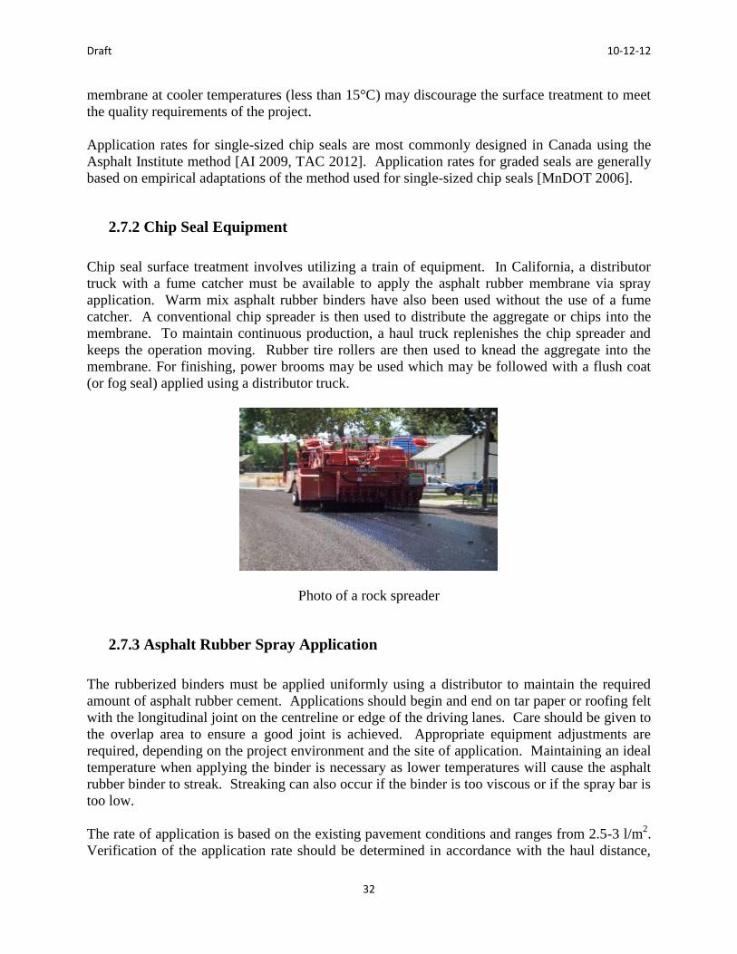
Draft 10-12-12
32
membrane at cooler temperatures (less than 15°C) may discourage the surface treatment to meet
the quality requirements of the project.
Application rates for single-sized chip seals are most commonly designed in Canada using the
Asphalt Institute method [AI 2009, TAC 2012]. Application rates for graded seals are generally
based on empirical adaptations of the method used for single-sized chip seals [MnDOT 2006].
2.7.2 Chip Seal Equipment
Chip seal surface treatment involves utilizing a train of equipment. In California, a distributor
truck with a fume catcher must be available to apply the asphalt rubber membrane via spray
application. Warm mix asphalt rubber binders have also been used without the use of a fume
catcher. A conventional chip spreader is then used to distribute the aggregate or chips into the
membrane. To maintain continuous production, a haul truck replenishes the chip spreader and
keeps the operation moving. Rubber tire rollers are then used to knead the aggregate into the
membrane. For finishing, power brooms may be used which may be followed with a flush coat
(or fog seal) applied using a distributor truck.
Photo of a rock spreader
2.7.3 Asphalt Rubber Spray Application
The rubberized binders must be applied uniformly using a distributor to maintain the required
amount of asphalt rubber cement. Applications should begin and end on tar paper or roofing felt
with the longitudinal joint on the centreline or edge of the driving lanes. Care should be given to
the overlap area to ensure a good joint is achieved. Appropriate equipment adjustments are
required, depending on the project environment and the site of application. Maintaining an ideal
temperature when applying the binder is necessary as lower temperatures will cause the asphalt
rubber binder to streak. Streaking can also occur if the binder is too viscous or if the spray bar is
too low.
The rate of application is based on the existing pavement conditions and ranges from 2.5-3 l/m2.
Verification of the application rate should be determined in accordance with the haul distance,

Draft 10-12-12
33
width and amount of asphalt rubber cement that is used during application. Dry, oxidized,
raveled or brittle application surfaces will require higher binder applications.
Warm mix technologies can be easily added into the asphalt rubber cement. Although there is
limited experience with these, no special considerations should be required when using a warm
mix technology with an asphalt rubber or a terminal blend binder [Hicks 2011, Cheng et al.
2011].
2.7.4 Aggregate Application
The application of the aggregate is facilitated through the use of a chip spreader that follows the
asphalt rubber distributor at a steady rate. The distributor is typically following 20-30 m behind
the chip spreader. The binder must have a sufficient viscosity to allow the aggregate to become
bonded. Due to the sensitive nature of aggregate application, the speeds and loads of the
equipment must be carefully monitored to ensure the seal is properly set. A uniform distribution
of the aggregate is necessary to limit areas of excess aggregate. In the case of excess aggregate,
the particles must be redistributed to another roadway or removed from new pavement before it
interferes with the embedment and adhesion properties. This is very important for preventing
any future failures. In areas where aggregate cover is inadequate, additional aggregate should be
immediately added before it sets. If the additional aggregate is added once the membrane sets,
adhesion will not be achieved and an overall poor quality chip seal will be the end result. The
degree of chip application must be monitored as an excess amount can have negative effects on
the embedment and adhesion of the paving structure. If, after sweeping, there are a number of
loose stones on the roadway edge, this may be an indicator of excess chip application, minimal
asphalt rubber application or the lack of proper embedment and adhesion.
Rate of aggregate application is usually determined through laboratory testing procedures prior
to construction. Alternatively, the aggregate could be laid out one-stone deep and weighed to
determine the necessary weight per unit area. The rate should be in the range of about 15-24
kg/m2. Embedment of the cover aggregate and individual chips should be checked to verify the
adequateness of the rate of application.
2.7.5 Rolling Asphalt Rubber Chip Seals
Rolling asphalt rubber chip seals requires pneumatic-tired rollers due to the kneading action
provided by the tires that encourages chip embedment to occur. The tires make contact with the
aggregate instead of the membrane without removing portions of the applied surface. Skirts
around the tires keep the heat in the process and help provide proper compaction. The
aggregates are oriented and further embedded as the rollers operate over the surface at reduced
speeds so as to not displace the aggregate.

Draft 10-12-12
34
2.7.6 Sweeping
Sweeping is conducted to remove any excess chips from the newly laid chip seal, minimizing
flying rocks. It is best to sweep the newly placed surface within 30 minutes of applying the chip
seal. Furthermore, during a cooler time of day, sweeping with a power broom is also desirable
for achieving a good quality pavement.
Sweeping the chip seal
2.7.7 Flush Coat or Fog Seal
A flush coat involves the application of a fog seal over a newly constructed asphalt rubber chip
seal, which is then followed by a sand cover. Fog seals aid in maintaining the quality of the chip
seals by helping to retain the cover aggregate and providing a uniform appearance. A fog seal is
applied at a rate of 0.2-0.45 l/m2
Application of the flush coat
2.7.8. Sand Cover

Draft 10-12-12
35
Sand cover is often used to prevent vehicle tires from picking up and tracking the chip seal
material. The sand cover layer is applied on top of the fog seal and spread at a steady rate of 1-2
kg/m2.
2.7.9 Traffic Control
To maintain the quality of a newly constructed chip seal, the traffic speed must initially be kept
below 40 km/h using flag persons, signage and/or a pilot car. The pilot car technique is most
preferred, as it is better able to control the speed of the traffic that will provide pneumatic tire
rolling and kneading of the pavement. Hot applied chip seals allow traffic to get back on the
pavement sooner than for conventional emulsion chip seals.
Traffic control for a chip seal
2.8 Summary
As noted above, the material and construction procedures for asphalt rubber cement and its usage
in HMA and chip seals/surface treatments are similar to those for conventional materials. The
same engineering principles and material selection philosophies are followed when using rubber
in asphalt pavement. The main difference with the asphalt rubber cement and RMA mix is that it
contains CRM either in the asphalt cement or aggregate portion. There are a number of different
RMA mixes that can be made depending on the gradation of the aggregate. The RMA mixes are
designed and tested in the same way that the various conventional HMA are tested, including PG
asphalt cement and other mix design tests.
Draft 10-12-12
36
3.0 Design and Specification Guide
3.1 Design Guides
References and resource guidelines on the application and maintenance of rubberized asphalt
concrete have been published by the Rubber Pavements Association, Arizona DOT, and the State
of California, where rubberized asphalt concrete (RAC) paving is widely used [Caltrans, 2008].
This chapter presents possible guides for use in Ontario
3.1.1 Publication Guide Resources
Most agencies in Canada have limited available information on the design and application of
RMA. This document is intended to fill that need, even though most information in existing
provincial design guides or the Transportation Association of Canada Pavement Asset Design
and Management Guide [TAC 2012] is applicable to the design and specification of RMA
pavement.
3.1.2 Where and Why Use Rubber Modified Asphalt?
RMA has the potential to provide many technical, economic and environmental benefits when
designed appropriately for a given situation. It can be used as a replacement for conventional
HMA. The higher binder content can improve durability [Hicks 2011] and RMA usage has
been shown to resist fatigue cracking, bleeding, flushing, deformation and reflection cracking
which are particular issues as the pavement gets older. Also, aggregate retention is improved
providing a more uniform and potentially stronger material [AI 2008, Sacramento 1999].
3.1.3 Tests for Asphalt Rubber
There are a number of tests that can be conducted on field blended asphalt rubber binder to
determine the properties of the material. A number of these tests are based on the ASTM and
AASHTO testing methods and should be used for further reference. Special tests used for asphalt
rubber binders have included the following:
Cone Penetration Test [AASHTO 2010 (Test T 49), ASTM 2006b]. A cone is used
to create an impression in a binder sample and a penetrometer measures the
impression to an accuracy of tenths of a millimetre. This test determines the
consistency of the asphalt rubber cement with larger particles of crumb rubber and
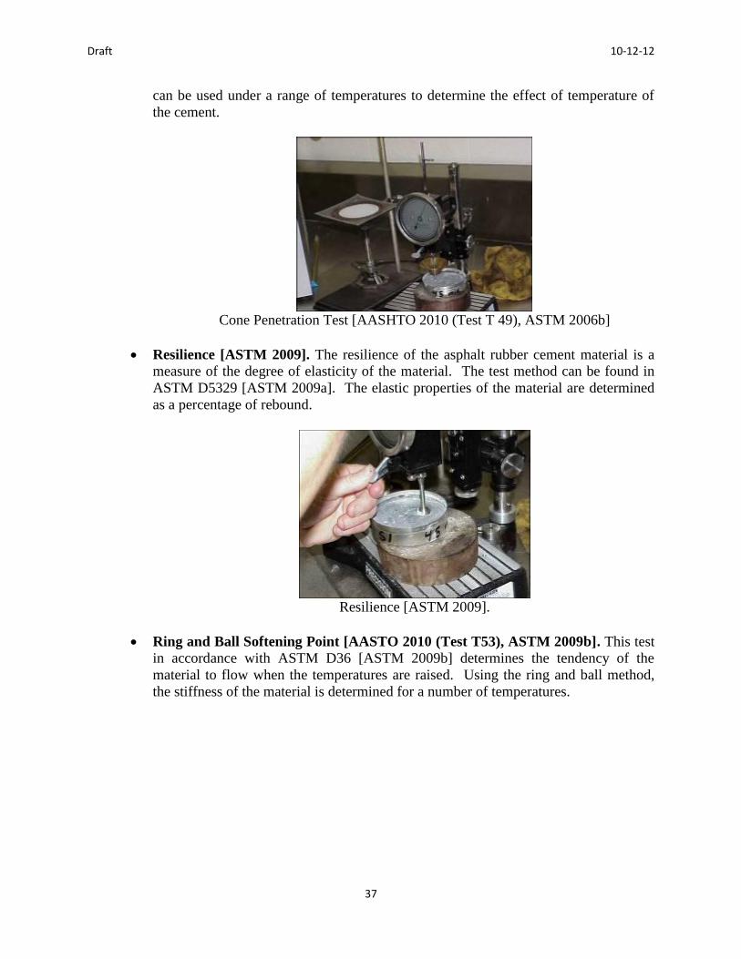
Draft 10-12-12
37
can be used under a range of temperatures to determine the effect of temperature of
the cement.
Cone Penetration Test [AASHTO 2010 (Test T 49), ASTM 2006b]
Resilience [ASTM 2009]. The resilience of the asphalt rubber cement material is a
measure of the degree of elasticity of the material. The test method can be found in
ASTM D5329 [ASTM 2009a]. The elastic properties of the material are determined
as a percentage of rebound.
Resilience [ASTM 2009].
Ring and Ball Softening Point [AASTO 2010 (Test T53), ASTM 2009b]. This test
in accordance with ASTM D36 [ASTM 2009b] determines the tendency of the
material to flow when the temperatures are raised. Using the ring and ball method,
the stiffness of the material is determined for a number of temperatures.
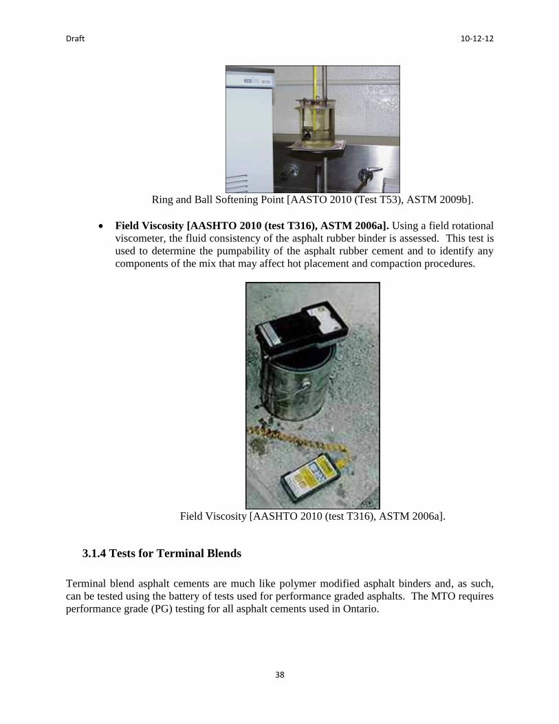
Draft 10-12-12
38
Ring and Ball Softening Point [AASTO 2010 (Test T53), ASTM 2009b].
Field Viscosity [AASHTO 2010 (test T316), ASTM 2006a]. Using a field rotational
viscometer, the fluid consistency of the asphalt rubber binder is assessed. This test is
used to determine the pumpability of the asphalt rubber cement and to identify any
components of the mix that may affect hot placement and compaction procedures.
Field Viscosity [AASHTO 2010 (test T316), ASTM 2006a].
3.1.4 Tests for Terminal Blends
Terminal blend asphalt cements are much like polymer modified asphalt binders and, as such,
can be tested using the battery of tests used for performance graded asphalts. The MTO requires
performance grade (PG) testing for all asphalt cements used in Ontario.
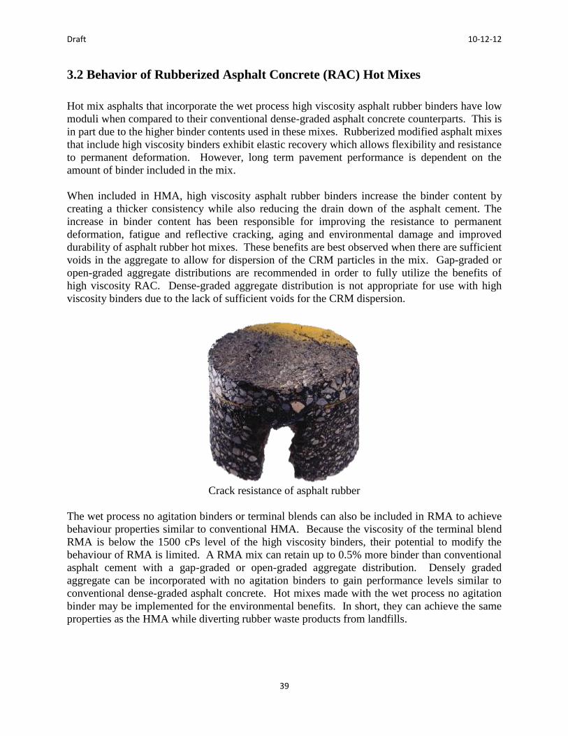
Draft 10-12-12
39
3.2 Behavior of Rubberized Asphalt Concrete (RAC) Hot Mixes
Hot mix asphalts that incorporate the wet process high viscosity asphalt rubber binders have low
moduli when compared to their conventional dense-graded asphalt concrete counterparts. This is
in part due to the higher binder contents used in these mixes. Rubberized modified asphalt mixes
that include high viscosity binders exhibit elastic recovery which allows flexibility and resistance
to permanent deformation. However, long term pavement performance is dependent on the
amount of binder included in the mix.
When included in HMA, high viscosity asphalt rubber binders increase the binder content by
creating a thicker consistency while also reducing the drain down of the asphalt cement. The
increase in binder content has been responsible for improving the resistance to permanent
deformation, fatigue and reflective cracking, aging and environmental damage and improved
durability of asphalt rubber hot mixes. These benefits are best observed when there are sufficient
voids in the aggregate to allow for dispersion of the CRM particles in the mix. Gap-graded or
open-graded aggregate distributions are recommended in order to fully utilize the benefits of
high viscosity RAC. Dense-graded aggregate distribution is not appropriate for use with high
viscosity binders due to the lack of sufficient voids for the CRM dispersion.
Crack resistance of asphalt rubber
The wet process no agitation binders or terminal blends can also be included in RMA to achieve
behaviour properties similar to conventional HMA. Because the viscosity of the terminal blend
RMA is below the 1500 cPs level of the high viscosity binders, their potential to modify the
behaviour of RMA is limited. A RMA mix can retain up to 0.5% more binder than conventional
asphalt cement with a gap-graded or open-graded aggregate distribution. Densely graded
aggregate can be incorporated with no agitation binders to gain performance levels similar to
conventional dense-graded asphalt concrete. Hot mixes made with the wet process no agitation
binder may be implemented for the environmental benefits. In short, they can achieve the same
properties as the HMA while diverting rubber waste products from landfills.

Draft 10-12-12
40
3.2.1 Mix Properties
An asphalt rubber cement should be designed based on the design requirements of the pavement
and the corresponding specifications. Consideration for the sources and grade of asphalt, asphalt
modifier and crumb rubber modifier (CRM) materials should be included in the development of
the design. Tests of the cement should also be conducted to determine whether the properties of
the design meet the specifications. This is usually achieved by testing samples of the asphalt
rubber cement at set intervals over a 24-hour interaction period.
Using the test data, a binder blend profile is created to evaluate the compatibility of the different
materials in the design, to determine the stability of the blend after it has been created and what
types of applications it is best suited for. Every project should document the binder blend profile
to maintain quality control and assurance.
Binder profile
3.2.2 Factors Affecting Performance
Pavement performance is dependent on several factors. It is necessary to ensure that the
pavement is properly designed to meet the required traffic and environmental loadings. This is
discussed in more detail in the next section. It is also necessary that the mix design in terms of
the materials, i.e. PGAC, aggregate type and gradations and the CRM meet all the design
requirements. The plant should be able to incorporate the CRM so that the overall mix meets the
standard HMA specifications. Finally, the mix should be hauled to the site and the mat should
be placed in accordance with the temperature specifications and all as-built performance
requirements should be met. Overall, the RMA should meet all the standard requirements for
conventional HMA and no extraordinary operations or procedures should be required.
3.3 Structural Design

Draft 10-12-12
41
The structural design of a rubberized asphalt concrete (RMA) mix is dependent on the traffic
loading, climate and functional classification of the road. For maintenance or preservation
projects, a thin overlay should be sufficient to restore ride and surface friction, reduce noise, and
improve the aesthetics of the pavement structure. The overlay design could either include gap-
graded or open-graded aggregate and would be designed in accordance with
provincial/municipal specifications. Gap-graded overlays should be compacted to a thickness
ranging from 30 to 60mm for optimal use as a structural component of the pavement. Open-
graded overlays are best utilized as a thin overlay for maintenance or preservation, but not for
improving the structural integrity of the pavement.
For rehabilitation projects, gap-graded asphalt rubber hot mixes are ideal to provide resistance to
reflective cracking. A gap-graded asphalt rubber hot mix is an alternative to the more commonly
used dense-graded asphalt concrete and can require half the overlay thickness of the
conventional mix (Caltrans MTAG). However, most states do not reduce the thickness; they just
expect better performance. For rehabilitation projects where cracking is severe, alternate RMA
mixes, including a rubberized stress absorbing membrane interlayer (SAMI) or an asphalt rubber
aggregate membrane interlayer, can be applied beneath the overlay as a crack interruption layer.
A layer of dense-graded asphalt concrete should be included directly beneath the gap-graded
RMA overlay if more than 60mm of pavement is required to meet the thickness requirement.
For new construction projects, instead of using a conventional dense-graded asphalt concrete, a
gap-graded asphalt concrete surface course could be substituted at an equal thickness. The gap-
graded asphalt concrete could also be included as a structural mix. Open-graded RMA mixes
cannot be included as a structural component of the pavement but can be included as a surface
course over a dense-graded asphalt concrete or a gap-graded RAC. Using a RMA surface course
for a new construction project instead of a conventional mix will provide a comfortable ride and
an improved aesthetic. RMA thickness should be limited to about 60mm to minimize cost.
Based on recent Canadian research, gap-graded RMA is considered structurally equivalent to a
dense-graded asphalt concrete [TAC 2012]. Gap-graded RMA has a slightly lower gravel factor
than dense-graded asphalt concrete with a relatively low modulus of RMA materials. Gap-
graded RMA is best utilized in the top 60mm of the pavement structure [TAC 2012]. In the
USA, rubberized asphalt mixes have been shown to provide superior performance, both in the
field [Shatnawi et. al.] and using accelerated performance testing (FHWA and Caltrans).
3.4 Selection of Mix Types
The type of mixture to be used in each layer of the pavement is specified by the designer. With
high viscosity cements, a gap-graded mixture should be used for binder courses in the lower
layer of the pavement structure while open-graded mixes should be used for surface courses.
Either the high viscosity or terminal blend process mixes can be used in these RMA mixes. A
dense-graded aggregate distribution is not suitable for high viscosity cements, though it is well
suited for use with the terminal blend or no agitation cements.
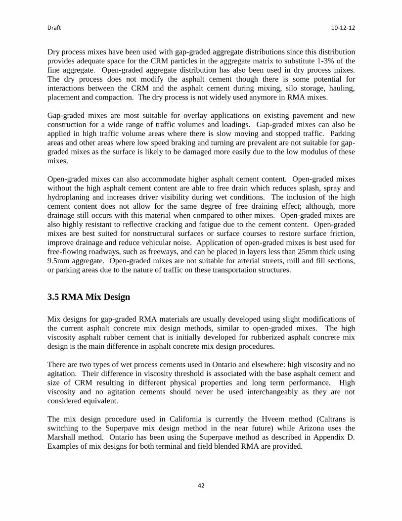
Draft 10-12-12
42
Dry process mixes have been used with gap-graded aggregate distributions since this distribution
provides adequate space for the CRM particles in the aggregate matrix to substitute 1-3% of the
fine aggregate. Open-graded aggregate distribution has also been used in dry process mixes.
The dry process does not modify the asphalt cement though there is some potential for
interactions between the CRM and the asphalt cement during mixing, silo storage, hauling,
placement and compaction. The dry process is not widely used anymore in RMA mixes.
Gap-graded mixes are most suitable for overlay applications on existing pavement and new
construction for a wide range of traffic volumes and loadings. Gap-graded mixes can also be
applied in high traffic volume areas where there is slow moving and stopped traffic. Parking
areas and other areas where low speed braking and turning are prevalent are not suitable for gap-
graded mixes as the surface is likely to be damaged more easily due to the low modulus of these
mixes.
Open-graded mixes can also accommodate higher asphalt cement content. Open-graded mixes
without the high asphalt cement content are able to free drain which reduces splash, spray and
hydroplaning and increases driver visibility during wet conditions. The inclusion of the high
cement content does not allow for the same degree of free draining effect; although, more
drainage still occurs with this material when compared to other mixes. Open-graded mixes are
also highly resistant to reflective cracking and fatigue due to the cement content. Open-graded
mixes are best suited for nonstructural surfaces or surface courses to restore surface friction,
improve drainage and reduce vehicular noise. Application of open-graded mixes is best used for
free-flowing roadways, such as freeways, and can be placed in layers less than 25mm thick using
9.5mm aggregate. Open-graded mixes are not suitable for arterial streets, mill and fill sections,
or parking areas due to the nature of traffic on these transportation structures.
3.5 RMA Mix Design
Mix designs for gap-graded RMA materials are usually developed using slight modifications of
the current asphalt concrete mix design methods, similar to open-graded mixes. The high
viscosity asphalt rubber cement that is initially developed for rubberized asphalt concrete mix
design is the main difference in asphalt concrete mix design procedures.
There are two types of wet process cements used in Ontario and elsewhere: high viscosity and no
agitation. Their difference in viscosity threshold is associated with the base asphalt cement and
size of CRM resulting in different physical properties and long term performance. High
viscosity and no agitation cements should never be used interchangeably as they are not
considered equivalent.
The mix design procedure used in California is currently the Hveem method (Caltrans is
switching to the Superpave mix design method in the near future) while Arizona uses the
Marshall method. Ontario has been using the Superpave method as described in Appendix D.
Examples of mix designs for both terminal and field blended RMA are provided.

Draft 10-12-12
43
3.5.1 Wet Process High Viscosity
To meet the quality requirements, high viscosity wet process asphalt rubber cement must meet
all appropriate asphalt specifications on the project. Special consideration should be taken to
ensure the interaction of the asphalt cement and the CRM is adequate depending on asphalt
cement source and grade, rubber type and source, percentage and gradation of rubber and the
interaction time and temperature. All of these parameters should be closely monitored
throughout mixing and during the addition to the aggregate.
For an adequate binder design, testing should be carried out to develop a design profile for all of
the specified properties which can be used later during the RMA production. This procedure is
recommended by the Rubber Pavements Association and is used by the States of California and
Arizona. The measured data from the samples tested should be taken over a 24 hour interaction
period. The design profile should report the results at a period of 45 minutes and 4 hours after
the initial interaction. The test results during a simulated overnight cool down at a temperature
of 135°C for a period of 14 hours starting at 6 hours and 22 hours after the inclusion of the CRM
should be measured to check stability. In addition, any other relevant test data in accordance
with local practice should be measured.
After testing is completed on the asphalt rubber cement during the cool down period, the cement
should be reheated and the viscosity should be measured. The design profile should also include
a list of the material sources contained in the asphalt rubber cement as well their respective
proportions and gradations. Any alterations to the proportions and/or material components
would invalidate the design profile and a new one would need to be constructed.
Both the viscosity and resilience are expected to fluctuate as the asphalt and rubber components
interact over time. The viscosity should be no less than the minimum of 1,500 cPs during the
observed interaction period and there should be no drastic differences in readings. While there is
no maximum of resilience values, a high resilience indicates a better performance.
3.5.2 Wet Process No Agitation (Terminal Blends)
Unlike high viscosity cements, no agitation cements are wet process CRM cements that do not
need to be agitated to maintain a uniform distribution of the rubber particles in the hot asphalt
cement. The ingredients of no agitation cements are often proprietary by the supplier. Despite
this, the supplier should be able to supply and certify information on the amount of CRM and
any other materials that are included in the rubberized asphalt cement. For no agitation cements,
design profiles are not required or provided since the material is stable during storage. The
quality and stability of a no agitation cement can only be verified through monitoring and testing
conducted during the time of placement for specification compliance and for separation. The
tests used for these cements are the same as for performance graded cements.
Draft 10-12-12
44
3.5.3 Rubber Mixes Using the Wet Process
If a wet process is used to manufacture the asphalt rubber cement, it is simply added into the
asphalt plant similar to conventional asphalt cement. If it is a terminal blend, it should remain
stable and no additional agitation is required as the conventional mixing in the asphalt tank is
sufficient. If the asphalt rubber cement is high viscosity, it will require mixing at the plant prior
to addition to the aggregate during the regular production process of HMA to create a RAC.
Gap-Graded RAC.
For gap-graded mixes, the CRM gradation and content in high viscosity cements slightly affect
the volumetric properties of a gap-graded mix. The substitution of a different CRM gradation in
the cement may be necessary to adjust the RMA mix volumetric to meet the requirements. If a
gap-graded mix includes only a small amount of aggregate fines, an increase in the voids in the
mineral aggregate occurs which does not create an adequate mix design. This has been observed
in binders that include relatively coarse CRM thus causing the void structure to be altered by
aggregate particles. To mitigate the situation, finer CRM particles should be used instead.
Standard mix design methods have been used to design gap-graded RMA mixes while modifying
the method slightly to increase the mixing and compaction temperatures. The mixing
temperature for the aggregate is about 140 to 165°C and when using a high viscosity binder
ranging from 165 to 205°C. The field compaction temperature is then increased to
approximately 140 to about 150°C.
No agitation binders can also be included in gap-graded mixes, exhibiting behaviour similar to
polymer-modified asphalt cement during the mix design. The binder drain down requirement
limits the amount of no agitation binder that can be included in the mix, allowing a lower amount
of design binder contents than in a high viscosity binder with the same aggregate gradation.
Open-Graded RAC
For the open-graded RAC, the viscosity is determined to be 1.2 times the optimum PG asphalt
content. The factor of 1.2 increases the PG asphalt content to accommodate for the amount of
CRM included in the binder without increasing the amount of asphalt cement used and that
provides free draining for the binder mix. In addition to determining the target high viscosity
asphalt rubber binder content, the binder drainage should also be determined at the target binder
content. To verify that the draindown is not excessive, binder drainage is evaluated at about
150°C.
No agitation binder can also be used in open-graded mixes and should be expected to behave
similarly to polymer-modified asphalt cement during the mix design. The optimum binder
content due to the inclusion of the no agitation binder will be limited by the drain down property
of the binder, falling in a range between the optimum binder contents of a PG asphalt and an
open graded RMA with a high viscosity binder.
Open-Graded RMA High Binder
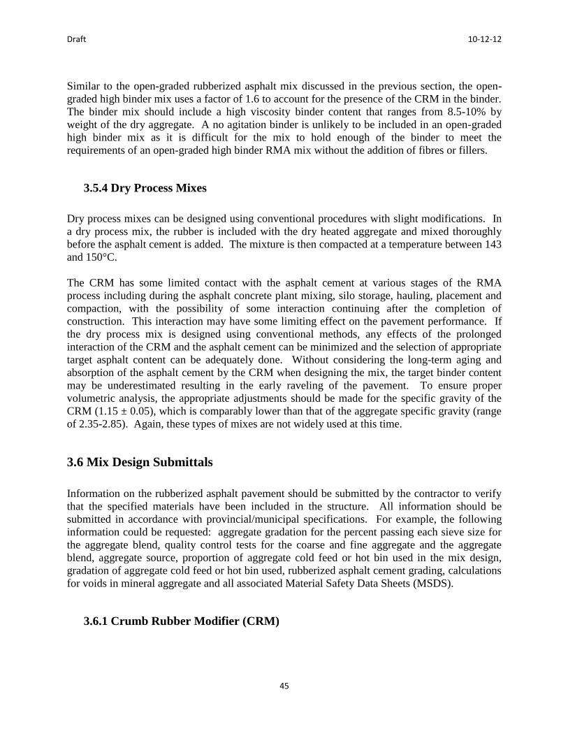
Draft 10-12-12
45
Similar to the open-graded rubberized asphalt mix discussed in the previous section, the open-
graded high binder mix uses a factor of 1.6 to account for the presence of the CRM in the binder.
The binder mix should include a high viscosity binder content that ranges from 8.5-10% by
weight of the dry aggregate. A no agitation binder is unlikely to be included in an open-graded
high binder mix as it is difficult for the mix to hold enough of the binder to meet the
requirements of an open-graded high binder RMA mix without the addition of fibres or fillers.
3.5.4 Dry Process Mixes
Dry process mixes can be designed using conventional procedures with slight modifications. In
a dry process mix, the rubber is included with the dry heated aggregate and mixed thoroughly
before the asphalt cement is added. The mixture is then compacted at a temperature between 143
and 150°C.
The CRM has some limited contact with the asphalt cement at various stages of the RMA
process including during the asphalt concrete plant mixing, silo storage, hauling, placement and
compaction, with the possibility of some interaction continuing after the completion of
construction. This interaction may have some limiting effect on the pavement performance. If
the dry process mix is designed using conventional methods, any effects of the prolonged
interaction of the CRM and the asphalt cement can be minimized and the selection of appropriate
target asphalt content can be adequately done. Without considering the long-term aging and
absorption of the asphalt cement by the CRM when designing the mix, the target binder content
may be underestimated resulting in the early raveling of the pavement. To ensure proper
volumetric analysis, the appropriate adjustments should be made for the specific gravity of the
CRM (1.15 ± 0.05), which is comparably lower than that of the aggregate specific gravity (range
of 2.35-2.85). Again, these types of mixes are not widely used at this time.
3.6 Mix Design Submittals
Information on the rubberized asphalt pavement should be submitted by the contractor to verify
that the specified materials have been included in the structure. All information should be
submitted in accordance with provincial/municipal specifications. For example, the following
information could be requested: aggregate gradation for the percent passing each sieve size for
the aggregate blend, quality control tests for the coarse and fine aggregate and the aggregate
blend, aggregate source, proportion of aggregate cold feed or hot bin used in the mix design,
gradation of aggregate cold feed or hot bin used, rubberized asphalt cement grading, calculations
for voids in mineral aggregate and all associated Material Safety Data Sheets (MSDS).
3.6.1 Crumb Rubber Modifier (CRM)

Draft 10-12-12
46
In terms of CRM, the following information would normally be required: supplier(s) and type of
scrap tire and natural CRM used, gradation of each type of CRM material used from each
supplier, scrap tire and natural CRM percentage by total mass of the asphalt-rubber blend from
each supplier, laboratory tests results for the specified test parameters and Material Safety Data
Sheets (MSDS).
3.6.2 Asphalt Rubber Cement
In terms of the asphalt rubber cement, the following information would generally be required:
base asphalt PG binder grade, supplier, identification and test results demonstrating
conformance, percentage of the combined blend of asphalt by total mass of asphalt-rubber
binder, percentage of asphalt modifier by mass of asphalt-rubber binder, selected asphalt rubber
content modified as appropriate for high viscosity binders, design profile, minimum interaction
time and temperature and Material Safety Data Sheets (MSDS).
The design profile for the high viscosity cements provides all the relevant information on the
asphalt cement design in order to ensure that the asphalt cement complies with the project
specification. The design profile includes information on the compatibility of the components,
and the quality and stability of the asphalt rubber cement properties. The viscosity and the
resilience of the cement are the more important information as they are indicators of the
performance of the asphalt cements. The profile also lists the results of the specification
compliance tests conducted on samples of the cement during a 24-hour period and compares the
results to the expected properties.
3.6.3 Anti-Strip Additives
If an anti-strip additive is used in the mix, the name of the product, manufacturer, manufacturer’s
designation and proposed rate, location, method of addition and the Material Safety Data Sheets
(MSDS) is required.
3.7 Typical Specifications
The detailed specification for rubberized asphalt products is given in Appendix C. This section
summarizes the important aspects of the specifications currently used.
The RMA mix designs are performed in accordance with both the CRM requirements and the
respective Superpave mix type requirements. For the wet process-terminal blend, the mix is
designed to incorporate RMA in place of PGAC. For the wet process-terminal blend Rubberized
Asphalt Cement (RAC), it is produced by the PGAC supplier at their asphalt terminal. For the
wet process-field blend, the mix is designed to incorporate RMA in place of PGAC. Wet
process-field blend RMA is produced at the hot mix asphalt plant using a field blending plant.
The Superpave 12.5FC 2 R-Gap Graded mix design and JMF are done according to the

Draft 10-12-12
47
requirements specified in the MTO specifications. For mix design purposes, the RAC is
produced in the laboratory according to the following procedure: heat up the base PGAC to
180oC, add 18-20% CRM by weight of the PGAC while continuously blending the compound,
and continue blending the RAC for 45 minutes at 180oC.
The specifications describe the need for the contractor to submit a plan to ensure the CRM will
be available and that it meets all the requirements. The basic information on the CRM supplier’s
name, address, CRM gradation, materials safety data sheet (MSDS), method and equipment used
to mix CRM into mix need to be included. It also presacribes the CRM dosage, RAC reaction
time, mixing temperatures, RAC storage conditions, and any need for agitation. Special
attention is noted to prevent swelling of the briquettes during the mix design, ensure the CRM is
homogeneously distributed in the RMA, that there is no pick-up during compaction of the RMA
and information explaining how the CRM was ground (i.e. cryogenic or ambient ground or
both). Finally, a letter from the CRM supplier indicating that the CRM they are supplying is
produced in the province from scrapped tires should be provided.
Materials for the RMA should conform to the specifications and it is the Contractor’s
responsibility to identify a facility to produce the mixes in accordance with the supplier’s
instructions for the use of their materials. The Contractor is responsible for obtaining from the
suppliers any and all information required for the proper preparation, handling, storage and use
of their materials as well asobtaining materials, producing mixes, transportation, storage and use
of all materials and ensuring the RMA is produced to prevent any deleterious effects to the
finished product.
The CRM is processed from whole passenger vehicle tires. Use of uncured or devulcanized
rubber will not be permitted. CRM will be ambient or cryogenic ground rubber, or both. The
CRM must be produced in the province from tires scrapped in the province. The specifications
also include requirements for gradntion, specific gravity and more. Additional testing being
considered by the MTO on the crumb rubber is included in Appendix F.
Wet-terminal blend RAC is produced as a Type III Asphalt Rubber Cement according to ASTM
D6114. CRM dosage by mass of wet-terminal blend RAC normally range from 10% to 15%.
Wet-field blend RAC (after reaction) can be found in Table R4 of the specifications (see
Appendix C). CRM dosage by mass of wet-field blend RAC is normally 18% to 20%.
When the RAC supplier specifies a CRM gradation with additional restrictions, the CRM must
meet the RAC supplier’s gradation requirements. The CRM material, PGAC and any anti-
stripping additives required must be compatible to ensure a good dissolution and reaction time.
If an anti-stripping agent is to be incorporated into the mix, the Contractor should contact and
consult with each supplier to determine whether or not the proposed anti-stripping agent is
compatible with the RMA or RAC or both.
The Contractor must contact OTS a minimum of 6 weeks prior to paving Superpave 12.5FC 2 R-
Gap Graded to coordinate delivery and operation of the field blending plant. OTS contact
information is provided in this special provision. Further, the Contractor must construct the trial
section full width including shoulders. This is described in more detail in Appendix C.

Draft 10-12-12
48
For acceptance, all CRM must meet the gradation requirements specified in accordance with
ASTM D5644. Acceptance of Rubber Modified Asphalt (RMA) and pay adjustment of the
RMA containing RAC-terminal blend will be determined in accordance to the respective mix
type HMA requirements specified elsewhere in the Contract Documents. Acceptance of the
RAC wet-terminal blend will be determined according to the respective requirements for the
PGAC grade specified and the RAC wet-terminal blend shall meet the Type III Asphalt Rubber
Binder requirements of ASTM D6114. Acceptance of the TAC wet-field blend will be in
accordance with the specification.
3.8 Summary
The design of rubberized asphalt concrete requires a number of tests to ensure compliance with
the specified properties and degree of quality. The process can become quite complex due to the
number of types of asphalt binders that could be implemented and the mix types that can be
created. The design is ultimately determined based on the proposed use of the product and the
desired properties. As with any project, all the required documentation in accordance with the
local provincial or municipal specifications should be submitted to ensure the RMA will meet all
of the quality standards.
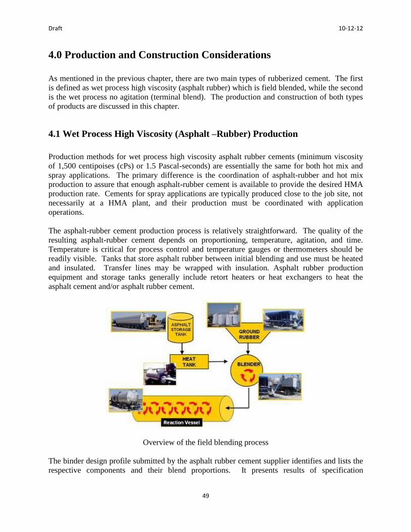
Draft 10-12-12
49
ChapterCapter 4 Production and ConstructionThe production
4.0 Production and Construction Considerations
As mentioned in the previous chapter, there are two main types of rubberized cement. The first
is defined as wet process high viscosity (asphalt rubber) which is field blended, while the second
is the wet process no agitation (terminal blend). The production and construction of both types
of products are discussed in this chapter.
4.1 Wet Process High Viscosity (Asphalt –Rubber) Production
Production methods for wet process high viscosity asphalt rubber cements (minimum viscosity
of 1,500 centipoises (cPs) or 1.5 Pascal-seconds) are essentially the same for both hot mix and
spray applications. The primary difference is the coordination of asphalt-rubber and hot mix
production to assure that enough asphalt-rubber cement is available to provide the desired HMA
production rate. Cements for spray applications are typically produced close to the job site, not
necessarily at a HMA plant, and their production must be coordinated with application
operations.
The asphalt-rubber cement production process is relatively straightforward. The quality of the
resulting asphalt-rubber cement depends on proportioning, temperature, agitation, and time.
Temperature is critical for process control and temperature gauges or thermometers should be
readily visible. Tanks that store asphalt rubber between initial blending and use must be heated
and insulated. Transfer lines may be wrapped with insulation. Asphalt rubber production
equipment and storage tanks generally include retort heaters or heat exchangers to heat the
asphalt cement and/or asphalt rubber cement.
Overview of the field blending process
The binder design profile submitted by the asphalt rubber cement supplier identifies and lists the
respective components and their blend proportions. It presents results of specification

Draft 10-12-12
50
compliance tests on laboratory samples of the subject cement taken over a 24-hour interaction
period and indicates the expected pattern of the interaction properties. The design profile should
be treated as a guide rather than as a specification, but major departures may indicate production
issues that should be addressed immediately. The following table presents an example of a
binder design profile and specification requirements.
Example of an AR Binder Design Profile
AR Binder Design Profile
Test Performed
Minutes of Reaction 45 minutes
Specification
Limits
45
90
240
360
1,440
Viscosity, Haake at
190°C, Pa.s, (10-3), or
cP (*See Note)
2400
2800
2800
2800
2100
1500 – 4000
Resilience at 25°C, %
Rebound (ASTM
D5329)**
27
--
33
--
23
18 Minimum
Ring & Ball Softening
Point, °C (ASTM D36)
59.0
59.5
59.5
60.0
58.5
52 – 74
Cone Pen. at 25°C,
150g, 5 sec., 1/10 mm
(ASTM D217)
39
--
46
--
50
25 – 70
Crumb rubber modifier (CRM) is typically packaged in one ton super sacks that should be
clearly labeled and stored to prevent loss or damage. The CRM is fed into a weigh hopper for
proportioning along with the asphalt cement and other additives such as extender oil, if used.
Super sacks of CRM

Draft 10-12-12
51
CRM bins
Equipment for component feeding and blending may differ among asphalt rubber types and
manufacturers, but the processes are similar. The component materials are metered into high
shear blending units to incorporate the correct proportions of extender oil, if used, and CRM into
the paving grade asphalt. The blending units thoroughly mix the CRM into the hot asphalt and
the blend is pumped into a heated tank where the asphalt rubber interaction proceeds.
CRM blending unit
Augers are needed to agitate the high viscosity asphalt rubber inside the tanks to keep the CRM
particles well dispersed; otherwise, the particles tend either to settle to the bottom or float near
the surface. Agitation can be verified by periodic observation through the port where the auger
control is inserted.

Draft 10-12-12
52
CRM reaction vessel
Hand held rotational viscometers (Haake, Rion, or equivalent) are used to monitor the rotational
viscosity of the asphalt rubber interaction over time for quality control and assurance. Before
any asphalt rubber cement can be used for hot mix production or spray application, compliance
with the minimum viscosity requirement must be verified using an approved viscometer. As
long as the viscosity is in compliance and the interaction has proceeded for at least 45 minutes,
the asphalt rubber cement may be used.
Measuring viscosity of field blends using a viscometer
4.1.1 Holdover and Reheating
If an asphalt rubber material is not used within 4 hours after the 45-minute reaction period, most
agencies require that heating be discontinued. Sometimes the asphalt rubber cement must be
held overnight. The rate of cooling in an insulated tank varies, but reheating is required if the
temperature drops below 177 to 191ºC. A reheat cycle is defined as any time that an asphalt
rubber cement cools below its designated viscosity measurement temperature and is reheated.

Draft 10-12-12
53
Two reheat cycles are allowed, but the asphalt rubber cement must continue to meet
requirements, including the minimum viscosity.
The asphalt and rubber continue to interact at least as long as the asphalt rubber remains liquid.
The rubber breaks down (is digested) over time, which reduces viscosity. Up to 10 % more
CRM by cement mass can be added to restore the viscosity to specified levels. The resulting
asphalt rubber blend must be interacted at the designated temperature for 45 minutes and must
meet the minimum viscosity requirement before it can be used. Most specifications have
specific requirements for transferring holdover cement material between projects and Agencies.
For Ontario’s specifications, please refer to Appendix C.
4.1.2 Documentation
A Certificate of Compliance (COC) is required for every cement constituent as well as for the
finished asphalt rubber cement. The COCs must include test results that show conformance of
the materials to the respective special provisions, including chemical composition of the scrap
tire as applicable. COCs for the component materials delivered to the site of the asphalt rubber
cement blending operation should be provided to the engineer, inspector and/or project staff.
Representatives of the owner typically sample the individual components and blended asphalt
rubber materials at the blending site for testing and acceptance.
A copy of the approved Asphalt Rubber Binder Design Profile that includes results of specified
laboratory tests and proportions of each component must be available at the asphalt rubber
blending site.
A log of Asphalt Rubber Cement Production should also be maintained for each project. For
each batch of asphalt rubber produced, the log should list the weights of each component used,
the reaction start time, and the results of each viscosity test performed, including the time and
asphalt rubber cement temperature and the time when the batch was metered into the AC plant.
The production log should also include all holdovers and reheat cycle information including the
time that heating was discontinued, the time that reheating began and corresponding asphalt
rubber cement temperature, CRM addition weight and time if applicable, and subsequent
viscosity test results. This is not yet required by the MTO.
4.1.3 Sampling and Testing Requirements
Frequency of sampling and testing may vary depending on the nature of the materials, project
size, and available resources. Aside from minimum requirements, additional sampling is
recommended whenever changes in any material or its behavior are observed. Sampling during
production and construction is relatively easy and inexpensive, and it is rarely necessary to test
every sample obtained. Suggested minimum requirements for quality control (QC) and quality
assurance (QA) or acceptance sampling and testing are presented in the Table below.

Draft 10-12-12
54
Suggested Minimum Sampling and Testing Requirements
Minimum Sampling and Testing Requirements
Material QC Sampling & Testing QA Sampling & Testing
CRM
Chemical
composition each
250 tons
Once per project
for compliance CRM
Gradation &
physical properties
each 10,000 pounds
Once per project
for compliance
Paving
Asphalt
Once per project
for compliance
Once per project
for compliance
Asphalt
Modifier
Once per project
for compliance
Once per project
for compliance Asphalt
Rubber
Cement
Viscosity every hour
One gallon per batch
and after each reheat
cycle
Sample one gallon
per batch and after
each reheat cycle
Test one gallon per
day for compliance RMA Mixture
Morning and afternoon daily Gradation, cement content For Gap-Graded mixes, measure Rice and lab compacted air voids
One sample daily
Gradation, cement
content For Gap-Graded
mixes, measure Rice and
lab compacted air voids
RMA
Mixture Lifts
≥ 38mm
thick
In-place compaction
Record pavement cores
taken per day
For example, agencies such as Caltrans and Arizona DOT, require the Contractor (typically the
asphalt rubber cement producer) to sample the asphalt rubber from the feed line into the AC
plant and measure the viscosity at least every hour during AC production. At least one gallon of
asphalt rubber cement should be wasted to assure that the sampling valve is clear, and the sample
to be tested should be poured into a clean, dry one-gallon container that can be sealed and clearly
labeled for possible additional laboratory testing after field viscosity measurements are
completed.

Draft 10-12-12
55
Viscosity for the field blend is a go/no-go test
At least one viscosity test is required to establish compliance for each asphalt rubber batch and
holdover load. The Engineer or Inspector may wish to be notified when the tests will be
performed. Agencies such as Caltrans and Arizona DOT require that results of all viscosity tests
performed, including the time and asphalt rubber cement temperature, be submitted to the
Engineer on a daily basis. This is good practice for any project with high viscosity cement.
MTO follows these practices as well.
Rotational viscosity is the go/no-go field test that governs use of the asphalt rubber cement. A
4.4 litre (1 gal) can is used to provide adequate clearance from the sides and bottom of the
container, and should be 75-85% filled with the cement. The Caltrans Asphalt Rubber Usage
Guide includes a description of the Caltrans field test method using the old style analog gauges,
and suggested revisions [Caltrans, 2006]. Either method can be used with similar results, but
neither addresses the new style digital readout gauges or how to control cement temperature
during viscosity measurement. Test equipment, such as a hot plate, gas burner or stove, should
be added for temperature control. An ASTM method is in development which is based on the
proposed Caltrans laboratory procedure.
4.2 Terminal Blends
The wet process no agitation cements may be manufactured by different methods and are
governed by different specifications than the high viscosity asphalt rubber cements described
herein. No agitation cements are much like polymer modified asphalt and the resulting hot
mixes are much more similar to conventional HMA. An example of the specification for the
terminal blends are given in Appendix C. These products are provided by the binder supplier
and generally come with a certificate of compliance certifying the material meets specifications.
4.3 Production of AR Hot Mixes
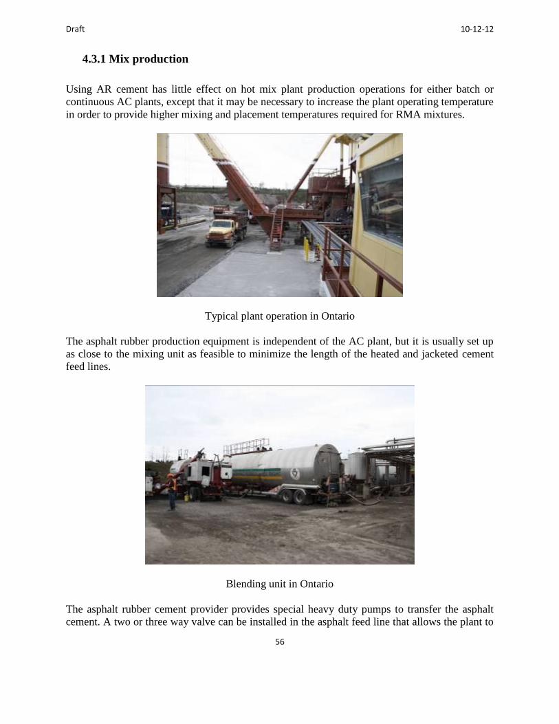
Draft 10-12-12
56
4.3.1 Mix production
Using AR cement has little effect on hot mix plant production operations for either batch or
continuous AC plants, except that it may be necessary to increase the plant operating temperature
in order to provide higher mixing and placement temperatures required for RMA mixtures.
Typical plant operation in Ontario
The asphalt rubber production equipment is independent of the AC plant, but it is usually set up
as close to the mixing unit as feasible to minimize the length of the heated and jacketed cement
feed lines.
Blending unit in Ontario
The asphalt rubber cement provider provides special heavy duty pumps to transfer the asphalt
cement. A two or three way valve can be installed in the asphalt feed line that allows the plant to

Draft 10-12-12
57
switch between using asphalt rubber or regular asphalt cement. For drum plants, the asphalt
rubber producer is required to use a flow meter that interlocks the cement feed with the aggregate
feed.
Photo of field blended asphalt rubber
RMA production rates may be reduced somewhat from HMA production due to higher cement
content and the lower rubber cement production rate. However, planning and coordination
between the asphalt rubber cement producer and the AC plant operator can be used to minimize
impacts on RMA production. The cement supplier can, in many cases, arrange to use more or
larger storage and interaction tanks and schedule materials deliveries and asphalt rubber blending
operations to expedite production of asphalt rubber cement and mix.
4.3.2 Inspection and Troubleshooting of the RMA Mixture
The primary change to the Plant Inspector’s normal duties is the addition of monitoring the
asphalt rubber production and viscosity results and sampling the asphalt rubber cement and its
components. As mentioned earlier, an Asphalt Rubber Cement Production Log and Testing Log
should contain the pertinent information, and should be available for inspection. The Inspector
should obtain at least one 4.4 litre (1 gal) sample from each batch of asphalt rubber cement
produced for the project to test for compliance with specification limits, and additional samples
if any changes in appearance or behavior are observed.
The normal activities related to plant inspection for AC production remain the same and include
the following items, along with close attention to temperature:
Observing aggregate storage and handling and plant operations

Draft 10-12-12
58
Basic sampling and testing procedures for checking aggregate and RMA characteristics;
Verifying that the correct mixture is being produced according to the design
and in compliance with specifications, etc.
Sampling the aggregate
Sampling the asphalt rubber
Sampling the mix

Draft 10-12-12
59
4.3.3 Importance of Temperature
The key to quality in producing asphalt rubber materials and constructing asphalt rubber
pavements is temperature control in all aspects of the work. Asphalt rubber materials need to be
produced and handled at somewhat higher temperatures than conventional bituminous materials
and mixtures because they are stiffer at the typical mixing and compaction temperatures.
Temperature is critical to:
Asphalt rubber cement manufacture
RMA hot mix production RMA delivery RMA placement RMA compaction
It is important to closely monitor temperature of the materials during all phases of asphalt rubber
cement and mixture production and construction. The Inspector should have appropriate
equipment for checking the temperature of asphalt rubber cement and hot mix, including surface
and probe type thermometers that can also measure ambient air temperature, and a heat gun. The
asphalt rubber blending and storage tanks should also be equipped with readily visible
thermometers.
Checking the mix temperature
Temperature measuring devices

Draft 10-12-12
60
Both the plant and field inspectors should visually inspect the RMA in the haul truck bed for
signs of any problems with the mix and check mix temperature. RMA temperature should be
measured with a thermometer that has a probe at least 150mm (6 in) long, by sticking the full
depth of the probe into the mix. Surface readings are not an accurate indicator. If only a heat
gun is available, it will be necessary to measure the temperature of the RMA as it is flows out of
the plant discharge chute into the haul truck.
Whenever any type of RMA mixture problem is suspected, the Inspector should obtain samples
immediately and have them tested immediately for gradation and asphalt rubber cement content.
In some cases, it may be necessary to check the voids of the compacted hot mix specimens.
The Inspector should enter a full description of the problem observed and subsequent activities in
the daily project log, and immediately report these observations to the Engineer. Test results
should be relayed to the Engineer immediately upon receipt. Some of the potential “trouble”
signs to watch for in the mix are as follows:
Segregation: Particle size segregation may be difficult to identify in some coarse
gap-graded mixtures. There are few fines present and that can sometimes make the
RMA appear segregated even if it is not. Identify the affected truckloads and
corresponding placement areas, take samples and test gradation and cement content to
verify. It is also recommended that, if possible, samples of RMA that do not appear
segregated should be taken from the same truckload, for comparison. Temperature
segregation (hot or cold spots) may be checked with a heat gun or with an infrared
camera. The primary concern is differences rather than exact values.
Blue smoke: The mix is too hot.
White smoke: Steam, not smoke, which indicates too much moisture in the mix. This
means that the aggregate was not dried enough prior to mixing with asphalt rubber
cement. This may cause the RMA mix to become tender and may contribute to
compaction problems.
Dull, flat appearance: Indicates low asphalt rubber cement content and/or excessive
fines (minus 0.075 mm (No. 200) sieve size). Localized areas of dullness may
indicate insufficient mixing of the asphalt rubber cement and aggregates, or mix
segregation. Take samples and test for gradation and cement content.
Slumped and shiny: High asphalt rubber cement content. RAC-O, and especially
RAC-O (HB) mixtures, may look this way and still meet SSP requirements, so this is
not always a problem. An old descriptive term for this is “wormy,” because the mix
seems to almost crawl when watched. Look in the truck bed for cement draindown
and take and test samples for asphalt rubber cement content and gradation.

Draft 10-12-12
61
4.3.4 Safety Considerations
Safety is always a consideration when working with hot materials. Conventional HMA mixtures
are hot enough to cause burns, and so are asphalt rubber cements and RMA materials. Personnel
should wear appropriate protective gear including, but not limited to, gloves made for handling
hot samples and suitable eye protection.
4.4 Hot Mix (RMA) Paving Equipment
Conventional equipment is used to place and compact RMA materials. The field inspector
should confirm that the necessary paving and compaction equipment is on site before any asphalt
rubber hot mix is shipped from the AC plant.
4.4.1 Haul Trucks
Any type of trucks that are customarily used for transporting AC may be used, including
conventional end or bottom dumps, or horizontal discharge (live bottom). Trucks hauling RMA
mix should be tarped to retain heat during transport.
Haul truck receiving mix in Ontario
4.4.2 Material Transfer Vehicle (MTV)
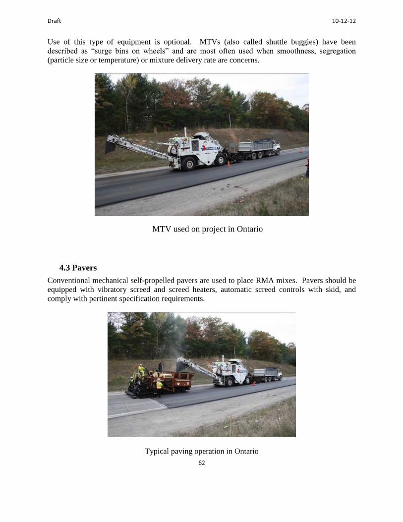
Draft 10-12-12
62
Use of this type of equipment is optional. MTVs (also called shuttle buggies) have been
described as “surge bins on wheels” and are most often used when smoothness, segregation
(particle size or temperature) or mixture delivery rate are concerns.
MTV used on project in Ontario
4.3 Pavers
Conventional mechanical self-propelled pavers are used to place RMA mixes. Pavers should be
equipped with vibratory screed and screed heaters, automatic screed controls with skid, and
comply with pertinent specification requirements.
Typical paving operation in Ontario

Draft 10-12-12
63
4.4.4 Rollers
Rubber tired rollers are not appropriate for compacting RMA mixes because of excessive pick
up of the mixture by the tires. Rollers for RMA must be steel-wheeled (drum), and must be
equipped with pads and a watering system to prevent excessive pick-up. It may sometimes be
necessary to add a little soap or other surfactant to the watering system.
Rolling operation
RAC-G mixtures are likely to require more compaction effort than DGAC due to the
relatively coarse nature of the aggregate skeleton. Minimum recommended roller weight is
8 tonnes; pup rollers cannot provide sufficient compaction. The types of rollers include:
Breakdown roller with vibratory capability: It is strongly recommended that
two breakdown rollers be used to keep up with the paver, especially if paving
width exceeds 3.7m.
Intermediate roller: If not of equal or greater width than the breakdown
roller(s), two intermediate rollers should be required.
Finish roller: May be vibratory or static, but use the static mode for
finishing Standby roller: One with vibratory capability should be on site and shall be required if
only one breakdown roller is available.

Draft 10-12-12
64
4.5 Final Preparation for Paving
Surface preparation must be completed prior to RMA production or spray application. This
includes customary items such as removal and replacement of failed pavement and pothole
repair (patching), milling or grinding for smoothness and/or to restore or adjust profile, crack
filling and/or sealing.
4.5.1 Patching
Patching should be performed using standard good practice and DGAC. Do not overfill
cracks, as excess sealer/filler will cause bumps in the overlay and may migrate up through the
RMA mat during compaction and to create “fat spots.” Fill ruts as necessary. If a leveling
course is required, use a fine DGAC mix. Immediately prior to mixture delivery, the surface
should be swept and tack coat applied.
4.5.2 Tack Coat
A tack coat should be uniformly applied to lightly cover the entire pavement surface to be
overlaid. Tack coat may consist of paving grade asphalt or emulsified asphalt. Area of tack
application should be limited to what will be paved over on that day. However, tack coat is
not required when an asphalt rubber interlayer will be placed prior to overlaying, and is not
usually recommended when RMA will be placed directly on a new pavement. The types of
tack coats used include:
Paving Grade Asphalt Cement: Unmodified paving grade asphalt is preferred as the
tack for RMA mixes. Asphalt tack must be hot enough to spray an overlapping fan
pattern that provides a uniform application. The distributor truck must have a heater
to maintain asphalt temperature and consistency for spray application. The
application rate must be properly controlled to avoid bleeding (too high) or
delamination (too low). Any defective or plugged nozzles must be corrected
immediately.
Emulsified Asphalt: Recommended application rate is 0.23 to 0.45 l/m2 ( 0.05 to 0.1
gal/yd2) residual, depending on the condition of the existing surface. Caution should
be used when ambient and pavement temperatures are marginally cool and emulsion
tack coats are used. Emulsion must “break” (i.e. turn from dark brown to black as the
suspended asphalt droplets separate from the water) and the water must evaporate
prior to paving. Otherwise, the remaining water in the emulsion will turn to steam
and rise up through the mat. This prevents the tack from establishing the intended
bond with the new pavement and the excess moisture may also cause a tender spot in
the mix during compaction. Water trapped between pavement layers may cause
stripping and delamination. Cold or damp site conditions and lack of sun slow

Draft 10-12-12
65
evaporation and may delay paving operations.
4.6 Hot Mix Delivery
The same good practices recommended for conventional hot mix delivery should be applied
to RMA materials, along with special attention to temperature. Any type of conventional AC
haul truck can be used to transport RAC. However, use of bottom dumps and windrows is not
recommended when air and pavement surface temperatures are marginally cool. It is critical
that the RMA does not cool below the minimum laydown temperature of 138 to 149ºC,
depending on owner agency and temperature at paving site during transport. Tarps are needed
to maintain acceptable mixture shipment temperatures ranging from 143 to 163ºC..
Hot mix delivery
4.6.1 Coordinating Mix Delivery and Placement
Coordination and balance of cement and mix production with mix delivery, placement, and
compaction operations are essential to achieving a smooth finished pavement with a pleasing
appearance, which are the two factors that motorists reportedly consider the most important
indicators of pavement quality.
The paver should never have to stop due to lack of material. If it stops on the new mat, the
result will be either a bump or depression that cannot be removed by rolling. If it pulls off the
mat, it may be necessary to construct a transverse joint. A long line of haul trucks waiting to
access the paver usually means that some loads will cool too much to be used. Material
transfer vehicles can be used to reduce adverse impacts of irregular mix delivery.
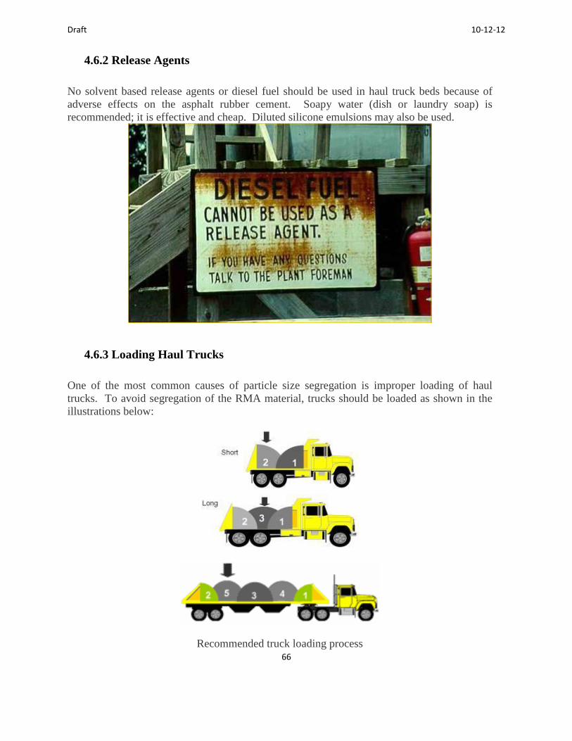
Draft 10-12-12
66
4.6.2 Release Agents
No solvent based release agents or diesel fuel should be used in haul truck beds because of
adverse effects on the asphalt rubber cement. Soapy water (dish or laundry soap) is
recommended; it is effective and cheap. Diluted silicone emulsions may also be used.
4.6.3 Loading Haul Trucks
One of the most common causes of particle size segregation is improper loading of haul
trucks. To avoid segregation of the RMA material, trucks should be loaded as shown in the
illustrations below:
Recommended truck loading process

Draft 10-12-12
67
4.6.4 Unloading Hot Mix into a Paver Hopper
The haul truck should be centered and backed up to the paver, but should stop just short of
contacting the push rollers on the front of the paver. After the truck releases its brakes, the
paver should move forward to pick up and push the truck forward, instead of the truck
bumping the paver. This method helps to minimize screed marks and roughness. End dumps
and, if used, live bottom trucks should raise their beds slightly so that the mix slides up
against the closed tailgate, then open the gates to discharge the mix in a single mass. This
“floods” the paver hopper and helps to minimize potential for mix segregation.
4.6.5. Unloading Hot Mix into a Material Transfer Vehicle
MTVs also have a front hopper to receive the mix and eliminate the problem of bumping the
paver. The same method of discharge should be used to “flood” the MTV hopper as a paver
hopper.
4.6.6 Load Tickets
Load tickets should be collected when the mix is discharged from the haul truck to document
quantities delivered and used. Yield calculations are typically used to verify overall thickness

Draft 10-12-12
68
based on total tonnage and area paved. However, in-place thickness of randomly selected
cores should also be measured as a check.
4.7 Hot Mix Placement
Placement of asphalt rubber materials or any HMA materials requires good paving practices.
Temperature is critical for proper placement of all HMA materials. Asphalt rubber cements
are stiffer than conventional paving asphalt at the customary placement and compaction
temperatures, so time available for compaction of modified materials is typically shorter than
for conventional dense graded mixtures. How much shorter depends on a number of variables
that are discussed in the section on compaction.
As for conventional dense-graded mixes, asphalt rubber paving materials should not be placed
during rain or when rain is imminent. If site conditions are wet, windy, or too cold, placement
should be delayed until conditions improve. Otherwise, expect significant problems in
achieving adequate compaction of hot mixes. Weather conditions may change during the
paving operation. If necessary, paving should be stopped until conditions improve.
Caltrans specifications for RAC-G specify minimum atmospheric and pavement surface
temperatures of 13ºC and rising for mixture placement. Other agencies such as Ontario allow
a slightly lower ambient temperature of 10ºC and rising for placement, but require that
breakdown compaction start before the mat temperature drops below 143ºC. Placement at
minimum ambient temperatures is not recommended because time available for compaction is
very limited and leaves no margin for circumstance or error, resulting in inadequate
compaction. When feasible, it is recommended that the minimum ambient temperature
requirement for placement be increased to 18ºC. Because of the importance of temperature in
achieving adequate RMA compaction, operating in the mid to upper end of specified
temperature ranges is strongly recommended.
4.7.1 Paver Operations
Paver operations for RMA should not differ from those commonly used for conventional
HMA, except perhaps for paying closer attention to the temperature of the mix in the hopper.
It is important to the quality of the finished product that the paver be operated to minimize
starting and stopping. The importance of coordinating mix delivery with placement cannot be
overemphasized.
A consistent paver speed, even if relatively slow, helps maintain a uniform head of material
and to control thickness. Care should be taken to dump (fold) the paver wings before mix
collected in the corners cools enough to form chunks. However, wings should never be
dumped into an empty hopper. Slat conveyors should not be allowed to run empty or nearly
so.

Draft 10-12-12
69
Stress the importance of coordination
4.7.2 Raking and Handwork
Asphalt rubber mixtures are not particularly amenable to raking or handwork. The relatively
coarse RAC-G aggregate gradation and stiffer cement make handwork a problem and may
affect the appearance of joints. Luting the joints segregates the mix and interferes with joint
compaction. Handwork and raking of RMA should be minimized, but, if necessary, should be
performed immediately before the mix cools. The higher asphalt rubber cement content of
RAC-O-HB makes raking and handwork a little easier, but it should still be kept to a
minimum. Do not broadcast the mix: it is no longer considered to be good practice.
The lack of fines in the gap- and open-graded mixes can create a somewhat rough and open-
looking texture, even when placed by machine. RMA placed by hand may not provide a
pleasing appearance even if the workmanship is excellent and the best practice is applied.
4.7.3 Joints
HMA joints are typically defined as longitudinal or transverse, cold or hot. Longitudinal
joints are most likely to be cold joints. Butt joints are most typical and the practices presented
apply to those. Some agencies have adopted wedge joints and/or skewed joints that are not
discussed in this Guide; there may be some issues with using wedge joints for RMA mixes.
To provide a good bond with the adjacent pavement, remove any loose material and tack the
vertical edge prior to placing hot mix. To minimize the need for raking, it is important to set
both the screed overlap and height carefully on the adjacent pass. The screed should overlap

Draft 10-12-12
70
the cold material by about 25 to 38 mm (1 to 1.5 in). The screed should be set above the
elevation of the cold side by approximately 6.4 mm (1/4 in) for each 25 mm (1 in) of
compacted pavement thickness being placed. Roll from the hot side of the longitudinal joint,
not the cold side, to make a tight joint.
Compacted thickness of RMA is generally between about 25 mm (1 in) and 64mm (2.5 in),
which typically yields height differences between adjacent paver passes of about 08 to 17 mm
(.3 to .65 in). Since lack of fines makes it difficult to feather the coarse-graded RAC-G
mixtures, some raking may be unavoidable, but should be kept to the minimum necessary.
Extra material should be raked onto the hot side, not the cold.
If the mix is placed by hand rather than machine, the height difference for compaction should
be increased to 9.5mm (3/8 in) for each 25mm (1 in). The height difference may vary among
mixes, so experience and engineering judgment should be used as appropriate.
Transverse joints may be hot or cold. Hot joints should be treated the same as conventional
DGAC, but the RMA mix will stiffen more quickly. Cold joints should be treated as
described for longitudinal joints. Most often, transverse joints are constructed at the end of
the paving day or when a lane is finished, using a bulkhead or Kraft paper to provide a
vertical butt joint. If the paver runs out the mix, the joint should be constructed where the full
compacted thickness is available, and the rest of the mix placed past that point should be
removed and wasted. Ideally, transverse joints should be rolled in a transverse direction, but
this is usually not practical and rarely done. Transverse joints are generally rolled
longitudinally.
4.8 Hot Mix Compaction
Compaction is essential to the performance and durability of any asphalt pavement including
asphalt rubber mixtures. The best materials, mix designs, and placement techniques cannot
compensate for adverse effects that result from poor compaction during construction.

Draft 10-12-12
71
Typical paving operation showing compactor near the paver.
The coarse aggregate structure and stiff asphalt rubber cements in RAC-G mixes often require
more compaction effort than conventional DGAC. Compaction depends primarily on
temperature and compactive effort. Breakdown compaction of RAC-G mixtures must be
performed in the vibratory mode, and it is advisable to obtain at least 95% of the required
density during breakdown rolling.
However, vibratory compaction is not used for open-graded mixtures. There are no
compaction requirements for open-graded mixes. These are typically placed as surface
courses in thin lifts about 25 to 30 mm (1 to 1.2 in) thick. Compaction is achieved with a few
passes by rollers operating in the static mode.
4.8.1. Temperature Requirements
According to Caltrans specifications for RAC-G, if the atmospheric and pavement surface
temperatures are less than 18ºC then breakdown compaction must be completed before the
mat temperature drops below 127ºC. For site temperatures with temperatures of 18ºC and
greater, breakdown compaction must be completed before the mat temperature drops below
121ºC. Regardless of the specification used, it is strongly recommended that breakdown
compaction of RAC- G should be completed before the temperature of the RMA mat drops
below 138ºC.
It is also recommended that mat temperature be closely monitored during placement and
compaction, and that adjustments be made as needed to speed up the compaction process. It
may be necessary to add a second breakdown roller. Inability to perform breakdown rolling
within the temperature range specified may be cause to terminate paving operations and reject
loads. In addition, vibratory rolling below the minimum breakdown rolling temperature
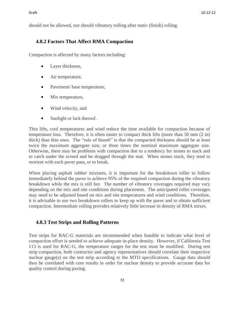
Draft 10-12-12
72
should not be allowed, nor should vibratory rolling after static (finish) rolling.
4.8.2 Factors That Affect RMA Compaction
Compaction is affected by many factors including:
Layer thickness,
Air temperature,
Pavement/ base temperature,
Mix temperature,
Wind velocity, and
Sunlight or lack thereof.
Thin lifts, cool temperatures and wind reduce the time available for compaction because of
temperature loss. Therefore, it is often easier to compact thick lifts (more than 50 mm (2 in)
thick) than thin ones. The “rule of thumb” is that the compacted thickness should be at least
twice the maximum aggregate size, or three times the nominal maximum aggregate size.
Otherwise, there may be problems with compaction due to a tendency for stones to stack and
to catch under the screed and be dragged through the mat. When stones stack, they tend to
reorient with each paver pass, or to break.
When placing asphalt rubber mixtures, it is important for the breakdown roller to follow
immediately behind the paver to achieve 95% of the required compaction during the vibratory
breakdown while the mix is still hot. The number of vibratory coverages required may vary
depending on the mix and site conditions during placement. The anticipated roller coverages
may need to be adjusted based on mix and site temperatures and wind conditions. Therefore,
it is advisable to use two breakdown rollers to keep up with the paver and to obtain sufficient
compaction. Intermediate rolling provides relatively little increase in density of RMA mixes.
4.8.3 Test Strips and Rolling Patterns
Test strips for RAC-G materials are recommended when feasible to indicate what level of
compaction effort is needed to achieve adequate in-place density. However, if California Test
113 is used for RAC-G, the temperature ranges for the test must be modified. During test
strip compaction, both contractor and agency representatives should correlate their respective
nuclear gauge(s) on the test strip according to the MTO specifications. Gauge data should
then be correlated with core results in order for nuclear density to provide accurate data for
quality control during paving.
Draft 10-12-12
73
4.8.4 Opening New Pavement to Traffic
RMA mixes are relatively cement-rich and the surface may be tacky until the new mat has a
chance to cure. To prevent tracking and pickup of the newly placed mat upon opening to
traffic, a light dusting of clean sand may be spread on the surface of RMA pavement at a rate
of about 1 to 2 kg/m2 (2 to 4 lbs/yd
2) to act as a blotter. Sand shall be free from clay or
organic material. Excess sand shall be removed from the pavement surface by sweeping.
Any approved spreader with uniform distribution capabilities to provide a sand blotter for
opening the RMA surface to traffic.
4.9 Examples of Good Paving Practices
Examples of good paving practices may be found in the “Hot-Mix Asphalt Paving 2000
Handbook,” The Asphalt Institute Manual MS-22 “Principles of Construction of Hot-Mix
Asphalt Pavements,” The National Highway Institute course on Hot-Mix Asphalt
Construction, the Caltrans Construction Manual, and various industry publications among
other sources. Some of the fundamental guidelines are summarized below:
Use appropriate and properly maintained equipment operated by responsible,
well-trained personnel.
Comply with plans and specifications and pay attention to details. Handle the mix so as to minimize segregation by particle size or temperature.
Maintain mix temperature by using tarps and, if available, insulated beds on haul
trucks. Deliver the mixture as a free flowing, homogeneous mass without segregation,
crusts, lumps, or significant cement drain-off.
Coordinate mix production, delivery, placement, and paving operations to provide a
smooth uninterrupted flow of material to the paver. MTVs may be used to minimize
effects of variations in delivery. The paver should never stop on the new mat.
Use good workmanship in constructing and compacting cold and hot, longitudinal
and transverse joints. Allow appropriate overlap and thickness of hot material for
roll- down, and roll from the hot side. Do not lute joints.
Use enough rollers to achieve adequate breakdown and intermediate compaction and

Draft 10-12-12
74
to complete finish rolling within the temperature limits specified for these operations.
4.10 Asphalt Rubber Spray Applications
The cements used for asphalt rubber chip seals and interlayers are generally the same as those
used to make RMA mixes, using the equipment previously described. Chip seals are also
called Stress Absorbing Membranes (SAMs) or Asphalt Rubber and Aggregate Membrane
(ARAM) and may be used on the surface or as crack resistant interlayers under a conventional
hot mix or RMA overlay. The primary difference in construction is that a flush coat is not
applied to the surface of an interlayer prior to overlaying it.
4.10.1 Chip Seal Construction
Chip seals are surface treatments that are extremely sensitive to the effects of construction
operations and site conditions, including temperature (ambient air temperature and
temperatures of the cover aggregates and underlying pavement). There are only minor
practical differences in construction of conventional hot chip seals versus asphalt rubber chip
seals. The primary difference is that the asphalt rubber membrane is thicker and the aggregate
chips must be large enough so as not to be “swallowed” by the membrane. Appropriate sizing
of distributor nozzles minimizes the tendency to clog due to the presence of discrete rubber
particles. Chip seal construction moves relatively rapidly. A reasonable production rate is
about 8-11 lane km (5-7 lane miles) per day.
Temperature is critical to successful chip seal construction whether the cement is conventional
paving grade asphalt or high viscosity asphalt rubber. Clean or precoated chips are also
critical and, for use with asphalt rubber cements, are required to be hot (127 to 163ºC).
Embedment and adhesion of the chips must be accomplished by rolling while the asphalt
rubber membrane is still hot. Specifications used in California indicate that the higher
temperature of the asphalt rubber cement and the use of hot precoated chips allow placement
of asphalt rubber chip seal at cooler temperatures, even at night, than do emulsion cements.
However, is not advisable to place chip seals when ambient or pavement temperature is less
than 16ºC; such cool conditions leave little margin for variability in materials, application or
site temperature conditions.
Recently, warm mix additives have been used with chip seals in California. The temperature
can be lowered as much as 16C, which greatly reduces the emissions and the odour.
4.10.2 Chip Seal Equipment
The equipment required to place a chip seal includes:
Distributor truck with fume catcher to spray apply asphalt rubber membrane

Draft 10-12-12
75
Chip Spreader Haul trucks for chips
Roller(s): Because the surface of the chip seal is the cover aggregate, rubber tired
rollers may be used to embed the aggregate and are recommended for their kneading
action. Steel-wheeled rollers may also be used, but may not be as effective for
embedding the aggregate. Hand tools (broom, shovels, etc.). Power broom
For surface treatments, distributor truck to apply a flush coat (typically diluted
emulsion)
4.10.3 Asphalt Rubber Spray Application
The distributor must be properly adjusted and operated to apply the proper amount of asphalt
rubber cement uniformly over the surface. As for the tack coat, fanning and overlap is
necessary to apply the membrane. The nozzle (snivy) size, spacing, and angle in relation to
the spray bar help determine the height of the bar. Streaking may occur if the asphalt rubber
cement is too cold, when its viscosity is too high, or the spray bar is too low. The person who
monitors the application for uniformity and nozzle shall be protected from fumes by a
pollution hood over the spray bar. Application rate typically ranges from about 2.5 to 2.9
l/m2 (.55 to .65 gal/yd2). The rate should be based on the condition of the existing pavement
surface: dry, oxidized, raveled or brittle surfaces require higher cement applications.
Asphalt spray application. Note the smoke
Each spray application should start and end on paper (tar paper or roofing felt if possible) to
ensure uniformity for the entire application. The application width should be adjusted so that
the longitudinal joint (meet-line) is not in the wheel path, but on the centerline or in the center
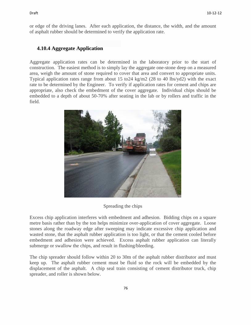
Draft 10-12-12
76
or edge of the driving lanes. After each application, the distance, the width, and the amount
of asphalt rubber should be determined to verify the application rate.
4.10.4 Aggregate Application
Aggregate application rates can be determined in the laboratory prior to the start of
construction. The easiest method is to simply lay the aggregate one-stone deep on a measured
area, weigh the amount of stone required to cover that area and convert to appropriate units.
Typical application rates range from about 15 to24 kg/m2 (28 to 40 lbs/yd2) with the exact
rate to be determined by the Engineer. To verify if application rates for cement and chips are
appropriate, also check the embedment of the cover aggregate. Individual chips should be
embedded to a depth of about 50-70% after seating in the lab or by rollers and traffic in the
field.
Spreading the chips
Excess chip application interferes with embedment and adhesion. Bidding chips on a square
metre basis rather than by the ton helps minimize over-application of cover aggregate. Loose
stones along the roadway edge after sweeping may indicate excessive chip application and
wasted stone, that the asphalt rubber application is too light, or that the cement cooled before
embedment and adhesion were achieved. Excess asphalt rubber application can literally
submerge or swallow the chips, and result in flushing/bleeding.
The chip spreader should follow within 20 to 30m of the asphalt rubber distributor and must
keep up. The asphalt rubber cement must be fluid so the rock will be embedded by the
displacement of the asphalt. A chip seal train consisting of cement distributor truck, chip
spreader, and roller is shown below.

Draft 10-12-12
77
Trucks should back into the spreader box and should not cross over any exposed asphalt
rubber membrane. This is illustrated in the photo below; the chip spreader is in the
foreground of the photo and the raised bed of the haul truck can be seen behind the spreader.
The speeds and loads of the trucks hauling the chips should be regulated to prevent damage to
the new seal. They should turn as little as possible on the new seal.
The chip spreader should be operated at a speed that will prevent the cover aggregate from
being rolled as it is being applied. The aggregate supply should be controlled to assure a
uniform distribution across the entire box. If an excess of aggregate is spread in some areas, it
should be distributed on the adjacent roadway surface or picked up. However, excess
application usually interferes with embedment and adhesion and may lead to future problems
with chip loss. Areas that do not get enough aggregate cover (about 85% of the total
membrane area is a reasonable target) should be covered with additional aggregate (normally
by hand), but problems with adhesion may occur, because by then the asphalt rubber has
cooled.
4.10.5 Rolling Asphalt Rubber Chip Seals
Pneumatic-tired rollers are normally used for rolling chip seals because the kneading action of
the rubber tires promotes embedment. The tires do not bridge across surface irregularities and
depressions, as do steel drums. Unlike RMA mixes, the tires are in contact with the cover
aggregate rather than the asphalt rubber cement, so excessive pickup is rarely a problem.
Skirts around the tires can help maintain elevated tire temperature to aid compaction. Rolling
of a chip seal is done to orient and embed the rock (get the flat sides down). Rollers should be
operated at slow speeds of about 6.4 to 9.7 km/h (4 to 6 mph) so that the rock is set in the
cement, not displaced. The number of rollers required depends on the speed of operation, as it
takes 2 to 4 passes of the roller to set the rock.
Rolling the chips
4.10.6 Sweeping

Draft 10-12-12
78
Sweeping (brooming) removes surplus aggregate from the surface of the new chip seal to
minimize flying rocks. Sweeping can usually be started within 30 minutes after chip
application. It is desirable to sweep during the cool period of the day using a rotary power
broom. The photo below shows the surface of a finished asphalt rubber chip seal after
sweeping, before application of flush coat and sand. For interlayers, no flush coat or sand is
applied.
4.10.7 Flush Coat or Fog Seal
The flush coat consists of an application of fog seal over the new asphalt rubber chip seal
followed by a sand cover. Fog Seals are applied over chip seals to help retain the cover
aggregate and provide a more uniform appearance. Fog seals are not applied over SAMI-R
because it will be covered with an overlay. Fog seals typically consist of grade CSS-1, CSS-
1h, or CQS-1 asphalt emulsion diluted with 50 percent added water. The standard application
rate over asphalt rubber chip seals is about .23 to .45 l/m2(0.05 to 0.1 gal/yd2), or as
determined by the Engineer.
4.10.8 Sand Cover
Sand cover is applied immediately after application of the fog seal to prevent pick up and
tracking of the chip seal material by vehicle tires. The sand must be clean, i.e., free of clay
fines or organic material. It is spread in a single application of about 1 to 2.2 kg/m2 (2 to 4
lbs/yd2), or at a rate determined by the Engineer.
4.10.9 Traffic Control
Some form of traffic control is required to keep the initial traffic speed on the new chip seal
below about 40 km/h (25mph). Flag persons or signs help, but the most positive means is a
pilot car. The primary purpose of the pilot car is to control the speed of the traffic through the
project. This traffic will also supply some additional pneumatic tire rolling and kneading
action.

Draft 10-12-12
79
4.11 Emissions
4.11.1 Air Quality
Concerns have been expressed regarding the effects of CRM- modified paving materials on
air quality, particularly related to HMA plant emissions and worker health and safety. CRM
consists mostly of various types of rubber and other hydrocarbons, carbon black, extender
oils, and inert fillers. Most of the chemical compounds in CRM are also present to some
extent in paving grade asphalt, although the proportions are likely to differ. CRM does not
include exotic chemicals that present any new health risks. Although a number of stack
emissions and worker exposure studies have been performed throughout the U.S. that have
not indicated any increased risk due to CRM-related emissions, concerns seem to persist.
Findings of selected Federal, state, and private studies are presented herein.
4.11.2 FHWA/USEPA Studies
In June 1993, the FHWA and the US Environmental Protection Administration (EPA) issued
a report on the “Study of The Use of Recycled Paving Material - Report to Congress” which
described an analysis of the results of seven studies to compare the relative threats/risks to
human health and the environment from conventional asphalt paving and CRM asphalt
paving. The report discussed some of the variables that influenced the health and
environmental comparisons. Conclusions indicated that the data evaluated contained no
obvious trends to indicate a significant increase or decrease in emissions attributed to the use
of CRM. The FHWA/USEPA report recommended further study of this issue. Subsequent
studies have been conducted but have not provided sufficient evidence to change the original
conclusions (references).
4.11.3 AC Plant Emissions Tests
To evaluate emissions issues, AC plant “stack tests” were performed during asphalt rubber hot
mix production in New Jersey (1994), Michigan (1994), Texas (1995), and California (1994
and 2001). The results generally indicate that emissions measured during asphalt rubber
production at HMA plants remain statistically about the same as for conventional AC and that
amounts of any hazardous components and particulates remain below mandated limits (Stout
& Carlson, 2003). That does not mean that there are no differences in raw emissions data
between production of CRM paving materials and conventional DGAC; in many cases there
are. However the actual amounts of the various compounds of interest that are measured are
typically very small for both conventional and CRM mixes, and the differences measured are
not large enough to indicate any adverse impacts.

Draft 10-12-12
80
In 2001, Caltrans investigated emissions at two AC plants in the San Francisco Bay area. The
Bay Area study was the result of severe blue smoke problems that occurred at a plant in
November 2000, which were attributed to use of CRM rather than a lack of modern emissions
controls. A partnership among the Bay Area Air Quality Management District (BA AQMD),
Caltrans, and paving industry organizations developed a plan to test AC plants producing
RMA during summer 2001. The scope of the testing program included the following:
Cal ARB Method 429 - Polyaromatic Hydrocarbons (PAH)
Cal ARB Modified Method 5 – Determination of Particulate (BTEX)
Test during production of Conventional AC and RMA in triplicate at two hot plants
Testing during normal production runs
For this study, the County of Sacramento Public Works Agency conducted stack emission
tests at two production facilities, a batch plant and a drum mix plant to compare emissions
during production of RMA and DGAC mixes. The asphalt rubber conformed to Caltrans
requirements for wet process high viscosity cement. Although results at the batch plant were
influenced by benzene exhaust from haul truck tailpipes in the truck load-out shed (other
possible sources were evaluated and ruled out), measured emissions of particulate and
specified toxic air contaminants were consistently lower than EPA AP-42 emission factors for
production of both types of mixes and both types of plants. The conclusions of the Public
Works Agency letter report on Results of Stack Emission Testing Asphalt Rubber and
Conventional Asphalt Concrete, dated Feb 5, 2002, were as follows:
Emissions from the production of RMA are not significantly different than those from
the production of conventional DGAC
Asphalt rubber is one of many types of “asphalt,” and emissions from its production
are not dissimilar to the emissions from the production of conventional asphalt
Therefore, existing production plants in the Bay Area that are permitted to produce
AC should be permitted to produce RAC.
4.11.4 Worker Health and Safety
A number of studies of worker exposure to potentially hazardous compounds in fumes from
CRM-modified asphalt paving materials have been performed. Although the compounds
were evaluated, terminology and methods may vary among these studies. The same trends are
generally repeated. Fumes generated by CRM materials at elevated temperatures compared to
conventional AC mixes often have increased concentrations of a number of compounds of
interest, but these compounds rarely exceed established permissible exposure limits.

Draft 10-12-12
81
4.11.5 National Institute for Occupational Safety and Health (NIOSH)
NIOSH, in cooperation with FHWA, has performed evaluations of possible differences in the
occupational exposures and potential health effects of CRM and conventional HMA. NIOSH
Health Hazard Evaluations were performed at seven paving projects located in Michigan,
Indiana, Florida, Arizona, Massachusetts, and California (2) from 1994 through 1997. The
purposes of the multiple studies were to assess site-specific information relative to each
project to compile results and compare the effects of exposure due to CRM and conventional
materials. The assessments included an evaluation of collected area air samples in order to
characterize the asphalt fume emission, personal breathing zone (PBZ) air samples to evaluate
worker exposures, and a medical component including questionnaires and lung function tests.
The NIOSH studies showed that the various exposure measurements evaluated for both
conventional AC and CRM asphalt paving were below the NIOSH recommended exposure
limits. Based upon the results of the individual studies, NIOSH did not draw any definitive
conclusions regarding the potential health effects of CRM asphalt compared to conventional
asphalt. These reports indicate that increases in plant emissions were related to the elevated
operating temperatures, not the presence of the CRM.
4.11.6 Industry Studies in California
A 2.5-year study was performed in Southern California to assess the effects of “Exposure of
Paving Workers to Asphalt Emissions (When Using Asphalt Rubber Mixes).” The study
began in 1989 and results were published in 1991 (Rinck, Napier and Null), before fume
exhaust ventilation and capture devices were implemented on paving equipment. The study
monitored a number of individual paving workers in direct contact with fumes during hot mix
paving operations as well as spray applications. The researchers found that emission
exposures in asphalt rubber operations did not differ statistically from those of conventional
asphalt operations. Based on results of this study, “there is no evidence to indicate that
persons who are involved in the application of asphalt rubber products are at risk from asphalt
rubber emissions.”
A worker exposure study of CRM HMA was conducted during highway construction near
Holtville, California (Caltrans Contract No. 11-172504) from November 30 through
December 1, 1994. Personal exposures were reportedly well under the existing Cal-OSHA
limits. However, measured concentrations of fumes did not vary consistently with respect to
mix temperature as has typically been noted in such studies.
4.11.7 Worker Exposure
The literature indicates that numerous studies of worker exposure to potentially hazardous

Draft 10-12-12
82
compounds in asphalt rubber fumes have been performed. Fumes generated by CRM-
modified materials at elevated temperatures often have increased concentrations of a number
of compounds of interest compared to conventional asphalt materials, but these rarely exceed
established permissible exposure limits. Thus, there is no pattern of evidence that asphalt
rubber materials present greater health hazards than conventional asphalt materials.
4.11.8 Water Quality
Water quality is another area of concern regarding the use of CRM. Southwestern
Laboratories tested leachate from stockpiles of reclaimed CRM pavement milled from IH10 in
San Antonio, Texas, to evaluate the potential for contamination of surface runoff and
groundwater.
Simulated precipitation leachates were prepared to represent the cumulative effects of acid
rainwater leaching and were analyzed for the presence of trace metals, volatile organic
compounds (VOCs) and semivolatile organic compounds. The only compound of interest that
was present at a level above the analytical detection limit was mercury, but levels detected
were below EPA limits (Crockford et al, 1995). The report concluded that levels of detectable
leachates were too low to be environmentally significant or dangerous.
4.12 Summary
This chapter presents a summary of the production and construction practices for the wet
processes used in Ontario and other places for comparison. The rubberized asphalt cements
have been produced for some time and pilot projects have been constructed for several years
in Canada.

Draft 10-12-12
83
5.0 Inspection Guide for Rubberized Asphalt Operations
5.1 Introduction
Inspection is a very important part of producing a successful project. This inspection mission
is to verify that the final field product is in conformance with the plans and specifications.
As a construction inspector, you are the vital link between the designer and the final field
product. Your knowledge of the material and equipment used to manufacture and place
Rubberized Asphalt Concrete (RAC) coupled with your expertise in the proper construction
techniques needed to ensure a high-quality, long-lasting roadway surface will determine the
performance of the final product.
Remember, the contract documents (plans, specifications, etc.) provide minimum
requirements. Any deviations below these minimum requirements will reduce the useful life
of the pavement and add additional unplanned maintenance costs.
5.1.1 Purpose
This chapter provides an overview of the basic information about RMA mix design,
manufacture, pavement surface preparation and construction techniques. The goal of the
chapter is to give you brief, yet substantial, information in a checklist format rather than
providing full descriptions of how to perform each function.
While the information presented in this chapter is geared toward the construction of HMA, the
same principles apply to the construction of conventional asphalt concrete pavements. For
Draft 10-12-12
84
more detailed information, we recommend the following publications:
Principles of Construction of Hot-Mix Asphalt Pavements, Asphalt Institute,
Manual Series No. 22
Hot-Mix Paving Handbook 2000, AASHTO, FAA, FHWA, NAPA, U.S.A.C.E.,
APWA and NACE. Available through National Asphalt Pavement Association
National Highway Institute (NHI) Hot Mix Asphalt Construction Course – FHWA
Transportation Association of Canada, Pavement Asset Design and Management
Guide 2012, Available through Transportation Association of Canada
5.1.2 Advantages of RMA
Ontario generates nearly 15 million scrap tires annually. Benefits identified with recycled
tires in RMA by other agencies include:
Ensures long-lasting, durable pavement that resists reflective cracking. Saves money. By using its superior resistance to reflective cracking, a RMA
resurfacing project can save as much as $20,000 per lane mile over AC by placing a
thinner section (50 mm (2 in) RMA vs. 102 mm (4 in) AC). Provides a highly skid-resistant surface, reduces tire noise by 50 to 80%, and resists
rutting and shoving.
Uses over 2,000 tires per lane mile in a 50 mm (2 in) thick resurfacing project, making
RMA environmentally friendly.
Provides excellent color contrast for striping and marking.
To date, the benefits of using RMA in Canada and particularly in Ontario have not been as
promising. The Ministry needs to identify and clearly document the benefits in Ontario.
5.2 Inspection of RMA Production
As an inspector, one needs to understand how RMA is produced. As discussed in the
preceding chapters of this manual, RMA is made by blending crumb rubber from scrap tires,
asphalt cement, and properly graded, sound aggregates in specified proportions in a central
mixing plant. Other additives such as high natural rubber and extender oil may be included as
appropriate. The processes for producing RMA are summarized below for the sake of
convenience.

Draft 10-12-12
85
5.2.1 Wet Process High Viscosity (Asphalt Rubber)
Blending of the crumb rubber is generally done by the "wet process" in which the crumb
rubber is blended and interacted with the hot asphalt cement prior to adding the asphalt rubber
cement to the aggregates.
Currently, the "wet process" is the major process used in states like California and Arizona. It
is also one of the primary processes being evaluated by the Province of Ontario. Two
different types of cements may be made by the wet process: high viscosity (meets ASTM
definition of asphalt rubber including minimum viscosity of 1,500 cPs, or 1.5 Pascal seconds)
and no agitation, which is often referred to as terminal blend, and has viscosity <1,500 cPs.
Viscosity is the discriminator for appropriate use. The information herein applies to high
viscosity asphalt rubber materials.
5.2.2 Wet Process no agitation (Terminal Blends)
This process, which has been used in the USA since 1995, digests the crumb rubber into the
asphalt cement at the refinery so that no agitation is required. A number of refineries in
Arizona, California, Nevada and Texas are now producing similar products, such as PG 76-
22TR+, PG 64-28TR, PG 70-22TR, MAC-15TR and MAC-TR10. An advantage of these
products is that they can be applied at much lower temperature in comparison to high-
viscosity wet process, without the need for specialized equipment. Now produced at CRM
contents greater than 15% in California, they have a variety of applications in dense- and
open/porous-graded pavements. Also, the product is homogeneous with high solubility. This
also allows it to be emulsified for slurry seal applications.
5.2.3 Dry Process
The "dry process" mixes the rubber particles with the aggregate prior to the addition of the
asphalt. This process is not used by many agencies. Caltrans has special provisions for
RUMAC, a generic dry process mix made with gap-graded aggregates, but rarely uses this
type of CRM modification. Recently constructed test sections are being monitored to evaluate
potential for wider use.
5.3 Composition of RMA, Mix Designs and Certification
5.3.1 Aggregates

Draft 10-12-12
86
In Ontario, two gradations are used in RMA mixes. Gap-graded is used when the field
blended process is employed while a dense-graded aggregate is used when the terminal blends
are employed. Aggregate properties for RMA must meet either the requirements of
Superpave 12.5 FC 2 or Superpave 9.5.
5.3.2 Rubberized Asphalt Cements
CRM added to the RMA shall meet the gradation requirements specified in Table R3 of
Appendix C and determined according to ASTM D5644. Wet-terminal blend RMA is
produced as a Type III Asphalt Rubber Cement according to ASTM D6114. CR dosage by
mass of wet-terminal blend RMA shall be 10% to 15%. Wet-field blend RMA (after reaction)
shall meet the requirements found in Table R4. CR dosage by mass of wet-field blend RMA
shall be 18 to 20%. For the production of the RAC, parameters such as CR gradation, mixing
method and equipment, dosage, reaction time, mixing temperature, storage conditions and
need for agitation, blending location (project site vs. asphalt supplier’s terminal) shall be
determined by the Contractor.
When the RMA supplier specifies a CR gradation with additional restrictions, the CR shall
also meet the RMA supplier’s gradation requirements. The CR material, PGAC and any anti-
stripping additives required shall be compatible to ensure a good dissolution and reaction
time. RMA produced shall be a homogenous mixture of CR and asphalt cement.
5.3.3 Mix Design and Certifications
A mix design is provided by the Contractor and reviewed by the Agency. The Contractor
certifies that the mix provided corresponds to the submitted mix design. A mix design should
include:
Combined aggregate gradation
Cement content
CRM content (scrap tire and high natural)
CRM gradation (scrap tire and high natural)
Maximum density – Rice
Air voids at laboratory density
Voids in mineral aggregate (VMA)
The mix design process currently used in Ontario is summarized in Appendix D. It makes use of
the Superpave mix design process
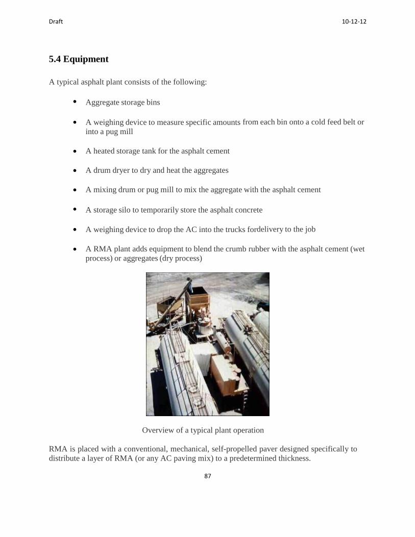
Draft 10-12-12
87
5.4 Equipment
A typical asphalt plant consists of the following:
Aggregate storage bins
A weighing device to measure specific amounts from each bin onto a cold feed belt or
into a pug mill
A heated storage tank for the asphalt cement
A drum dryer to dry and heat the aggregates
A mixing drum or pug mill to mix the aggregate with the asphalt cement
A storage silo to temporarily store the asphalt concrete
A weighing device to drop the AC into the trucks fordelivery to the job
A RMA plant adds equipment to blend the crumb rubber with the asphalt cement (wet
process) or aggregates (dry process)
Overview of a typical plant operation
RMA is placed with a conventional, mechanical, self-propelled paver designed specifically to
distribute a layer of RMA (or any AC paving mix) to a predetermined thickness.

Draft 10-12-12
88
Compaction is done with self-propelled, vibrating steel wheel rollers. Rubber tired rollers are
not permitted due to potential for pick up. Vibratory mode is used for the break down
coverages, and static mode for intermediate and finish rolling.
5.5 Surface Preparation
The existing pavement to be resurfaced shall be clean with all cracks over 6 mm (1/4 in) filled
(do not overfill) and all badly deteriorated sections removed and replaced. Longitudinal and
transverse joins shall be milled. An approved tack coat (preferably paving grade asphalt)
shall be applied evenly at the specified rate over the entire surface to be paved.
5.6 Inspection at the Plant
Inspection at the plant should take place at various locations. This section provides checklists
for items to be checked.
5.6.1 Plant Inspection Is Critical to Success of Every RMA Project
Problems observed at the plant can be corrected immediately to ensure that the material
delivered to the site conforms to the specifications. Important items to watch for at the plant:
Verify that the scales have been certified for accuracy.
Check aggregate bins for properly sized material in each bin.
Check aggregates off of the cold feed belt for proper gradation.
Monitor the proportioning devices to verify that the proper amount of crumb rubber is
added to the asphalt cement and to ensure that the proper amount of asphalt rubber
cement is added to the aggregates.
Check the viscosity of the asphalt rubber cement to make sure that it meets
requirements and that the crumb rubber is thoroughly blended and interacted with the
asphalt cement.
Take samples of the crumb rubber, aggregates, asphalt cement, asphalt rubber cement,
and RMA mix for possible laboratory testing. Test as needed.
Check the temperature of the RMA in the trucks.

Draft 10-12-12
89
Haul trucks should be covered (tarped) to maintain RMA mix temperature.
Maintain an accurate log of test samples, aggregate gradations, CRM quantities,
viscosity measurements and corresponding temperatures of the asphalt rubber cement.
5.7 Inspection at the Site
At the construction site, you have the opportunity to help ensure that the materials and the lay
down procedures are consistent with those that will result in a high-quality product. By
working with the Contractor's foreman, you help resolve potential problems and correct
irregularities.
It is extremely important, however, to remember that you should not direct the work; that is the
Contractor's responsibility.
5.7.1 Prior to Paving
For overlays, check existing pavement condition and the following:
Are cracks over 6mm (1/4 in) filled? Is application of sealant too heavy?
Are the badly deteriorated areas repaired?
Are the joints milled?
Is the surface clean?
Has the tack coat been properly applied?
In addition, one needs to check the following:
Ambient temperature and the temperature of the pavement to be resurfaced.
Specifications require minimum air and pavement temperatures of 13 ºC and rising.
At minimum temperatures, little time is available for compaction.
Ensure that the paver and the rollers are the proper type and that they are in good
working order.
Verify that the specified numbers of rollers are on the job and that there is a trained
operator available for each.
Remember, compaction is the key to long-lasting pavement and compaction depends on the temperature of the mat.
There must be a sufficient number of breakdown rollers to cover the width of each paver pass
Draft 10-12-12
90
immediately behind the paver. In California, the Greenbook requires higher temperatures for mix delivery and compaction than Caltrans specifies. Breakdown compaction should start before mix temperature drops below 143ºC (Greenbook) or 138ºC (Caltrans). To meet compaction requirements, it is typically necessary to achieve at least 95% of the required compaction during breakdown rolling, before the mat temperature drops below 127ºC.
It is necessary to verify that the method of delivery of the RMA is appropriate for the job and weather conditions (end dumps vs. bottom dumps). When weather is marginally cool, windrows are not recommended.
5.7.2 During Paving
The following items need to be checked during the paving operations:
Collect load tickets on a regular basis and calculate the yield to ensure that the proper
thickness is being placed.
Physically verify mat thickness at spot locations.
Verify that the paver is operating at a speed that is consistent with the delivery of the
mix. Pavers should not have to wait between loads of mix and loads of mix should
not have to wait to unload.
Verify that the screed height is not being adjusted unnecessarily
Are the trucks carefully backing up to the paver?
Is the paver pushing the trucks?
Does the rate of loading the RMA into the hopper result in a full hopper
without spilling over the sides?
Is the roller drive wheel forward?
Are the roller’s wheels kept wet to avoid picking up the RMA mix and are the
scraper pads effective?
Is the roller operator reversing directions on existing or newly cooled pavement?
Is the roller operator rolling the joints properly and rolling the mat from the low side
toward the high side?
Visually inspect the RMA as the trucks dump it into the hopper by checking the following:

Draft 10-12-12
91
Is the RMA mixture smoking? (too hot)
Is the RMA mixture stiff? (too cool)
Is the RMA mixture shiny or slumped? (Excessive cement - maybe. RAC mixes may
look rich even at correct asphalt rubber content, so sample and test.)
Is the RMA mixture segregated? (Improper mixing or handling – maybe. Gap- and
open-graded mixes can look segregated due to limited fines, so sample and test
aggregate gradation and cement content.)
Verify that the breakdown roller(s) follow immediately behind the paver and that the
breakdown rolling is completed before the mat reaches 127ºC.
5.7.3 After Paving
The following items need to be checked after paving is complete:
Check the compacted pavement surface for roller marks, scuffing, irregularities,
smoothness, etc.
Verify relative compaction by nuclear gauge or lab testing of pavement cores.
Check the longitudinal and transverse joints for evenness, texture, and ride.
Keep an accurate record of the tons placed and the area that was paved. Note any
rejected loads or unusual occurrences.
5.8 Summary
RMA is a proven product that will stretch your agency's roadway maintenance funds and help reduce the stockpiles of scrap tires in California. When used in appropriate situations and constructed properly, RMA will produce a safe, high-quality, durable, quiet road that is more cost effective than conventional asphalt concrete. However, quality construction is a must!
As the eyes and ears of the agency you represent, you are charged with a great responsibility. Each project has been designed in accordance with accepted criteria using specifications that are, in reality, minimum requirements for the quality of the materials and the workmanship. Your job is to verify that the final field product conforms to the plans and specifications. It is an important job. It deserves your full attention.

Draft 10-12-12
92
6.0 Summary of Key Points
This final chapter presents a summary of the key points raised in this manual. As stated in the manual, the Ministry of Transportation of Ontario has been placing projects throughout the province using difference rubberized asphalt processes. They have made use of asphalt rubber similar to that used in California and Arizona in gap-graded mixes. This product contains at least 18 % crumb rubber modifiers and requires a special field blending unit to react the rubber. The terminal blends, which often contain less crumb rubber contents and are blended at the refinery, is also used in Ontario primarily in dense graded mixes. These are products similar to those used in the United States.
The manual contains important information on the following:
Application and use. In Chapter 2, the manual discusses the types of applications and
when and where they should or could be used.
Design and specification guide. In Chapter 3, the manual discusses how the products
should be designed and specified including the cements and the mixes. Structural
design consideration are mentioned but not included in detail.
Production and construction. Chapter 4 presents information on the production of the
cements as well as construction of both hot mix and spray applications.
Inspection. Chapter 5 presents checklists on things to look for during inspection. You
get what you inspect so it is important to make sure inspectors are collecting the
correct information.
Ontario has placed a number of pilot projects in recent years. If the guides suggested in this
manual are followed, one can expect that the performance of the rubberized asphalt placed will
performed well.
Draft 10-12-12
93
7.0. References
Anthony, A.M. and C.F Berthelot. 2008. Preliminary Findings from Saskatchewan’s
Asphalt Rubber Project, Proceedings, Canadian Technical Asphalt Association, 53, 281 –
311
American Association of State Highway and Transportation (AASHTO). 2010. Standard
Specifications for Transportation Materials and Methods for Sampling and Testing. 30th
ed. Washington: AASHTO.
American Society for Testing Materials (ASTM). 2001. ASTM D92 Standard Test
Method for Flash and Fire Points by Cleveland Open Cup. West Conshohoken, PA:
ASTM.
American Society for Testing Materials (ASTM). 2004. ASTM D2872 Standard Test
Method for Effect of Heat and Air on a Moving Film of Asphalt (Rolling Thin Film Oven
Test). West Conshohoken, PA: ASTM.
American Society for Testing Materials (ASTM). 2006a. ASTM D4402 Standard Test
Method for Viscosity Determination of Asphalt at Elevated Temperatures Using a
Rotational Viscometer. West Conshohoken, PA: ASTM.
American Society for Testing Materials (ASTM). 2006b. ASTM D5 - 06e1 Standard Test
Method for Penetration of Bituminous Mixes. West Conshohoken, PA: ASTM.
American Society for Testing Materials (ASTM). 2009a. ASTM D5329 - 09 Standard
Test Methods for Sealants and Fillers, Hot Applied, for Joints and Cracks in Asphaltic
and Portland Cement Concrete Pavements. West Conshohoken, PA: ASTM.
American Society for Testing Materials (ASTM). 2009b. ASTM D36 / D36M - 09
Standard Test Method for Softening Point of Bitumen (Ring and Ball Apparatus). West
Conshohoken, PA: ASTM.
Asphalt Institute. (AI). 2008. Terminal Blended Rubberized Asphalt Goes Mainstream –
Now PG Graded, Asphalt The Magazine of the Asphalt Institute, November, Lexington,
KY: AI.
Asphalt Institute. (AI). 2009. MS-19 Basic Asphalt Emulsion Manual, 4th ed. Lexington,
KY: AI.
Aurilio, V. 1993. Experimental Hot Mix Pavement with Scrap Tire Rubber At
Thamesville, Ontario – Report #2, Proceedings, Canadian Technical Asphalt Association,
38, 51 – 76
Draft 10-12-12
94
California Department of Resources Recycling and Recovery. 2010. Rubberized asphalt
concrete technology transfer series. Retrieved from
http://www.calrecycle.ca.gov/Tires/RAC/TechAssist.htm
California Department of Transportation. 2008. Highway Design Manual Chapter 630 on
Flexible Pavement. Retrieved from
http://www.dot.ca.gov/hq/oppd/hdm/pdf/english/chp0630.pdf
Carrick, J.J., J.K. Davidson, V. Aurilio, and J. Emery.1995. Use of Asphalt Rubber,
Proceedings, Canadian Technical Asphalt Association, 40, 57 – 77
Cheng, D., R.G. Hicks, L. Lerose. Using Warm Mix Technology to Improve Applications
of Asphalt Rubber in California. The 2nd International Warm Mix Conference, St. Louis,
Missouri, October 2011.
Cheng, D., R.G. Hicks, T. Teesdale. Assessment of Warm Mix Technologies for Use
with Asphalt Rubber Paving Applications. Paper presented at the 90th annual meeting in
Washington D.C., January 2011.
Emery, J. 1994. Evaluation of Rubber-Modified Asphalt Demonstration Projects,
Proceedings, Canadian Technical Asphalt Association, 39, 337 – 361
Federal Highway Administration (FHWA). 2008. Warm-Mix Asphalt: European
Practice, FHWA-PL-08-007. Washington: U.S. Department of Transportation.
Hicks, R.G., D. Cheng, and T. Teesdale. 2011. Assessment of Warm Mix Technologies
for Use with Asphalt Rubber Paving Applications, presentation Transportation Research
Board meeting, Washington DC
Johnson, R., J. Sproule, and A. Juristovski.1995.The Full Scale Evaluation of Rubberized
Asphalt Concrete in British Columbia, Proceedings, Canadian Technical Asphalt
Association, 40, 38 – 56
Johnston, A., M. Oliver, and B. Pulles. 2005. A Full Scale Demonstration Project to
Evaluate Asphalt Rubber Pavement – Highway 6, British Columbia, Proceedings,
Canadian Technical Asphalt Association, 50, 315 – 335
Juhasz, M. and C. McMillan. 2007.Alberta Infrastructure and Transportation’s
Experience with Asphalt Rubber, Proceedings, Canadian Technical Asphalt Association,
52, 185 – 214
Kennepohl, G., and K. Davidson. 1992. Introduction of Stone Mastic Asphalts (SMA) in
Ontario. Journal, Association of Asphalt Paving Technologists.517-534.
Draft 10-12-12
95
Lawrence, C.E., B.J. Killackey, and D.F. Lynch. 1991. Experimental Hot Mix Pavement
with Scrap Tire Rubber at Thamesville, Ontario, Proceedings, Canadian Technical
Asphalt Association, 36, 61 – 86
Leung, F., S. Tighe, G. MacDonald and S. Penton, 2006. Development of Tools to
Evaluate Quiet Pavements in the Laboratory and Field, Transportation Association of
Canada Conference Proceedings, Prince Edward Island, September
MacLeod D.R. 2004. Integration of Pavement Management into the Strategic Plan for
the Reconstruction of the Alaska (Alcan) Highway. Proceedings. 6th International
Conference on Managing Pavements. Brisbane, Australia.
MacLeod, D., A. Johnston, S. Ho, and L. Zanzotto. (2007). “Effectiveness of Crumb
Rubber Materials as Modifiers in Paving Asphalt”, Proceedings, Canadian Technical
Asphalt Association, 52, 1 – 20
McMillan, C., Kwan, A., Donovan, H., Enslen, P., & Horton, P. 2003. Current asphalt
rubber developments in Alberta. Retrieved from http://www.tac-
atc.ca/english/resourcecentre/readingroom/conference/conf2003/pdfs/mcmillan.pdf
Minnesota Department of Transportation (MnDOT), 2006. Minnesota Seal Coat Manual
2006. Maplewood, MN: MnDOT.
National Asphalt Pavement Association. 2012. Warm Asphalt. National Asphalt
Pavement Association. Lanham, MD. Retrieved from http://www.warmmixasphalt.com/
Ontario Hot Mix Producers Association. 1999. ABC’s of PGAC. Retrieved from Ontario
Hot Mix Producers website http://www.ohmpa.org/lib/db2file.asp?fileid=189
Rozeveld S, E Shin, A Bhurke, L France, L Drzal. Network Morphology of Straight
and Polymer Modified Asphalt Cements. Microscopy Research and Technique, Vol. 38,
pp. 529–543, 1997.
Sacramento County Department of Environmental Review and Assessment & Bollard
and Brennan, Inc. 1999. Effectiveness of rubberized asphalt in reducing traffic noise.
Retrieved from http://www.asphaltrubber.org/library/sacramento_noise_study/index.html
Scott, J.L.M. 1984. Five Years with Rubber Asphalt Seals, Proceedings, Canadian
Technical Asphalt Association, 29 191 – 201
Scott, J.L.M. 1979. Use of Rubber Asphalt Binder with Graded Aggregate for Seal Coats,
Proceedings, Canadian Technical Asphalt Association, 24, 40 – 76
Tabib, S., P. Marks, M. Ahmed, and K. Tam. 2009. Ontario’s Experience with Rubber
Modified Hot Mix Asphalt, Proceedings, Canadian Technical Asphalt Association, 54,
173 – 190

Draft 10-12-12
96
Transportation Association of Canada. 2012. Draft Pavement Asset Design and
Management Guide. Prepared under contract University of Waterloo.
Washington State Department of Transportation, 2012. Pavement Design Manual.
Retrieved from Washington State Department of Transportation.
http://training.ce.washington.edu/wsdot/Modules/03_materials/03-
2_body.htm#gradation_terminology
Xu H, A McIntyre, T Adhikari, S Hesp, P Marks, S Tabib. Quality and durability of
warm rubberized asphalt cement in Ontario. Transportation Research Record: Journal of
the Transportation Research Board, 2013 (Submitted for Presentation and Publication).

Draft 10-12-12
97
8.0 Appendices
Appendix A. Glossary
A.1 Types of Rubberized Asphalt
Asphalt rubber binder (ARB) – is used in various types of flexible pavement construction
including surface treatments and hot mixes. According to the ASTM definition (ASTM D
8, Vol. 4.03, “Road and Paving Materials” of the Annual Book of ASTM Standards 2006)
asphalt rubber is “a blend of asphalt cement, reclaimed tire rubber, and certain additives in
which the rubber component is at least 15 percent by weight of the total blend and has
reacted in the hot asphalt cement sufficiently to cause swelling of the rubber particles.” By
definition, asphalt rubber binder is prepared using the “wet process.” The Ontario
specifications for ARB physical properties fall within the ranges listed in ASTM D 6114,
“Standard Specification for Asphalt Rubber Binder,” also located in Vol. 4.03. Recycled
tire rubber is used for the reclaimed rubber and is currently referred to as crumb rubber
modifier (CRM). The asphalt cement and CRM are mixed and interacted at elevated
temperatures and under high agitation to promote the physical interaction of the asphalt
cement and CRM constituents. During ARB production and storage, agitation is required to
keep the CRM particles suspended in the blend. Various petroleum distillates or extender
oil may be added to reduce viscosity, facilitate spray applications, and promote workability
(See Wet Process).
Dry process – any method that includes scrap tire CRM as a substitute for 1 to 3% of the
aggregate in an asphalt concrete paving mixture, not as part of the asphalt binder. The CRM
acts as a rubber aggregate in the paving mixture. This method applies only to production of
CRM-modified AC mixtures. A variety of CRM gradations have been used, ranging from
coarse rubber (1/4 in. to plus No. 8 (6.3 to 2.36 mm) sieve sizes) to “Ultrafine” minus No.
80 (180 µm) sized CRM. Caltrans has a special provision for RUMAC which includes an
intermediate CRM gradation specification. Care must be taken during the mix design to
make appropriate adjustments for the low specific gravity of the CRM compared to the
aggregate material to assure proper volumetric analysis. Several methods have been
established for feeding the CRM dry with the aggregate into hot plant mixing units before
the mixture is charged with asphalt cement. Although there may be some limited interaction
of the CRM with the asphalt cement during mixing in the AC plant, silo storage, hauling,
placement and compaction, the asphalt cement is not considered to be modified in the dry
process.
Semi Dry Process - The semi-dry/semi-wet or moist process lies somewhere between the
wet and dry processes. Very fine rubber crumbs are added to the mixer just prior to the
addition of asphalt cement. A longer mixing time is required than for normal HMA to
allow for some reaction between the crumb rubber and AC, resulting in partially modified
asphalt cement.

Draft 10-12-12
98
Rubberized asphalt - asphalt cement modified with CRM that may include less than 15 %
CRM by mass and thus may not comply with the ASTM definition of asphalt rubber . In
the past, terminal blends (wet process, no agitation CRM-modified asphalt binders
including Modified Binder (MB) materials) have typically fallen in this category. In
California, the terminal blend suppliers now provide products that are greater than the 15
% CRM that has traditionally been used.
Terminal blend – See Wet Process- No Agitation or Rubberized asphalt
Wet Process - the method of modifying asphalt binder with CRM produced from scrap tire
rubber and other components as required before incorporating the binder into the asphalt
paving materials. Caltrans requires the use of extender oil and addition of high natural
CRM. The wet process requires thorough mixing of the crumb CRM in hot asphalt cement
(375ºF to 435ºF, 190ºC to 224ºC) and holding the resulting blend at elevated temperatures
(375ºF to 425ºF, 190ºC to 218ºC) for a designated minimum period of time (typically 45
minutes) to permit an interaction between the CRM and asphalt. Caltrans specification
requirements include an operating range for rotational viscosity and cone penetration, and
minimum values of softening point and resilience.
The wet process can be used to produce a wide variety of CRM modified binders that have
corresponding respective ranges of physical properties. However the most important
distinctions among the various blends seem to be related to rotational viscosity of the
resulting CRM-asphalt cement blend at high temperature (threshold is 1,500 centipoises
(cPs) or 1.5 Pa/sec at 375ºF (190ºC) depending on governing specification) and whether or
not the blend requires constant agitation to maintain a relatively uniform distribution of
rubber particles. Viscosity is strongly related to the size of the scrap tire CRM particles
and tire rubber content of the CRM-modified blend. CRM gradations used in the wet
process are typically minus No. 10 (2 mm) sieve size or finer. CRM-modified binders with
viscosities = 1,500 cPs at 375ºF (190ºC) should be assumed to require agitation.
Wet Process-No Agitation - A form of the wet process where CRM is blended with
hot asphalt cement at the refinery or at an asphalt storage and distribution terminal and
transported to the HMA mixing plant or job site for use. This type of rubberized
asphalt (which includes Rubber Modified Binder( RMB)) does not require subsequent
agitation to keep the CRM particles evenly dispersed in the modified binder. The term
“terminal blend” is often used to describe such materials, although they may also be
produced in the field.
The preferred description for this type of binder is “wet process-no agitation.” Such binders are typically modified with CRM particles finer than the No. 50 (300 μm) sieve size that can be digested (broken down and melted in) relatively quickly and/or can be kept dispersed by normal circulation within the storage tank rather than by agitation by special augers or paddles. Polymers and other additives may also be included. In the past, rubber contents for such blends have generally been = 10% by mass of asphalt or total binder (which does not satisfy the ASTM D 8 definition of asphalt rubber), but current reports indicate some California products now include 15% or more CRM. Although such
Draft 10-12-12
99
binders may develop a considerable level of rubber modification, rotational viscosity values rarely approach the minimum threshold of 1500 (cPs) or 1.5 Pa/s at 375ºF (190ºC) that is necessary to significantly increase binder contents above those of conventional HMA mixes without excessive drain-down. One advantage is these products can be applied at much lower temperature without the need for specialized equipment.
Wet Process-High Viscosity - CRM-modified binders that maintain or exceed the
minimum rotational viscosity threshold of 1500 cPs at 375ºF (190ºC) over the interaction
period should be described as “wet process–high viscosity” binders to distinguish their
physical properties from those of wet process-no agitation materials. These binders require
agitation to keep the CRM particles evenly distributed. They may be manufactured in large
stationary tanks or in mobile blending units that pump into agitated stationary or mobile
storage tanks. Wet process-high viscosity binders include asphalt rubber materials that
meet the requirements of ASTM D6114. Wet process-high viscosity binders typically
require at least 15% scrap tire rubber to achieve the threshold viscosity. Caltrans requires a
minimum total CRM content of 18%.
A.2 Types of Rubber
Crumb rubber modifier (CRM) – general term for scrap tire rubber that is reduced in size for
use as a modifier in asphalt paving materials. Several types are defined herein. A variety of
processes and equipment may be used to accomplish the size reduction as follows:
Ground crumb rubber modifier – irregularly shaped, torn scrap rubber particles with
a large surface area, generally produced by a cracker mill.
High natural rubber (Hi Nat) – scrap rubber product that includes 40-48 % natural rubber
or isoprene and a minimum of 50% rubber hydrocarbon according to Caltrans
requirements. Sources of high natural rubber include scrap tire rubber from some types of
heavy truck tires, but are not limited to scrap tires. Other sources of high natural rubber
include scrap from tennis balls and mat rubber.
Buffing waste – high quality scrap tire rubber that is a byproduct from the conditioning
of tire carcasses in preparation for re-treading. Buffings contain essentially no metal or
fiber.
Tread rubber – scrap tire rubber that consists primarily of tread rubber with less
than approximately 5% sidewall rubber.
Tread peel – pieces of scrap tire tread rubber that are also a byproduct of tire re-treading
operations that contain little if any tire cord.
Whole tire rubber – scrap tire rubber that includes tread and sidewalls in proportions that
approximate the respective weights in an average tire. Devulcanized rubber – rubber that has been subjected to treatment by heat, pressure, or
the addition of softening agents after grinding, to alter physical and chemical properties of

Draft 10-12-12
100
the recycled material.
Automobile tires – tires with an outside diameter less than 26 in. (660 mm) used on
automobiles, pickups, and light trucks.
Recycled tire rubber – rubber obtained by processing used automobile, truck, or bus tires
(essentially highway or “over the road” tires). Chemical requirements for scrap tire rubber
are intended to eliminate unsuitable sources of scrap tire rubber such as solid tires; tires
from forklifts, aircraft, and earthmoving equipment; and other non-automotive tires that do
not provide the appropriate components for asphalt rubber interaction. Non-tire rubber
sources may be used only to provide High Natural Rubber to supplement the recycled tire
rubber.
Truck tires – tires with an outside diameter greater than 26 in. (660 mm) and less than 60 in.
(1520 mm), used on commercial trucks and buses.
Vulcanized rubber – crude or synthetic rubber that has been subjected to treatment by
chemicals, heat and/or pressure to improve strength, stability, durability, etc. Tire rubber
is vulcanized.
A.3 CRM Preparation Methods
Ambient grinding - method of processing where scrap tire rubber is ground or processed at
or above ordinary room temperature. Ambient processing is typically required to provide
irregularly shaped, torn particles with relatively large surface areas to promote interaction
with the asphalt cement.
Cryogenic grinding – process that uses liquid nitrogen to freeze the scrap tire rubber until it
becomes brittle and then uses a hammer mill to shatter the frozen rubber into smooth
particles with relatively small surface area. This method is used to reduce particle size prior
to grinding at ambient temperatures.
Granulation – produces cubical, uniformly shaped, cut crumb rubber particles with a
low surface area.
Shredding – process that reduces scrap tires to pieces 6 in.
2 (0.023 m
2) and smaller prior to
granulation or ambient grinding.
A.4 CRM Processing Equipment
Cracker mill – apparatus typically used for ambient grinding, that tears apart scrap tire
rubber by passing the material between rotating corrugated steel drums, reducing the size of
the rubber to a crumb particle generally No. 4 to No. 40 (4.75 mm to 425 mm) sieve size.
Granulator – apparatus that shears apart the scrap tire rubber, cutting the rubber with
revolving steel plates that pass at close tolerance, reducing the rubber to cubicle particles

Draft 10-12-12
101
generally 3/8 in. to No. 10 sieve (9.5 mm to 2.0 mm) in size.
Micro-mill – process that further grinds crumb rubber particles to sizes below the No. 40
(425 mm) sieve size.
A.5 Mix Types
Rubberized asphalt concrete (RAC) – material produced for hot mix applications by
mixing asphalt rubber or rubberized asphalt binder with graded aggregate. RMA may be
dense-gap-, or open-graded.
Dense-graded – refers to a continuously graded aggregate blend typically
used to make hot-mix asphalt concrete (HMA) pavements with conventional
or modified binders.
Gap-graded – aggregate that is not continuously graded for all size fractions, but
is typically missing or low on some of the finer size fractions (minus No. 8 (2.36
mm) or finer). Such gradations typically plot below the maximum density line on
a 0.45 power gradation chart. Gap-grading is used to promote stone-to-stone
contact in HMA and is similar to the gradations used in stone matrix asphalt
(SMA), but with relatively low percentages passing the No. 200 (75 µm) sieve
size. This type of gradation is most frequently used to make rubberized asphalt
concrete gap-graded (RAC-G) paving mixtures.
Open-graded – aggregate gradation that is intended to be free draining and
consists mostly of 2 or 3 nominal sizes of aggregate particles with few fines and
0 to 4% by mass passing the No. 200 (0.075 mm) sieve. Open-grading is used in
hot-mix applications to provide relatively thin surface or wearing courses with
good frictional characteristics that quickly drain surface water to reduce
hydroplaning, splash and spray.
Warm mix asphalt rubber mixes. Warm mix additives have been used in
California with open- and gap-graded asphalt rubber mixes and terminal blends
to extend the construction season, improve cool weather compaction and extend
the haul distance.
RUMAC – This is a generic type of dry process RMA mixture that has taken the place of
proprietary dry process systems such as PlusRide. This type of product is still used in
some states, like Alaska.
A.5 Other Mix Ingredients Other in
Diluent – a lighter petroleum product (typically kerosene or similar product with solvent-like characteristics) added to asphalt rubber binder just before the binder is sprayed on the pavement surface for chip seal applications. The diluent thins the binder to promote fanning and uniform spray application, and then evaporates over time without causing major changes to the asphalt

Draft 10-12-12
102
rubber properties. Diluent is not used in ARB to make HMA, and is not recommended for use in interlayers that will be overlaid with HMA in less than 90 days due to on-going evaporation of volatile components.
Extender oil – aromatic oil used to promote the reaction of the asphalt cement and the
crumb rubber modifier.
Flush coat – application of diluted emulsified asphalt onto a pavement surface to extend
pavement life that may also be used to prevent rock loss in chip seals or raveling in HMA.
A.6 Reactions between Rubber and Asphalt
Interaction – the physical exchange between asphalt cement and CRM when blended
together at elevated temperatures, which includes swelling of the rubber particles and
development of specified physical properties of the asphalt and CRM blend to meet
requirements. Although often referred to as reaction, interaction is not a chemical reaction
but rather a physical interaction in which the CRM absorbs aromatic oils and light
fractions (small volatile or active molecules) from the asphalt cement, and releases some
of the similar oils used in rubber compounding into the asphalt cement. The interaction
may be more appropriately defined as polymer swell.
Reaction – commonly used term for the interaction between asphalt cement and crumb rubber
modifier when blended together at elevated temperatures (see Interaction).
A.7 Interlayers
Stress-absorbing membrane (SAM) – a chip seal that consists of a hot asphalt rubber
binder sprayed on the existing pavement surface followed immediately by an application of a
uniform sized cover aggregate which is then rolled and embedded into the binder membrane.
Its nominal thickness generally ranges between 3/8 and 1/2-in. (9 and 12 mm) depending on
the size of the cover aggregate. A SAM is a surface treatment that is used primarily to restore
surface frictional characteristics, seal cracks and provide a waterproof membrane to
minimize the intrusion of surface water into the pavement structure. SAMs are used for
pavement preservation, maintenance, and limited repairs. Asphalt rubber SAMs minimize
reflective cracking from an underlying distressed asphalt or rigid pavement, and can help
maintain serviceability of the pavement pending rehabilitation or reconstruction operations. Stress-absorbing membrane interlayer (SAMI) - originally defined as a spray application of
asphalt rubber binder and cover aggregate. However, interlayers now may include asphalt rubber
chip seal (SAMI-R), fabric (SAMI-F), or fine unbound aggregate.
Stress-absorbing membrane interlayer-Rubber (SAMI-R) – SAMI-R is an asphalt
rubber SAM that is overlaid with an asphalt paving mix that may or may not include CRM.
The SAMI-R delays the propagation of the cracks (reflective cracking) through the new
overlay.

Draft 10-12-12
103
A.8 Aggregates for Asphalt Concrete
General description. Most aggregates can be used in rubberized asphalt concrete mixes or chip
seals. They include the following:
Classification of Rock • Sedimentary
• Igneous
• Metamorphic Aggregate Sources
• Natural aggregates - gravel, sand
• Processed aggregates - crushed aggregate • Synthetic aggregates - blast furnace slag
Lightweight aggregate – porous aggregate with very low density such as expanded
shale, which is typically manufactured. It has been used in chip seals to reduce
windshield damage.
Important aggregate properties. Some of the important properties are given below:
Maximum Particle Size and Gradation
• Specified for each asphalt concrete paving mix
• Coarse aggregate - retained on the No. 4 sieve • Fine aggregate - passes the No. 4 sieve • Mineral filler/dust - passes the No. 200 sieve
Specific Gravity
• Aggregates of low specific gravity cover a larger volume per ton and, therefore, require a higher percentage of asphalt cement.
• Aggregates of high specific gravity cover a lower volume per ton and, therefore, require a lower percentage of asphalt cement.
Cleanliness
• Free of unsuitable material • Toughness • Abrasion resistant
Particle Shape
• Crushed particles interlock to provide strength. • Fine, rounded particles provide workability but act as ball bearings in the
mix so content should be limited. Many agencies limit such materials to a maximum of 15% of the total aggregate to minimize adverse effects on aggregate interlock and VMA.
Surface Texture
• Asphalt tends to strip from smooth surfaces.

Draft 10-12-12
104
Absorptive Capacity
• Ability to absorb asphalt influences the total amount of asphalt
required. High absorption increases binder content.
Affinity to Asphalt • Ability of the aggregate to bond with the asphalt binder • This affects moisture sensitivity.
A.9 Asphalt
Asphalts are materials that consist of black cementitious material made up largely of
hydrocarbons and are a visco-elastic plastic material - brittle and hard when cold; soft and viscous
when hot. Classes of asphalts include:
• Asphalt cement (paving grade asphalt)
• Liquid asphalt (mixed with cutbacks) - not used in RAC
• Emulsified asphalt (mixed with water) - not used in RAC Important physical properties include:
Durability
Adhesion
Temperature susceptibility - CRM modification reduces temperature
susceptibility
Aging and hardening
Viscosity – is the property of resistance to flow (shearing force) in a fluid or
semi-fluid. Thick stiff fluids such as asphalt rubber have high viscosity;
water has low viscosity. Viscosity is specified as a measure of field quality
control for asphalt rubber production and its use in RMA mixtures.
A.10 Asphalt Binder Tests
The following tests are used for asphalt rubber binders, but not for testing Performance
Graded (PG) asphalt:
Viscosity - ability to flow, consistency - temperature dependent
Penetration - hardness value, also measure of consistency at single temperature
Flashpoint - temperature at which a sample "flashes" i.e. bursts into flame
Thin Film Test/Rolling Thin Film Test - aging methods
Ductility – discrete CRM particles affect test results, typically exhibits early

Draft 10-12-12
105
fracture.
Specific Gravity – used in volumetric mix design calculations, and for
metering during mix production
A.11 Mix Design Methods
Mix design methods used for rubberized asphalt mixes are to determine the optimum binder
content. The methods used have included:
Marshall Mix Design Method Hot mix asphalt paving mixes, one-inch maximum size aggregate (for 4-inch
molds) Determines optimum asphalt cement content for a particular blend of aggregates.
Principal features are: 1) a density/void analysis and 2) a Marshall stability/ flow
test. HVEEM Mix Design Method (used in California)
Hot mix paving, one-inch maximum size aggregate
Principal features are: Centrifuge Kerosene Equivalent
Hveem Stability test
Swell test (permeability)
Air voids
Bleeding/flushing.
Superpave Mix Design Method (used in Ontario) –See Appendix D
A.12 Mix Design Characteristics
Mix design of asphalt and rubberized asphalt paving mixes is a tradeoff between high binder content to enhance long term durability and performance, and sufficient in-place void space to avoid rutting, instability, flushing and bleeding.
Air voids provide spaces for the movement of the asphalt cement or asphalt rubber binder within the compacted mix.
High air voids indicate relatively low density and increased permeability of the compacted mix. The maximum design target is 6% air voids, for special high volume and/or hot climate conditions.
Low density typically results in raveling and/or stripping, increased susceptibility to aging, fatigue, and environmental damage, and related reduced service life.
Low air voids indicate relatively high density and increased tendency for
asphalt flushing, and mixture rutting and shoving. The minimum design target
is 3% air voids.
High density also enhances resistance to fatigue and environmental damage,
long term performance and durability, as long as in-place air voids are
sufficient to prevent bleeding or instability.
Draft 10-12-12
106
Voids in Mineral Aggregate (VMA) • Total voids excluding those permeable to water and asphalt. VMA is a
function of aggregate gradation, particle shape and texture. • Proper VMA provides sufficient space for binder, which results in durable asphalt
film thickness. Design Asphalt Content
• Depends on aggregate gradation (particularly VMA), ability to absorb
asphalt, and compaction type and effort. Hveem and Marshall Methods will
yield different results for the same mixture.
• Mineral filler greatly affects design asphalt binder content. Too much filler
fills the voids, reduces VMA, and has high demand for binder which results
in a dry mix. Too little filler results in a wet mix. However very little filler is
used in RMA mixes due to limitations on percentage passing the No. 200
sieve size.
•
A.13 Mix Design Properties
Important mix design properties include:
Stability • Ability to resist shoving and rutting, i.e. permanent deformation.
• Dependent on internal friction of the aggregates (interlock) and the
cohesion of the asphalt binder to the aggregate surface. • Angular aggregate particles with a rough surface texture result in
pavements with high stability. Durability
• Ability to resist changes in the asphalt (polymerization and oxidation), aggregate disintegration, and stripping of the asphalt film
• Durability can be enhanced by increasing the asphalt binder, and achieving proper compaction
Impermeability
• Related to the air void content and the characteristics of the voids (whether
they are interconnected, the size of voids, and whether the voids are at the
surface). The size of the voids is related to the sizes of the aggregate
particles; large stone mixes have larger individual voids. Workability
• Workability describes the ease with which the mix can be placed and
compacted. • Harsh mixes (coarse aggregates, few fines) tend to have low workability -
RAC-G mixes are not amenable to handwork • Tender mixes (too much sand or rounded aggregate particles) tend
to shove during rolling.

Draft 10-12-12
107
• Temperature of the mix greatly affects workability. Flexibility
• Ability to adjust to gradual changes in the subgrade or unequal
stresses in overlays across cracks without cracking.
• Open- or gap-graded mixes have more flexibility than dense-graded
mixes because of higher asphalt rubber binder content and,
therefore, are used when resistance to reflective cracking is desired. Fatigue Resistance
• Ability to resist repeated bending and deflection under wheel loads
• Low air void content and high asphalt content increase fatigue resistance. • High viscosity asphalt-rubber binders have been shown to be
highly resistant to fatigue cracking Skid Resistance
• Measures the ability of the asphalt surface to resist skidding or
slipping of vehicle tires.
• Rough pavement has higher skid resistance than smooth or
flushed pavements.
A.12 Typical Asphalt Paving Failures (include typical photos)
Typical pavement failures in Canada include:
Weathered or Dry Surface
• Insufficient binder content during mix production
• Loss of binder due to stripping or raveling, overheating, or
absorptive aggregates
Pot Holes • Structural failure due to lack of base and/or subgrade support
• Insufficient pavement thickness or segregated mix
• Water infiltration is generally an important contributing factor.
Alligator (Fatigue) Cracking
• Structural failure due to lack of base and/or subgrade support
• Insufficient pavement thickness, aged binder, or water saturation Bleeding and Instability
• Excessive binder content, heavy tack coat
• Excessive aggregate fines, rounded aggregates, low air void
content
Raveling
• Lean (low binder content) or overheated mix • Low density/under compacted

Draft 10-12-12
108
Slippage failures
• High shear stresses
• Lack of bond with underlying layer due to improper tack coating or
inadequate cleaning of existing surface
Stripping
• Loss of binder, most often due to moisture damage or
aggregate surface characteristics
• Leads to raveling, potholes or others types of distress
Surface Erosion • Water running or standing on pavement for long periods of time
• Soft aggregates
Reflective Cracking • Reflective cracks from existing pavement - difficult to prevent
• Resistance to reflective cracking is one of the primary performance
benefits of asphalt-rubber hot mixes
Longitudinal Cracking
• Longitudinal cracking usually manifests along paving joints
• If located in the wheel paths, it is a precursor to alligator cracking
Thermal Cracking
• Transverse cracks due to low temperatures or to thermal fatigue
• Occur at regular frequencies

Draft 10-12-12
109
Appendix B. Summary of International Survey
Introduction
Stockpiles of waste tires, especially illegally dumped, have caused significant damage to the public
health, safety, and environment. Tire piles are not only aesthetically disagreeable but, if mismanaged,
they pose a fire hazard. Tire fires are characterized by incomplete combustion resulting in thick clouds of
toxic black smoke and the liberation of toxic oils. The potential benefit of using rubber modified asphalt
is great because the use of tire rubber in asphalt mixes can increase the engineering properties and this
application could consume a lot of waste tires. To determine the potential benefits, the OTS and MTO
wanted to identify the performance of rubberized asphalt products used in cold regions for the
following applications:
Hot mix asphalt with and without a Stress Absorbing Membrane Interlayer (SAMI layer);
Rubberized asphalt with warm mix additives; and
Rubberized asphalt chip seals or surface treatments.
A survey of users throughout the world on the use of rubberized asphalt in a variety of applications was
conducted. The focus was to identify the performance of rubberized asphalt products in cold regions
similar to those found in Ontario, Canada. The detailed full survey report can be obtained from Ontario
Tire Stewardship (OTS).
Objectives
The objective of the survey was to identify the extent of use of rubberized asphalt, the performance of
rubberized asphalt used especially in cold regions, and to develop a summary report based on the
survey. The survey report will further help with the effective application of crumb tire rubber in Ontario
and aid with the development of related specifications.
Survey Process
An online survey was conducted on the use of rubberized asphalt in a variety of applications. The focus
was to identify the performance of rubberized asphalt products in cold regions similar to those found in
Ontario. The link of the survey was emailed to various users in the fall of 2011 in the following regions of
the world:
United States
Canada (Alberta, British Columbia, Yukon, and Ontario)
Scandinavia (Sweden, Denmark, and Finland)
China
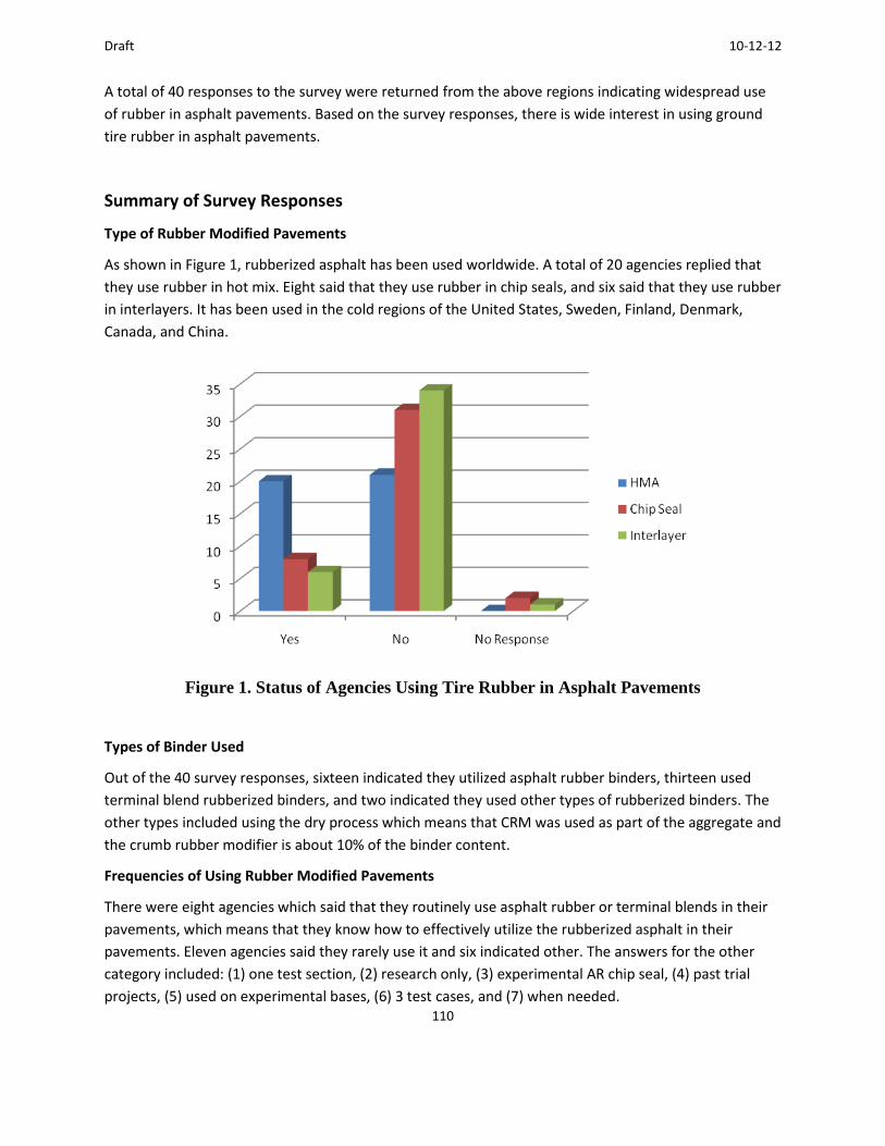
Draft 10-12-12
110
A total of 40 responses to the survey were returned from the above regions indicating widespread use
of rubber in asphalt pavements. Based on the survey responses, there is wide interest in using ground
tire rubber in asphalt pavements.
Summary of Survey Responses
Type of Rubber Modified Pavements
As shown in Figure 1, rubberized asphalt has been used worldwide. A total of 20 agencies replied that
they use rubber in hot mix. Eight said that they use rubber in chip seals, and six said that they use rubber
in interlayers. It has been used in the cold regions of the United States, Sweden, Finland, Denmark,
Canada, and China.
Figure 1. Status of Agencies Using Tire Rubber in Asphalt Pavements
Types of Binder Used
Out of the 40 survey responses, sixteen indicated they utilized asphalt rubber binders, thirteen used
terminal blend rubberized binders, and two indicated they used other types of rubberized binders. The
other types included using the dry process which means that CRM was used as part of the aggregate and
the crumb rubber modifier is about 10% of the binder content.
Frequencies of Using Rubber Modified Pavements
There were eight agencies which said that they routinely use asphalt rubber or terminal blends in their
pavements, which means that they know how to effectively utilize the rubberized asphalt in their
pavements. Eleven agencies said they rarely use it and six indicated other. The answers for the other
category included: (1) one test section, (2) research only, (3) experimental AR chip seal, (4) past trial
projects, (5) used on experimental bases, (6) 3 test cases, and (7) when needed.

Draft 10-12-12
111
Benefits of Using Rubber Modified Pavement
Based on the survey responses, there are many benefits of using rubber modified pavement. The
responses are summarized in Table 1.
Table 1. Benefits of Using Rubber Modified Binder
Agencies Benefits of using rubber modified binder
Alaska DOT & PF Resists studded tire wear.
Adds additional friction for winter driving.
Arizona DOT Increases durability.
Increases resistance to oxidative aging.
Increases resistance to reflective cracking.
Quiet and smooth.
Recycling of tires which would otherwise end up in landfills.
City of Calgary, Alberta Reduces reflective cracking.
Improves resistance to rutting.
Decreases traffic noise levels (Initial, but not maintained after 1 year
service).
Allows reduction in paving thickness.
Danish Road institute,
Denmark
Tire recycling, cracking resistance is better on some projects. Can use
effectively in areas with cobble pits. Less thickness required (60% of
conventional AC thickness is designed using asphalt rubber.
Delaware DOT Competition for polymer modified rubbers to keep costs lower.
Florida DOT Improves cracking resistance for dense-graded mixes.
Reduces raveling of open-graded friction courses.
Some improvement in rutting resistance by stiffening the binder.
Research conducted by the University of Florida documents some of
the benefits.
Georgia DOT Can provide reduced project costs while maintaining quality and at
the same time provides a productive outlet for end-of-life tires.

Draft 10-12-12
112
Jiangsu Transportation
Research Institute, China
Good durability and sliding stability.
Decreases noise pollution.
Uses a waste resource.
Nevada DOT Viscosity is very high, adhesion property is very good
New Jersey DOT Use asphalt rubber in Open-Graded Friction Courses. We have seen
benefits with the longevity of the OGFC along with the wet weather
accident and noise reduction seen with the use of OGFC.
Ohio DOT Good elasticity and flexibility.
Oklahoma DOT Better performance than virgin binder.
Ontario Ministry of
Transportation
Resistance to reflection cracking.
Pennsylvania DOT 2007 AR experimental seal coat project appeared to provide good
performance with minimal stone loss.
AR or terminal blend in HMA is best suited for gap-graded or OGFC
mixtures.
Penn DOT does not use OGFCs due to past use which resulted in
aggregate anti-skid material clogging up the openings resulting in
water retention and freezing causing more winter icing conditions and
resulting in higher rock salt application rates. Our use of gap-graded
HMA mixtures is mainly for SMA mixtures, but lack of AR blenders or
terminal blend limits its application in gap-graded SMA. However, we
have incorporated CRM in SMA in a dry process as a mastic stabilizing
agent on two SMA projects since 2009 which have performed well to
date.
Rhode Island DOT Better performance.
Saskatchewan Ministry
of Highways and
Infrastructure
Use of asphalt rubber would replace the addition of polymers in
mixes, therefore resulting in potential cost savings.

Draft 10-12-12
113
Sito Oy, Finland It's more flexible than ordinary asphalts and it is used to avoid
reflective cracking between concrete and asphalt pavements.
South Carolina DOT Recently started to use some terminally blended PG 76-22 on some
trial projects as an alternate modifier to SBS modified PG 76-22. We
have done some limited SAMI projects over old deteriorating concrete
pavements.
Svevia, Sweden Mitigates reflection cracking.
Improves adhesion of bitumen to aggregates.
Increases softening point of binder.
Increases fatigue life.
Challenges and Limitations of Using Rubber Modified Pavement
Due to various reasons including experience, equipment, materials, and construction issues, some
agencies expressed the following challenges (or limitations) of using rubber modified pavement shown
in Table 2.
Table 2. Limitations of Using Rubber Modified Binder
Agencies Limitations on using rubber modified binder
Alabama DOT Current market prices for CRM are higher than SBS in Alabama.
Another limitation is keeping the liquid asphalt tank agitated when
asphalt rubber is used.
Alaska DOT/PF Cost is high so use only on high volume roads that rut quickly.
Note that the "Dry Process" is used.
Arizona DOT Limited paving window due to temperature constraints.
Some mixes can be more difficult to compact and require more effort
on the part of the contractor.
Construction inspectors must have high degree of training and
experience in order to be assured all specifications are met.
Chang'an University,
Shanxi Province
High temperature for producing asphalt rubber.
More energy should be used for producing asphalt rubber.
More greenhouse gas will be produced.

Draft 10-12-12
114
High temperature performance of CRM is not better than SBS
modified asphalt mixture.
City of Calgary, Alberta Higher production costs.
Does not appear to maintain long-term noise reduction qualities.
Does not appear to stop all reflective cracking.
Delaware DOT Costs
Unknown long-term performance.
Georgia DOT Crumb rubber modified asphalt (rubber at 10% of liquid AC) is allowed
in Superpave mix, as an alternate to polymer modified asphalt, at
Contractor's discretion.
It is not allowed for SMA and OGFC.
Ministry of Highways and
Infrastructure-
Saskatchewan
Compaction can be difficult; some area may not have suitable
aggregates.
Only 2 contractors in province.
Limitations on available period in year due to weather restrictions.
Nebraska DOT Cost
Consistency
Availability
Nevada DOT Issues with moisture sensitivity have been encountered in the past.
Nova Scotia TIR Department tried one pilot project, but we were un-successful and
the project was cancelled.
Ohio DOT Cost based on trials in 2009.
Oklahoma DOT More expensive
Fewer sources
Ontario Ministry of
Transportation
Inexperience of hot mix industry with rubberized asphalt concrete.
Shortage of quality CRM meeting specifications.
Pennsylvania DOT Limited AR blending companies for onsite or project specific blending
of AR and limited terminal blend companies to provide terminal
blend. Mobilization of AR blenders results in higher costs which limits
their use due to current tight funding situation.
We have tried AR and CRM (dry process) in several dense-graded
HMA projects in the past several decades as experimental projects
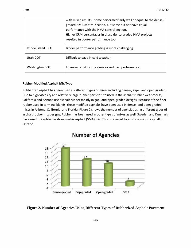
Draft 10-12-12
115
with mixed results. Some performed fairly well or equal to the dense-
graded HMA control section, but some did not have equal
performance with the HMA control section.
Higher CRM percentages in these dense-graded HMA projects
resulted in poorer performance too.
Rhode Island IDOT Binder performance grading is more challenging.
Utah DOT Difficult to pave in cold weather.
Washington DOT Increased cost for the same or reduced performance.
Rubber Modified Asphalt Mix Type
Rubberized asphalt has been used in different types of mixes including dense-, gap- , and open-graded.
Due to high viscosity and relatively large rubber particle size used in the asphalt rubber wet process,
California and Arizona use asphalt rubber mostly in gap- and open-graded designs. Because of the finer
rubber used in terminal blends, these modified asphalts have been used in dense- and open-graded
mixes in Arizona, California, and Florida. Figure 2 shows the number of agencies using different types of
asphalt rubber mix designs. Rubber has been used in other types of mixes as well. Sweden and Denmark
have used tire rubber in stone matrix asphalt (SMA) mix. This is referred to as stone mastic asphalt in
Ontario.
Figure 2. Number of Agencies Using Different Types of Rubberized Asphalt Pavement
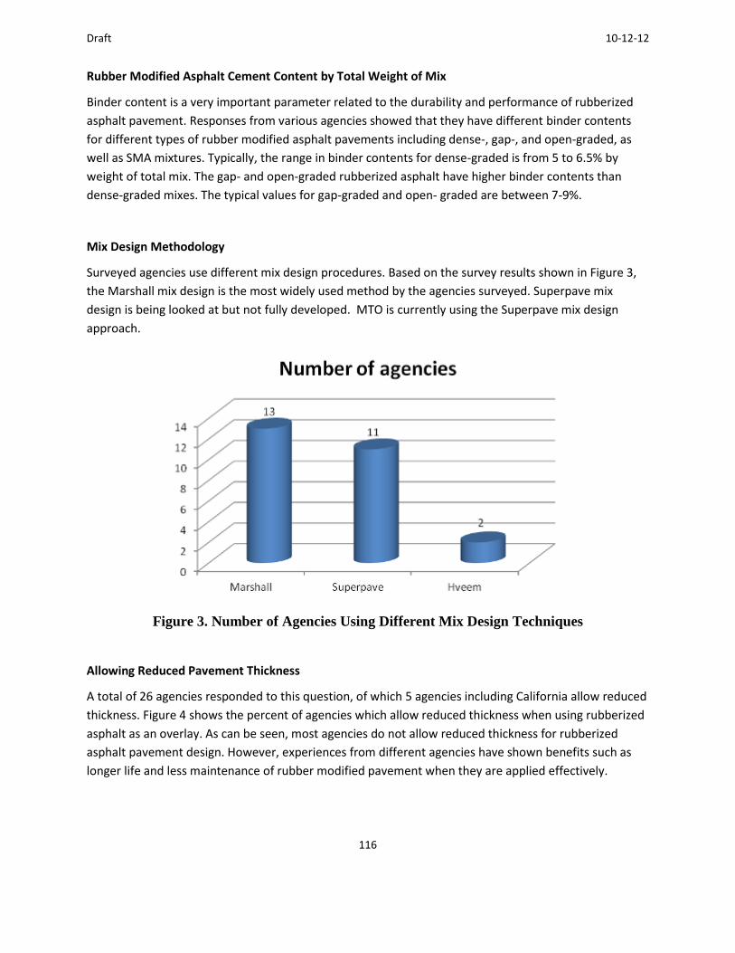
Draft 10-12-12
116
Rubber Modified Asphalt Cement Content by Total Weight of Mix
Binder content is a very important parameter related to the durability and performance of rubberized
asphalt pavement. Responses from various agencies showed that they have different binder contents
for different types of rubber modified asphalt pavements including dense-, gap-, and open-graded, as
well as SMA mixtures. Typically, the range in binder contents for dense-graded is from 5 to 6.5% by
weight of total mix. The gap- and open-graded rubberized asphalt have higher binder contents than
dense-graded mixes. The typical values for gap-graded and open- graded are between 7-9%.
Mix Design Methodology
Surveyed agencies use different mix design procedures. Based on the survey results shown in Figure 3,
the Marshall mix design is the most widely used method by the agencies surveyed. Superpave mix
design is being looked at but not fully developed. MTO is currently using the Superpave mix design
approach.
Figure 3. Number of Agencies Using Different Mix Design Techniques
Allowing Reduced Pavement Thickness
A total of 26 agencies responded to this question, of which 5 agencies including California allow reduced
thickness. Figure 4 shows the percent of agencies which allow reduced thickness when using rubberized
asphalt as an overlay. As can be seen, most agencies do not allow reduced thickness for rubberized
asphalt pavement design. However, experiences from different agencies have shown benefits such as
longer life and less maintenance of rubber modified pavement when they are applied effectively.

Draft 10-12-12
117
Figure 4. Agencies That Allow Reduced Thickness
Expected Lives of Chip Seals or Interlayers
Although AR chip seals have been used since the 1960s, the major cold region users of this treatment
are concentrated in the United States and China. Some agencies provided expected lives for their
asphalt rubber chip seal projects shown in Table 3. However, the actual treatment life depends on many
factors including existing pavement structure and condition, traffic, and environmental situations. Most
of the longer lives for AR chip seals or interlayers come with higher binder contents.
Table 3. Expected Life of Chip Seals or Interlayers
Agencies Expected life, years
Arizona DOT 5 to 10
California DOT 5 to 10
Delaware DOT 5
Florida DOT 15
Jiangsu Transportation Research Institute, China 10
Kansas DOT 5
Nevada DOT 5
Draft 10-12-12
118
Oklahoma DOT 10
Pennsylvania DOT 5
Rhode Island DOT 10
South Carolina DOT 5 to 7
Tennessee DOT 5
Recycling Asphalt Rubber Products
Table 4 summarizes the responses on recycling asphalt rubber products. Some agencies have
successfully recycled rubberized asphalt pavement or seal coats. Currently, the performance and
emissions of the recycled rubber products are not any worse than recycling other types of pavement as
long as the percentage of RAP from rubber products is kept low, such as less than 15 %.
Table 4. Agencies’ Experiences with Recycling Asphalt Rubber Products
Arizona DOT Gap-graded ARAC is milled and used as RAP.
California DOT
Caltrans allows using rubberized asphalt pavement as RAP for up to
15% into new hot mix asphalt.
Caltrans conducted a study in 2005, which showed that rubberized
asphalt concrete could be recycled by hot plant recycling, full depth
reclamation, and CIR. Since rubberized asphalt concrete can be
recycled into dense graded asphalt concrete, there is no need to mix
existing rubber into new rubberized asphalt concrete because it will
not increase rubber usage (Caltrans 2005).
Florida DOT We use lower percentages of rubber in our mixes (5% in dense-graded
mixes; 12% in open-graded mixes) so it hasn't been a problem, so far.
Kentucky DOT One job in 1993.
New Jersey DOT
Recycled a Plus Ride pavement back in the 1990s - a TRB report was
published at the time. Look for a report by Eileen Connolly and
Robert Baker.
Basically, there were no problems recycling 10% in a surface course.

Draft 10-12-12
119
Ontario Ministry of
Transportation
Just once in 1991 on Hwy 2 in Thamesville, Ontario. We managed to
re-use rubberized RAP in the new HMA. However emissions were
slightly elevated compared to the regular HMA.
Using Warm Mix Additives with Asphalt Rubber Products
Warm mix technology can reduce the mixing and construction temperatures of rubber modified asphalt
pavement, which can significantly reduce the emissions. Warm mix technologies can also lower the
viscosity of asphalt rubber binder, which can extend the construction season, increase opportunities for
cool temperature paving, and overcome long haul distances. Some agencies shown in Table 5 replied
that they have tried the warm mix technology with rubberized asphalt pavements.
Table 5. Warm Mix Technologies Used by Agencies on Rubber Products
Agencies Warm Mix Technologies
Alaska DOT/PF
Evotherm additive,
Contractor did not place mix as required so data is
unavailable.
California DOT
Advera, Evotherm, Sasobit are allowed.
Aztec Double Barrel Green, Engineering additives, and several
others are still in testing stage.
No problems with the use.
Chang'an University, China Sasobit and Evotherm warm mix additives have been used.
Danish Road Institute, Denmark The way we have tried crumb rubber in Denmark recently is
through the Road+ concept (Crumb rubber + Vestanamer).
Florida DOT Several - mainly Aztec Double Barrel Green foaming process.
New Jersey DOT
Have used a PG 64-22 modified with Evotherm to blend the
rubber into.
We were able to then keep the temperature below 300 F
(149C) and significantly reduced fumes.
Rhode Island DOT Sasobit, Sonnewarmix
Draft 10-12-12
120
Svevia, Sweden Cement and Wetfix
Conclusions and Recommendations
Based on the results from the survey of cold regions in the world, the following conclusions and
recommendations from this study appear warranted.
Conclusions
Based on the 40 responses from different countries, mostly from parts of the United States and Canada,
there is wide interest in using rubber in asphalt pavements. The following are the major conclusions
from the survey:
There are 15 agencies utilizing asphalt rubber binder, 13 using terminal blend rubber, and some agencies using asphalt rubber chip seals or as interlayers. This means that rubber product has been utilized in many parts of the world.
Based on the responses from agencies, the following are the benefits of using rubber modified
binders:
a. Improved performance; b. Competition with more expensive polymer modified binders; c. Improved elasticity; d. Improved durability and reduced aging; e. Quiet and smooth pavements; f. Improved crack resistance; g. Increased fatigue life; h. Possible reduction in paving thickness; i. Reduced wet weather accident rates with open-graded mixes; and j. Energy and environmental savings associated with recycling and reuse of waste tires.
There are barriers with using rubber products in asphalt pavement, such as the following:
a. Inexperience of hot mix industry; b. Shortage of quality CRM; c. Binder performance grading of asphalt rubber; d. Compaction issues; e. Weather restrictions; f. Cost, equipment, availability; g. High temperatures for production and construction; h. Limited paving window; and i. Need for an established Superpave mix design procedure.
Asphalt rubber can be used effectively in gap- and open-graded mixes. Asphalt binder contents in gap- and open-graded are normally higher than for dense-graded mixes. Terminal blends can

Draft 10-12-12
121
be used in dense- or open-graded mixes. The binder contents used by various agencies are summarized in the report.
The mix design procedures for using rubberized products vary. The most commonly used are Marshall, Superpave, and Hveem in descending order.
The pavement design methods include AASHTO, Mechanistic Empirical methods, and local empirical designs. The AASHTO method is the most widely used
Some agencies allow reduced thickness based on their experiences; however, most do not. They expect improved performance compared with conventional mixes.
High binder content AR chip seal and interlayer are more durable and effective for resisting reflective cracking.
Expected life of asphalt rubber chip seal varies based on locations. The range is wide from 5 to 15 years.
Rubberized asphalt pavement can be recycled. However, more studies are needed if RAP content is high.
Warm mix technology can be a big helper to reduce the limitations of using rubber product in pavements. Some agencies including Caltrans have successfully utilized several warm mix technologies.
Recommendations
The following recommendations are made based on rubber asphalt online survey results:
There are many different specifications on rubberized asphalt products. A more detailed study on specifications should be conducted. A summary report on the specifications used by various regions should help develop a more suitable specification for Ontario.
Research documentation was provided by some of the surveyed agencies. It would be helpful to synthesize the research results over the past to provide better guidance for agencies that are interested in increasing rubber usage.

Draft 10-12-12
122
Appendix C. MTO Rubber Specifications
SUPERPAVE 12.5FC 2 R - Item No.
SUPERPAVE 9.5 R-GAP GRADED - Item No.
Special Provision
Rubber Modified Hot Mix Asphalt
313.01 SCOPE
Subsection 313.01 of OPSS 313 is amended by the addition of the following:
This Special Provision covers the additional requirements for the construction of trial sections that
include the use of rubber material processed in Ontario from Ontario tire waste. The trial sections shall
incorporate rubber in the HMA using the wet process.
313.05 MATERIALS
313.05.01 Hot Mix Asphalt
Subsection 313.05.01 of OPSS 313 is deleted and replaced with the following:
The Materials used in the production of HMA shall be according to OPSS 1151, with the following
amendments:

Draft 10-12-12
123
The HMA types, lift and location of the control and trial sections are provided in Table R1.
1151.02 REFERENCES
Section 1151.02 of OPSS 1151 is amended by addition of the following:
American Society for Testing and Materials (ASTM) Standards
ASTM D5644 Test Methods for Rubber Compounding Materials - Determination of Particle
Size Distribution of Recycled Vulcanizate Particle Rubber
ASTM D6114 Standard Specification for Asphalt-Rubber Binder
ASTM D217 Standard Test Methods for Cone Penetration of Lubricating Grease
ASTM D5329 Standard Test Methods for Sealants and Fillers, Hot-Applied, for Joints and
Cracks in Asphaltic and Portland Cement Concrete Pavements
ASTM D36 Standard Test Method for Softening Point of Bitumen (Ring-and-Ball Apparatus)
ASTM D297 Standard Test Methods for Rubber Products-Chemical Analysis
State of California Laboratory Procedure
LP-11 Rotational Viscosity Measurement of Asphalt Rubber Binder

Draft 10-12-12
124
1151.03 DEFINITIONS
Section 1151.03 of OPSS 1151 is amended by addition of the following:
Ambient Ground: scrap tire rubber processed or ground at or above 20°C (68F) to provide irregularly
shaped, torn particles with relatively large surface areas.
Crumb Rubber (CR): scrap tire rubber that is reduced in size for use in asphalt paving materials such as
hot mix asphalt or asphalt cement or both.
Cryogenic Ground: scrap tire rubber processed or ground at temperatures low enough that the rubber
shatters.
Rubberized Asphalt Cement (RAC): asphalt-rubber binder; which is PGAC modified with crumb rubber
through the wet process.
Rubber Modified Asphalt (RMA): hot mix asphalt that contains crumb rubber added as an aggregate, as
RMA or as both. May also refer to CR added with the asphalt cement to the aggregates during mix
production of the HMA.
Superpave 12.5FC 2 R: means RMA that meets the requirements of Superpave 12.5FC 2 and contains
RMA that is produced using wet process-terminal blend.
Superpave 9.5 R-Gap Graded: means RMA with gap-graded aggregates having 9.5 mm (0.4in.) nominal
maximum size and contains RMA produced using the wet process-field blend. Requirements for
Superpave 9.5 R-Gap Graded are specified in this special provision.

Draft 10-12-12
125
Transition Area: the length of the section within which the change from one section to the next shall be
fully accomplished.
1151.04 DESIGN AND SUBMISSION REQUIREMENTS
1151.04.01 Design Requirements
Subsection 1151.04.01 of OPSS 1151 is amended by the addition of the following:
1151.04.01.07 Rubber Modified Asphalt
The RMA mix designs shall be according to the respective Superpave mix type specified in addition to
including CR using the process specified in Table R1 and according to the following:
a) Wet Process-Terminal Blend
The mix shall be designed to incorporate RMA in place of PGAC. Wet process-terminal blend RMA
shall be produced by the PGAC supplier at their asphalt terminal.
b) Wet Process-Field Blend
The mix shall be designed to incorporate RMA in place of PGAC. Wet process-field blend RMA shall
be produced at the hot mix asphalt plant using a field blending plant.
The Superpave 9.5 R-Gap Graded mix design and JMF shall be according to the requirements specified in
Table R2, Table 3 of OPSS 1151, and LS-309. For mix design purposes, the RMA shall be produced in the
laboratory according to the following procedure:

Draft 10-12-12
126
Heat up the base PGAC to 180oC (356F). Add 18-20% CR by weight of the PGAC while continuously blending the compound.
Continue blending the RMA for 45 minutes at 180oC (356F).
1151.04.02 Submission Requirements
Subsection 1151.04.02 of OPSS 1151 is amended by the addition of the following:
The Contractor shall submit a plan and schedule to the Contract Administrator within two weeks of
contract award describing how the Contractor will meet all the requirements of this non-standard
special provision for review and approval including the following information in writing:
a) Special actions to be taken to assure that the CR will be available meeting the requirements of the
Contract Documents, including that the CR processor selected by the Contractor or asphalt cement
supplier or both can provide the material required for the Contract, and how the Contractor will
assure that the CR processor selected has sufficient time to produce the quantity of CR required.
b) Information such as CR supplier’s name, address, CR gradation, materials safety data sheet (MSDS),
method and equipment used to mix CR into mix, CR dosage, RMA reaction time, mixing
temperature, RMA storage conditions and any need for agitation, RMA blending location (hot mix
asphalt plant vs. asphalt supplier’s terminal) shall be provided.
c) Special actions to be taken to prevent swelling of the briquettes during the mix design.
d) Special actions to be taken to assure that the CR will be homogeneously distributed in the RMA.
e) Special actions to be taken to prevent pick-up during compaction of the RMA.
f) Product information on CR including information on how it was ground, whether cryogenic or
ambient or both, shall be submitted with the mix design.
Draft 10-12-12
127
g) A letter from the CR supplier indicating that the CR they are supplying is produced in Ontario from
tires scrapped in Ontario.
No RMA shall be placed on any trial section until the Contract Administrator acknowledges receipt of the
plan and schedule in writing. Separate mix designs shall be submitted for each RMA type and for the
control mix.
1151.05 MATERIALS
Section 1151.05 of OPSS 1151 is amended by addition of the following:
1151.05.06 Rubber Modified Asphalt and Rubberized Asphalt Cement
1151.05.06.01 General
Materials for the RMA shall conform to OPSS 313 except as amended by this special provision. It is the
Contractor’s responsibility to identify a facility to produce the mixes in accordance with the supplier’s
instructions for the use of their materials. The Contractor is responsible for obtaining from the suppliers
any and all information required for the proper preparation, handling, storage and use of their
materials.
The Contractor shall be solely responsible for obtaining materials, producing mixes, transportation,
storage and use of all materials. The Contractor shall assure that the RMA is produced to prevent any
deleterious effects to the finished product. The Contractor shall be responsible for ensuring cross
contamination does not occur between the sections.
The Contractor shall contact Ontario Tire Stewardship (OTS), at either of the contact information below,
who will facilitate the sourcing of the field blending plant, needed for producing Superpave 9.5 R-Gap
Graded. The field blending plant shall only be sourced through OTS. The Contractor shall be responsible

Draft 10-12-12
128
for the cost of supplying and operating the field blending plant. The Contractor shall allocate sufficient
space at the hot mix asphalt plant to house the field blending plant. An area of about 30 m x 20 m would
be sufficient for the field blending plant. The Contractor shall provide points of contact for supply lines
from and to the field blending plant. The Contractor shall cooperate with the operator of the field
blending plant and harmonize the operation of the field blending plant with the hot mix asphalt plant in
order to produce the RMA mix meeting the requirements of the Contract Documents. The Contractor
shall be responsible to supply and feed the CR into the field blending plant.
Andrew Horsman, Executive Director
Ontario Tire Stewardship
405 the West Mall, Suite 500
Toronto, ON M9C 5K7
Tel: 416-626-9185
Jennifer Barbazza, Manager, Operations & Special
Projects
Ontario Tire Stewardship
405 the West Mall, Suite 500
Toronto, ON M9C 5K7
Tel: 416-916-4818
1151.05.06.02 Crumb Rubber
The CR shall be processed from whole passenger vehicle tires. Heavy equipment tires shall not be used.
Use of uncured or devulcanized rubber will not be permitted. CR shall be in the form of ambient or
cryogenic ground rubber, or both. The CR shall be produced in Ontario from tires scrapped in Ontario.
CR shall not contain more than 0.01% of wire and 0.05% fabric by weight. CR shall be free of other
contaminants. The CR shall be dry and free-flowing and not produce foaming when blended with the
PGAC. The CR shall have a specific gravity in the range of 1.1 to 1.2, as determined according to ASTM D
297.
The CR shall meet the gradation requirements specified in Table R3 determined according to ASTM
D5644. No particles shall exceed a length of 5 mm as measured on any axis.
The Contractor shall contact Ontario Tire Stewardship (OTS), at the above contact information, who will
facilitate the sourcing of the CR.
Draft 10-12-12
129
1151.05.06.03 Aggregates
Aggregate properties for RMA shall meet the requirements of Superpave 12.5FC 2 specified elsewhere
in the Contract Documents. Coarse and fine aggregate properties for Superpave 9.5 R-Gap Graded shall
meet the requirements of Superpave 12.5FC 2 specified elsewhere in the Contract Documents.
1151.05.06.04 Rubberized Asphalt Cement
CR added to the RMA shall meet the gradation requirements specified in Table R3 determined according
to ASTM D5644. Wet-terminal blend RMA shall be produced as a Type III Asphalt Rubber Binder
according to ASTM D6114. CR dosage by mass of wet-terminal blend RMA shall be 10% to 15%. Wet-
field blend RMA (after reaction) shall meet the requirements found in Table R4. CR dosage by mass of
wet-field blend RMA shall be 18% to 20%. For the production of the RAC, parameters such as CR
gradation, mixing method and equipment, dosage, reaction time, mixing temperature, storage
conditions and need for agitation, blending location (project site vs. asphalt supplier’s terminal) shall be
determined by the Contractor.
When the RMA supplier specifies a CR gradation with additional restrictions, the CR shall also meet the
RMA supplier’s gradation requirements. The CR material, PGAC and any antistripping additives required
shall be compatible to ensure a good dissolution and reaction time. RMA produced shall be a
homogenous mixture of CR and asphalt cement.
In case of terminal blend, the following asphalt cement suppliers have indicated their ability to supply
the RAC:
a) Bitumar; b) Coco; c) McAsphalt; d) Shell

Draft 10-12-12
130
1151.07 PRODUCTION
1151.07.01 Anti-Stripping Additives
Subsection 1151.07.01 of OPSS 1151 is amended by addition of the following:
When an anti-stripping agent is to be incorporated into the mix, the Contractor shall contact and consult
with each supplier to determine whether or not the proposed anti-stripping agent is compatible with
the RMA or RMA or both. In those cases where a supplier deems that the anti-stripping agent is
incompatible, that anti-stripping agent shall not be used and the Contractor shall select and employ
another anti-stripping agent that the suppliers indicate is compatible with the mix and RAC.
1151.07.03 Field Blending Plant
The Contractor shall contact OTS a minimum of 6 weeks prior to paving Superpave 9.5 R-Gap Graded to
coordinate delivery and operation of the field blending plant. OTS contact information is provided
earlier in this special provision.
313.07 CONSTRUCTION
313.07.06.01 Operational Constraints
Clause 313.07.06.01 of OPSS 313 is amended by addition of the following:
The Contractor shall provide a minimum of 7 Days notice in writing to the Contract Administrator and to
the Ministry’s Regional Head of Quality Assurance Section before paving any trial section.

Draft 10-12-12
131
313.07.06.02 Paving
Clause 313.07.06.02 of OPSS 313 is amended by addition of the following:
The Contractor shall construct the control section and trial sections as indicated in Table R1, full width
including shoulders. Transition areas shall be less than 50 m in length at the start of the trial and control
sections. The Contractor shall adjust the paving and compaction operations to eliminate roller pick-up
and provide a smooth surface without tearing, cracking, or shoving.
313.07.15 Sampling
Subsection 313.07.15 of OPSS 313 is amended by the addition of the following clause:
313.07.15.06 Rubber Modified Asphalt
Samples shall not be taken from the transition areas. In addition to other samples specified in the
Contract Documents, the Contractor shall procure RMA samples of a minimum quantity specified in
Table R5 for each of the control and trial sections.
Sample labeling shall include: highway number, highway direction, lane number, contract number,
section (trial or control), mix type, corresponding Lot/Sublot numbers, station, date sampled. The
Contractor shall deliver the samples specified in Table R5 to the address below:
c/o Seyed Tabib
Bituminous Section, MERO
Shipping and Receiving
Room 15, Building C
1201 Wilson Ave,

Draft 10-12-12
132
Toronto, ON M3M 1J8
Section 313.07 of OPSS 313 is amended by the addition of the following subsection:
313.07.19 Identification of RMA Paving Limits
The Contractor shall provide to the Contract Administrator, no later than 7 Days after completion of
RMA paving, an as built sketch identifying the stations as well as the GPS data for the RMA paving limits.
The GPS data shall be geo-referenced and NAD83 geographic coordinates (latitude, longitude) shall be
used. Geographic coordinates (latitude, longitude) shall be provided within metre-level accuracy.
313.08 QUALITY ASSURANCE
313.08.01.02.01 Lot Size
Clause 313.08.01.02.01 of OPSS 313 is amended by the addition of the following:
Each mix type for the trial section shall be considered as a single lot with a minimum of three sublots.
313.08.01.02.03 Basis of Acceptance
Clause 313.0.8.01.02.03 of OPSS 313 is amended by the addition of the following:
a) Acceptance of Crumb Rubber
i. All CR shall meet the gradation requirements specified in Table R3 determined according to
ASTM D5644.

Draft 10-12-12
133
b) Acceptance of Rubber Modified Asphalt (RMA)
i. Acceptance and pay adjustment of the RMA containing RAC-terminal blend shall be determined
accordance to the respective mix type HMA requirements specified elsewhere in the Contract
Documents.
ii. Acceptance and pay adjustment of the Superpave 9.5 R-Gap Graded shall be according to
requirements for Superpave 9.5 specified elsewhere in the Contract Documents with the
exception of VMA and coarse and fine aggregate physical properties. VMA will not be
considered an acceptance criterion for Superpave 9.5 R-Gap Graded. Coarse and fine aggregate
physical properties for Superpave 9.5 R-Gap Graded shall be according to requirements for
Superpave 12.5FC 2 specified elsewhere in the Contract Documents. Aggregate gradation for
Superpave 9.5 R-Gap Graded shall be according to Table R2.
iii. RMA containing RAC wet-terminal blend will be rejectable if there are clumps of CR in the RMA
visible to the naked eye.
c) Acceptance of Rubberized Asphalt Cement (RAC)
i. Acceptance of the RAC wet-terminal blend shall be determined according to the respective
requirements for the PGAC grade specified according to OPSS 1101. Additionally, to be
acceptable the RAC wet-terminal blend shall meet the Type III Asphalt Rubber Binder
requirements of ASTM D6114.
ii. Acceptance of the RAC wet-field blend shall be according to Table R4.
313.08.01.02.04.01 General
Clause 313.08.01.02.04.01 of OPSS 313 is amended by the addition of the following:
The Owner will use LS-292 for determination of the asphalt cement content for the RMA, therefore, the
referee laboratory shall also follow LS-292 (ignition oven).

Draft 10-12-12
134
313.09 MEASUREMENT FOR PAYMENT
313.09.01.01
Clause 313.09.01.01 of OPSS 313 is amended by the addition of the following item:
Superpave 9.5 R-Gap Graded
313.10 BASIS OF PAYMENT
313.10.01.01
Clause 313.10.01.01 of OPSS 313 is amended by the addition of the following item:
Superpave 9.5 R-Gap Graded - Item
313.10.01.02.02.04 Payment Factor for Voids
Clause 313.10.01.02.02.04 of OPSS 313 is deleted in its entirety and replaced with the following:
For RMA mixes, as long as the lot mean air voids are between 2.5 and 5.5%, the payment factor for
voids, PFVOIDS, shall be equal to either:
a) PFGAC, if the PFGAC is less than 1.0; or,
b) 1.0, if the PFGAC is equal to or greater than 1.0.
Otherwise, if the lot mean air voids are outside the 2.55.5% range, the PFVOIDS shall be considered to be
0.5.

Draft 10-12-12
135
313.10.01.02.02.06 Payment Factor for Combined Mix Properties and Compaction
Clause 313.10.01.02.02.06 of OPSS 313 is amended by the addition of the following:
For RMA mixes, as long as the lot mean compaction is between 90.5 and 98.0 %, the payment factor for
compaction, PFC, shall be equal to either:
a) PFM, if the PFM is less than 1.0; or,
b) 1.0, if the PFM is equal to or greater than 1.0.
Otherwise, if the lot mean compaction is outside the 90.5-98.0 % range, the PFC shall be considered to
be 0.65.
Table R1
Trial Sections
Trial Section Pavement Course Location (Stations) Mix Type
Wet Process-Field Blend Surface 14+500 to 17+500 Superpave 9.5 R-Gap
Graded
Wet Process-Terminal Blend Surface 11+500 to 14+500 Superpave 12.5FC 2 R
Control Section Surface
Remainder of the contract to
the west of Wet Process-
Terminal Blend Section
Superpave 12.5FC 2

Draft 10-12-12
136
Table R2
Superpave 9.5 R-Gap Graded Properties
Hot Mix
Asphalt
Type
Percentage Passing by Dry Mass of Aggregates
Traffic
Category
Base
PGAC
Grade
% Air
Voids
%
VMA
min.
ACBID
(%) Sieve Size, mm
12.5 9.5 4.75 2.36 1.18 0.075
Superpave
9.5 R-Gap
Graded
100 90-
100 28-42 15-25 5-15 2-7 C 58-28 4 18 7.0
Table R3

Draft 10-12-12
137
Gradation Requirements for Crumb Rubber
Process Sieve Percent Passing Sieve by Mass
Wet-Terminal Blend
(see Note 1)
2.36 mm 100
Wet-Field Blend
2.36 mm 100
2.00 mm 98 – 100
1.18 mm 45 – 75
600 µm 2 – 20
300 µm 0 – 6
150 µm 0 – 2
Notes:
1. The RAC supplier shall select a gradation suitable for producing a Type III Asphalt Rubber Binder
according to ASTM D6114 and this non-standard special provision in addition to meeting the minimum
requirements of OPSS 1101 for the PGAC grade specified elsewhere in the Contract Documents.
Table R4
Requirements for Field Blend RAC (after reaction)
Test Parameter Test Method Specification Limit
Field Viscosity @ 191°C (375°F),
centipoises (see Note 1)
California Laboratory
Procedure LP-11 1500 – 4000
Cone Penetration @ 25°C, 0.1 mm ASTM D 217 25 – 70
Resilient @ 25°C, % Rebound ASTM D 5329 18 minimum
Field Softening Point, °C ASTM D 36 52 – 74
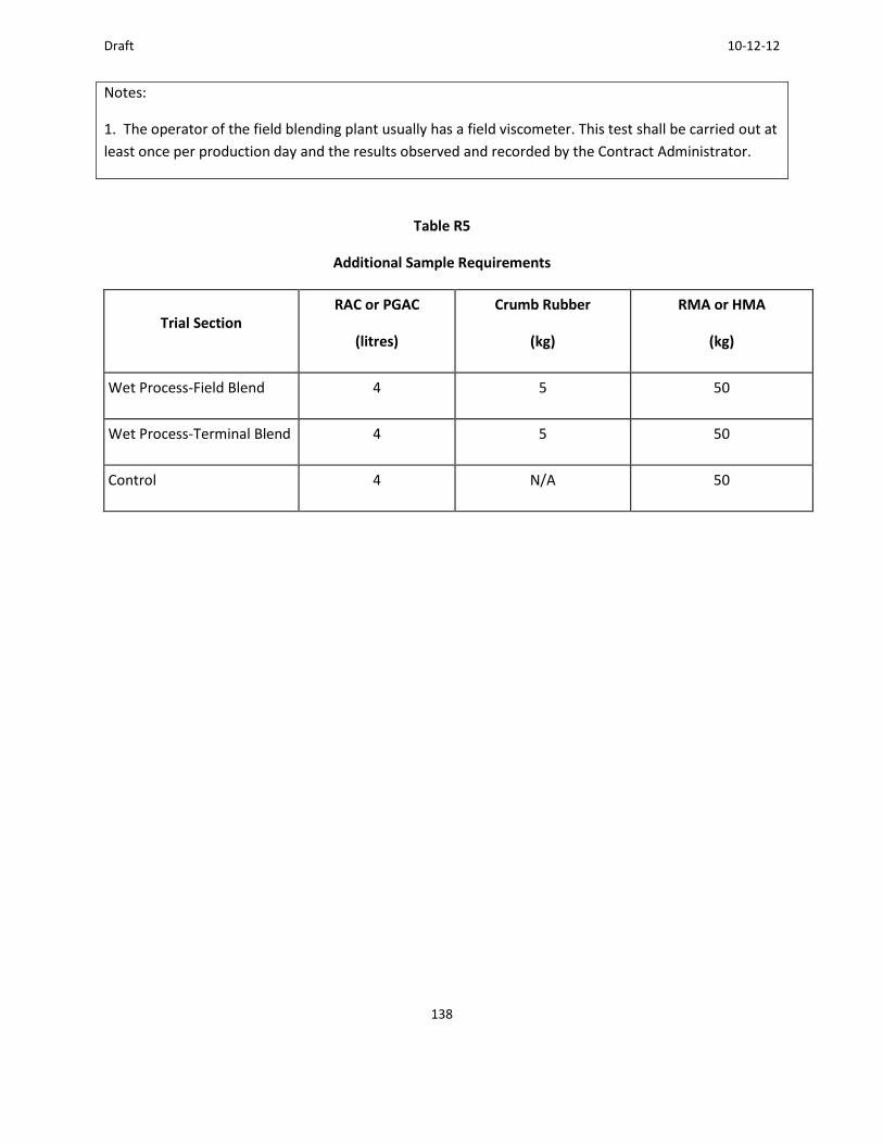
Draft 10-12-12
138
Notes:
1. The operator of the field blending plant usually has a field viscometer. This test shall be carried out at
least once per production day and the results observed and recorded by the Contract Administrator.
Table R5
Additional Sample Requirements
Trial Section RAC or PGAC
(litres)
Crumb Rubber
(kg)
RMA or HMA
(kg)
Wet Process-Field Blend 4 5 50
Wet Process-Terminal Blend 4 5 50
Control 4 N/A 50

Draft 10-12-12
139
Appendix D. Laboratory Mix Design for Rubber Modified Asphalt
Background
Currently, the MTO allows the terminal blend and field blend process in their specifications. At this time,
the semi wet and dry processes are not being used.
In the terminal blend process, the crumb rubber is blended at the terminal to meet ASTM D 6114, Type
3. MTO, however uses from 10-15 % crumb rubber by weight of the asphalt cement. The rubber
gradation passes the 2.36 sieve as shown in the specifications. Asphalt suppliers have indicated that
they use an ultrafine rubber with particles smaller than 0.6 mm (passing the 30 sieve) for their terminal
blend products
For the field blended asphalt rubber, the crumb rubber is blend on site using 18-20 % crumb rubber by
weight of the asphalt cement. The asphalt cement is heated to 180-190C (356-375F) and crumb
rubber is added. The rubber is digested for 45 minutes to 1 hour prior to its use.
The expected impacts of the added rubber are as follows:
• The binder content for the mixture should increase, particularly for the gap-graded mixes. • The crumb rubber provides bulk to the asphalt cement. • Range of binder content increase is about 10-20%.
Laboratory Mix Design Considerations
When completing a mix design for rubberized asphalt concrete, the aggregate selection process remains
unchanged from standard mix design procedures. Aggregates need to be blended in the right
proportions to meet the gradation specifications. The rubber particles act like aggregate, particularly in
the field blended binders and may be in part responsible for any swelling of the mix.
For the terminal blends, the rubberized asphalt cement is pre-blended and ready to be mixed with the
aggregate. The rubber has been digested at the terminal: however, lab samples will require stirring
while hot to uniformly distribute the crumb rubber. Generally, the aggregate is dense-graded according
to the specifications.
For the field blended process, the asphalt cement is heated to 180C (356F) and 18-20 % crumb rubber
is added by weight of the AC. The mixture is blended continuously for 45 minutes and used immediately.
The product is normally used with a gap-graded aggregate.

Draft 10-12-12
140
The modified asphalt cements are similar to polymer modified asphalt cement. Standard temperature
viscosity guidelines do not apply. Typical mixing and compacting temperatures are as follows:
• Terminal blends: follow manufacturers recommendations • Field blends
• Rubberized asphalt cement (RAC) – 163 to 182C (325 to 360F)
• Aggregate - 143 to 164 C (290 to 327F)
• Compaction temperature -143 to 149C (290 to 300F)
Briquette swell needs to be addressed in mix design. After compaction, there is a potential for swell,
particularly in the field blends RAC. Swelling results in a loss of density and can vary with the different
processes. In the Superpave mix design process, each lab needs to check for swell. In the past, labs in
Ontario have used a weight to control the swell. It needs to be placed immediately after compaction as
swelling can occur on release of the load by the Gyratory compactor. The following steps have been
used to control the swell;
• Leave the sample under load in the Gyratory compactor for 15 minutes. This allows the sample to cool as well.
• Place a 15 kg weight on the sample after it has been removed from the compactor
• Do not extrude the sample until the sample reaches a temperature of 35C (95F).
Mix designs with crumb rubber are still new in Ontario. This process will likely evolve as more projects
are placed. The following section provides some detailed designs for projects constructed in 2011.
Detailed Mix Designs
The remainder of the Appendix provides an example of detailed SuperPave mix design for a terminal
blend and a field blend rubberized modified asphalt mix.

Draft 10-12-12
141
Example of Terminal Blend Mix Designs

Draft 10-12-12
142
Example of Field Blend Mix Designs

Draft 10-12-12
143
Appendix E. Summary of 2011 RMA projects
Introduction
In 2011, the MTO led several pilot projects to evaluate the feasibility of construction of both field and
terminal blend rubberized asphalt. The projects constructed, as well as some of the preliminary
observations, are summarized in this appendix. This was a cooperative effort with the OTS which assisted
with the supply of the rubber, the blending equipment, and funding for the projects. The full report on
these projects which includes project data, photos and more can be obtained from the OTS.
Projects Constructed
Table 1 summarizes the 6 projects planned for construction during the 2011 season. Mohamed Hegazi of
OTS and Seyed Tabib of MTO provided input on the completed projects. As can be seen in Table 1, only
3 of the projects were completed as planned using the rubberized asphalt. They others were either paved
using a conventional hot mix or delayed until 2012. It should be noted that all of the projects completed
as planned were accomplished by one contractor.
Table 1. 2011 project summaries
TABLE 1 2011 PROJECT SUMMARIES
Highway Mix type
Lane
(km)
Placed
Tonnage
Placed
Date
Completed Comments
Highway 3 Field blend SP 9.5 R
Gap-Graded 0 0
Rubber
section has
been
cancelled
Problems with
rubber gradation
and mix design.
Highway 60 Field blend SP 12.5 R
Dense-Graded 0 0
Rubber
section has
been
cancelled
Problems with the
mix design and
blending
equipment.
Highway 7 Field blend SP 9.5 R 6 3600 Completed Night paving. Barrel

Draft 10-12-12
144
Gap-Graded in October
2011
stuck
Terminal Blend SP 12.5
FC2 R Dense-Graded 5.6 3100
Hot Mix Asphalt SP
12.5 FC2 Dense-Graded 2.8 4800
Highway 35
Field Blend SP 12.5FC1
R Gap-Graded 6 4400 Completed
in October
2011
Hot Mix Asphalt SP
12.5 FC1 Dense-Graded 13.5 11200
Highway 115
Field Blend SP 12.5 FC2
R Gap-Graded 6 4100 Completed
in October
2011
Hot Mix Asphalt SP
12.5 FC2 Dense-Graded 3 3900
Highway 24 Field blend SP 9.5 R
Gap-Graded 0 0
Rubber
section has
been
cancelled
Problems with mix
design and blending
equipment.
Highway 60
Terminal blend SP 12.5
R Dense-Graded 4 2600
Completed
in June 2011
Hot Mix Asphalt SP
12.5 Dense-Graded 17.6 12400
Highway 35 Terminal blend SP 12.5
R Dense-Graded 0 0
Delayed
until 2012.
Project carried over
to 2012.
R = Rubber Modified Asphalt Mix
Highway 3 project
Some of the issues associated with this project included:
Initial rubber samples did not meet gradation requirements.
On July 26, 2011, OTS received an email regarding a second sample which did not meet
gradation requirements.

Draft 10-12-12
145
The contractor had difficulties obtaining a mix design and had many delays due to difficulty with
rubber sample gradations, etc.
On August 11, 2011, Fath Industries (supplier of the blending unit) did a site visit at the
contractor’s plant to view connections and perform required modifications.
On September 1, 2011, DBA Engineering was contracted to develop a mix design since the
contractor had difficulty obtaining one.
In November 2011, the contractor informed OTS that the contract has been deferred until the next year.
Highway 60
Some of the issues associated with this project included the following:
DBA Engineering was contracted to develop a mix design for the project, but it took longer than
expected to deliver to the mix design to the contractor.
Swelling in the mix design was discovered and was corrected by slightly changing the gradation
of the crumb rubber to the finer side of the specifications.
Once the blending equipment was set up, a faulty part was discovered which caused the
equipment to not produce any asphalt rubber. Fath Industries tried to take care of the issue as
soon as possible, but the contractor was instructed to continue with conventional hot mix while
the part was held up in customs.
As a result, the project ended up to be placed using conventional mix.
Highway 7
This project was placed in 2011 and had few issues including:
The contractor had questions on the mix design that were answered by Anne Stonex (AMEC) and
Mark Belshe (Rubber Pavements Association).
There was a lot of rubber wasted due to clumping while it was stored outdoors; therefore, more
rubber was required to be shipped during production.
Paving took place at night without significant problems. The contractor obtained samples for the OTS and
the University of Waterloo. A 300 kg of sample per mix was required (one conventional mix, one
terminal blend rubber mix, one field blend rubber mix). The paving operations went smoothly, but the
rubberized mix was reported to be harder to work with. The blending unit was able to keep up with the
production quantity requirements of the contractor’s plant.
Highway 35
This project was constructed by the same contractor who constructed the Highway 7 project. Some of the
issues on the project included:
Draft 10-12-12
146
During the paving, the contractor had requested extra bags of rubber to be delivered in short
notice and OTS in cooperation with CRM, Inc. were able to deliver the rubber.
Any others
Paving took place in October 2011. A summary of the observations are as follows:
Weather caused few delays in the paving of this highway section.
The contractor collected samples for OTS and the University of Waterloo. A 300 kg of sample
per mix was required (one conventional mix, one field blend rubber mix).
Paving operation was smooth.
It was noted that multiple parties that had conducted site visits liked the look and feel of the
rubber asphalt.
The paving operators did not like the material as it was “too hard to work with.”
The blending unit was able to keep up with the production quantity requirements of the
contractor’s plant.
Highway 115
The contractor who paved Highway 7 and 35 also paved this project. The paving took place in October
2011. The one issue encountered on this project was that the contractor required extra bags of rubber to be
delivered in short notice, which OTS and CRM, Inc. were able to do.
The paving operation went smoothly with a few minor problems:
Weather caused a few delays in the paving of this highway section.
The contractor collected samples for OTS and the University of Waterloo. A 300 kg sample per
mix was required (one conventional mix, one field blend rubber mix).
Paving operation was smooth.
It was noted that multiple parties that had conducted site visits liked the look and feel of the
rubber asphalt.
The paving operators did not like the material as it was “too hard to work with.”
The blending unit was able to keep up with the production quantity requirements of the contactors
plant.
Highway 24
This project was scheduled as a rubberized asphalt project. The contractor requested a mix design from
one of the Ontario labs in September 2011. Because of the late start, the contractor asked the MTO to
switch the job to a conventional mix. Some of the issues which led to the delays were as follows:
During the initial phases, there was difficulty obtaining the right gradation of crumb rubber to
send to the contractor.
Modifications to the asphalt plant to accommodate for the blending unit were an issue for the
contractor.

Draft 10-12-12
147
Summary of Observations
Only 3 of the 6 projects were completed as planned. These projects went smoothly, even though
contractor personnel reported the mix to be more difficult to work with. The initial reports show that the
pavements look good. Only time will tell how well they will perform.
Preliminary Conclusions
It is too early to determine how these projects will perform over the long run. Testing planned by the
University of Waterloo and Queens University will help with the prediction of the long term performance.
These tests are not available at this point in time. The tests are expected to be completed by the end of
201`2.
Draft 10-12-12
148
Appendix F. Crumb Rubber Sample Examination Performed by the MTO
By
Carole Anne MacDonald and Seyed Tabib
January 12, 2012
This appendix describes the type of analysis performed on a sample of Crumb Rubber Modifier (CRM)
that was examined in the Microscopy Laboratory of the Materials Engineering & Research Office, MTO.
The CRM sample was supplied by Ontario Tire Stewardship (OTS) for use on 2011 MTO Rubber Modified
Asphalt (RMA) contracts. It is understood that the CRM sample has been subjected to two stages of
grinding: 1) an initial cryogenic grind, and 2) a secondary ambient grind. Keeping this in mind it was
attempted to distinguish the different types of grinding during the examination.
Material As Received
The material was initially examined in an as received condition to identify the basic nature of the
material and any obvious contaminants such as fibers, metals, plastics, etc. No steel or other metals
were observed. No plastics or cellulose fibers were observed.
Initial observations indicate the material consists mainly of black cryogenic (Photo 4) and ambient
ground (Photos 4 and 5) rubber with particle sizes generally less than 2.36 mm. White rubber (Photo 6),
synthetic fibers (Photos 7 to 13), and mineral grains were also observed. Synthetic fibers and mineral
grains occur mainly as individual particles and individual fibers within the sample, but may also occur
adhered to or partially or wholly embedded within the rubber particles (Photos 9, 10 and 13). Clusters or
bunches of synthetic fibers were also observed and presumably occurred from the action of rolling or
vibration on a mesh screen during fractionation of the material. The same “bunching” was observed
during sieving of the material for this examination (Photo 8). Table 1 lists the materials found in this
sample and their identifying properties.

149
Table 1. Materials present in the crumb rubber sample provided.
Material Size Range Morphology Colour Optical Properties Description
Black cryogenic ground rubber
<75µm – 2 mm Particle; cubical Black Opaque Generally smooth reflective surfaces, conchoidal to plumose fracture surfaces
Black ambient ground rubber
<75µm – 5 mm Particle, cubical with irregular to elongate shapes common
Black Opaque Rough, dull surfaces, high surface area to volume ratio as compared with cryogenic ground. Often has a “ragged” appearance.
White rubber (cryogenic and ambient ground)
0.1 mm - 4 mm Particle, cryogenic and/or ambient ground
White Opaque Surfaces of cryogenic particles tend to appear rougher and less reflective as compared with cryogenic ground black rubber
Black synthetic fibre
up to 3 cm long,
<1/5 mm diameter
Straight, not flexible; round in cross section
Black Opaque Melts under flame
Only one fibre of this nature was observed (Photo 12)
Type 1 fibre
Transparent to translucent synthetic fibres
1 to 8 mm long,
<5 - 15 µm diameter
Flexible fibres
Occurs as single fibres and wound composite strands
Straight to wavy or crimped
Colourless to white,
rare blue to red
Transparent to translucent;
Anisotropic
Parallel to undulose extinction
index of refraction > n=1.515
3 – 4th
order birefringence (up to 0.20); +ve elongation
Chopped fibres;
Melts in flame, does not burn
Fibres often appear wavy or crimped
Consistent with the published optical data for the Aramid-Polyamide-Polyester types of synthetic fibres. Most closely matches polyester or Aramid
1
Type 2 fibre
Yellow to brown synthetic fibres
Up to 7 mm long,
up to
0.2 mm wide
Composite strands - numerous fibres clustered together to make a single fibre, individual strands are <5 µm wide
Straight
Yellow to orange brown
Translucent
Anisotropic
Parallel extinction
index of refraction > n=1.515
~1st
to 2nd
order birefringence
+ve elongation
Chopped fibres;
Coating or colouring on outer surface of fibres makes birefringence difficult to estimate
Melts in flame, does not burn
Consistent with the published optical data for the Aramid-Polyamide-Polyester types of synthetic fibers
1
Silicate 0.25 mm to Particle, cubical Colourless, Transparent to Conchoidal fracture surfaces
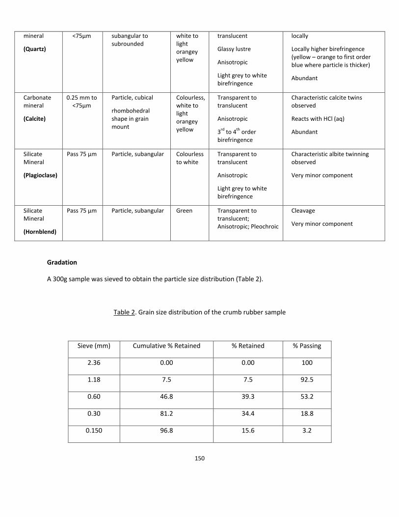
150
mineral
(Quartz)
<75µm subangular to subrounded
white to light orangey yellow
translucent
Glassy lustre
Anisotropic
Light grey to white birefringence
locally
Locally higher birefringence (yellow – orange to first order blue where particle is thicker)
Abundant
Carbonate mineral
(Calcite)
0.25 mm to <75µm
Particle, cubical
rhombohedral shape in grain mount
Colourless, white to light orangey yellow
Transparent to translucent
Anisotropic
3rd
to 4th
order birefringence
Characteristic calcite twins observed
Reacts with HCl (aq)
Abundant
Silicate Mineral
(Plagioclase)
Pass 75 µm Particle, subangular Colourless to white
Transparent to translucent
Anisotropic
Light grey to white birefringence
Characteristic albite twinning observed
Very minor component
Silicate Mineral
(Hornblend)
Pass 75 µm Particle, subangular Green Transparent to translucent; Anisotropic; Pleochroic
Cleavage
Very minor component
Gradation
A 300g sample was sieved to obtain the particle size distribution (Table 2).
Table 2. Grain size distribution of the crumb rubber sample
Sieve (mm) Cumulative % Retained % Retained % Passing
2.36 0.00 0.00 100
1.18 7.5 7.5 92.5
0.60 46.8 39.3 53.2
0.30 81.2 34.4 18.8
0.150 96.8 15.6 3.2
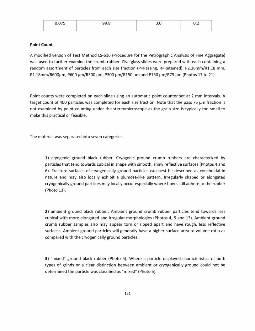
151
0.075 99.8 3.0 0.2
Point Count
A modified version of Test Method LS-616 (Procedure for the Petrographic Analysis of Fine Aggregate)
was used to further examine the crumb rubber. Five glass slides were prepared with each containing a
random assortment of particles from each size fraction (P=Passing, R=Retained): P2.36mm/R1.18 mm,
P1.18mm/R600µm, P600 µm/R300 µm, P300 µm/R150 µm and P150 µm/R75 µm (Photos 17 to 21).
Point counts were completed on each slide using an automatic point counter set at 2 mm intervals. A
target count of 400 particles was completed for each size fraction. Note that the pass 75 µm fraction is
not examined by point counting under the stereomicroscope as the grain size is typically too small to
make this practical or feasible.
The material was separated into seven categories:
1) cryogenic ground black rubber. Cryogenic ground crumb rubbers are characterized by
particles that tend towards cubical in shape with smooth, shiny reflective surfaces (Photos 4 and
6). Fracture surfaces of cryogenically ground particles can best be described as conchoidal in
nature and may also locally exhibit a plumose-like pattern. Irregularly shaped or elongated
cryogenically ground particles may locally occur especially where fibers still adhere to the rubber
(Photo 13).
2) ambient ground black rubber. Ambient ground crumb rubber particles tend towards less
cubical with more elongated and irregular morphologies (Photos 4, 5 and 13). Ambient ground
crumb rubber samples also may appear torn or ripped apart and have rough, less reflective
surfaces. Ambient ground particles will generally have a higher surface area to volume ratio as
compared with the cryogenically ground particles.
3) “mixed” ground black rubber (Photo 5). Where a particle displayed characteristics of both
types of grinds or a clear distinction between ambient or cryogenically ground could not be
determined the particle was classified as “mixed” (Photo 5).

152
4) white rubber (cryogenic or ambient ground),
5) transparent to translucent synthetic fiber (Type 1). Flexible; transparent to translucent;
colorless to white and yellow-white; that are generally <5 µm in diameter and typically 1 to 8
mm long (Photos 7 to 10). Fiber type 1 typically occurs as individual fibers but was also observed
in composite strands (Photos 7, and 13) or clusters (Photo 8). Individually, type 1 fibers may
appear as straight, wavy or crimped. Under the petrographic microscope, the fiber type 1 is
anisotropic with high relief, a refractive index >1.515 and 3rd to 4th order birefringence under
cross polarized light (Photos 9 and 10).
6) brown to yellow synthetic fiber (Type 2). Shorter; straight; opaque to translucent fibers that
typically appeared yellow to brown under the stereomicroscope (Photo 7). Type 2 fibers were
only observed as composite strands. Under the petrographic microscope a surface coating on
these particles lends a somewhat “dirty” appearance (Photos 9 and 10). Individual strands of a
single type 2 composite fiber are typically narrower (<5 µm) as compared with fiber type 1
(Photos 9 and 10). First to second order birefringence is estimated for the individual strands.
7) mineral grains. Mineral grains were noted in both the initial observation as well as in the
point count. Grain size is generally less than 0.2 mm, with most being <75 µm. Mineralogy of the
particles is dominantly quartz with lesser calcite (Photos 14 to 16). Hornblende and plagioclase
were also found to be present but does not constitute the major portion of the mineral
component of the sample. Different types of minerals were not distinguished during the point
count (Table 3) as they were found to be mainly quartz. The results of the examination are
included in Table 3.
Summary
Following are the findings of this analysis:
The sample as provided was found to consist mostly of cryogenic ground black rubber (~65.7%) with lesser amounts of ambient ground black rubber (15.4%).
Black rubber particles with characteristics of both methods of grinding (mixed) were also observed (~13.9%).
White rubber also displayed the same cryogenic, ambient and “mixed” character as the black rubber particles. Subdivision of the white rubber particles into same categories as the black rubber was not attempted as it overall comprised only 1.5% of the total sample (Table 3).

153
Two main types of synthetic fibers were observed. Both fiber types have optical properties consistent with the Aramid-Polyamide-Polyester types of synthetic fibers1. Combined, these fibers comprise approximately 3.5% of the total sample (Table 3).
The mineral component of this sample was heavily concentrated in the passing 150 µm portion (Table 3) and consisted mostly of quartz with minor calcite, hornblende and plagioclase.
No steel or other metals were observed.
Recommendations
It is recommended that the rubber producers in Ontario submit a similar Materials Quality Report for
their CRM products that includes some test results pertaining to the quality of the crumb rubber. MTO is
looking at making such report a requirement for any CRM supply that is to be used in production of RMA
in Ontario.
References
1. Petraco, N. and Kubic, T. 2004. Colour Atlas and Manual of Microscopy for Criminalists, Chemists, and
Conservators. CRC Press, 313p.

154
Table 3. Detailed analysis of crumb rubber sample by point counting.
ANALYST:______________ SIEVE SIZE
4.75 -2.36 mm 2.36 - 1.18
mm
1.18 – 600
µm
600 – 300
µm
300 – 150
µm
150 – 75
µm
WEIGHTED
AVERAGE
MATERIAL TYPES # % # % # % # % # % # %
Black Cryogenic Ground Rubber
Not Sufficient
Material in This
Fraction
279 69.75 257 64.25 270 67.5 265 66.25 203 50.75 65.66
Black Ambient Ground Rubber 43 10.75 67 16.75 63 15.75 55 13.75 58 14.5 15.42
Mixed Ground Rubber 65 16.25 58 14.5 44 11 61 15.25 101 25.25 13.89
White Rubber (Cryogenic and/or Ambient Ground) 6 1.5 7 1.75 5 1.25 5 1.25 8 2 1.49
Type 1 Synthetic Fiber (translucent to transparent,
colourless, white, yellow-white) 7 1.75 10 2.5 16 4 14 3.5 17 4.25 3.17
Type 2 Synthetic Fiber (translucent, yellow to
brown) 0 0 2 0.5 2 0.5 0 0 1 0.25 0.38
Mineral Grains (mainly quartz) 0 0 0 0 0 0 0 0 12 3 0.10
TOTAL 400 100 400 100 400 100 400 100 400 100
GRADATION: percent retained on individual sieve 0% 7.5% 39.3% 34.4% 15.6% RET. 3.0%
PASS. 0.2%

155
Photo 1. A Rubber modified asphalt test section
\
Photo 2. A RMA test section

156
Photo 3. Close up photo of RMA test section with gap gradation

157
Photo 4. Taken under the stereomicroscope showing one particle of ambient ground black rubber between two
particles of cryogenically ground rubber. Scale bar at bottom of photo is in millimeters. Particles were taken
from the pass 2.36 mm/retained 1.18 mm fraction
Photo 5. Examples of particles with attributes of both the ambient and cryogenic grinding methods. Particles
shown tend towards cubical with some smooth and conchoidally fractured surfaces, but also display some
ragged rough edges characteristic of ambient ground. Particles are from the pass 2.36 mm/retained 1.18 mm
fraction. Scale bar at bottom of photo is in millimeters
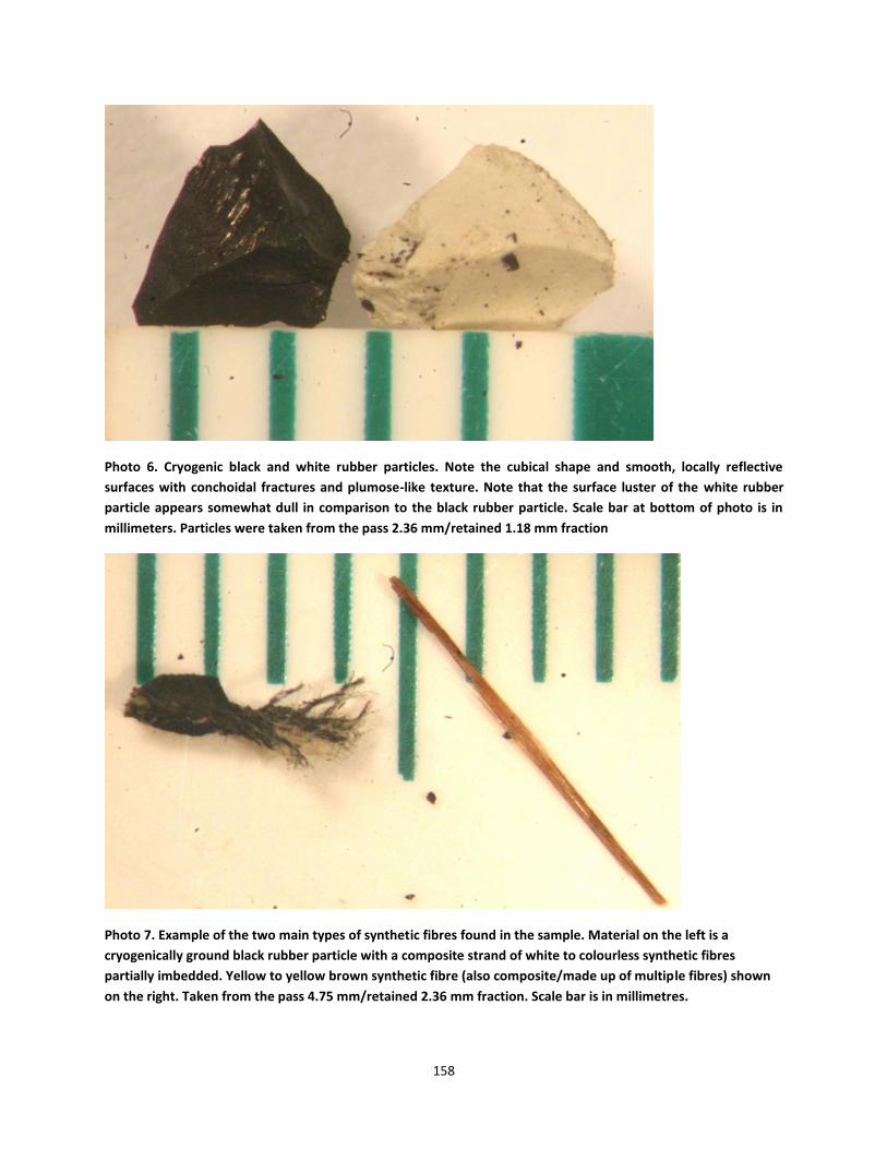
158
Photo 6. Cryogenic black and white rubber particles. Note the cubical shape and smooth, locally reflective
surfaces with conchoidal fractures and plumose-like texture. Note that the surface luster of the white rubber
particle appears somewhat dull in comparison to the black rubber particle. Scale bar at bottom of photo is in
millimeters. Particles were taken from the pass 2.36 mm/retained 1.18 mm fraction
Photo 7. Example of the two main types of synthetic fibres found in the sample. Material on the left is a
cryogenically ground black rubber particle with a composite strand of white to colourless synthetic fibres
partially imbedded. Yellow to yellow brown synthetic fibre (also composite/made up of multiple fibres) shown
on the right. Taken from the pass 4.75 mm/retained 2.36 mm fraction. Scale bar is in millimetres.

159
Photo 8. Material taken from the passing 300 µm/retained 150 µm fraction of the crumb rubber to illustrate the
bunching or clustering of the synthetic fibres during sieving of the material. Scale bar at bottom of photo is in
millimetres.
Photo 9. Fibres picked from cluster shown on the right side of photo 13 as viewed under the petrographic
microscope in plane polarized light. Fibres are mounted on a glass slide in 1.5150 refractive index fluid. Note the
individual rubber particle (R) in the upper central part of photo as well as other accumulations of rubber (R)
adhered to the fibres. Colourless synthetic fibres (F) and chopped brown synthetic (BF) are also shown in this
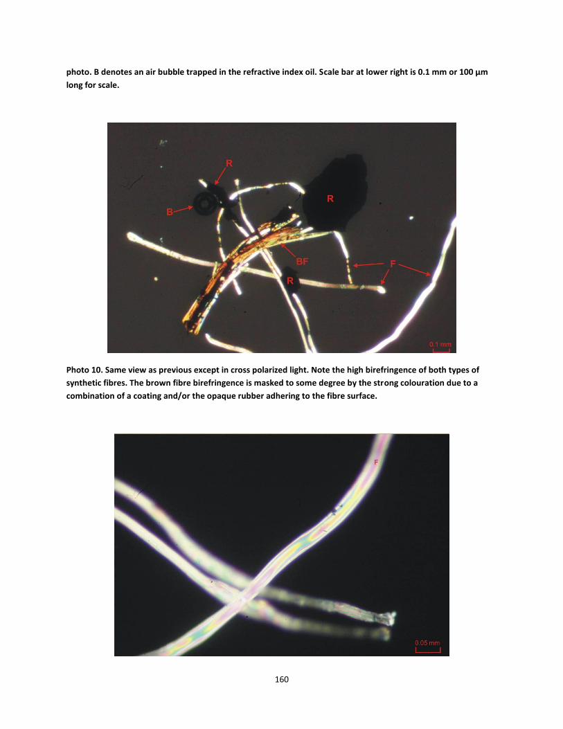
160
photo. B denotes an air bubble trapped in the refractive index oil. Scale bar at lower right is 0.1 mm or 100 µm
long for scale.
Photo 10. Same view as previous except in cross polarized light. Note the high birefringence of both types of
synthetic fibres. The brown fibre birefringence is masked to some degree by the strong colouration due to a
combination of a coating and/or the opaque rubber adhering to the fibre surface.

161
Photo 11. Increased magnification view of colourless transparent fibres (F) from previous photo showing the
high second to fourth order birefringence. Scale bar at lower right is 0.05 mm or 50 µm long for scale.
Photo 12. Single fiber found in the pass 4.75 mm/retained 2.36 mm fraction of its kind. Black, opaque, relatively
non-flexible fiber.

162
Photo 13. Left to right: ambient ground rubber particle, ambient ground particle with colourless synthetic fibers
adhered to and/or embedded in the particle (middle), and cryogenic grind particle with the same type of
synthetic fibers partially embedded in the particle (right). Photo was taken under the stereomicroscope. Scale
bar at bottom of photo is in millimeters. Material was taken from the pass 2.36 mm/retained 1.18 mm fraction.
Photo 14. Material from the pass 75 µm fraction mounted on a glass slide in 1.5150 refractive index fluid as
viewed under the petrographic microscope in plane polarized light (PPL). Mineral grains of quartz (Q) and
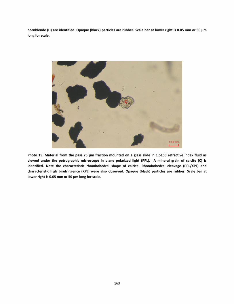
163
hornblende (H) are identified. Opaque (black) particles are rubber. Scale bar at lower right is 0.05 mm or 50 µm
long for scale.
Photo 15. Material from the pass 75 µm fraction mounted on a glass slide in 1.5150 refractive index fluid as
viewed under the petrographic microscope in plane polarized light (PPL). A mineral grain of calcite (C) is
identified. Note the characteristic rhombohedral shape of calcite. Rhombohedral cleavage (PPL/XPL) and
characteristic high birefringence (XPL) were also observed. Opaque (black) particles are rubber. Scale bar at
lower right is 0.05 mm or 50 µm long for scale.

164
Photo 16. Material from the pass 75 µm fraction mounted on a glass slide in 1.5150 refractive index fluid as
viewed under the petrographic microscope in plane polarized light (PPL). A mineral grain of quartz (Q) is
identified near centre of photo. Also note the presence of other (smaller) mineral grains toward the upper left
part of photo which is mostly quartz. Also note the presence of a synthetic (type 1) fiber toward the lower right
part of photo as well as the presence of numerous opaque (black) rubber particles. Scale bar at lower right is
0.05 mm or 50 µm long for scale.

165
Photo 17. Glass slide prepared of material from the pass 2.36 mm/retained 1.18 mm portion of the crumb
rubber sample for point counting.
Photo 18. Glass slide prepared of material from the pass 1.18 mm/retained 600µm portion of the crumb rubber
sample for point counting.

166
Photo 19. Glass slide prepared of material from the pass 600µm/retained 300 µm portion of the crumb rubber
sample for point counting.
Photo 20. Glass slide prepared of material from the pass 300µm/retained 150 µm portion of the crumb rubber
sample for point counting.
Photo 21. Glass slide prepared of material from the pass 150 µm/retained 75 µm portion of the crumb rubber sample for point counting.