Embed Size (px)
Citation preview
Technical Data Sheet
Rubidium™ RF/Microwave Signal Generator
MG36221A9 kHz to 20 GHz
MG36241A9 kHz to 43.5 GHz
Rubidium Signal Generator Technical Data
2 of 24 PN: 11410-00928 Rev. A MG362x1A TDS
Introduction The Rubidium™ MG362x1A is a microwave signal generator offering industry's lowest phase noise, best in class harmonics and spurious, excellent frequency stability, high output power, upgradability, reliability, and service. Our signal generators are configurable for a broad range of applications from R&D to manufacturing and depot repair. The Rubidium MG362x1A signal generator product line is built to deliver outstanding signal purity and frequency stability across a broad frequency range of 9 kHz to 43.5 GHz, even at high output power levels.
The Rubidium MG362x1A provides two tiers of phase noise performance as options in addition to the standard tier. The Low Phase Noise option delivers improved close-in phase noise than the standard Rubidium along with better frequency stability. The Ultra Low Phase Noise Option provides improved phase noise at higher offsets. For CW only applications between 2 GHz to 20 GHz, Rubidium provides even lower phase noise than the Ultra Low Phase Noise option, by another 3 dB on a separate RF output port at the back panel.
The low noise RF/microwave signal generator Rubidium MG362x1A offers atomic clock frequency stability with an internal rubidium frequency reference option. Alternatively, customers can also get exceptional frequency stability by locking an internal oven controlled crystal oscillator (OCXO) reference to an external GNSS/GPS signal. The exceptional frequency stability coupled with low phase noise performance makes the Rubidium MG362x1A the ideal choice for many measurement applications.
The Rubidium MG362x1A modulation capabilities include AM, FM, phase, and pulse to address simple to complex signal simulation requirements. It offers comprehensive pulse generation capabilities for testing pulse radar systems. It also supports Anritsu’s True-RMS and CW USB power sensors.
Anritsu provides you a total solution including proven reliability and standard 3 year warranty plus pre-sale and post-sale support that is the best in the industry.
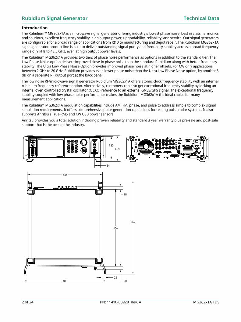
133 153
34
446
18
483 26
552
456
20
Technical Data Rubidium Signal Generator
MG362x1A TDS PN: 11410-00928 Rev. A 3 of 24
Table of Contents Definitions. . . . . . . . . . . . . . . . . . . . . . . . . . . . . . . . . . . . . . . . . . . . . . . . . . . . . . . . . . . . . . . . . . . . . . . . . . . . . . . . . . . . . 4Frequency . . . . . . . . . . . . . . . . . . . . . . . . . . . . . . . . . . . . . . . . . . . . . . . . . . . . . . . . . . . . . . . . . . . . . . . . . . . . . . . . . . . . . 5
Internal Time Base . . . . . . . . . . . . . . . . . . . . . . . . . . . . . . . . . . . . . . . . . . . . . . . . . . . . . . . . . . . . . . . . . . . . . . . . . . 5Internal Reference Output . . . . . . . . . . . . . . . . . . . . . . . . . . . . . . . . . . . . . . . . . . . . . . . . . . . . . . . . . . . . . . . . . . . . 5External Reference Input . . . . . . . . . . . . . . . . . . . . . . . . . . . . . . . . . . . . . . . . . . . . . . . . . . . . . . . . . . . . . . . . . . . . . 5Electronic Frequency Control. . . . . . . . . . . . . . . . . . . . . . . . . . . . . . . . . . . . . . . . . . . . . . . . . . . . . . . . . . . . . . . . . . 5
Signal Purity . . . . . . . . . . . . . . . . . . . . . . . . . . . . . . . . . . . . . . . . . . . . . . . . . . . . . . . . . . . . . . . . . . . . . . . . . . . . . . . . . . . 6Harmonic and Harmonic Related . . . . . . . . . . . . . . . . . . . . . . . . . . . . . . . . . . . . . . . . . . . . . . . . . . . . . . . . . . . . . . 6Non-Harmonic . . . . . . . . . . . . . . . . . . . . . . . . . . . . . . . . . . . . . . . . . . . . . . . . . . . . . . . . . . . . . . . . . . . . . . . . . . . . . . 6Power Line and Fan Rotation Spurious Emissions . . . . . . . . . . . . . . . . . . . . . . . . . . . . . . . . . . . . . . . . . . . . . . . . 6Residual FM . . . . . . . . . . . . . . . . . . . . . . . . . . . . . . . . . . . . . . . . . . . . . . . . . . . . . . . . . . . . . . . . . . . . . . . . . . . . . . . . 6Single–Sideband Phase Noise . . . . . . . . . . . . . . . . . . . . . . . . . . . . . . . . . . . . . . . . . . . . . . . . . . . . . . . . . . . . . . . . . 7Premium Phase Noise, CW (Option 23) . . . . . . . . . . . . . . . . . . . . . . . . . . . . . . . . . . . . . . . . . . . . . . . . . . . . . . . .11Output Power Unleveled . . . . . . . . . . . . . . . . . . . . . . . . . . . . . . . . . . . . . . . . . . . . . . . . . . . . . . . . . . . . . . . . . . . .11Harmonics. . . . . . . . . . . . . . . . . . . . . . . . . . . . . . . . . . . . . . . . . . . . . . . . . . . . . . . . . . . . . . . . . . . . . . . . . . . . . . . . .11Spurious . . . . . . . . . . . . . . . . . . . . . . . . . . . . . . . . . . . . . . . . . . . . . . . . . . . . . . . . . . . . . . . . . . . . . . . . . . . . . . . . . .11
Output Power. . . . . . . . . . . . . . . . . . . . . . . . . . . . . . . . . . . . . . . . . . . . . . . . . . . . . . . . . . . . . . . . . . . . . . . . . . . . . . . . .12Maximum Leveled Output Power . . . . . . . . . . . . . . . . . . . . . . . . . . . . . . . . . . . . . . . . . . . . . . . . . . . . . . . . . . . . .12Accuracy and Flatness. . . . . . . . . . . . . . . . . . . . . . . . . . . . . . . . . . . . . . . . . . . . . . . . . . . . . . . . . . . . . . . . . . . . . . .14Minimum Settable Output Power . . . . . . . . . . . . . . . . . . . . . . . . . . . . . . . . . . . . . . . . . . . . . . . . . . . . . . . . . . . . .14Minimum Leveled Output Power . . . . . . . . . . . . . . . . . . . . . . . . . . . . . . . . . . . . . . . . . . . . . . . . . . . . . . . . . . . . .14Unleveled Output Power Range . . . . . . . . . . . . . . . . . . . . . . . . . . . . . . . . . . . . . . . . . . . . . . . . . . . . . . . . . . . . . .14Power Level Switching Time. . . . . . . . . . . . . . . . . . . . . . . . . . . . . . . . . . . . . . . . . . . . . . . . . . . . . . . . . . . . . . . . . .14Step Attenuator (Option 2) . . . . . . . . . . . . . . . . . . . . . . . . . . . . . . . . . . . . . . . . . . . . . . . . . . . . . . . . . . . . . . . . . . .14General Output Power Specifications. . . . . . . . . . . . . . . . . . . . . . . . . . . . . . . . . . . . . . . . . . . . . . . . . . . . . . . . . .14
Power Modes . . . . . . . . . . . . . . . . . . . . . . . . . . . . . . . . . . . . . . . . . . . . . . . . . . . . . . . . . . . . . . . . . . . . . . . . . . . . . . . . .14CW Power Sweep . . . . . . . . . . . . . . . . . . . . . . . . . . . . . . . . . . . . . . . . . . . . . . . . . . . . . . . . . . . . . . . . . . . . . . . . . . .14
Frequency Modes . . . . . . . . . . . . . . . . . . . . . . . . . . . . . . . . . . . . . . . . . . . . . . . . . . . . . . . . . . . . . . . . . . . . . . . . . . . . .15Phase-Locked Step Sweep . . . . . . . . . . . . . . . . . . . . . . . . . . . . . . . . . . . . . . . . . . . . . . . . . . . . . . . . . . . . . . . . . . .15Frequency Switching Time . . . . . . . . . . . . . . . . . . . . . . . . . . . . . . . . . . . . . . . . . . . . . . . . . . . . . . . . . . . . . . . . . . .15List Sweep . . . . . . . . . . . . . . . . . . . . . . . . . . . . . . . . . . . . . . . . . . . . . . . . . . . . . . . . . . . . . . . . . . . . . . . . . . . . . . . . .15Sweep Triggering. . . . . . . . . . . . . . . . . . . . . . . . . . . . . . . . . . . . . . . . . . . . . . . . . . . . . . . . . . . . . . . . . . . . . . . . . . .15
AM, FM, ΦM, and Pulse Modulation, Internal/External . . . . . . . . . . . . . . . . . . . . . . . . . . . . . . . . . . . . . . . . . . . . . .16Amplitude Modulation (Option 12) . . . . . . . . . . . . . . . . . . . . . . . . . . . . . . . . . . . . . . . . . . . . . . . . . . . . . . . . . . . .16Frequency/Phase Modulation (Option 12) . . . . . . . . . . . . . . . . . . . . . . . . . . . . . . . . . . . . . . . . . . . . . . . . . . . . . .16External FM/Phase Mod Input . . . . . . . . . . . . . . . . . . . . . . . . . . . . . . . . . . . . . . . . . . . . . . . . . . . . . . . . . . . . . . . .18Pulse Modulation (Option 26) . . . . . . . . . . . . . . . . . . . . . . . . . . . . . . . . . . . . . . . . . . . . . . . . . . . . . . . . . . . . . . . .18Modulation Hardware (Option 27) . . . . . . . . . . . . . . . . . . . . . . . . . . . . . . . . . . . . . . . . . . . . . . . . . . . . . . . . . . . .19
General . . . . . . . . . . . . . . . . . . . . . . . . . . . . . . . . . . . . . . . . . . . . . . . . . . . . . . . . . . . . . . . . . . . . . . . . . . . . . . . . . . . . . .20Remote Operation. . . . . . . . . . . . . . . . . . . . . . . . . . . . . . . . . . . . . . . . . . . . . . . . . . . . . . . . . . . . . . . . . . . . . . . . . .20Environmental (MIL-PRF-28800F, class 3) . . . . . . . . . . . . . . . . . . . . . . . . . . . . . . . . . . . . . . . . . . . . . . . . . . . . . .20Regulatory Compliance. . . . . . . . . . . . . . . . . . . . . . . . . . . . . . . . . . . . . . . . . . . . . . . . . . . . . . . . . . . . . . . . . . . . . .20
Rear Panel. . . . . . . . . . . . . . . . . . . . . . . . . . . . . . . . . . . . . . . . . . . . . . . . . . . . . . . . . . . . . . . . . . . . . . . . . . . . . . . . . . . .21Rear Panel Connectors . . . . . . . . . . . . . . . . . . . . . . . . . . . . . . . . . . . . . . . . . . . . . . . . . . . . . . . . . . . . . . . . . . . . . .21
Ordering Information . . . . . . . . . . . . . . . . . . . . . . . . . . . . . . . . . . . . . . . . . . . . . . . . . . . . . . . . . . . . . . . . . . . . . . . . . .22MG36221A Options . . . . . . . . . . . . . . . . . . . . . . . . . . . . . . . . . . . . . . . . . . . . . . . . . . . . . . . . . . . . . . . . . . . . . . . . .22MG36241A Options . . . . . . . . . . . . . . . . . . . . . . . . . . . . . . . . . . . . . . . . . . . . . . . . . . . . . . . . . . . . . . . . . . . . . . . . .22Standard Accessories . . . . . . . . . . . . . . . . . . . . . . . . . . . . . . . . . . . . . . . . . . . . . . . . . . . . . . . . . . . . . . . . . . . . . . .22Accessories . . . . . . . . . . . . . . . . . . . . . . . . . . . . . . . . . . . . . . . . . . . . . . . . . . . . . . . . . . . . . . . . . . . . . . . . . . . . . . . .22Upgrades . . . . . . . . . . . . . . . . . . . . . . . . . . . . . . . . . . . . . . . . . . . . . . . . . . . . . . . . . . . . . . . . . . . . . . . . . . . . . . . . .23MG362x1A Option Configuration Matrix . . . . . . . . . . . . . . . . . . . . . . . . . . . . . . . . . . . . . . . . . . . . . . . . . . . . . . .23
Rubidium Signal Generator Specifications
4 of 24 PN: 11410-00928 Rev. A MG362x1A TDS
Definitions Supplemental characteristics, denoted as typical, measured, or nominal, provide additional (non-warranted) information, helpful in the application of the product.
Warranted Performance All specifications and characteristics apply under the stated conditions below, unless otherwise stated:• After 30 minutes of warm-up time, where the instrument is left in the on state.• Over the 25 °C ± 5 °C temperature range.
Typical Performance Typical specifications in parenthesis () describe performance that will be met by a minimum of 80% of all products. They do not include guard bands and are not warranted.
Measured Performance Represents characteristic performance not warranted, but most likely to occur. Nominal Performance Represents representative performance not warranted or statistically derived from measurements, but by
design.Calibration Cycle Recommended calibration cycle is 2 years from the date of shipment (Standard Warranty).
All specifications subject to change without notice. For the most current data sheet, please visit the Anritsuweb site: www.anritsu.com
Technical Data Rubidium Signal Generator
MG362x1A TDS PN: 11410-00928 Rev. A 5 of 24
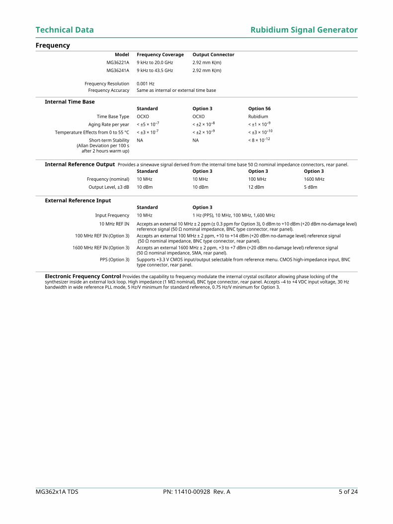
Frequency
Frequency Resolution 0.001 HzFrequency Accuracy Same as internal or external time base
Internal Time Base
Internal Reference Output Provides a sinewave signal derived from the internal time base 50 Ω nominal impedance connectors, rear panel.
External Reference Input
10 MHz REF IN Accepts an external 10 MHz ± 2 ppm (± 0.3 ppm for Option 3), 0 dBm to +10 dBm (+20 dBm no-damage level) reference signal (50 Ω nominal impedance, BNC type connector, rear panel).
100 MHz REF IN (Option 3) Accepts an external 100 MHz ± 2 ppm, +10 to +14 dBm (+20 dBm no-damage level) reference signal (50 Ω nominal impedance, BNC type connector, rear panel).
1600 MHz REF IN (Option 3) Accepts an external 1600 MHz ± 2 ppm, +3 to +7 dBm (+20 dBm no-damage level) reference signal (50 Ω nominal impedance, SMA, rear panel).
PPS (Option 3) Supports +3.3 V CMOS input/output selectable from reference menu. CMOS high-impedance input, BNC type connector, rear panel.
Electronic Frequency Control Provides the capability to frequency modulate the internal crystal oscillator allowing phase locking of the synthesizer inside an external lock loop. High impedance (1 MΩ nominal), BNC type connector, rear panel. Accepts –4 to +4 VDC input voltage, 30 Hz bandwidth in wide reference PLL mode, 5 Hz/V minimum for standard reference, 0.75 Hz/V minimum for Option 3.
Model Frequency Coverage Output Connector
MG36221A 9 kHz to 20.0 GHz 2.92 mm K(m)
MG36241A 9 kHz to 43.5 GHz 2.92 mm K(m)
Standard Option 3 Option 56
Time Base Type OCXO OCXO Rubidium
Aging Rate per year < ±5 × 10⁻⁷ < ±2 × 10⁻⁸ < ±1 × 10⁻⁹
Temperature Effects from 0 to 55 °C < ±3 × 10⁻⁷ < ±2 × 10⁻⁹ < ±3 × 10⁻¹⁰
Short-term Stability(Allan Deviation per 100 s
after 2 hours warm up)
NA NA < 8 × 10–12
Standard Option 3 Option 3 Option 3
Frequency (nominal) 10 MHz 10 MHz 100 MHz 1600 MHz
Output Level, ±3 dB 10 dBm 10 dBm 12 dBm 5 dBm
Standard Option 3
Input Frequency 10 MHz 1 Hz (PPS), 10 MHz, 100 MHz, 1,600 MHz
Rubidium Signal Generator Technical Data
6 of 24 PN: 11410-00928 Rev. A MG362x1A TDS
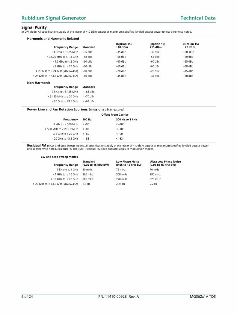
Signal Purity In CW Mode. All specifications apply at the lesser of +10 dBm output or maximum specified leveled output power unless otherwise noted.
Harmonic and Harmonic Related
Non-Harmonic
Power Line and Fan Rotation Spurious Emissions dBc (measured)
Residual FM In CW and Step Sweep Modes, all specifications apply at the lesser of +10 dBm output or maximum specified leveled output power unless otherwise noted. Residual FM (Hz RMS) (Residual FM spec does not apply to modulation modes)
Frequency Range Standard(Option 15)+10 dBm
(Option 15)+15 dBm
(Option 15)+20 dBm
9 kHz to 31.25 MHz –35 dBc –35 dBc –30 dBc –30 dBc
> 31.25 MHz to 1.3 GHz –58 dBc –58 dBc –55 dBc –50 dBc
> 1.3 GHz to 2 GHz –60 dBc –60 dBc –60 dBc –55 dBc
≥ 2 GHz to 20 GHz –60 dBc –60 dBc –60 dBc –58 dBc
> 20 GHz to 24 GHz (MG36241A) –60 dBc –20 dBc –20 dBc –15 dBc
> 24 GHz to 43.5 GHz (MG36241A) –60 dBc –35 dBc –35 dBc –30 dBc
Frequency Range Standard
9 kHz to 31.25 MHz < –65 dBc
> 31.25 MHz to 20 GHz < –70 dBc
> 20 GHz to 43.5 GHz < –63 dBc
Offset From Carrier
Frequency 300 Hz 300 Hz to 1 kHz
9 kHz to 500 MHz < –90 < –100
> 500 MHz to 2 GHz MHz < –80 < –100
≥ 2 GHz to 20 GHz < –60 < –90
> 20 GHz to 43.5 GHz < –53 < –83
CW and Step Sweep modes
Frequency RangeStandard (0.05 to 15 kHz BW)
Low Phase Noise (0.05 to 15 kHz BW)
Ultra Low Phase Noise(0.05 to 15 kHz BW)
9 kHz to 1 GHz 80 mHz 75 mHz 70 mHz
> 1 GHz to 10 GHz 360 mHz 350 mHz 280 mHz
> 10 GHz to 20 GHz 800 mHz 770 mHz 620 mHz
> 20 GHz to 43.5 GHz (MG36241A) 2.5 Hz 2.25 Hz 2.2 Hz
Technical Data Rubidium Signal Generator
MG362x1A TDS PN: 11410-00928 Rev. A 7 of 24
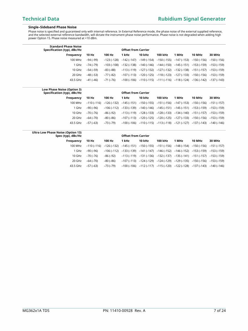
Single–Sideband Phase Noise Phase noise is specified and guaranteed only with internal reference. In External Reference mode, the phase noise of the external supplied reference, and the selected external reference bandwidth, will dictate the instrument phase noise performance. Phase noise is not degraded when adding high power Option 15. Phase noise measured at +10 dBm.
Standard Phase NoiseSpecification (typ), dBc/Hz Offset from Carrier
Frequency 10 Hz 100 Hz 1 kHz 10 kHz 100 kHz 1 MHz 10 MHz 30 MHz
100 MHz –94 (–99) –123 (–128) –142 (–147) –149 (–154) –150 (–155) –147 (–153) –150 (–156) –150 (–156)
1 GHz –74 (–79) –103 (–108) –132 (–138) –140 (–146) –144 (–150) –145 (–151) –153 (–159) –153 (–159)
10 GHz –54 (–59) –83 (–88) –113 (–119) –127 (–132) –127 (–132) –132 (–138) –151 (–157) –153 (–159)
20 GHz –48 (–53) –77 (–82) –107 (–113) –120 (–125) –118 (–123) –127 (–133) –150 (–156) –153 (–159)
43.5 GHz –41 (–46) –71 (–76) –100 (–106) –110 (–115) –111 (–116) –118 (–124) –136 (–142) –137 (–143)
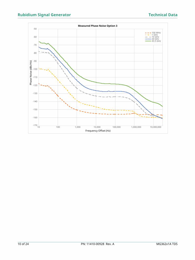
Low Phase Noise (Option 3)Specification (typ), dBc/Hz Offset from Carrier
Frequency 10 Hz 100 Hz 1 kHz 10 kHz 100 kHz 1 MHz 10 MHz 30 MHz
100 MHz –110 (–116) –126 (–132) –145 (–151) –150 (–155) –151 (–156) –147 (–153) –150 (–156) –151 (–157)
1 GHz –90 (–96) –106 (–112) –133 (–139) –140 (–146) –145 (–151) –145 (–151) –153 (–159) –153 (–159)
10 GHz –70 (–76) –86 (–92) –113 (–119) –128 (–133) –128 (–133) –134 (–140) –151 (–157) –153 (–159)
20 GHz –64 (–70) –80 (–86) –107 (–113) –120 (–125) –120 (–125) –127 (–133) –150 (–156) –153 (–159)
43.5 GHz –57 (–63) –73 (–79) –100 (–106) –110 (–115) –113 (–118) –121 (–127) –137 (–143) –140 (–146)
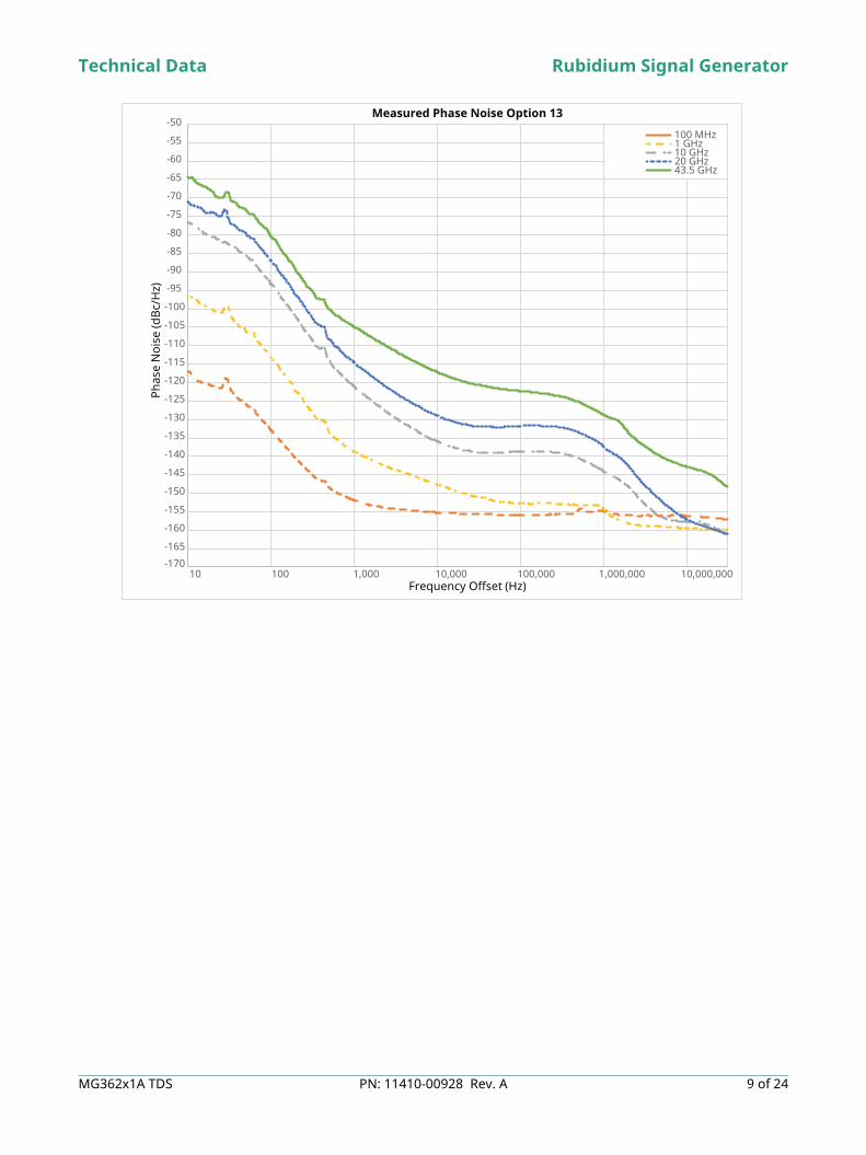
Ultra Low Phase Noise (Option 13)Spec (typ), dBc/Hz Offset from Carrier
Frequency 10 Hz 100 Hz 1 kHz 10 kHz 100 kHz 1 MHz 10 MHz 30 MHz
100 MHz –110 (–116) –126 (–132) –145 (–151) –150 (–155) –151 (–156) –148 (–154) –150 (–156) –151 (–157)
1 GHz –90 (–96) –106 (–112) –133 (–139) –141 (–147) –146 (–152) –146 (–152) –153 (–159) –153 (–159)
10 GHz –70 (–76) –86 (–92) –113 (–119) –131 (–136) –132 (–137) –135 (–141) –151 (–157) –153 (–159)
20 GHz –64 (–70) –80 (–86) –107 (–113) –124 (–129) –124 (–129) –129 (–135) –150 (–156) –153 (–159)
43.5 GHz –57 (–63) –73 (–79) –100 (–106) –112 (–117) –115 (–120) –122 (–128) –137 (–143) –140 (–146)
Rubidium Signal Generator Technical Data
8 of 24 PN: 11410-00928 Rev. A MG362x1A TDS
-170
-160
-150
-140
-130
-120
-110
-100
-90
-80
-70
-60
-50
10 100 1,000 10,000 100,000 1,000,000 10,000,000
Phas
e N
oise
(dBc
/Hz)
Frequency Offset (Hz)
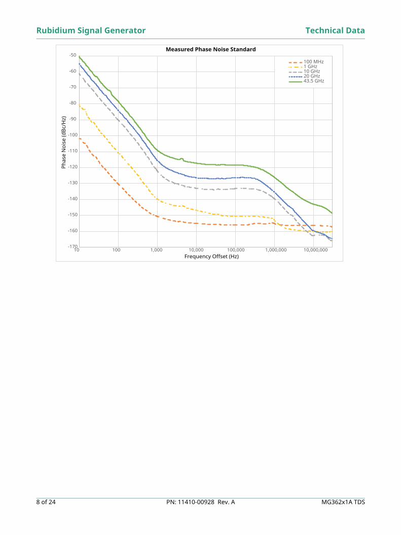
Measured Phase Noise Standard
100 MHz1 GHz10 GHz20 GHz43.5 GHz
Technical Data Rubidium Signal Generator
MG362x1A TDS PN: 11410-00928 Rev. A 9 of 24
-170
-165
-160
-155
-150
-145
-140
-135
-130
-125
-120
-115
-110
-105
-100
-95
-90
-85
-80
-75
-70
-65
-60
-55
-50
10 100 1,000 10,000 100,000 1,000,000 10,000,000
Phas
e N
oise
(dBc
/Hz)
Frequency Offset (Hz)
Measured Phase Noise Option 13
100 MHz 1 GHz 10 GHz 20 GHz 43.5 GHz
Rubidium Signal Generator Technical Data
10 of 24 PN: 11410-00928 Rev. A MG362x1A TDS
-170
-160
-150
-140
-130
-120
-110
-100
-90
-80
-70
-60
-50
10 100 1,000 10,000 100,000 1,000,000 10,000,000
Phas
e N
oise
(dBc
/Hz)
Frequency Offset (Hz)
Measured Phase Noise Option 3
100 MHz1 GHz10 GHz20 GHz43.5 GHz
Technical Data Rubidium Signal Generator
MG362x1A TDS PN: 11410-00928 Rev. A 11 of 24
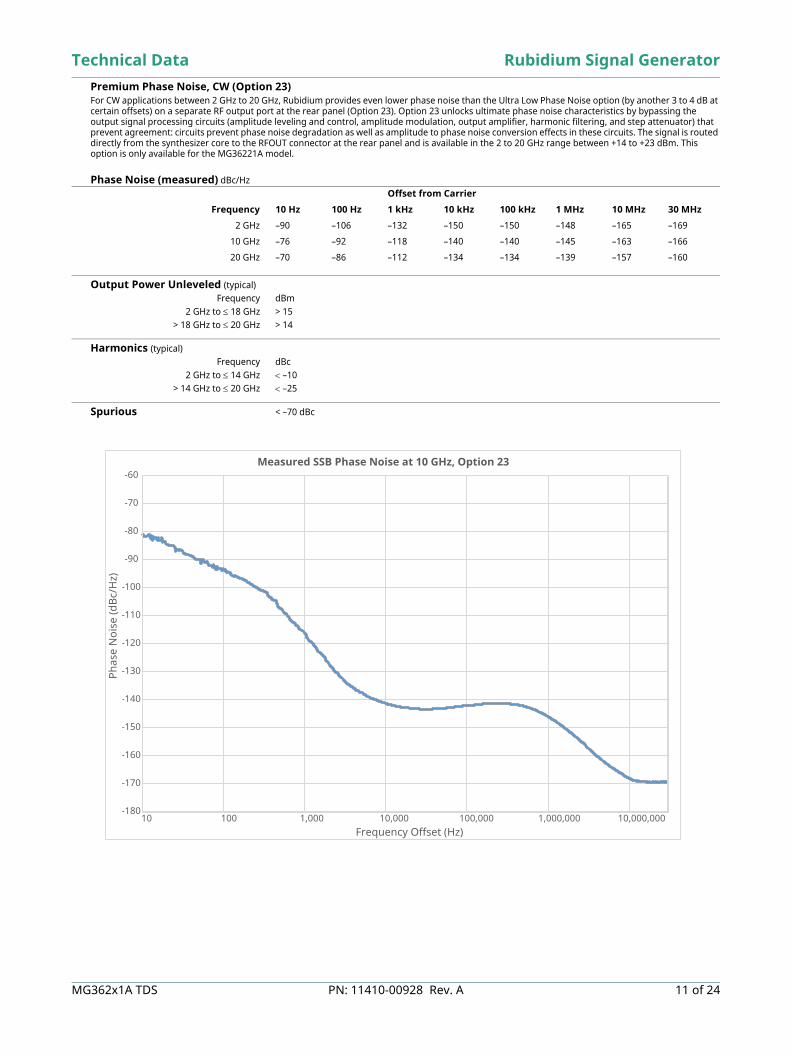
Premium Phase Noise, CW (Option 23) For CW applications between 2 GHz to 20 GHz, Rubidium provides even lower phase noise than the Ultra Low Phase Noise option (by another 3 to 4 dB at certain offsets) on a separate RF output port at the rear panel (Option 23). Option 23 unlocks ultimate phase noise characteristics by bypassing the output signal processing circuits (amplitude leveling and control, amplitude modulation, output amplifier, harmonic filtering, and step attenuator) that prevent agreement: circuits prevent phase noise degradation as well as amplitude to phase noise conversion effects in these circuits. The signal is routed directly from the synthesizer core to the RFOUT connector at the rear panel and is available in the 2 to 20 GHz range between +14 to +23 dBm. This option is only available for the MG36221A model. Phase Noise (measured) dBc/Hz
Output Power Unleveled (typical)Frequency dBm
2 GHz to 18 GHz > 15> 18 GHz to 20 GHz > 14
Harmonics (typical)Frequency dBc
2 GHz to 14 GHz –10> 14 GHz to 20 GHz –25
Spurious < –70 dBc
Offset from Carrier
Frequency 10 Hz 100 Hz 1 kHz 10 kHz 100 kHz 1 MHz 10 MHz 30 MHz
2 GHz –90 –106 –132 –150 –150 –148 –165 –169
10 GHz –76 –92 –118 –140 –140 –145 –163 –166
20 GHz –70 –86 –112 –134 –134 –139 –157 –160
-180
-170
-160
-150
-140
-130
-120
-110
-100
-90
-80
-70
-60
10 100 1,000 10,000 100,000 1,000,000 10,000,000Frequency Offset (Hz)
Measured SSB Phase Noise at 10 GHz, Option 23
Phas
e N
oise
(dBc
/Hz)
Rubidium Signal Generator Technical Data
12 of 24 PN: 11410-00928 Rev. A MG362x1A TDS
Output Power
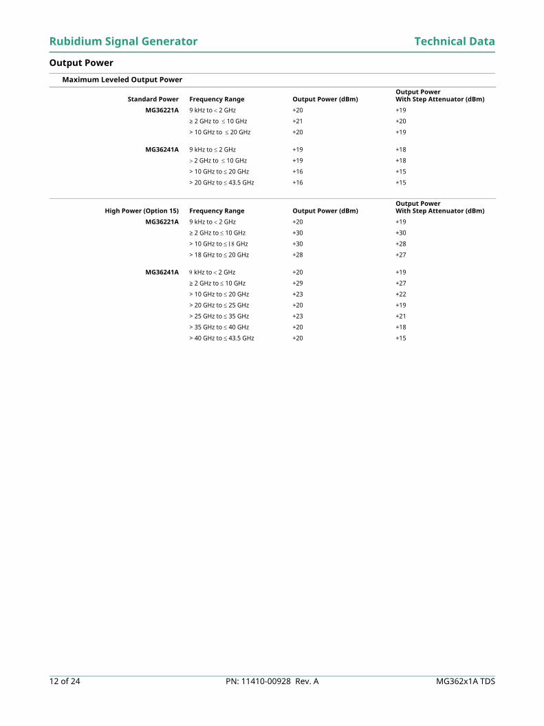
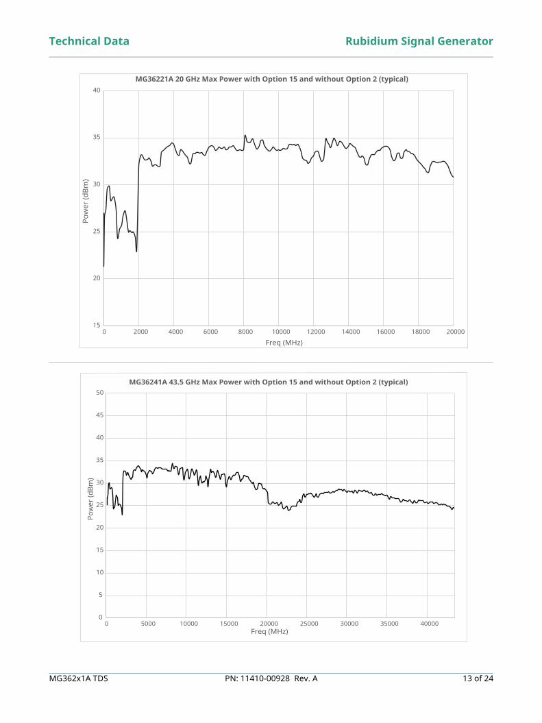
Maximum Leveled Output Power
Standard Power Frequency Range Output Power (dBm) Output Power With Step Attenuator (dBm)
MG36221A 9 kHz to 2 GHz +20 +19
≥ 2 GHz to 10 GHz +21 +20
> 10 GHz to 20 GHz +20 +19
MG36241A 9 kHz to 2 GHz +19 +18
2 GHz to 10 GHz +19 +18
> 10 GHz to 20 GHz +16 +15
> 20 GHz to 43.5 GHz +16 +15
High Power (Option 15) Frequency Range Output Power (dBm) Output Power With Step Attenuator (dBm)
MG36221A 9 kHz to 2 GHz +20 +19
≥ 2 GHz to 10 GHz +30 +30
> 10 GHz to GHz +30 +28
> 18 GHz to 20 GHz +28 +27
MG36241A kHz to 2 GHz +20 +19
≥ 2 GHz to 10 GHz +29 +27
> 10 GHz to 20 GHz +23 +22
> 20 GHz to 25 GHz +20 +19
> 25 GHz to 35 GHz +23 +21
> 35 GHz to 40 GHz +20 +18
> 40 GHz to 43.5 GHz +20 +15
Technical Data Rubidium Signal Generator
MG362x1A TDS PN: 11410-00928 Rev. A 13 of 24
15
20
25
30
35
40
0 2000 4000 6000 8000 10000 12000 14000 16000 18000 20000
Pow
er (d
Bm)
Freq (MHz)
MG36221A 20 GHz Max Power with Option 15 and without Option 2 (typical)
0
5
10
15
20
25
30
35
40
45
50
0 5000 10000 15000 20000 25000 30000 35000 40000
Pow
er (d
Bm)
Freq (MHz)
MG36241A 43.5 GHz Max Power with Option 15 and without Option 2 (typical)
Rubidium Signal Generator Technical Data
14 of 24 PN: 11410-00928 Rev. A MG362x1A TDS
Accuracy and Flatness (Flatness is included within the accuracy specification.)
Minimum Settable Output Power Without an Attenuator –20 dBm
With an Attenuator –130 dBm
Minimum Leveled Output Power Without an Attenuator –15 dBm
With an Attenuator –120 dBm (–70 dBm from 9 kHz to 70 kHz)
Unleveled Output Power Range (typical)Without an Attenuator > 40 dB below max power
With an Attenuator > 130 dB below max power
Power Level Switching Time (to within specified accuracy)Without Change in Step Attenuator < 3 ms typical
With Change in Step Attenuator < 20 ms typical
Step Attenuator (Option 2) Adds a 10 dB/step attenuator110 dB range on models 43.5 GHz
General Output Power Specifications Output Units Output units selectable as either dBm, dBµV, and V. Selection of V assumes a 50 load. All data entry and
display are in the selected units.Output Power Resolution 0.01 dB or 0.000 001 V
Output Impedance 50 nominalOutput SWR (Internal Leveling) < 2.0 (typical)
Power Level Stability with Temperature ± 0.04 dB/°C Level Offset Offsets the displayed power level to establish a new reference level.
RF On/Off Toggles the RF output between an Off and On state. During the Off state, the RF oscillator is turned off. The On or Off state is indicated by an LED button located above the RF Output connector on the front panel.
RF On/Off Between Frequency Steps System menu selection of RF On or RF Off during frequency switching in CW, Step Sweep, and List Sweep modes.
RF On/Off During Retrace System menu selection of RF On or RF Off during retrace.Internal Leveling Power is leveled at the output connector in all modes.
.
Power Modes
CW Power Sweep Range Sweeps between any two power levels at a single CW frequency.
Operating Modes Step, ListTriggering Modes Auto, SingleTriggering Source Internal Free run, External (pos/neg) through BNC connector, Bus
Resolution 0.01 dB/step (Log) or 0.000 001 V (Linear)Accuracy Same as CW power accuracy
Log/Linear Sweep Power sweep selectable as either log or linear. Log sweep is in dB; linear sweep is in V.Sweep Shape Sawtooth
Step Size User-controlled, 0.01 dB (Log) or 0.000 001 V (Linear) to the full power range of the instrument.Step Dwell Time Variable from 10 us to 100 seconds. If the sweep crosses a step attenuator setting, there will be a sweep
dwell of approximately 20 ms to allow setting of the step attenuator.
Power Range Frequency Accuracy
Maximum Power to -90 dBm 9 kHz to 40 GHz ± 1 dB
Maximum Power to -90 dBm > 40 GHz to 43.5 GHz ± 1.4 dB
Technical Data Rubidium Signal Generator
MG362x1A TDS PN: 11410-00928 Rev. A 15 of 24
Frequency Modes
Phase-Locked Step Sweep Sweep Width Independently selected, 9 kHz to full range
Every frequency step in sweep range is phase-lockedAccuracy Same as internal or external time base
Linear/Log Sweep User-selectable linear or log sweepIn log sweep, step size logarithmically increases with frequency.
Steps User-selectable number of steps or the step sizeNumber of Steps Variable from 2 to 65535
Step Size 0.001Hz to the full frequency range of the instrumentIf the step size does not divide into the selected frequency range, the last step is truncated.
Resolution (Minimum Step Size) 0.001 HzSweep Mode Auto, Manual
Triggering Mode Auto, SingleTrigger Source Auto, Single, External, Manual
Dwell Time Per Step Variable from 10 µS to 100 S
Frequency Switching Time Switching time is from Unlocked indication to frequency settled to within < 1 kHz of final.
T, msec = T1 + abs [(F1 + K1)*N1 – (F2 + K2)*N2]*1 msec/GHz where:T1 = 5 msecF1 = RF output frequency, GHz, at beginning of the frequency stepF2 = RF output frequency, GHz, at end of the frequency stepKx = LO frequency, GHz, (internal to the DDC or HET downconverter) for given Fx.Nx = YIG frequency division ratio, per the chart below, for given Fx
List Sweep Manual, GPIB, or Ethernet control, or via the front panel, up to 10 tables with 4000 non-sequential frequency/power sets can be stored and then addressed as a phase-locked step sweep. All tables are stored in non-volatile memory. Only one table is exposed on the GUI.
Triggering Mode Auto, Single, External, Manual Trigger Source Internal free run, external (pos/neg) through BNC connector, timer, Bus
Rate (list mode switching) See Frequency Switching Time Sweep Range 9 kHz to full frequency range and amplitude range
Dwell Time 10 µs to 100 sMinimum Step Size 0.001 Hz
Sweep Triggering Sweep triggering is provided for Analog Frequency Sweep, Step Frequency Sweep, List Frequency Sweep, and CW Power Sweep.
Auto Triggers sweep automatically.External Triggers a sweep (pos/neg) through BNC connector, Bus.
Single Sweep Triggers, aborts, and resets a single sweep.Reset sweep may be selected to be at the top or bottom of the sweep.
Single Step Triggers each step of the sweep and waits for next trigger.
RF Output (GHz) YIG Divider (N) Downconverter LO, GHz (K)
> 40 to 43.5 0.25 0
> 20 to 40 0.5 0
2 to 20 1 0
> 1 to < 2 2 0
> 0.5 to 1 4 0
> 0.25 to 0.5 8 0
> 0.125 to 0.25 16 0
> 0.0625 to 0.125 32 0
> 0.03125 to 0.0625 64 0
0.000009 to 0.03125 8 0.3
Rubidium Signal Generator Technical Data
16 of 24 PN: 11410-00928 Rev. A MG362x1A TDS
AM, FM, ΦM, and Pulse Modulation, Internal/External Option 12 adds amplitude, frequency and phase modulation. Option 26 adds pulse modulation. Modulation can be driven internally or externally. Internal modulation requires Option 27. External modulation is driven via rear panel 50 ohms BNC connectors, one each for AM and FM/ΦM. External modulation can also be driven from 50 Ω BNC connectors on the front panel with Option 29. AM, FM, ΦM, and Pulse modulation types may be simultaneously enabled except FM with ΦM.
Amplitude Modulation (Option 12) All amplitude modulation specifications apply at 50 % depth, 1 kHz rate, sine wave, leveled ALC, with RF level set 6 dB below maximum specified leveled output power, unless otherwise noted.
AM Depth Linear: 0 % to 90 % (nominal) Log: 0 dB to 20 dB (nominal)
Accuracy ±5 % relative to readoutAM Bandwidth (3 dB) DC to > 50 kHz (nominal)Harmonic Distortion < 5 % at 1 kHz: (typical)
External AM Input Log AM or Linear AM inputRear-panel BNC (50 Ω input impedance)
Sensitivity Log AM: Continuously variable from 0 dB per volt to 25 dB per volt.Linear AM: Continuously variable from 0 % per volt to 100 % per volt.
Maximum Input ±1 VpkDamage Level ±5 V
Frequency/Phase Modulation (Option 12) In the table below, Nmod and Nrf are multipliers that affect FM deviation at the measured frequency.
Fout (MHz) Nmod Fout (MHz) Nrf
> 0.009 to ≤ 20 0.0625 ≥ 0.009 to ≤ 31.25 0.125
> 20 to ≤ 31.25 0.125 > 31.25 to ≤ 62.5 0.015625
> 31.25 to ≤ 40 0.0078125 > 62.5 to ≤ 125 0.03125
> 40 to ≤ 80 0.015625 > 125 to ≤ 250 0.0625
> 80 to ≤ 160 0.03125 >250 to ≤ 500 0.125
> 160 to ≤ 320 0.0625 > 500 to ≤ 1,000 0.25
> 320 to ≤ 640 0.125 > 1,000 to ≤ 2,000 0.5
> 640 to ≤ 1,280 0.25 > 1,000 to ≤ 2,000 0.5
> 1,280 to < 2,000 0.5 ≥ 2,000 to ≤ 20,000 1
≥ 2,000 to ≤ 2,560 0.5 > 20,000 to ≤ 40,000 2
> 2,560 to ≤ 5,120 1 > 40,000 to ≤ 43,500 4
> 5,120 to ≤ 10,240 1
> 10,240 to ≤ 20,000 1
> 20,000 to ≤ 40,000 2
> 40,000 to ≤ 43,500 4

Technical Data Rubidium Signal Generator
MG362x1A TDS PN: 11410-00928 Rev. A 17 of 24
Frequency Modulation
Parameter Modes Specifications
Conditions, Int or Ext @ 1V pk AC, 0V DC, DC HPF, sinewave, except as noted
Max Deviation Low Noise 10 MHz *Nmod (see Nmod table)
Rate = 1 kHz to lesser of (8 MHz or 0.03 *RF)RF ≥ 2 MHz
Wide (unlocked) 100 MHz *Nrf, typical (see Nrf table)
Rate = 10 HzRF > 31.25 MHz
Min Deviation Low Noise 640 Hz *Nmod, nominal (less if Ext FM < ±1V)
Rate = 1 kHz
Wide (unlocked) 3.2 kHz *Nrf, nominal, (less if Ext FM < ±1V)
Rate = 10 kHz
Deviation Accuracy Low Noise Internal: ±2 %, External: ±3 % of indication
Rate = 1 kHz, Deviation Setting =2 MHz *NmodRF > 2 MHz
External Sensitivity Low Noise (1.28 kHz/V to 20 MHz/V) *Nmod
Wide (unlocked) (3.2 kHz/V to 105 MHz/V) *Nmod
External Sensitivity Accuracy Low Noise 3 % nominal Rate = 1 kHz
Flatness vs. Modulation Rate Low Noise ± 1dB, typical 1 kHz to 1 MHz rate vs. 1 kHz, for RF > 31.25 MHzDeviation setting = 2 MHz *Nmod
3 dB Bandwidth Low Noise DC to 10 MHz vs. 1 kHz rate, DC couple, Deviation setting = 2 MHz *NmodFor RF > 250 MHz
Wide (unlocked) DC to > 500 Hz, nominal vs. 10 Hz rate,Deviation setting = 10 MHz *Nrf
Highpass Filter DC, 63 Hz, 1 kHz, nominal
Harmonic distortion (THD) Low Noise 1 % Rate = 1 kHz, 50 kHz. Deviation = 300 kHz, 50 kHzRF ≤ 160 MHz, RF > 1 MHz
Incidental AM Low Noise ≤ 0.3 % rms 50 Hz to 15 kHz integration BW, Rate = 1 kHz, Dev = 50 kHz
Residual FM Low Noise ≤ 3 kHz rms 50 Hz to 15 kHz integration BW, Rate = 1 kHz, Dev = 50 kHz
Rubidium Signal Generator Technical Data
18 of 24 PN: 11410-00928 Rev. A MG362x1A TDS
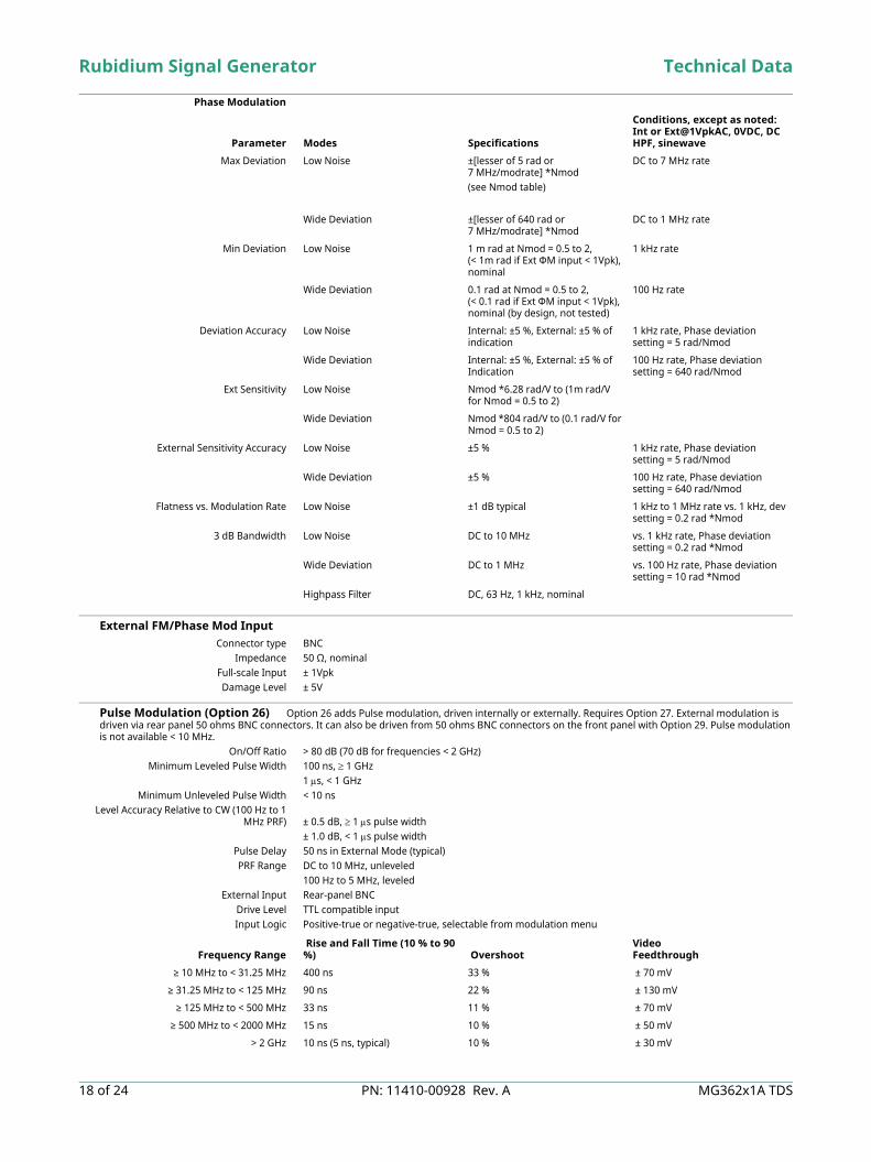
External FM/Phase Mod Input Connector type BNC
Impedance 50 Ω, nominalFull-scale Input ± 1VpkDamage Level ± 5V
Pulse Modulation (Option 26) Option 26 adds Pulse modulation, driven internally or externally. Requires Option 27. External modulation is driven via rear panel 50 ohms BNC connectors. It can also be driven from 50 ohms BNC connectors on the front panel with Option 29. Pulse modulation is not available < 10 MHz.
On/Off Ratio > 80 dB (70 dB for frequencies < 2 GHz)Minimum Leveled Pulse Width 100 ns, 1 GHz
1 s, < 1 GHzMinimum Unleveled Pulse Width < 10 ns
Level Accuracy Relative to CW (100 Hz to 1MHz PRF) ± 0.5 dB, 1 s pulse width
± 1.0 dB, < 1 s pulse width Pulse Delay 50 ns in External Mode (typical)PRF Range DC to 10 MHz, unleveled
100 Hz to 5 MHz, leveledExternal Input Rear-panel BNC
Drive Level TTL compatible inputInput Logic Positive-true or negative-true, selectable from modulation menu
Phase Modulation
Parameter Modes Specifications
Conditions, except as noted: Int or Ext@1VpkAC, 0VDC, DC HPF, sinewave
Max Deviation Low Noise ±[lesser of 5 rad or7 MHz/modrate] *Nmod(see Nmod table)
DC to 7 MHz rate
Wide Deviation ±[lesser of 640 rad or 7 MHz/modrate] *Nmod
DC to 1 MHz rate
Min Deviation Low Noise 1 m rad at Nmod = 0.5 to 2, (< 1m rad if Ext ΦM input < 1Vpk),nominal
1 kHz rate
Wide Deviation 0.1 rad at Nmod = 0.5 to 2, (< 0.1 rad if Ext ΦM input < 1Vpk),nominal (by design, not tested)
100 Hz rate
Deviation Accuracy Low Noise Internal: ±5 %, External: ±5 % of indication
1 kHz rate, Phase deviation setting = 5 rad/Nmod
Wide Deviation Internal: ±5 %, External: ±5 % of Indication
100 Hz rate, Phase deviation setting = 640 rad/Nmod
Ext Sensitivity Low Noise Nmod *6.28 rad/V to (1m rad/V for Nmod = 0.5 to 2)
Wide Deviation Nmod *804 rad/V to (0.1 rad/V for Nmod = 0.5 to 2)
External Sensitivity Accuracy Low Noise ±5 % 1 kHz rate, Phase deviation setting = 5 rad/Nmod
Wide Deviation ±5 % 100 Hz rate, Phase deviation setting = 640 rad/Nmod
Flatness vs. Modulation Rate Low Noise ±1 dB typical 1 kHz to 1 MHz rate vs. 1 kHz, dev setting = 0.2 rad *Nmod
3 dB Bandwidth Low Noise DC to 10 MHz vs. 1 kHz rate, Phase deviation setting = 0.2 rad *Nmod
Wide Deviation DC to 1 MHz vs. 100 Hz rate, Phase deviation setting = 10 rad *Nmod
Highpass Filter DC, 63 Hz, 1 kHz, nominal
Frequency Range Rise and Fall Time (10 % to 90 %) Overshoot
VideoFeedthrough
≥ 10 MHz to < 31.25 MHz 400 ns 33 % ± 70 mV
≥ 31.25 MHz to < 125 MHz 90 ns 22 % ± 130 mV
≥ 125 MHz to < 500 MHz 33 ns 11 % ± 70 mV
≥ 500 MHz to < 2000 MHz 15 ns 10 % ± 50 mV
> 2 GHz 10 ns (5 ns, typical) 10 % ± 30 mV
Technical Data Rubidium Signal Generator
MG362x1A TDS PN: 11410-00928 Rev. A 19 of 24
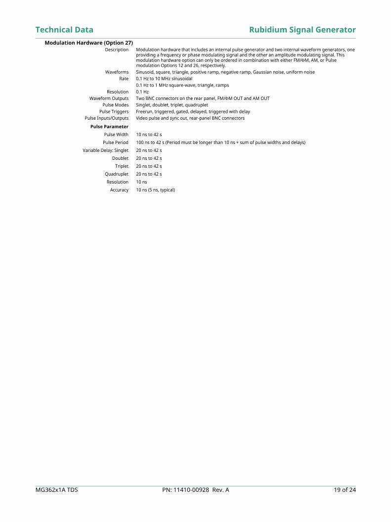
Modulation Hardware (Option 27) Description Modulation hardware that includes an internal pulse generator and two internal waveform generators, one
providing a frequency or phase modulating signal and the other an amplitude modulating signal. This modulation hardware option can only be ordered in combination with either FM/M, AM, or Pulse modulation Options 12 and 26, respectively.
Waveforms Sinusoid, square, triangle, positive ramp, negative ramp, Gaussian noise, uniform noiseRate 0.1 Hz to 10 MHz sinusoidal
0.1 Hz to 1 MHz square-wave, triangle, rampsResolution 0.1 Hz
Waveform Outputs Two BNC connectors on the rear panel, FM/M OUT and AM OUTPulse Modes Singlet, doublet, triplet, quadruplet
Pulse Triggers Freerun, triggered, gated, delayed, triggered with delayPulse Inputs/Outputs Video pulse and sync out, rear-panel BNC connectors
Pulse Parameter
Pulse Width 10 ns to 42 s
Pulse Period 100 ns to 42 s (Period must be longer than 10 ns + sum of pulse widths and delays)
Variable Delay: Singlet 20 ns to 42 s
Doublet 20 ns to 42 s
Triplet 20 ns to 42 s
Quadruplet 20 ns to 42 s
Resolution 10 ns
Accuracy 10 ns (5 ns, typical)
Rubidium Signal Generator Technical Data
20 of 24 PN: 11410-00928 Rev. A MG362x1A TDS
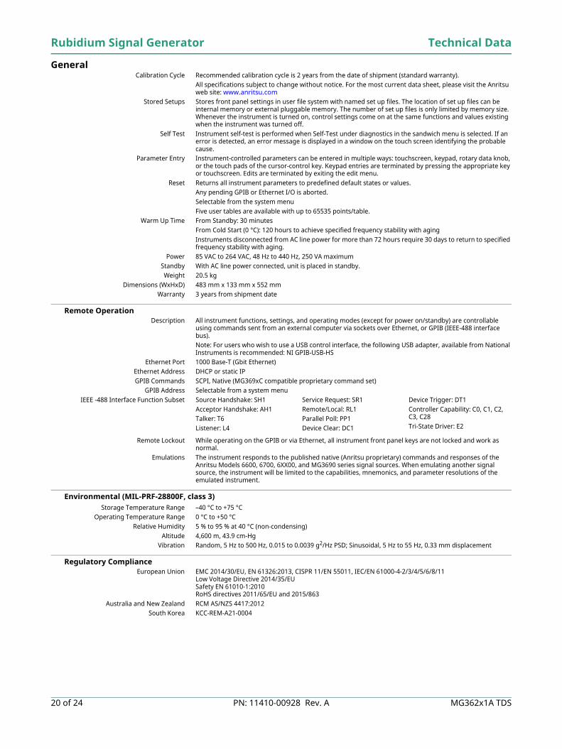
General Calibration Cycle Recommended calibration cycle is 2 years from the date of shipment (standard warranty).
All specifications subject to change without notice. For the most current data sheet, please visit the Anritsu web site: www.anritsu.com
Stored Setups Stores front panel settings in user file system with named set up files. The location of set up files can be internal memory or external pluggable memory. The number of set up files is only limited by memory size. Whenever the instrument is turned on, control settings come on at the same functions and values existing when the instrument was turned off.
Self Test Instrument self-test is performed when Self-Test under diagnostics in the sandwich menu is selected. If an error is detected, an error message is displayed in a window on the touch screen identifying the probable cause.
Parameter Entry Instrument-controlled parameters can be entered in multiple ways: touchscreen, keypad, rotary data knob, or the touch pads of the cursor-control key. Keypad entries are terminated by pressing the appropriate key or touchscreen. Edits are terminated by exiting the edit menu.
Reset Returns all instrument parameters to predefined default states or values.Any pending GPIB or Ethernet I/O is aborted. Selectable from the system menuFive user tables are available with up to 65535 points/table.
Warm Up Time From Standby: 30 minutesFrom Cold Start (0 °C): 120 hours to achieve specified frequency stability with agingInstruments disconnected from AC line power for more than 72 hours require 30 days to return to specified frequency stability with aging.
Power 85 VAC to 264 VAC, 48 Hz to 440 Hz, 250 VA maximumStandby With AC line power connected, unit is placed in standby.Weight 20.5 kg
Dimensions (WxHxD) 483 mm x 133 mm x 552 mm Warranty 3 years from shipment date
Remote Operation Description All instrument functions, settings, and operating modes (except for power on/standby) are controllable
using commands sent from an external computer via sockets over Ethernet, or GPIB (IEEE-488 interface bus).Note: For users who wish to use a USB control interface, the following USB adapter, available from National Instruments is recommended: NI GPIB-USB-HS
Ethernet Port 1000 Base-T (Gbit Ethernet)Ethernet Address DHCP or static IPGPIB Commands SCPI, Native (MG369xC compatible proprietary command set)
GPIB Address Selectable from a system menu
Remote Lockout While operating on the GPIB or via Ethernet, all instrument front panel keys are not locked and work as normal.
Emulations The instrument responds to the published native (Anritsu proprietary) commands and responses of the Anritsu Models 6600, 6700, 6XX00, and MG3690 series signal sources. When emulating another signal source, the instrument will be limited to the capabilities, mnemonics, and parameter resolutions of the emulated instrument.
Environmental (MIL-PRF-28800F, class 3) Storage Temperature Range –40 °C to +75 °C
Operating Temperature Range 0 °C to +50 °CRelative Humidity 5 % to 95 % at 40 °C (non-condensing)
Altitude 4,600 m, 43.9 cm-HgVibration Random, 5 Hz to 500 Hz, 0.015 to 0.0039 g2/Hz PSD; Sinusoidal, 5 Hz to 55 Hz, 0.33 mm displacement
Regulatory Compliance European Union EMC 2014/30/EU, EN 61326:2013, CISPR 11/EN 55011, IEC/EN 61000-4-2/3/4/5/6/8/11
Low Voltage Directive 2014/35/EU Safety EN 61010-1:2010 RoHS directives 2011/65/EU and 2015/863
Australia and New Zealand RCM AS/NZS 4417:2012 South Korea KCC-REM-A21-0004
IEEE -488 Interface Function Subset Source Handshake: SH1Acceptor Handshake: AH1Talker: T6Listener: L4
Service Request: SR1Remote/Local: RL1Parallel Poll: PP1Device Clear: DC1
Device Trigger: DT1Controller Capability: C0, C1, C2, C3, C28Tri-State Driver: E2
Technical Data Rubidium Signal Generator
MG362x1A TDS PN: 11410-00928 Rev. A 21 of 24
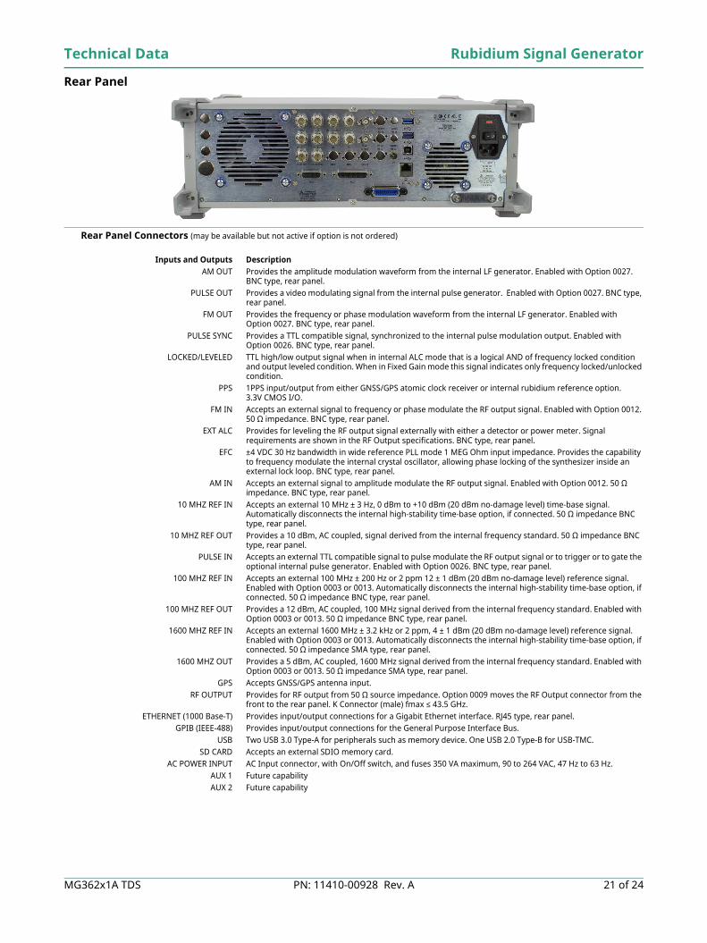
Rear Panel
Rear Panel Connectors (may be available but not active if option is not ordered)
Inputs and Outputs Description AM OUT Provides the amplitude modulation waveform from the internal LF generator. Enabled with Option 0027.
BNC type, rear panel.PULSE OUT Provides a video modulating signal from the internal pulse generator. Enabled with Option 0027. BNC type,
rear panel. FM OUT Provides the frequency or phase modulation waveform from the internal LF generator. Enabled with
Option 0027. BNC type, rear panel. PULSE SYNC Provides a TTL compatible signal, synchronized to the internal pulse modulation output. Enabled with
Option 0026. BNC type, rear panel. LOCKED/LEVELED TTL high/low output signal when in internal ALC mode that is a logical AND of frequency locked condition
and output leveled condition. When in Fixed Gain mode this signal indicates only frequency locked/unlocked condition.
PPS 1PPS input/output from either GNSS/GPS atomic clock receiver or internal rubidium reference option. 3.3V CMOS I/O.
FM IN Accepts an external signal to frequency or phase modulate the RF output signal. Enabled with Option 0012. 50 Ω impedance. BNC type, rear panel.
EXT ALC Provides for leveling the RF output signal externally with either a detector or power meter. Signal requirements are shown in the RF Output specifications. BNC type, rear panel.
EFC ±4 VDC 30 Hz bandwidth in wide reference PLL mode 1 MEG Ohm input impedance. Provides the capability to frequency modulate the internal crystal oscillator, allowing phase locking of the synthesizer inside an external lock loop. BNC type, rear panel.
AM IN Accepts an external signal to amplitude modulate the RF output signal. Enabled with Option 0012. 50 Ω impedance. BNC type, rear panel.
10 MHZ REF IN Accepts an external 10 MHz ± 3 Hz, 0 dBm to +10 dBm (20 dBm no-damage level) time-base signal. Automatically disconnects the internal high-stability time-base option, if connected. 50 Ω impedance BNC type, rear panel.
10 MHZ REF OUT Provides a 10 dBm, AC coupled, signal derived from the internal frequency standard. 50 Ω impedance BNC type, rear panel.
PULSE IN Accepts an external TTL compatible signal to pulse modulate the RF output signal or to trigger or to gate the optional internal pulse generator. Enabled with Option 0026. BNC type, rear panel.
100 MHZ REF IN Accepts an external 100 MHz ± 200 Hz or 2 ppm 12 ± 1 dBm (20 dBm no-damage level) reference signal. Enabled with Option 0003 or 0013. Automatically disconnects the internal high-stability time-base option, if connected. 50 Ω impedance BNC type, rear panel.
100 MHZ REF OUT Provides a 12 dBm, AC coupled, 100 MHz signal derived from the internal frequency standard. Enabled with Option 0003 or 0013. 50 Ω impedance BNC type, rear panel.
1600 MHZ REF IN Accepts an external 1600 MHz ± 3.2 kHz or 2 ppm, 4 ± 1 dBm (20 dBm no-damage level) reference signal. Enabled with Option 0003 or 0013. Automatically disconnects the internal high-stability time-base option, if connected. 50 Ω impedance SMA type, rear panel.
1600 MHZ OUT Provides a 5 dBm, AC coupled, 1600 MHz signal derived from the internal frequency standard. Enabled with Option 0003 or 0013. 50 Ω impedance SMA type, rear panel.
GPS Accepts GNSS/GPS antenna input.RF OUTPUT Provides for RF output from 50 Ω source impedance. Option 0009 moves the RF Output connector from the
front to the rear panel. K Connector (male) fmax ≤ 43.5 GHz. ETHERNET (1000 Base-T) Provides input/output connections for a Gigabit Ethernet interface. RJ45 type, rear panel.
GPIB (IEEE-488) Provides input/output connections for the General Purpose Interface Bus. USB Two USB 3.0 Type-A for peripherals such as memory device. One USB 2.0 Type-B for USB-TMC.
SD CARD Accepts an external SDIO memory card.AC POWER INPUT AC Input connector, with On/Off switch, and fuses 350 VA maximum, 90 to 264 VAC, 47 Hz to 63 Hz.
AUX 1 Future capabilityAUX 2 Future capability
Rubidium Signal Generator Technical Data
22 of 24 PN: 11410-00928 Rev. A MG362x1A TDS
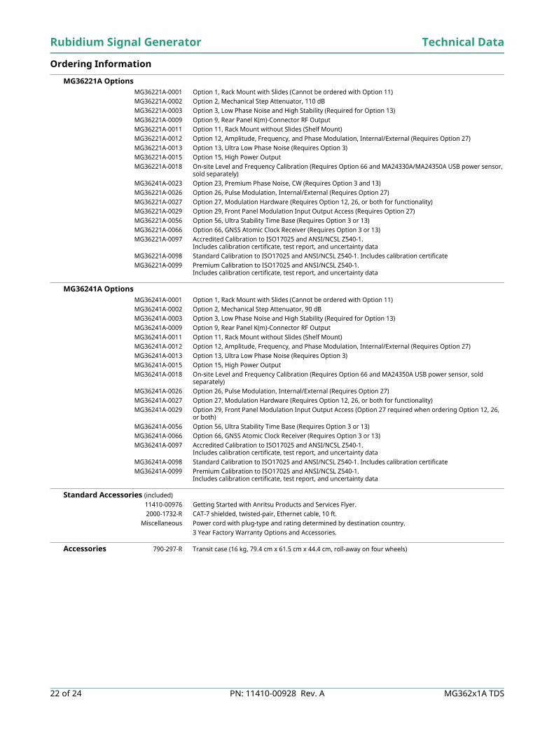
Ordering Information
MG36221A Options MG36221A-0001 Option 1, Rack Mount with Slides (Cannot be ordered with Option 11)MG36221A-0002 Option 2, Mechanical Step Attenuator, 110 dBMG36221A-0003 Option 3, Low Phase Noise and High Stability (Required for Option 13)MG36221A-0009 Option 9, Rear Panel K(m)-Connector RF OutputMG36221A-0011 Option 11, Rack Mount without Slides (Shelf Mount)MG36221A-0012 Option 12, Amplitude, Frequency, and Phase Modulation, Internal/External (Requires Option 27)MG36221A-0013 Option 13, Ultra Low Phase Noise (Requires Option 3)MG36221A-0015 Option 15, High Power OutputMG36221A-0018 On-site Level and Frequency Calibration (Requires Option 66 and MA24330A/MA24350A USB power sensor,
sold separately) MG36241A-0023 Option 23, Premium Phase Noise, CW (Requires Option 3 and 13)MG36221A-0026 Option 26, Pulse Modulation, Internal/External (Requires Option 27)MG36221A-0027 Option 27, Modulation Hardware (Requires Option 12, 26, or both for functionality)MG36221A-0029 Option 29, Front Panel Modulation Input Output Access (Requires Option 27)MG36221A-0056 Option 56, Ultra Stability Time Base (Requires Option 3 or 13)MG36221A-0066 Option 66, GNSS Atomic Clock Receiver (Requires Option 3 or 13)MG36221A-0097 Accredited Calibration to ISO17025 and ANSI/NCSL Z540-1.
Includes calibration certificate, test report, and uncertainty dataMG36221A-0098 Standard Calibration to ISO17025 and ANSI/NCSL Z540-1. Includes calibration certificateMG36221A-0099 Premium Calibration to ISO17025 and ANSI/NCSL Z540-1.
Includes calibration certificate, test report, and uncertainty data
MG36241A Options MG36241A-0001 Option 1, Rack Mount with Slides (Cannot be ordered with Option 11) MG36241A-0002 Option 2, Mechanical Step Attenuator, 90 dBMG36241A-0003 Option 3, Low Phase Noise and High Stability (Required for Option 13)MG36241A-0009 Option 9, Rear Panel K(m)-Connector RF OutputMG36241A-0011 Option 11, Rack Mount without Slides (Shelf Mount)MG36241A-0012 Option 12, Amplitude, Frequency, and Phase Modulation, Internal/External (Requires Option 27)MG36241A-0013 Option 13, Ultra Low Phase Noise (Requires Option 3)MG36241A-0015 Option 15, High Power OutputMG36241A-0018 On-site Level and Frequency Calibration (Requires Option 66 and MA24350A USB power sensor, sold
separately)MG36241A-0026 Option 26, Pulse Modulation, Internal/External (Requires Option 27)MG36241A-0027 Option 27, Modulation Hardware (Requires Option 12, 26, or both for functionality)MG36241A-0029 Option 29, Front Panel Modulation Input Output Access (Option 27 required when ordering Option 12, 26,
or both)MG36241A-0056 Option 56, Ultra Stability Time Base (Requires Option 3 or 13)MG36241A-0066 Option 66, GNSS Atomic Clock Receiver (Requires Option 3 or 13)MG36241A-0097 Accredited Calibration to ISO17025 and ANSI/NCSL Z540-1.
Includes calibration certificate, test report, and uncertainty dataMG36241A-0098 Standard Calibration to ISO17025 and ANSI/NCSL Z540-1. Includes calibration certificateMG36241A-0099 Premium Calibration to ISO17025 and ANSI/NCSL Z540-1.
Includes calibration certificate, test report, and uncertainty data
Standard Accessories (included)11410-00976 Getting Started with Anritsu Products and Services Flyer.2000-1732-R CAT-7 shielded, twisted-pair, Ethernet cable, 10 ft.
Miscellaneous Power cord with plug-type and rating determined by destination country.3 Year Factory Warranty Options and Accessories.
Accessories 790-297-R Transit case (16 kg, 79.4 cm x 61.5 cm x 44.4 cm, roll-away on four wheels)
Technical Data Rubidium Signal Generator
MG362x1A TDS PN: 11410-00928 Rev. A 23 of 24
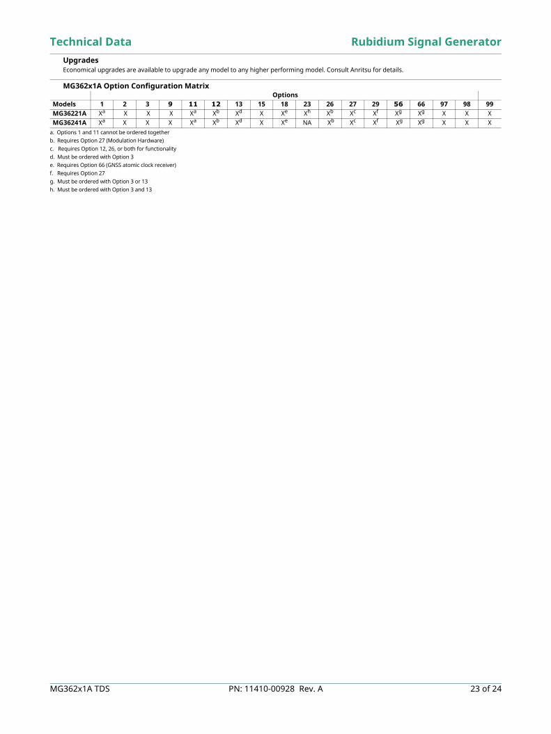
Upgrades Economical upgrades are available to upgrade any model to any higher performing model. Consult Anritsu for details.
MG362x1A Option Configuration Matrix Options
Models 1 2 3 9 11 12 13 15 18 23 26 27 29 56 66 97 98 99MG36221A Xa
a. Options 1 and 11 cannot be ordered together
X X X Xa Xb
b. Requires Option 27 (Modulation Hardware)c. Requires Option 12, 26, or both for functionalityd. Must be ordered with Option 3e. Requires Option 66 (GNSS atomic clock receiver)f. Requires Option 27 g. Must be ordered with Option 3 or 13h. Must be ordered with Option 3 and 13
Xd X Xe Xh Xb Xc Xf Xg Xg X X XMG36241A Xa X X X Xa Xb Xd X Xe NA Xb Xc Xf Xg Xg X X X

MG362x1A TDS, PN: 11410-00928, Rev. ACopyright November 2021, Anritsu Company, USA. All Rights Reserved.
® Anritsu All trademarks are registered trademarks of their respective companies.Anritsu utilizes recycled paper and environmentally conscious inks and toner.
Data subject to change without notice.For the most recent specifications, visit: www.anritsu.com.2424 of 24
Training at AnritsuAnritsu has designed courses to help you stay up to date with technologies important to your job. For available training courses, visit: www.anritsu.com/training
• United StatesAnritsu Americas Sales Company450 Century Parkway, Suite 190, Allen, TX 75013, U.S.A.Phone: +1-800-Anritsu (1-800-267-4878)
• CanadaAnritsu Electronics Ltd.700 Silver Seven Road, Suite 120, Kanata, Ontario K2V 1C3, CanadaPhone: +1-613-591-2003Fax: +1-613-591-1006
• BrazilAnritsu Eletronica Ltda.Praça Amadeu Amaral, 27 - 1 Andar01327-010 - Bela Vista - Sao Paulo - SP, BrazilPhone: +55-11-3283-2511Fax: +55-11-3288-6940
• MexicoAnritsu Company, S.A. de C.V.Blvd Miguel de Cervantes Saavedra #169 Piso 1, Col. Granada, Mexico, Ciudad de Mexico,11520, MEXICOPhone: +52-55-4169-7104
• United KingdomAnritsu EMEA Ltd.200 Capability Green, Luton, Bedfordshire, LU1 3LU, U.K.Phone: +44-1582-433200Fax: +44-1582-731303
• FranceAnritsu S.A.12 avenue du Québec, Immeuble Goyave,91140 VILLEBON SUR YVETTE, FrancePhone: +33-1-60-92-15-50
• GermanyAnritsu GmbHNemetschek Haus, Konrad-Zuse-Platz 1,81829 München, GermanyPhone: +49-89-442308-0Fax: +49-89-442308-55
• ItalyAnritsu S.r.l.Spaces Eur Arte, Viale dell’Arte 25, 00144 Roma, ItalyPhone: +39-6-509-9711
• SwedenAnritsu ABKistagången 20 B, 2 tr, 164 40 Kista, SwedenPhone: +46-8-534-707-00
• FinlandAnritsu ABTechnopolis Aviapolis, Teknobulevardi 3-5 (D208.5.),FI-01530 Vantaa, FinlandPhone: +358-20-741-8100
• DenmarkAnritsu A/Sc/o Regus Winghouse, Ørestads Boulevard 73, 4th floor, 2300 Copenhagen S, DenmarkPhone: +45-7211-2200
• RussiaAnritsu EMEA Ltd.Representation Office in RussiaTverskaya str. 16/2, bld. 1, 7th floor,Moscow 125009, RussiaPhone: +7-495-363-1694Fax: +7-495-935-8962
• SpainAnritsu EMEA Ltd.Representation Office in SpainPaseo de la Castellana, 141. Planta 5, Edificio Cuzco IV28046, Madrid, SpainPhone: +34-91-572-6761
• AustriaAnritsu EMEA GmbHAm Belvedere 10, A-1100 Vienna, AustriaPhone: +43-(0)1-717-28-710
• United Arab EmiratesAnritsu EMEA Ltd.Anritsu A/SOffice No. 164, Building 17, Dubai Internet CityP. O. Box – 501901, Dubai, United Arab EmiratesPhone: +971-4-3758479
• IndiaAnritsu India Private Limited6th Floor, Indiqube ETA, No.38/4, Adjacent to EMC2, Doddanekundi, Outer Ring Road, Bengaluru – 560048, IndiaPhone: +91-80-6728-1300Fax: +91-80-6728-1301
• SingaporeAnritsu Pte. Ltd.11 Chang Charn Road, #04-01, Shriro HouseSingapore 159640Phone: +65-6282-2400Fax: +65-6282-2533
• VietnamAnritsu Company Limited16th Floor, Peakview Tower, 36 Hoang Cau Street, O Cho Dua Ward, Dong Da District, Hanoi, VietnamPhone: +84-24-3201-2730
• P.R. China (Shanghai)Anritsu (China) Co., Ltd.Room 2701-2705, Tower A, New CaohejingInternational Business Center No. 391 Gui Ping RoadShanghai, 200233, P.R. ChinaPhone: +86-21-6237-0898Fax: +86-21-6237-0899
• P.R. China (Hong Kong)Anritsu Company Ltd.Unit 1006-7, 10/F., Greenfield Tower, Concordia Plaza,No. 1 Science Museum Road, Tsim Sha Tsui East, Kowloon, Hong Kong, P.R. ChinaPhone: +852-2301-4980Fax: +852-2301-3545
• JapanAnritsu Corporation8-5, Tamura-cho, Atsugi-shi, Kanagawa, 243-0016 JapanPhone: +81-46-296-6509Fax: +81-46-225-8352
• South KoreaAnritsu Corporation, Ltd.5FL, 235 Pangyoyeok-ro, Bundang-gu, Seongnam-si,Gyeonggi-do 13494, South KoreaPhone: +82-31-696-7750Fax: +82-31-696-7751
• AustraliaAnritsu Pty. Ltd.Unit 20, 21-35 Ricketts Road,Mount Waverley, Victoria 3149, AustraliaPhone: +61-3-9558-8177Fax: +61-3-9558-8255
• TaiwanAnritsu Company Inc.7F, No. 316, Sec. 1, NeiHu Rd., Taipei 114, TaiwanPhone: +886-2-8751-1816Fax: +886-2-8751-1817
List Revision Date: 20210610