Embed Size (px)
Citation preview
Rui Zhu
G. L. Huang1
e-mail: [email protected]
Department of Applied Science,
University of Arkansas at Little Rock,
2801 S University Avenue,
Little Rock, AR 72204-1099;
Department of System Engineering,
University of Arkansas at Little Rock,
2801 S University Avenue,
Little Rock, AR 72204-1099
Hargsoon Yoon1
e-mail: [email protected]
Courtney S. Smith
Department of Engineering,
Norfolk State University,
700 Park Avenue,
Norfolk, VA 23504
Vijay K. VaradanDepartment of Electrical Engineering,
University of Arkansas,
700 Research Center Boulevard,
Fayetteville, AR 72701;
Department of Neurosurgery,
College of Medicine,
Pennsylvania State Hershey Medical Center,
500 University Drive,
Hershey, PA 17033
Biomechanical Strain Analysisat the Interface of Brain andNanowire Electrodes on aNeural ProbeThe viability of neural probes with microelectrodes for neural recording and stimulationin the brain is important for the development of neuroprosthetic devices. Verticallyaligned nanowire microelectrode arrays can significantly enhance the capabilities ofneuroprosthetic devices. However, when they are implanted into the brain, micromotionand mechanical stress around the neural probe may cause tissue damage and reactiveimmune response, which may degrade recording signals from neurons. In this research, afinite-element model of the nanowire microelectrode and brain tissue was developed. Arigid body method was provided, and the simulation efficiency was significantlyincreased. The interface between the microelectrode and brain tissue was modeled bycontact elements. Brain micromotion was mimicked by applying a displacement load tothe electrode and fixing the boundaries of the brain region. It was observed that the verti-cally aligned nanostructures on the electrode of the neural probe do increase the cellularsheath area. The strain field distributions under various physical coupling cases at theinterface were analyzed along with different loading effects on the neural electrode.[DOI: 10.1115/1.4005484]
1 Introduction
The use of neural sensing devices is essential for longitudinallyand sensitively monitoring neuronal activities in mechanisticstudies of neurological and behavioral disorders, understandingneuronal network circuitry, as well as developing quantifiableindicators in preclinical studies of disease progression and treat-ment efficacy [1–3]. Ideal neural electrodes should have highcharging capacity and charge injection efficiency together withlong-term reliability for chronic implantation in brain tissue [4,5].In previous research, we have developed nanotechnology-enabledneural electrodes, which are small enough to sense localized unitcell spikes and dopamine concentration levels [6,7]. Even withincreased sensing efficiency, the function and longevity of neuralelectrodes is limited by adverse tissue reaction and immuneresponse upon implantation and micromotion in the brain [8]. Inparticular, the brain micromotion can induce strain in the areaaround neural probes, which in turn induces cellular sheath forma-tion. As shown in Fig. 1, brain motion ranging from a few tens tofew hundreds of microns arises from many different sources suchas physiological internal motion (respiration and cardiac pulses)and external motion (spontaneous head movements and externalimpact) [9,10]. The relative motion and mechanical disturbancesby rigid neural probes could generate mechanical stresses and
strains on the brain tissue adjacent to the electrode [11]. It isbelieved that compression, expansion, and even tearing of theneural cells trigger immune response and form compact sheathlayers, eventually isolating the probe function from neural cellsaround it [12].
Due to limited methods in which to analyze the microenviron-ment, little research has been done on the mechanical analysis onthe neural probe and brain tissue interface. Previous studies onlocalized strain around the probe tip and electrodes induced by de-formation of brain or static force on the probe have been limitedfor the conventional Michigan probe electrode type designs, aswell [13,14]. In this study, a finite-element model analysis isextended to the nanowire electrode–brain tissue interface in orderto understand the effects from vertically aligned nanostructures. Itis anticipated that the analysis of the strain field distribution undernanoscale interface conditions and different loading effectsapplied on the neural electrode may provide useful information,which can enhance the biocompatibility and longevity of neuralsensing in the brain.
2 Methods
2.1 Model. In this study, we assume that the neural probe isimplanted in the brain. Because of the small dimensions of theimplanted microelectrode, the brain tissue around the microelec-trode is considered to be homogeneous. In the simulation, themodel consists of two regions representing the brain tissue and theelectrode. The brain tissue can be modeled as a soft isotropic
1Corresponding authors.Manuscript received May 6, 2011; final manuscript received June 30, 2011;
published online January 9, 2012. Assoc. Editor: Linfeng Chen.
Journal of Nanotechnology in Engineering and Medicine AUGUST 2011, Vol. 2 / 031001-1Copyright VC 2011 by ASME
Downloaded 06 Feb 2012 to 139.78.12.97. Redistribution subject to ASME license or copyright; see http://www.asme.org/terms/Terms_Use.cfm
elastic material [15–17]. The Young’s modulus and Poisson’s ra-tio used for the brain tissue are 15 kPa and 0.499, respectively[18,19]. Because the strain effects are expected to be localizednear the electrode, the geometric representation of the brain islimited to the region surrounding the electrode. The boundaries ofthe brain model are defined to have sufficient distances from themicroelectrode to avoid the disruption of the strain field. For con-ventional neural probe electrodes, such as the Michigan electrode,the neural probe electrode is modeled as an elastic material withvery high bulk modulus in comparison with the brain tissue. Theneural probe shank, which is the component inserted into the tis-sue, has a thickness around 10 lm, a width around 100 lm, and alength within a few millimeters in our simulation. Due to thesharpened region near the tip of the neural probe shank, the meshdensity in that region needs to be refined, and a huge number ofelements will be generated. In this study, vertically aligned nano-wires are integrated into the neural probe design developed in ourprevious research [6,20,21]. Due to the tiny diameter of the nano-wire (�100 nm), the required mesh density in the nanowire areawill generate too many elements to run the simulation effectivelyin a university research lab environment. In order to overcomethe problem, a rigid body method is developed to dramaticallyreduce the number of elements in the simulation. Since the elastic
modulus of both nanowires and neural probe are very high com-pared to that of the brain tissue, they can be considered as rigidbodies, and the deformations within the nanowire area and neuralprobe can be ignored during the brain micromotion.
2.2 Elements and Meshing. The brain tissue area is meshedusing 3D 10-node tetrahedral structural solid element-SOLID92(ANASYS v11.0). Manual mesh is used to better control the meshdensity, which varies in different parts of the brain tissue area, inorder to increase the simulation efficiency. Low mesh density isapplied to the brain tissue area that is far away from the electrode,and the mesh density around the microelectrode is refined to focusthe simulation on the interface between the brain and the elec-trode. To preciously simulate the possible large deformation at theregions around the tip of the neural probe shank and the nanowireareas, further refinements to the mesh densities at those regionsare conducted.
2.3 Interface Conditions. In order to simulate variousdegrees of physical coupling at the interface between the neuralprobe shank and the brain tissue as well as the interface between
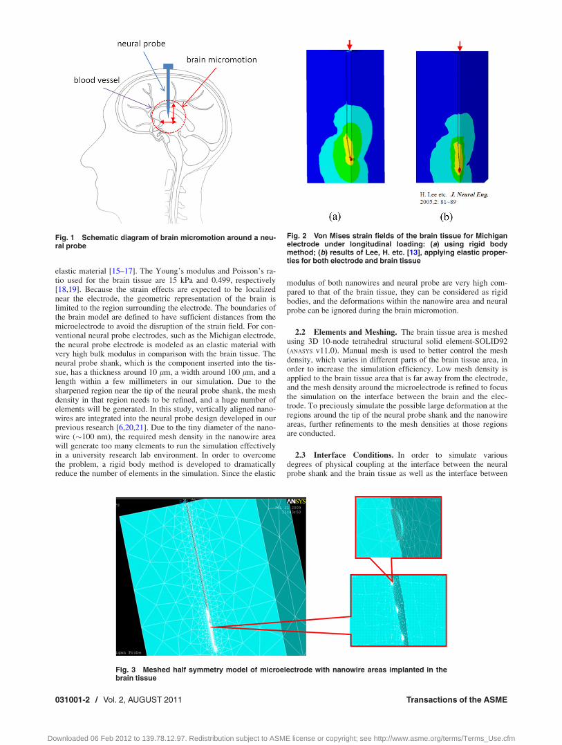
Fig. 2 Von Mises strain fields of the brain tissue for Michiganelectrode under longitudinal loading: (a) using rigid bodymethod; (b) results of Lee, H. etc. [13], applying elastic proper-ties for both electrode and brain tissue
Fig. 1 Schematic diagram of brain micromotion around a neu-ral probe
Fig. 3 Meshed half symmetry model of microelectrode with nanowire areas implanted in thebrain tissue
031001-2 / Vol. 2, AUGUST 2011 Transactions of the ASME
Downloaded 06 Feb 2012 to 139.78.12.97. Redistribution subject to ASME license or copyright; see http://www.asme.org/terms/Terms_Use.cfm
the nanowire area and the brain tissue, the friction coefficients varyin the contact finite element model. Friction coefficients of 0, 0.5,1, and 5 were used to simulate different degrees of physical cou-pling at the interface. The zero friction case represents no adhesion,which means the surface of the brain tissue and the electrodes canmove freely without interrupting each other along the tangent direc-tion at the interface. Friction coefficients of 0.5 and 1 represent the“slip” case in which the physical coupling between the electrodesand the brain increases as a higher friction coefficient is applied tothe interface. A friction coefficient of 5 is used to simulate thenearly “bonded” case. The results will be discussed in Sec. 3.
2.4 Load Application. In actuality, one end of the neuralprobe is fixed at the skull, and the brain moves, due to intracranialpressure changes. For modeling convenience, a reverse loadingcondition is applied. The equivalent loading mode in this model-ing can be chosen as micromotion, which is mimicked by apply-ing a displacement load to the electrodes and fixing the
boundaries of the brain region. In this study, “micromotion” isdefined as the movement of electrodes. The load was appliedalong different directions to simulate longitudinal and transversebrain micromotions.
3 Results
3.1 Michigan Electrode. In order to validate our rigid bodyassumption and evaluate the efficiency of the new method com-pared with the conventional one, a classic Michigan electrodeunder longitudinal loading is first studied using the rigid bodymethod. The result is compared with that of previous researchers’work as shown in Fig. 2 (zero friction case).
As shown in the Fig. 2, a quarter symmetric model is used forthe simulation based on the simple geometry of the Michiganelectrode. Von Mises strain field obtained by rigid body method[Fig. 2(a)] is very close to that simulated by the conventionalmethod [Fig. 2(b)]. However, due to the assumption that the
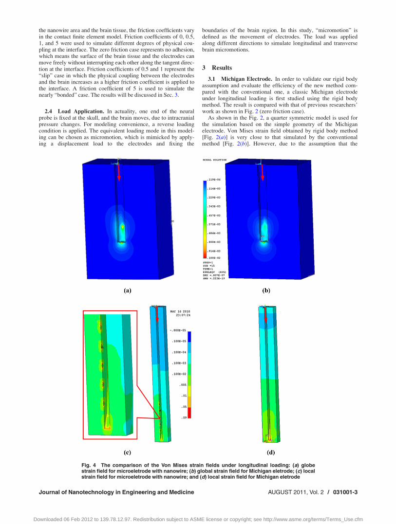
Fig. 4 The comparison of the Von Mises strain fields under longitudinal loading: (a) globestrain field for microeletrode with nanowire; (b) global strain field for Michigan eletrode; (c) localstrain field for microeletrode with nanowire; and (d) local strain field for Michigan eletrode
Journal of Nanotechnology in Engineering and Medicine AUGUST 2011, Vol. 2 / 031001-3
Downloaded 06 Feb 2012 to 139.78.12.97. Redistribution subject to ASME license or copyright; see http://www.asme.org/terms/Terms_Use.cfm
neural probe shank is rigid, no elastic element is generated in theprobe region, which significantly reduces the total number ofelements used in the simulation, hence saving computing time.One thing to be noted is that the new method also brings fasterconvergence in comparison with the conventional method, whichcreates a large material property mismatch at the interfacebetween the probe and the brain tissue by using elastic elementsfor both regions.
3.2 Microelectrode with Vertically Aligned Nanowires. Sincethe diameter of each nanowire is around 100 nm and the distancebetween two nanowires is less than 1 lm, the number of nano-wires is too huge to model them individually. Moreover, due tothe high Young’s modulus of the material used for the nanowire(Au), once the neural probe is implanted into the brain tissue,there are little deformations for both the nanowire and the tissueinside the nanowire area. Based on that, the nanowire areas aremodeled as five rigid cylinders at one side of the neural probe
shank. Each cylinder is 30 lm in diameter, 2 lm in height, andthe distance between the centers of two cylinders is 150 lm. Thedistance between the tip of the probe and the center of the nearestcylinder is 200 lm. Because the five rigid cylinders are at oneside of the neural probe, a half symmetry model is used instead ofquarter symmetry as shown in Fig. 3.
3.2.1 Effect of Longitudinal Loading. The comparison betweenVon Mises strain fields of the neural probe electrode with verti-cally aligned nanowires and the Michigan electrode under longitu-dinal loading (friction coefficient of 0.05 for both electrodes) isshown in Fig. 4. For the purpose of clear demonstration, theresults are divided into two parts—the global strain field of thebrain tissue, which is comparably far away from the electrode[Figs. 4(a) and 4(b)] and the local strain field of the brain tissuewhich is close to the electrode [Figs. 4(c) and 4(d)]. First, compar-ing the global strain fields, it can be found that unlike the symmet-ric strain field around the Michigan electrode the five verticallyaligned nanowire areas do increase the strain field along the
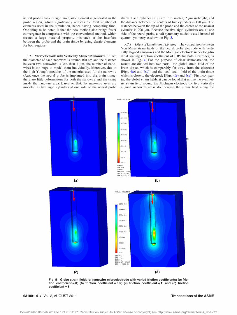
Fig. 5 Globe strain fields of nanowire microelectrode with varied friction coefficients: (a) fric-tion coefficient 5 0; (b) friction coefficient 5 0.5; (c) friction coefficient 5 1; and (d) frictioncoefficient 5 5
031001-4 / Vol. 2, AUGUST 2011 Transactions of the ASME
Downloaded 06 Feb 2012 to 139.78.12.97. Redistribution subject to ASME license or copyright; see http://www.asme.org/terms/Terms_Use.cfm
corresponding side of the probe electrode and generate an unsym-metric strain field as expected. Second, by comparing the localstrain fields, it can be found that the maximum strain is at the cir-cular interface between the nanowire area and the brain tissue forneural probe electrode with nanowires. However, for the Michi-gan electrode, the tip of the electrode has the maximum strain.
In order to study the effects of different physical coupling con-ditions at the interface between the neural probe shank and thebrain tissue, and also the interface between the nanowire area andthe brain tissue, global strain fields are plotted for a variety of fric-tion coefficients of 0, 0.5, 1, and 5, as shown in Fig. 5. Comparingthe results, it can be found that the Von Mises strain fieldincreases as the friction coefficient becomes larger.
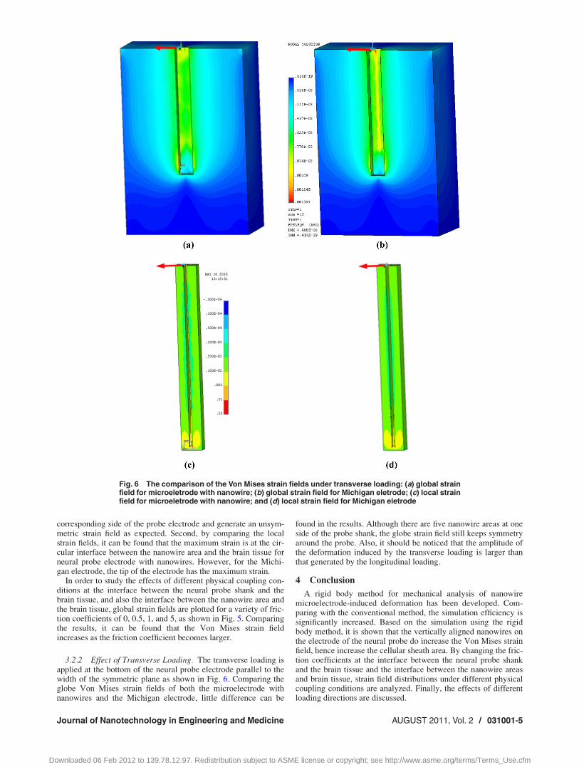
3.2.2 Effect of Transverse Loading. The transverse loading isapplied at the bottom of the neural probe electrode parallel to thewidth of the symmetric plane as shown in Fig. 6. Comparing theglobe Von Mises strain fields of both the microelectrode withnanowires and the Michigan electrode, little difference can be
found in the results. Although there are five nanowire areas at oneside of the probe shank, the globe strain field still keeps symmetryaround the probe. Also, it should be noticed that the amplitude ofthe deformation induced by the transverse loading is larger thanthat generated by the longitudinal loading.
4 Conclusion
A rigid body method for mechanical analysis of nanowiremicroelectrode-induced deformation has been developed. Com-paring with the conventional method, the simulation efficiency issignificantly increased. Based on the simulation using the rigidbody method, it is shown that the vertically aligned nanowires onthe electrode of the neural probe do increase the Von Mises strainfield, hence increase the cellular sheath area. By changing the fric-tion coefficients at the interface between the neural probe shankand the brain tissue and the interface between the nanowire areasand brain tissue, strain field distributions under different physicalcoupling conditions are analyzed. Finally, the effects of differentloading directions are discussed.
Fig. 6 The comparison of the Von Mises strain fields under transverse loading: (a) global strainfield for microeletrode with nanowire; (b) global strain field for Michigan eletrode; (c) local strainfield for microeletrode with nanowire; and (d) local strain field for Michigan eletrode
Journal of Nanotechnology in Engineering and Medicine AUGUST 2011, Vol. 2 / 031001-5
Downloaded 06 Feb 2012 to 139.78.12.97. Redistribution subject to ASME license or copyright; see http://www.asme.org/terms/Terms_Use.cfm
Acknowledgment
The authors thank Dr. Xiaoning Liu for very helpful discussionsin the finite element modeling part of this work. This researchwork was supported in part by the NSF-CREST Center (CNBMD),Grant No. HRD 1036494.
References[1] Guyton, D. L., and Hambrecht, F. T., 1974, “Theory and Design of Capacitor
Electrodes for Chronic Stimulation,” Med. Biol. Eng., 12, pp. 613–619.[2] Lebedev, M. A., and Nicolelis, M. A., 2006, “Brain-Machine Interfaces: Past,
Present and Future,” Trends Neurosci., 29, pp. 536–546.[3] Loudin, J. D., Simanovskii, D. M., Vijayraghavan, K., Sramek, C. K., Butterwick,
A. F., Huie, P., Mclean, G. Y., and Palanker, D. V., 2007, “Optoelectronic RetinalProsthesis: System Design and Performance” J. Neural Eng., 4, pp. S72–S84.
[4] Drake, K. L., Wise, K. D., Farraye, J., Anderson, D. J., and BeMent, S. L., 1988,“Performance of Planar Multisite Microprobes in Recording ExtracellularSingle-Unit Intracortical Activity,” IEEE Trans. Biomed. Eng., 35, pp. 719–732.
[5] Campbell, P. K., Jones, K. E., Huber, R. J., Horch, K. W., and Normann, R. A.,1991, “A Silicon-Based, Three-Dimensional Neural Interface: ManufacturingProcesses for an Intracortical Electrode Array,” IEEE Trans. Biomed. Eng., 38,pp. 758–768.
[6] Yoon, H., Hankins, P., Oh. S., Haubaugh, R. E., and Varadan, V. K., 2010,“Heterostructured IrO2/Au Nanowire Electrodes and Unit Recordings FromHippocampal Rat Brain,” J. Nanotech. Eng. Med., 1, pp. 021006.
[7] Yoon, H., Hankins, P., Varadan, V. K., and Haubaugh, R. E., 2008, “Dual Elec-trode Ensembles With Core and Shell Nanoelectrodes for Dopamine SensingApplications,” Electroanalysis, 20, pp. 1147–1150.
[8] Turner, J. N., Shain, W., Szarowski, D. H., Andersen, M., Martins, S., Isaacson,M., and Craighead, H., 1999, “Cerebral Astrocyte Response to MicromachinedSilicon Implants,” Exp. Neurol., 156, pp. 33–49.
[9] Fee, M. S., 2000, “Active Stabilization of Electrodes for Intracellular Recordingin Awake Behaving Animals,” Neuron, 27, pp. 461–468.
[10] Gilletti, A., and Muthuswamy, J., 2006, “Brain Micromotion Around Implantsin the Rodent Somatosensory Cortex,” J. Neural Eng., 3, pp. 189.
[11] Goldstein, S. R., and Salcman, M., 1973, “Mechanical Factors in the Design ofChronic Recording Intracortical Microelectrodes,” IEEE Trans. Biomed. Eng.,20, pp. 260.
[12] Reichert, W. M., 2008, Indwelling Neural Implants: Strategies for ContendingWith the In Vivo Environment, CRC, Boca Raton, FL.
[13] Lee, H., Bellamkonda, R. V., Sun, W., and Levenston, M. E., 2005,“Biomechanical Analysis of Silicon Microelectrode-Induced Strain in theBrain,” J. Neural Eng., 2, pp. 81–89.
[14] Subbaroyan, J., Martin, D. C., and Kipke, D. R., 2005, “A Finite-ElementModel of the Mechanical Effects of Implantable Microelectrodes in the Cere-bral Cortex,” J. Neural Eng., 2, pp. 103–113.
[15] Skringar, O., Nabavi, A., and Duncan, J., 2002, “Model-Driven Brain ShiftCompensation,” Med. Image Anal., 6, pp. 361–373.
[16] Kyriacou, S. K., Mohamed, A., Miller, K., and Neff, S., 2002, “Brain Mechan-ics for Neurosurgery: Modeling Issues,” Biomech. Model Mechanobiol., 1, pp.151–164.
[17] Gilchrist, M. D., and O’Donoghue, D., 2000, “Simulation of the Developmentof Frontal Head Impact Injury,” Comput. Mech., 26, pp. 229–235.
[18] Ommaya, A. K., 1968, “Mechanical Properties of Tissues of the Nervous Sys-tem,” J. Biomech., 1, pp. 127–138.
[19] Gefen, A., and Margulies, S. S., 2004, “Are In Vivo and In Situ Brain TissuesMechanically Similar?,” J. Biomech., 37, pp. 1339–1352.
[20] Yoon, H., Deshpande, D. C., Varadan, V. K., Kim, T., Jeong, E., and Harbaugh,R. E., 2010, “Development of Titanium Needle Probes for Neural Recording,”J. Nanotech. Eng. Med., 1, pp. 011004.
[21] Yoon, H., Deshpande, D. C., Ramachandran, V., and Varadan, V. K., 2007,“Aligned Nanowire Growth Using Lithography-Assisted Bonding of Poly-carbonate Template for Neural Probe Electrodes,” Nanotechnology, 19,pp. 025304.
031001-6 / Vol. 2, AUGUST 2011 Transactions of the ASME
Downloaded 06 Feb 2012 to 139.78.12.97. Redistribution subject to ASME license or copyright; see http://www.asme.org/terms/Terms_Use.cfm


![Group 56 Zhimeng, Han 019958 Hui, Liu 020533 Rui, Zhao 025142 Jinyi, Zhou 024561 Siying Zhu 018275 References Apple, 2012. [Online]. Available at: [Accessed](https://img.pdfslide.net/doc/110x75/551bba00550346b4588b45fe/group-56-zhimeng-han-019958-hui-liu-020533-rui-zhao-025142-jinyi-zhou-024561-siying-zhu-018275-references-apple-2012-online-available-at-accessed.jpg)